WO2013168347A1 - Information processing apparatus, method for controlling the information processing apparatus, and storage medium - Google Patents
Information processing apparatus, method for controlling the information processing apparatus, and storage medium Download PDFInfo
- Publication number
- WO2013168347A1 WO2013168347A1 PCT/JP2013/002169 JP2013002169W WO2013168347A1 WO 2013168347 A1 WO2013168347 A1 WO 2013168347A1 JP 2013002169 W JP2013002169 W JP 2013002169W WO 2013168347 A1 WO2013168347 A1 WO 2013168347A1
- Authority
- WO
- WIPO (PCT)
- Prior art keywords
- display
- display range
- instruction
- processing apparatus
- moving
- Prior art date
Links
Images


Classifications
-
- G—PHYSICS
- G06—COMPUTING; CALCULATING OR COUNTING
- G06F—ELECTRIC DIGITAL DATA PROCESSING
- G06F3/00—Input arrangements for transferring data to be processed into a form capable of being handled by the computer; Output arrangements for transferring data from processing unit to output unit, e.g. interface arrangements
- G06F3/01—Input arrangements or combined input and output arrangements for interaction between user and computer
- G06F3/048—Interaction techniques based on graphical user interfaces [GUI]
- G06F3/0484—Interaction techniques based on graphical user interfaces [GUI] for the control of specific functions or operations, e.g. selecting or manipulating an object, an image or a displayed text element, setting a parameter value or selecting a range
- G06F3/0485—Scrolling or panning
-
- G—PHYSICS
- G06—COMPUTING; CALCULATING OR COUNTING
- G06F—ELECTRIC DIGITAL DATA PROCESSING
- G06F16/00—Information retrieval; Database structures therefor; File system structures therefor
-
- G—PHYSICS
- G06—COMPUTING; CALCULATING OR COUNTING
- G06F—ELECTRIC DIGITAL DATA PROCESSING
- G06F16/00—Information retrieval; Database structures therefor; File system structures therefor
- G06F16/90—Details of database functions independent of the retrieved data types
- G06F16/95—Retrieval from the web
- G06F16/953—Querying, e.g. by the use of web search engines
- G06F16/9537—Spatial or temporal dependent retrieval, e.g. spatiotemporal queries
-
- G—PHYSICS
- G06—COMPUTING; CALCULATING OR COUNTING
- G06F—ELECTRIC DIGITAL DATA PROCESSING
- G06F3/00—Input arrangements for transferring data to be processed into a form capable of being handled by the computer; Output arrangements for transferring data from processing unit to output unit, e.g. interface arrangements
- G06F3/01—Input arrangements or combined input and output arrangements for interaction between user and computer
- G06F3/048—Interaction techniques based on graphical user interfaces [GUI]
- G06F3/0481—Interaction techniques based on graphical user interfaces [GUI] based on specific properties of the displayed interaction object or a metaphor-based environment, e.g. interaction with desktop elements like windows or icons, or assisted by a cursor's changing behaviour or appearance
-
- G—PHYSICS
- G06—COMPUTING; CALCULATING OR COUNTING
- G06F—ELECTRIC DIGITAL DATA PROCESSING
- G06F3/00—Input arrangements for transferring data to be processed into a form capable of being handled by the computer; Output arrangements for transferring data from processing unit to output unit, e.g. interface arrangements
- G06F3/01—Input arrangements or combined input and output arrangements for interaction between user and computer
- G06F3/048—Interaction techniques based on graphical user interfaces [GUI]
- G06F3/0484—Interaction techniques based on graphical user interfaces [GUI] for the control of specific functions or operations, e.g. selecting or manipulating an object, an image or a displayed text element, setting a parameter value or selecting a range
- G06F3/04845—Interaction techniques based on graphical user interfaces [GUI] for the control of specific functions or operations, e.g. selecting or manipulating an object, an image or a displayed text element, setting a parameter value or selecting a range for image manipulation, e.g. dragging, rotation, expansion or change of colour
-
- G—PHYSICS
- G06—COMPUTING; CALCULATING OR COUNTING
- G06T—IMAGE DATA PROCESSING OR GENERATION, IN GENERAL
- G06T11/00—2D [Two Dimensional] image generation
-
- G—PHYSICS
- G06—COMPUTING; CALCULATING OR COUNTING
- G06T—IMAGE DATA PROCESSING OR GENERATION, IN GENERAL
- G06T11/00—2D [Two Dimensional] image generation
- G06T11/60—Editing figures and text; Combining figures or text
-
- G—PHYSICS
- G06—COMPUTING; CALCULATING OR COUNTING
- G06T—IMAGE DATA PROCESSING OR GENERATION, IN GENERAL
- G06T3/00—Geometric image transformation in the plane of the image
- G06T3/20—Linear translation of a whole image or part thereof, e.g. panning
-
- G—PHYSICS
- G09—EDUCATION; CRYPTOGRAPHY; DISPLAY; ADVERTISING; SEALS
- G09B—EDUCATIONAL OR DEMONSTRATION APPLIANCES; APPLIANCES FOR TEACHING, OR COMMUNICATING WITH, THE BLIND, DEAF OR MUTE; MODELS; PLANETARIA; GLOBES; MAPS; DIAGRAMS
- G09B29/00—Maps; Plans; Charts; Diagrams, e.g. route diagram
- G09B29/10—Map spot or coordinate position indicators; Map reading aids
- G09B29/106—Map spot or coordinate position indicators; Map reading aids using electronic means
Definitions
- the present invention relates to an information processing apparatus for controlling map display.
- the present invention is directed to reducing the process of user operations for searching for a target image.
- an information processing apparatus capable of displaying in a display area a partial range of a map image as a display range includes an object display means for displaying an object associated with location information at a location corresponding to the location information on the map image in the display area, an operation means for receiving an instruction corresponding to a user operation, and a display control means for moving, if an instruction for moving the display range of the map image is received by the operation means, the map image to an instructed direction to display thereof, wherein the instruction for moving the display range of the map image includes directional information, and wherein if the instruction for moving the display range of the map image received by the operation means satisfies a first condition, the display control means performs control to move the display range until an object not displayed in the display area during receiving the instruction is displayed, and then stop moving the display range.
- Fig. 1 is a block diagram illustrating a configuration of an information processing apparatus according to a first exemplary embodiment.
- Fig. 2 schematically illustrates a management table according to the first exemplary embodiment.
- Fig. 3A illustrates example of display screens according to the first exemplary embodiment.
- Fig. 3B illustrates example of display screens according to the first exemplary embodiment.
- Fig. 3C illustrates example of display screens according to the first exemplary embodiment.
- Fig. 4 illustrates a positional relationship of a display range according to the first exemplary embodiment.
- FIG. 5 is a flowchart illustrating an operation of the information processing apparatus according to the first exemplary embodiment.
- Fig. 6 illustrates a search range according to the first exemplary embodiment.
- Fig. 7 schematically illustrates a management table according to a second exemplary embodiment.
- Fig. 8 illustrates a positional relationship of a display range according to the second exemplary embodiment.
- Fig. 9 is a flowchart illustrating an operation of an information processing apparatus according to the second exemplary embodiment.
- Fig. 10 illustrates an example of a display screen according to the second exemplary embodiment.
- Fig. 11 illustrates an example of a screen for setting a search condition according to the second exemplary embodiment.
- Fig. 12A which composes Fig.
- FIG. 12 is a flowchart illustrating an operation of an information processing apparatus according to a third exemplary embodiment.
- Fig. 12B which composes Fig. 12, is a flowchart illustrating an operation of an information processing apparatus according to a third exemplary embodiment.
- Fig. 13 illustrates an example of a screen for setting a condition according to the third exemplary embodiment.
- Fig. 14 illustrates an example of a screen for setting a start condition according to the third exemplary embodiment.
- Fig. 1 illustrates a configuration of an information processing apparatus according to the present exemplary embodiment.
- the information processing apparatus according to the present exemplary embodiment is, for example, a personal computer, a mobile phone, a digital camera, and a tablet device.
- a control unit 101 controls each unit of an information processing apparatus 100 based on an input signal and a program (described below). Instead of being controlled by the control unit 101, the entire information processing apparatus may be controlled by a plurality of hardware components sharing processings.
- a memory 103 is used as a buffer memory for temporarily storing data, an image display memory for a display unit 106, and a work area for the control unit 101.
- An operation unit 105 receives an instruction to the information processing apparatus 100 from the user.
- the operation unit 105 includes a keyboard and a pointing device, such as a mouse, a touchpad, and a touch panel.
- a touch panel capable of detecting contact to the display unit 106 is included in the operation unit 105.
- the control unit 101 detects at intervals of unit time the coordinates of a contact point on the touch panel at which a finger or pen touches. Thus, the following operations made on the touch panel can be detected.
- touch-down An action to touch the touch panel with the finger or pen (hereinafter referred to as "touch-down”). A state where the finger or pen is in contact with the touch panel (hereinafter referred to as “touch-on”). An action to move the finger or pen held in contact with the touch panel (hereinafter referred to as “move”). An action to detach the finger or pen from the touch panel (hereinafter referred to as “touch-up”). A state where the finger or pen is not in contact with the touch panel (hereinafter referred to as "touch-off”).
- the moving direction of the finger or pen moving on the touch panel can be determined for each of the vertical and horizontal components on the touch panel based on change in the coordinates of the contact point. If the control unit 101 detects a move operation equal to or longer than a predetermined distance from the coordinates of the touch-down position, the control unit 101 determines that a drag operation has been performed. If the control unit 101 detects a move operation at a speed equal to or faster than a predetermined speed from the touch-down position and subsequently detects a touch-up operation, the control unit 101 determines that a flick operation has been made.
- a flick is an operation in which the user quickly moves the finger held in contact with the touch panel equal to or longer than a predetermined distance and subsequently detach the finger therefrom, in other words, the user quickly trace in such a way as to flip the surface of the touch panel with the finger.
- the predetermined distance is set to such a value that the movement of the coordinates of the contact point can be almost ignored. This value is used to prevent the movement of the coordinates due to an unintended finger wobble from being detected as a flick or drag operation. Therefore, for example, the predetermined distance is preliminarily set to a value larger than the moving distance of the coordinates due to an unintended finger wobble.
- a touch-down operation at a plurality of positions (generally referred to as multi-touch) can be detected. The above-described operations can be detected for the coordinates of each point of a multi-touch operation.
- the display unit 106 displays data stored in the information processing apparatus 100 and data supplied thereto.
- the display unit 106 displays a display area drawn in a window of an information management application program (described below).
- the information processing apparatus 100 may not necessarily include the display unit 106 as long as the information processing apparatus 100 can be connected with the display unit 106 and is provided with at least a display control function for controlling display of the display unit 106.
- a storage medium 110 stores various control programs executed by the control unit 101, an operating system (OS), contents information (image and audio files), the information management application program, and map images.
- OS operating system
- contents information image and audio files
- map images an image is prepared for each fixed scale interval.
- An image with a smaller scale stores more detailed information.
- image files are handled as an Exchangeable Image File Format-Joint Photographic Experts Group (EXIF-JPEG) image file.
- EXIF-JPEG Exchangeable Image File Format-Joint Photographic Experts Group
- the storage medium 110 may be a different component from the information processing apparatus 100 or included in the information processing apparatus 100. In other words, it is only necessary that the information processing apparatus 100 has a means for accessing the recording medium 110.
- a network interface 111 is used to connect to a network circuit, such as the Internet.
- a network circuit such as the Internet.
- image files and map images are stored in the storage medium 110, the present invention is similarly applicable to a case where image files and map images are obtained from an external device via the network interface 111.
- the network interface 111 accesses an external device via communication conforming to the Hypertext Transfer Protocol (HTTP).
- HTTP Hypertext Transfer Protocol
- the information processing apparatus 100 may be achieved by a single information processing apparatus or an as-needed plurality of information processing apparatuses having distributed each function. If the information processing apparatus 100 is configured with a plurality of information processing apparatuses, these apparatuses are connected, for example, via a local area network (LAN) to enable communication therebetween.
- the information processing apparatus 100 may further include an imaging unit (including a lens, a shutter, etc.) for forming a subject's image and generating image data. Specifically, image files may be data captured by the information processing apparatus 100.
- the following operation of the information management application is implemented when the control unit 101 reads the information management application and OS from the storage medium 110 and performs control according to the information management application.
- the information management application according to the present exemplary embodiment is provided with a map display mode in which the imaging location of an image file stored in the storage medium 110 is superimposed on the map image.
- location information and date information are stored in the header area of an image file.
- the location information indicates the imaging location and the date information indicates the imaging date.
- the control unit 101 suitably performs display by referring to these pieces of information.
- the information management application manages only image files specified to be managed by the information management application according to a user instruction out of image files recorded on the recording medium 110.
- a user instruction out of image files recorded on the recording medium 110.
- the user can select image files to be managed by the information management application out of image files stored in the recording medium 110.
- the image files determined to be managed by the information management application according to a user instruction are registered to a management table stored in the information management application.
- Fig. 2 schematically illustrates the management table for managing various data for each of image files stored in the recording medium 110.
- an image identifier (ID) 201 is used to identify each image file.
- the information management application distinguishes and manages each image file based on the image ID 201.
- An image name 202 indicates the name of each image file.
- An image path 203 indicates which area on the storage medium 110 the image file is stored in.
- the information management application refers to the image path 203 to access the image file.
- An imaging location 204 is location information indicating the imaging location of each image file. In the present exemplary embodiment, location information is recorded as the latitude and longitude. Based on the latitude and longitude, the information management application can display on the map a pin indicating the imaging location of an image file.
- the information management application can display on the map a pin indicating the imaging location of an image file by referring to the management table.
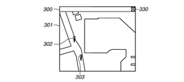
- Fig. 3A illustrates an example of a map display screen displayed referring to the management table illustrated in Fig. 2.
- the map image is displayed in the display area 301 of a window 300.
- a pin 302 indicating the imaging location of an image file 1 and a pin 303 indicating the imaging location of an image file 2 are displayed superimposed with the map image. Pins corresponding to image files 3 and 4 are not displayed since the imaging locations thereof are not included in the display range.
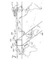
- Fig. 4 illustrates a relationship between the display range on the map image displayed in the display area 301 illustrated in Fig. 3A and the imaging locations of the image files 3 and 4.
- Fig. 4 illustrates a portion clipped from the map for description.
- the display range on the map image displayed in the display area 301 illustrated in Fig. 3A corresponds to a range 411 illustrated in Fig. 4.
- pins 304 and 305 indicate the imaging locations of the image files 3 and 4, respectively. If the screen as illustrated in Fig. 3A is displayed, the user can display a map image corresponding to any desired display range.
- the user can scroll the map image in the direction of the drag operation (hereinafter referred to as drag direction).
- drag direction the direction of the drag operation
- the display range can be moved in a direction opposite to the drag direction.
- the user can input an instruction for moving the display range in the lower-right direction (in a direction opposite to the direction 413 illustrated in Fig. 4). If the user inputs this instruction, the map image and the pins scroll in the drag direction in response to the drag operation. In other words, the display range is moved in the lower-right direction (in a direction opposite to the direction 413 illustrated in Fig. 4) from the range 411.
- a screen as illustrated in Fig. 3B is displayed.
- the display range on the map image displayed in the display area 301 illustrated in Fig. 3B corresponds to the range 412 illustrated in Fig. 4.
- the display range illustrated in Fig. 3B does not include the imaging locations of the image files 1 to 4 in the management table. Therefore, no pin is displayed on the map image in the display area 301 illustrated in Fig. 3B.
- a drag operation is an operation made on the screen, only a limited range can be newly displayed with one drag operation.
- a distance that the display range can be moved with one drag operation assumed to be from the range 411 to the range 412 illustrated in Fig. 4.
- the control unit 101 if a predetermined condition is satisfied upon acceptance of a drag operation, the control unit 101 automatically keeps scrolling the map in a direction corresponding to the drag direction until a pin appears. In other words, by continuously passing through a range where a pin does not displayed without stopping at thereof, following the contact point, the control unit 101 automatically keeps moving the display range up to a range where a pin is displayed.
- the predetermined condition is, for example, a flick operation.
- This predetermined condition is an example of a first condition.
- the user can input an instruction for performing automatic scrolling, for example, by performing a flick operation. This eliminates the need of repetitively performing the operation for moving the display range, for example, from the range 411 to the range 414.
- auto-scroll is referred to as auto-scroll.
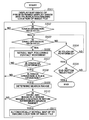
- Fig. 5 is a flowchart illustrating an operation of the information processing apparatus 100 for displaying the map .
- the processing illustrated in this flowchart is started, for example, if the user selects a menu and an instruction for displaying the map display screen is received, and then implemented by the control unit 101 controlling each unit of the information processing apparatus 100 according to the OS and the information management application. This also applies to the subsequent flowcharts.
- step S501 the control unit 101 reads a map image of a predetermined scale from the storage medium 110, and displays thereof in the display area of the information management application window. At the same time, the control unit 101 further reads an image file, and arranges to display in the display area a pin indicating the imaging location of the image file based on the location information thereof. As a result of the processing in step S501, for example, a screen as illustrated in Fig. 3A is displayed.
- step S502 the control unit 101 determines whether an instruction for a user operation received via the operation unit 105 is received.
- the user can input an instruction for moving the display range via the operation unit 105.
- a description is made for an example in which the user inputs an instruction by using the touch panel of the operation unit 105.
- the control unit 101 determines whether a user touch operation is received via the touch panel of the operation unit 105. For example, the user can input an instruction for moving the display range of the map by performing a drag operation. Further, the user can select an END button 330 by performing a touch-up operation in the display area of the END button 330. Thus, the user can input an instruction for ending of processing of this flowchart.
- step S502 If the control unit 101 determines that a touch operation is not received (NO in step S502), the control unit 101 repeats the processing in step S502. Otherwise, if the control unit 101 determines that a touch operation is received (YES in step S502), the processing proceeds to step S503.
- step S503 the control unit 101 determines whether the received touch operation is a drag operation. Specifically, the control unit 101 stores in the memory 103 the starting position of the touch operation (i.e., touch-down position). Then, the control unit 101 compares the starting position of the touch operation (i.e., touch-down position) with the latest contact point position detected at intervals of unit time to determine whether the distance between contact points is equal to or larger than the predetermined distance. Specifically, the control unit 101 determines whether the finger has moved equal to or longer than the predetermined distance from the starting position of the touch operation to determine whether the received touch operation is a drag operation.
- the control unit 101 determines whether the received touch operation is a drag operation.
- step S504 the control unit 101 determines whether a touch operation is performed, specifically, it detects whether a touch-up operation is performed. If the control unit 101 determines that a touch-up operation is not performed (NO in step S504), the processing returns to step S503.
- step S504 This flow of processing applies to a case, for example, where the finger remains at the touch-down position without moving the contact point. Otherwise, if the control unit 101 determines that a touch-up operation is performed (YES in step S504), the processing proceeds to step S505. This flow of processing applies to a case, for example, where the user performs a touch-up operation at the touch-down position without moving the contact point.
- step S505 the control unit 101 determines whether the END button is selected, specifically, the control unit 101 determines whether the END button is selected by determining whether the position touched up is the position of the END button.
- the processing ends the processing of this flowchart. Otherwise, if the control unit 101 determines that the END button is not selected (NO in step S505), the processing returns to step S502.
- step S503 Processing performed if the control unit 101 determines that the received touch operation is not a drag operation in step S503 has specifically been described above.
- step S503 the control unit 101 determines that the received touch operation is a drag operation. In this case, the processing proceeds to step S506.
- step S506 the control unit 101 reads a map image corresponding to the contact point of the drag operation from the storage medium 110 and then displays thereof. At the same time, if the imaging location of an image file is included in the display range corresponding to the contact point of the drag operation, the control unit 101 arranges at the relevant position a pin indicating the imaging location of the image file. Thus, the control unit 101 performs control to update the map image to scroll the map, following the movement of the contact point.
- the control unit 101 repeats the processing in step S506 until the control unit 101 determines in step S507 that a touch-up operation is detected, i.e., the drag operation is completed. Specifically, once the drag operation is received, the control unit 101 scrolls the map each time the movement of the contact point is detected, following the contact point, and repeats this processing until the user performs a touch-up operation.
- step S507 the control unit 101 determines whether the drag operation is completed, specifically, determination is made by detecting whether a touch-up operation is performed. If the control unit 101 determines that the drag operation is not completed (NO in step S507), the control unit 101 repeats the processing in steps S506 and S507. Otherwise, if the control unit 101 determines that the drag operation is completed (YES in step S507), the processing proceeds to step S508.
- step S508 the control unit 101 determines whether the received drag operation satisfies a predetermined condition.
- the predetermined condition is a "flick operation". In this case, if a touch-up operation is detected after the drag operation, the control unit 101 acquires the magnitude of a moving vector of the coordinate of the contact point per unit time immediately before the touch-up operation.
- the control unit 101 store in the memory 103 a plurality of recently detected coordinates out of the coordinates of contact points on the touch panel detected at intervals of unit time.
- the moving vector is calculated based on the plurality of the coordinates.
- the control unit 101 obtains the moving vector based on the coordinates of the latest two points after the timing of the touch-up operation.
- the magnitude of the moving vector indicates the moving speed of the contact point immediately before the touch-up operation.
- the control unit 101 determines whether the magnitude of the moving vector is equal to or larger than a predetermined value to determine whether the move operation is performed at speed equal to or faster than predetermined speed.
- the control unit 101 determines that a flick operation is performed.
- a flick operation is used as the predetermined condition.
- Quickly performing a move operation and a touch-up operation i.e., performing a flick operation
- a touch-up operation i.e., performing a flick operation
- the control unit 101 uses the flick operation as the predetermined condition.
- step S508 If the control unit 101 determines that the received touch operation is not a flick operation (NO in step S508), the processing returns to step S502, leaving the display range upon completion of the drag operation displayed.
- step S508 determines that the received touch operation is a flick operation (YES in step S508), the control unit 101 determines that an instruction for performing auto-scroll is received, and the processing proceeds to step S509.
- step S509 the control unit 101 determines as a search range a range extending in a direction opposite to the direction of the received flick operation and having the width of the display range.
- the direction of the flick operation (hereinafter referred to flick direction) is obtained by detecting the direction of the moving vector of the contact point immediately before the touch-up operation.
- step S510 the control unit 101 determines whether there exists an imaging location of an image file is included in the search range.
- the search range is determined to be a range (range 420) extending in the downward direction and having the width of the display area corresponding to the relevant direction. Then, the control unit 101 determines whether there exists an image file whose imaging location is included in the search range. In this case, the control unit 101 determines the existence of an image file by referring to imaging locations of image files managed by the management table.
- step S510 the control unit 101 determines that there is no image file whose imaging location is included in the search range.
- the search range is determined to be a range (range 430) extending in a direction opposite to the direction 413 and having the width of the display range corresponding to the relevant direction.
- the control unit 101 determines whether there exists an image file whose imaging location is included in the search range.
- the imaging locations of the image files 3 and 4 are included in the range 430. Therefore, in this case, the control unit 101 determines that there exists an image file whose imaging location is included in the search range.
- search range is illustrated in Fig. 4 for description, the search range is actually determined over the entire range of the map stored in the storage medium 110. Further, if the map data is configured to loop in the east-west direction, as with the global map illustrated in Fig. 6, the search range may be determined on a loop basis.
- the search range is extended to a range 620 which includes not only the east side of the range 601 but also the west side (loop-back side) thereof.
- a range 630 is determined to be the search range and a range on the opposite side is not the search range.
- the search range determined by the processing in step S509 is based on the flick direction, the coordinates (latitude and longitude) of the four corners of the display range upon reception of a flick operation, and the coordinates of the entire map.
- the width of the search range is determined based on two diagonal points corresponding to the flick direction, out of the coordinates of the four corners of the display range rectangle upon reception of a flick operation. In this case, the two diagonal points are selected so as to obtain a wider search range.
- step S510 If the control unit 101 determines that there is no image file whose imaging location is included in the search range (NO in step S510), the processing returns to step S502. Specifically, if there is no image in the direction corresponding to the flick direction, auto-scroll is not performed even if a flick operation is performed.
- control unit 101 may notify the user of the fact that there is no file in a direction corresponding to the flick operation. For example, the notification may be made by displaying an error icon or displaying such a message as "NO FILE EXISTS IN THE SPECIFIED DIRECTION" for a predetermined period of time.
- step S510 if the control unit 101 determines that there exists an image file whose imaging location is included in the search range (YES in step S510), the processing proceeds to step S511.
- step S511 the control unit 101 performs auto-scroll. Specifically, the control unit 101 automatically moves the display area while sequentially reading and displaying map images along the flick direction. In the auto-scroll operation, the control unit 101 keeps moving the display range until a pin indicating the imaging location closest to the display range upon reception of the instruction, out of the imaging locations in the search range, is displayed in the display area.
- the scrolling speed for auto-scroll is changed according to the magnitude of the moving vector of the contact point per unit time immediately before the touch-up operation. Specifically, performing a flick operation faster moves the display range at higher scrolling speed. As described in the description of the operation unit 105 illustrated in Fig. 1, a flick operation is detected if the user draws a stroke more quickly than the drag operation.
- the magnitude of the moving vector of the contact point per unit time immediately before a touch-up in a flick operation is larger than at least the magnitude of the moving vector of the contact point per unit time in a drag operation. Therefore, if the display range moves in a same distance, the display range moves faster in a flick operation than in a drag operation.
- auto-scroll enables automatically scrolling the map with only one operation without repeatedly performing the operation, reducing time of repeating an operation. This means that using auto-scroll enables displaying a range equivalent to the range 414 faster than repeating a drag operation. Then, the processing returns to step S502.
- the information processing apparatus 100 when the information management application displays the map image has specifically been described above. As described above, if the imaging location of an image file exists in the direction corresponding to a user operation, the information processing apparatus 100 according to the present exemplary embodiment performs map image auto-scroll until the imaging location of the image file is included in the display range.
- the user only needs to perform a flick operation only once, and does not need to repetitively performing an operation for scrolling the map image until the imaging location of the image file is included in the display range. Since auto-scroll stops if an imaging location of an image file is included in the display range, the user does not need to check whether a pin indicating the shooting location of an image file is displayed in a range newly displayed in response to a scroll instruction. This reduces the process of user operations for searching for a target image, shortening the time until the target image is displayed.
- a second exemplary embodiment will be described below.
- auto-scroll is stopped if a pin indicating the imaging location of the image is displayed in the display range. Specifically, all of image files are subjected to search with auto-scroll.
- a condition used by the control unit 101 to determine whether an image is subjected to search will be referred to as a search condition.
- the search condition is an example of a second condition.
- Fig. 7 schematically illustrates a management table according to the present exemplary embodiment.
- An image management application manages attribute information for each image file. For example, as illustrated in Fig. 7, the image management application manages a rating value, imaging date, shooting location, etc. for each image file by using the management table.
- this management table is to be considered as an example, and the management table may include other pieces of information in addition to the ones illustrated in Fig. 7. Further, the attribute information of image files is not limited to the rating value, imaging date, and imaging location.
- the attribute information records other various information, such as information indicating the model of an imaging apparatus used for imaging, the weather at the time of imaging, the white balance at the time of imaging, and the diaphragm value at the time of imaging.
- Image files 1 to 6 are stored in the management table illustrated in Fig. 7. Of these, the image files 1 to 4 are the same as those in the first exemplary embodiment. The image files 5 and 6 are newly appended to the management table.
- Fig. 8 Relationships between the imaging locations of the image files 1 to 6 are illustrated in Fig. 8.
- elements having the same function as those in Fig. 4 are assigned the same reference numeral.
- the imaging locations of the image files 1 to 4 are indicated by pins 302, 303, 304, and 305, respectively.
- the imaging location of the image file 5 is indicated by a pin 801.
- the imaging location of the image file 6 is indicated by a pin 802.
- a flick operation is received if a range equivalent to the range 411 illustrated in Fig. 8 is displayed as the display range, and the range 430 is determined as the search range.
- the imaging locations of the image files 3 to 5 are included in this search range.
- the control unit 101 performs similar processing to the case where a drag operation is received. This is because the image file 6 corresponding to the pin 802 has rating 0, and the condition "IMAGE WITH RATING EQUAL TO OR HIGHER THAN 3" is not satisfied.
- Fig. 9 is a flowchart illustrating an operation performed by the information processing apparatus 100 to achieve the above-described operation.
- the flowcharts in Figs. 5 and 9 have many duplicated steps, descriptions will be made centering on elements specific to the present exemplary embodiment, and redundant description thereof will be omitted.
- step S901 the control unit 101 performs similar processing to step S501.
- the control unit 101 displays a screen 1000 as illustrated in Fig. 10.
- Fig. 10 elements having the same function as those in Fig. 3A are assigned the same reference numeral.
- step S902 the control unit 101 determines whether an operation is received from the user via the operation unit 105.
- the user can input an instruction for moving the display range via the operation unit 105.
- the user can input an instruction for moving the display range of the map by performing a drag operation. Further, the user can select a SET button 1001 by performing a touch-up operation in the display area of the SET button 1001.
- the SET button 1001 is used to set a condition of images at which scrolling is stopped at the time of auto-scroll. In other words, this button is used to set a condition of images subjected to search.
- the user can input an instruction for displaying a setting menu for setting the condition of images subjected to search by selecting the SET button 1001. Further, the user can select the END button 330 by performing a touch-up operation in the display area of the END button 330. Thus, the user can input an instruction for ending the process of this flowchart.
- step S902 If the control unit 101 determines that a touch operation is not received (NO in step S902), the processing returns to step S902. Otherwise, if the control unit 101 determines that a touch operation is received (YES in step S902), the processing proceeds to step S903.
- step S903 similar to step S503 illustrated in Fig. 5, the control unit 101 determines whether the received touch operation is a drag operation.
- step S911 the control unit 101 determines that the received touch operation is not a drag operation. In this case, the processing proceeds to step S911.
- step S911 similar to step S504 illustrated in Fig. 5, the control unit 101 determines whether a touch operation is performed, specifically, it determines whether a touch operation is performed by detecting whether a touch-up operation is performed. If the control unit 101 determines that a touch-up operation is not performed (NO in step S911), the processing returns to step S903. Otherwise, if the control unit 101 determines that a touch-up operation is performed (YES in step S911), the processing proceeds to step S912.
- step S912 the control unit 101 determines whether the END button is selected, specifically, it determines whether the END button is selected by determining whether the touch-up position is the position of the END button. If the control unit 101 determines that the END button is selected (YES in step S912), the processing ends the process of this flowchart. Otherwise, if the control unit 101 determines that the END button is not selected (NO in step S912), the processing proceeds to step S913.
- step S913 the control unit 101 determines whether the SET button is selected, specifically, it determines whether the SET button is selected by determining whether the touch-up position is the position of the SET button. If the control unit 101 determines that the SET button is not selected (NO in step S913), the processing returns to step S901. Otherwise, if the control unit 101 determines that the SET button is selected (YES in step S913), the processing proceeds to step S914.
- step S914 the control unit 101 displays a screen 1100 illustrated in Fig. 11 and receives a user instruction.
- Fig. 11 illustrates an example of a screen for setting a condition of images subjected to search.
- the user can set the relevant condition as a search condition.
- the settable search condition is not limited to the rating of image files.
- selecting the condition "IMAGE CAPTURED IN LAST ONE MONTH" in the selection frame 1101 illustrated in Fig. 11 enables setting a condition used in searching for image files captured in the last one month. Further, performing a drag or flick operation in the vertical direction within the selection frame 1101 enables scrolling condition items therein to make hidden condition items visible. Further, by touching down on the display area of the CANCEL button 1102, the user can select the CANCEL button 1102. Thus, the user can end display of the setting menu and input an instruction for returning to the screen 1000 illustrated in Fig. 10.
- step S915 the control unit 101 determines whether the CANCEL button 1102 is selected. If the control unit 101 determines that the CANCEL button 1102 is selected (YES in step S915), the processing returns to step S901. Otherwise, if the control unit 101 determines that the CANCEL button 1102 is not selected (NO in step S915), the processing proceeds to step S916.
- step S916 the control unit 101 determines whether a condition is selected. If the control unit 101 determines that a condition is not selected (NO in step S916), the processing returns to step S915. Otherwise, if the control unit 101 determines that a condition is selected (YES in step S916), the processing proceeds to step S917.
- step S917 the control unit 101 retains the selected condition in the nonvolatile memory 104 as a search condition. Then, the processing returns to step S901.
- step S903 Processing for receiving a setting instruction if the control unit 101 determines in step S903 that the received touch operation is not a drag operation has specifically been described above.
- step S903 the control unit 101 determines that the received touch operation is a drag operation (YES in step S903).
- the processing proceeds to step S904.
- steps S904 to S908 is similar to processing in steps S506 to S510 illustrated in Fig. 5, and redundant description thereof will be omitted. Similar to step S508, if the processing returns from step S906 to step S902, the display range upon completion of the last drag operation remains displayed.
- step S909 the control unit 101 determines whether there exists an image file satisfying the search condition out of image files whose imaging locations are determined to be included in the display range in step S908.
- the search condition used in this case is the search condition stored in the nonvolatile memory 104 in step S917.
- control unit 101 searches for image files with rating equal to or higher than 3 out of image files whose imaging locations are determined to be included in the display range in step S908.
- control unit 101 refers to the rating stored in the management table.
- the image file 4 has rating equal to or higher than 3.
- the search range determined in step S907 is the range 420 illustrated in Fig. 8
- the imaging location of the image file 6 is included in the search range.
- the image file 6 has rating 0 and therefore does not satisfy the condition "IMAGE WITH RATING EQUAL TO OR HIGHER THAN 3". Therefore, in this case, the control unit 101 determines that there is no image file satisfying the search condition, and processing returns to step S902.
- step S909 the control unit 101 determines that there exists an image file satisfying the search condition, and the processing proceeds to step S910.
- step S910 the control unit 101 scrolls the display range until the shooting location of an image file closest to the current display range, out of image files satisfying the search condition, is included in the display range.
- the control unit 101 does not stop scrolling in the display range displaying the pin indicating the imaging location of the image file 5 but scrolls the map up to the display range equivalent to the range 414, and then stops scrolling.
- the processing returns to step S902.
- step S903 Processing for receiving an instruction for changing the display range if the control unit 101 determines in step S903 that the received touch operation is a drag operation has specifically been described above.
- the present exemplary embodiment is described to enable setting a condition used in searching for images by auto-scroll. Thus, it is possible to quickly display an image according to user's preferences, providing a comfortable operational feeling.
- a third exemplary embodiment will be described below.
- the first and second exemplary embodiments are described to use a flick operation as the predetermined condition used for determining whether an auto-scroll instruction is received.
- the user can arbitrarily set conditions other than the flick operation.
- a predetermined condition used by the control unit 101 to determine whether an auto-scroll instruction is received is referred to as a start condition.
- the present and first exemplary embodiments have many duplicated elements, descriptions will be made centering on elements specific to the present exemplary embodiment, and redundant description thereof will be omitted.
- Fig. 12 which is composed of Figs. 12A and 12B, is a flowchart illustrating an operation of the information processing apparatus according to the present exemplary embodiment.
- step S1201 to S1213 the control unit 101 performs similar processing to steps S901 to S913 illustrated in Fig. 9.
- step S1201 the screen 1000 as illustrated in Fig. 10 is displayed similar to step S901 illustrated in Fig. 9.
- step S1202 similar to step S902 illustrated in Fig. 9, the control unit 101 receives an instruction for displaying a setting menu by selecting the SET button.
- step S1213 If the control unit 101 determines that the SET button is selected (YES in step S1213), the processing proceeds to step S1214.
- step S1214 the control unit 101 displays a screen 1300 illustrated in Fig. 13 and receives a user instruction.
- Fig. 13 illustrates a screen for selecting execution of either the processing for setting a search condition described in the second exemplary embodiment or the processing for setting a start condition.
- a set search condition button 1301 displayed on the screen the user can input an instruction for performing processing for setting a search condition.
- the set start condition button 1302 displayed on the screen the user can input an instruction for performing processing for setting a start condition.
- the cancel button 1303 the user can input an instruction for returning to display of the screen 1000 illustrated in Fig. 10.
- step S1215 the control unit 101 determines whether the cancel button is selected. If the control unit 101 determines that the cancel button 1303 is selected (YES in step S1215), the processing returns to step S1201. Otherwise, if the control unit 101 determines that the cancel button 1303 is not selected (NO in step S1215), the processing proceeds to step S1216.
- step S1216 the control unit 101 determines whether the set start condition button 1302 is selected.
- step S216 the control unit 101 determines that the set start condition button 1301 is not selected. In this case, the processing proceeds to step S1217.
- step S1217 the control unit 101 determines whether the set search condition button 1302 is selected. If the control unit 101 determines that the set search condition button 1302 is not selected (NO in step S1217), the processing returns to step S1215. Otherwise, if the control unit 101 determines that the set search condition button 1302 is selected (YES in step S1217), the processing proceeds to step S1218.
- step S1218 to S1221 the control unit 101 performs similar processing to steps S914 to 917 illustrated in Fig. 9, and redundant description thereof will be omitted.
- step S1216 the control unit 101 determines that the set start condition button 1301 is selected. In this case, the processing proceeds to step S1222.
- step S1222 the control unit 101 displays a screen 1400 illustrated in Fig. 14 and receives a user instruction.
- Fig. 14 illustrates an example of a screen for setting a start condition.
- the user can set the relevant condition as a start condition.
- the selection frame 1401 not only "FLICK” but also various conditions can be set. For example, selecting "DRAG DISTANCE IS EQUALS TO OR LARGER THAN PREDETERMINED VALUE" enables setting a condition for starting auto-scroll if the distance between the touch-down and touch-up positions of a drag operation is equal to or larger than a predetermined value regardless of the speed of the drag operation.
- each condition item is related to an operation for changing the display range, emphasizing more intuitive operational feeling for the user.
- performing a drag or flick operation in the vertical direction within the selection frame 1401 enables scrolling condition items therein to make hidden condition items visible.
- the user can select the cancel button 1402. In this case, the user can input an instruction for ending display of the screen 1400 and returning to display of the screen 1000 illustrated in Fig. 10.
- step S1223 the control unit 101 determines whether the cancel button 1402 is selected. If the control unit 101 determines that the cancel button 1402 is selected (YES in step S1223), the processing returns to step S1201. Otherwise, if the control unit 101 determines that the cancel button 1402 is not selected (NO in step S1223), the processing proceeds to step S1224.
- step S1224 the control unit 101 determines whether a condition is selected. If the control unit 101 determines that a condition is not selected (NO in step S1224), the processing returns to step S1223. Otherwise, if the control unit 101 determines that a condition is selected (YES in step S1224), the processing proceeds to step S1225.
- step S1225 the control unit 101 retains the selected condition in the nonvolatile memory 104 as a start condition. Then, the processing returns to step S1201. The stored start condition will be used in step S1206.
- the information processing apparatus has specifically been described above.
- the information processing apparatus enables the user to arbitrarily set a condition used in determining whether auto-scroll is performed, thus providing operational feeling according to user's preferences.
- the operation for scrolling the map image is not limited to touch panel operations.
- an icon for scrolling the map image such as a directional button, may be displayed and selected by using the mouse.
- the predetermined condition is set as "the icon is kept being selected for a predetermined period of time” or "the icon is selected a plurality of number of times within a predetermined period of time”.
- this icon may be displayed and made selectable.
- a hardware key enabling direction selection such an arrow key.
- the predetermined condition is set as "an arrow key is kept being pressed for a predetermined period of time” or "an arrow key is pressed a plurality of number of times within a predetermined period of time”.
- the map image when performing auto-scroll, may be scrolled so that the imaging location closest to the current display range may be displayed at the center of the display range. Further, the action when auto-scroll is stopped may be preset by the user.
- a plurality of sets of start and search conditions may be stored.
- start condition "FLICK” and search condition “ALL IMAGES” and a set of start condition "FLICK WITH TWO FINGERS” and search condition "IMAGE WITH RATING 0" are stored.
- the auto-scroll processing is performed after completion of the processing in steps S509 and S510 illustrated in Fig. 5 and the processing in steps S907 to S909 illustrated in Fig. 9. If a flick operation is determined in step S508 illustrated in Fig. 5 and step S906 illustrated in Fig. 9, the control unit 101 may start moving the display range in parallel with the processing in subsequent steps S509 and S907.
- control unit 101 determines that there exists an image subjected to search, the control unit 101 continues moving the display range in the auto-scroll processing. Controlling the movement of the display range in this way enables seamlessly connecting the movement of the display range during a drag operation and the movement of the display range during a flick operation, reducing the possibility of giving the user a sense of discomfort.
- the control unit 101 may preliminary load information of images existing not only in the current display range but also images in ranges around the current display range. Then, upon reception of an auto-scroll instruction due to a flick operation, the control unit 101 may refer to the positions of preliminary loaded images and, if there exists an image in a range in which the display range is movable before completion of search, stop moving the display range without waiting for the result of search.
- control unit 101 may determine the search range within a range in which a processing speed not giving the user a sense of discomfort can be maintained, and searches for an image in the relevant range.
- the control unit 101 may determine the search range within a range in which a processing speed not giving the user a sense of discomfort can be maintained, and searches for an image in the relevant range.
- the user wants to include an image at a separate point in the moving direction of the display range, it is expected that the user performs a flick operation repetitively, at a high flick speed, or over a long flick distance to reach the relevant display range as soon as possible.
- the above-described processing can reduce the possibility of excessive movement of the display range.
- Map images may be downloaded from a server at any timing.
- image files may also be obtained by downloading thereof by accessing on an as-needed basis a server at timing when accessing is necessary.
- Embodiments of the present invention can also be realized by a computer of a system or apparatus that reads out and executes computer executable instructions recorded on a storage medium (e.g., non-transitory computer-readable storage medium) to perform the functions of one or more of the above-described embodiment(s) of the present invention, and by a method performed by the computer of the system or apparatus by, for example, reading out and executing the computer executable instructions from the storage medium to perform the functions of one or more of the above-described embodiment(s).
- the computer may comprise one or more of a central processing unit (CPU), micro processing unit (MPU), or other circuitry, and may include a network of separate computers or separate computer processors.
- the computer executable instructions may be provided to the computer, for example, from a network or the storage medium.
- the storage medium may include, for example, one or more of a hard disk, a random-access memory (RAM), a read only memory (ROM), a storage of distributed computing systems, an optical disk (such as a compact disc (CD), digital versatile disc (DVD), or Blu-ray Disc (BD)), a flash memory device, a memory card, and the like.
Abstract
Description
Other Embodiments
Claims (19)
- An information processing apparatus capable of displaying in a display area a partial range of a map image as a display range, the information processing apparatus comprising:
an object display means for displaying an object associated with location information at a location based on the location information on the map image in the display area;
an operation means for receiving an instruction corresponding to a user operation; and
a display control means for moving, if an instruction for moving the display range of the map image is received by the operation means, the map image to an instructed direction to display thereof,
wherein the instruction for moving the display range of the map image includes directional information, and
wherein if the instruction for moving the display range of the map image received by the operation means satisfies a first condition, the display control means performs control to move the display range until an object not displayed in the display area during receiving the instruction is displayed, and then stop moving the display range. - The information processing apparatus according to claim 1, wherein if the instruction for moving the display range on the map image received by the operation means does not satisfy the first condition, the display control means performs control to move the display range up to a position corresponding to the instruction, and then stop moving the display range.
- The information processing apparatus according to claim 1 or 2, further comprising a search means for searching for an object included in a search range determined based on the directional information included in the instruction for moving the display range of the map image received by the operation means, and on a current display range,
wherein if the instruction for moving the display range on the map image received by the operation means satisfies the first condition, the display control means performs control to move the display range until the object searched for by the search means is displayed, and then stop moving the display range. - The information processing apparatus according to claim 3, wherein, if there is no object in the search range, the display control means performs control to move the display range up to a position corresponding to the instruction, and then stop moving the display range.
- The information processing apparatus according to claim 1, further comprising a search means for searching for an object included in a search range determined based on the directional information included in the instruction for moving the display range of the map image received by the operation means, and on a current display range,
wherein if the instruction for moving the display range on the map image received by the operation means satisfies the first condition, the display control means performs control to start moving the display range corresponding to the instruction, and then stop moving the display range at a position where the object searched for by the search means is displayed. - The information processing apparatus according to claim 1 or 2, wherein if the instruction for moving the display range of the map image received by the operation means satisfies the first condition, the display control means performs control to move the display range until an object satisfying a second condition is displayed, and then stop moving the display range.
- The information processing apparatus according to claim 6, further comprising an associating means for associating the first and second conditions,
wherein if the instruction for moving the display range on the map image received by the operation means satisfies the first condition, the display control means performs control to move the display range until the object satisfying the second condition corresponding to the first condition is displayed, and then stop moving the display range. - The information processing apparatus according to claim 6 or 7, wherein the object is information on image data, and
wherein the second condition is set based on attribute information of the image data. - The information processing apparatus according to claim 6 or 7, wherein the object is information indicating image data, and
wherein the second condition is set based on at least one of information on rating of the image data and information on imaging date of the image. - The information processing apparatus according to any one of claims 1 to 9, wherein the first condition is set based on the user operation.
- The information processing apparatus according to any one of claims 1 to 9, wherein the operation means includes a touch panel, and
wherein the first condition includes at least one of a flick operation, a flick speed equal to or larger than a predetermined value, the number of flick operations per unit time equal to or larger than a predetermined value, and a flick distance equal to or larger than a predetermined value.
- The information processing apparatus according to any one of claims 1 to 11, further comprising:
an icon display control means for performing control to display in the display area an icon for moving the display range; and
a reception means for receiving the instruction for moving the display range by receiving a selection of the icon,
wherein the first condition includes at least one of a state where the icon is selected for equal to or longer than a predetermined period of time and a state where the icon is selected a plurality of number of times within a predetermined period of time. - The information processing apparatus according to any one of claims 1 to 12, further comprising an imaging means for imaging an image of a subject and generating image data,
wherein the object is associated with the image data generated by the imaging means. - The information processing apparatus according to any one of claims 1 to 13, further comprising a storage means for storing image data conforming to the EXIF-JPEG standard,
wherein the object is associated with the image data stored by the storage means. - The information processing apparatus according to any one of claims 1 to 13, further comprising a storage means for storing image data,
wherein the location information associated with the object is stored in a header area of corresponding image data out of the image data stored by the storage means. - The information processing apparatus according to any one of claims 1 to 15, further comprising a communication means for communicating with an external device,
wherein the map image is received from the external device via the communication means. - The information processing apparatus according to claim 16, wherein the communication means receives the map image through communication with the external device conforming to the Hypertext Transfer Protocol (HTTP).
- A method for controlling an information processing apparatus capable of displaying in a display area a partial range of a map image as a display range, the method comprising:
displaying an object associated with location information at a location based on the location information on the map image in the display area;
receiving an instruction for moving the display range of the map image, the instruction including directional information; and
performing, if the instruction for moving the display range of the map image satisfies a first condition, control to move the display range until an object not displayed in the display area during receiving the instruction is displayed, and then stop moving the display range. - A computer-readable nonvolatile recording medium storing a program for causing a computer to function as each means of the information processing apparatus according to any one of claims 1 to 17.
Priority Applications (4)
| Application Number | Priority Date | Filing Date | Title |
|---|---|---|---|
| CN201380024581.6A CN104285203B (en) | 2012-05-09 | 2013-03-29 | Message processing device, method and storage medium for control information processing equipment |
| DE201311002384 DE112013002384T5 (en) | 2012-05-09 | 2013-03-29 | Information processing apparatus, method for controlling the information processing apparatus and storage medium |
| KR1020147033687A KR101658770B1 (en) | 2012-05-09 | 2013-03-29 | Information processing apparatus, method for controlling the information processing apparatus, and storage medium |
| US14/399,882 US20150106761A1 (en) | 2012-05-09 | 2013-03-29 | Information processing apparatus, method for controlling the information processing apparatus, and storage medium |
Applications Claiming Priority (2)
| Application Number | Priority Date | Filing Date | Title |
|---|---|---|---|
| JP2012107877A JP5925046B2 (en) | 2012-05-09 | 2012-05-09 | Information processing apparatus, information processing apparatus control method, and program |
| JP2012-107877 | 2012-05-09 |
Publications (1)
| Publication Number | Publication Date |
|---|---|
| WO2013168347A1 true WO2013168347A1 (en) | 2013-11-14 |
Family
ID=49550418
Family Applications (1)
| Application Number | Title | Priority Date | Filing Date |
|---|---|---|---|
| PCT/JP2013/002169 WO2013168347A1 (en) | 2012-05-09 | 2013-03-29 | Information processing apparatus, method for controlling the information processing apparatus, and storage medium |
Country Status (6)
| Country | Link |
|---|---|
| US (1) | US20150106761A1 (en) |
| JP (1) | JP5925046B2 (en) |
| KR (1) | KR101658770B1 (en) |
| CN (1) | CN104285203B (en) |
| DE (1) | DE112013002384T5 (en) |
| WO (1) | WO2013168347A1 (en) |
Families Citing this family (9)
| Publication number | Priority date | Publication date | Assignee | Title |
|---|---|---|---|---|
| JP6135115B2 (en) * | 2012-12-17 | 2017-05-31 | キヤノンマーケティングジャパン株式会社 | Information processing apparatus, information processing system, control method thereof, and program thereof |
| JP5924555B2 (en) * | 2014-01-06 | 2016-05-25 | コニカミノルタ株式会社 | Object stop position control method, operation display device, and program |
| JP6305147B2 (en) * | 2014-03-25 | 2018-04-04 | キヤノン株式会社 | Input device, operation determination method, computer program, and recording medium |
| CN108399041B (en) * | 2018-02-12 | 2021-06-04 | 阿里巴巴(中国)有限公司 | Picture display method and device, computing equipment and storage medium |
| JP7258482B2 (en) * | 2018-07-05 | 2023-04-17 | キヤノン株式会社 | Electronics |
| JP7265822B2 (en) * | 2018-08-27 | 2023-04-27 | キヤノン株式会社 | Display control device, display control method, and program |
| US11199948B2 (en) * | 2020-01-31 | 2021-12-14 | EMC IP Holding Company LLC | Displaying a sequence and files associated with the sequence having a missing file |
| US11200205B2 (en) | 2020-01-31 | 2021-12-14 | EMC IP Holding Company LLC | Displaying an alert and options when deleting a file that is associated with a sequence of files |
| JP2023014240A (en) * | 2022-07-19 | 2023-01-26 | キヤノン株式会社 | Image processing device, method for controlling image processing device, and program |
Citations (3)
| Publication number | Priority date | Publication date | Assignee | Title |
|---|---|---|---|---|
| JPH0877192A (en) * | 1994-09-06 | 1996-03-22 | Hitachi Ltd | Information processor |
| JP2002116040A (en) * | 2000-10-04 | 2002-04-19 | Alpine Electronics Inc | Navigation device |
| JP2010182008A (en) * | 2009-02-04 | 2010-08-19 | Nikon Corp | Program and apparatus for image display |
Family Cites Families (11)
| Publication number | Priority date | Publication date | Assignee | Title |
|---|---|---|---|---|
| US6006161A (en) * | 1996-08-02 | 1999-12-21 | Aisin Aw Co., Ltd. | Land vehicle navigation system with multi-screen mode selectivity |
| KR100274583B1 (en) * | 1996-09-30 | 2000-12-15 | 모리 하루오 | Map display apparatus |
| JP4151952B2 (en) * | 2003-01-06 | 2008-09-17 | アルパイン株式会社 | Navigation device |
| CN101042300B (en) * | 2006-03-24 | 2014-06-25 | 株式会社电装 | Image display apparatus |
| CN101809531A (en) * | 2007-10-02 | 2010-08-18 | 株式会社爱可信 | Terminal device, link selection method, and display program |
| US9245041B2 (en) * | 2007-11-10 | 2016-01-26 | Geomonkey, Inc. | Creation and use of digital maps |
| US8014943B2 (en) * | 2008-05-08 | 2011-09-06 | Gabriel Jakobson | Method and system for displaying social networking navigation information |
| US20100171763A1 (en) * | 2009-01-05 | 2010-07-08 | Apple Inc. | Organizing Digital Images Based on Locations of Capture |
| JP5347988B2 (en) * | 2009-03-30 | 2013-11-20 | アイシン・エィ・ダブリュ株式会社 | Navigation device |
| JP5533254B2 (en) * | 2010-05-24 | 2014-06-25 | アイシン・エィ・ダブリュ株式会社 | Information display device, information display method, and program |
| US9501150B2 (en) * | 2011-10-01 | 2016-11-22 | Oracle International Corporation | Moving an object about a display frame by combining classical mechanics of motion |
-
2012
- 2012-05-09 JP JP2012107877A patent/JP5925046B2/en not_active Expired - Fee Related
-
2013
- 2013-03-29 KR KR1020147033687A patent/KR101658770B1/en active IP Right Grant
- 2013-03-29 DE DE201311002384 patent/DE112013002384T5/en not_active Withdrawn
- 2013-03-29 CN CN201380024581.6A patent/CN104285203B/en active Active
- 2013-03-29 WO PCT/JP2013/002169 patent/WO2013168347A1/en active Application Filing
- 2013-03-29 US US14/399,882 patent/US20150106761A1/en not_active Abandoned
Patent Citations (3)
| Publication number | Priority date | Publication date | Assignee | Title |
|---|---|---|---|---|
| JPH0877192A (en) * | 1994-09-06 | 1996-03-22 | Hitachi Ltd | Information processor |
| JP2002116040A (en) * | 2000-10-04 | 2002-04-19 | Alpine Electronics Inc | Navigation device |
| JP2010182008A (en) * | 2009-02-04 | 2010-08-19 | Nikon Corp | Program and apparatus for image display |
Also Published As
| Publication number | Publication date |
|---|---|
| KR20150012268A (en) | 2015-02-03 |
| JP5925046B2 (en) | 2016-05-25 |
| KR101658770B1 (en) | 2016-09-22 |
| CN104285203B (en) | 2018-04-03 |
| DE112013002384T5 (en) | 2015-01-22 |
| JP2013235450A (en) | 2013-11-21 |
| US20150106761A1 (en) | 2015-04-16 |
| CN104285203A (en) | 2015-01-14 |
Similar Documents
| Publication | Publication Date | Title |
|---|---|---|
| WO2013168347A1 (en) | Information processing apparatus, method for controlling the information processing apparatus, and storage medium | |
| US11392283B2 (en) | Device, method, and graphical user interface for window manipulation and management | |
| US9871903B2 (en) | Mobile computing terminal with more than one lock screen and method of using the same | |
| US10614120B2 (en) | Information search method and device and computer readable recording medium thereof | |
| KR102270953B1 (en) | Method for display screen in electronic device and the device thereof | |
| CN111339032A (en) | Apparatus, method and graphical user interface for managing a folder having multiple pages | |
| US10939171B2 (en) | Method, apparatus, and computer readable recording medium for automatic grouping and management of content in real-time | |
| KR20150081073A (en) | Method for providing glance information, machine-readable storage medium and electronic device | |
| KR20160032938A (en) | Apparatus AND method for DISPLAYING application | |
| KR102335373B1 (en) | Electronic device and method for controlling display of a screen | |
| WO2017008646A1 (en) | Method of selecting a plurality targets on touch control terminal and equipment utilizing same | |
| US9405442B1 (en) | List control with zoom operation | |
| US10497079B2 (en) | Electronic device and method for managing image | |
| US20230123119A1 (en) | Terminal, control method therefor, and recording medium in which program for implementing method is recorded | |
| US11010046B2 (en) | Method and apparatus for executing function on a plurality of items on list | |
| US20220121355A1 (en) | Terminal, method for controlling same, and recording medium in which program for implementing the method is recorded | |
| JP2019191988A (en) | Electronic apparatus, control method of electronic apparatus, program, and storage medium | |
| EP3046014B1 (en) | Method and electronic device for item management | |
| KR102223554B1 (en) | Terminal, method for contrlling thereof and recording medium on which a program for implemeting the method | |
| KR102553661B1 (en) | Terminal, method for contrlling thereof and recording medium on which a program for implemeting the method | |
| JP2017151896A (en) | Method, device, and program for controlling display | |
| JP2017084278A (en) | Portable terminal, control method, and program | |
| JP2018097439A (en) | Information processing device, its control method, and program | |
| JP2015225126A (en) | Information processor, method and program | |
| KR20160071937A (en) | Method, user terminal, computer readable recording medium and computer program for setting contents retrieval time using time-bar |
Legal Events
| Date | Code | Title | Description |
|---|---|---|---|
| 121 | Ep: the epo has been informed by wipo that ep was designated in this application |
Ref document number: 13788366 Country of ref document: EP Kind code of ref document: A1 |
|
| WWE | Wipo information: entry into national phase |
Ref document number: 14399882 Country of ref document: US |
|
| WWE | Wipo information: entry into national phase |
Ref document number: 1120130023849 Country of ref document: DE Ref document number: 112013002384 Country of ref document: DE |
|
| ENP | Entry into the national phase |
Ref document number: 20147033687 Country of ref document: KR Kind code of ref document: A |
|
| 122 | Ep: pct application non-entry in european phase |
Ref document number: 13788366 Country of ref document: EP Kind code of ref document: A1 |