WO2013165017A1 - Height adjustment device in fixture, and armrest device for chair provided with height adjustment device - Google Patents
Height adjustment device in fixture, and armrest device for chair provided with height adjustment device Download PDFInfo
- Publication number
- WO2013165017A1 WO2013165017A1 PCT/JP2013/062761 JP2013062761W WO2013165017A1 WO 2013165017 A1 WO2013165017 A1 WO 2013165017A1 JP 2013062761 W JP2013062761 W JP 2013062761W WO 2013165017 A1 WO2013165017 A1 WO 2013165017A1
- Authority
- WO
- WIPO (PCT)
- Prior art keywords
- armrest
- rod
- vertical direction
- lock member
- support
- Prior art date
Links
Images


Classifications
-
- A—HUMAN NECESSITIES
- A47—FURNITURE; DOMESTIC ARTICLES OR APPLIANCES; COFFEE MILLS; SPICE MILLS; SUCTION CLEANERS IN GENERAL
- A47C—CHAIRS; SOFAS; BEDS
- A47C1/00—Chairs adapted for special purposes
- A47C1/02—Reclining or easy chairs
- A47C1/022—Reclining or easy chairs having independently-adjustable supporting parts
- A47C1/03—Reclining or easy chairs having independently-adjustable supporting parts the parts being arm-rests
- A47C1/0303—Reclining or easy chairs having independently-adjustable supporting parts the parts being arm-rests adjustable rectilinearly in vertical direction
- A47C1/0305—Reclining or easy chairs having independently-adjustable supporting parts the parts being arm-rests adjustable rectilinearly in vertical direction by peg-and-notch or pawl-and-ratchet mechanism
-
- A—HUMAN NECESSITIES
- A47—FURNITURE; DOMESTIC ARTICLES OR APPLIANCES; COFFEE MILLS; SPICE MILLS; SUCTION CLEANERS IN GENERAL
- A47C—CHAIRS; SOFAS; BEDS
- A47C1/00—Chairs adapted for special purposes
- A47C1/02—Reclining or easy chairs
- A47C1/022—Reclining or easy chairs having independently-adjustable supporting parts
- A47C1/03—Reclining or easy chairs having independently-adjustable supporting parts the parts being arm-rests
- A47C1/0307—Reclining or easy chairs having independently-adjustable supporting parts the parts being arm-rests adjustable rectilinearly in horizontal direction
-
- A—HUMAN NECESSITIES
- A47—FURNITURE; DOMESTIC ARTICLES OR APPLIANCES; COFFEE MILLS; SPICE MILLS; SUCTION CLEANERS IN GENERAL
- A47C—CHAIRS; SOFAS; BEDS
- A47C1/00—Chairs adapted for special purposes
- A47C1/02—Reclining or easy chairs
- A47C1/022—Reclining or easy chairs having independently-adjustable supporting parts
- A47C1/03—Reclining or easy chairs having independently-adjustable supporting parts the parts being arm-rests
- A47C1/0308—Reclining or easy chairs having independently-adjustable supporting parts the parts being arm-rests adjustable by rotation
-
- A—HUMAN NECESSITIES
- A47—FURNITURE; DOMESTIC ARTICLES OR APPLIANCES; COFFEE MILLS; SPICE MILLS; SUCTION CLEANERS IN GENERAL
- A47C—CHAIRS; SOFAS; BEDS
- A47C7/00—Parts, details, or accessories of chairs or stools
- A47C7/54—Supports for the arms
Abstract
Chair armrest devices (9) include: lower support rods (12) which are raised at sides of a chair seat (4) and in which upper end portions thereof are cylindrical; and upper support cylinders (14) for which armrests (11) are provided at upper ends thereof, and which are fit so as to be vertically slidable to the lower support rods (12) and which have a plurality of engaging portions inside. Locking members (30) and biasing means (32) are disposed at upper edge portions of the lower support rods (12), and rotating rods (40) are provided in the interiors of the lower support rods (12). Thereby, the armrests (11) are made to be height-adjustable with respect to the lower support rods (12).
Description
本発明は、什器における高さ調節装置、およびそれを備える椅子の肘掛け装置に関する。
本願は、2012年5月2日に日本国に出願された特願2012-105234号、及び、2012年10月19日に日本国に出願された特願2012-232059号に基づき優先権を主張し、その内容をここに援用する。 The present invention relates to a height adjusting device for a furniture and a chair armrest device including the height adjusting device.
This application claims priority based on Japanese Patent Application No. 2012-105234 filed in Japan on May 2, 2012, and Japanese Patent Application No. 2012-2322059 filed on October 19, 2012 in Japan. And the contents thereof are incorporated herein.
従来の椅子の肘掛け装置における高さ調節装置には、次の(A)~(C)のような種類の装置がある。
(A)椅子の座の側方において起立する筒状の下部支持杆に、上端に肘掛けが設けられた上部支持筒を上下方向に摺動可能として外嵌し、下部支持杆の内面に、複数の係合部を上下方向に並べて設け、この複数の係合部に選択的に係合しうるようにしたピンまたは爪を、上部支持筒に設けた操作レバーの延長部やレバー体により移動させるようにしたもの(例えば特許文献1~3参照)。 Conventional height adjusting devices for chair armrest devices include the following types of devices (A) to (C).
(A) A cylindrical lower support rod standing on the side of the chair seat is externally fitted with an upper support cylinder provided with an armrest on the upper end so as to be vertically slidable. Are arranged in the vertical direction, and a pin or a claw that can selectively engage with the plurality of engaging portions is moved by an extension portion of an operation lever or a lever body provided on the upper support cylinder. (SeePatent Documents 1 to 3, for example).
(A)椅子の座の側方において起立する筒状の下部支持杆に、上端に肘掛けが設けられた上部支持筒を上下方向に摺動可能として外嵌し、下部支持杆の内面に、複数の係合部を上下方向に並べて設け、この複数の係合部に選択的に係合しうるようにしたピンまたは爪を、上部支持筒に設けた操作レバーの延長部やレバー体により移動させるようにしたもの(例えば特許文献1~3参照)。 Conventional height adjusting devices for chair armrest devices include the following types of devices (A) to (C).
(A) A cylindrical lower support rod standing on the side of the chair seat is externally fitted with an upper support cylinder provided with an armrest on the upper end so as to be vertically slidable. Are arranged in the vertical direction, and a pin or a claw that can selectively engage with the plurality of engaging portions is moved by an extension portion of an operation lever or a lever body provided on the upper support cylinder. (See
(B)下部支持杆の外面に、複数の係合部を上下方向に並べて設け、上部支持筒に設けた操作レバーの爪を、複数の係合部に選択的に係合させるようにした装置(例えば特許文献4参照)。
(B) A device in which a plurality of engaging portions are arranged in the vertical direction on the outer surface of the lower support rod, and the claw of the operation lever provided on the upper support cylinder is selectively engaged with the plurality of engaging portions. (For example, refer to Patent Document 4).
(C)操作レバーの延長部に、複数の係合部を上下方向に並べて設け、これに、下部支持杆の内面に突設したピンが選択的に係合しうるようにした装置(例えば特許文献5参照)。
(C) A device in which a plurality of engaging portions are arranged in the vertical direction on the extension portion of the operation lever so that a pin protruding from the inner surface of the lower support rod can be selectively engaged (for example, a patent) Reference 5).
上記(A)および(C)の種類の装置では、操作レバーの延長部を、上部支持筒への枢着部分から下方へ長く形成しなければならず、延長部の先端の回動半径が大となり、操作レバーのわずかの回動によって、延長部の先端が大きく回動させられるので、操作レバーの操作を、延長部の先端に正確に伝達することが困難であり、誤操作および誤作動の可能性が大きい。
特に、(C)の種類の装置では、操作レバーの延長部に設けられた複数の係合部とピンとの係合深さまたは離脱距離が、延長部の先端寄りの係合部より枢着部寄りの係合部の方が著しく小となり、肘掛けの高さによって、ロックおよびロック解除時の操作レバーの必要回動角度や操作力等が変動し、操作性が悪い。 In the devices of the types (A) and (C) described above, the extension portion of the operation lever must be formed long downward from the pivotally attached portion to the upper support cylinder, and the turning radius of the tip of the extension portion is large. Since the tip of the extension part is greatly rotated by a slight rotation of the control lever, it is difficult to accurately transmit the operation of the control lever to the tip of the extension part. The nature is great.
In particular, in the apparatus of type (C), the engagement depth or the disengagement distance between the plurality of engagement portions provided on the extension portion of the operation lever and the pin is more pivotal than the engagement portion closer to the distal end of the extension portion. The closer engaging portion is remarkably smaller, and the required rotation angle and operating force of the operating lever at the time of locking and unlocking vary depending on the height of the armrest, and the operability is poor.
上記(B)の種類の装置では、移動部材の上下方向の移動ストロークを大とすると、複数の係合部が外部に露呈し、見苦しくなる。
この係合部が外部に露呈しないようにするためには、上部支持筒の上下方向の長さを大としなければならず、それに伴って下部支持杆の上下方向の長さも大としなければならず、結果的に肘掛け全体が大型化し、材料費が増大する。
肘掛け全体の上下方向の長さが大となると、下部支持杆の椅子本体への取付位置が著しく下位となり、取付部位が制約されるとともに、デザイン面で、肘掛けが目立ちすぎることになる。
そのためには、移動ストロークを大としても、肘掛け全体の上下方向の長さが大とならないようにするのが好ましい。
また、上記(A)、(B)、(C)の何れも、肘掛けは直線状の軌跡で昇降するが、下部支持杆および上部支持筒が湾曲したデザインの場合、肘掛けは下部支持杆および上部支持筒に沿う湾曲状の軌跡で昇降する。この場合、上部支持筒に設けた操作レバーの延長部やレバー体と下支持杆に設けた係合部との係合関係にズレが生じて操作不良を起こすことが考えられる。 In the apparatus of the above type (B), if the moving stroke in the vertical direction of the moving member is increased, the plurality of engaging portions are exposed to the outside, which makes it unsightly.
In order to prevent the engagement portion from being exposed to the outside, the vertical length of the upper support cylinder must be increased, and the vertical length of the lower support rod must be increased accordingly. As a result, the entire armrest becomes larger and the material cost increases.
If the length of the entire armrest in the vertical direction becomes large, the mounting position of the lower support rod on the chair main body becomes remarkably lower, the mounting site is restricted, and the armrest becomes too conspicuous in terms of design.
For this purpose, it is preferable that the length of the entire armrest in the vertical direction does not become large even if the movement stroke is large.
In any of the above (A), (B), and (C), the armrests move up and down along a linear trajectory, but when the lower support rod and the upper support tube are curved, the armrests are the lower support rod and the upper portion. It moves up and down along a curved locus along the support tube. In this case, it is conceivable that misalignment occurs in the engagement relationship between the extended portion of the operating lever provided in the upper support cylinder or the engaging portion provided in the lever body and the lower support rod, resulting in poor operation.
本発明は、従来の技術が有する上記のような問題点に鑑みてなされたもので、移動部材の移動ストロークを大としても複数の係合部が外部に露呈することがないこと、移動部材の上下位置や昇降軌跡に関係なく移動部材に設けた操作レバーによる操作をスムーズにすること、移動部材の上下位置に関係なく常に同一の条件で軽快にロックおよびロック解除操作をすること、誤操作および誤作動のおそれの少ないこと、を目的とした什器における高さ調節装置、およびそれを備える椅子の肘掛け装置を提供する。
The present invention has been made in view of the above-described problems of the prior art. Even when the movement stroke of the moving member is increased, the plurality of engaging portions are not exposed to the outside. Smooth operation with the operating lever provided on the moving member regardless of the vertical position or lift trajectory, light and easy locking and unlocking operation under the same conditions regardless of the vertical position of the moving member, Provided are a height adjusting device for a furniture and a chair armrest device including the height adjusting device for the purpose of reducing the risk of operation.
本発明の什器における高さ調節装置に係る第1の態様は、支持体と、前記支持体に、上下方向に移動可能に装着され、上下方向に並ぶ複数の係合部を内側に有して上下方向に伸びる移動部材と、前記移動部材のいずれかの係合部に選択的に係合するロック位置と、前記係合部から離脱するアンロック位置と、に水平方向に移動可能、かつ上下方向に移動不能として前記支持体に設けられたロック部材と、前記支持体に設けられ、前記ロック部材を前記ロック位置に向かって付勢する付勢手段と、前記移動部材に設けられ、前記移動部材とともに、前記支持体およびロック部材に対して上下方向に移動可能とされ、かつ上下方向に移動しても前記ロック部材に対して上下スライド可能な作用部を前記ロック部材に係合させたままとし、どの上下位置でも前記ロック部材を前記アンロック位置方向へ移動可能とする作動部材と、前記移動部材に設けられ、前記作動部材を介して前記ロック部材を前記アンロック位置方向へ移動させるように、前記作動部材を作動させる操作部材と、を備える。
According to a first aspect of the height adjusting device for a fixture of the present invention, a support body and a plurality of engaging portions which are mounted on the support body so as to be movable in the vertical direction and are arranged in the vertical direction are provided inside. It is movable in the horizontal direction to a movable member extending in the vertical direction, a lock position for selectively engaging one of the engaging portions of the moving member, and an unlocked position for releasing from the engaging portion, and the vertical position A locking member provided on the support body so as not to move in a direction, an urging means provided on the support body for urging the locking member toward the lock position, and provided on the moving member for the movement. Along with the member, an action portion that is movable in the vertical direction with respect to the support body and the lock member and that can be slid up and down with respect to the lock member even when moved in the vertical direction remains engaged with the lock member. And on which The actuating member that can move the lock member in the unlocked position direction even at the position, and the actuating member provided on the moving member and moving the lock member in the unlocked position direction via the actuating member And an operating member for operating the member.
このような構成によると、移動部材の内側に有した複数の係合部に対し、支持体に設けたロック部材を選択的に係合させることで、移動部材を任意の高さに保持できるとともに、移動部材の移動ストロークを大としても複数の係合部が外部に露呈することがなく、当該装置を適用した什器の外観性を向上させる。
移動部材に設けた操作レバーにより作動部材を作動させ、支持体に設けたロック部材をロック位置からアンロック位置へ移動させることで、移動部材を昇降可能とする。移動部材を任意の高さに合わせた後、操作レバーから手を離すことで、ロック部材が付勢手段の付勢力によりアンロック位置からロック位置へと押され、移動部材の複数の係合部のいずれかと係合し、移動部材をその高さでロックする。
作動部材は、移動部材とともに昇降したどの上下位置でも、ロック部材に対して上下スライド可能な作用部をロック部材に係合させたままとし、移動部材の上下位置によらず常に操作レバーによる操作を可能にする。作動部材およびロック部材は、支持体および移動部材に振り分けて設けられるが、これらの係合関係が移動部材の上下位置によらず同等に保たれることで、これらの連係作動が良好に保たれ、移動部材に設けた操作レバーによる操作をスムーズにする。 According to such a configuration, the movable member can be held at an arbitrary height by selectively engaging the lock member provided on the support body with the plurality of engaging portions provided inside the movable member. Even if the moving stroke of the moving member is made large, the plurality of engaging portions are not exposed to the outside, and the appearance of the fixture to which the device is applied is improved.
The operating member is operated by an operation lever provided on the moving member, and the moving member can be moved up and down by moving the lock member provided on the support body from the lock position to the unlock position. After the moving member is adjusted to an arbitrary height, the lock member is pushed from the unlocked position to the locked position by the urging force of the urging means by releasing the operation lever, and a plurality of engaging portions of the moving member And the moving member is locked at that height.
The actuating member keeps the operating part that can slide up and down with respect to the lock member in any up / down position moved up and down together with the moving member, and is always operated by the operation lever regardless of the up / down position of the moving member. enable. The actuating member and the lock member are provided separately on the support and the moving member. However, since their engagement relationship is kept the same regardless of the vertical position of the moving member, these linked operations are maintained well. The operation by the operation lever provided on the moving member is made smooth.
本発明の什器における高さ調節装置に係る第2の態様は、支持体と、前記支持体に、上下方向に移動可能として装着され、上下方向に並ぶ複数の係合部を有して上下方向を向く移動部材と、前記移動部材のいずれかの係合部に選択的に係合するロック位置と、前記係合部から離脱するアンロック位置とに水平方向に移動可能、かつ上下方向に移動不能として前記支持体に設けられたロック部材と、前記支持体に設けられ、前記ロック部材をロック位置に向かって付勢する付勢手段と、前記移動部材と平行をなし、かつ上下方向を向く軸線回りに回動可能として前記移動部材に装着され、前記移動部材とともに、前記支持体およびロック部材に対して上下方向に移動可能とした回動杆と、前記回動杆の一方向への回動により、前記ロック部材をアンロック位置方向へ移動させるように、前記回動杆とロック部材とを連係する連係機構と、前記移動部材に設けられ、前記回動杆を、上下方向を向く軸線回りに回動させる操作レバーとを備える。
According to a second aspect of the height adjusting device in the fixture of the present invention, the support and the support are mounted so as to be movable in the vertical direction, and have a plurality of engaging portions arranged in the vertical direction. Movable in the horizontal direction, movable in the vertical direction, and in the unlocked position in which it is disengaged from the engaging portion. A locking member provided on the support as impossible, a biasing means provided on the support for biasing the lock member toward the lock position, and parallel to the moving member and facing upward and downward. A rotating rod that is mounted on the moving member so as to be rotatable about an axis, and is movable in the vertical direction with respect to the support and the lock member together with the moving member, and a rotating rod in one direction. The locking member by movement A linkage mechanism that links the pivot rod and the lock member so as to move in the unlock position direction, and an operation lever that is provided on the movable member and pivots the pivot rod around an axis that faces in the vertical direction. With.
このような構成によると、移動部材に設けられた操作レバーにより、回動杆を、上下方向を向く軸線回りに回動させると、連係機構を介して、ロック部材が、付勢手段の付勢力に抗して、アンロック位置へ移動させられ、ロック部材は、移動部材の係合部から離脱するので、移動部材を任意の高さまで移動させることができる。
移動部材を任意の高さに保持した状態で、操作レバーから手を離すと、ロック部材は、付勢手段の付勢力により、ロック位置へと押され、移動部材の複数の係合部のいずれかと係合し、移動部材をその高さでロックする。万一、ロック部材が、いずれの係合部とも係合しない場合は、移動部材をわずかに上下動させることにより、ロック部材を、いずれかの係合部と係合させることができる。
回動杆は、移動部材とともに、ロック部材に対して上下方向に移動するだけで、回動杆とロック部材と連係機構との関係は何ら変動することはないので、移動部材がどのような高さに位置していても、常に同一の条件で、軽快にロックおよびロック解除操作をすることができる。
しかも、回動杆とロック部材と連係機構との関係が変動することがないので、誤操作および誤作動の可能性を少なくすることができる。 According to such a configuration, when the rotary lever is rotated around the axis line in the vertical direction by the operating lever provided on the moving member, the lock member is biased by the biasing means via the linkage mechanism. Against this, it is moved to the unlock position, and the lock member is disengaged from the engaging portion of the moving member, so that the moving member can be moved to an arbitrary height.
If the hand is released from the operation lever while the moving member is held at an arbitrary height, the lock member is pushed to the lock position by the urging force of the urging means, and any of the plurality of engaging portions of the moving member is selected. Engage the heel and lock the moving member at its height. If the lock member does not engage with any of the engaging portions, the lock member can be engaged with any of the engaging portions by slightly moving the moving member up and down.
The rotating rod only moves up and down with the moving member relative to the locking member, and the relationship between the rotating rod, the locking member, and the linkage mechanism does not change at all. Even if it is positioned at the same position, it is possible to easily perform locking and unlocking operations under the same conditions.
In addition, since the relationship between the rotating rod, the lock member, and the linkage mechanism does not fluctuate, the possibility of erroneous operation and malfunction can be reduced.
本発明の什器における高さ調節装置に係る第3の態様は、前記第2の態様において、ロック部材に設けた上下方向を向く挿通孔に、回動杆を回動可能として挿通させ、前記連係機構を、前記ロック部材の挿通孔の内面に突設した突部と、前記回動杆の外周面に設けられ、かつ前記突部が相対移動可能に嵌合されるようにした上下方向を向く凹溝とにより構成し、前記回動杆が、軸線回りの一方向に回動させられることにより、前記突部が前記凹溝の一側面により形成した作動部によって押され、ロック部材がアンロック位置に向かって移動する。
According to a third aspect of the height adjusting device in the fixture of the present invention, in the second aspect, the pivot rod is inserted into a through hole provided in the lock member facing the vertical direction so as to be rotatable, and the linkage is performed. A mechanism is provided on the inner surface of the insertion hole of the lock member, and is provided on the outer peripheral surface of the rotating rod, and is directed in the up-down direction so that the protrusion is fitted to be relatively movable. When the pivot rod is rotated in one direction around the axis, the projection is pushed by the operating portion formed by one side surface of the recess, and the lock member is unlocked. Move towards position.
このような構成によると、連係機構を、ロック部材に設けた突部と、回動杆に設けた凹溝とからなる簡単な構造とすることができる。
また、移動部材の高さが変動しても、ロック部材の突部に当接する回動杆の作動部の上下位置が変動するだけで、回動杆の回動中心からロック部材の突部との当接点までの距離は変動することはないので、移動部材がどのような高さに位置していても、ロック部材をアンロック位置に移動させる操作力は変動することはなく、常に同一の条件で、軽快にロックおよびロック解除操作をすることができる。 According to such a configuration, the linkage mechanism can have a simple structure including a protrusion provided on the lock member and a concave groove provided on the rotating rod.
Further, even if the height of the moving member fluctuates, the vertical position of the operating portion of the rotating rod contacting the protruding portion of the locking member only changes, and the protruding portion of the locking member can be moved from the rotation center of the rotating rod. The distance to the abutment point does not fluctuate, so the operating force that moves the lock member to the unlock position does not fluctuate, regardless of the height of the moving member. Under certain conditions, it can be easily locked and unlocked.
本発明の什器における高さ調節装置に係る第4の態様は、前記第2又は第3の態様において、回動杆の一部に、回動杆の中心軸線と平行をなす当接面を形成し、この当接面の偏心部を、移動部材に設けた操作レバーの一端部により押すことにより、回動杆を回動させる。
According to a fourth aspect of the height adjusting device in the furniture of the present invention, in the second or third aspect, a contact surface that is parallel to the central axis of the rotating rod is formed on a part of the rotating rod. Then, the rotating rod is rotated by pushing the eccentric portion of the contact surface with one end portion of the operating lever provided on the moving member.
このような構成によると、操作レバーにより、回動杆を軽力で回動させることができるとともに、操作レバーを、枢軸をもって移動部材に枢着した回動式のものと、例えば前後方向に直線運動する進退式のものとのいずれの方式のものも採用することができ、設計の自由度が増す。
According to such a configuration, the operating lever can be rotated with a slight force, and the operating lever is pivotally attached to the moving member with a pivot, for example, a straight line in the front-rear direction. Any system, such as an advancing and retracting system that moves, can be adopted, and the degree of freedom of design increases.
本発明の什器における高さ調節装置に係る第5の態様は、前記いずれかの態様において、前記ロック部材が、前記支持体に傾動可能に支持される。
In a fifth aspect of the height adjusting device for a fixture according to the present invention, in any one of the aspects, the lock member is supported to be tiltable by the support.
このような構成によると、移動部材が支持体に対して湾曲状の軌跡で昇降する場合に、作動部材または回動杆がロック部材に対して傾斜することになっても、ロック部材が支持体に傾動可能に支持されることで、移動部材の上下位置によらず、作動部材または回動杆の作用部とロック部材との係合関係が同等に保たれる。すなわち、移動部材の上下位置や昇降軌跡に関係なく、移動部材に設けた操作レバーによる操作をスムーズにする。
According to such a configuration, when the moving member moves up and down along a curved locus with respect to the support body, the lock member is supported by the support body even if the actuating member or the rotating rod is inclined with respect to the lock member. By being supported so as to be able to tilt, the engagement relationship between the operating member or the action portion of the rotary rod and the lock member is kept equal regardless of the vertical position of the moving member. That is, the operation by the operation lever provided on the moving member is made smooth regardless of the vertical position of the moving member and the elevation trajectory.
本発明の什器における高さ調節装置に係る第6の態様は、前記第5の態様において、前記ロック部材が、前記係合部に係合するように突設された係合突部の軸線回りに傾動する。
According to a sixth aspect of the height adjusting device in the furniture of the present invention, in the fifth aspect, the lock member is provided around the axis of the engaging projection that is provided so as to be engaged with the engaging portion. Tilt to.
このような構成によると、ロック部材が有する係合突部をロック部材の傾動軸としても利用でき、ロック部材を傾動させる構造を簡素化できる。
According to such a configuration, the engaging protrusion of the lock member can be used as the tilt shaft of the lock member, and the structure for tilting the lock member can be simplified.
本発明の什器における高さ調節装置に係る第7の態様は、前記いずれかの態様において、前記移動部材の内側に固設され、前記複数の係合部を有して上下方向を向くガイド部材を備える。
According to a seventh aspect of the height adjusting device for a fixture of the present invention, in any one of the above aspects, the guide member is fixed inside the moving member and has the plurality of engaging portions and faces in the vertical direction. Is provided.
このような構成によると、移動部材の内壁に複数の係合部を直接形成するような場合と比べて、移動部材と別体であるガイド部材に係合部を形成して移動部材の内側に固着することで、移動部材を上下方向の型抜きだけで成形することが可能となり、金型構造を簡素化できる。
According to such a structure, compared with the case where a plurality of engaging portions are formed directly on the inner wall of the moving member, the engaging portion is formed on the guide member which is a separate member from the moving member, and is formed inside the moving member. By adhering, it becomes possible to mold the moving member only by die cutting in the vertical direction, and the mold structure can be simplified.
本発明の什器における高さ調節装置に係る第8の態様は、前記第7の態様において、前記ガイド部材が、前記複数の係合部として複数の係合孔を有する。
In an eighth aspect according to the height adjustment device for a fixture of the present invention, in the seventh aspect, the guide member has a plurality of engagement holes as the plurality of engagement portions.
このような構成によると、ガイド部材自体は移動部材の内側に配置されるので、係合部を形成が容易な係合孔としながらも、係合孔が外部に露呈することを防止できる。
According to such a configuration, since the guide member itself is disposed inside the moving member, it is possible to prevent the engagement hole from being exposed to the outside while the engagement portion is easily formed as an engagement hole.
椅子の肘掛け装置において、上記いずれかの態様に記載の什器における高さ調節装置における支持体を、椅子の座の側方において起立し、かつ上端部が筒状をなす下部支持杆とし、移動部材を、上端に肘掛けが設けられ、かつ前記下部支持杆に上下方向に摺動可能として外嵌され、内側に複数の係合部を有する上部支持筒とし、ロック部材と付勢手段とを、前記下部支持杆の上端部に配設し、かつ作動部材または回動杆を、前記下部支持杆の上端部より内部に挿入することにより、下部支持杆に対して肘掛けを高さ調節可能とする。
In the armrest device of the chair, the support body in the height adjusting device in the furniture according to any one of the above aspects is a lower support rod that stands on the side of the seat of the chair and has a cylindrical upper end, and a moving member The upper support cylinder is provided with an armrest on the upper end and is externally fitted to the lower support rod so as to be slidable in the vertical direction, and has a plurality of engaging portions on the inner side. The armrest can be adjusted in height with respect to the lower support rod by being arranged at the upper end portion of the lower support rod and inserting the actuating member or the rotating rod into the inside from the upper end portion of the lower support rod.
このような構成によると、肘掛けの移動ストロークを大としても複数の係合部が外部に露呈することがなく、肘掛けの上下位置や昇降軌跡に関係なく、上部支持筒に設けた操作レバーによる操作をスムーズにし、しかも誤操作および誤作動の起きる可能性の少ない椅子の肘掛け装置を提供することができる。
また、肘掛けの移動ストロークを大としても、肘掛け全体の上下方向の長さを大とする必要がないので、肘掛け装置全体の小型化、および材料費の削減を図ることができるとともに、椅子への肘掛け装置の取付位置の自由度を増すことができる。 According to such a configuration, even if the movement stroke of the armrest is large, the plurality of engaging portions are not exposed to the outside, and the operation by the operation lever provided on the upper support cylinder is possible regardless of the vertical position of the armrest or the lifting trajectory. Therefore, it is possible to provide a chair armrest device that can smoothen the operation and reduce the possibility of erroneous operation and malfunction.
In addition, even if the armrest moving stroke is large, it is not necessary to increase the length of the entire armrest in the vertical direction, so that the armrest device as a whole can be downsized and the material cost can be reduced. The degree of freedom of the mounting position of the armrest device can be increased.
本発明によると、移動部材の移動ストロークを大としても複数の係合部が外部に露呈することがないこと、移動部材の上下位置や昇降軌跡に関係なく移動部材に設けた操作レバーによる操作をスムーズにすること、移動部材の上下位置に関係なく常に同一の条件で軽快にロックおよびロック解除操作をすること、誤操作および誤作動の可能性の少ないこと、を目的とした什器における高さ調節装置、およびそれを備える椅子の肘掛け装置を提供することができる。
According to the present invention, even if the moving stroke of the moving member is increased, the plurality of engaging portions are not exposed to the outside, and the operation by the operation lever provided on the moving member is performed regardless of the vertical position of the moving member or the lifting locus. A height adjustment device for fixtures intended to be smooth, to be easily locked and unlocked under the same conditions regardless of the vertical position of the moving member, and to reduce the possibility of erroneous operation and malfunction. , And a chair armrest device comprising the same.
<第一実施形態>
以下、本発明の高さ調節装置を肘掛け装置に適用した椅子の第1実施形態について、図面を参照して説明する。
図1に示すように、この椅子は、先端にキャスタ1を設けた放射状に延びる5本の脚2の中央に支柱3を立設し、この支柱3の上端に、座4および背凭れ5を支持する支基6を有する。 <First embodiment>
Hereinafter, a first embodiment of a chair in which the height adjusting device of the present invention is applied to an armrest device will be described with reference to the drawings.
As shown in FIG. 1, this chair has a column 3 standing upright at the center of five radially extendinglegs 2 provided with casters 1 at the tip, and a seat 4 and a backrest 5 at the upper end of the column 3. The supporting base 6 is supported.
以下、本発明の高さ調節装置を肘掛け装置に適用した椅子の第1実施形態について、図面を参照して説明する。
図1に示すように、この椅子は、先端にキャスタ1を設けた放射状に延びる5本の脚2の中央に支柱3を立設し、この支柱3の上端に、座4および背凭れ5を支持する支基6を有する。 <First embodiment>
Hereinafter, a first embodiment of a chair in which the height adjusting device of the present invention is applied to an armrest device will be described with reference to the drawings.
As shown in FIG. 1, this chair has a column 3 standing upright at the center of five radially extending
背凭れ5は、側面視ほぼL字状をなす左右1対の背凭れ支持杆(その一方のみを図示する)7における後部の起立部7aにより支持され、両背凭れ支持杆7における上記起立部7aの下端より前方を向く前向部7bの前端部は、支基6を左右方向に貫通する枢軸8の両端部に固着されている。
The backrest 5 is supported by a rear standing portion 7a in a pair of left and right backrest supporting rods 7 (only one of which is shown) that is substantially L-shaped in a side view, and the above-mentioned standing portions in the two backrest supporting rods 7 The front end portion of the forward portion 7b facing forward from the lower end of 7a is fixed to both end portions of the pivot 8 that penetrates the support base 6 in the left-right direction.
支基6内には、枢軸8を介して、背凭れ支持杆7を、背凭れ5が起立する方向に向かって付勢する不図示の付勢手段が設けられている。
In the support base 6, a biasing means (not shown) for biasing the backrest support rod 7 in the direction in which the backrest 5 stands up is provided via the pivot 8.
背凭れ支持杆7の前向部7bにおける枢軸8より若干後方の部分に設けた上向突片7cの上端部は、座4の後下部と左右方向を向く軸(図示略)により連結されている。
An upper end portion of the upward projecting piece 7c provided at a portion slightly rearward from the pivot 8 in the forward portion 7b of the backrest support rod 7 is connected to the rear lower portion of the seat 4 by a shaft (not shown) facing in the left-right direction. Yes.
座4の前下部は、後下方に向かって傾斜する支基6の前部上面6aに沿って前後方向に摺動しうるように、支基6に装着されている。
したがって、座4は、背凭れ5が後傾するのに伴って、後部が後下方に移動し、かつ前部が支基6の前部上面6aに沿って後下方に移動する。 The front lower portion of the seat 4 is attached to thesupport base 6 so as to be able to slide in the front-rear direction along the front upper surface 6a of the support base 6 inclined rearward and downward.
Therefore, the seat 4 moves rearward rearward and downward as thebackrest 5 tilts backward, and the front part moves rearward and downward along the front upper surface 6 a of the support base 6.
したがって、座4は、背凭れ5が後傾するのに伴って、後部が後下方に移動し、かつ前部が支基6の前部上面6aに沿って後下方に移動する。 The front lower portion of the seat 4 is attached to the
Therefore, the seat 4 moves rearward rearward and downward as the
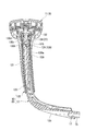
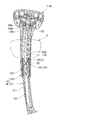
図1~図4に示すように、背凭れ支持杆7の前向部7bにおける上向突片7cよりさらに後方で、かつ前向部7bの前後方向の中間部には、肘掛け装置9が設けられている。
As shown in FIGS. 1 to 4, an armrest device 9 is provided in the forward portion 7 b of the backrest supporting rod 7 further behind the upward projecting piece 7 c and in the middle portion in the front-rear direction of the forward portion 7 b. It has been.
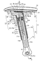
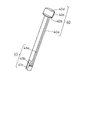
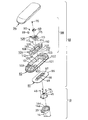
肘掛け装置9は、肘掛け支柱10とその上端に取り付けられた肘掛け11とからなる。
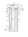
肘掛け支柱10は、上下方向を向く起立部12a(支持体)の下端より内側方よりわずかに下方を向く内向部12bが連設されることにより正面視ほぼL字状をなす下部支持杆12(支持体)と、その起立部12aに、高さ調節装置13をもって、高さ調節能として装着された上部支持筒14とからなり、肘掛け11は、上部支持筒14の上端に取り付けられている。 Thearmrest device 9 includes an armrest column 10 and an armrest 11 attached to the upper end thereof.
Thearmrest strut 10 has a lower support rod 12 (substantially L-shaped when viewed from the front by continuously connecting an inward portion 12b facing slightly downward from the lower end of an upright portion 12a (support) facing upward and downward. A support body) and an upper support cylinder 14 mounted on the upright portion 12a as a height adjustment device with a height adjustment device 13. The armrest 11 is attached to the upper end of the upper support cylinder 14.
肘掛け支柱10は、上下方向を向く起立部12a(支持体)の下端より内側方よりわずかに下方を向く内向部12bが連設されることにより正面視ほぼL字状をなす下部支持杆12(支持体)と、その起立部12aに、高さ調節装置13をもって、高さ調節能として装着された上部支持筒14とからなり、肘掛け11は、上部支持筒14の上端に取り付けられている。 The
The
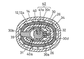
下部支持杆12における内向部12bは、前後方向に長い楕円形断面をなして、内方(支基6側)に向かって漸次断面積が拡大している。内向部12bの内端面には、側面形が前後方向に長い長円形または楕円形をなし、平面形が中央に縦溝15aを有する二股状をなす内向突部15が形成されている。
The inward portion 12b of the lower support rod 12 has an elliptical cross section that is long in the front-rear direction, and the cross-sectional area gradually increases inward (toward the support base 6). On the inner end surface of the inward portion 12b, there is formed an inward protrusion 15 having a bifurcated shape in which the side shape is an oval or an ellipse that is long in the front-rear direction and the planar shape has a longitudinal groove 15a in the center.
下部支持杆12の内向部12bの下面における外端部から内端近くにかけては、後述するボルト20の頭部20aを挿入し易くするための凹部16が形成されている。
また、内向部12b内には、内向突部15における縦溝15aの中央部に開口するボルト挿通孔17が左右方向(内向部12bの延設方向)に向け設けられている。 Arecess 16 for facilitating insertion of a head 20a of a bolt 20 described later is formed from the outer end to the vicinity of the inner end of the lower surface of the inward portion 12b of the lower support rod 12.
Further, in theinward portion 12b, a bolt insertion hole 17 that opens at the center portion of the longitudinal groove 15a in the inward protrusion 15 is provided in the left-right direction (the extending direction of the inward portion 12b).
また、内向部12b内には、内向突部15における縦溝15aの中央部に開口するボルト挿通孔17が左右方向(内向部12bの延設方向)に向け設けられている。 A
Further, in the
背凭れ支持杆7の前向部7bにおける上向突片7cよりさらに後方の下部支持杆12の取付部には、内向突部15が嵌合される凹部18が設けられており、内向突部15の縦溝15aに嵌合する上下方向を向く突条18aの外端面には、雌ねじ孔19が設けられている。
The mounting portion of the lower support rod 12 further rearward than the upward projecting piece 7c of the forward support portion 7b of the backrest support rod 7 is provided with a concave portion 18 into which the inward projection portion 15 is fitted. A female screw hole 19 is provided on the outer end surface of the ridge 18a facing in the up-down direction and fitted in the 15 vertical grooves 15a.
この状態で、内向突部15を凹部18に嵌合することにより、下部支持杆12の内向部12bの内端面が背凭れ支持杆7の前向部7bの外側面に当接する。ボルト20の頭部20aが凹部16内に位置するようにして、ボルト20の軸部20bをボルト挿通孔17に挿通し、かつボルト20の雄ねじ部20cを、背凭れ支持杆7の前向部7bにおける雌ねじ孔19に螺合して締め付ける。その結果、下部支持杆12は、背凭れ支持杆7に、前後左右に位置ずれすることなく、強固に固着され、下部支持杆12の起立部12aは、座4の側方において起立している。
In this state, by fitting the inward projection 15 into the recess 18, the inner end surface of the inward portion 12b of the lower support rod 12 comes into contact with the outer surface of the forward portion 7b of the backrest support rod 7. The shaft 20b of the bolt 20 is inserted into the bolt insertion hole 17 so that the head 20a of the bolt 20 is positioned in the recess 16, and the male threaded portion 20c of the bolt 20 is connected to the forward portion of the backrest support rod 7. It is screwed into the female screw hole 19 in 7b and tightened. As a result, the lower support rod 12 is firmly fixed to the backrest support rod 7 without being displaced in the front-rear and left-right directions, and the standing portion 12a of the lower support rod 12 stands on the side of the seat 4. .
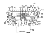
下部支持杆12の起立部12aの外形は、前後方向に長い楕円形断面をなし、その上端に、凹入段部21が形成されることにより、起立部12aの上端部は筒状をなしている。
凹入段部21の底面21aの中央には、起立部12aの下端部まで至る凹孔21bが設けられている。 The outer shape of theupright portion 12a of the lower support rod 12 has an elliptical cross section that is long in the front-rear direction, and the upper end portion of the upright portion 12a has a cylindrical shape by forming a recessed stepped portion 21 at the upper end. Yes.
In the center of thebottom surface 21a of the recessed stepped portion 21, a recessed hole 21b extending to the lower end portion of the standing portion 12a is provided.
凹入段部21の底面21aの中央には、起立部12aの下端部まで至る凹孔21bが設けられている。 The outer shape of the
In the center of the
下部支持杆12の起立部12aの上部前面には、凹入段部21に連通する方形の窓孔22が設けられている。
また、下部支持杆12の起立部12aの上部における両側部には、前後1対の係合孔23、23が設けられている。 Arectangular window hole 22 communicating with the recessed stepped portion 21 is provided on the upper front surface of the upright portion 12 a of the lower support rod 12.
Further, a pair of front and rear engagement holes 23, 23 are provided on both sides of the upper portion of theupright portion 12a of the lower support rod 12.
また、下部支持杆12の起立部12aの上部における両側部には、前後1対の係合孔23、23が設けられている。 A
Further, a pair of front and rear engagement holes 23, 23 are provided on both sides of the upper portion of the
下部支持杆12の起立部12aの上端部には、中央に上下方向を向く挿通孔24が設けられた閉塞板25の下面に、左右1対の垂下側片26、26が設けられたエンドキャップ27が、垂下側片26、26が凹入段部21内に嵌合し、かつ閉塞板25の下面が起立部12aの上端面に当接するように装着されている。
An end cap provided with a pair of left and right hanging pieces 26, 26 on the lower surface of a closing plate 25 provided with an insertion hole 24 facing the vertical direction at the center at the upper end of the upright portion 12 a of the lower support rod 12. 27 is mounted such that the drooping side pieces 26, 26 are fitted in the recessed stepped portion 21, and the lower surface of the closing plate 25 is in contact with the upper end surface of the standing portion 12a.
エンドキャップ27が下部支持杆12の起立部12aの上端部に装着された状態において、下部支持杆12の起立部12aの上端部における左右方向を貫通する係合孔23、23と、それらと同軸上に設けられた左右の垂下側片26、26に設けられた係合孔28、28とには、左右方向を向くピン29が嵌合され、エンドキャップ27は、下部支持杆12の起立部12aの上端部から抜け止めされている。
In a state where the end cap 27 is attached to the upper end portion of the upright portion 12a of the lower support rod 12, engagement holes 23 and 23 penetrating in the left-right direction at the upper end portion of the upright portion 12a of the lower support rod 12 are coaxial with them. Pins 29 facing in the left-right direction are fitted into the engagement holes 28, 28 provided in the left and right hanging side pieces 26, 26 provided above, and the end cap 27 is an upright portion of the lower support rod 12. It is prevented from coming off from the upper end of 12a.
下部支持杆12の起立部12aの上端部における凹入段部21の底面21aと、エンドキャップ27における閉塞板25の下面と、左右の両垂下側片26、26とにより囲まれた空間内には、ロック部材30が、前後方向に摺動可能に嵌合されている。
In a space surrounded by the bottom surface 21 a of the recessed step portion 21 at the upper end of the upright portion 12 a of the lower support rod 12, the lower surface of the closing plate 25 in the end cap 27, and the left and right hanging side pieces 26, 26. The lock member 30 is slidably fitted in the front-rear direction.
図2~図4、および図6に示すように、ロック部材30は、中央部に、上下方向を向き、かつ前後方向に長い長円形の挿通孔31が設けられたほぼ長円筒形の胴部30aの前端に、下部支持杆12の起立部12aの上端部における窓孔22を通って起立部12aの前面より進退可能な係合突部30bが設けられている。挿通孔31の内面における左右いずれかに、内方を向く突部30cが設けられ、さらに、胴部30aの後面に、ばね受け用突部30dが設けられたものよりなっている。係合突部30bの下面は、前上方を向く傾斜面をなしている。
As shown in FIG. 2 to FIG. 4 and FIG. 6, the lock member 30 has a substantially cylindrical body having an oval insertion hole 31 that is oriented in the vertical direction and is long in the front-rear direction. At the front end of 30a, there is provided an engaging projection 30b that can be advanced and retracted from the front surface of the standing portion 12a through the window hole 22 in the upper end portion of the standing portion 12a of the lower support rod 12. A protrusion 30c facing inward is provided on either the left or right side of the inner surface of the insertion hole 31, and a spring receiving protrusion 30d is provided on the rear surface of the body 30a. The lower surface of the engagement protrusion 30b forms an inclined surface facing the front upper side.
ロック部材30の胴部30aの後面と、下部支持杆12の起立部12aの上端部における凹入段部21内の後壁部分の前面との間には、前後方向を向く付勢手段である圧縮コイルばね32が、圧縮された状態で、その前端部がばね受け用突部30dに嵌合している。
Between the rear surface of the trunk portion 30a of the lock member 30 and the front surface of the rear wall portion in the recessed stepped portion 21 at the upper end portion of the upright portion 12a of the lower support rod 12, there is an urging means that faces in the front-rear direction. The compression coil spring 32 is in a compressed state, and its front end is fitted to the spring receiving projection 30d.
ロック部材30は、この圧縮コイルばね32により、前方に向けて付勢され、通常は、係合突部30bが窓孔22を通って起立部12aの前面より突出するロック位置に位置している。ロック部材30は、後述する回動杆40(作動部材)によって、後方に向けて押されることにより、係合突部30bが窓孔22内に没入するアンロック位置に移動する。
The lock member 30 is urged forward by the compression coil spring 32, and is normally positioned at a lock position where the engagement protrusion 30b protrudes from the front surface of the standing part 12a through the window hole 22. . When the locking member 30 is pushed rearward by a rotating rod 40 (operation member) described later, the locking protrusion 30b moves to an unlock position where the engaging protrusion 30b enters the window hole 22.
上部支持筒14は、前後方向に長い楕円形の筒状をなし、上端部に、上方に向かって断面積が拡大し、特に前方に向かって長く張り出す拡大部14aを備えている。拡大部14aの前部には、後述する操作レバー43(操作部材)の一部が挿通する窓孔33が設けられている。また、上部支持筒14の下端部には、内向鍔部14bが設けられている。さらに、拡大部14aの上面には、浅い凹入段部14cが形成されている。
The upper support cylinder 14 has an elliptical cylindrical shape that is long in the front-rear direction, and has an enlarged portion 14 a that has a cross-sectional area that expands upward and extends particularly forward in the upper end. A window hole 33 through which a part of an operation lever 43 (operation member) described later is inserted is provided at the front portion of the enlarged portion 14a. Further, an inward flange portion 14 b is provided at the lower end portion of the upper support cylinder 14. Further, a shallow recessed step 14c is formed on the upper surface of the enlarged portion 14a.
上部支持筒14内には、下部支持杆12の起立部12aに上下方向に摺動可能として外嵌された内筒体34が内嵌されている。
内筒体34の上部には、それより下方の部分よりわずかに拡大する拡大段部34aが形成されており、その内部の凹入段部35の底壁35aの中央には、後述する回動杆40が挿通する挿通孔36が設けられている。 Inside theupper support cylinder 14 is fitted an inner cylinder 34 that is externally fitted to the upright portion 12a of the lower support rod 12 so as to be slidable in the vertical direction.
In the upper part of the innercylindrical body 34, an enlarged step part 34a that is slightly enlarged from the part below it is formed, and in the center of the bottom wall 35a of the recessed step part 35 inside, there is a rotation described later. An insertion hole 36 through which the flange 40 is inserted is provided.
内筒体34の上部には、それより下方の部分よりわずかに拡大する拡大段部34aが形成されており、その内部の凹入段部35の底壁35aの中央には、後述する回動杆40が挿通する挿通孔36が設けられている。 Inside the
In the upper part of the inner
拡大段部34aの前面には、操作レバー43の一部が前後方向に挿通する縦溝37が設けられ、その後方における凹入段部35の左右の内側面に設けた上下方向を向くリブ35b、35bの内側面には、操作レバー43の枢軸44を受支する、上端が開口するU字状溝38、38が設けられている。
A longitudinal groove 37 through which a part of the operation lever 43 is inserted in the front-rear direction is provided on the front surface of the enlarged step part 34a, and a rib 35b facing the up-down direction provided on the left and right inner side surfaces of the recessed step part 35 at the rear. , 35b are provided with U-shaped grooves 38, 38 for receiving the pivot 44 of the operation lever 43 and having an open upper end.
内筒体34における拡大段部34aより下方の部分における前面には、複数の方形の係合孔39が、上下方向に並べて設けられている。各係合孔39の下縁は、後下方を向く傾斜面をなしている。
A plurality of rectangular engagement holes 39 are arranged in the vertical direction on the front surface of the inner cylinder 34 below the enlarged step 34a. The lower edge of each engagement hole 39 forms an inclined surface facing rearward and downward.
回動杆40は、上部支持筒14および内筒体34と同芯をなす円柱状の軸部40aの上端に大径の円板部40bを連設し、さらにその上に半円弧状とした被操作部40cを連設して形成されている。図5に示すように、軸部40aの外周面には、円板部40bの直下から軸部40aの下端近傍まで至る上下方向の縦溝41aと、縦溝41aの下端部より軸部40aの円周方向を向く横溝41bと、横溝41bにおける縦溝41aとの連設端部と反対側の端部から軸部40aの下端までに至る上下方向の縦溝41cとからなるクランク状の凹溝41が設けられている。
The rotary rod 40 has a large-diameter disk portion 40b connected to the upper end of a columnar shaft portion 40a concentric with the upper support cylinder 14 and the inner cylinder 34, and further has a semicircular arc shape thereon. The operated portion 40c is formed continuously. As shown in FIG. 5, on the outer peripheral surface of the shaft portion 40a, the vertical groove 41a in the vertical direction extending from directly below the disc portion 40b to the vicinity of the lower end of the shaft portion 40a, and the shaft portion 40a from the lower end portion of the vertical groove 41a. Crank-shaped concave groove comprising a horizontal groove 41b facing in the circumferential direction, and a vertical groove 41c in the vertical direction extending from the opposite end of the horizontal groove 41b to the lower end of the shaft portion 40a. 41 is provided.
被操作部40cにおける半円弧の弦となる平削面は、回動杆40の中心軸線と平行をなし、後述する操作レバー43の作動部43bが当接する当接面40dを形成する。
The planing surface serving as a semicircular chord in the operated portion 40c is parallel to the central axis of the rotary rod 40, and forms an abutting surface 40d on which an operating portion 43b of the operating lever 43, which will be described later, abuts.
回動杆40は、円板部40bの下面が、内筒体34の底壁35aの上面に当接し、縦溝41aにロック部材30の突部30cが相対移動可能に嵌合するように、軸部40aが、内筒体34の底壁35aの挿通孔36と、エンドキャップ27における閉塞板25の挿通孔24と、ロック部材30の挿通孔31とを通って、下部支持杆12の起立部12aの凹孔21b内に回動可能に挿入されている。
The rotary rod 40 has a lower surface of the disc portion 40b that abuts on an upper surface of the bottom wall 35a of the inner cylinder 34, and the protrusion 30c of the lock member 30 is fitted to the vertical groove 41a so as to be relatively movable. The shaft portion 40 a passes through the insertion hole 36 of the bottom wall 35 a of the inner cylinder 34, the insertion hole 24 of the closing plate 25 in the end cap 27, and the insertion hole 31 of the lock member 30, so that the lower support rod 12 rises. It is rotatably inserted into the concave hole 21b of the portion 12a.
回動杆40における縦溝41aと、ロック部材30における突部30cとにより、回動杆40の一方向への回動により、ロック部材30をアンロック位置方向へ移動させるように、回動杆40とロック部材30とを連係する連係機構42が形成されている。
The pivot rod 41 is moved in the unlock position direction by the pivot groove 40 in one direction by the vertical groove 41a in the pivot rod 40 and the protrusion 30c in the lock member 30. A linkage mechanism 42 that links 40 and the lock member 30 is formed.
すなわち、図6に示すように、ロック部材30がロック位置に位置している状態から、回動杆40を、図6における時計回りに回動させると、縦溝41aの前方に位置する側面が作動部となって、突部30cを後方に押し、それによって、ロック部材30は、圧縮コイルばね32の付勢力に抗して、後方に移動し、アンロック位置となる。
That is, as shown in FIG. 6, when the rotary rod 40 is rotated clockwise in FIG. 6 from the state where the lock member 30 is located at the lock position, the side surface located in front of the vertical groove 41a is It becomes an operation part and pushes the protrusion 30c backward, whereby the lock member 30 moves backward against the urging force of the compression coil spring 32 and becomes the unlock position.
上述のように、凹溝41(作用部)をクランク状としたのは、肘掛け11とともに上部支持筒14を上限まで持ち上げた際に、ロック部材30の突部30cが縦溝41aの下端に当接して、上部支持筒14のそれ以上の上昇を阻止するため、及び、回動杆40を、挿入途中で中心軸線回りに若干回動させることにより、下部支持杆12の起立部12a内に出し入れできるようにするためである。
As described above, the concave groove 41 (acting portion) has a crank shape because when the upper support cylinder 14 is lifted up to the upper limit together with the armrest 11, the protrusion 30c of the lock member 30 contacts the lower end of the vertical groove 41a. In contact therewith, the upper support cylinder 14 is prevented from further rising, and the pivot rod 40 is slightly rotated about the central axis during the insertion, so that it can be taken in and out of the standing portion 12a of the lower support rod 12. This is to make it possible.
操作レバー43は、操作レバー43の前後方向の中間部を左右方向に貫通する枢軸44の両端部を、内筒体34における左右のU字状溝38、38内に上方より挿入することにより、内筒体34の凹入段部35内に回動自在に装着され、前部の操作部43aが、内筒体34の縦溝37、および上部支持筒14の窓孔33を通って、窓孔33より下方に向かって突出する。
The operation lever 43 is inserted from above into the left and right U-shaped grooves 38, 38 of the inner cylinder 34 by inserting both end portions of the pivot 44 passing through the middle portion in the front-rear direction of the operation lever 43 in the left-right direction. It is rotatably mounted in the recessed step portion 35 of the inner cylinder 34, and the front operation portion 43 a passes through the vertical groove 37 of the inner cylinder 34 and the window hole 33 of the upper support cylinder 14, and opens the window. It protrudes downward from the hole 33.
操作レバー43における枢軸44より後方の作動部43bは、側面視でフック状であり後方に突出するとともに、その先端部が回動杆40の中心軸線より側方に偏っており、図7に示すように、回動杆40の被操作部40cにおける当接面40dの偏心部に後方より当接している。
The operating portion 43b of the operation lever 43 behind the pivot 44 is hook-like in a side view and protrudes rearward, and its tip is biased laterally from the central axis of the rotary rod 40, as shown in FIG. As described above, the eccentric part of the contact surface 40d of the operated part 40c of the rotating rod 40 is in contact with the rear part.
上部支持筒14の上端における凹入段部14cには、閉塞部材45が嵌合され、止めねじ46により固定されている。閉塞部材45の上面におけるほぼ中央部には、上向突部47が突設しており、上向突部47を用いることで、閉塞部材45上に、肘掛け11が装着されている。
閉塞部材45の上面および上部支持筒14の上端面は、肘掛け11を支持する受支面であり、上向突部47は、受支面より上方に突出する肘掛け支柱10の上端部である。 A closingmember 45 is fitted into the recessed step 14 c at the upper end of the upper support cylinder 14 and is fixed by a set screw 46. An upward protrusion 47 projects from substantially the center of the upper surface of the closing member 45, and the armrest 11 is mounted on the closing member 45 by using the upward protrusion 47.
The upper surface of the closingmember 45 and the upper end surface of the upper support cylinder 14 are support surfaces that support the armrest 11, and the upward protrusion 47 is the upper end portion of the armrest column 10 that protrudes upward from the support surface.
閉塞部材45の上面および上部支持筒14の上端面は、肘掛け11を支持する受支面であり、上向突部47は、受支面より上方に突出する肘掛け支柱10の上端部である。 A closing
The upper surface of the closing
内筒体34は、この閉塞部材45と上部支持筒14の内向鍔部14bとにより上下から挟まれることによって、上部支持筒14から外れ止めされ、かつ楕円形の上部支持筒14内に密接状態で内嵌されることにより、上部支持筒14に対して回り止めされている。
The inner cylinder 34 is prevented from coming off from the upper support cylinder 14 by being sandwiched from above and below by the closing member 45 and the inward flange portion 14 b of the upper support cylinder 14, and is in close contact with the elliptical upper support cylinder 14. By being internally fitted, it is prevented from rotating with respect to the upper support cylinder 14.
また、回動杆40や操作レバー43も、閉塞部材45によって、上部支持筒14および内筒体34から外れ止めされている。
The rotating rod 40 and the operation lever 43 are also prevented from coming off from the upper support cylinder 14 and the inner cylinder 34 by the closing member 45.
通常、ロック部材30は、圧縮コイルばね32の付勢力により前方に向けて付勢され、係合突部30bが内筒体34のいずれかの係合孔39に係合したロック位置に位置していることにより、内筒体34と、内筒体34と一体となっている上部支持筒14および肘掛け11は、適宜の高さに保持されている。
Normally, the lock member 30 is urged forward by the urging force of the compression coil spring 32, and the engagement protrusion 30 b is positioned at the lock position where it is engaged with any of the engagement holes 39 of the inner cylinder 34. Accordingly, the inner cylinder 34, and the upper support cylinder 14 and the armrest 11 integrated with the inner cylinder 34 are held at appropriate heights.
この状態から、肘掛け11の高さを変更したいときは、操作レバー43の操作部43aを、圧縮コイルばね32の付勢力に抗して、上向きに押し上げる。
すると、枢軸44を中心として、操作レバー43の作動部43bが下向きに回動し、その先端で、回動杆40の被操作部40cにおける当接面40dの偏心部を前方に押す。そのため、回動杆40は、図7および図6における時計回りに回動し、縦溝41aの前方の内側面である作動部によって、ロック部材30の突部30cを後方に押す。従って、ロック部材30は、圧縮コイルばね32の付勢力に抗して、後方に移動し、アンロック位置となる。 When it is desired to change the height of the armrest 11 from this state, theoperation portion 43a of the operation lever 43 is pushed upward against the urging force of the compression coil spring 32.
Then, the actuatingportion 43b of the operation lever 43 is rotated downward about the pivot 44, and the eccentric portion of the contact surface 40d of the operated portion 40c of the rotating rod 40 is pushed forward at the tip thereof. Therefore, the rotating rod 40 rotates clockwise in FIGS. 7 and 6 and pushes the protrusion 30c of the lock member 30 rearward by the operating portion which is the inner surface in front of the vertical groove 41a. Therefore, the lock member 30 moves rearward against the urging force of the compression coil spring 32 and enters the unlock position.
すると、枢軸44を中心として、操作レバー43の作動部43bが下向きに回動し、その先端で、回動杆40の被操作部40cにおける当接面40dの偏心部を前方に押す。そのため、回動杆40は、図7および図6における時計回りに回動し、縦溝41aの前方の内側面である作動部によって、ロック部材30の突部30cを後方に押す。従って、ロック部材30は、圧縮コイルばね32の付勢力に抗して、後方に移動し、アンロック位置となる。 When it is desired to change the height of the armrest 11 from this state, the
Then, the actuating
ロック部材30がアンロック位置まで後退すると、ロック部材30の係合突部30bが、嵌合していた内筒体34の係合孔39から離脱し、肘掛け11および上部支持筒14は、下部支持杆12の起立部12aに対して上下方向に自由に移動できるようになる。
When the lock member 30 is retracted to the unlock position, the engagement protrusion 30b of the lock member 30 is disengaged from the engagement hole 39 of the fitted inner cylinder 34, and the armrest 11 and the upper support cylinder 14 It becomes possible to move freely in the vertical direction with respect to the standing portion 12a of the support rod 12.
肘掛け11を所望の高さまで移動させた後、操作レバー43の操作部43aから手を離すと、ロック部材30は、圧縮コイルばね32の付勢力により、前方に向けて押され、ロック部材30の係合突部30bは、内筒体34のいずれかの係合孔39に嵌合するか、または先端が内筒体34の内面に当接して停止する。
After moving the armrest 11 to a desired height, when the hand is released from the operation portion 43 a of the operation lever 43, the lock member 30 is pushed forward by the urging force of the compression coil spring 32, and the lock member 30 The engaging protrusion 30b is fitted into any of the engaging holes 39 of the inner cylinder 34, or the distal end abuts against the inner surface of the inner cylinder 34 and stops.
後者の場合は、その後肘掛け11を上方または下方のいずれかにわずかに移動させるだけで、係合突部30bは、最も近い係合孔39に嵌合する。
In the latter case, the engagement protrusion 30b is fitted into the closest engagement hole 39 only by moving the armrest 11 slightly upward or downward.
ロック部材30の係合突部30bが、内筒体34のいずれかの係合孔39に嵌合し、ロック部材30がロック位置で停止すると、内筒体34と、それと一体の上部支持筒14および肘掛け11は、そのときの高さに保持される。
When the engagement protrusion 30b of the lock member 30 is fitted into any of the engagement holes 39 of the inner cylinder 34 and the lock member 30 stops at the lock position, the inner cylinder 34 and the upper support cylinder integral with the inner cylinder 34 are obtained. 14 and the armrest 11 are held at the height at that time.
また、肘掛け11を上方に引き上げたいときは、肘掛け11を上方に持ち上げるだけでよい。このときの内筒体34の上昇により、ロック部材30の係合突部30bが係合している係合孔39の下縁の傾斜面が、係合突部30bの下縁の傾斜面を後方に向かって押し、ロック部材30を、圧縮コイルばね32の付勢力に抗して、アンロック位置まで移動させる。係合突部30bが、それまで係合していた係合孔39の次段の係合孔39に係合すると、ロック部材30は、圧縮コイルばね32の付勢力により、再度ロック位置まで移動し、その後、同じ動作を繰り返すことにより、肘掛け11を、係合孔39の一段毎に上昇させることができる。
Also, when it is desired to lift the armrest 11 upward, it is only necessary to lift the armrest 11 upward. As the inner cylindrical body 34 is raised at this time, the inclined surface of the lower edge of the engaging hole 39 engaged with the engaging protrusion 30b of the lock member 30 becomes the inclined surface of the lower edge of the engaging protrusion 30b. Pushing backward, the locking member 30 is moved to the unlocked position against the biasing force of the compression coil spring 32. When the engagement protrusion 30b is engaged with the engagement hole 39 of the next stage of the engagement hole 39 that has been engaged so far, the lock member 30 is moved again to the lock position by the urging force of the compression coil spring 32. Then, the armrest 11 can be raised for each stage of the engagement hole 39 by repeating the same operation.
肘掛け11が上限に達すると、ロック部材30の突部30cが、凹溝41における縦溝41aの下端に当接して、肘掛け11のそれ以上の上昇が阻止される。
When the armrest 11 reaches the upper limit, the protrusion 30c of the lock member 30 comes into contact with the lower end of the vertical groove 41a in the concave groove 41, and the armrest 11 is prevented from further rising.
この肘掛け装置9においては、回動杆40は、肘掛け11とともに、ロック部材30に対して上下方向に移動するだけで、回動杆40とロック部材30と連係機構42との関係は何ら変動することはない。よって、肘掛け11がどのような高さに位置していても、常に同一の条件で、軽快にロックおよびロック解除操作をすることができる。
しかも、回動杆40とロック部材30と連係機構42との関係が変動することがないので、誤操作および誤作動の可能性を少なくすることができる。
また、肘掛け11の移動ストロークを大としても、肘掛け11全体の上下方向の長さを大とする必要がないので、肘掛け装置9の小型化、および材料費の削減を図ることができるとともに、椅子への肘掛け装置9の取付位置の自由度を増すことができる。 In thisarmrest device 9, the pivot rod 40 moves together with the armrest 11 in the vertical direction with respect to the lock member 30, and the relationship between the pivot rod 40, the lock member 30, and the linkage mechanism 42 changes at all. There is nothing. Therefore, no matter what height the armrest 11 is positioned, the locking and unlocking operations can be easily performed under the same conditions.
In addition, since the relationship among the rotatingrod 40, the lock member 30, and the linkage mechanism 42 does not fluctuate, the possibility of erroneous operations and malfunctions can be reduced.
Further, even if the movement stroke of thearmrest 11 is increased, it is not necessary to increase the length of the entire armrest 11 in the vertical direction. Therefore, the armrest device 9 can be reduced in size and the material cost can be reduced, and the chair can be reduced. The degree of freedom of the mounting position of the armrest device 9 can be increased.
しかも、回動杆40とロック部材30と連係機構42との関係が変動することがないので、誤操作および誤作動の可能性を少なくすることができる。
また、肘掛け11の移動ストロークを大としても、肘掛け11全体の上下方向の長さを大とする必要がないので、肘掛け装置9の小型化、および材料費の削減を図ることができるとともに、椅子への肘掛け装置9の取付位置の自由度を増すことができる。 In this
In addition, since the relationship among the rotating
Further, even if the movement stroke of the
以上の構成のうち、下部支持杆12が什器における支持体となり、上部支持筒14が、上記支持体に、上下方向に移動可能として装着された移動部材となり、内筒体34が、移動部材である上部支持筒14に固着され、かつ上下方向に配置された複数の係合孔39からなる係合部が設けられた上下方向を向くガイド部材となる。それらと、ロック部材30、圧縮コイルばね32よりなる付勢手段、回動杆40、連係機構42、および操作レバー43とにより、什器における高さ調節装置13が形成されている。
Of the above configuration, the lower support rod 12 is a support body in the fixture, the upper support cylinder 14 is a moving member mounted on the support body so as to be movable in the vertical direction, and the inner cylinder body 34 is a moving member. It becomes a guide member which faces to the up-down direction provided with the engaging part which is fixed to a certain upper support cylinder 14 and is provided with a plurality of engaging holes 39 arranged in the up-down direction. These, the biasing means including the lock member 30 and the compression coil spring 32, the rotating rod 40, the linkage mechanism 42, and the operation lever 43 form the height adjusting device 13 in the fixture.
次に、肘掛け装置9における肘掛け11の構成を詳細に説明する。
図2および図8~図12に示すように、肘掛け11は、上述した閉塞部材45により支持された遮蔽部材を兼ねる肘掛け支持板50と、この肘掛け支持板50により支持された肘掛け基板51と、この肘掛け支持板50および肘掛け基板51を、水平方向に移動可能かつ上方に移動不能として肘掛け支柱10の上端面との間に挾持する保持手段71と、この保持手段71と肘掛け基板51の上面を覆うようにして、肘掛け基板51に装着した、エラストマー等よりなる肘当て52とを備えている。受支面である閉塞部材45の上面より起立し、かつ肘掛け支柱10の上端部をなす上述の上向突部47は、パイプより形成され、その下端部を閉塞部材45に穿設された貫通孔53に圧嵌するか、または溶接等により固着することにより、閉塞部材45の上面に突設されている。上向突部47の上端には、四角ナット54が、溶接等により固着されている。 Next, the configuration of the armrest 11 in thearmrest device 9 will be described in detail.
As shown in FIGS. 2 and 8 to 12, thearmrest 11 includes an armrest support plate 50 also serving as a shielding member supported by the above-described closing member 45, an armrest substrate 51 supported by the armrest support plate 50, The holding means 71 that holds the armrest support plate 50 and the armrest substrate 51 between the upper end surfaces of the armrest struts 10 so that the armrest support plate 50 and the armrest substrate 51 can move in the horizontal direction and cannot move upward, An elbow rest 52 made of an elastomer or the like is attached to the armrest substrate 51 so as to cover it. The above-described upward protrusion 47 that stands from the upper surface of the closing member 45 that is a receiving surface and that forms the upper end of the armrest strut 10 is formed of a pipe, and the lower end is a through-hole formed in the closing member 45. It is protruded from the upper surface of the closing member 45 by being press-fitted into the hole 53 or fixed by welding or the like. A square nut 54 is fixed to the upper end of the upward projection 47 by welding or the like.
図2および図8~図12に示すように、肘掛け11は、上述した閉塞部材45により支持された遮蔽部材を兼ねる肘掛け支持板50と、この肘掛け支持板50により支持された肘掛け基板51と、この肘掛け支持板50および肘掛け基板51を、水平方向に移動可能かつ上方に移動不能として肘掛け支柱10の上端面との間に挾持する保持手段71と、この保持手段71と肘掛け基板51の上面を覆うようにして、肘掛け基板51に装着した、エラストマー等よりなる肘当て52とを備えている。受支面である閉塞部材45の上面より起立し、かつ肘掛け支柱10の上端部をなす上述の上向突部47は、パイプより形成され、その下端部を閉塞部材45に穿設された貫通孔53に圧嵌するか、または溶接等により固着することにより、閉塞部材45の上面に突設されている。上向突部47の上端には、四角ナット54が、溶接等により固着されている。 Next, the configuration of the armrest 11 in the
As shown in FIGS. 2 and 8 to 12, the
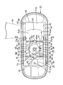
肘掛け支持板50は、前後寸法が、上部支持筒14の上面の前後方向の長さよりも十分に大きく、かつ左右寸法が、肘掛け基板51の幅とほぼ同等の前後方向に長い概ね長方形の閉塞板50aを有する。この閉塞板50aの中央部の上面には、肘掛け基板51を、第2方向である前後方向に案内するためのガイド突部55が、一体的に上向きに突設されている。このガイド突部55は、左右幅が閉塞部材45の左右寸法とほぼ等しく、かつ上下寸法が肘掛け基板51の底面板51aの厚さとほぼ等しい平面視概ね方形をなす。ガイド突部55の両側面には、互いに平行な前後方向に長いガイド面(摺接面)55a、55aを有する。
The armrest support plate 50 has a substantially rectangular obstruction plate whose front-rear dimension is sufficiently larger than the length of the upper surface of the upper support cylinder 14 in the front-rear direction and whose left-right dimension is long in the front-rear direction substantially the same as the width of the armrest substrate 51. 50a. On the upper surface of the central portion of the closing plate 50a, a guide projection 55 for guiding the armrest substrate 51 in the front-rear direction, which is the second direction, is integrally projected upward. The guide protrusion 55 has a substantially rectangular shape in plan view, with a lateral width substantially equal to the lateral dimension of the closing member 45 and a vertical dimension substantially equal to the thickness of the bottom plate 51 a of the armrest substrate 51. On both side surfaces of the guide protrusion 55, there are long guide surfaces (sliding contact surfaces) 55a, 55a parallel to each other in the front-rear direction.
ガイド突部55の中央部には、左右方向を向く長孔56が、上下に貫通して形成され、長孔56の上面の開口縁には、短寸の縁片57が上向きに突設されている。
ガイド突部55の長孔56に閉塞部材45の上向突部47を相対移動可能に嵌合することにより、肘掛け支持板50は、左右方向に移動可能かつ上向突部47回りに水平回動可能に、上部支持筒14の上端の閉塞部材45の上面に支持される。なお、長孔56に上向突部47を相対移動可能に嵌合した際、四角ナット54を含む上向突部47の上端部が、ガイド突部55の上面より若干突出する。また、長孔56の左右方向の長さは、上向突部47が長孔56の端部に当接する限界位置まで肘掛け支持板50が移動したときでも、長孔56が閉塞部材45の上端面より側方に突出しないように定めてある。 Along hole 56 facing in the left-right direction is formed at the center of the guide protrusion 55 so as to penetrate in the vertical direction. A short edge piece 57 protrudes upward from the opening edge of the upper surface of the long hole 56. ing.
By fitting theupward protrusion 47 of the closing member 45 into the elongated hole 56 of the guide protrusion 55 so as to be relatively movable, the armrest support plate 50 can move in the left-right direction and rotate horizontally around the upward protrusion 47. It is supported on the upper surface of the closing member 45 at the upper end of the upper support cylinder 14 so as to be movable. When the upward protrusion 47 is fitted in the long hole 56 so as to be relatively movable, the upper end portion of the upward protrusion 47 including the square nut 54 slightly protrudes from the upper surface of the guide protrusion 55. Further, the length of the long hole 56 in the left-right direction is such that the long hole 56 is above the closing member 45 even when the armrest support plate 50 is moved to a limit position where the upward protrusion 47 abuts the end of the long hole 56. It is determined not to protrude from the end face to the side.
ガイド突部55の長孔56に閉塞部材45の上向突部47を相対移動可能に嵌合することにより、肘掛け支持板50は、左右方向に移動可能かつ上向突部47回りに水平回動可能に、上部支持筒14の上端の閉塞部材45の上面に支持される。なお、長孔56に上向突部47を相対移動可能に嵌合した際、四角ナット54を含む上向突部47の上端部が、ガイド突部55の上面より若干突出する。また、長孔56の左右方向の長さは、上向突部47が長孔56の端部に当接する限界位置まで肘掛け支持板50が移動したときでも、長孔56が閉塞部材45の上端面より側方に突出しないように定めてある。 A
By fitting the
ガイド突部55の前方において、肘掛け支持板50の左右方向の中央部上面には、後述する下部保持部材67を連結するための前後方向を向く上向突片58が、上向きに突設されている。上向突片58の後端はガイド突部55の前面に連結されている。上向突片58の前部の上下寸法は、後部よりも大とされ、上向突片58の前部の上半部には、その板厚よりも大径をなすとともに、上下方向の雌ねじ孔59を有する軸状の拡幅部58aが形成されている。
In front of the guide protrusion 55, an upper protrusion 58 that faces in the front-rear direction for connecting a lower holding member 67, which will be described later, protrudes upward on the upper surface of the central portion in the left-right direction of the armrest support plate 50. Yes. The rear end of the upward protruding piece 58 is connected to the front surface of the guide protruding portion 55. The vertical dimension of the front part of the upward projecting piece 58 is made larger than that of the rear part, and the upper half of the front part of the upward projecting piece 58 has a diameter larger than its plate thickness, and has a female screw in the vertical direction. A shaft-shaped widened portion 58 a having a hole 59 is formed.
肘掛け基板51は、平面形が前後方向に長い概ね長方形をなし、その底面板51aの周縁部の上面には、斜め外上方に向かって突縁60が突設し、突縁60の内側に沿って、起立片61が突縁60よりも上方向に長く突設している。起立片61における前部と後部の左右の対向面同士は、底面板51aの上面より左右方向に突設するリブ62、62により連結されている。
The armrest substrate 51 has a generally rectangular shape in which the planar shape is long in the front-rear direction. On the upper surface of the peripheral portion of the bottom plate 51a, a protruding edge 60 protrudes obliquely outward and upward, along the inside of the protruding edge 60. Thus, the upright piece 61 protrudes longer than the protruding edge 60. The left and right opposing surfaces of the standing piece 61 are connected to each other by ribs 62, 62 protruding in the left-right direction from the upper surface of the bottom plate 51a.
肘掛け基板51における底面板51aの中央部、すなわち、前後のリブ62と左右方向に対向する起立片61とにより囲まれた部分の底面板51aには、上記ガイド突部55に設けた長孔56と直交する前後方向に伸びる広幅の開口部63が形成されている。この開口部63は、平面視ほぼ長方形をなし、左右の対向面は、上述したガイド突部55の左右のガイド面55aが摺接する1対の被ガイド面63a、63aとされている。
開口部63は、肘掛け支持板50により常に閉塞される。すなわち、肘掛け支持板50の前後および左右寸法は、後述するように、肘掛け11を、前後左右方向に最大限移動させた際でも、開口部63が肘掛け支持板50により閉塞される大きさとされ、開口部63に指や異物が入り込まない。 Along hole 56 provided in the guide protrusion 55 is formed in the bottom plate 51a of the arm plate 51 at the center portion of the bottom plate 51a, that is, the portion of the bottom plate 51a surrounded by the front and rear ribs 62 and the standing pieces 61 facing in the left-right direction. A wide opening 63 extending in the front-rear direction orthogonal to the front is formed. The opening 63 has a substantially rectangular shape in plan view, and the left and right opposing surfaces are a pair of guided surfaces 63a and 63a with which the left and right guide surfaces 55a of the guide protrusion 55 described above are in sliding contact.
Theopening 63 is always closed by the armrest support plate 50. That is, the front and rear and left and right dimensions of the armrest support plate 50 are such that the opening 63 is closed by the armrest support plate 50 even when the armrest 11 is moved to the maximum in the front and rear and left and right directions, as will be described later. A finger or a foreign object does not enter the opening 63.
開口部63は、肘掛け支持板50により常に閉塞される。すなわち、肘掛け支持板50の前後および左右寸法は、後述するように、肘掛け11を、前後左右方向に最大限移動させた際でも、開口部63が肘掛け支持板50により閉塞される大きさとされ、開口部63に指や異物が入り込まない。 A
The
肘掛け基板51の開口部63を、肘掛け支持板50のガイド突部55に嵌合すると、ガイド突部55の左右のガイド面55aが、開口部63の左右の被ガイド面63aに摺接する。従って、肘掛け基板51は、肘掛け支持板50の上面に、左右方向に移動不能かつ回動不能、すなわち、前後方向にのみ移動可能に支持されている。これにより、肘掛け基板51は、肘掛け支持板50と共に、第1方向である左右方向に移動するとともに、水平回動しうる。なお、開口部63をガイド突部55に嵌合させた際、ガイド突部55の上面と肘掛け基板51の底面板51aの上面とは同一面に整合する。
When the opening 63 of the armrest substrate 51 is fitted into the guide protrusion 55 of the armrest support plate 50, the left and right guide surfaces 55a of the guide protrusion 55 are in sliding contact with the left and right guided surfaces 63a of the opening 63. Therefore, the armrest substrate 51 is supported on the upper surface of the armrest support plate 50 so as not to move in the left-right direction and to turn, that is, to be movable only in the front-rear direction. Thereby, the armrest board | substrate 51 can be horizontally rotated while moving to the left-right direction which is a 1st direction with the armrest support plate 50. FIG. When the opening 63 is fitted to the guide protrusion 55, the upper surface of the guide protrusion 55 and the upper surface of the bottom plate 51a of the armrest substrate 51 are aligned with the same surface.
開口部63の前方において、肘掛け基板51の底面板51aの左右方向の中央部には、後端が開口部63の前端に連通し、前端が前部のリブ62付近に至る前後方向に伸びるスリット64が、底面板を貫通して形成されている。このスリット64は、肘掛け基板51を肘掛け支持板50に載置する際に、拡幅部58aがスリット64の上方に突出し、上向突片58が肘掛け基板に対して、前後方向に摺動可能に嵌合される。
A slit extending in the front-rear direction leading to the front end of the opening 63 and having the front end reaching the vicinity of the rib 62 at the front end of the bottom plate 51a of the armrest board 51 in front of the opening 63. 64 is formed through the bottom plate. When the armrest substrate 51 is placed on the armrest support plate 50, the slit 64 has the widened portion 58 a protruding above the slit 64, and the upward projecting piece 58 can slide in the front-rear direction with respect to the armrest substrate. Mated.
前後のリブ62、62間において、左右に対向する起立片61、61の下部より内方に突出する内向き段部の上面には、前後方向に伸びる左右1対の被ガイド面65、65が形成されている。被ガイド面65、65の後半部の互いに対向する内側面には、外方向に凹入する複数の係合溝66が形成されている。
Between the front and rear ribs 62, 62, a pair of left and right guided surfaces 65, 65 extending in the front-rear direction are formed on the upper surface of the inwardly protruding step portion projecting inwardly from the lower part of the standing pieces 61, 61 facing left and right. Is formed. A plurality of engaging grooves 66 that are recessed outwardly are formed on the inner surfaces of the second half of the guided surfaces 65, 65 facing each other.
肘掛け基板51の底面板51aの中央部上面には、下部保持部材67と、上部保持部材68と、それらを上方から押さえる固定部材69およびボルト70とからなる保持手段71が装着されている。
肘掛け基板51の底面板51aの中央部上面の、すなわち前後のリブ62と左右に対向する起立片61により囲まれた内方の凹部内において、肘掛け支持板50と、肘掛け基板51を前後方向に移動可能に挟持する、下部保持部材67が、前後方向に移動可能に収容されている。この下部保持部材67は、前後寸法が前後のリブ62、62間の寸法よりも小さく、かつ左右寸法を、左右に対向する起立片61間の寸法とほぼ同等とすることにより、肘掛け基板51の底面板51aの上面を前後方向にのみ相対移動しうる。 A holding means 71 including alower holding member 67, an upper holding member 68, a fixing member 69 and a bolt 70 for pressing them from above is mounted on the upper surface of the central portion of the bottom plate 51 a of the armrest substrate 51.
Thearmrest support plate 50 and the armrest substrate 51 are arranged in the front-rear direction in the upper surface of the central portion of the bottom plate 51a of the armrest substrate 51, that is, in the inner recess surrounded by the standing ribs 61 facing the front and rear ribs 62. A lower holding member 67 that is movably clamped is accommodated so as to be movable in the front-rear direction. The lower holding member 67 has a front-rear dimension smaller than the front- rear ribs 62, 62, and the left-right dimension is substantially equal to the dimension between the standing pieces 61 facing left and right. The upper surface of the bottom plate 51a can be relatively moved only in the front-rear direction.
肘掛け基板51の底面板51aの中央部上面の、すなわち前後のリブ62と左右に対向する起立片61により囲まれた内方の凹部内において、肘掛け支持板50と、肘掛け基板51を前後方向に移動可能に挟持する、下部保持部材67が、前後方向に移動可能に収容されている。この下部保持部材67は、前後寸法が前後のリブ62、62間の寸法よりも小さく、かつ左右寸法を、左右に対向する起立片61間の寸法とほぼ同等とすることにより、肘掛け基板51の底面板51aの上面を前後方向にのみ相対移動しうる。 A holding means 71 including a
The
下部保持部材67の底面板67aの中央部には、肘掛け基板51の開口部63と直交する左右方向に長い嵌合孔72が形成されている。下部保持部材67は、この嵌合孔72を、肘掛け支持板50におけるガイド突部55の縁片57に嵌合させて、肘掛け基板51の底面板51aの上面に載置されている。このように、下部保持部材67の嵌合孔72を、ガイド突部55の縁片57に嵌合させると、肘掛け支持板50と下部保持部材67との位置決めが容易になるとともに、それらの相対移動が防止される。
A fitting hole 72 that is long in the left-right direction perpendicular to the opening 63 of the armrest board 51 is formed at the center of the bottom plate 67 a of the lower holding member 67. The lower holding member 67 is placed on the upper surface of the bottom plate 51 a of the armrest substrate 51 by fitting the fitting hole 72 to the edge piece 57 of the guide projection 55 in the armrest support plate 50. As described above, when the fitting hole 72 of the lower holding member 67 is fitted to the edge piece 57 of the guide protrusion 55, the armrest support plate 50 and the lower holding member 67 can be easily positioned, and their relative Movement is prevented.
図2および図12に示すように、下部保持部材67の底面板67aの左右両側縁には、正面視L字状断面のガイド部73、73が、上向きに連設され、両ガイド部73は、肘掛け基板51の左右の被ガイド面65、65の上面と内側面に、前後方向に移動可能に摺接している。
底面板67aの前部には、下端が底面板67aの前端に接続され、かつ左右両側端が左右のガイド部73の前端上部の対向面に接続された前向片67bが連設され、この前向片67bの左右方向の中央部は、肘掛け支持板50の上向突片58の拡幅部58aの上端に、ねじ74により連結されている(図8参照)。
なお、前向片67bを、肘掛け支持板50の上向突片58にねじ止めすると、肘掛け支持板50と肘掛け基板51と下部保持部材67とを、予め組付けておける利点があるが、下部保持部材67は、後述するように、上部保持部材68と固定部材69により保持されるので、上向突片58や前向片67bは省略することもある。 As shown in FIGS. 2 and 12, guide portions 73 and 73 having an L-shaped cross section in front view are continuously provided on both left and right edges of the bottom plate 67 a of the lower holding member 67. The upper and inner surfaces of the left and right guided surfaces 65, 65 of the armrest substrate 51 are in sliding contact with each other so as to be movable in the front-rear direction.
Afront piece 67b whose lower end is connected to the front end of the bottom plate 67a and whose left and right side ends are connected to the opposing surfaces of the front ends of the left and right guide portions 73 is connected to the front portion of the bottom plate 67a. A central portion in the left-right direction of the forward piece 67b is connected to an upper end of the widened portion 58a of the upward protruding piece 58 of the armrest support plate 50 by a screw 74 (see FIG. 8).
Note that, when theforward piece 67b is screwed to the upward protruding piece 58 of the armrest support plate 50, there is an advantage that the armrest support plate 50, the armrest substrate 51, and the lower holding member 67 can be assembled in advance. Since the holding member 67 is held by the upper holding member 68 and the fixing member 69 as will be described later, the upward protruding piece 58 and the forward piece 67b may be omitted.
底面板67aの前部には、下端が底面板67aの前端に接続され、かつ左右両側端が左右のガイド部73の前端上部の対向面に接続された前向片67bが連設され、この前向片67bの左右方向の中央部は、肘掛け支持板50の上向突片58の拡幅部58aの上端に、ねじ74により連結されている(図8参照)。
なお、前向片67bを、肘掛け支持板50の上向突片58にねじ止めすると、肘掛け支持板50と肘掛け基板51と下部保持部材67とを、予め組付けておける利点があるが、下部保持部材67は、後述するように、上部保持部材68と固定部材69により保持されるので、上向突片58や前向片67bは省略することもある。 As shown in FIGS. 2 and 12, guide
A
Note that, when the
図11に示すように、左右のガイド部73の後端部には、下向きの弾性係合片75が、左右の被ガイド面65と対向するようにして連設され、両弾性係合片75の外側面には、被ガイド面65の後半部の係合溝66に選択的に係合する係合突部75aが突設されている。
As shown in FIG. 11, downward elastic engagement pieces 75 are connected to the rear end portions of the left and right guide portions 73 so as to face the left and right guided surfaces 65. An engaging protrusion 75a that selectively engages with the engaging groove 66 in the rear half of the guided surface 65 is provided on the outer surface of the guide surface 65.
図2、図9、および図10に示すように、下部保持部材67の底面板67aにおける前向片67bと近接する前部と後端部の上面には、左右方向に伸びる前後1対のガイド片76、76が、嵌合孔72を挟んで対向するように立設され、両ガイド片76の両側端は、左右のガイド部73の対向面に接続されている。前部のガイド片76の前面には、後方に凹入する複数の係合溝77が、後部のガイド片76の後面には、前方に凹入する複数の係合溝77が、形成されている。
As shown in FIGS. 2, 9, and 10, a pair of front and rear guides extending in the left-right direction is provided on the upper surfaces of the front and rear ends of the bottom holding plate 67 of the lower holding member 67 adjacent to the front piece 67 b. The pieces 76 and 76 are erected so as to oppose each other with the fitting hole 72 interposed therebetween, and both side ends of the both guide pieces 76 are connected to opposing surfaces of the left and right guide portions 73. A plurality of engaging grooves 77 recessed rearward are formed on the front surface of the front guide piece 76, and a plurality of engaging grooves 77 recessed forward are formed on the rear surface of the rear guide piece 76. Yes.
下部保持部材67における左右のガイド部73と前後のガイド片76とにより囲まれた底面板67aの上面には、左右方向に伸び互いに平行な複数(この例では4本)の突条78が突設されている。
On the upper surface of the bottom plate 67a surrounded by the left and right guide portions 73 and the front and rear guide pieces 76 in the lower holding member 67, a plurality (four in this example) of ridges 78 extend in the left-right direction and are parallel to each other. It is installed.
下部保持部材67における左右のガイド部73と前後のガイド片76とにより囲まれた内方の凹部内には、上部保持部材68が、前後方向に移動不能として収容されている。この上部保持部材68の前後寸法は、下部保持部材67のガイド片76の対向面に対して摺動可能な長さとされ、また左右寸法は、一対のガイド片76間において左右方向に移動可能なように、両ガイド部73の対向面間の長さよりも小さい。これにより、上部保持部材68は、下部保持部材67に対して左右方向に移動可能、かつ回動不能となっている。なお、上部保持部材68の下面は、下部保持部材67の底面板67aに突設した複数の突条78上に載置され、下部保持部材67と上部保持部材68との互いの接触面積を小さくすることにより、下部保持部材67に対し上部保持部材68が左右方向に移動する際の摺動摩擦抵抗を小さくしてある。
The upper holding member 68 is housed in an inward recess surrounded by the left and right guide portions 73 and the front and rear guide pieces 76 in the lower holding member 67 so as not to move in the front-rear direction. The front-rear dimension of the upper holding member 68 is slidable with respect to the opposing surface of the guide piece 76 of the lower holding member 67, and the left-right dimension is movable in the left-right direction between the pair of guide pieces 76. Thus, it is smaller than the length between the opposing surfaces of both guide parts 73. Thereby, the upper holding member 68 can move in the left-right direction with respect to the lower holding member 67 and cannot rotate. The lower surface of the upper holding member 68 is placed on a plurality of protrusions 78 protruding from the bottom plate 67a of the lower holding member 67, and the contact area between the lower holding member 67 and the upper holding member 68 is reduced. Thus, the sliding frictional resistance when the upper holding member 68 moves in the left-right direction with respect to the lower holding member 67 is reduced.
図9~図11に示すように、上部保持部材68の前後縁における左右方向の中央部には、下部保持部材67の前後のガイド片76、76に上方より係合される鉤形の弾性係合片79、79が外向きに突設している。上部保持部材68の前後の端面と各弾性係合片79とにより各ガイド片76を挟むことにより、上部保持部材68は下部保持部材67に対して、左右方向に円滑に摺動する。
各弾性係合片79は、外方に弾性変形可能としてあり、その内面に設けた係合突部80(図10参照)を、前後のガイド片76における複数の係合溝77に選択的に弾性係合させることにより(図9参照)、上部保持部材68は、下部保持部材67に対して、左右方向に節度感をもって、かつ段階的に安定して移動する。 As shown in FIGS. 9 to 11, at the center in the left-right direction at the front and rear edges of the upper holdingmember 68, a hook-shaped elastic engagement member engaged from above with the front and rear guide pieces 76 and 76 of the lower holding member 67 is provided. Joint pieces 79 and 79 project outward. By sandwiching the guide pieces 76 between the front and rear end surfaces of the upper holding member 68 and the elastic engagement pieces 79, the upper holding member 68 slides smoothly with respect to the lower holding member 67 in the left-right direction.
Eachelastic engagement piece 79 is elastically deformable outward, and an engagement protrusion 80 (see FIG. 10) provided on the inner surface thereof is selectively formed in a plurality of engagement grooves 77 in the front and rear guide pieces 76. By elastically engaging (see FIG. 9), the upper holding member 68 moves with respect to the lower holding member 67 in a stepwise and stable manner in a lateral direction.
各弾性係合片79は、外方に弾性変形可能としてあり、その内面に設けた係合突部80(図10参照)を、前後のガイド片76における複数の係合溝77に選択的に弾性係合させることにより(図9参照)、上部保持部材68は、下部保持部材67に対して、左右方向に節度感をもって、かつ段階的に安定して移動する。 As shown in FIGS. 9 to 11, at the center in the left-right direction at the front and rear edges of the upper holding
Each
上部保持部材68の中央部下面には、肘掛け支持板50の長孔56の前後幅とほぼ等しい外径の筒状の嵌合突部81が、下向きに突設されている。この嵌合突部81を、長孔56に摺動可能に嵌合するとともに、閉塞部材45の上向突部47に回動可能に嵌合することにより、上部保持部材68は、下部保持部材67の底面板67aの上面に、下部保持部材67に対して左右方向に移動可能、かつ閉塞部材45に対して回動可能に載置されている。なお、嵌合突部81は、閉塞部材45と上部保持部材68間の上下寸法を一定に保持するスペーサとしての機能を有する。嵌合突部81の下端を閉塞部材45の上面に当接させることにより、下部保持部材67の底面板67aの上面に、上部保持部材68の下面が強く当接しない。このように、嵌合突部81の下端を閉塞部材45の上面に当接させて、上向突部47に嵌合突部81を嵌合すると、上向突部47が補強されて曲げ剛性が大となるので、肘掛け支柱10が肘掛け11をより強力に支持することができる。
On the lower surface of the central portion of the upper holding member 68, a cylindrical fitting protrusion 81 having an outer diameter substantially equal to the front-rear width of the long hole 56 of the armrest support plate 50 protrudes downward. The fitting projection 81 is slidably fitted into the long hole 56 and is pivotally fitted to the upward projection 47 of the closing member 45 so that the upper holding member 68 is moved to the lower holding member. 67 is mounted on the upper surface of the bottom plate 67 a so as to be movable in the left-right direction with respect to the lower holding member 67 and to be rotatable with respect to the closing member 45. The fitting protrusion 81 functions as a spacer that keeps the vertical dimension between the closing member 45 and the upper holding member 68 constant. By bringing the lower end of the fitting protrusion 81 into contact with the upper surface of the closing member 45, the lower surface of the upper holding member 68 does not come into strong contact with the upper surface of the bottom plate 67 a of the lower holding member 67. In this way, when the lower end of the fitting protrusion 81 is brought into contact with the upper surface of the closing member 45 and the fitting protrusion 81 is fitted to the upward protrusion 47, the upward protrusion 47 is reinforced and the bending rigidity is increased. Therefore, the armrest strut 10 can support the armrest 11 more strongly.
上部保持部材68の中央部上面に形成された平面視円形の凹部82には、上述した円形の固定部材69が、回動可能に収容されている。固定部材69の中央部下面には、円形突部69aが下向きに突設している。円形突部69aは、凹部82の上面に形成された段付嵌合孔83の拡径部に、回動可能に嵌合している(図12参照)。
固定部材69の後面上部には、突片69bが後向きに突設している。突片69bは、上部保持部材68の後部上面に形成された段部84の上面に摺動可能に当接している。 Thecircular fixing member 69 described above is rotatably accommodated in a circular concave portion 82 formed on the upper surface of the central portion of the upper holding member 68 in a plan view. On the lower surface of the central portion of the fixing member 69, a circular protrusion 69a protrudes downward. The circular protrusion 69a is rotatably fitted in a diameter-enlarged portion of a stepped fitting hole 83 formed on the upper surface of the recess 82 (see FIG. 12).
On the upper rear surface of the fixingmember 69, a protruding piece 69b protrudes rearward. The protruding piece 69b is slidably in contact with the upper surface of the stepped portion 84 formed on the upper surface of the rear portion of the upper holding member 68.
固定部材69の後面上部には、突片69bが後向きに突設している。突片69bは、上部保持部材68の後部上面に形成された段部84の上面に摺動可能に当接している。 The
On the upper rear surface of the fixing
固定部材69は、その中心に穿設された上下方向の段付き貫通孔85に、ボルト70を挿入して、閉塞部材45の上向突部47の四角ナット54に上方より螺合される。こうして、固定部材69は、肘掛け支持板50、肘掛け基板51、下部保持部材67および上部保持部材68を、順次上方から閉塞部材45の上面に押し付けるようにして、上部保持部材68の凹部82内において、上向突部47の上端に固着される。この際、固定部材69の下面が上部保持部材68の上面に強く当接しないように、すなわち、固定部材69に対し上部保持部材68が回動可能なように、上向突部47の四角ナット54に固定される。
The fixing member 69 is screwed into the square nut 54 of the upward projecting portion 47 of the closing member 45 from above by inserting a bolt 70 into a vertical stepped through hole 85 formed in the center thereof. In this manner, the fixing member 69 is configured to press the armrest support plate 50, the armrest substrate 51, the lower holding member 67, and the upper holding member 68 sequentially against the upper surface of the closing member 45 from above in the recess 82 of the upper holding member 68. The upper projection 47 is fixed to the upper end. At this time, the square nut of the upward projection 47 is provided so that the lower surface of the fixing member 69 does not strongly contact the upper surface of the upper holding member 68, that is, the upper holding member 68 can rotate with respect to the fixing member 69. 54 is fixed.
固定部材69の前部に形成された扇状の厚肉部86の前面には、上下方向を向く係合溝87が、円周方向に沿って複数形成されている。厚肉部86と対向する上部保持部材68の前部には、上面と後面が開口する上下方向を向く角孔88が形成され、この角孔88には、ゴム等の弾性体89が嵌合されている(図9参照)。この弾性体89の左右方向の中央部後面と、係合溝87との対向面間には、上下方向を向く係止ピン90が、弾性体89により後方に付勢されるように挟入されている。係止ピン90が、複数の係合溝87と選択的に弾性係合することにより、上部保持部材68を含む肘掛け11全体を、固定部材69回りに、適宜の抵抗力を付与した状態で、かつ節度感をもって所定の角度だけ回動できる。なお、上記係合溝87を有する固定部材69、上部保持部材68の角孔88に挿入した弾性体89、および係止ピン90により、肘掛け11の水平回動に抵抗力を付与する抵抗力付与手段を構成する。
A plurality of engagement grooves 87 facing in the vertical direction are formed on the front surface of the fan-shaped thick portion 86 formed in the front portion of the fixing member 69 along the circumferential direction. A square hole 88 is formed in the front part of the upper holding member 68 that faces the thick part 86 and faces upward and downward, with an upper surface and a rear surface opening. An elastic body 89 such as rubber is fitted in the square hole 88. (See FIG. 9). A locking pin 90 that faces in the vertical direction is sandwiched between the rear surface of the central portion in the left-right direction of the elastic body 89 and the facing surface of the engaging groove 87 so as to be urged backward by the elastic body 89. ing. With the locking pin 90 selectively elastically engaged with the plurality of engaging grooves 87, the entire armrest 11 including the upper holding member 68 is applied with an appropriate resistance around the fixing member 69. Moreover, it can be rotated by a predetermined angle with a sense of moderation. The fixing member 69 having the engaging groove 87, the elastic body 89 inserted into the square hole 88 of the upper holding member 68, and the locking pin 90 provide a resistance force that applies a resistance force to the horizontal rotation of the armrest 11. Configure the means.
以上説明した肘掛け装置9において、肘掛け11の前後方向の位置調節は、次のようにして行う。
図13は、図10に示す後限に位置している肘当て52を、前限まで移動させた例を示す(肘当ては図示略)。この際、肘当て52を手で掴んで前方に押すと、閉塞部材45の上向突部47に前後方向に移動不能に嵌合された肘掛け支持板50、肘掛け基板51の上面において肘掛け支持板50に前後方向に移動不能に連結された下部保持部材67、下部保持部材67の上面に前後方向に移動不能に取付けられた上部保持部材68、および閉塞部材45の上向突部47にねじ止めされた固定部材69に対し、肘掛け基板51および肘当て52のみが前方に相対的に移動する。 In thearmrest device 9 described above, the position adjustment of the armrest 11 in the front-rear direction is performed as follows.
FIG. 13 shows an example in which theelbow rest 52 located at the rear limit shown in FIG. 10 is moved to the front limit (the elbow rest is not shown). At this time, when the armrest 52 is grasped by hand and pushed forward, the armrest support plate 50 and the armrest support plate 51 are fitted to the upward protrusion 47 of the closing member 45 so as not to move forward and backward. The lower holding member 67 is connected to the upper holding member 67 so as not to move in the front-rear direction, the upper holding member 68 is attached to the upper surface of the lower holding member 67 so as not to move in the front-rear direction, and is screwed to the upward protrusion 47 of the closing member 45. Only the armrest substrate 51 and the armrest 52 move relative to the fixed member 69 thus moved forward.
図13は、図10に示す後限に位置している肘当て52を、前限まで移動させた例を示す(肘当ては図示略)。この際、肘当て52を手で掴んで前方に押すと、閉塞部材45の上向突部47に前後方向に移動不能に嵌合された肘掛け支持板50、肘掛け基板51の上面において肘掛け支持板50に前後方向に移動不能に連結された下部保持部材67、下部保持部材67の上面に前後方向に移動不能に取付けられた上部保持部材68、および閉塞部材45の上向突部47にねじ止めされた固定部材69に対し、肘掛け基板51および肘当て52のみが前方に相対的に移動する。 In the
FIG. 13 shows an example in which the
肘掛け基板51が前方に移動すると、下部保持部材67の後端部の左右1対の弾性係合片75、75が、肘掛け基板51における左右1対の被ガイド面65、65の後部に設けた複数の係合溝66と係脱しながら、被ガイド面65に沿って後方に移動することにより、肘掛け基板51は、節度感をもって前限位置まで移動する。
この際、肘掛け支持板50の前後左右寸法を、肘掛け基板51の開口部63が常に閉塞される大きさとしてあるので、肘掛け基板51を前後限位置まで移動させても、開口部63に指や異物が入り込む可能性はない。
なお、肘掛け基板51の前後位置は、係合溝66の数だけ段階的に調節可能なので、任意の中間位置に調節することもできる。 When thearmrest board 51 moves forward, a pair of left and right elastic engagement pieces 75, 75 at the rear end of the lower holding member 67 are provided at the rear of the pair of left and right guided surfaces 65, 65 on the armrest board 51. By moving backward along the guided surface 65 while engaging / disengaging with the plurality of engaging grooves 66, the armrest substrate 51 moves to the front limit position with a sense of moderation.
At this time, the front / rear and left / right dimensions of thearmrest support plate 50 are such that the opening 63 of the armrest substrate 51 is always closed, so that even if the armrest substrate 51 is moved to the front / rear limit position, There is no possibility of foreign objects entering.
In addition, since the front-rear position of thearmrest board 51 can be adjusted step by step by the number of the engagement grooves 66, it can be adjusted to an arbitrary intermediate position.
この際、肘掛け支持板50の前後左右寸法を、肘掛け基板51の開口部63が常に閉塞される大きさとしてあるので、肘掛け基板51を前後限位置まで移動させても、開口部63に指や異物が入り込む可能性はない。
なお、肘掛け基板51の前後位置は、係合溝66の数だけ段階的に調節可能なので、任意の中間位置に調節することもできる。 When the
At this time, the front / rear and left / right dimensions of the
In addition, since the front-rear position of the
図14は、肘当て52を左右方向、すなわち外側方に平行移動させて左右方向の位置を調節した例を示す。この際、肘掛け支持板50と肘掛け基板51と下部保持部材67とが、上部保持部材68に対し外側方に移動するので、上部保持部材68の前後1対の弾性係合片79が、下部保持部材67の前後1対のガイド片76に沿って内側方に平行移動する。これにより、前後の弾性係合片79の係合突部80が、前後のガイド片76に設けた複数の係合溝77に選択的に係合することにより、肘当て52の左右位置の調節を、段階的に、かつ節度感をもって行うことができる。
FIG. 14 shows an example in which the position of the left and right direction is adjusted by translating the elbow rest 52 in the left and right direction, that is, outward. At this time, since the armrest support plate 50, the armrest substrate 51, and the lower holding member 67 move outward with respect to the upper holding member 68, the pair of front and rear elastic engagement pieces 79 of the upper holding member 68 are held by the lower holding member. The member 67 is translated inward along a pair of front and rear guide pieces 76. As a result, the engagement protrusions 80 of the front and rear elastic engagement pieces 79 are selectively engaged with the plurality of engagement grooves 77 provided in the front and rear guide pieces 76, thereby adjusting the left and right positions of the elbow rest 52. Can be performed step by step and with a sense of moderation.
この際、肘掛け基板51の開口部63は、肘掛け支持板50のガイド突部55に、左右方向に相対移動不能に嵌合されているので、肘掛け支持板50は、肘掛け基板51と共に左右方向に移動する。従って、肘当て52を左右方向に最大限移動させても、肘掛け基板51の開口部63が外部に露出することはなく、開口部63に指や異物が入り込む可能性はない。
また、肘掛け支持板50と肘掛け基板51との左右方向の位置関係は変わらないので、肘掛け支持板50により、肘当て52を安定よく支持することができるとともに、肘掛け支持板50と肘掛け基板51とが左右方向に相対的に摺動しないので、互いの当接面の摩耗を防止することができる。 At this time, theopening 63 of the armrest substrate 51 is fitted to the guide protrusion 55 of the armrest support plate 50 so as not to be relatively movable in the left-right direction, so that the armrest support plate 50 is moved together with the armrest substrate 51 in the left-right direction. Moving. Therefore, even if the elbow rest 52 is moved to the maximum in the left-right direction, the opening 63 of the armrest substrate 51 is not exposed to the outside, and there is no possibility that a finger or a foreign object enters the opening 63.
Moreover, since the positional relationship in the left-right direction between thearmrest support plate 50 and the armrest substrate 51 does not change, the armrest support plate 50 can stably support the armrest 52, and the armrest support plate 50 and the armrest substrate 51 Since they do not slide relative to each other in the left-right direction, it is possible to prevent wear of the contact surfaces.
また、肘掛け支持板50と肘掛け基板51との左右方向の位置関係は変わらないので、肘掛け支持板50により、肘当て52を安定よく支持することができるとともに、肘掛け支持板50と肘掛け基板51とが左右方向に相対的に摺動しないので、互いの当接面の摩耗を防止することができる。 At this time, the
Moreover, since the positional relationship in the left-right direction between the
図15は、肘当て52を、肘掛け支柱10に対し平面視反時計方向に回動し、左右方向の向きを調節した例を示す。この際には、固定部材69に対し、肘掛け支持板50、肘掛け基板51、下部保持部材67および上部保持部材68が相対的に回動する。
固定部材69に対し上部保持部材68が相対的に回動すると、上部保持部材68の角孔88に嵌合された弾性体89により後方に付勢されている係止ピン90が弾性係合する係合溝87が順次1個ずつ変動し、肘当て52の左右方向の向きが調節される。この調節は、係合溝87の数だけ段階的に、かつ節度感をもって行うことができる。この際、肘掛け基板51の開口部63に、肘掛け支持板50のガイド突部55が、相対回動不能に嵌合されているので、肘掛け支持板50は、肘掛け基板51と共に回動する。従って、肘当て52の左右方向の向きを調節しても、開口部63が外部に露出することはなく、開口部63に指や異物が入り込む可能性はない。また、肘掛け支持板50と肘掛け基板51との左右方向の位置関係は変わらないので、肘当て52を安定よく支持することができるとともに、互いの当接面の摩耗を防止することができる。 FIG. 15 shows an example in which thearmrest 52 is rotated counterclockwise in plan view with respect to the armrest column 10 and the orientation in the left-right direction is adjusted. At this time, the armrest support plate 50, the armrest substrate 51, the lower holding member 67 and the upper holding member 68 are rotated relative to the fixing member 69.
When the upper holdingmember 68 rotates relative to the fixing member 69, the locking pin 90 urged rearward by the elastic body 89 fitted in the square hole 88 of the upper holding member 68 is elastically engaged. The engagement grooves 87 sequentially change one by one, and the horizontal direction of the elbow rest 52 is adjusted. This adjustment can be performed stepwise and with a modest feeling by the number of the engagement grooves 87. At this time, since the guide protrusion 55 of the armrest support plate 50 is fitted in the opening 63 of the armrest substrate 51 so as not to be relatively rotatable, the armrest support plate 50 rotates together with the armrest substrate 51. Therefore, even if the horizontal direction of the elbow rest 52 is adjusted, the opening 63 is not exposed to the outside, and there is no possibility that a finger or a foreign object enters the opening 63. Moreover, since the positional relationship in the left-right direction between the armrest support plate 50 and the armrest substrate 51 is not changed, the armrest 52 can be stably supported and the wear of the contact surfaces can be prevented.
固定部材69に対し上部保持部材68が相対的に回動すると、上部保持部材68の角孔88に嵌合された弾性体89により後方に付勢されている係止ピン90が弾性係合する係合溝87が順次1個ずつ変動し、肘当て52の左右方向の向きが調節される。この調節は、係合溝87の数だけ段階的に、かつ節度感をもって行うことができる。この際、肘掛け基板51の開口部63に、肘掛け支持板50のガイド突部55が、相対回動不能に嵌合されているので、肘掛け支持板50は、肘掛け基板51と共に回動する。従って、肘当て52の左右方向の向きを調節しても、開口部63が外部に露出することはなく、開口部63に指や異物が入り込む可能性はない。また、肘掛け支持板50と肘掛け基板51との左右方向の位置関係は変わらないので、肘当て52を安定よく支持することができるとともに、互いの当接面の摩耗を防止することができる。 FIG. 15 shows an example in which the
When the upper holding
以上説明したように、上記実施形態の肘掛け装置9においては、肘掛け支柱10の上端である上部支持筒14の上端部に固定した閉塞部材45の上面と、肘掛け基板51との間に、肘掛け基板51を支持する前後および左右寸法の大きな肘掛け支持板50を設けている。肘掛け支持板50の上面に突設した広幅のガイド突部55を、肘掛け基板51に設けた広幅の前後方向を向く開口部63に、前後方向に相対移動可能、左右方向に相対移動不能かつ相対回動不能に嵌合してあるので、肘当て52を左右方向に移動させたり、回動させたりしても、肘掛け支持板50により肘掛け基板51を広い支持面積で支持することができる。
従って、肘掛け支持板50を介して、肘当て52を肘掛け支柱10により安定して支持可能である。また、広幅の開口部63に嵌合したガイド突部55により肘掛け基板51をガイドしながら、肘当て52を前後方向に安定して移動させることができる。特に、肘当て52を水平回動させても、肘掛け基板51の下面が広く支持されるので、水平回動させた肘当て52に肘を載せても、肘当て52が上下方向にぐらついたり、上向突部47に曲げ荷重が加わったりする可能性は小さくなる。 As described above, in thearmrest device 9 of the above-described embodiment, the armrest substrate is interposed between the upper surface of the closing member 45 fixed to the upper end portion of the upper support cylinder 14 that is the upper end of the armrest column 10 and the armrest substrate 51. An armrest support plate 50 having a large front-rear and left-right dimension for supporting 51 is provided. A wide guide protrusion 55 projecting from the upper surface of the armrest support plate 50 can be relatively moved in the front-rear direction, relatively unmovable in the left-right direction, and relative to the wide opening 63 provided on the armrest substrate 51. Since it is fitted so that it cannot rotate, the armrest substrate 51 can be supported by the armrest support plate 50 with a wide support area even if the elbow rest 52 is moved in the left-right direction or rotated.
Accordingly, the armrest 52 can be stably supported by thearmrest support 10 via the armrest support plate 50. In addition, the elbow rest 52 can be stably moved in the front-rear direction while guiding the armrest substrate 51 by the guide projection 55 fitted in the wide opening 63. In particular, even if the elbow rest 52 is horizontally rotated, the lower surface of the armrest substrate 51 is widely supported. Therefore, even if the elbow rest is placed on the horizontally pivoted elbow rest 52, the elbow rest 52 may swing up and down, The possibility that a bending load is applied to the upward protrusion 47 is reduced.
従って、肘掛け支持板50を介して、肘当て52を肘掛け支柱10により安定して支持可能である。また、広幅の開口部63に嵌合したガイド突部55により肘掛け基板51をガイドしながら、肘当て52を前後方向に安定して移動させることができる。特に、肘当て52を水平回動させても、肘掛け基板51の下面が広く支持されるので、水平回動させた肘当て52に肘を載せても、肘当て52が上下方向にぐらついたり、上向突部47に曲げ荷重が加わったりする可能性は小さくなる。 As described above, in the
Accordingly, the armrest 52 can be stably supported by the
また、肘掛け基板51は、前後左右寸法の大きな肘掛け支持板50と、それに連結した下部保持部材67とにより上下から挟持されているので、肘当て52が上下方向にぐらつくのが防止されるとともに、いずれの方向にも安定して移動させることができる。しかも、肘掛け支持板50は、肘掛け基板51と共に左右方向に移動するとともに、回動して、この肘掛け基板51の下面を広く支持する。従って、肘当て52を前後左右方向に移動させたり、水平回動させた状態で肘を載せても、肘当て52が上下方向にぐらついたり、上向突部47に曲げ荷重が加わったりする可能性が小さくなる。
Further, since the armrest substrate 51 is sandwiched from above and below by the armrest support plate 50 having a large front and rear left and right dimension and the lower holding member 67 connected thereto, the armrest 52 is prevented from wobbling in the vertical direction, It can be moved stably in either direction. Moreover, the armrest support plate 50 moves in the left-right direction together with the armrest substrate 51 and rotates to widely support the lower surface of the armrest substrate 51. Therefore, even if the elbow rest 52 is moved in the front / rear / left / right direction or the elbow is placed in a state where it is horizontally rotated, the elbow rest 52 may wobble in the vertical direction or a bending load may be applied to the upward projection 47. The sex becomes smaller.
さらに、肘掛け基板51の凹部内の左右両側部に、開口部63を挟んで対向する1対の被ガイド面65を設け、この被ガイド面65により、下部保持部材67の左右両側部に設けた1対のガイド部73を、前後方向に相対移動可能にガイドしている。従って、肘当て52を前後方向に安定して移動可能であるとともに、肘掛け基板51と下部保持部材67との接触面積および摺動抵抗が小さくなるので、肘当て52を前後方向に円滑に移動させることができる。また、1対の被ガイド面65を、肘掛け基板51の凹部内に設けてあるので、肘掛け基板51の高さが高くなることはない。
Further, a pair of guided surfaces 65 opposed to each other with the opening 63 interposed therebetween are provided on the left and right sides in the recess of the armrest substrate 51, and the guided surfaces 65 are provided on the left and right sides of the lower holding member 67. The pair of guide portions 73 are guided so as to be relatively movable in the front-rear direction. Therefore, the elbow rest 52 can be stably moved in the front-rear direction, and the contact area and sliding resistance between the armrest substrate 51 and the lower holding member 67 are reduced, so that the elbow rest 52 can be smoothly moved in the front-rear direction. be able to. In addition, since the pair of guided surfaces 65 are provided in the recesses of the armrest substrate 51, the height of the armrest substrate 51 does not increase.
上向突部47は、ガイド突部55の長孔56に嵌合され、ガイド突部55の上下寸法は、肘掛け基板51の底面板51aの厚さとほぼ等しく、下部保持部材67は、肘掛け基板51の上面の凹部に、上部保持部材68は、下部保持部材67の上面の凹部に、固定部材69は、上部保持部材68の上面の凹部82に、それぞれ収容されている。従って、保持手段71を構成する部材を、肘掛け基板51の上面の凹部内に、下位の部材から順に重ねるだけで、容易に装着可能である。さらに、保持手段71が上下複数の部材から構成されても、保持手段71の全体の高さを低く抑えることができ、肘掛け基板51および肘掛け11全体の上下寸法も小さくすることができる。その結果、肘掛け基板51や肘当て52等を成形するための材料費が節約されるとともに、肘掛け装置9の体裁がよくなる。
また、固定部材69を上部保持部材68の上面の凹部82に収容し、固定部材69の外周面と上部保持部材68との対向面間に、係合溝87と弾性体89と係止ピン90とからなる、肘掛け11の抵抗力付与手段を設けているので、この抵抗力付与手段の高さも低く抑えることができる。 Theupward protrusion 47 is fitted into the elongated hole 56 of the guide protrusion 55, and the vertical dimension of the guide protrusion 55 is substantially equal to the thickness of the bottom plate 51 a of the armrest substrate 51, and the lower holding member 67 is an armrest substrate 51, the upper holding member 68 is accommodated in the recess on the upper surface of the lower holding member 67, and the fixing member 69 is accommodated in the recess 82 on the upper surface of the upper holding member 68, respectively. Therefore, the members constituting the holding means 71 can be easily mounted only by overlapping the lower members in order in the recesses on the upper surface of the armrest substrate 51. Furthermore, even if the holding means 71 is composed of a plurality of upper and lower members, the overall height of the holding means 71 can be kept low, and the vertical dimensions of the armrest substrate 51 and the armrest 11 as a whole can also be reduced. As a result, material costs for molding the armrest substrate 51 and the armrest 52 are saved, and the appearance of the armrest device 9 is improved.
The fixingmember 69 is accommodated in the concave portion 82 on the upper surface of the upper holding member 68, and the engaging groove 87, the elastic body 89, and the locking pin 90 are provided between the outer peripheral surface of the fixing member 69 and the opposing surface of the upper holding member 68. Since the resistance applying means for the armrest 11 is provided, the height of the resistance applying means can be kept low.
また、固定部材69を上部保持部材68の上面の凹部82に収容し、固定部材69の外周面と上部保持部材68との対向面間に、係合溝87と弾性体89と係止ピン90とからなる、肘掛け11の抵抗力付与手段を設けているので、この抵抗力付与手段の高さも低く抑えることができる。 The
The fixing
肘掛け支柱10の上向突部47は、肘掛け支持板50に突設したガイド突部55を介して、肘掛け基板51の開口部63および下部保持部材67の嵌合孔72に間接的に嵌合されている。従って、肘掛け支柱10に対し肘当て52を前後左右方向に移動させたり、回動させたりした際の負荷が、上向突部47と開口部63および嵌合孔72との摺動部に直接加わることがなく、それらの接触面の摩耗が抑えられ、肘当て52を長期間に亘り円滑に移動させることができる。
The upward projection 47 of the armrest column 10 is indirectly fitted into the opening 63 of the armrest substrate 51 and the fitting hole 72 of the lower holding member 67 through the guide projection 55 protruding from the armrest support plate 50. Has been. Therefore, the load when the elbow rest 52 is moved in the front / rear / right / left direction with respect to the armrest strut 10 or rotated is directly applied to the sliding portion between the upward protrusion 47, the opening 63, and the fitting hole 72. The wear of these contact surfaces is suppressed without being added, and the elbow rest 52 can be smoothly moved over a long period of time.
また、肘掛け11を左右方向に移動させる場合は、肘掛け基板51と肘掛け支持板50とが一体に移動する。従って、肘掛け支持板50における左右方向の幅を、肘掛け基板51の開口部63の左右方向の幅以上、かつ肘掛け基板51の左右の幅以下の寸法とすることにより、肘掛け11が左右方向におけるいずれの位置にあっても、肘掛け支持板50が、肘掛け11の左右の外側方にはみ出すことがなく、外観を良好に保持することができる。
Further, when the armrest 11 is moved in the left-right direction, the armrest substrate 51 and the armrest support plate 50 are moved together. Therefore, by setting the width in the left-right direction of the armrest support plate 50 to a dimension not less than the width in the left-right direction of the opening 63 of the armrest substrate 51 and not more than the width in the left-right direction of the armrest substrate 51, Even if it exists in this position, the armrest support plate 50 does not protrude to the left-right outer side of the armrest 11, and can maintain an external appearance favorably.
なお、上記実施形態においては、第1方向及び第2方向を、水平面内において互いに直交する左右方向及び前後方向としたが、第1方向及び第2方向は、直交する二方向に限らず、互いに交差する二方向であれば任意の方向とすることができる。
In the above embodiment, the first direction and the second direction are the left-right direction and the front-rear direction orthogonal to each other in the horizontal plane, but the first direction and the second direction are not limited to the two orthogonal directions, Any two directions that intersect each other can be used.
図16は、肘掛けの変形例を示す。なお、上記第1実施形態と同一の部分には、同一の符号を付けて、詳細な説明を省略する。
この肘掛け91は、図1~図15(特に図2参照)に示す第1実施形態の肘掛け11における第1方向とした左右方向の移動案内機構を、前後方向の移動案内機構として採用し、同じく第2方向とした前後方向の移動案内機構を、左右方向の移動案内機構として採用したものである。したがって、この変形例においても、第1方向は左右方向、第2方向は前後方向とする。 FIG. 16 shows a modification of the armrest. The same parts as those in the first embodiment are denoted by the same reference numerals, and detailed description thereof is omitted.
Thisarmrest 91 employs the left-right direction movement guide mechanism as the first direction in the armrest 11 of the first embodiment shown in FIGS. 1 to 15 (particularly see FIG. 2) as the front-rear direction movement guide mechanism. The movement guide mechanism in the front-rear direction as the second direction is adopted as the movement guide mechanism in the left-right direction. Therefore, also in this modification, the first direction is the left-right direction and the second direction is the front-rear direction.
この肘掛け91は、図1~図15(特に図2参照)に示す第1実施形態の肘掛け11における第1方向とした左右方向の移動案内機構を、前後方向の移動案内機構として採用し、同じく第2方向とした前後方向の移動案内機構を、左右方向の移動案内機構として採用したものである。したがって、この変形例においても、第1方向は左右方向、第2方向は前後方向とする。 FIG. 16 shows a modification of the armrest. The same parts as those in the first embodiment are denoted by the same reference numerals, and detailed description thereof is omitted.
This
この肘掛け91は、肘掛け支持板50に相当する肘掛け支持板92と、肘掛け基板51に相当する肘掛け基板93と、保持手段71に相当する保持手段106と、肘当て52に相当する肘当て94とを備えている。
The armrest 91 includes an armrest support plate 92 corresponding to the armrest support plate 50, an armrest substrate 93 corresponding to the armrest substrate 51, a holding means 106 corresponding to the holding means 71, and an armrest 94 corresponding to the armrest 52. It has.
肘掛け支持板92は、前後寸法が、肘掛け基板93に設けた前後方向に長い開口部95の前後寸法と、肘掛け基板93の前後寸法との間の寸法となるようにして形成された閉塞板96と、閉塞板96の上面に設けられたガイド突部97とを有している。
ガイド突部97には、前後方向を向く長孔98が、上下方向に貫通させて形成され、長孔98の上面の開口縁には、短寸の縁片99が上向きに突設されている。 Thearmrest support plate 92 is a closing plate 96 formed so that the front-rear dimension is a dimension between the front-rear dimension of the opening 95 long in the front-rear direction provided on the armrest substrate 93 and the front-rear dimension of the armrest substrate 93. And a guide protrusion 97 provided on the upper surface of the closing plate 96.
Along hole 98 facing in the front-rear direction is formed in the guide protrusion 97 so as to penetrate in the vertical direction, and a short edge piece 99 protrudes upward from the opening edge of the upper surface of the long hole 98. .
ガイド突部97には、前後方向を向く長孔98が、上下方向に貫通させて形成され、長孔98の上面の開口縁には、短寸の縁片99が上向きに突設されている。 The
A
肘掛け支持板92は、ガイド突部97の長孔98に閉塞部材45の上向突部47を相対移動可能に嵌合することにより、前後方向に相対移動可能、左右方向に相対移動不能、かつ上向突部47回りに水平回動可能に、閉塞部材45の上面により支持されている。
The armrest support plate 92 is relatively movable in the front-rear direction, not relatively movable in the left-right direction, by fitting the upward protrusion 47 of the closing member 45 into the elongated hole 98 of the guide protrusion 97 so as to be relatively movable. It is supported by the upper surface of the closing member 45 so as to be horizontally rotatable around the upward protrusion 47.
肘掛け基板93における底面板100の中央部には、前後方向を向く開口部95が形成されている。この開口部95は、肘掛け支持板92の閉塞板96により常に閉塞されている。すなわち、閉塞板96の前後及び左右寸法は、後述するように、肘掛け基板93を、前後左右方向に最大限移動させた際でも、開口部95全体が閉塞板96により閉塞される大きさとされ、開口部95に異物が入り込まないようにしてある。
An opening 95 that faces in the front-rear direction is formed at the center of the bottom plate 100 in the armrest substrate 93. The opening 95 is always closed by the closing plate 96 of the armrest support plate 92. That is, the front and rear and left and right dimensions of the closing plate 96 are such that the entire opening 95 is closed by the closing plate 96 even when the armrest substrate 93 is moved to the maximum in the front and rear and left and right directions, as will be described later. Foreign matter does not enter the opening 95.
肘掛け基板93の開口部95を、肘掛け支持板92のガイド突部97に、前後方向に相対移動不能、左右方向に相対移動可能、かつ相対回動不能に嵌合することにより、肘掛け基板93は、肘掛け支持板92の上面に左右方向にのみ相対移動可能に支持されている。これにより、肘掛け基板93は、肘掛け支持板92とともに、第2方向である前後方向に移動するとともに、水平回動可能である。
By fitting the opening 95 of the armrest substrate 93 to the guide protrusion 97 of the armrest support plate 92 so as not to be relatively movable in the front-rear direction, to be relatively movable in the left-right direction, and not to be relatively rotatable, the armrest substrate 93 is The armrest support plate 92 is supported on the upper surface of the armrest support plate 92 so as to be relatively movable only in the left-right direction. As a result, the armrest substrate 93 moves in the front-rear direction, which is the second direction, together with the armrest support plate 92 and can be horizontally rotated.
肘掛け基板93における開口部95の前後端縁より外側には、左右の起立片101、101間において、左右方向に伸びるガイド片102、102が設けられ、その外面には、それぞれ内方に凹入する複数の係合溝103が形成されている。
Guide pieces 102, 102 extending in the left-right direction are provided between the left and right standing pieces 101, 101 on the outer side of the front and rear end edges of the opening 95 in the armrest substrate 93, and the outer surfaces thereof are recessed inwardly, respectively. A plurality of engaging grooves 103 are formed.
肘掛け基板93の底面板100の中央部上面には、下部保持部材104と、上部保持部材105と、固定部材69と、ボルト70からなる保持手段106が装着されている。
肘掛け基板93の底面板100の中央部上面、すなわち前後のガイド片102と左右の起立片101により囲まれた内方の凹部内において、底面板100の上面には、肘掛け支持板92とにより肘掛け基板93を前後左右方向に相対移動可能に挟持する、下部保持部材104が、左右方向に移動可能に収容されている。この下部保持部材104は、左右寸法を、左右の起立片101、101間の寸法よりも小さく、かつ前後寸法を、前後に対向するガイド片102、102間の寸法とほぼ同等とすることにより、肘掛け基板93に対して左右方向にのみ相対移動可能になっている。 A holding means 106 including alower holding member 104, an upper holding member 105, a fixing member 69, and a bolt 70 is attached to the upper surface of the central portion of the bottom plate 100 of the armrest substrate 93.
In the upper surface of the central portion of the bottom plate 100 of thearmrest substrate 93, that is, in the inner recess surrounded by the front and rear guide pieces 102 and the left and right standing pieces 101, the armrest is supported by the armrest support plate 92 on the upper surface of the bottom plate 100. A lower holding member 104 that holds the substrate 93 movably in the front-rear and left-right directions is accommodated so as to be movable in the left-right direction. The lower holding member 104 has a left-right dimension smaller than a dimension between the left and right standing pieces 101, 101, and a front-rear dimension substantially equal to a dimension between the guide pieces 102, 102 opposed to the front and rear. It can move relative to the armrest substrate 93 only in the left-right direction.
肘掛け基板93の底面板100の中央部上面、すなわち前後のガイド片102と左右の起立片101により囲まれた内方の凹部内において、底面板100の上面には、肘掛け支持板92とにより肘掛け基板93を前後左右方向に相対移動可能に挟持する、下部保持部材104が、左右方向に移動可能に収容されている。この下部保持部材104は、左右寸法を、左右の起立片101、101間の寸法よりも小さく、かつ前後寸法を、前後に対向するガイド片102、102間の寸法とほぼ同等とすることにより、肘掛け基板93に対して左右方向にのみ相対移動可能になっている。 A holding means 106 including a
In the upper surface of the central portion of the bottom plate 100 of the
下部保持部材104の中央部には、前後方向を向く長方形状の凹部107が設けられ、凹部107の底面板108に、前後方向に伸びる嵌合孔109が形成されている。下部保持部材104は、嵌合孔109を、肘掛け支持板92におけるガイド突部97の縁片99に嵌合させて、肘掛け基板93の底面板100の上面に載置されている。
A rectangular recess 107 facing in the front-rear direction is provided at the center of the lower holding member 104, and a fitting hole 109 extending in the front-rear direction is formed in the bottom plate 108 of the recess 107. The lower holding member 104 is placed on the upper surface of the bottom plate 100 of the armrest substrate 93 with the fitting hole 109 fitted to the edge piece 99 of the guide projection 97 in the armrest support plate 92.
下部保持部材104の左右の起立部110の外側面には、内方に凹入する複数の係合溝111が、形成されている。
また、下部保持部材104の前後の端部には、前後のガイド片102に上方から係合する鉤形の弾性係合片112、112が設けられ、各弾性係合片112の下端部内面が、各ガイド片102に設けた複数の係合溝103に弾性係合可能になっている。 A plurality of engaginggrooves 111 that are recessed inward are formed on the outer surfaces of the left and right standing parts 110 of the lower holding member 104.
In addition, hook-shaped elastic engagement pieces 112, 112 that engage the front and rear guide pieces 102 from above are provided at the front and rear ends of the lower holding member 104, and the inner surfaces of the lower ends of the elastic engagement pieces 112 are provided. The plurality of engaging grooves 103 provided in each guide piece 102 can be elastically engaged.
また、下部保持部材104の前後の端部には、前後のガイド片102に上方から係合する鉤形の弾性係合片112、112が設けられ、各弾性係合片112の下端部内面が、各ガイド片102に設けた複数の係合溝103に弾性係合可能になっている。 A plurality of engaging
In addition, hook-shaped
下部保持部材104における凹部107の底面板108の上面には、上部保持部材105が収容されている。この上部保持部材105の左右寸法は、下部保持部材104における凹部107の左右の内側面に摺接する寸法とされ、また前後寸法は、凹部107の前後の内側面間の寸法よりも相当小としてある。これにより、上部保持部材105は、下部保持部材104に対して前後方向に相対移動可能、左右方向に相対移動不能、かつ相対回動不能となっている。
The upper holding member 105 is accommodated on the upper surface of the bottom plate 108 of the recess 107 in the lower holding member 104. The left and right dimensions of the upper holding member 105 are slidable to the left and right inner surfaces of the recess 107 in the lower holding member 104, and the front and rear dimensions are considerably smaller than the dimension between the front and rear inner surfaces of the recess 107. . As a result, the upper holding member 105 can move relative to the lower holding member 104 in the front-rear direction, cannot move in the left-right direction, and cannot rotate relative to the lower holding member 104.
上部保持部材105の左右縁における前後方向の中央部には、鉤形の弾性係合片113、113が設けられ、両弾性係合片113、113の下端部の内面には、それぞれ、図10の係合突部80と同様の係合突部(不図示)が突設されている。弾性係合片113は、下部保持部材104の左右の起立部110に、上方より嵌合されている。
At the center in the front-rear direction at the left and right edges of the upper holding member 105, hook-shaped elastic engagement pieces 113, 113 are provided, and the inner surfaces of the lower ends of both elastic engagement pieces 113, 113 are respectively shown in FIG. An engaging protrusion (not shown) similar to the engaging protrusion 80 is provided. The elastic engagement piece 113 is fitted to the left and right standing portions 110 of the lower holding member 104 from above.
上部保持部材105の中央部下面には、肘掛け支持板92の長孔98の左右幅とほぼ等しい外径の筒状の嵌合突部114が下向きに突設されている。嵌合突部114を、下部保持部材104の嵌合孔109および肘掛け支持板92の長孔98に摺動可能に嵌合し、閉塞部材45の上向突部47に回動可能に嵌合する。従って、上部保持部材105は、下部保持部材104の底面板108の上面に、下部保持部材104に対して前後方向に相対移動可能、かつ肘掛け支持板92に対しては相対回動可能に載置されている。なお、嵌合突部114は、閉塞部材45と上部保持部材105間の上下寸法を一定に保持するスペーサとしての機能を有し、嵌合突部114の下端を閉塞部材45の上面に当接させることにより、下部保持部材104の底面板108の上面に、上部保持部材105の下面が強く当接しない。
On the lower surface of the central portion of the upper holding member 105, a cylindrical fitting protrusion 114 having an outer diameter substantially equal to the lateral width of the long hole 98 of the armrest support plate 92 is provided so as to protrude downward. The fitting projection 114 is slidably fitted into the fitting hole 109 of the lower holding member 104 and the long hole 98 of the armrest support plate 92, and is fitted to the upward projection 47 of the closing member 45 so as to be rotatable. To do. Therefore, the upper holding member 105 is mounted on the upper surface of the bottom plate 108 of the lower holding member 104 so as to be movable relative to the lower holding member 104 in the front-rear direction and relative to the armrest support plate 92. Has been. The fitting protrusion 114 has a function as a spacer that keeps the vertical dimension between the closing member 45 and the upper holding member 105 constant, and the lower end of the fitting protrusion 114 is brought into contact with the upper surface of the closing member 45. By doing so, the lower surface of the upper holding member 105 does not come into strong contact with the upper surface of the bottom plate 108 of the lower holding member 104.
上部保持部材105の中央部上面に形成された平面視円形の凹部115には、円形の固定部材69(図16参照)が、相対回動可能に収容されている。
A circular fixing member 69 (see FIG. 16) is accommodated in a circular recess 115 formed on the upper surface of the central portion of the upper holding member 105 so as to be relatively rotatable.
この肘掛け装置9においては、肘当て94を前後方向に移動させる際には、肘掛け支持板92および下部保持部材104が、肘掛け基板93と一体に移動する。そのため、肘掛け支持板92の閉塞板96の前後寸法を、肘掛け基板93の開口部95の前後寸法以上、かつ肘掛け基板93の前後寸法以下とすることにより、常に、開口部95全体を閉塞板96によって閉塞することができ、開口部95内に異物が入り込むのを防止することができる。また、閉塞板96が、肘掛け基板93の前後端縁から前後方向にはみ出すこともないので、外観を良好に保持することができる。
In this armrest device 9, when the armrest 94 is moved in the front-rear direction, the armrest support plate 92 and the lower holding member 104 move together with the armrest substrate 93. Therefore, by setting the front-rear dimension of the closing plate 96 of the armrest support plate 92 to be equal to or larger than the front-rear dimension of the opening 95 of the armrest substrate 93 and equal to or smaller than the front-rear dimension of the armrest substrate 93, the entire opening 95 is always closed. Therefore, foreign matter can be prevented from entering the opening 95. Further, since the closing plate 96 does not protrude in the front-rear direction from the front-rear edge of the armrest substrate 93, the appearance can be maintained well.
また、肘掛け91を、左右方向に移動させる際には、肘掛け支持板92および下部保持部材104に対して肘掛け基板93が左右方向に相対移動する。この時、肘掛け基板93の開口部95全体が、肘掛け支持板92の閉塞板96により常に閉塞されているため、開口部95に異物が入り込むのを防止することができる。
Also, when the armrest 91 is moved in the left-right direction, the armrest substrate 93 is moved relative to the armrest support plate 92 and the lower holding member 104 in the left-right direction. At this time, since the entire opening 95 of the armrest substrate 93 is always closed by the closing plate 96 of the armrest support plate 92, foreign matter can be prevented from entering the opening 95.
上記実施形態および変形例において、前後方向を第1方向、左右方向を第2方向としてもよい。
In the embodiment and the modification, the front-rear direction may be the first direction, and the left-right direction may be the second direction.
<第二実施形態>
次に、図17~図23を参照し、高さ調節装置の第二実施形態を説明する。第二実施形態の高さ調節装置120は、第一実施形態の高さ調節装置13が上下に直線状に延びる起立部12a、上部支持筒14および内筒体34を有するのに対し、前後方向断面視で左右外側に凸の湾曲状をなして上下に延びる起立部121(支持体)、上部支持筒122および内筒体123を有する点で特に異なる(図19参照)。その他、形状等が異なる部分はあるが、第一実施形態と同一構成には同一符号を付して詳細説明は省略する。 <Second embodiment>
Next, a second embodiment of the height adjusting device will be described with reference to FIGS. Theheight adjustment device 120 according to the second embodiment includes the upright portion 12a, the upper support cylinder 14, and the inner cylinder 34 that extend linearly up and down, whereas the height adjustment device 13 according to the first embodiment has a longitudinal direction. This is particularly different in that it has an upright portion 121 (support body), a top support cylinder 122 and an inner cylinder body 123 that form a convex curved shape on the left and right outer sides in a cross-sectional view and extend vertically (see FIG. 19). In addition, although there exists a part from which a shape etc. differ, the same code | symbol is attached | subjected to the same structure as 1st embodiment, and detailed description is abbreviate | omitted.
次に、図17~図23を参照し、高さ調節装置の第二実施形態を説明する。第二実施形態の高さ調節装置120は、第一実施形態の高さ調節装置13が上下に直線状に延びる起立部12a、上部支持筒14および内筒体34を有するのに対し、前後方向断面視で左右外側に凸の湾曲状をなして上下に延びる起立部121(支持体)、上部支持筒122および内筒体123を有する点で特に異なる(図19参照)。その他、形状等が異なる部分はあるが、第一実施形態と同一構成には同一符号を付して詳細説明は省略する。 <Second embodiment>
Next, a second embodiment of the height adjusting device will be described with reference to FIGS. The
図17、図18、図22を参照し、本実施形態では、第1実施形態のロック部材30に代わりロック部材124を有する。ロック部材124は、胴部30aの前端に円柱状の係合突部(ロックピン)125を有すると共に、胴部30aの後面に係合突部125と同軸で後方に開放するピン孔126を有する。ピン孔126の後方において、起立部121の後壁にはピン孔126と同軸のネジ孔127が形成される。ネジ孔127には、円柱状の先端軸部128aを有する軸支ネジ128が螺着、固定される。先端軸部128aは、胴部30aのピン孔126に回動可能かつ前後に摺動可能に挿入される。この先端軸部128aおよび係合突部125を軸に、ロック部材124が左右に傾動可能となる。
Referring to FIGS. 17, 18, and 22, in this embodiment, a lock member 124 is provided instead of the lock member 30 of the first embodiment. The lock member 124 has a cylindrical engagement protrusion (lock pin) 125 at the front end of the body 30a, and a pin hole 126 that opens coaxially with the engagement protrusion 125 on the rear surface of the body 30a. . A screw hole 127 coaxial with the pin hole 126 is formed in the rear wall of the upright portion 121 behind the pin hole 126. A shaft support screw 128 having a cylindrical tip shaft portion 128a is screwed and fixed to the screw hole 127. The distal end shaft portion 128a is inserted into the pin hole 126 of the body portion 30a so as to be rotatable and slidable back and forth. The lock member 124 can be tilted to the left and right about the distal end shaft portion 128a and the engaging protrusion 125.
また、本実施形態では、第1実施形態の回動杆40に代わり回動杆130(作動部材)を有する。回動杆130は、内筒体123内に挿通される軸部130aと、その上方に段差状に縮径して連なる小径軸部130bと、その上方に段差状に拡径して連なる被操作部130cと、を同軸かつ直線状に一体に有する。軸部130aは、その外周に軸方向に沿う縦リブ及び軸方向に直交する横リブを残すように適宜肉抜きが施されるとともに、左右外側(ロック部材124の突部30cと同側)の外周に軸方向に沿う凹溝131(作用部)を全長に亘って形成する。凹溝131には、ロック部材124の胴部30aに軸部130aを挿通する際に、突部30cを上下摺動可能に嵌合する。
Moreover, in this embodiment, it has the rotation rod 130 (operation member) instead of the rotation rod 40 of 1st Embodiment. The rotary rod 130 includes a shaft portion 130a inserted into the inner cylindrical body 123, a small diameter shaft portion 130b connected to the upper portion thereof by reducing the diameter in a stepped shape, and an operation to be continued and expanded in a stepped shape above the shaft portion 130b. And the portion 130c are coaxially and linearly integrated. The shaft portion 130a is appropriately thinned so as to leave a longitudinal rib along the axial direction and a lateral rib perpendicular to the axial direction on the outer periphery thereof, and on the left and right outer sides (on the same side as the protruding portion 30c of the lock member 124). A groove 131 (acting portion) along the axial direction is formed on the outer periphery over the entire length. When the shaft part 130a is inserted into the body part 30a of the lock member 124, the protrusion part 30c is fitted into the concave groove 131 so as to be slidable up and down.
図17、図20を参照し、内筒体123の上端部には、前後摺動可能なスライダ132が配置される。スライダ132は、その前端部に操作レバー43の上係止片133を係合させる。上係止片133は、操作レバー43の操作部43aが上向きに押し上げられた際に、スライダ132を後方へ移動する。
Referring to FIGS. 17 and 20, a slider 132 that can slide back and forth is disposed at the upper end of the inner cylinder 123. The slider 132 engages the upper locking piece 133 of the operation lever 43 at its front end. The upper locking piece 133 moves the slider 132 rearward when the operation portion 43a of the operation lever 43 is pushed upward.
スライダ132の後部には、平面視矩形状をなして回動杆130を上方から挿通する係合孔134が形成される。係合孔134の両側には内フランジ135が形成され、この内フランジ135上に回動杆130の被操作部130cの上端に形成されたフランジ130dが上方から摺接する。スライダ132は、回動杆130を係合孔134に挿通して内筒体123内に吊り下げた状態で、内筒体123とともに上部支持筒122内に保持される。
At the rear part of the slider 132, an engagement hole 134 is formed which has a rectangular shape in plan view and is inserted through the rotary rod 130 from above. Inner flanges 135 are formed on both sides of the engagement hole 134, and a flange 130 d formed on the upper end of the operated portion 130 c of the rotary rod 130 is in sliding contact with the inner flange 135 from above. The slider 132 is held in the upper support cylinder 122 together with the inner cylinder 123 in a state where the rotary rod 130 is inserted into the engagement hole 134 and suspended in the inner cylinder 123.
上部支持筒122は、スライダ132、内筒体123および回動杆130を保持した状態で、下部支持杆12の起立部121に装着される。このとき、回動杆130の軸部130aがロック部材124の胴部30aに挿通され、凹溝131に突部30cが相対移動可能に嵌合する(図22参照)。回動杆130は、スライダ132、内筒体123および上部支持筒122とともに、下部支持杆12に対して一体的に昇降可能であり、かつスライダ132等に対して少量の傾動が可能である。
The upper support cylinder 122 is attached to the standing part 121 of the lower support rod 12 while holding the slider 132, the inner cylinder 123, and the rotating rod 130. At this time, the shaft portion 130a of the rotating rod 130 is inserted into the body portion 30a of the lock member 124, and the protrusion 30c is fitted into the groove 131 so as to be relatively movable (see FIG. 22). The rotary rod 130 can be moved up and down integrally with the lower support rod 12 together with the slider 132, the inner cylinder 123 and the upper support tube 122, and can be tilted by a small amount with respect to the slider 132 and the like.
図20を参照し、係合孔134の左右外側の内フランジ135には、係合孔134の内側に突出する突出片136が形成される。一方、回動杆130の被操作部130cの外周には、凹溝131と略同一の周方向位置で周方向と略直交して形成される当接面137aを含む切り欠き部137が形成される。切り欠き部137の当接面137aの偏心部には、係合孔134に挿通した際に、係合孔134の突出片136の後端が前方から係合する。
Referring to FIG. 20, a protruding piece 136 that protrudes to the inside of the engaging hole 134 is formed on the inner flange 135 on the left and right outer sides of the engaging hole 134. On the other hand, a notch 137 including a contact surface 137a formed substantially orthogonal to the circumferential direction at the substantially same circumferential position as the groove 131 is formed on the outer periphery of the operated portion 130c of the rotating rod 130. The The rear end of the protruding piece 136 of the engagement hole 134 engages with the eccentric part of the contact surface 137a of the notch 137 from the front when the engagement hole 134 is inserted.
この状態で、操作レバー43の操作によりスライダ132が後方に移動すると、突出片136が当接面137aの偏心部を後方に押圧し、図21に示すように、回動杆130を図中時計回りに回動させる。
図23を参照し、回動杆130は、前記時計回りに回動すると、凹溝131および突部30cからなる連係機構138を介して、ロック部材124を圧縮コイルばね32の付勢力に抗して後方に移動させる。 In this state, when theslider 132 is moved rearward by the operation of the operation lever 43, the protruding piece 136 presses the eccentric portion of the contact surface 137a rearward, and as shown in FIG. Rotate around.
Referring to FIG. 23, when therotating rod 130 rotates clockwise, the lock member 124 is resisted against the urging force of the compression coil spring 32 via the linkage mechanism 138 including the concave groove 131 and the protrusion 30c. To move backward.
図23を参照し、回動杆130は、前記時計回りに回動すると、凹溝131および突部30cからなる連係機構138を介して、ロック部材124を圧縮コイルばね32の付勢力に抗して後方に移動させる。 In this state, when the
Referring to FIG. 23, when the
図22に示すように、ロック部材124は、操作レバー43の非操作時には、圧縮コイルばね32の付勢力によって前方に向けて付勢される。これにより、ロック部材124は、内筒体123の前面に上下に並んで設けられた複数の円形の係合孔139(係合部)のいずれかに係合突部125を係合させたロック位置となる。このとき、内筒体123、上部支持筒122および肘掛け11は適宜の高さに保持される。
22, the lock member 124 is urged forward by the urging force of the compression coil spring 32 when the operation lever 43 is not operated. As a result, the lock member 124 is a lock in which the engagement protrusion 125 is engaged with one of a plurality of circular engagement holes 139 (engagement portions) provided vertically on the front surface of the inner cylinder 123. Position. At this time, the inner cylinder 123, the upper support cylinder 122, and the armrest 11 are held at appropriate heights.
この状態から、肘掛け11の高さを変更するときには、昇降いずれの場合にも、操作レバー43の操作部43aを上向きに押し上げる。すると、図23に示すように、スライダ132が後方に移動して回動杆130を時計回りに回動させ、ロック部材124を圧縮コイルばね32の付勢力に抗して後方に移動させる。これにより、ロック部材124が係合突部125を係合孔139から離脱させたアンロック位置となり、内筒体123、上部支持筒122および肘掛け11が昇降可能となる。
From this state, when the height of the armrest 11 is changed, the operation portion 43a of the operation lever 43 is pushed upward in both cases of raising and lowering. Then, as shown in FIG. 23, the slider 132 moves backward to rotate the rotary rod 130 clockwise, and the lock member 124 moves backward against the urging force of the compression coil spring 32. As a result, the lock member 124 is in the unlocked position where the engagement protrusion 125 is disengaged from the engagement hole 139, and the inner cylinder 123, the upper support cylinder 122, and the armrest 11 can be raised and lowered.
操作レバー43を操作して肘掛け11を所望の高さに移動させた後、操作レバー43から手を離すと、ロック部材124が圧縮コイルばね32の付勢力によって前方に移動し、係合突部125を内筒体123のいずれかの係合孔139に係合させたロック位置に戻る。係合突部125の先端が係合孔139を避けて内筒体123の内面に当接して停止しても、肘掛け11を上方または下方のいずれかにわずかに移動させるだけで、係合突部125が最も近い係合孔139に係合してロック位置となる。
After operating the operating lever 43 to move the armrest 11 to a desired height and then releasing the hand from the operating lever 43, the lock member 124 moves forward by the urging force of the compression coil spring 32, and the engaging protrusion Return to the locked position where 125 is engaged with one of the engagement holes 139 of the inner cylinder 123. Even if the tip of the engagement protrusion 125 abuts on the inner surface of the inner cylinder 123 avoiding the engagement hole 139 and stops, the engagement protrusion 125 can be moved by moving the armrest 11 slightly upward or downward. The portion 125 engages with the nearest engagement hole 139 to be in the locked position.
ロック部材124の係合突部125が内筒体123のいずれかの係合孔139に係合し、ロック部材124がロック位置で停止すると、内筒体123とこれと一体の上部支持筒122および肘掛け11がそのときの高さに保持される。
When the engagement protrusion 125 of the lock member 124 engages with one of the engagement holes 139 of the inner cylinder 123 and the lock member 124 stops at the lock position, the inner cylinder 123 and the upper support cylinder 122 integral therewith are obtained. And the armrest 11 is held at the height at that time.
ここで、図19を参照し、肘掛け11を昇降させる際、下部支持杆12の起立部121、上部支持筒122および内筒体123が前後方向断面視で湾曲状をなすことから、内筒体123、上部支持筒122および肘掛け11の昇降軌跡も前後方向断面視で同様の湾曲状となる。
Here, referring to FIG. 19, when raising and lowering the armrest 11, the upright portion 121, the upper support cylinder 122, and the inner cylinder 123 of the lower support rod 12 are curved in a cross-sectional view in the front-rear direction. 123, the up-and-down trajectory of the upper support cylinder 122 and the armrest 11 also have the same curved shape in a cross-sectional view in the front-rear direction.
このとき、内筒体123とともに昇降する回動杆130も湾曲状に昇降するが、この回動杆130を挿通するロック部材124が、起立部121の上端部に左右傾動可能に保持される。従って、回動杆130がその昇降に伴い凹溝131と突部30cとをスライドさせつつ下部支持杆12に対する前後方向断面視の角度を変化させても、これに合わせてロック部材124が適宜傾動することで、回動杆130およびロック部材124の係合関係が肘掛け11の高さによらず一定に保たれる。なお、図中鎖線で示す肘掛け11および回動杆130は、これらが下降しきった状態(図18に相当する状態)を示す。
At this time, the rotating rod 130 that moves up and down together with the inner cylindrical body 123 also moves up and down in a curved shape, but the lock member 124 that passes through the rotating rod 130 is held on the upper end portion of the upright portion 121 so as to be tiltable to the left and right. Therefore, even if the pivot rod 130 changes the angle of the cross-sectional view in the front-rear direction with respect to the lower support rod 12 while sliding the concave groove 131 and the protrusion 30c as it moves up and down, the lock member 124 tilts accordingly. By doing so, the engagement relationship between the pivot rod 130 and the lock member 124 is kept constant regardless of the height of the armrest 11. In addition, the armrest 11 and the rotating rod 130 which are shown with a chain line in the figure show a state where they are fully lowered (a state corresponding to FIG. 18).
回動杆130は、前後方向断面視で肘掛け11等の湾曲状の昇降軌跡の弦に沿うように配置されることから、上部支持筒122等に対する角度も変化する。これは、回動杆130の上端部が上部支持筒122等に対しても左右傾動可能であるため、回動杆130およびスライダ132の係合関係も肘掛け11の高さによらず同等に保たれる。本実施形態では、ロック部材124の上方で起立部121の上端部に装着されたエンドキャップ27の回動杆130用の挿通孔24が、左右に長い長円形をなしており、回動杆130の左右の傾動が許容される。
Since the pivot rod 130 is arranged along the string of the curved lifting locus such as the armrest 11 in the cross-sectional view in the front-rear direction, the angle with respect to the upper support cylinder 122 and the like also changes. This is because the upper end portion of the pivot rod 130 can be tilted to the left and right with respect to the upper support cylinder 122 and the like, so that the engagement relationship between the pivot rod 130 and the slider 132 is kept equal regardless of the height of the armrest 11. Be drunk. In the present embodiment, the insertion hole 24 for the rotating rod 130 of the end cap 27 mounted on the upper end portion of the upright portion 121 above the lock member 124 has a long oval shape on the left and right. Is allowed to tilt left and right.
本実施形態の高さ調節装置120では、第一実施形態と同様、肘掛け11の高さによらず、回動杆130、ロック部材124および連係機構138の相対関係が略一定であり、肘掛け11がどの高さにあっても、同一条件で軽快なロック解除動作を行うことができるとともに、誤操作および誤作動の可能性を少なくすることができる。
In the height adjusting device 120 according to the present embodiment, the relative relationship between the rotary rod 130, the lock member 124, and the linkage mechanism 138 is substantially constant regardless of the height of the armrest 11, as in the first embodiment. At any height, a light unlocking operation can be performed under the same conditions, and the possibility of erroneous operation and malfunction can be reduced.
そして、本実施形態の高さ調節装置120では、ロック部材124が下部支持杆12に傾動可能に支持される。従って、上部支持筒122や下部支持杆12の起立部121が湾曲していて、回動杆130が湾曲状の軌跡で昇降する場合でも、上部支持筒122や回動杆130の上下位置によらず、回動杆130の凹溝131とロック部材124の突部30cとの係合関係を同等に保ち、これらの連係作動を良好に保つことができる。すなわち、肘掛け11の上下位置によらず、肘掛け11に設けた操作レバー43による操作をスムーズかつ確実に行うことができる。
And in the height adjusting device 120 of this embodiment, the lock member 124 is supported by the lower support rod 12 so as to be tiltable. Therefore, even when the upright portion 121 of the upper support cylinder 122 or the lower support rod 12 is curved and the rotating rod 130 moves up and down along a curved locus, it depends on the vertical position of the upper support tube 122 and the rotating rod 130. Therefore, the engagement relationship between the concave groove 131 of the rotary rod 130 and the protrusion 30c of the lock member 124 can be kept equal, and the associated operation can be kept good. That is, regardless of the vertical position of the armrest 11, the operation with the operation lever 43 provided on the armrest 11 can be performed smoothly and reliably.
次に、図24~図27を参照し、高さ調節装置の第2実施形態の変形例を示す。この変形例の高さ調節装置140は、第2実施形態の回動杆130に代わって、作動部材150を備える点で特に異なる。その他、形状等が異なる部分はあるが、第2実施形態と同一構成には同一符号を付して詳細説明は省略する。
Next, a modification of the second embodiment of the height adjusting device will be described with reference to FIGS. The height adjustment device 140 according to this modification is particularly different in that an operating member 150 is provided instead of the rotary rod 130 of the second embodiment. In addition, although there are portions having different shapes and the like, the same components as those in the second embodiment are denoted by the same reference numerals, and detailed description thereof is omitted.
図24、図25を参照し、作動部材150は、中継部材153とともに上部支持筒122に支持され、中継部材153、上部支持筒122および内筒体123とともに、下部支持杆12およびロック部材124に対して上下方向に移動可能である。作動部材150は、上下方向に移動しても、ロック部材124に対して前後に長い作用部(後縁部151)を作動部材150に係合させたままとし、どの上下位置にあってもロック部材124をアンロック位置方向(後方)へ移動可能とする。
24 and 25, the actuating member 150 is supported by the upper support cylinder 122 together with the relay member 153, and is attached to the lower support rod 12 and the lock member 124 together with the relay member 153, the upper support cylinder 122 and the inner cylinder 123. On the other hand, it can move up and down. Even if the actuating member 150 moves in the vertical direction, the action part (rear edge 151) that is long in the front-rear direction with respect to the lock member 124 remains engaged with the actuating member 150, and the actuating member 150 is locked at any vertical position. The member 124 can be moved in the unlock position direction (backward).
作動部材150は、上下に延びる帯板状をなし、左右方向と略直交するように配置される。作動部材150の上端部152は、上部支持筒122の上端部に前後方向に移動可能に支持される。作動部材150は、上部支持筒122に対する前後方向の平行移動及び左右の傾動のみ許容される。
The actuating member 150 has a strip shape extending vertically, and is disposed so as to be substantially orthogonal to the left-right direction. The upper end portion 152 of the operating member 150 is supported by the upper end portion of the upper support cylinder 122 so as to be movable in the front-rear direction. The actuating member 150 is only allowed to translate in the front-rear direction and tilt left and right with respect to the upper support cylinder 122.
作動部材150の下部は、操作レバー43と連係作動する中継部材153とともに、ロック部材124の胴部30a内に挿通される。中継部材153は、後方に開放するU字状の断面形状を有して上下に延び、その内側に作動部材150の下部を摺動可能に挟み込む。中継部材153は、上部支持筒122に対する上下方向の平行移動及び作動部材150と一体的な傾動のみ許容される。
The lower part of the actuating member 150 is inserted into the trunk portion 30a of the lock member 124 together with the relay member 153 that operates in conjunction with the operation lever 43. The relay member 153 has a U-shaped cross-sectional shape that opens rearward and extends vertically, and the lower part of the operation member 150 is slidably sandwiched therein. The relay member 153 is allowed only to move in the vertical direction relative to the upper support cylinder 122 and to tilt integrally with the operation member 150.
中継部材153の左右側壁部154には、後下がりのスリット孔155が複数(図では上下二段)形成される。各スリット孔155には、作動部材150に固設した係止ピン156の両側部がそれぞれ係合する。この状態で、中継部材153および作動部材150がロック部材124の胴部30a内に挿通される。
The left and right side wall portions 154 of the relay member 153 are formed with a plurality of rear-lowering slit holes 155 (upper and lower two stages in the figure). Each slit hole 155 engages with both side portions of a locking pin 156 fixed to the operating member 150. In this state, the relay member 153 and the actuating member 150 are inserted into the trunk portion 30a of the lock member 124.
図26、図27を参照し、中継部材153の上端突片157には、操作レバー43の操作により上向きの力が入力される。これにより中継部材153が上昇すると、各スリット孔155に沿って係止ピン156ひいては作動部材150が後方に移動する。作動部材150の後縁部151は、ロック部材124の胴部30aの後壁部158に前方から上下摺動可能に係合する。これら後縁部151および後壁部158からなる連係機構159を介して、作動部材150とロック部材124とが連係作動する。
26 and 27, an upward force is input to the upper end protrusion 157 of the relay member 153 by the operation of the operation lever 43. As a result, when the relay member 153 rises, the locking pin 156 and thus the operating member 150 move rearward along each slit hole 155. The rear edge portion 151 of the actuating member 150 engages with the rear wall portion 158 of the trunk portion 30a of the lock member 124 so as to be slidable up and down from the front. The actuating member 150 and the lock member 124 are linked and operated via a linkage mechanism 159 including the rear edge portion 151 and the rear wall portion 158.
すなわち、ロック部材124は、操作レバー43の非操作時には、圧縮コイルばね32の付勢力によってロック位置となる(図25参照)。この状態から操作レバー43を操作すると、中継部材153の作動により作動部材150とともにロック部材124が前記付勢力に抗して後方に移動してアンロック位置となる。
That is, the lock member 124 is in the locked position by the urging force of the compression coil spring 32 when the operation lever 43 is not operated (see FIG. 25). When the operation lever 43 is operated from this state, the operation of the relay member 153 causes the lock member 124 to move rearward against the urging force together with the operation member 150 to reach the unlock position.
なお、高さ調節装置140は、第1実施形態の高さ調節装置13における起立部12a、上部支持筒14および内筒体34ならびにロック部材30を用いた構成としても良い。
The height adjusting device 140 may be configured to use the upright portion 12a, the upper support cylinder 14, the inner cylinder 34, and the lock member 30 in the height adjusting device 13 of the first embodiment.
上記各実施形態においては、高さ調節装置13,120,140を、椅子の肘掛け装置9における肘掛け11を、下部支持杆12に対して高さ調節可能とするものとしてあるが、本発明は、これに限定されるものではなく、什器全般において、支持体に対して上下方向に移動可能とした移動部材の高さ調節装置として、広く適用することができる。
第二実施形態では前後方向断面視で湾曲状をなす起立部121、上部支持筒122および内筒体123を例示したが、これらが左右方向断面視で湾曲してもよい。 In each of the above embodiments, the height adjusting devices 13, 120, 140 are configured such that the height of the armrest 11 in the armrest device 9 of the chair can be adjusted with respect to the lower support rod 12. However, the present invention is not limited to this, and the present invention can be widely applied as a height adjustment device for a moving member that can move in the vertical direction with respect to a support in general fixtures.
In the second embodiment, theupright portion 121, the upper support cylinder 122, and the inner cylinder 123 that are curved in a cross-sectional view in the front-rear direction are illustrated, but these may be curved in a cross-sectional view in the left-right direction.
第二実施形態では前後方向断面視で湾曲状をなす起立部121、上部支持筒122および内筒体123を例示したが、これらが左右方向断面視で湾曲してもよい。 In each of the above embodiments, the
In the second embodiment, the
本発明は、上記各実施形態のみに限定されるものではなく、本発明の主旨を逸脱することなく、例えば、次のような幾多の変形した態様での実施が可能である。
(1)回動杆40,130の軸部40a,130aの外周面に上下方向に伸びる突条を設け、この突条が、ロック部材30,124の挿通孔31の内面に設けた上下方向に伸びる凹条内に相対移動可能に嵌合し、回動杆40,130の回動により、上記突条によって凹条の一側面が押され、ロック部材30,124がロック位置からアンロック位置へ移動する。
(2)操作レバー43を、上部支持筒14,122の前面より前後方向に出没するピン状とし、そのピンの後端で、回動杆40,130における前方に向けた当接面40d,137aの偏心部を押して、回動杆40,130を、所望の方向に回動する。
(3)上記(2)におけるピンの後端部と回動杆40,130の上端部とを、回動杆40,130と直交する方向を向くリンクで連結する。
(4)内筒体(ガイド部材)34,123を設けず、上部支持筒(移動部材)14,122の内壁に係合孔39,139に代わる係合部を直接設ける。この場合の係合部は、外部に露出する貫通孔等よりも、外部に露出しない凹凸形状等であることが好ましい。 The present invention is not limited only to the above-described embodiments, and can be implemented in various modified modes as follows, for example, without departing from the gist of the present invention.
(1) Protrusions extending in the vertical direction are provided on the outer peripheral surfaces of the shaft portions 40a, 130a of the rotary rods 40, 130, and the ridges are provided in the vertical direction provided on the inner surfaces of the insertion holes 31 of the lock members 30, 124. The ridges are fitted into the extending ridges so as to be movable relative to each other, and one side surface of the ridges is pushed by the ridges by the rotation of the rotary rods 40 and 130, and the lock members 30 and 124 are moved from the lock position to the unlock position. Moving.
(2) Theoperation lever 43 has a pin shape that protrudes in the front-rear direction from the front surface of the upper support cylinders 14 and 122, and at the rear ends of the pins, the contact surfaces 40d and 137a facing the front of the rotary rods 40 and 130 are provided. The eccentric part is pushed to rotate the rotary rods 40 and 130 in a desired direction.
(3) The rear end portion of the pin in the above (2) and the upper end portion of the rotary rod 40, 130 are connected by a link that faces in a direction orthogonal to the rotary rod 40, 130.
(4) The inner cylinder bodies (guide members) 34 and 123 are not provided, but the engaging portions instead of the engaging holes 39 and 139 are directly provided on the inner walls of the upper support cylinders (moving members) 14 and 122. In this case, it is preferable that the engaging portion has a concavo-convex shape that is not exposed to the outside rather than a through hole that is exposed to the outside.
(1)回動杆40,130の軸部40a,130aの外周面に上下方向に伸びる突条を設け、この突条が、ロック部材30,124の挿通孔31の内面に設けた上下方向に伸びる凹条内に相対移動可能に嵌合し、回動杆40,130の回動により、上記突条によって凹条の一側面が押され、ロック部材30,124がロック位置からアンロック位置へ移動する。
(2)操作レバー43を、上部支持筒14,122の前面より前後方向に出没するピン状とし、そのピンの後端で、回動杆40,130における前方に向けた当接面40d,137aの偏心部を押して、回動杆40,130を、所望の方向に回動する。
(3)上記(2)におけるピンの後端部と回動杆40,130の上端部とを、回動杆40,130と直交する方向を向くリンクで連結する。
(4)内筒体(ガイド部材)34,123を設けず、上部支持筒(移動部材)14,122の内壁に係合孔39,139に代わる係合部を直接設ける。この場合の係合部は、外部に露出する貫通孔等よりも、外部に露出しない凹凸形状等であることが好ましい。 The present invention is not limited only to the above-described embodiments, and can be implemented in various modified modes as follows, for example, without departing from the gist of the present invention.
(1) Protrusions extending in the vertical direction are provided on the outer peripheral surfaces of the
(2) The
(3) The rear end portion of the pin in the above (2) and the upper end portion of the
(4) The inner cylinder bodies (guide members) 34 and 123 are not provided, but the engaging portions instead of the engaging
椅子等の什器全般において、移動部材の移動ストロークを大としても複数の係合部が外部に露呈することがないこと、移動部材の上下位置や昇降軌跡に関係なく移動部材に設けた操作レバーによる操作をスムーズにすること、移動部材の上下位置に関係なく常に同一の条件で軽快にロックおよびロック解除操作をすること、誤操作および誤作動の可能性の少ないこと、を目的とした什器における高さ調節装置、およびそれを備える椅子の肘掛け装置を提供する。
In general fixtures such as chairs, even if the movement stroke of the moving member is large, a plurality of engaging portions are not exposed to the outside, and the operation lever provided on the moving member is used regardless of the vertical position and the lifting locus of the moving member. The height of the fixture for the purpose of smooth operation, light and easy locking and unlocking operation under the same conditions regardless of the vertical position of the moving member, and low possibility of erroneous operation and malfunction. An adjusting device and a chair armrest device including the adjusting device are provided.
9 肘掛け装置
11,91 肘掛け
12 下部支持杆(支持体)
12a、121 起立部(支持体)
13,120,140 高さ調節装置
14,122 上部支持筒(移動部材)
30,124 ロック部材
30b,125 係合突部
30c 突部
31 挿通孔
32 圧縮コイルばね(付勢手段)
34,123 内筒体(ガイド部材)
39,139 係合孔(係合部)
40,130 回動杆(作動部材)
150 作動部材
40d,137a 当接面
41,131 凹溝(作用部)
151 後縁部(作用部)
42,138 連係機構
43 操作レバー(操作部材) 9 Armrest device 11, 91 Armrest 12 Lower support rod (support)
12a, 121 Standing part (support)
13, 120, 140 Height adjustment device 14, 122 Upper support cylinder (moving member)
30, 124 Lock members 30b, 125 Engagement protrusion 30c Projection 31 Insertion hole 32 Compression coil spring (biasing means)
34,123 Inner cylinder (guide member)
39,139 engagement hole (engagement part)
40,130 Rotating rod (actuating member)
150 Actuating members 40d, 137a Abutment surfaces 41, 131 Concave groove (action portion)
151 Rear edge (action part)
42,138Linking mechanism 43 Operation lever (operation member)
11,91 肘掛け
12 下部支持杆(支持体)
12a、121 起立部(支持体)
13,120,140 高さ調節装置
14,122 上部支持筒(移動部材)
30,124 ロック部材
30b,125 係合突部
30c 突部
31 挿通孔
32 圧縮コイルばね(付勢手段)
34,123 内筒体(ガイド部材)
39,139 係合孔(係合部)
40,130 回動杆(作動部材)
150 作動部材
40d,137a 当接面
41,131 凹溝(作用部)
151 後縁部(作用部)
42,138 連係機構
43 操作レバー(操作部材) 9
12a, 121 Standing part (support)
13, 120, 140
30, 124
34,123 Inner cylinder (guide member)
39,139 engagement hole (engagement part)
40,130 Rotating rod (actuating member)
150
151 Rear edge (action part)
42,138
Claims (10)
- 支持体と、
前記支持体に、上下方向に移動可能に装着され、上下方向に並ぶ複数の係合部を内側に有して上下方向に伸びる移動部材と、
前記移動部材のいずれかの係合部に選択的に係合するロック位置と、前記係合部から離脱するアンロック位置と、に水平方向に移動可能、かつ上下方向に移動不能に前記支持体に設けられたロック部材と、
前記支持体に設けられ、前記ロック部材を前記ロック位置に向かって付勢する付勢手段と、
前記移動部材に設けられ、前記移動部材とともに前記支持体およびロック部材に対して上下方向に移動可能とされ、かつ上下方向に移動しても前記ロック部材に対して上下スライド可能な作用部を、前記ロック部材に係合させたままとし、どの上下位置でも前記ロック部材を前記アンロック位置方向へ移動可能とする作動部材と、
前記移動部材に設けられ、前記作動部材を介して前記ロック部材を前記アンロック位置方向へ移動させるように、前記作動部材を作動させる操作部材と、
を備える什器における高さ調節装置。 A support;
A movable member that is mounted on the support so as to be movable in the vertical direction and has a plurality of engaging portions arranged in the vertical direction on the inside and extends in the vertical direction;
The support body is movable in a horizontal direction and non-movable in a vertical direction between a lock position for selectively engaging with any one of the engaging portions of the moving member and an unlock position for releasing from the engaging portion. A locking member provided in
An urging means provided on the support body for urging the lock member toward the lock position;
An action portion provided on the moving member, movable in the vertical direction with respect to the support and the lock member together with the moving member, and capable of sliding up and down with respect to the lock member even when moved in the vertical direction. An actuating member that remains engaged with the lock member and that allows the lock member to move in the unlock position direction at any vertical position;
An operating member that is provided on the moving member and operates the operating member so as to move the lock member toward the unlock position via the operating member;
A height adjusting device in a fixture comprising: - 支持体と、
前記支持体に、上下方向に移動可能として装着され、上下方向に並ぶ複数の係合部を有して上下方向に伸びる移動部材と、
前記移動部材のいずれかの係合部に選択的に係合するロック位置と、前記係合部から離脱するアンロック位置と、に水平方向に移動可能、かつ上下方向に移動不能として前記支持体に設けられたロック部材と、
前記支持体に設けられ、前記ロック部材をロック位置に向かって付勢する付勢手段と、
前記移動部材と平行をなし、上下方向に伸びる軸線回りに回動可能に前記移動部材に装着され、前記移動部材とともに、前記支持体およびロック部材に対して上下方向に移動可能な回動杆と、
前記回動杆の一方向への回動により、前記ロック部材をアンロック位置方向へ移動させるように、前記回動杆とロック部材とを連係する連係機構と、
前記移動部材に設けられ、前記回動杆を、上下方向に伸びる軸線回りに回動させる操作レバーと、
を備える什器における高さ調節装置。 A support;
A movable member mounted on the support so as to be movable in the vertical direction and having a plurality of engaging portions arranged in the vertical direction and extending in the vertical direction;
The support body is movable in a horizontal direction and cannot be moved in a vertical direction to a lock position that selectively engages any one of the engaging portions of the moving member and an unlock position that disengages from the engaging portion. A locking member provided in
An urging means provided on the support body for urging the lock member toward the lock position;
A rotating rod that is parallel to the moving member and is mounted on the moving member so as to be rotatable about an axis extending in the vertical direction, and is movable together with the moving member in the vertical direction with respect to the support and the lock member. ,
A linkage mechanism that links the pivot rod and the lock member to move the lock member in the unlock position direction by pivoting in one direction of the pivot rod;
An operating lever provided on the moving member and configured to rotate the rotating rod around an axis extending in a vertical direction;
A height adjusting device in a fixture comprising: - 前記ロック部材に設けた上下方向を向く挿通孔に、前記回動杆を回動可能に挿通し、
前記連係機構を、前記ロック部材の挿通孔の内面に突設した突部と、前記回動杆の外周面に設けられ、前記突部が相対移動可能に嵌合される上下方向に伸びる凹溝と、により構成し、
前記回動杆が、軸線回りの一方向に回動することにより、前記突部が前記凹溝の一側面により形成した作動部によって押され、前記ロック部材が前記アンロック位置に向かって移動する請求項2記載の什器における高さ調節装置。 Through the insertion hole that faces the up and down direction provided in the lock member, the rotation rod is rotatably inserted,
A protrusion projecting from the inner surface of the insertion hole of the lock member, and a groove extending in the up-down direction, which is provided on the outer peripheral surface of the rotating rod, and is fitted to the protrusion so as to be relatively movable. And consist of
When the pivot rod is pivoted in one direction around the axis, the protrusion is pushed by the operating portion formed by one side surface of the concave groove, and the lock member moves toward the unlock position. The height adjustment apparatus in the fixture of Claim 2. - 前記回動杆の一部に、前記回動杆の中心軸線と平行な当接面を形成し、この当接面の偏心部を、前記移動部材に設けた操作レバーの一端部により押すことにより、前記回動杆を回動させる請求項2または3記載の什器における高さ調節装置。 A contact surface parallel to the central axis of the rotation rod is formed on a part of the rotation rod, and an eccentric portion of the contact surface is pushed by one end portion of an operation lever provided on the moving member. The height adjusting device for a fixture according to claim 2 or 3, wherein the rotary rod is rotated.
- 前記ロック部材が、前記支持体に傾動可能に支持される請求項1から4の何れか一項に記載の什器における高さ調節装置。 The height adjusting device for a fixture according to any one of claims 1 to 4, wherein the lock member is supported by the support body so as to be tiltable.
- 前記ロック部材が、前記係合部に係合するように突設された係合突部の軸線回りに傾動する請求項5記載の什器における高さ調節装置。 The height adjusting device for a fixture according to claim 5, wherein the lock member is tilted about an axis of an engaging projection that is provided so as to be engaged with the engaging portion.
- 前記移動部材の内側に固設され、前記複数の係合部を有して上下方向に伸びるガイド部材を備える請求項1から6の何れか一項に記載の什器における高さ調節装置。 The height adjusting device for a fixture according to any one of claims 1 to 6, further comprising a guide member fixed inside the moving member and having the plurality of engaging portions and extending in a vertical direction.
- 前記ガイド部材が、前記複数の係合部として複数の係合孔を有する請求項7記載の什器における高さ調節装置。 The height adjusting device for a fixture according to claim 7, wherein the guide member has a plurality of engaging holes as the plurality of engaging portions.
- 請求項1~8のいずれかに記載の什器における高さ調節装置における前記支持体を、椅子の座の側方において起立し、かつ上端部が筒状をなす下部支持杆とし、
前記移動部材を、上端に肘掛けが設けられ、かつ前記下部支持杆に上下方向に摺動可能に外嵌され、内側に複数の係合部を有する上部支持筒とし、
前記ロック部材と前記付勢手段とを、前記下部支持杆の上端部に配設し、かつ前記作動部材を、前記下部支持杆の内部に設けることにより、前記下部支持杆に対して肘掛けを高さ調節可能とした椅子の肘掛け装置。 The support in the height adjusting device for a fixture according to any one of claims 1 to 8 is a lower support rod that stands on the side of the seat of the chair and has a cylindrical upper end.
The moving member is an upper support cylinder that is provided with an armrest at the upper end and is externally fitted to the lower support rod so as to be slidable in the vertical direction, and has a plurality of engagement portions on the inside.
The lock member and the urging means are disposed at the upper end of the lower support rod, and the operating member is provided inside the lower support rod, thereby raising the armrest with respect to the lower support rod. Adjustable chair armrest device. - 請求項2~8のいずれかに記載の什器における高さ調節装置における前記支持体を、椅子の座の側方において起立し、かつ上端部が筒状をなす下部支持杆とし、
前記移動部材を、上端に肘掛けが設けられ、かつ前記下部支持杆に上下方向に摺動可能に外嵌され、内側に複数の係合部を有する上部支持筒とし、
前記ロック部材と前記付勢手段とを、前記下部支持杆の上端部に配設し、かつ前記回動杆を、前記下部支持杆の内部に設けることにより、前記下部支持杆に対して肘掛けを高さ調節可能とした椅子の肘掛け装置。 The support body in the height adjusting device for a furniture according to any one of claims 2 to 8, wherein the support body is a lower support rod that stands on the side of the seat of the chair and has a cylindrical upper end.
The moving member is an upper support cylinder that is provided with an armrest at the upper end and is externally fitted to the lower support rod so as to be slidable in the vertical direction, and has a plurality of engagement portions on the inside.
The lock member and the urging means are arranged at the upper end of the lower support rod, and the pivot rod is provided inside the lower support rod, whereby an armrest is attached to the lower support rod. Chair armrest device with adjustable height.
Priority Applications (3)
| Application Number | Priority Date | Filing Date | Title |
|---|---|---|---|
| US14/398,122 US9603451B2 (en) | 2012-05-02 | 2013-05-02 | Height adjustment device in fixture, and armrest device for chair provided with height adjustment device |
| EP13784408.0A EP2845518B1 (en) | 2012-05-02 | 2013-05-02 | Height adjustment device in fixture, and armrest device for chair provided with height adjustment device |
| CN201380022912.2A CN104486971B (en) | 2012-05-02 | 2013-05-02 | Arrangement for adjusting height in daily apparatus and possess the arrangement for adjusting height chair armrest system |
Applications Claiming Priority (4)
| Application Number | Priority Date | Filing Date | Title |
|---|---|---|---|
| JP2012105234 | 2012-05-02 | ||
| JP2012-105234 | 2012-05-02 | ||
| JP2012232059A JP6122607B2 (en) | 2012-05-02 | 2012-10-19 | Height adjusting device for furniture, and armrest device for chair provided with the same |
| JP2012-232059 | 2012-10-19 |
Publications (1)
| Publication Number | Publication Date |
|---|---|
| WO2013165017A1 true WO2013165017A1 (en) | 2013-11-07 |
Family
ID=49514415
Family Applications (1)
| Application Number | Title | Priority Date | Filing Date |
|---|---|---|---|
| PCT/JP2013/062761 WO2013165017A1 (en) | 2012-05-02 | 2013-05-02 | Height adjustment device in fixture, and armrest device for chair provided with height adjustment device |
Country Status (5)
| Country | Link |
|---|---|
| US (1) | US9603451B2 (en) |
| EP (1) | EP2845518B1 (en) |
| JP (1) | JP6122607B2 (en) |
| CN (1) | CN104486971B (en) |
| WO (1) | WO2013165017A1 (en) |
Families Citing this family (34)
| Publication number | Priority date | Publication date | Assignee | Title |
|---|---|---|---|---|
| MX2011006225A (en) * | 2008-12-12 | 2011-06-28 | Formway Furniture Ltd | A chair, a support, and components. |
| US9603456B2 (en) * | 2015-07-06 | 2017-03-28 | Yu-Shan Lai | Rotating device for armrest |
| CN205457474U (en) | 2016-01-08 | 2016-08-17 | 革新(厦门)运动器材有限公司 | Bracing piece and have folding bed of this bracing piece |
| WO2017213236A1 (en) * | 2016-06-10 | 2017-12-14 | 株式会社岡村製作所 | Armrest and chair |
| CN109310212B (en) * | 2016-06-10 | 2022-06-07 | 株式会社冈村制作所 | Armrest and chair |
| US9848707B1 (en) | 2016-07-28 | 2017-12-26 | Ergo-Industrial Seating Systems, Inc. | Telescoping mechanism |
| USD832018S1 (en) | 2016-07-28 | 2018-10-30 | Terry Cassaday | Chair armrest |
| CN106073251B (en) * | 2016-08-05 | 2023-02-28 | 佛山职业技术学院 | Office chair mechanism with adjustable posture |
| AU2016432284B2 (en) * | 2016-12-14 | 2022-03-24 | Razer (Asia-Pacific) Pte. Ltd. | Input device |
| USD853163S1 (en) * | 2017-05-15 | 2019-07-09 | Bock 1 Gmbh & Co. Kg | Office chair |
| US10165864B1 (en) * | 2017-06-16 | 2019-01-01 | Tung-Hua Su | Chair armrest device |
| CN207886004U (en) * | 2017-07-26 | 2018-09-21 | 革新(厦门)运动器材有限公司 | A kind of support construction of folding bed support leg |
| US10813463B2 (en) | 2017-12-05 | 2020-10-27 | Steelcase Inc. | Compliant backrest |
| USD869890S1 (en) | 2017-12-05 | 2019-12-17 | Steelcase Inc. | Chairback |
| USD870479S1 (en) | 2017-12-05 | 2019-12-24 | Steelcase Inc. | Chair |
| USD869889S1 (en) | 2017-12-05 | 2019-12-17 | Steelcase Inc. | Chairback |
| US11291305B2 (en) | 2017-12-05 | 2022-04-05 | Steelcase Inc. | Compliant backrest |
| USD869872S1 (en) | 2017-12-05 | 2019-12-17 | Steelcase Inc. | Chair |
| US10426269B1 (en) * | 2018-04-30 | 2019-10-01 | Buzz Seating, Inc. | Chair with appendage accommodations |
| USD891842S1 (en) | 2018-06-04 | 2020-08-04 | Steelcase Inc. | Chair arm |
| USD888479S1 (en) | 2018-06-04 | 2020-06-30 | Steelcase Inc. | Chair arm |
| US10660445B2 (en) * | 2018-10-24 | 2020-05-26 | Tien Ching Fang | Height adjustable chair armrest |
| JP7294854B2 (en) * | 2019-03-29 | 2023-06-20 | 株式会社オカムラ | armrests and chairs |
| CN210330029U (en) | 2019-04-28 | 2020-04-17 | 革新(厦门)运动器材有限公司 | Supporting structure of folding bed supporting legs |
| USD907935S1 (en) | 2019-05-31 | 2021-01-19 | Steelcase Inc. | Chair |
| USD907383S1 (en) | 2019-05-31 | 2021-01-12 | Steelcase Inc. | Chair with upholstered back |
| US10932574B2 (en) * | 2019-06-06 | 2021-03-02 | Chuan Hsing Chemical Industry Co., Ltd. | Adjustable armrest |
| US10939751B1 (en) | 2019-08-30 | 2021-03-09 | Inno-Sports Co., Ltd. | Adjustable bar, leg assembly and table having same |
| CN113100599A (en) * | 2020-01-09 | 2021-07-13 | 陈羿儒 | Armrest cushion with multi-directional adjustment |
| CN213992822U (en) | 2020-04-23 | 2021-08-20 | 革新(厦门)运动器材有限公司 | Blow molding table board |
| US11524812B2 (en) | 2020-04-28 | 2022-12-13 | Inno-Sports Co., Ltd. | Blow-molded unitary structure with enhanced strength |
| US11564492B2 (en) | 2020-07-27 | 2023-01-31 | Inno-Sports Co., Ltd. | Blow-molded unitary structure with enhanced strength |
| US11564494B2 (en) | 2020-07-27 | 2023-01-31 | Inno-Sports Co., Ltd. | Blow-molded unitary structure with enhanced strength |
| US11937695B2 (en) | 2021-11-01 | 2024-03-26 | Inno-Sports Co., Ltd. | Height-adjustable folding table |
Citations (9)
| Publication number | Priority date | Publication date | Assignee | Title |
|---|---|---|---|---|
| US5265938A (en) | 1991-12-05 | 1993-11-30 | Westinghouse Electric Corp. | Adjustable arm for a chair |
| JPH09173178A (en) | 1995-12-25 | 1997-07-08 | Okamura Corp | Height adjustment device for chair armrest or the like |
| JPH1099161A (en) | 1996-09-30 | 1998-04-21 | Inoue Assoc:Kk | Armrest of chair |
| US6540300B2 (en) | 2000-06-06 | 2003-04-01 | Pro-Cord S.P.A. | Armrest for chair, armchair or similar, a chair using said armrest |
| JP2007044130A (en) * | 2005-08-08 | 2007-02-22 | Takano Co Ltd | Slide guide device |
| JP2007190221A (en) | 2006-01-19 | 2007-08-02 | Kokuyo Furniture Co Ltd | Chair |
| JP2008535565A (en) * | 2005-04-08 | 2008-09-04 | スチールケース デベロップメント コーポレイション | Armrest with height adjustment mechanism |
| US20080224526A1 (en) * | 2007-03-16 | 2008-09-18 | Po-Chuan Tsai | Internally pulling type lift device for chair armrest |
| US7556316B1 (en) * | 2008-03-28 | 2009-07-07 | Yu-Shan Lai | Elevating structure for armrests |
Family Cites Families (14)
| Publication number | Priority date | Publication date | Assignee | Title |
|---|---|---|---|---|
| US431803A (en) * | 1890-07-08 | Piano-stool | ||
| US1070278A (en) * | 1912-05-29 | 1913-08-12 | George Bester Mckinney | Stool. |
| GB2118271B (en) * | 1982-04-13 | 1985-08-29 | Nordpatent Ab | Stepwise adjustment device |
| US5599067A (en) | 1995-06-07 | 1997-02-04 | Herman Miller, Inc. | Adjustable arm rest assembly |
| CN2368368Y (en) | 1999-04-14 | 2000-03-15 | 苏文法 | Adjuster for handrest of chair |
| CN2484846Y (en) | 2001-05-09 | 2002-04-10 | 李清阳 | Height-adjuster structure for armrest of chair |
| US6336680B1 (en) * | 2001-07-05 | 2002-01-08 | Ching-Yang Lee | Height-adjustment mechanism for armrest |
| NZ518944A (en) * | 2002-05-14 | 2004-09-24 | Formway Furniture Ltd | Height adjustable arm for chair with outer stem releasably lockable to inner stem by engagement of recesses |
| EP1527714B1 (en) | 2002-07-23 | 2008-11-26 | Okamura corporation | Chair |
| US6976739B2 (en) * | 2004-04-12 | 2005-12-20 | Chuan Hsing Chemical Industry Co., Ltd. | Armrest assembly |
| US7011371B1 (en) * | 2004-11-29 | 2006-03-14 | Po-Chuan Tsai | Armrest assembly having a height adjustable function |
| US20070093129A1 (en) * | 2005-10-25 | 2007-04-26 | Hsueh-Yu Ho | Rail adjustment device |
| US7661763B2 (en) * | 2008-01-22 | 2010-02-16 | Po-Chuan Tsai | Chair armrest having a height adjustable function |
| US7896440B2 (en) * | 2008-09-15 | 2011-03-01 | Po-Chuan Tsai | Chair armrest having a height adjustable function |
-
2012
- 2012-10-19 JP JP2012232059A patent/JP6122607B2/en active Active
-
2013
- 2013-05-02 US US14/398,122 patent/US9603451B2/en active Active
- 2013-05-02 CN CN201380022912.2A patent/CN104486971B/en not_active Expired - Fee Related
- 2013-05-02 WO PCT/JP2013/062761 patent/WO2013165017A1/en active Application Filing
- 2013-05-02 EP EP13784408.0A patent/EP2845518B1/en not_active Not-in-force
Patent Citations (9)
| Publication number | Priority date | Publication date | Assignee | Title |
|---|---|---|---|---|
| US5265938A (en) | 1991-12-05 | 1993-11-30 | Westinghouse Electric Corp. | Adjustable arm for a chair |
| JPH09173178A (en) | 1995-12-25 | 1997-07-08 | Okamura Corp | Height adjustment device for chair armrest or the like |
| JPH1099161A (en) | 1996-09-30 | 1998-04-21 | Inoue Assoc:Kk | Armrest of chair |
| US6540300B2 (en) | 2000-06-06 | 2003-04-01 | Pro-Cord S.P.A. | Armrest for chair, armchair or similar, a chair using said armrest |
| JP2008535565A (en) * | 2005-04-08 | 2008-09-04 | スチールケース デベロップメント コーポレイション | Armrest with height adjustment mechanism |
| JP2007044130A (en) * | 2005-08-08 | 2007-02-22 | Takano Co Ltd | Slide guide device |
| JP2007190221A (en) | 2006-01-19 | 2007-08-02 | Kokuyo Furniture Co Ltd | Chair |
| US20080224526A1 (en) * | 2007-03-16 | 2008-09-18 | Po-Chuan Tsai | Internally pulling type lift device for chair armrest |
| US7556316B1 (en) * | 2008-03-28 | 2009-07-07 | Yu-Shan Lai | Elevating structure for armrests |
Also Published As
| Publication number | Publication date |
|---|---|
| EP2845518A4 (en) | 2015-12-30 |
| US9603451B2 (en) | 2017-03-28 |
| EP2845518A1 (en) | 2015-03-11 |
| CN104486971B (en) | 2017-06-23 |
| US20150130250A1 (en) | 2015-05-14 |
| JP6122607B2 (en) | 2017-04-26 |
| CN104486971A (en) | 2015-04-01 |
| JP2013248374A (en) | 2013-12-12 |
| EP2845518B1 (en) | 2017-11-01 |
Similar Documents
| Publication | Publication Date | Title |
|---|---|---|
| WO2013165017A1 (en) | Height adjustment device in fixture, and armrest device for chair provided with height adjustment device | |
| JP6045015B2 (en) | Chair armrest equipment | |
| US6079786A (en) | One-shot pedestal swivel seat lock/release mechanism | |
| JP2012135398A (en) | Chair | |
| EP1787941B1 (en) | Corkscrew | |
| JP6045016B2 (en) | Chair armrest equipment | |
| KR101623817B1 (en) | Multi functional assembly and chair with the same | |
| JP4989118B2 (en) | Casters | |
| JP6110100B2 (en) | Operation lever device and chair provided with the same | |
| JP6045017B2 (en) | Chair armrest equipment | |
| CN108412355B (en) | Hinge | |
| JP4908954B2 (en) | Front / rear position adjustment device for seat body in chair | |
| JP6141617B2 (en) | Advancement / retraction device and chair using the same | |
| JP5080901B2 (en) | Folding table upper arm unit | |
| JP6155008B2 (en) | Chair | |
| JP6037766B2 (en) | Chair | |
| JP4636843B2 (en) | Seat front / rear sliding device in a chair | |
| JP6141616B2 (en) | Chair | |
| JP3675143B2 (en) | Chair armrest device | |
| JP6144475B2 (en) | Moving member position changing device | |
| JP6037767B2 (en) | Chair | |
| JP4456453B2 (en) | Seat front / rear sliding device in a chair | |
| KR200436640Y1 (en) | Titling device for chair | |
| JP3637754B2 (en) | Chair armrest device | |
| JP2006102148A5 (en) |
Legal Events
| Date | Code | Title | Description |
|---|---|---|---|
| 121 | Ep: the epo has been informed by wipo that ep was designated in this application |
Ref document number: 13784408 Country of ref document: EP Kind code of ref document: A1 |
|
| WWE | Wipo information: entry into national phase |
Ref document number: 14398122 Country of ref document: US |
|
| NENP | Non-entry into the national phase |
Ref country code: DE |
|
| REEP | Request for entry into the european phase |
Ref document number: 2013784408 Country of ref document: EP |
|
| WWE | Wipo information: entry into national phase |
Ref document number: 2013784408 Country of ref document: EP |