WO2013159458A1 - 一种电机及空调风机系统的恒风量控制方法 - Google Patents
一种电机及空调风机系统的恒风量控制方法 Download PDFInfo
- Publication number
- WO2013159458A1 WO2013159458A1 PCT/CN2012/078545 CN2012078545W WO2013159458A1 WO 2013159458 A1 WO2013159458 A1 WO 2013159458A1 CN 2012078545 W CN2012078545 W CN 2012078545W WO 2013159458 A1 WO2013159458 A1 WO 2013159458A1
- Authority
- WO
- WIPO (PCT)
- Prior art keywords
- air volume
- torque
- motor
- speed
- calculated
- Prior art date
- Legal status (The legal status is an assumption and is not a legal conclusion. Google has not performed a legal analysis and makes no representation as to the accuracy of the status listed.)
- Ceased
Links
Classifications
-
- F—MECHANICAL ENGINEERING; LIGHTING; HEATING; WEAPONS; BLASTING
- F24—HEATING; RANGES; VENTILATING
- F24F—AIR-CONDITIONING; AIR-HUMIDIFICATION; VENTILATION; USE OF AIR CURRENTS FOR SCREENING
- F24F11/00—Control or safety arrangements
- F24F11/70—Control systems characterised by their outputs; Constructional details thereof
- F24F11/72—Control systems characterised by their outputs; Constructional details thereof for controlling the supply of treated air, e.g. its pressure
- F24F11/74—Control systems characterised by their outputs; Constructional details thereof for controlling the supply of treated air, e.g. its pressure for controlling air flow rate or air velocity
- F24F11/77—Control systems characterised by their outputs; Constructional details thereof for controlling the supply of treated air, e.g. its pressure for controlling air flow rate or air velocity by controlling the speed of ventilators
-
- Y—GENERAL TAGGING OF NEW TECHNOLOGICAL DEVELOPMENTS; GENERAL TAGGING OF CROSS-SECTIONAL TECHNOLOGIES SPANNING OVER SEVERAL SECTIONS OF THE IPC; TECHNICAL SUBJECTS COVERED BY FORMER USPC CROSS-REFERENCE ART COLLECTIONS [XRACs] AND DIGESTS
- Y02—TECHNOLOGIES OR APPLICATIONS FOR MITIGATION OR ADAPTATION AGAINST CLIMATE CHANGE
- Y02B—CLIMATE CHANGE MITIGATION TECHNOLOGIES RELATED TO BUILDINGS, e.g. HOUSING, HOUSE APPLIANCES OR RELATED END-USER APPLICATIONS
- Y02B30/00—Energy efficient heating, ventilation or air conditioning [HVAC]
- Y02B30/70—Efficient control or regulation technologies, e.g. for control of refrigerant flow, motor or heating
Definitions
- the invention relates to a constant air volume control method for a motor and an air conditioner fan system.
- Static pressure tends to change over time, for example, due to fouling of the pipeline or clogging of the filter. Static pressure is also often higher than the standard static pressure of the nominal laboratory of the manufacturer's laboratory due to the different installation of the pipe. Constant air volume control provides a constant airflow to the user under these conditions, maintaining comfortable ventilation, cooling or heating under a wide range of static pressure conditions.
- the object of the present invention is to provide a constant air volume control method for a motor, which has high efficiency, high speed, high control precision, simple and convenient mathematical model for air volume calculation, low implementation cost, and can be automatically adapted to a wide range of static pressure.
- Step 2) The microprocessor of the motor controller accepts the externally input target air volume Q ref .
- Step 3) The motor controller controls the motor to start the motor under a certain torque T, so that the motor enters a steady state;
- Step 4) Record the steady-state speed n at this time, and obtain the adjustment coefficient V under the torque T by looking up the table, and then calculate the air volume Q under the steady state according to the equation in step 1. ;
- Step 5 The microprocessor of the motor controller compares the target air volume Q ref with the calculated air volume Q. , if the target air volume Q f and the calculated air volume Q. Equal or equivalent, the motor maintains the current torque into steady state operation and records the rotational speed n at the steady state; if the target air volume Q ref is greater than the calculated air volume Q.
- the motor controller increases the output torque T if the target air volume Q ref is less than the calculated air volume Q.
- the microprocessor of the motor controller reduces the output torque T;
- Step 6 After the motor enters the steady state after adjusting the torque, re-record the steady state speed n under the lifting or reducing torque, and check the table again to obtain the V value under the new torque, and then recalculate the air volume Q. ;
- Step 7) Repeat steps 5 and 6 until the air volume Q is calculated. Equal to or equal to the target air volume Q ref , stop adjusting the torque, the motor enters the steady state, and record the speed n in the steady state.
- Step 7) described above is followed by step 8). If the external system changes, the speed and output air volume change, and the motor controller compares the new steady-state speed with the speed in step 5) or step 7). It can be known that the output air volume has changed, and repeat steps 4, 5, 6 and 7.
- Coefficient c. , c ⁇ P c 2 is obtained by curve fitting method according to the raw data of the rotational speed and the air volume parameter under the reference torque T base and different external static pressure conditions.
- the range of the reference torque T base described above is 30%T. Up to 80% T. , ⁇ . Is the rated torque of the motor.
- the value of the adjustment coefficient V in the above-mentioned functional relationship Q F ( ⁇ , n, V) varies between 0.1 and 2.
- the motor controller raises or reduces the output torque T, which mainly refers to at least 1% T at each moment T in the step 5).
- the external static pressure of the system is used to collect the raw data including the speed and air volume parameters.
- Constant air volume control method for an air conditioning fan system including a motor and a wind
- the motor includes a motor controller, a stator assembly and a rotor assembly,
- Step 1) Set the motor to work in constant torque. In the range not greater than the rated torque, select the value of multiple torques including the reference torque, so that the motor works at each torque, and sequentially change the external static pressure of the system. , to collect the raw data including the speed and air volume parameters;
- Step 3 The motor controller accepts the externally input target air volume Q ref ;
- Step 4) Start the motor at a certain torque T to make the motor enter the steady state
- Step 5 Record the steady-state speed n at this time, and obtain the adjustment coefficient V under the torque T by looking up the table, and then calculate the air volume Q under the steady state according to the equation in step 1. ;
- Step 6) Compare the target air volume Q r ef with the calculated air volume Q. If the target air volume Q ref is equal to or equal to the calculated air volume Qc, the motor maintains the current torque to enter the steady state operation and records the steady state speed n; if the target air volume Q r ef is greater than the calculated air volume Qc, the motor controller increases the output torque T, if the target air volume Q ref is less than the calculated air volume Q. The microprocessor of the motor controller reduces the output torque T;
- Step 7) After the motor enters the steady state after adjusting the torque, re-record the steady-state speed n under the lifting or reducing torque.
- the motor controller re-finds the corresponding adjustment coefficient V by the look-up table method, and recalculates the air volume Qc under the new steady state;
- Step 8) Repeat steps 6 and 7 until the air volume Q is calculated. Equal to or equal to the target air volume Q r ef , stop adjusting the torque, the motor enters the steady state, and record the speed n at the steady state.
- Step 8) described above is followed by step 9). If the external system changes, causing the speed and output air volume to change, then the motor controller compares the new steady state speed with step 6) or step 8) Step 8.
- Coefficient c. , c ⁇ P c 2 is obtained by curve fitting method according to the raw data of the rotational speed and the air volume parameter under the reference torque T base and different external static pressure conditions.
- the range of the reference torque T base described above is 30%T. Up to 80% T. , ⁇ . Is the rated torque of the motor.
- the value of the adjustment coefficient V in the above-mentioned functional relationship Q F (T, n, V) varies between 0.1 and 2.
- the air volume Q is calculated as described in the above-mentioned step 6 and step 8). It is equal or equivalent to the target air volume Qnd f , which refers to the calculation of the air volume Q.
- the error window of the target air volume Q ref is generally in the range of 1% to 2%.
- the motor controller of step 6) described above raises or reduces the output torque T, mainly referring to at least 1% T at each moment T in the step 6).
- the invention has the following advantages: 1) by setting the motor in a constant torque working state, in a range not exceeding the rated torque, selecting a plurality of torque values including the reference torque, so that the motor is in each The torque works, and sequentially changes the external static pressure of the system, to collect the original data including the rotational speed and air volume parameters, and use the raw data of the rotational speed and the air volume parameters under different external static pressure conditions to obtain the function of the calculated air volume.
- Q F ( T, n, V)
- the mathematical model for calculating the air volume is only one
- the function of the order or the second order is very simple, the calculation is simplified, the efficiency is high, the response speed is fast, the control precision is high, and the implementation cost is low.
- the air volume control error is in the range of 0.5%-5%, which has good application.
- the method of the invention can be adapted to a wide range of static pressure, air volume calculation and external static pressure of the system, thereby simplifying product structure and reducing cost.
- FIG. 1 is a schematic structural view of a conventional air conditioning fan system
- Figure 2 is a control flow chart of the air conditioning system of the present invention
- FIG. 3 is a schematic block diagram of the present invention.
- Figure 4 is a straight line drawing of the measurement data of the present invention on a load
- Figure 5 is a flow chart of a portion of the invention.
- an air blowing system such as a gas stove or an air handler
- the figure is replaced by "motor + wind wheel", and there is an air filter in the pipe.
- the motor starts, the air blows. Since the number of air outlets and air inlets is related to the number of rooms, there is no uniform standard for the design of the pipeline.
- the filter may have different pressure drops, resulting in a conventional single-phase AC motor.
- the blast system of the PSC motor is in different pipes, and the actual air volume will be different.
- the present invention uses an ECM motor (electronic commutating motor) to drive the wind wheel to rotate.
- the ECM motor includes a motor controller that communicates with the air conditioning system controller, such as an air conditioning system control.
- the device sends the target air volume to the motor controller, and the motor controller controls the motor to drive the wind wheel to operate, and outputs the target air volume, which is equivalent to the constant air volume control.
- the air conditioning system controller inputs a target air volume Q ref to the microprocessor of the motor controller.
- the motor controller includes a sensor, a microprocessor and a power inverter module, and the sensor rotates the motor speed signal RPM and the current signal I. d .
- the device compares the target air volume Q ief with the calculated air volume Q.
- the motor controller increases the output torque T. If the target air volume Q f is less than the calculated air volume Qc , the microprocessor of the motor controller reduces the output torque T, and after the motor enters the steady state, the recording is resumed. Or reduce the steady-state speed n under the torque, the motor controller re-find the corresponding adjustment coefficient V by looking up the table, and recalculate the calculated air volume Q. Until the calculated air volume Qc is equal to or equal to the target air volume Q f , stop adjusting the torque motor to enter the steady state, that is, the constant air volume state.
- the target air volume Q f is a fixed value, but in the microprocessor, when the program adjusts Qc to the target wind volume error window, it is determined that the requirement is met and the adjustment is stopped.
- the advantage of this is to prevent the repetition caused by the small disturbance. Adjusted to achieve a stable air volume.
- the error window of the target air volume Q f is generally in the range of 1% to 2%.
- a constant air volume control method for an air conditioning fan system comprising a motor and a wind wheel, the motor comprising a motor controller, a stator assembly and a rotor assembly, comprising the following steps: Step 1) setting the motor in Constant torque working state, within the range of not more than the rated torque, select the value of multiple torques including the reference torque, so that the motor works at each torque, and sequentially change the external static pressure of the system to collect the speed, Raw data of the air volume parameter;
- Step 3 The motor controller accepts the externally input target air volume Q ref ;
- Step 4) Start the motor at a certain torque T to make the motor enter the steady state;
- Step 5) Record the steady-state rotational speed n at this time, and obtain the adjustment coefficient V under the torque T by the look-up table method, and then calculate the air volume Q under the steady state according to the equation in the step 1. ;
- Step 6) Compare the target air volume Q ref with the calculated air volume Q. If the target air volume Q ref is equal to or equal to the calculated air volume Qc, the motor maintains the current torque to enter the steady state operation and records the steady state speed n; if the target air volume Q ref is greater than the calculated air volume Qc, the motor controller increases the output torque T If the target air volume Q ref is less than the calculated air volume Q. The microprocessor of the motor controller reduces the output torque T;
- Step 7) After the motor enters the steady state after adjusting the torque, re-record the steady-state speed n under the lifting or reducing torque, the motor controller re-find the corresponding adjustment coefficient V by the look-up table method, and recalculate the air volume Qc under the new steady state;
- Step 8) Repeat steps 6 and 7 until the air volume Q is calculated. Equal to or equal to the target air volume Q ref , stop adjusting the torque, the motor enters the steady state, and record the speed n at the steady state.
- Step 8) described above is followed by step 9). If the external system changes, such as ash or partial blockage of the ventilation duct, causing the speed and output air volume to change, the motor controller passes the new steady state speed and steps. 6) or the speed in step 8) can know that the output air volume has changed. Repeat steps 5, 6, 6, and 8.
- Coefficient c. , c ⁇ P c 2 is obtained by curve fitting method according to the raw data of the rotational speed and the air volume parameter under the reference torque T base and different external static pressure conditions.
- the range of the reference torque T base described above is 30%T. Up to 80% T. , ⁇ . Is the rated torque of the motor.
- Equal to or equal to the target air volume Q ref the calculated air volume Qc is within the target air volume Q ref error window, and the error window of the target air volume Q f is generally in the range of 1% to 2%.
- the motor controller of step 6) described above raises or reduces the output torque T, mainly referring to at least 1% T at each moment T in the step 6).
- the fan law states that under certain conditions,
- the motor output torque (ie the fan input torque) is proportional to the square of the speed
- n is the motor speed
- Q is the air volume
- P is the external air pressure rise of the fan
- T is the output torque of the motor : that is, the input torque of the fan.
- the adjustment coefficient V value varies between 0.1 and 2.
- the principle of selection is to make the air volume value calculated from the above formula equal or close to the actual test value, as shown in Table 1 is the V value table of a load, and the reference torque in Table 1.
- T base is set to 50% T.
- Other torques are easily selected for testing: 10% ⁇ . 20%. 30% ⁇ . 40% ⁇ . 60% ⁇ . 70% ⁇ . 80% ⁇ . 90% ⁇ . , 100% ⁇ .
- the corresponding adjustment factor V value is also recorded in Table 1, where ⁇ .
- the V value can be calculated by linear interpolation of the V values of the two adjacent ⁇ .
- the above calculation formula is based on the selection of a reference torque, and derives a relationship between the air volume and the rotational speed under this torque. From the perspective of guaranteeing calculation accuracy and simplifying the calculation, this function can be linear.
- the experimental data shows that if a higher-order function is used to describe the relationship between the air volume and the rotational speed, the problem of "excessive curve fitting" will occur, that is, the calculation amount is far increased and the fitting accuracy is not improved.
- the adjustment factor V is also different under different torques. Therefore, it is necessary to set the motor to work in a constant torque state, and select a plurality of forces including the reference torque within a range not greater than the rated torque.
- the value of the moment ⁇ causes the motor to operate at each torque ⁇ , and sequentially changes the external static pressure of the system to collect the raw data measurement including the rotational speed and air volume parameters.
- the test results of some raw data of a load are shown in Table 2 below.
- the corresponding adjustment coefficient V under different torques shown in Table 1 is obtained from the original data.
- the principle of selection is to let the air volume value calculated from the above formula and the actual test. The values are equal or similar.
- Q base F (n) , here is the linear relationship under the reference moment:
- Step 2) The air conditioning system controller inputs the target air volume Qnd f to the microprocessor of the motor controller;
- Step 3 to Step 8 are shown in Figure 5
- Step 3) Start the motor at a certain torque T to make the motor enter the steady state
- Step 4) Record the steady-state speed n at this time, the motor controller finds the corresponding adjustment coefficient V by looking up the table, and calculates the calculated air volume (k step 5). Compare the target air volume Q grasp f with the calculated air volume Q. If the target The air volume Q grasp f and the calculated air volume Q. Equal or equivalent, the motor maintains the current torque into steady state operation and records the speed n in the steady state; if the target air volume Q ref is greater than the calculated air volume Qc, the motor controller increases the output torque T, if the target air volume Q ref is less than Calculate the air volume Q.
- the microprocessor of the motor controller reduces the output torque T;
- Step 6 After the motor enters the steady state after adjusting the torque, re-record the steady-state speed ⁇ under the lifting or reducing torque, the motor controller re-find the corresponding adjustment coefficient V by looking up the table, and recalculate the air volume Qc under the new steady state;
- Step 7) Repeat steps 5 and 6 until the air volume Q is calculated. Equal to or equal to the target air volume Q ref , stop adjusting the torque motor to enter the steady state, and record the rotational speed n at the steady state.
- Step 7) described above is followed by step 8). If the external system changes (such as ash or partial blockage of the ventilation duct), the speed and output air volume change, and the motor controller compares the new steady-state speed and The speed in step 5) or step 7) can be known that the output air volume has changed. Repeat steps 4, 5, 6 and 7.
Landscapes
- Engineering & Computer Science (AREA)
- Physics & Mathematics (AREA)
- Fluid Mechanics (AREA)
- Chemical & Material Sciences (AREA)
- Combustion & Propulsion (AREA)
- Mechanical Engineering (AREA)
- General Engineering & Computer Science (AREA)
- Control Of Electric Motors In General (AREA)
- Air Conditioning Control Device (AREA)
- Control Of Positive-Displacement Air Blowers (AREA)
Description
一种电机及空调风机系统的恒风量控制方法
技术领域
本发明涉及一种电机及空调风机系统的恒风量控制方法 。
背景技术
在家用空调的室内通风管道里, 静压往往随着时间的流逝而变化, 比如因 为管道积灰或者过滤器堵塞。静压也因为管道的安装不同而往往高于厂商实验 室的标称系统时的标准静压。恒风量控制可以在这些情况下给用户带来恒定的 风量, 从而在广泛的静压条件下维持舒适的通风, 制冷或制热的效果。
为了实现恒风量控制,一些技术方案釆用直接安装风量计,不仅提高成本, 还带来潜在的因为风量计失效导致控制失败的风险。当前空调厂商大多釆用无 风量计的恒风量控制方法。
另外, 一些技术方案要监视静压的变化来调速, 如: 美国专利 US 4806833 , 通过检测静压来调整转速, 达到恒风量的目的。 美国专利 US201000298993A1 , 通过直接测量外部静压来决定风量, 这需要事先把静压与风量的关系测量出 来, 电机力矩然后通过在指定风量下对应的静压来计算, 监视静压的变化来调 速。 有的计算公式设计到对数计算或者高阶多项式, 这需要电机控制器的微处 理器 MCU具有较强大的计算能力, 进一步提高了成本。
发明内容
本发明的目的是提供一种电机的恒风量控制方法,该方法效率高、速度快、 控制精度高、 风量计算数学模型简单便捷, 实施成本低, 可以自动适应在广泛 的静压范围。
本发明的电机的恒风量控制方法的技术方案如下:
一种电机的恒风量控制方法, 它包括如下步骤过程:
步骤 1 )先通过实验, 在恒力矩模式下测试某个风机系统在多个力矩下, 风量与转速的关系, 从而建立任意力矩和转速下计算风量的函数关系 Q=F ( T, n, V),其中 Q是风量, T是力矩, !!是转速, V是调整系数, 多个力矩段都有 一个对应的调整系数 V, 并输入到电机控制器的微处理器里面;
步骤 2 ) 电机控制器的微处理器接受外部输入的目标风量 Qref。
步骤 3 )电机控制器控制电机在一定的力矩 T下启动电机, 使电机进入稳 态;
步骤 4 ) 记录这时候的稳态转速 n, 并通过查表法获得该力矩 T下的调整 系数 V, 然后根据步骤 1里的方程计算出该稳态下的风量 Q。;
步骤 5 ) 电机控制器的微处理器比较目标风量 Qref与计算风量 Q。, 若目标 风量 Q f与计算风量 Q。相等或相当, 则电机维持当前力矩进入稳态工作并记录 该稳态下的转速 n; 若目标风量 Qref大于计算风量 Q。, 电机控制器提升输出力 矩 T, 若目标风量 Qref少于计算风量 Q。, 电机控制器的微处理器减少输出力矩 T;
步骤 6 ) 电机经调整力矩进入稳态后, 重新记录提升或者减少力矩下的稳 态转速 n, 并再次查表获取新力矩下的 V值, 然后重新计算风量 Q。;
步骤 7)重复步骤 5和步骤 6 , 直到计算风量 Q。与目标风量 Qref相等或相当, 停止调整力矩,电机进入稳态, 同时记录该稳态下的转速 n。
上述所述的步骤 7)后面还有步骤 8 ), 如果外部系统发生改变, 导致转速 和输出风量变化, 这时电机控制器通过比较新的稳态转速和步骤 5 )或步骤 7 ) 里的转速可以知道输出风量已经发生了变化, 重复步骤 4、 步骤 5、 步骤 6和 步骤 7。
上述所述的风量的计算式 Q=F ( T,
 或者釆用
或者釆用
Q =

上述所述基准力矩 Tbase的范围 30%T。至 80%T。, Τ。是电机额定力矩。
上述所述函数关系 Q=F ( Τ, n, V)中调整系数 V值在 0. 1到 2之间变化。 上述所述步骤 5和步骤 7)所述的计算风量 Q。与目标风量 Q„f相等或相当, 指计算风量 Qc在目标风量 Q„f士误差窗口之内, 目标风量 Q„f的误差窗口一般 在 1%到 2%范围内。
上述所述步骤 5)所述的电机控制器提升或减少输出力矩 T, 主要指在步骤 5)所述力矩 T下按每次至少 1%T。的步长顺序提升或减少, 或者可以让新力矩 = 当前力矩) ((目标风量 (W当前计算风量 Qc)2。
上述所述的函数关系 Q=F ( Τ, n, V) 是利用基准力矩 Tbase和其他力矩下的 不同外部静压情况下转速和风量参数的原始数据来获得的,将电机安装在风轮 上放在一个空调设备里面, 设置好电机在恒力矩工作状态, 在不大于额定力矩 的范围内, 选择包括基准力矩在内的多个力矩的值, 使电机在每个力矩工作, 并依次改变系统的外部静压, 来釆集包括转速, 风量参数的原始数据。
本发明的空调风机系统的恒风量控制方法的技术方案如下:
一种空调风机系统的恒风量控制方法,所述的空调风机系统包括电机和风
轮, 所述的电机包括电机控制器、 定子组件和转子组件,
它包括如下步骤过程
步骤 1 )设置好电机在恒力矩工作状态, 在不大于额定力矩的范围内, 选 择包括基准力矩在内的多个力矩的值,使电机在每个力矩工作, 并依次改变系 统的外部静压, 来釆集包括转速, 风量参数的原始数据;
步骤 2 )在电机控制器的微处理器里面建立计算风量的函数关系 Q=F ( T, n, V),其中 Q是风量, T是力矩, !!是转速, V是调整系数, 多个力矩段都有 一个对应的调整系数 V, 并输入到电机控制器的微处理器里面;
步骤 3 ) 电机控制器接受外部输入的目标风量 Qref ;
步骤 4 )在一定的力矩 T下启动电机, 使电机进入稳态;
步骤 5 )记录这时候的稳态转速 n, 并通过查表法获得该力矩 T下的调整系 数 V , 然后根据步骤 1里的方程计算出该稳态下的风量 Q。;
步骤 6 ) 比较目标风量 Qr ef与计算风量 Q。, 若目标风量 Qref与计算风量 Qc相 等或相当, 则电机维持当前力矩进入稳态工作并记录该稳态下的转速 n; 若目 标风量 Qr ef大于计算风量 Qc , 电机控制器提升输出力矩 T, 若目标风量 Qref少于 计算风量 Q。, 电机控制器的微处理器减少输出力矩 T;
步骤 7 ) 电机经调整力矩进入稳态后, 重新记录提升或者减少力矩下的稳 态转速 n, 电机控制器通过查表法重新查找对应的调整系数 V, 重新计算新稳 态下的风量 Qc ;
步骤 8)重复步骤 6和步骤 7 , 直到计算风量 Q。与目标风量 Qr ef相等或相当, 停止调整力矩, 电机进入稳态, 同时记录该稳态下的转速 n。
上述所述的步骤 8)后面还有步骤 9 ), 如果外部系统发生改变, 导致转速 和输出风量变化, 这时电机控制器通过比较新的稳态转速和步骤 6 )或步骤 8 )
步骤 8。
上述所述的风量的计算式如下:

或者釆用

系数 c。, c^P c2是通过在基准力矩 Tbase, 不同外部静压情况下根据转速和风量 参数的原始数据通过曲线拟合的方法来获得。
上述所述的基准力矩 Tbase的范围 30%T。至 80%T。, Τ。是电机额定力矩。
上述所述的函数关系 Q=F ( T, n, V)中调整系数 V值在 0. 1到 2之间变化。 上述所述的步骤 6和步骤 8)所述的计算风量 Q。与目标风量 Q„f相等或相 当, 指计算风量 Q。在目标风量 Qref ±误差窗口之内, 目标风量 Qref的误差窗口 一般在 1%到 2%范围内。
上述所述的步骤 6)所述的电机控制器提升或减少输出力矩 T, 主要指在步 骤 6)所述力矩 T下按每次至少 1%T。的步长顺序提升或减少, 或者可以让新力 矩=当前力矩) ((目标风量 Qref/当前计算风量 Q。)2。
本发明与现有技术相比具有如下优点: 1 )通过设置好电机在恒力矩工作状 态, 在不大于额定力矩的范围内, 选择包括基准力矩在内的多个力矩的值, 使 电机在每个力矩工作, 并依次改变系统的外部静压, 来釆集包括转速, 风量参 数的原始数据,利用在不同力矩在不同外部静压情况下转速和风量参数的原始 数据, 得到计算风量的函数关系 Q=F ( T, n, V),计算风量的数学模型只有一
阶或二阶的函数, 非常简单, 简化计算, 效率高、 响应速度快、 控制精度高、 实施成本低; 经过大量试验测试, 风量控制误差在 0. 5%-5%的范围, 具有良好 应用前景; 2)本发明方法可以适应在广泛的静压范围, 风量计算与系统外部静 压, 从而简化产品结构, 降低成本。
附图说明:
图 1是传统的空调风机系统的结构示意图;
图 2是本发明的空调系统的控制流程图;
图 3是本发明的原理框图;
图 4是本发明在某台负载上的测量数据的拟合直线图;
图 5是本发明的部分的流程图。
具体实施方式:
如图 1所示, 在一个典型的空调通风管道里, 安装了一个鼓风系统(如 燃气炉或空气处理机), 图中以 "电机 +风轮" 代替, 管道里还有空气过滤器, 电机启动时开始鼓风, 由于出风口和入风口的数量与房间数有关, 管道的设计 也没有统一的标准, 同时过滤器也可能有不同的压降, 导致搭载传统的单相交 流电机一-PSC电机的鼓风系统在不同的管道里, 实际的风量会不同。
如图 2所示,本发明釆用一台 ECM电机(电子换向电机)来带动风轮转动, ECM电机含有电机控制器, 该电机控制器与空调系统控制器进行连接通信, 例 如空调系统控制器将目标风量发送到电机控制器,电机控制器控制电机带动风 轮运转, 输出目标风量, 相当于恒风量控制。
如图 3所示,空调系统控制器向电机控制器的微处理器输入目标风量 Qref, 电机控制器包括传感器、微处理器和功率逆变模块,传感器将电机的转速信号 RPM、 电流信号 Id。输入到微处理器, 功率逆变模块输出的 P醫信号也送到微处
理器处理, 函数关系 Q=F ( T, n, V)涉及到的各系数, 包括不同工作力矩下对 应的调整系数 V的对照表, 预先输入到电机控制器的微处理器里面,微处理器 比较目标风量 Qief与计算风量 Q。, 调整输出信号, 以力矩为受控量来间接的控 制风量。 若目标风量 Q f大于计算风量 Qc , 电机控制器提升输出力矩 T, 若目 标风量 Q f少于计算风量 Qc , 电机控制器的微处理器减少输出力矩 T, 电机进 入稳态后, 重新记录提升或者减少力矩下的稳态转速 n, 电机控制器通过查表 法重新查找对应的调整系数 V, 重新计算计算风量 Q。, 直到计算风量 Qc与目标 风量 Q f相等或相当, 停止调整力矩电机进入稳态, 即恒风量状态。 目标风量 Q f是一个固定值, 只不过微处理器里面, 当程序调节 Qc到目标风量 士误差 窗口之内, 即认定达到要求而停止调节, 这样做的好处是防止因为微小扰动带 来的反复调节而无法达到稳定的风量。 目标风量 Q f 的误差窗口一般在 1%到 2%范围内。
本发明的空调风机系统的恒风量控制方法的技术方案如下:
一种空调风机系统的恒风量控制方法, 所述的空调风机系统包括电机和风轮, 所述的电机包括电机控制器、 定子组件和转子组件, 它包括如下步骤过程: 步骤 1 )设置好电机在恒力矩工作状态, 在不大于额定力矩的范围内, 选 择包括基准力矩在内的多个力矩的值,使电机在每个力矩工作, 并依次改变系 统的外部静压, 来釆集包括转速, 风量参数的原始数据;
步骤 2 )在电机控制器的微处理器里面建立计算风量的函数关系 Q=F ( T, n, V),其中 Q是风量, T是力矩, !!是转速, V是调整系数, 多个力矩段都有 一个对应的调整系数 V, 并输入到电机控制器的微处理器里面;
步骤 3 ) 电机控制器接受外部输入的目标风量 Qref ;
步骤 4 )在一定的力矩 T下启动电机, 使电机进入稳态;
步骤 5 )记录这时候的稳态转速 n, 并通过查表法获得该力矩 T下的调整系 数 V, 然后根据步骤 1里的方程计算出该稳态下的风量 Q。;
步骤 6 ) 比较目标风量 Qref与计算风量 Q。, 若目标风量 Qref与计算风量 Qc相 等或相当, 则电机维持当前力矩进入稳态工作并记录该稳态下的转速 n; 若目 标风量 Qref大于计算风量 Qc, 电机控制器提升输出力矩 T, 若目标风量 Qref少于 计算风量 Q。, 电机控制器的微处理器减少输出力矩 T;
步骤 7 ) 电机经调整力矩进入稳态后, 重新记录提升或者减少力矩下的稳 态转速 n, 电机控制器通过查表法重新查找对应的调整系数 V, 重新计算新稳 态下的风量 Qc;
步骤 8)重复步骤 6和步骤 7, 直到计算风量 Q。与目标风量 Qref相等或相当, 停止调整力矩, 电机进入稳态, 同时记录该稳态下的转速 n。
上述所述的步骤 8)后面还有步骤 9 ), 如果外部系统发生改变, 比如通风 管道积灰或部分堵塞, 导致转速和输出风量变化, 这时电机控制器通过比较新 的稳态转速和步骤 6 )或步骤 8 )里的转速可以知道输出风量已经发生了变化。 重复步骤 5、 步骤 6、 步骤 7和步骤 8。
上述所述的风量的计算式如下:

或者釆用

系数 c。, c^P c2是通过在基准力矩 Tbase, 不同外部静压情况下根据转速和风量 参数的原始数据通过曲线拟合的方法来获得。
上述所述的基准力矩 Tbase的范围 30%T。至 80%T。, Τ。是电机额定力矩。 上述所述的函数关系 Q=F ( Τ , n, V)中调整系数 V值在 0. 1到 2之间变化。 上述所述的步骤 5和步骤 7)所述的计算风量 Q。与目标风量 Qref相等或相当, 指计算风量 Qc在目标风量 Qref士误差窗口之内, 目标风量 Q f的误差窗口一般 在 1 %到 2%范围内。 上述所述的步骤 6)所述的电机控制器提升或减少输出力矩 T , 主要指在步 骤 6)所述力矩 T下按每次至少 1%T。的步长顺序提升或减少, 或者可以让新力 矩=当前力矩) ((目标风量 Qref/当前计算风量 Q。)2。 下面是函数关系 Q=F ( T , n, V)的推导过程, 风扇定律指出, 在一定条件 下,
• 风量与转速成正比;
• 风扇外部气压与转速平方成正比;
• 电机输出力矩 (即风扇输入力矩) 与转速平方成正比;

2
n2

T2 n2 Q2
其中: n是电机转速, Q是风量, P是风扇的外部气压升, T是电机的输出力矩 : 也就是风扇的输入力矩。 为了推导方便, 把基准力矩下的风量 -转速关系式记为:
0 ^equi .v = c0 + cl x 7i equiv
或者 (如果用二次多项式的话)
Q .
^equiv =c0 + clx7i equi -v +c2x7i equiv
从上面的公式, 结合风扇定律, 我们可以进一步推导出在任意力矩下, 转 速和风量的关系。 为了做到这一点, 我们需要推导出在 Τ = Τ 时的等效风量
Qequiv和等效转速是如何根据风扇定律折算到新的力矩下的:
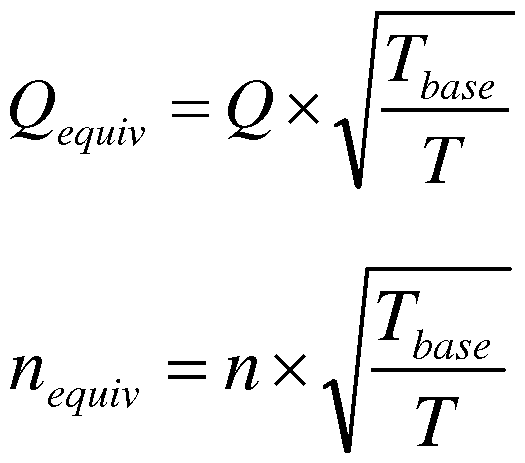
Q(T,n) = Qeqmv + clxn

如果用二次多项式:

如果用线性关系式,
 如果用二次多项式 base
+ clxn + c2xn x
base TxV
这个调整系数 V值在 0.1到 2之间变化, 选取的原则是让从上式计算出来 的风量值与实际测试值相等或相近, 如表 1是某负载的 V值表, 表 1中基准力 矩 Tbase设为 50% T。, 其它力矩为测试方便选为: 10%Τ。、 20%Τ。、 30%Τ。、 40%Τ。、 60%Τ。、 70%Τ。、 80%Τ。、 90%Τ。、 100%Τ。, 对应的调整系数 V值也记录在表 1中, 其中 Τ。为电机额定力矩, 在其他未测量的力矩工况下, V值可由邻近的两个 Τ 所属的 V值来线性插值计算获得。

表 1某负载的 V值表
上述的计算式是以选定一个基准力矩 为前提,从而推导出一个该力矩 下的风量与转速的函数关系式。 从保证计算精度, 并简化计算量的角度来看, 这个函数既可以是线性的,
0 ^equi .v =cO + clx7i equiv
也可以是二次多项式 ft -equiv = cO + clx7i equi .v +c2x7i e2qui .v
实验数据表明, 如果用更高阶的函数来描述风量与转速的关系会产生 "过 度曲线拟合" 的问题, 即计算量远远增大而拟合精度并未提高的现象。 有了这 个函数, 可以进一步推导在其他任意力矩和转速下, 风量的计算函数 Q=F (T, n, V)。 在不同的力矩下, 调整系数 V值也不同。 因此, 需要设置好电机在恒 力矩工作状态, 在不大于额定力矩的范围内, 选择包括基准力矩在内的多个力
矩 τ的值, 使电机在每个力矩 τ下工作, 并依次改变系统的外部静压, 来釆集 包括转速, 风量参数的原始数据测量。 某负载的部分原始数据的测试结果如下 表 2所示, 通过原始数据得到表 1所示的不同力矩下对应的调整系数 V,其选 取的原则是让从上式计算出来的风量值与实际测试值相等或相近。
实测转速
力矩 τ 静压(Pa) 实测风量 Q (CFM)
( RPM )
TO* 100% 25 1476.5 314
TO* 100% 50 1441.1 935
TO* 100% 75 1407.7 968
实测转速
力矩 τ 静压(Pa) 实测风量 Q (CFM)
( RPM )
Τ0*50% 25 1072.3 713
Τ0*50% 50 1035.8 750
Τ0*50% 75 785 实测转速
力矩 τ 静压(Pa) 实测风量 Q (CFM)
( RPM )
TO* 10% 25 573.0 472
TO* 10% 37.5 503.8 501
TO* 10% 50 486.6 545
表 2 某负载的部分原始数据
下面举例说明恒风量的控制过程:
步骤 1 )获取以上表为例的原始数据后, 选定基准力矩 T = 50%To, 利用转 速 η和实测风量 Q的数据进行绘图拟合成直线,建立计算风量在基准力矩下的 的函数关系 Qbase=F (n) , 这里以基准力矩下的线性关系式为例:
0 ^equi .v =c0 + clx7i equiv 绘制成图像如图 4所示。 于是可以按照曲线拟合的方法获得两个风量系数 c。, Cl。 然后在原始数据的基础上, 按照 "选择 V值使计算风量的结果与实测风量 的结果相等或相近" 为原则确定所有力矩下的 V值, 如表 1所示。 这时, 任意 转速与力矩下的风量函数关系式 Q=F (Τ, n, V)可以确定如下:
TxV
Q = cO + clxn
base 其中 Q是风量 (CFM), T是力矩(0Z-ft), n是转速 (RPM), V是调整系数如表 1 所示, 并预先输入到电机控制器的微处理器里面;
步骤 2 ) 空调系统控制器向电机控制器的微处理器输入目标风量 Q„f;
步骤 3至步骤 8的见图 5所示,
步骤 3)在一定的力矩 T下启动电机, 使电机进入稳态;
步骤 4 )记录这时候的稳态转速 n, 电机控制器通过查表法查找对应的调整 系数 V, 并计算出计算风量 (k 步骤 5 ) 比较目标风量 Q„f与计算风量 Q。, 若目标风量 Q„f与计算风量 Q。相 等或相当, 则电机维持当前力矩进入稳态工作并记录该稳态下的转速 n; 若目 标风量 Qref大于计算风量 Qc, 电机控制器提升输出力矩 T, 若目标风量 Qref少于
计算风量 Q。, 电机控制器的微处理器减少输出力矩 T;
步骤 6 ) 电机经调整力矩进入稳态后, 重新记录提升或者减少力矩下的稳 态转速 η, 电机控制器通过查表法重新查找对应的调整系数 V, 重新计算新稳 态下的风量 Qc;
步骤 7)重复步骤 5和步骤 6 , 直到计算风量 Q。与目标风量 Qref相等或相当, 停止调整力矩电机进入稳态, 同时记录该稳态下的转速 n。
上述所述的步骤 7)后面还有步骤 8 ), 如果外部系统发生改变 (比如通风 管道积灰或部分堵塞), 导致转速和输出风量变化, 这时电机控制器通过比较 新的稳态转速和步骤 5 )或步骤 7 ) 里的转速可以知道输出风量已经发生了变 化。 重复步骤 4、 步骤 5、 步骤 6和步骤 7。
Claims
1、 一种电机的恒风量控制方法, 其特征在于, 它包括如下步骤过程:
步骤 1 )先通过实验, 在恒力矩模式下测试某个风机系统在多个力矩下, 风量与转速的关系, 从而建立任意力矩和转速下计算风量的函数关系 Q=F ( T, n, V),其中 Q是风量, T是力矩, !!是转速, V是调整系数, 多个力矩段都有 一个对应的调整系数 V, 并输入到电机控制器的微处理器里面;
步骤 2 ) 电机控制器的微处理器接受外部输入的目标风量 Qref。
步骤 3 )电机控制器控制电机在一定的力矩 T下启动电机, 使电机进入稳 态;
步骤 4 ) 记录这时候的稳态转速 n, 并通过查表法获得该力矩 T下的调整 系数 V, 然后根据步骤 1里的方程计算出该稳态下的风量 Q。;
步骤 5 ) 电机控制器的微处理器比较目标风量 Qref与计算风量 Q。, 若目标 风量 Q f与计算风量 Q。相等或相当, 则电机维持当前力矩进入稳态工作并记录 该稳态下的转速 n; 若目标风量 Qref大于计算风量 Q。, 电机控制器提升输出力 矩 T, 若目标风量 Qref少于计算风量 Q。, 电机控制器的微处理器减少输出力矩 T;
步骤 6 ) 电机经调整力矩进入稳态后, 重新记录提升或者减少力矩下的稳 态转速 n, 并再次查表获取新力矩下的 V值, 然后重新计算风量 Q。;
步骤 7)重复步骤 5和步骤 6 , 直到计算风量 Q。与目标风量 Qref相等或相当, 停止调整力矩,电机进入稳态, 同时记录该稳态下的转速 n。
2、 根据权利要求 1所述的一种电机的恒风量控制方法, 其特征在于:步骤 7)后面还有步骤 8 ), 如果外部系统发生改变, 导致转速和输出风量变化, 这 时电机控制器通过比较新的稳态转速和步骤 5 )或步骤 7 ) 里的转速可以知道
输出风量已经发生了变化, 重复步骤 4、 步骤 5、 步骤 6和步骤 7。
3、 根据权利要求 1 所述的一种电机的恒风量控制方法, 其特征在于

或者釆用

系数 c。, c^P c2是通过在基准力矩 Tbase, 不同外部静压情况下根据转速和风量 参数的原始数据通过曲线拟合的方法来获得。
4、 根据权利要求 3所述的一种电机的恒风量控制方法, 其特征在于: 基准 力矩 Tbase的范围为 30%T。至讀。, Τ。是电机额定力矩。
5、 根据权利要求 1、 2或 3所述的一种电机的恒风量控制方法, 其特征在 于: 函数关系 Q=F ( T, n, V)中调整系数 V值在 0. 1到 2之间变化。
6、 根据权利要求 1、 2或 3所述的一种电机的恒风量控制方法, 其特征在 于: 步骤 5和步骤 7)所述的计算风量 Q。与目标风量 Q„f相等或相当, 指计算风 量 Qc在目标风量 Qref ±误差窗口之内, 目标风量 Q„f的误差窗口一般在 1%到 2% 范围内。
7、 根据权利要求 1、 2或 3所述的一种电机的恒风量控制方法, 其特征在 于: 步骤 5)所述的电机控制器提升或减少输出力矩 T, 主要指在步骤 5)所述 力矩 T下按每次至少 1%T。的步长顺序提升或减少, 或者可以让新力矩 =当前力 矩) ((目标风量 Q„f/当前计算风量 Qc)2。
8、 根据权利要求 1、 2或 3所述的一种电机的恒风量控制方法, 其特征在 于: 函数关系 Q=F ( T , n, V)是利用基准力矩和其他力矩下的不同外部静压情
况下转速和风量参数的原始数据来获得的,将电机安装在风轮上放在一个空调 设备里面, 设置好电机在恒力矩工作状态, 在不大于额定力矩的范围内, 选择 包括基准力矩在内的多个力矩的值,使电机在每个力矩下工作, 并依次改变系 统的外部静压, 来釆集包括转速, 风量参数的原始数据。
9、 一种空调风机系统的恒风量控制方法, 所述的空调风机系统包括电机 和风轮, 所述的电机包括电机控制器、 定子组件和转子组件, 其特征在于: 它 包括如下步骤过程:
步骤 1 )设置好电机在恒力矩工作状态, 在不大于额定力矩的范围内, 选 择包括基准力矩在内的多个力矩的值,使电机在每个力矩工作, 并依次改变系 统的外部静压, 来釆集包括转速, 风量参数的原始数据;
步骤 2 )在电机控制器的微处理器里面建立计算风量的函数关系 Q=F ( T, n, V),其中 Q是风量, T是力矩, !!是转速, V是调整系数, 多个力矩段都有 一个对应的调整系数 V, 并输入到电机控制器的微处理器里面;
步骤 3 ) 电机控制器接受外部输入的目标风量 Qref ;
步骤 4 )在一定的力矩 T下启动电机, 使电机进入稳态;
步骤 5 )记录这时候的稳态转速 n, 并通过查表法获得该力矩 T下的调整系 数 V , 然后根据步骤 1里的方程计算出该稳态下的风量 Q。;
步骤 6 ) 比较目标风量 Qr ef与计算风量 Q。, 若目标风量 Qref与计算风量 Qc相 等或相当, 则电机维持当前力矩进入稳态工作并记录该稳态下的转速 n; 若目 标风量 Qr ef大于计算风量 Qc , 电机控制器提升输出力矩 T, 若目标风量 Qref少于 计算风量 Q。, 电机控制器的微处理器减少输出力矩 T;
步骤 7 ) 电机经调整力矩进入稳态后, 重新记录提升或者减少力矩下的稳 态转速 n, 电机控制器通过查表法重新查找对应的调整系数 V, 重新计算新稳
态下的风量 Qc ;
步骤 8)重复步骤 6和步骤 7 , 直到计算风量 Q。与目标风量 Qr ef相等或相当, 停止调整力矩, 电机进入稳态, 同时记录该稳态下的转速 n。
10、 根据权利要求 9所述的一种空调风机系统的恒风量控制方法, 其特征 在于: 步骤 8)后面还有步骤 9 ), 如果外部系统发生改变, 导致转速和输出风 量变化, 这时电机控制器通过比较新的稳态转速和步骤 6 )或步骤 8 ) 里的转 速可以知道输出风量已经发生了变化。 重复步骤 5、 步骤 6、 步骤 7和步骤 8。
11、 根据权利要求 9所述的一种空调风机系统的恒风量控制方法, 其特征 在于:

或者釆用

系数 c。, c^P c2是通过在基准力矩 Tbase, 不同外部静压情况下根据转速和风量 参数的原始数据通过曲线拟合的方法来获得。
12、 根据权利要求 11所述的一种空调风机系统的恒风量控制方法, 其特 征在于: 基准力矩 Tbase的范围为 30%T。至 80%T。, Τ。是电机额定力矩。
1 3、 根据权利要求 9、 10或 11所述的一种电机的恒风量控制方法, 其特 征在于: 函数关系 Q=F ( T, n, V)中调整系数 V值在 0. 1到 2之间变化。
14、 根据权利要求 9、 10或 11所述的一种电机的恒风量控制方法, 其特 征在于: 步骤 6和步骤 8)所述的计算风量 Q。与目标风量 Qref相等或相当, 指计 算风量 Qc在目标风量 Qref士误差窗口之内, 目标风量 Qr ef的误差窗口一般在 1%
到 2%范围内。
15、 根据权利要求 9、 10或 11所述的一种电机的恒风量控制方法, 其特 征在于: 步骤 6)所述的电机控制器提升或减少输出力矩 T, 主要指在步骤 6) 所述力矩 T下按每次至少 1%T。的步长顺序提升或减少, 或者可以让新力矩 =当 前力矩 X (目标风量 Qref/当前计算风量 Q。)2。
Applications Claiming Priority (4)
| Application Number | Priority Date | Filing Date | Title |
|---|---|---|---|
| CN201210127208.0 | 2012-04-26 | ||
| CN201210127123.2 | 2012-04-26 | ||
| CN201210127208.0A CN103375419B (zh) | 2012-04-26 | 2012-04-26 | 一种电机及空调风机系统的恒风量控制方法 |
| CN201210127123.2A CN103376743B (zh) | 2012-04-26 | 2012-04-26 | 一种电机及空调风机系统的恒风量控制方法 |
Publications (1)
| Publication Number | Publication Date |
|---|---|
| WO2013159458A1 true WO2013159458A1 (zh) | 2013-10-31 |
Family
ID=49482190
Family Applications (2)
| Application Number | Title | Priority Date | Filing Date |
|---|---|---|---|
| PCT/CN2012/078545 Ceased WO2013159458A1 (zh) | 2012-04-26 | 2012-07-12 | 一种电机及空调风机系统的恒风量控制方法 |
| PCT/CN2012/078749 Ceased WO2013159461A1 (zh) | 2012-04-26 | 2012-07-17 | 一种电机及空调风机系统的恒风量控制方法 |
Family Applications After (1)
| Application Number | Title | Priority Date | Filing Date |
|---|---|---|---|
| PCT/CN2012/078749 Ceased WO2013159461A1 (zh) | 2012-04-26 | 2012-07-17 | 一种电机及空调风机系统的恒风量控制方法 |
Country Status (1)
| Country | Link |
|---|---|
| WO (2) | WO2013159458A1 (zh) |
Cited By (4)
| Publication number | Priority date | Publication date | Assignee | Title |
|---|---|---|---|---|
| CN105864973A (zh) * | 2016-04-14 | 2016-08-17 | 常州绿谷物联网科技有限公司 | 新风净化系统风阻识别方法及其装置 |
| CN109945452A (zh) * | 2019-03-25 | 2019-06-28 | 珠海格力电器股份有限公司 | 恒定风量的风机及其控制方法、空调 |
| EP3702686A1 (en) * | 2019-03-01 | 2020-09-02 | Belimo Holding AG | A method of monitoring an air flow in a zone of an hvac system |
| CN111829145A (zh) * | 2020-06-09 | 2020-10-27 | 华帝股份有限公司 | 一种厨房空调的控制方法 |
Citations (8)
| Publication number | Priority date | Publication date | Assignee | Title |
|---|---|---|---|---|
| US4806833A (en) * | 1986-09-22 | 1989-02-21 | General Electric Company | System for conditioning air, method of operating such, and circuit |
| CN1854625A (zh) * | 2005-04-18 | 2006-11-01 | 上海大智科技发展有限公司 | 一种变风量空调系统定静压与总风量双重控制方法 |
| CN201242243Y (zh) * | 2008-06-30 | 2009-05-20 | 湖南大学 | 一种实现变风量空调系统送风静压优化控制方法的装置 |
| CN101440988A (zh) * | 2008-12-29 | 2009-05-27 | 贵州汇通华城楼宇科技有限公司 | 中央空调均衡送风动态调节方法及装置 |
| US20090134823A1 (en) * | 2007-11-28 | 2009-05-28 | Young-Chun Jeung | Multi-level programming of motor for a ventilation system |
| US20100133817A1 (en) * | 2009-07-07 | 2010-06-03 | General Electric Company | Method and apparatus for controlling the tip speed of a blade of a wind turbine |
| US20100298993A1 (en) * | 2009-05-21 | 2010-11-25 | Lennox Industries, Incorporated | Airflow managing system, a method of monitoring the airflow in an hvac system and a hvac system |
| US20110053488A1 (en) * | 2008-01-18 | 2011-03-03 | Mpc Inc. | Control system for exhaust gas fan system |
Family Cites Families (2)
| Publication number | Priority date | Publication date | Assignee | Title |
|---|---|---|---|---|
| WO2008117515A1 (ja) * | 2007-03-27 | 2008-10-02 | Panasonic Corporation | モータ制御装置とその制御方法、及びモータ装置 |
| CN201531444U (zh) * | 2009-09-16 | 2010-07-21 | 中山大洋电机股份有限公司 | 一种空调风机控制系统 |
-
2012
- 2012-07-12 WO PCT/CN2012/078545 patent/WO2013159458A1/zh not_active Ceased
- 2012-07-17 WO PCT/CN2012/078749 patent/WO2013159461A1/zh not_active Ceased
Patent Citations (8)
| Publication number | Priority date | Publication date | Assignee | Title |
|---|---|---|---|---|
| US4806833A (en) * | 1986-09-22 | 1989-02-21 | General Electric Company | System for conditioning air, method of operating such, and circuit |
| CN1854625A (zh) * | 2005-04-18 | 2006-11-01 | 上海大智科技发展有限公司 | 一种变风量空调系统定静压与总风量双重控制方法 |
| US20090134823A1 (en) * | 2007-11-28 | 2009-05-28 | Young-Chun Jeung | Multi-level programming of motor for a ventilation system |
| US20110053488A1 (en) * | 2008-01-18 | 2011-03-03 | Mpc Inc. | Control system for exhaust gas fan system |
| CN201242243Y (zh) * | 2008-06-30 | 2009-05-20 | 湖南大学 | 一种实现变风量空调系统送风静压优化控制方法的装置 |
| CN101440988A (zh) * | 2008-12-29 | 2009-05-27 | 贵州汇通华城楼宇科技有限公司 | 中央空调均衡送风动态调节方法及装置 |
| US20100298993A1 (en) * | 2009-05-21 | 2010-11-25 | Lennox Industries, Incorporated | Airflow managing system, a method of monitoring the airflow in an hvac system and a hvac system |
| US20100133817A1 (en) * | 2009-07-07 | 2010-06-03 | General Electric Company | Method and apparatus for controlling the tip speed of a blade of a wind turbine |
Cited By (7)
| Publication number | Priority date | Publication date | Assignee | Title |
|---|---|---|---|---|
| CN105864973A (zh) * | 2016-04-14 | 2016-08-17 | 常州绿谷物联网科技有限公司 | 新风净化系统风阻识别方法及其装置 |
| EP3702686A1 (en) * | 2019-03-01 | 2020-09-02 | Belimo Holding AG | A method of monitoring an air flow in a zone of an hvac system |
| CN111637953A (zh) * | 2019-03-01 | 2020-09-08 | 贝利莫控股公司 | 监测hvac系统的区域中的空气流量的方法 |
| CN111637953B (zh) * | 2019-03-01 | 2022-04-15 | 贝利莫控股公司 | 监测hvac系统的区域中的空气流量的方法 |
| US11448410B2 (en) | 2019-03-01 | 2022-09-20 | Belimo Holding Ag | Method of monitoring an air flow in a zone of an HVAC system |
| CN109945452A (zh) * | 2019-03-25 | 2019-06-28 | 珠海格力电器股份有限公司 | 恒定风量的风机及其控制方法、空调 |
| CN111829145A (zh) * | 2020-06-09 | 2020-10-27 | 华帝股份有限公司 | 一种厨房空调的控制方法 |
Also Published As
| Publication number | Publication date |
|---|---|
| WO2013159461A1 (zh) | 2013-10-31 |
Similar Documents
| Publication | Publication Date | Title |
|---|---|---|
| CN103376743B (zh) | 一种电机及空调风机系统的恒风量控制方法 | |
| CN103375419B (zh) | 一种电机及空调风机系统的恒风量控制方法 | |
| US9347453B2 (en) | Method for controlling air volume | |
| US10066631B2 (en) | Direct power control for constant airflow control | |
| US9732976B2 (en) | Direct power control for constant airflow control with advanced motor system modeling | |
| US8880224B2 (en) | Airflow managing system, a method of monitoring the airflow in an HVAC system and a HVAC system | |
| US8672733B2 (en) | Ventilation airflow rate control | |
| US8738185B2 (en) | Altitude adjustment for heating, ventilating and air conditioning systems | |
| WO2016065874A1 (zh) | 一种具有抽风或者送风功能的电器设备的恒风量控制方法 | |
| CN110630554A (zh) | 风机无级恒风量控制方法、风机控制装置及风机 | |
| CN106288135A (zh) | 空调的风机转速的调整方法 | |
| JP5988224B2 (ja) | モータ制御装置及びモータ制御方法 | |
| WO2013159458A1 (zh) | 一种电机及空调风机系统的恒风量控制方法 | |
| US10855211B2 (en) | Self-calibration of ECM motor and variable frequency drive inferred torque | |
| JP2012042406A (ja) | 圧力検出装置及び圧力検出方法 |
Legal Events
| Date | Code | Title | Description |
|---|---|---|---|
| 121 | Ep: the epo has been informed by wipo that ep was designated in this application |
Ref document number: 12875586 Country of ref document: EP Kind code of ref document: A1 |
|
| NENP | Non-entry into the national phase |
Ref country code: DE |
|
| 122 | Ep: pct application non-entry in european phase |
Ref document number: 12875586 Country of ref document: EP Kind code of ref document: A1 |