WO2013157531A1 - Threaded reinforcing bar coupling for deformed reinforcing bar, and threaded deformed reinforcing bar - Google Patents
Threaded reinforcing bar coupling for deformed reinforcing bar, and threaded deformed reinforcing bar Download PDFInfo
- Publication number
- WO2013157531A1 WO2013157531A1 PCT/JP2013/061235 JP2013061235W WO2013157531A1 WO 2013157531 A1 WO2013157531 A1 WO 2013157531A1 JP 2013061235 W JP2013061235 W JP 2013061235W WO 2013157531 A1 WO2013157531 A1 WO 2013157531A1
- Authority
- WO
- WIPO (PCT)
- Prior art keywords
- reinforcing bar
- diameter
- threaded
- enlarged
- deformed
- Prior art date
Links
- 230000003014 reinforcing effect Effects 0.000 title claims abstract description 440
- 230000008878 coupling Effects 0.000 title abstract description 3
- 238000010168 coupling process Methods 0.000 title abstract description 3
- 238000005859 coupling reaction Methods 0.000 title abstract description 3
- 239000000463 material Substances 0.000 claims abstract description 54
- 230000002093 peripheral effect Effects 0.000 claims abstract description 33
- 238000004519 manufacturing process Methods 0.000 claims description 44
- 238000005096 rolling process Methods 0.000 claims description 33
- 238000000034 method Methods 0.000 claims description 28
- 239000004567 concrete Substances 0.000 claims description 21
- XEEYBQQBJWHFJM-UHFFFAOYSA-N Iron Chemical compound [Fe] XEEYBQQBJWHFJM-UHFFFAOYSA-N 0.000 claims description 18
- 238000005520 cutting process Methods 0.000 claims description 18
- 230000015572 biosynthetic process Effects 0.000 claims description 12
- 229910052742 iron Inorganic materials 0.000 claims description 9
- 239000002994 raw material Substances 0.000 claims 2
- 229910000831 Steel Inorganic materials 0.000 abstract description 5
- 239000010959 steel Substances 0.000 abstract description 5
- 230000008569 process Effects 0.000 description 9
- 230000000694 effects Effects 0.000 description 7
- 230000002787 reinforcement Effects 0.000 description 7
- 230000007547 defect Effects 0.000 description 6
- 238000003466 welding Methods 0.000 description 5
- 229910001294 Reinforcing steel Inorganic materials 0.000 description 4
- 239000004744 fabric Substances 0.000 description 4
- 239000011150 reinforced concrete Substances 0.000 description 4
- 238000007906 compression Methods 0.000 description 3
- 238000010276 construction Methods 0.000 description 3
- 239000011440 grout Substances 0.000 description 3
- 238000010438 heat treatment Methods 0.000 description 3
- 230000008901 benefit Effects 0.000 description 2
- 230000006835 compression Effects 0.000 description 2
- 230000006872 improvement Effects 0.000 description 2
- 238000005304 joining Methods 0.000 description 2
- 230000004048 modification Effects 0.000 description 2
- 238000012986 modification Methods 0.000 description 2
- 238000005452 bending Methods 0.000 description 1
- 230000008859 change Effects 0.000 description 1
- 238000006243 chemical reaction Methods 0.000 description 1
- 230000006866 deterioration Effects 0.000 description 1
- 230000006698 induction Effects 0.000 description 1
- 238000011031 large-scale manufacturing process Methods 0.000 description 1
- 238000000465 moulding Methods 0.000 description 1
- 238000007781 pre-processing Methods 0.000 description 1
- 238000000926 separation method Methods 0.000 description 1
- 238000007493 shaping process Methods 0.000 description 1
- 238000009751 slip forming Methods 0.000 description 1
Images


Classifications
-
- B—PERFORMING OPERATIONS; TRANSPORTING
- B21—MECHANICAL METAL-WORKING WITHOUT ESSENTIALLY REMOVING MATERIAL; PUNCHING METAL
- B21H—MAKING PARTICULAR METAL OBJECTS BY ROLLING, e.g. SCREWS, WHEELS, RINGS, BARRELS, BALLS
- B21H3/00—Making helical bodies or bodies having parts of helical shape
- B21H3/02—Making helical bodies or bodies having parts of helical shape external screw-threads ; Making dies for thread rolling
- B21H3/04—Making by means of profiled-rolls or die rolls
-
- F—MECHANICAL ENGINEERING; LIGHTING; HEATING; WEAPONS; BLASTING
- F16—ENGINEERING ELEMENTS AND UNITS; GENERAL MEASURES FOR PRODUCING AND MAINTAINING EFFECTIVE FUNCTIONING OF MACHINES OR INSTALLATIONS; THERMAL INSULATION IN GENERAL
- F16B—DEVICES FOR FASTENING OR SECURING CONSTRUCTIONAL ELEMENTS OR MACHINE PARTS TOGETHER, e.g. NAILS, BOLTS, CIRCLIPS, CLAMPS, CLIPS OR WEDGES; JOINTS OR JOINTING
- F16B7/00—Connections of rods or tubes, e.g. of non-circular section, mutually, including resilient connections
- F16B7/18—Connections of rods or tubes, e.g. of non-circular section, mutually, including resilient connections using screw-thread elements
- F16B7/185—Connections of rods or tubes, e.g. of non-circular section, mutually, including resilient connections using screw-thread elements with a node element
-
- B—PERFORMING OPERATIONS; TRANSPORTING
- B21—MECHANICAL METAL-WORKING WITHOUT ESSENTIALLY REMOVING MATERIAL; PUNCHING METAL
- B21B—ROLLING OF METAL
- B21B1/00—Metal-rolling methods or mills for making semi-finished products of solid or profiled cross-section; Sequence of operations in milling trains; Layout of rolling-mill plant, e.g. grouping of stands; Succession of passes or of sectional pass alternations
- B21B1/16—Metal-rolling methods or mills for making semi-finished products of solid or profiled cross-section; Sequence of operations in milling trains; Layout of rolling-mill plant, e.g. grouping of stands; Succession of passes or of sectional pass alternations for rolling wire rods, bars, merchant bars, rounds wire or material of like small cross-section
-
- B—PERFORMING OPERATIONS; TRANSPORTING
- B21—MECHANICAL METAL-WORKING WITHOUT ESSENTIALLY REMOVING MATERIAL; PUNCHING METAL
- B21H—MAKING PARTICULAR METAL OBJECTS BY ROLLING, e.g. SCREWS, WHEELS, RINGS, BARRELS, BALLS
- B21H3/00—Making helical bodies or bodies having parts of helical shape
- B21H3/02—Making helical bodies or bodies having parts of helical shape external screw-threads ; Making dies for thread rolling
-
- E—FIXED CONSTRUCTIONS
- E04—BUILDING
- E04C—STRUCTURAL ELEMENTS; BUILDING MATERIALS
- E04C5/00—Reinforcing elements, e.g. for concrete; Auxiliary elements therefor
- E04C5/16—Auxiliary parts for reinforcements, e.g. connectors, spacers, stirrups
- E04C5/162—Connectors or means for connecting parts for reinforcements
- E04C5/163—Connectors or means for connecting parts for reinforcements the reinforcements running in one single direction
- E04C5/165—Coaxial connection by means of sleeves
-
- F—MECHANICAL ENGINEERING; LIGHTING; HEATING; WEAPONS; BLASTING
- F16—ENGINEERING ELEMENTS AND UNITS; GENERAL MEASURES FOR PRODUCING AND MAINTAINING EFFECTIVE FUNCTIONING OF MACHINES OR INSTALLATIONS; THERMAL INSULATION IN GENERAL
- F16B—DEVICES FOR FASTENING OR SECURING CONSTRUCTIONAL ELEMENTS OR MACHINE PARTS TOGETHER, e.g. NAILS, BOLTS, CIRCLIPS, CLAMPS, CLIPS OR WEDGES; JOINTS OR JOINTING
- F16B5/00—Joining sheets or plates, e.g. panels, to one another or to strips or bars parallel to them
- F16B5/02—Joining sheets or plates, e.g. panels, to one another or to strips or bars parallel to them by means of fastening members using screw-thread
- F16B5/0275—Joining sheets or plates, e.g. panels, to one another or to strips or bars parallel to them by means of fastening members using screw-thread the screw-threaded element having at least two axially separated threaded portions
-
- F—MECHANICAL ENGINEERING; LIGHTING; HEATING; WEAPONS; BLASTING
- F16—ENGINEERING ELEMENTS AND UNITS; GENERAL MEASURES FOR PRODUCING AND MAINTAINING EFFECTIVE FUNCTIONING OF MACHINES OR INSTALLATIONS; THERMAL INSULATION IN GENERAL
- F16B—DEVICES FOR FASTENING OR SECURING CONSTRUCTIONAL ELEMENTS OR MACHINE PARTS TOGETHER, e.g. NAILS, BOLTS, CIRCLIPS, CLAMPS, CLIPS OR WEDGES; JOINTS OR JOINTING
- F16B7/00—Connections of rods or tubes, e.g. of non-circular section, mutually, including resilient connections
- F16B7/18—Connections of rods or tubes, e.g. of non-circular section, mutually, including resilient connections using screw-thread elements
- F16B7/182—Connections of rods or tubes, e.g. of non-circular section, mutually, including resilient connections using screw-thread elements for coaxial connections of two rods or tubes
-
- B—PERFORMING OPERATIONS; TRANSPORTING
- B21—MECHANICAL METAL-WORKING WITHOUT ESSENTIALLY REMOVING MATERIAL; PUNCHING METAL
- B21B—ROLLING OF METAL
- B21B1/00—Metal-rolling methods or mills for making semi-finished products of solid or profiled cross-section; Sequence of operations in milling trains; Layout of rolling-mill plant, e.g. grouping of stands; Succession of passes or of sectional pass alternations
- B21B1/16—Metal-rolling methods or mills for making semi-finished products of solid or profiled cross-section; Sequence of operations in milling trains; Layout of rolling-mill plant, e.g. grouping of stands; Succession of passes or of sectional pass alternations for rolling wire rods, bars, merchant bars, rounds wire or material of like small cross-section
- B21B1/163—Rolling or cold-forming of concrete reinforcement bars or wire ; Rolls therefor
-
- F—MECHANICAL ENGINEERING; LIGHTING; HEATING; WEAPONS; BLASTING
- F16—ENGINEERING ELEMENTS AND UNITS; GENERAL MEASURES FOR PRODUCING AND MAINTAINING EFFECTIVE FUNCTIONING OF MACHINES OR INSTALLATIONS; THERMAL INSULATION IN GENERAL
- F16B—DEVICES FOR FASTENING OR SECURING CONSTRUCTIONAL ELEMENTS OR MACHINE PARTS TOGETHER, e.g. NAILS, BOLTS, CIRCLIPS, CLAMPS, CLIPS OR WEDGES; JOINTS OR JOINTING
- F16B33/00—Features common to bolt and nut
- F16B33/02—Shape of thread; Special thread-forms
Definitions
- the present invention relates to a deformed reinforcing bar screw-type reinforcing bar joint used for reinforced concrete, and a threaded deformed reinforcing bar.
- deformed reinforcing bars are generally used as reinforcing bars.
- various reinforcing bar joints are used in order to make a limited length of reinforcing bars continuous in the field.
- As the reinforcing bar joint a lap joint or a gas pressure welding joint in which the reinforcing bars are stacked by a predetermined length is generally used.
- the lap joint has a complicated bar arrangement structure due to the overlap, and the gas pressure joint has a drawback that the quality of the joint depends on the skill of the pressure welding. Therefore, as a special joint, a joint has been developed in which grout is injected into the sleeve together with the reinforcing bar. This special joint for injecting grout is preferable in view of simplification of the bar arrangement structure, and has been put to practical use.
- For curing the grout for example, a curing period of about one day is required and the construction period is long. is there.
- Threaded joints have been proposed as special joints that require a short construction period (Patent Document 1).
- Patent Document 1 in order to ensure the connection strength, a diameter-enlarged portion is provided at the end of the reinforcing bar, screwing is performed, or a separate large-diameter screw shaft is joined to the reinforcing bar end by friction welding. It is described.
- Threaded rebar joints are excellent in that they can be constructed in a short time as described above, but it is necessary to expand the diameter of the male thread at the end in order to ensure connection strength.
- As a method of this diameter expansion process there are a method in which a separate large-diameter screw shaft is joined to the end of the reinforcing bar by friction welding and a method in which the reinforcing bar is heated to increase the diameter by applying a compressive force.
- these friction welding and heat compression processes require large-scale equipment to ensure accuracy and reliability, and it is difficult to ensure productivity.
- An object of the present invention is to provide a deformed rebar threaded rebar joint in which a male threaded portion at the end of the rebar is easy to form, excellent in productivity, and excellent in the strength of the male threaded portion, and the thread of the deformed rebar It is intended to simplify the manufacture of threaded deformed reinforcing bars used in the type rebar joint and improve productivity.
- the threaded reinforcing bar joint of the deformed reinforcing bar of the present invention is a reinforcing bar joint for connecting a pair of reinforcing bars, and has a male threaded portion at the opposite end of the pair of reinforcing bars connected to each other, and extends over the male threaded portion of both reinforcing bars.
- the outer diameter of the enlarged diameter portion is formed to be equal to or less than the outermost diameter of the reinforcing bar including the protrusion of the reinforcing bar, and the male screw portion is formed by rolling the enlarged diameter portion.
- the end of the reinforcing bar is a male threaded part that has been threaded as a diameter-enlarged part. Is secured.
- the male threaded part is processed into a diameter-enlarged part of the rebar, but the diameter-enlarged part is less than the outermost diameter of the reinforcing bar, which is the outer diameter of the reinforcing bar including the deformed reinforcing bar protrusions. It can be manufactured as a reinforcing bar.
- the reinforcing bar will not bend in contact with the guide during the manufacture of the reinforcing bar. It can be manufactured as a reinforcing bar. Therefore, it is not necessary to provide a diameter expansion processing facility separately from the reinforcing bar manufacturing facility, the facility can be simplified, and the productivity is excellent.
- the male thread portion of the reinforcing bar is a rolled screw, unlike the case of cutting the thread groove, there is no material removal, the cross-sectional area is offset between the thread groove and the thread, and the diameter-enlarged portion is The effect of reinforcement by expanding the diameter can be enhanced as much as possible within a limited range of the outermost diameter of the reinforcing bar.
- one of the reinforcing bars is not limited to the reinforcing bar in which the male threaded portion is formed in the above-mentioned enlarged diameter portion, and may be any reinforcing bar having a male screw.
- the reinforcing bar on the large-diameter side may be a reinforcing bar in which an end part is processed into a perfect circle and a male thread part is formed in the processed part in a perfect circle.
- both ends of the thick reinforcing bar may be threaded and used as a reinforcing bar.
- At least one of the deformed reinforcing bars is a helical relief that fits a portion of the outer thread on the outer surface of the threaded part of the threaded portion of the threaded cylinder. It is good also as an escape thread part in which the groove
- the length of the escape screw portion is preferably equal to or longer than the length of the screw cylinder minus the length of the male screw portion.
- the helical relief groove does not need to have a shape that contributes to screw connection, and may have any cross-sectional shape that can release the screw thread of the screw cylinder, and has a cross-sectional shape that causes a large gap in the meshing portion. Also good. It is preferable that the part of the deformed reinforcing bar as the escape screw part has a larger outer diameter of the reinforcing bar body than the general part of the deformed reinforcing bar.
- the screw tube protrudes from one of the reinforcing bars without causing a problem of interference with the deformed reinforcing bar protrusion when connecting with the screw tube. It is possible to screw over the reinforcing bars on both sides by screwing in the far side to the position where it does not, screwing the other reinforcing bar to the end of the one reinforcing bar and then screwing it back. According to such a connection method, when the screw cylinder is rotated and joined, it is not necessary to move the rebar greatly with screwing.
- the rib which is a protrusion extended along a length direction among the protrusions of a deformed reinforcing bar contributes to the cross-sectional area of a reinforcing bar, and when the said helical relief groove
- a cross-sectional defect is generated accordingly, and there is a possibility that the portion becomes insufficient in strength when a tensile force is applied.
- the reinforcing bar material corresponding to the cross-sectional defect generated in the rib by the threading process plastically flows to the circumferential portion different from the rib at the same length direction position.
- the cross-sectional area of the entire rebar is constant regardless of the processing of the spiral relief groove. Therefore, the problem that the strength is reduced due to the formation of the spiral relief groove is avoided.
- the outer diameter of the reinforcing bar main body is preferably larger than the general part of the deformed reinforcing bar.
- the cross-sectional area corresponding to the rib cross-sectional area may be covered by shallowing the valleys.
- the threaded deformed reinforcing bar of the present invention is a deformed reinforcing bar connected by the threaded reinforcing bar joint of the present invention, has a protrusion on the outer peripheral surface of the reinforcing bar main body, has a male threaded portion at the end, and Forming the protrusion on the outer peripheral surface by roll forming of iron wire material, and forming an enlarged diameter part in a part of the length direction, the outer diameter of the enlarged diameter part is the protrusion of the reinforcing bar And the male threaded portion is formed by rolling in the enlarged diameter portion.
- the diameter-expanding part is equal to or less than the outermost outer diameter of the reinforcing bar including the ridge
- the diameter-expanding part at the time of manufacturing the deformed reinforcing bar It can be manufactured as a reinforcing steel bar. Therefore, it is not necessary to provide a diameter expansion processing facility separately from the reinforcing bar manufacturing facility, the facility can be simplified, and the productivity is excellent.
- the cross-sectional area is offset between the thread groove and the thread, and the diameter-enlarged part is less than the outermost diameter of the reinforcing bar.
- the threaded deformed reinforcing bar includes a screw thread in a female thread portion of a threaded cylinder that is screwed into a protruding portion of an outer peripheral surface of the threaded deformed reinforcing bar with the male thread portion. It is good also as the screw part for relief in which the helical relief groove
- the threaded deformed reinforcing bar of the present invention in the middle of the longitudinal direction of the reinforcing bar, it may have the same diameter as the diameter-enlarging part that forms the male thread part, and the male thread part may have an unformed diameter-enlarging part. good.
- the diameter-enlarged portion is formed for each outer peripheral length of the roll. Therefore, in deformed reinforcing bars longer than the outer peripheral length of the roll, there will be an enlarged diameter part in the middle of the reinforcing bar length direction, but the enlarged diameter part in the middle of the reinforcing bar leaves the male thread part unprocessed.
- reinforcing bars they may be embedded in concrete.
- the diameter-enlarged portion provided with an unformed male screw portion provided in the middle of the length direction of the reinforcing bar may have the same length as the male screw portion.
- the diameter-enlarged portion where the male screw portion is not formed is the same length as the length of the male screw portion, there is a disadvantage that a reinforcing steel as an end material is produced when the roll-formed steel rod is cut. Since the length of the diameter-enlarged part that does not form the male thread part is short, there is little deterioration in the fixing property at the diameter-enlarged part, and the fixing property to concrete is excellent.
- the diameter-enlarged portion that is not formed with the male screw portion provided in the middle of the length direction of the reinforcing bar may be approximately twice as long as the length of the male screw portion. It is preferable to provide a circumferential groove at the center in the length direction of the intermediate diameter enlarged portion.
- the length of the diameter-enlarged portion in the middle of the length direction should be approximately twice the length of the male screw portion, specifically, twice the length of the male screw portion plus the cutting allowance.
- roll forming is performed regardless of the length of the reinforcing bar to be the product, and then cutting is performed for each reinforcing bar length to be the product to obtain a plurality of reinforcing bars.
- the diameter-enlarged part remaining in the middle of the length direction of the reinforcing bar may be embedded in the concrete as described above, but it has a simple round bar shape, and therefore has a lower adhesion to the concrete than the deformed part.
- the circumferential groove is provided at the center of the diameter-enlarged portion as described above, it becomes the same as the case where one node portion is provided, and the adhesion is increased.
- the central circumferential groove of the diameter-enlarged portion functions as a mark for cutting when cutting to form a male screw portion, leading to improvement in cutting workability.
- the threaded deformed reinforcing bar of the present invention has the male threaded portion at both ends, and a threaded cylinder connected to another threaded deformed reinforcing bar is screwed into the male threaded portion at one end, and the male thread at the other end
- a fixing plate serving as a rebar head to be fixed in the concrete may be screwed to the portion with a female screw portion formed on the inner periphery.
- the ends of the main bars of reinforced concrete beams and fabric foundations are bent parts that are bent in the vertical direction to ensure their fixation on the concrete.
- the bent portion is accompanied by an increase in the amount of reinforcing bars to be used and complicated reinforcement.
- a construction method in which a reinforcing bar having a head having an enlarged diameter at an end portion is used to provide fixing strength in place of a bent portion. This method is called a T-head rebar method or a mechanical rebar fixing direction.
- the processing of the above-mentioned enlarged diameter head is performed by heating the reinforcing bar by high-frequency induction heating and press-molding it, which takes time for production and requires large-scale production equipment.
- the fixing plate is screwed into the male screw portion provided at one end of the reinforcing bar as described above, so that the male screw portion for connection by the screw cylinder can be used and the enlarged diameter head for fixing to the concrete can be easily used. Can be formed.
- One method of manufacturing the threaded deformed reinforcing bar of the present invention having a protrusion on the outer peripheral surface of the reinforcing bar main body and having a male threaded portion at the end is obtained by roll forming an iron wire material as the material, and And forming an enlarged diameter part in a part of the length direction, and setting the outer diameter of the enlarged diameter part to be equal to or less than the outermost outer diameter of the reinforcing bar including the protruding item of the reinforcing bar.
- a part may be cut
- this method it is manufactured as a reinforcing bar with a diameter-enlarging part when manufacturing a deformed reinforcing bar. Therefore, it is not necessary to provide a diameter expansion processing facility separately from the reinforcing bar manufacturing facility, the facility can be simplified, and the productivity is excellent. Since the diameter-enlarged portion is equal to or smaller than the outermost diameter of the reinforcing bar including the ridge, it can be manufactured as a reinforcing bar with an enlarged-diameter portion when manufacturing the deformed reinforcing bar.
- the cross-sectional area is offset between the thread groove and the thread, and the diameter-enlarged portion is less than the outermost diameter of the reinforcing bar.
- the effect of reinforcement by diameter expansion can be enhanced as much as possible.
- a reinforcing bar serving as an end material is produced in order to obtain a plurality of threaded deformed reinforcing bars in which the male screw portions are formed at both ends from a roll-formed material reinforcing bar as described below.
- the manufactured threaded deformed reinforcing bar has a short diameter-enlarged portion that does not form an intermediate male screw portion, and therefore has a small decrease in fixability at the diameter-enlarged portion, and has excellent fixability to concrete.
- the material rebar having the diameter-enlarged portion at a plurality of positions in the middle of the length direction is roll-formed, and the diameter-enlarged portion at an arbitrary position in the length direction is roll-formed.
- the material deformed reinforcing bar may be cut at the end portion, and the male screw portion may be rolled into the enlarged diameter portion of the cut portion.
- the reinforcing bars that become the end material are produced as described above, but the threaded deformed reinforcing bars having various lengths can be efficiently produced.
- Another method for manufacturing the threaded deformed reinforcing bar of the present invention having a protrusion on the outer peripheral surface of the reinforcing bar main body and having a male threaded portion at the end is the above-mentioned outer peripheral surface by roll forming an iron wire material as a material And forming an enlarged diameter part in a part of the length direction, and setting the outer diameter of the enlarged diameter part to be equal to or less than the outermost outer diameter of the reinforcing bar including the protruding item of the reinforcing bar.
- the part is cut in the middle, and the male thread part is rolled into the enlarged diameter part of each of the deformed reinforcing bars.
- the diameter-enlarged portion is equal to or smaller than the outermost diameter of the reinforcing bar including the ridge, it can be manufactured as a reinforcing bar with an enlarged-diameter portion when manufacturing the deformed reinforcing bar.
- the male thread is rolled, unlike the case where the thread groove is cut, there is no material removal, the cross-sectional area is offset between the thread groove and the thread, and the diameter-enlarged portion is less than the outermost diameter of the reinforcing bar. Within the specified range, the effect of reinforcement by diameter expansion can be enhanced as much as possible.
- the male thread in order to cut the diameter-expanded part in the middle and roll a male thread part into the diameter-expanded part of each of the deformed reinforcing bars, the male thread is formed at both ends from a roll-formed material reinforcing bar. A plurality of threaded deformed reinforcing bars having portions formed therein can be obtained by cutting without producing end materials.
- the material rebar having the diameter-enlarged portion at a plurality of positions in the middle of the length direction is roll-formed, and the length-enlarged portion at an arbitrary position in the length direction is roll-formed.
- a material rebar may be cut at the center, and the male screw portion may be rolled into a diameter-enlarged portion at the cut portion.
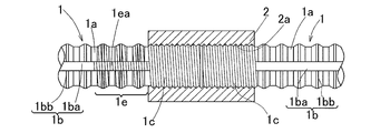
- the threaded reinforcing bar joint of the deformed reinforcing bar is a reinforcing bar joint in which a pair of reinforcing bars 1 and 1 are connected by a screw cylinder 2.
- the reinforcing bars 1 are deformed reinforcing bars having ribs 1ba extending along the length direction and protrusions 1b such as nodes 1bb extending in the circumferential direction on the outer peripheral surface of the reinforcing bar main body 1a.
- the nodes 1bb are provided at regular intervals apart in the length direction.
- the ribs 1ba extending in the length direction are provided at two locations separated in the circumferential direction, but may be provided at three to four locations separated in the circumferential direction.
- the node 1bb is formed in a circular shape over the entire circumference.
- the node 1bb may be a semicircular shape, and radial nodes located in the half circumference portion of the reinforcing bar outer circumference and the remaining half circumference portion may be alternately provided in the length direction. good.
- the opposing ends of the pair of reinforcing bars 1 and 1 connected to each other have a diameter-enlarging portion W1d that is not more than the outermost diameter D1 of the reinforcing bar including the protrusion 1b and not less than the outer diameter D2 of the reinforcing bar body.
- the enlarged diameter portion W1d is a male threaded portion 1c that is threaded.
- the male screw portion 1c is a rolled screw.
- the diameter increasing portion W1d for forming the protrusion 1b of the reinforcing bar 1 and the male screw portion 1c is manufactured by roll forming when the reinforcing bar 1 is manufactured, as will be described later.
- the male screw portion 1c is The outer diameter of the enlarged diameter portion W1d to be formed is 16.3 mm.
- the outer diameter of the male thread portion 1c of the reinforcing bar 1 is not more than the outermost diameter D1 of the reinforcing bar and not less than the outer diameter D2 of the reinforcing bar main body in the completed state.
- the diameter does not need to be equal to or smaller than D1, and may be equal to or smaller than the outermost diameter D1 of the reinforcing bar in the state of the enlarged diameter portion W1d before rolling.
- the outer diameter of the thread after rolling may be larger than the outer diameter of the material, and the outer diameter of the enlarged diameter portion W1d is restricted by rolling the male screw portion 1c. This is for reasons of convenience in the roll forming process prior to.
- the groove bottom diameter of the male screw portion 1c of the reinforcing bar 1 is set to be equal to or larger than the outer diameter D2 of the reinforcing bar main body of the reinforcing bar 1.
- the male screw portions 1c of both the reinforcing bars 1 have the same diameter, the same pitch, and the same spiral direction, and the length L1 of the male screw portion 1c of each reinforcing bar 1 is the length of the screw cylinder.
- the length is a length obtained by adding a gap generated between the end faces of both the reinforcing bars 1 and 1 to L2.
- the diameter, pitch, and spiral direction may differ between the external thread parts 1c and 1c of both the reinforcing bars 1.
- the male screw portions 1c and 1c of both the reinforcing bars 1 may be reverse screws.
- a portion following the base end of the male screw portion 1c of each reinforcing bar 1 is a relief screw portion 1e.
- the escape screw portion 1e is formed by rolling a helical relief groove 1ea that fits into the threads 1b of the female screw portion 2a of the screw cylinder 2 on the ribs 1ba and the joints 1bb of the outer peripheral surface of the reinforcing bar 1. It is the part which did.
- the length L3 of the escape screw portion 1e is a length obtained by subtracting the length L1 of the male screw portion 1c from the length L2 of the screw tube 2, or a length slightly longer than this.
- the cross-sectional shape of the spiral escape groove 1ea is the same as that of the screw groove of the male screw portion 1c, but it need not be a shape that contributes to screw coupling. Any cross-sectional shape that can release the screw thread of the screw cylinder 2 may be used, or a cross-sectional shape in which a large gap is generated at the meshing portion between the screw threads.
- the groove bottom diameter of the spiral relief groove 1ea of the escape screw portion 1e is not less than the outer diameter D2 of the reinforcing bar main body 1a, but may be less than the outer diameter D2 of the reinforcing bar main body 1a due to processing errors or the like. . This is because the spiral relief groove 1ea is processed by rolling, so that the cross-sectional dimension of the reinforcing bar 1 does not change regardless of the groove bottom diameter.
- the escape screw portion 1e may be provided only on one of the reinforcing bars 1 and 1 on both sides to be screwed into the screw cylinder 2, and as shown in FIG. Both the reinforcing bars 1 and 1 do not need to be provided with the escape screw portion 1e.
- the screw cylinder 2 is a steel cylindrical body in which a female screw portion 2a is continuously formed on the inner circumference over substantially the entire length. In addition, it is good also as a reverse screw as mentioned above.
- the cross-sectional shapes of the internal thread portion 2a of the screw cylinder 2 and the external thread portion 1c of the reinforcing bar 1 may be triangular, trapezoidal, rectangular, or curved.
- Each rebar 1 has the male screw portions 1c and 1c formed at both ends, for example, having a plurality of standard dimensions, but may have a male screw portion 1c formed only at one end.
- the male thread portion 1 c of the reinforcing bar 1 may be used to form a diameter-reinforcing reinforcing bar head 1 ⁇ / b> T for fixing to concrete.
- the fixing plate 3 may be screwed with the female screw portion 3 a formed on the inner periphery of the fixing plate 3.
- the enlarged diameter reinforcing bar head 1T includes a fixing plate 3 and a fixing plate 4 serving as a lock nut that is overlapped with the fixing plate 3 and screwed into the male screw portion 1c of the reinforcing bar 1. Note that the fixing plate 4 is not necessarily provided.
- the screw cylinder 2 of the reinforcing bar joint is screwed into the male threaded portion 1c at the other end of the reinforcing bar 1.
- the male screw portions 1 c at both ends of the reinforcing bar 1 may be enlarged diameter heads 1 ⁇ / b> T by the fixing plate 3 and the fixing plate 4.
- the enlarged diameter portion W1d is equal to or smaller than the outermost diameter D1 of the reinforcing bar, which is the outer diameter included, and larger than the outer diameter D2 of the reinforcing bar main body 1a of the other part.
- the length range L0 to be the enlarged diameter portion W1d is a length obtained by adding a cutting allowance for subsequent separation to twice the length L1 of the male screw portion 1c.
- this material deformed reinforcing bar W1 forms a protrusion 1b by rolling by roll forming by passing an iron round bar-like wire rod W0 as a material between forming rolls 11 and 11. This shaping is performed while heating the wire W0.
- the diameter-enlarged portion W 1 d is provided in the process of roll forming by the forming rolls 11, 11, the diameter-enlarged portion W 1 d is provided.
- the forming rolls 11 and 11 are provided with a recess (not shown) for forming the protrusion 1b of the reinforcing bar 1 on the outer peripheral surface serving as a forming die surface.
- 11 is a part in the circumferential direction on the outer peripheral surface of the outer peripheral surface 11a, and is defined as a diameter-enlarged portion forming recess 11a.
- the circumferential length of the enlarged diameter portion forming recess 11a is the length (L0) of the enlarged diameter portion W1d to be molded.
- the material deformed reinforcing bar in a heated state in contact with the protrusion 1b of the deformed reinforcing bar W1 of the material deformed by roll forming of the long deformed reinforcing bar W1 as the material.
- the deformed reinforcing bar W1 is manufactured without causing the problem of the bending of the deformed reinforcing bar W1 due to the diameter expanding part W1d not contacting the guide 12 such as a roll that guides W1. be able to.
- the deformed reinforcing bar W1 that is the material thus manufactured is cut in the middle of each enlarged diameter portion W1d, and a plurality of deformed reinforcing bars W1 ′ with an enlarged diameter portion having a predetermined length having enlarged diameter portions W1d at both ends.
- the deformed reinforcing bar W1 ′ having an enlarged diameter portion having a predetermined length is, for example, a multiple of a module (eg, 910 mm, 1000 mm, etc.) of a module designed for building when applied to a building foundation such as a house, or the module Is preferably a multiple of 1/2 the length.
- the male threaded portion 1c is processed by rolling between the pair of rolling rolls 13 and 13 as shown in FIG. 9 in the diameter-enlarged portion W1d of each of the cut deformed reinforcing bars W1 ′.
- Reinforcing bar 1 having a male threaded portion 1c whose diameter has been increased.
- the pair of rolling rolls 13 and 13 are arranged apart from each other as shown in the figure, and after the enlarged diameter portion W1d is positioned between the rolling rolls 13 and 13, both rolling rolls 13 are provided. , 13 are moved in the radial direction as indicated by arrows and pressed against the enlarged diameter portion W1d while rotating.
- the deformed reinforcing bar W1 ′ with an enlarged diameter portion is fed between the rolling rolls 13 and 13 even after the male screw portion 1c is rolled, and the escape screw portion 1e following the male screw portion 1c (FIG. 1A). Roll.
- the end portion of the reinforcing bar 1 is the male threaded portion 1c that is threaded as the diameter-expanded portion W1d
- the diameter of the male threaded portion 1c is larger than that of the threaded portion as it is. Is thick and the strength of the connecting portion is secured.
- the male threaded portion 1c is processed into a rebar expanded diameter portion W1d.
- the expanded diameter portion W1d is equal to or smaller than the outermost diameter D1 of the rebar including the protrusion 1b of the deformed rebar 1, the material deformed rebar W1.
- It can be manufactured as a reinforcing bar with a diameter-enlarging part at the time of manufacture. That is, as described above with reference to FIG. 8, when the material deformed reinforcing bar W1 is roll-formed, the reinforcing bar moving in the length direction in the heated state of red heat is guided in contact with the guide 12 by the protrusion 1b on the outer peripheral surface. However, if there is an enlarged diameter portion having an outer diameter equal to or greater than the protrusion 1b, the enlarged diameter portion is lifted in contact with the guide, and the reinforcing bar is bent. This bend remains to some extent even after the rebar is cooled, resulting in a deformed rebar with a bend.
- the male thread portion 1c of the reinforcing bar 1 is a rolled screw, unlike the case where the thread groove is cut, the material is not removed, and the cross-sectional area is offset between the thread groove and the thread, and the diameter-enlarged portion W1d.
- the effect of reinforcement by expanding the diameter can be enhanced as much as possible.
- the screw cylinder 2 is deeply screwed into the male threaded portion 1c of one reinforcing bar 1 until the screw cylinder 2 does not protrude from the end face of the reinforcing bar 1.
- the reinforcing bars 1 and 1 on both sides are arranged in a substantially butted state.
- the screw cylinder 2 is unscrewed and screwed over the male screw portions 1c and 1c of the reinforcing bars 1 and 1 on both sides. Thereby, joining is completed.
- the groove bottom diameter of the screw groove is smaller than the outermost diameter D1 of the reinforcing bar. Therefore, as shown in FIG. 1B, when the screw cylinder 2 is deeply screwed into the male thread portion 1c of one reinforcing bar to a position where it does not protrude from the end face, the screw cylinder 2 interferes with the protrusion 1b of the deformed reinforcing bar 1. Problems arise.
- the thread of the female screw portion 2a of the screw cylinder 2 interferes with the rib 1ba and the node 1bb.
- the screw cylinder 2 can be screwed deeply.
- the formation of the escape screw portion 1e causes a cross-sectional defect in the rib 1ba or the like, but the escape screw portion 1e is processed by rolling, so that the problem due to the cross-sectional defect does not occur. That is, among the protrusions 1b of the deformed reinforcing bar 1, the rib 1ba which is a protrusion extending along the length direction contributes to the cross-sectional area of the reinforcing bar, and the spiral relief groove is formed in the rib by cutting or the like. When it is formed, the cross-sectional defect is generated accordingly, and there is a possibility that the portion becomes insufficient in strength when a tensile force is applied.
- the reinforcing bar material for the cross-sectional defect generated in the rib 1ba by threading is plastically flowed in a circumferential direction portion different from the rib 1ba at the same length direction position. Therefore, the cross-sectional area of the entire rebar is constant regardless of the processing of the spiral relief groove 1ea. Therefore, the problem that the strength is reduced due to the formation of the spiral relief groove is avoided.
- the manufacturing method of the above-mentioned threaded deformed reinforcing bar it is manufactured as a reinforcing bar with a diameter-enlarging portion W1d when the deformed reinforcing bar W1 as a material is manufactured. Therefore, it is not necessary to provide a diameter expansion processing facility separately from the reinforcing bar manufacturing facility, the facility can be simplified, and the productivity is excellent. Since the enlarged diameter portion W1d is equal to or smaller than the outermost diameter D1 of the reinforcing bar including the protrusion 1b, it can be manufactured as a reinforcing bar with an enlarged diameter portion when the deformed reinforcing bar W1 is manufactured.
- the male threaded portion 1c is rolled, unlike the case where the thread groove is cut, the material is not removed, the cross-sectional area is offset between the thread groove and the thread, and the diameter-enlarged portion is less than the outermost diameter of the reinforcing bar. In such a limited range, the effect of reinforcement by diameter expansion can be enhanced as much as possible.
- the enlarged diameter portion W1d is formed in the manufacturing process of the deformed reinforcing bar W1 as described above when the outer diameter D2 of the reinforcing bar main body is 32 mm or less.
- the reinforcing bar has an outer diameter of 32 mm or less, the work of forming the enlarged diameter portion W1d in the manufacturing process of the deformed reinforcing bar W1 can be easily performed without causing distortion or the like.
- Such a small-diameter deformed reinforcing bar 1 is used for a cloth foundation of a house, and the threaded reinforcing bar joint of the above embodiment can be used effectively.
- grades are determined by building standards, etc. depending on the place of use, etc., but not for high grades such as SA grade and A grade, but for lower grade B grade or less reinforcing joints such as SA grade and A grade. High accuracy is not required compared to the class. With a small diameter (small diameter), there is little backlash and the class A can be secured sufficiently.
- the reinforcing bars 1 and 1 on both sides to be connected are formed by rolling the male screw part 1c on the enlarged diameter part W1d, but one reinforcing bar is provided with the male screw on the enlarged diameter part W1d.
- the reinforcing bar is not limited to the reinforcing bar having the portion, and may be a reinforcing bar having a male screw.
- the large-diameter side reinforcing bar 1A has a rounded end portion and a male thread portion formed in the rounded portion. It may be a reinforcing bar.
- FIGS. 11 to 14 further show a fifth embodiment.
- the deformed reinforcing bar threaded reinforcing bar joint is obtained by increasing the outer diameter of the reinforcing bar main body 1 a from the general part 1 f of the reinforcing bar 1 in the portion of the reinforcing bar 1 as the escape screw portion 1 e. is there.
- FIG. 12 shows the shape of the reinforcing bar before rolling of the male screw portion 1c and the helical relief groove 1ea.
- the portion where the escape screw portion 1e in the material deformed reinforcing bar W1 is formed is denoted by “1g”.
- the outer diameter (radius) R2 'of the portion that becomes the escape screw portion 1e is larger than the outer diameter (radius) R2 of the minimum diameter portion of the rebar main body 1a of the general portion 1f.
- the depth H2 that becomes the valley between the adjacent nodes 1bb is made shallower than the depth H1 that becomes the valley in the general portion 1f.
- the reinforcing bar 1 has, in the middle of the reinforcing bar length direction, the enlarged diameter part W1d ′ having the same diameter as the enlarged diameter part W1d that forms the external thread part 1c and no male thread part 1 It is provided in a place or a plurality of places.
- the intermediate diameter enlarged portion W1d ′ is approximately twice as long as the length L1 of the male screw portion 1c, specifically, a length L0 obtained by adding a cutting margin to twice the length L1 of the male screw portion 1c.
- the pitch of the enlarged diameter portions W1d and W1d ′ is, for example, an integral multiple of a building module (eg, 910 mm, 1000 mm, etc.).
- the reference numerals “W1d” and “W1d ′” of the diameter-enlarged portion are shown with “′” and without “′” for distinction between the middle portion and the end portion. In other cases, the symbol “′” may be omitted.
- a circumferential groove 6 is provided at the center in the length direction of each intermediate diameter enlarged portion W1d ′.
- the cross-sectional shape of the circumferential groove 6 is, for example, a trapezoidal shape.
- the groove width B6 is, for example, 3 mm in any of the reinforcing bars of 16D, 19D, and 22D.
- the rebar 1 of FIG. 14 is performed by the roll formation described above with reference to FIG.
- the circumferential groove 6 is also formed at the time of roll formation by providing a circumferential groove mold (not shown) on the forming roll 11. Further, in this roll forming, the material deformed reinforcing bar W1 having the diameter-enlarged portions W1d (W1d ′) at a plurality of positions in the middle in the length direction is roll-formed by a plurality of rotations of the roll forming roll 11, and an arbitrary place
- the material deformed reinforcing bar W1 is cut by the circumferential groove 6 of the enlarged diameter portion W1d (W1d ′), and the male screw portion 1c is rolled into the enlarged diameter portion W1d of the cut portion.
- the rest of the configuration in this embodiment and the configuration specifically described below are the same as in the embodiment described above with reference to FIGS. 1A, 1B, and 1C.
- the portion of the reinforcing bar 1 as the escape screw portion 1e has the outer diameter of the reinforcing bar main body 1a larger than the general portion 1f of the reinforcing bar 1, that is, R2 '> R2 in FIGS. 13B and 13C. Even if an excessive tensile load is applied to the reinforcing bar 1, the joint portion (the male screw portion 1c and the relief screw portion 1e) does not break at the end, and the breakage occurs in the general portion 1f.
- the diameter of the male screw part 1c is the same as that of the enlarged diameter part W1d forming the male screw part 1c. Since the conversion portion W1d ′ is provided, the following advantages are obtained. That is, when the material deformed reinforcing bar W1 having the enlarged diameter portion W1d is roll-formed as described above with reference to FIG. 8, the enlarged diameter portion W1d is formed for each outer peripheral length of the forming roll 11. Therefore, in the material deformed reinforcing bar W1 longer than the outer peripheral length of the forming roll 11, the diameter-enlarged portion W1d exists in the middle of the reinforcing bar length direction.
- the deformed steel bar W1d having a diameter-enlarged portion W1d in the middle is easily obtained by roll formation. it can. Even if there is an enlarged diameter portion W1d in the middle, it may be embedded in the concrete when using reinforcing bars. At this time, since the diameter-enlarged portion W has a simple round bar shape, the adhesion to concrete is lower than that of the deformed portion. However, when the circumferential groove 6 is provided at the center of the diameter-enlarged portion as described above, it becomes the same as when one node portion is provided, and the adhesion is increased. Further, the circumferential groove 6 at the center of the enlarged diameter portion W1d functions as a mark for cutting when the male threaded portion 1c is formed by cutting, leading to improvement in cutting workability.
- Reinforcing bar 1 of this example has the same length L1 as the length of male threaded portion 1c, and the length of intermediate enlarged male threaded portion W1d (W1d ') shown in FIG. It is.
- Other configurations are the same as the reinforcing bar 1 described with reference to FIG.
- FIG. 15A A method for manufacturing the threaded deformed reinforcing bar 1 of FIG. 16 will be described with reference to FIG.
- This rebar 1 is performed by the roll formation described above with reference to FIG. 8, similarly to the rebar 1 of FIG. 14.
- the material deformed reinforcing bar W1 having the diameter-enlarged portion W1d having the length L1 is roll-formed at a plurality of intermediate positions in the length direction by a plurality of rotations of the roll forming roll 11 (FIG. 15A).
- the material deformed reinforcing bar W1 is cut at the end of the enlarged diameter portion W1d at an arbitrary location as shown in FIG.
- the enlarged diameter portion forming concave portions 11 a on the outer peripheral surface of the forming roll 11 are provided at a plurality of locations in the circumferential direction, and the diameter is increased by one rotation of the forming roll 11.
- a plurality of forming portions W1d may be formed.
- Other configurations in this embodiment are the same as those in the embodiment described above with reference to FIGS.
- the reinforcing bar 1 having the diameter-enlarged portion W1d having the male screw portion length L1 in the middle is used as the relief 1 adjacent to the diameter-enlarged portion W1d as shown in FIGS.
- the threaded portion 1e may be formed on only one side of the enlarged diameter portion W1d, and the material deformed reinforcing bar W1 may be roll-formed on the other side so that the general portion 1f directly follows the enlarged diameter portion W1d.
- the escape screw non-formed portion shorter than the escape screw portion 1e is provided on the other side. 1 g may be provided.
- the escape screw non-formed portion 1g is a portion in which the outer diameter of the reinforcing bar main body 1a is larger than that of the general portion 1f and the male screw is not formed, like the escape screw portion 1e.
- FIG. 20 shows a deformed reinforcing bar screw-type reinforcing bar joint according to the ninth embodiment of the present invention.
- the portion following the enlarged diameter portion W1d in which the male screw portion 1c of the reinforcing bar 1 is formed is not a relief screw portion, but is a general portion 1f.
- the male screw portions 1c and 1c of the pair of reinforcing bars 1 and 1 connected by the screw cylinder 2 are mutually reverse screws.
- the screw cylinder 2 has the center in the length direction as a boundary, and the female screw portions 2a and 2a on both sides of the screw cylinder 2 are reverse screws.
- the cross-sectional area of the reinforcing bar 1 is (male screw portion 1c)> (relief screw portion 1e) ⁇ (general portion 1f).
- the cross-sectional area of the reinforcing bar main body 1a of the screw portion 1e may be increased so that (relief screw portion 1e)> (male screw portion 1c)> (general portion 1f).
- the cross-sectional area of each part of the reinforcing bar 1 referred to here is the cross-sectional area of the part that is the minimum cross-section of each part.
- the screw groove portion has a small diameter due to the formation of the screw groove.
- the screw groove has a spiral shape, in the cross section of the reinforcing bar 1, the half circumference becomes a screw groove, Since the remaining half circumference is a thread formed on the node 1ba, the influence of the cross-section lowering due to the formation of the thread groove is small.
- FIG. 21 shows a tenth example of a threaded reinforcing bar joint that connects reinforcing bars of different diameters.
- the description will be made assuming that the code of the rebar 1 on the small diameter side is “1S” and the code of the rebar 1 on the large diameter side is “1L”.
- the screw cylinder 2 is the same as the screw-type reinforcing bar joint that connects the small-diameter-side reinforcing bar 1S.
- the small-diameter rebar 1S that is screwed into the screw cylinder 2 has a male screw portion 1c that connects the rebars 1 and 1 of the same diameter shown in FIGS. 11 to 14 and an escape screw portion 1e.
- the male threaded portion 1c ′ of the large-diameter rebar 1L that is screwed into the screw cylinder 2 has a true diameter of the same outer diameter as that of the enlarged-diameter portion W1d (FIG. 7) of the small-diameter rebar 1S at the end of the rebar 1L.
- a circular part is formed, and the outer periphery of the perfect circular part is formed by rolling.
- the threaded reinforcing bar joint A that connects the large diameter side reinforcing bars 1L is the same as the example of FIG. 1A.
- the screw-type reinforcing bar joint (not shown in FIG. 21) for connecting the small diameter side reinforcing bars 1S is the same as the example of FIG. 1A.
- the small diameter side reinforcing bar 1S is D16
- the large diameter side reinforcing bar 1L is D19.
Abstract
Description
そのため、特殊継手として、スリーブ内に鉄筋と共にグラウトを注入する継手が開発されている。このグラウトを注入する特殊継手は、配筋構造の簡略化の面で好ましく、実用化されているが、グラウトの硬化に、例えば1日程度の養生期間が必要になり、工期が長びくという欠点がある。 In reinforced concrete, deformed reinforcing bars are generally used as reinforcing bars. In long columns, beams, fabric foundations, etc., various reinforcing bar joints are used in order to make a limited length of reinforcing bars continuous in the field. As the reinforcing bar joint, a lap joint or a gas pressure welding joint in which the reinforcing bars are stacked by a predetermined length is generally used. However, the lap joint has a complicated bar arrangement structure due to the overlap, and the gas pressure joint has a drawback that the quality of the joint depends on the skill of the pressure welding.
Therefore, as a special joint, a joint has been developed in which grout is injected into the sleeve together with the reinforcing bar. This special joint for injecting grout is preferable in view of simplification of the bar arrangement structure, and has been put to practical use. However, for curing the grout, for example, a curing period of about one day is required and the construction period is long. is there.
異形鉄筋である少なくとも一方の鉄筋は、素材となる鉄製の線材のロール成形により前記外周面の突条を成形すると共に長さ方向の一部に他の部分よりも拡径した拡径化部を成形し、この拡径化部の外径を前記鉄筋の前記突条を含む鉄筋最外径以下とし、この拡径化部に転造により前記雄ねじ部を形成している。 The threaded reinforcing bar joint of the deformed reinforcing bar of the present invention is a reinforcing bar joint for connecting a pair of reinforcing bars, and has a male threaded portion at the opposite end of the pair of reinforcing bars connected to each other, and extends over the male threaded portion of both reinforcing bars. A screw cylinder to be screwed together, and at least one of the pair of reinforcing bars is a deformed reinforcing bar having a protrusion on the outer peripheral surface of the reinforcing bar body,
At least one reinforcing bar that is a deformed reinforcing bar is formed by forming a protrusion on the outer peripheral surface by roll forming of an iron wire material, and having a diameter-enlarged portion that is larger in diameter than the other part in the length direction. The outer diameter of the enlarged diameter portion is formed to be equal to or less than the outermost diameter of the reinforcing bar including the protrusion of the reinforcing bar, and the male screw portion is formed by rolling the enlarged diameter portion.
前記異形鉄筋の前記逃がし用ねじ部とした部分は、異形鉄筋における一般部分よりも鉄筋本体の外径を大きくすることが好ましい。 In the present invention, at least one of the deformed reinforcing bars is a helical relief that fits a portion of the outer thread on the outer surface of the threaded part of the threaded portion of the threaded cylinder. It is good also as an escape thread part in which the groove | channel was formed by rolling. The length of the escape screw portion is preferably equal to or longer than the length of the screw cylinder minus the length of the male screw portion. The helical relief groove does not need to have a shape that contributes to screw connection, and may have any cross-sectional shape that can release the screw thread of the screw cylinder, and has a cross-sectional shape that causes a large gap in the meshing portion. Also good.
It is preferable that the part of the deformed reinforcing bar as the escape screw part has a larger outer diameter of the reinforcing bar body than the general part of the deformed reinforcing bar.
すなわち、異形鉄筋の突条を含む径である鉄筋最外径以下の拡径化部に雄ねじ部を形成した場合、これに螺合するねじ筒を雄ねじ部よりも奥側までねじ込もうとしても、ねじ筒の雌ねじ部内径が鉄筋最外径以下となるため、ねじ筒のねじ山が異形鉄筋の突条に干渉し、雄ねじ部よりも奥側にねじ込むことができない。この干渉を、前記逃がし用ねじ部で回避することができる。 As described above, when the escape screw portion is provided, the screw tube protrudes from one of the reinforcing bars without causing a problem of interference with the deformed reinforcing bar protrusion when connecting with the screw tube. It is possible to screw over the reinforcing bars on both sides by screwing in the far side to the position where it does not, screwing the other reinforcing bar to the end of the one reinforcing bar and then screwing it back. According to such a connection method, when the screw cylinder is rotated and joined, it is not necessary to move the rebar greatly with screwing.
That is, when a male thread part is formed in the diameter-enlarged part of the reinforcing bar outer diameter that is the diameter including the protrusion of the deformed reinforcing bar, even if it is attempted to screw the screw cylinder to be screwed into the deeper side than the male thread part Since the internal diameter of the female thread portion of the screw cylinder is equal to or less than the outermost diameter of the reinforcing bar, the thread of the screw cylinder interferes with the protrusion of the deformed reinforcing bar and cannot be screwed into the back side of the external thread part. This interference can be avoided by the escape screw portion.
ただし、この部分で終局時に破断することは好ましくなく、異形鉄筋の前記逃がし用ねじ部とした部分は、異形鉄筋における一般部分よりも鉄筋本体の外径を大きくするのが良い。例えば、リブ断面積に相当する断面積を、谷部を浅くしてカバーするのが良い。 Moreover, the rib which is a protrusion extended along a length direction among the protrusions of a deformed reinforcing bar contributes to the cross-sectional area of a reinforcing bar, and when the said helical relief groove | channel is formed in the said rib by cutting etc. In such a case, a cross-sectional defect is generated accordingly, and there is a possibility that the portion becomes insufficient in strength when a tensile force is applied. However, when the helical relief groove is formed by rolling, the reinforcing bar material corresponding to the cross-sectional defect generated in the rib by the threading process plastically flows to the circumferential portion different from the rib at the same length direction position. Thus, the cross-sectional area of the entire rebar is constant regardless of the processing of the spiral relief groove. Therefore, the problem that the strength is reduced due to the formation of the spiral relief groove is avoided.
However, it is not preferable to break at this part at the end, and the outer diameter of the reinforcing bar main body is preferably larger than the general part of the deformed reinforcing bar. For example, the cross-sectional area corresponding to the rib cross-sectional area may be covered by shallowing the valleys.
これにつき、鉄筋外周面の突条に螺旋状逃がし溝を転造した構成であると、継手の接続作業の容易性と、コンクリート付着機能との二つの機能を共に得ることができる。 In addition, it is possible to screw the screw cylinder into a position where it does not protrude from the end of the reinforcing bar by increasing the length of the male threaded part. Compared to the cross-sectional shape of the concrete, the adhesion performance of concrete is reduced. It is necessary to secure the adhesion performance of the concrete, which is the greatest function of the deformed reinforcing bar, at the location not used as the reinforcing bar joint.
In this regard, when the spiral relief groove is rolled on the protrusion on the outer peripheral surface of the reinforcing bar, two functions of the joint connection work and the concrete adhesion function can be obtained.
この構成の場合、ねじ式鉄筋継手につき上述したと同様に、ねじ筒を雄ねじ部よりも奥側にねじ込んでおいてねじ戻す接続作業が行えて、接続作業性が向上し、かつ異形鉄筋のコンクリート付着機能も確保できるという利点が得られる。 In the threaded deformed reinforcing bar according to the present invention, the threaded deformed reinforcing bar includes a screw thread in a female thread portion of a threaded cylinder that is screwed into a protruding portion of an outer peripheral surface of the threaded deformed reinforcing bar with the male thread portion. It is good also as the screw part for relief in which the helical relief groove | channel which fits was formed by rolling.
In the case of this configuration, in the same manner as described above for the screw-type reinforcing bar joint, it is possible to perform a connecting operation by screwing the screw tube deeper than the male threaded portion and unscrewing it, improving the connecting workability, and deformed reinforcing bar concrete There is an advantage that the adhesion function can be secured.
前記拡径化部を有し前記雄ねじ部が未加工の状態の鉄筋をロール成形する場合、ロールの外周長さ毎に前記拡径化部が形成されることになる。そのため、ロールの外周長さよりも長い異形鉄筋では、鉄筋の長さ方向の中間に拡径化部が存在することになるが、この鉄筋中間の拡径化部は、雄ねじ部を未加工として残し、鉄筋使用時にはコンクリート内に埋め込むようにしても良い。 In the threaded deformed reinforcing bar of the present invention, in the middle of the longitudinal direction of the reinforcing bar, it may have the same diameter as the diameter-enlarging part that forms the male thread part, and the male thread part may have an unformed diameter-enlarging part. good.
When roll forming a reinforcing bar having the diameter-enlarged portion and the male screw portion being unprocessed, the diameter-enlarged portion is formed for each outer peripheral length of the roll. Therefore, in deformed reinforcing bars longer than the outer peripheral length of the roll, there will be an enlarged diameter part in the middle of the reinforcing bar length direction, but the enlarged diameter part in the middle of the reinforcing bar leaves the male thread part unprocessed. When using reinforcing bars, they may be embedded in concrete.
長さ方向の中間の拡径化部の長さは、雄ねじ部の長さの約2倍の長さ、具体的には雄ねじ部の長さの2倍に切断代を加えた長さとすることで、拡径化部で2分割し、雄ねじ部を転造すれば、鉄筋端部の雄ねじ部とできる。このため、ロール成形時には、製品となる鉄筋長さに係わらずにロール成形を行い、その後に製品となる鉄筋長さ毎に切断して複数本の鉄筋を得るにつき、拡径化部の中央で切断し、この中央で切断された拡径化部に雄ねじ部を転造することで、効率良く希望の長さの鉄筋を生産することができる。 The diameter-enlarged portion that is not formed with the male screw portion provided in the middle of the length direction of the reinforcing bar may be approximately twice as long as the length of the male screw portion. It is preferable to provide a circumferential groove at the center in the length direction of the intermediate diameter enlarged portion.
The length of the diameter-enlarged portion in the middle of the length direction should be approximately twice the length of the male screw portion, specifically, twice the length of the male screw portion plus the cutting allowance. Thus, if the diameter-enlarged part is divided into two and the male thread part is rolled, the male thread part at the end of the reinforcing bar can be obtained. For this reason, at the time of roll forming, roll forming is performed regardless of the length of the reinforcing bar to be the product, and then cutting is performed for each reinforcing bar length to be the product to obtain a plurality of reinforcing bars. By cutting and rolling the male screw part into the enlarged diameter part cut at the center, a reinforcing bar having a desired length can be efficiently produced.
鉄筋1の突条1b、および雄ねじ部1cを成形する前記拡径化部W1dは、後述のように、鉄筋1の製造時にロール成形により製造される。
寸法例を説明すると、鉄筋1の鉄筋本体の外径D2が15.2mm、鉄筋最外径D1が17.6mm(リブ1ba、節1bbの高さが1.2mm)の場合、雄ねじ部1cを形成する拡径化部W1dの外径は、16.3mmとされる。 The opposing ends of the pair of reinforcing
The diameter increasing portion W1d for forming the
Explaining the dimension example, when the outer diameter D2 of the reinforcing bar body of the reinforcing
螺旋状逃がし溝1eaの断面形状は、この例では雄ねじ部1cのねじ溝と同じ形状としているが、ねじ結合に寄与する形状である必要はない。ねじ筒2のねじ山を逃がすことができる断面形状であれば良く、ねじ山間の噛み合い部分に隙間が大きく生じる断面形状であっても良い。 A portion following the base end of the
In this example, the cross-sectional shape of the spiral escape groove 1ea is the same as that of the screw groove of the
鉄筋1の他端の雄ねじ部1cには、鉄筋継手の前記ねじ筒2を螺合させる。なお、鉄筋1の両端の雄ねじ部1cを、定着板3や固定板4による拡径頭部1Tとしても良い。 As shown in FIGS. 5 and 6, the
The
しかし、この実施形態では、鉄筋1の雄ねじ部1cに続く部分は、続く逃がし用ねじ部1eとされているので、リブ1baや節1bbにねじ筒2の雌ねじ部2aのねじ山が干渉することなく、ねじ筒2を深くねじ込むことができる。 Further, since the
However, in this embodiment, since the portion following the
例えば、図10に示すように、異なる径の鉄筋1,1A間の接続の場合、その大径側の鉄筋1Aは、端部を真円加工し、その真円加工部に雄ねじ部を形成した鉄筋であっても良い。 Further, in each of the above embodiments, the reinforcing
For example, as shown in FIG. 10, in the case of connection between the reinforcing
この実施形態におけるその他の構成、および以下に特に説明した構成の他は、図1A,1B,1Cと共に前述した実施形態と同様である。 The
The rest of the configuration in this embodiment and the configuration specifically described below are the same as in the embodiment described above with reference to FIGS. 1A, 1B, and 1C.
すなわち、拡径化部W1dを有する素材異形鉄筋W1を図8と共に前述したようにロール成形する場合、成形用ロール11の外周長さ毎に拡径化部W1dが形成されることになる。そのため、形成用ロール11の外周長さよりも長い素材異形鉄筋W1では、鉄筋長さ方向の中間に拡径化部W1dが存在することになる。したがって、中間に拡径化部W1dを有しない素材異形鉄筋を成形することは困難であるが、中間に拡径化部W1dを有する素材異形鉄筋W1dであれば、ロール形成で容易に得ることができる。中間に拡径化部W1dがあっても、鉄筋使用時にはコンクリート内に埋め込めば良い。このとき、拡径化部Wは、単なる丸棒状であるため、異形部分に比べてコンクリートに対する付着力が低い。しかし、上記のように拡径化部の中央に円周溝6を設けると、節部が1箇所設けられたと同様になり、付着力が増す。また、この拡径化部W1dの中央の円周溝6は、切断して雄ねじ部1cを形成する場合には、切断の目印として機能し、切断作業性の向上に繋がる。 Moreover, in the reinforcing
That is, when the material deformed reinforcing bar W1 having the enlarged diameter portion W1d is roll-formed as described above with reference to FIG. 8, the enlarged diameter portion W1d is formed for each outer peripheral length of the forming
この実施形態におけるその他の構成、図11~図14等と共に前述した実施形態と同様である。 When roll forming is performed as shown in FIG. 8, the enlarged diameter portion forming
Other configurations in this embodiment are the same as those in the embodiment described above with reference to FIGS.
この実施形態のように、ねじ筒2で接続される一対の鉄筋1,1の雄ねじ部1c,1cを逆ねじとした場合は、ねじ筒2の回転によって両側の鉄筋1,1が引き寄せられることになり、ねじ筒2は両側に鉄筋1,1の雄ねじ部1c,1cに同時に先端からねじ込まれることになるため、逃がし用ねじ部1eを設なくても接続が簡単に行える。この実施形態におけるその他の構成,効果は、図1A等に示した第1の実施形態と同等である。 FIG. 20 shows a deformed reinforcing bar screw-type reinforcing bar joint according to the ninth embodiment of the present invention. In this example, the portion following the enlarged diameter portion W1d in which the
When the
図21の例では、ねじ筒2は、小径側の鉄筋1Sを接続するねじ式鉄筋継手と同じものを用いている。このねじ筒2に螺合する小径側の鉄筋1Sは、図11~図14の同径の鉄筋1,1同士を接続する雄ねじ部1cおよび逃がし用ねじ部1eを有する構成とされている。前記ねじ筒2に螺合する大径側の鉄筋1Lの雄ねじ部1c′は、この鉄筋1Lの端部に、小径側の鉄筋1Sの拡径化部W1d(図7)と同じ外径の真円部を形成し、その真円部の外周に転造により形成している。大径側の鉄筋1L同士を接続するねじ式鉄筋継手Aは、図1Aの例と同じである。また、小径側の鉄筋1S同士を接続するねじ式鉄筋継手(図21には図示せず)についても、図1Aの例と同じである。 FIG. 21 shows a tenth example of a threaded reinforcing bar joint that connects reinforcing bars of different diameters. In this example, the description will be made assuming that the code of the
In the example of FIG. 21, the
1a…鉄筋本体
1b…突条
1ba…リブ
1bb…節
1c…雄ねじ部
1e…逃がし用ねじ部
1ea…螺旋状逃がし溝
1f…一般部分
1g…逃がし用ねじ未形成部
1s…端材鉄筋
2…ねじ筒
3…定着板
6…円周溝
11…成形用のロール
12…ガイド
13…転造用ロール
A,B,C…ねじ式鉄筋継手
D1…鉄筋最外径
D2…鉄筋本体の外径
L1…雄ねじ部の長さ
L2…ねじ筒全長
W0…線材
W1…素材となる長尺の異形鉄筋
W1d,W1d′…拡径化部 DESCRIPTION OF
Claims (13)
- 一対の鉄筋を接続する鉄筋継手であって、互いに接続される一対の鉄筋の対向する端部に雄ねじ部を有し、両鉄筋の雄ねじ部に渡って螺合するねじ筒を設けてなり、
前記一対の鉄筋のうち、少なくとも一方の鉄筋は、鉄筋本体の外周面に突条を有する異形鉄筋であり、
異形鉄筋である少なくとも一方の鉄筋は、素材となる鉄製の線材のロール成形により前記外周面の突条を成形すると共に長さ方向の一部に他の部分よりも拡径した拡径化部を成形し、この拡径化部の外径を前記鉄筋の前記突条を含む鉄筋最外径以下とし、この拡径化部に転造により前記雄ねじ部を形成した異形鉄筋のねじ式鉄筋継手。 A rebar joint for connecting a pair of reinforcing bars, having a male threaded portion at opposite ends of a pair of rebars connected to each other, and provided with a screw cylinder that is screwed over the male threaded portions of both reinforcing bars,
Of the pair of reinforcing bars, at least one reinforcing bar is a deformed reinforcing bar having a protrusion on the outer peripheral surface of the reinforcing bar body,
At least one reinforcing bar that is a deformed reinforcing bar is formed by forming a protrusion on the outer peripheral surface by roll forming of an iron wire material, and having a diameter-enlarged portion that is larger in diameter than the other part in the length direction. A deformed reinforcing bar screw-type reinforcing bar joint, in which the outer diameter of the enlarged diameter portion is equal to or smaller than the outermost outer diameter of the reinforcing bar including the protrusion, and the male thread portion is formed by rolling on the enlarged diameter portion. - 請求項1において、前記異形鉄筋である少なくとも一方の鉄筋は、前記雄ねじ部の基端に続く部分を、前記外周面の突条に、前記ねじ筒の雌ねじ部におけるねじ山と嵌まり合う螺旋状逃がし溝が転造により形成された逃がし用ねじ部とした異形鉄筋のねじ式鉄筋継手。 In Claim 1, the at least one reinforcing bar which is the deformed reinforcing bar has a spiral shape in which a portion continuing from the base end of the male screw portion is fitted to a thread in the female screw portion of the screw cylinder with a protrusion on the outer peripheral surface. Threaded rebar joint of deformed reinforcing bar with a relief thread part with a relief groove formed by rolling.
- 請求項2において、前記異形鉄筋の前記逃がし用ねじ部とした部分は、異形鉄筋における一般部分よりも鉄筋本体の外径を大きくした異形鉄筋のねじ式鉄筋継手。 3. The threaded reinforcing bar joint of the deformed reinforcing bar according to claim 2, wherein the part of the deformed reinforcing bar that is used as the relief thread part has a larger outer diameter than the general part of the deformed reinforcing bar.
- 請求項1に記載のねじ式鉄筋継手により接続される異形鉄筋であって、
鉄筋本体の外周面に突条を有し、端部に雄ねじ部を有し、
さらに、素材となる鉄製の線材のロール成形により前記外周面の突条が形成されていると共に長さ方向の一部に拡径化部が形成され、この拡径化部の外径を前記鉄筋の前記突条を含む鉄筋最外径以下とし、この拡径化部に転造により前記雄ねじ部が形成されているねじ付き異形鉄筋。 A deformed reinforcing bar connected by the threaded reinforcing bar joint according to claim 1,
Has a ridge on the outer peripheral surface of the rebar main body, has an external thread at the end,
Further, the outer peripheral surface ridges are formed by roll forming of the iron wire material, and a diameter-enlarged portion is formed in a part of the length direction. The threaded deformed reinforcing bar in which the male threaded portion is formed by rolling in the enlarged diameter portion of the reinforcing bar including the protrusion of the outer diameter. - 請求項4において、前記ねじ付き異形鉄筋は、前記雄ねじ部の基端に続く部分を、前記外周面の突条に、前記雄ねじ部に螺合するねじ筒の雌ねじ部におけるねじ山と嵌まり合う螺旋状逃がし溝が転造により形成された逃がし用ねじ部としたねじ付き異形鉄筋。 5. The threaded deformed reinforcing bar according to claim 4, wherein a portion subsequent to a proximal end of the male screw portion is fitted to a thread in a female screw portion of a screw cylinder that is screwed to the protrusion on the outer peripheral surface. A threaded deformed reinforcing bar with a screw thread for escape, in which a spiral relief groove is formed by rolling.
- 請求項4において、鉄筋の長さ方向の中間に、前記雄ねじ部を形成する拡径化部と同径で、かつ雄ねじ部が未形成の拡径化部を有するねじ付き異形鉄筋。 5. The threaded deformed reinforcing bar according to claim 4, wherein the reinforcing bar has a diameter-enlarging portion having the same diameter as that of the diameter-enlarging portion that forms the male threaded portion and an unformed male threaded portion in the middle in the longitudinal direction of the reinforcing bar.
- 請求項6において、前記鉄筋の長さ方向の中間に設けられた前記雄ねじ部が未形成の拡径化部は、前記雄ねじ部の長さと同じであるねじ付き異形鉄筋。 7. The threaded deformed reinforcing bar according to claim 6, wherein the diameter-enlarged portion in which the male screw portion is not formed, which is provided in the middle in the length direction of the reinforcing bar, is the same as the length of the male screw portion.
- 請求項6において、前記鉄筋の長さ方向の中間に設けられた前記雄ねじ部が未形成の拡径化部は、前記雄ねじ部の長さの約2倍の長さとされたねじ付き異形鉄筋。 7. The threaded deformed reinforcing bar according to claim 6, wherein the diameter-enlarged portion in which the male screw portion provided in the middle in the length direction of the reinforcing bar is not formed is about twice as long as the length of the male screw portion.
- 請求項4ないし請求項8のいずれか1項において、前記ねじ付き異形鉄筋は、両端に前記雄ねじ部を有し、一端の雄ねじ部に他のねじ付き異形鉄筋と接続するねじ筒が螺合し、他端の雄ねじ部に、コンクリート内に定着させる鉄筋頭部となる定着板を、内周に形成された雌ねじ部で螺合させたねじ付き異形鉄筋。 The threaded deformed reinforcing bar according to any one of claims 4 to 8, wherein the threaded deformed reinforcing bar has the male threaded portion at both ends, and a threaded cylinder connected to another threaded deformed reinforcing bar is screwed into the male threaded portion at one end. A threaded deformed reinforcing bar in which a fixing plate, which is a reinforcing bar head to be fixed in concrete, is screwed into a male screw part formed on the inner periphery of the male screw part at the other end.
- 鉄筋本体の外周面に突条を有し、端部に雄ねじ部が形成された請求項4に記載のねじ付き異形鉄筋を製造する方法であって、
素材となる鉄製の線材をロール成形して前記外周面の突条を成形すると共に長さ方向の一部に拡径化部を成形し、この拡径化部の外径を前記鉄筋の前記突条を含む鉄筋最外径以下とし、この拡径化部を端部で切断し、この切断された異形鉄筋の拡径化部に雄ねじ部を転造するねじ付き異形鉄筋の製造方法。 The method for manufacturing a threaded deformed reinforcing bar according to claim 4, wherein the outer peripheral surface of the reinforcing bar body has a protrusion, and an external thread part is formed at an end part thereof.
A wire rod made of iron as a raw material is roll-formed to form a protrusion on the outer peripheral surface, and a diameter-enlarged portion is formed on a part of the length direction, and an outer diameter of the diameter-enlarged portion is set to the protrusion of the reinforcing bar. A method for manufacturing a threaded deformed reinforcing bar having a diameter equal to or less than the outermost diameter of a reinforcing bar including a strip, cutting the enlarged diameter portion at an end, and rolling a male thread portion into the enlarged diameter portion of the cut deformed reinforcing bar. - 請求項10において、ロール成形用のロールの複数回転によって、長さ方向の中間の複数箇所に前記拡径化部を有する素材鉄筋をロール成形し、任意箇所の拡径化部の長さ方向の端部で素材異形鉄筋を切断し、その切断した箇所の拡径化部に前記雄ねじ部を転造するねじ付き異形鉄筋の製造方法。 In Claim 10, the material rebar which has the above-mentioned diameter expansion part in a plurality of middle places of a length direction is roll-formed by multiple rotation of the roll for roll formation, and the length direction of the diameter expansion part of an arbitrary place A method for manufacturing a threaded deformed reinforcing bar in which a material deformed reinforcing bar is cut at an end, and the male threaded portion is rolled into a diameter-enlarged portion of the cut portion.
- 鉄筋本体の外周面に突条を有し、端部に雄ねじ部が形成された請求項4に記載のねじ付き異形鉄筋を製造する方法であって、
素材となる鉄製の線材をロール成形して前記外周面の突条を成形すると共に長さ方向の一部に拡径化部を成形し、この拡径化部の外径を前記鉄筋の前記突条を含む鉄筋最外径以下とし、この拡径化部を中間で切断し、この切断された各異形鉄筋の拡径化部に雄ねじ部を転造するねじ付き異形鉄筋の製造方法。 The method for manufacturing a threaded deformed reinforcing bar according to claim 4, wherein the outer peripheral surface of the reinforcing bar body has a protrusion, and an external thread part is formed at an end part thereof.
A wire rod made of iron as a raw material is roll-formed to form a protrusion on the outer peripheral surface, and a diameter-enlarged portion is formed on a part of the length direction, and an outer diameter of the diameter-enlarged portion is set to the protrusion of the reinforcing bar. A method for manufacturing a threaded deformed reinforcing bar having a diameter equal to or less than the outermost outer diameter of a reinforcing bar including a strip, cutting the enlarged diameter part in the middle, and rolling a male thread part into the enlarged diameter part of each cut shaped deformed reinforcing bar. - 請求項12において、ロール成形用のロールの複数回転によって、長さ方向の中間の複数箇所に前記拡径化部を有する素材鉄筋をロール成形し、任意箇所の拡径化部の長さ方向の中央部で素材異形鉄筋を切断し、その切断した箇所の拡径化部に前記雄ねじ部を転造するねじ付き異形鉄筋の製造方法。 In Claim 12, the material rebar which has the above-mentioned diameter expansion part in a plurality of places of the middle of a length direction is roll-formed by multiple rotation of the roll for roll formation, and the length direction of the diameter expansion part of an arbitrary place A method for manufacturing a threaded deformed reinforcing bar, in which a deformed reinforcing bar is cut at a central portion, and the male threaded portion is rolled into a diameter-enlarged portion of the cut portion.
Priority Applications (6)
| Application Number | Priority Date | Filing Date | Title |
|---|---|---|---|
| EP13778512.7A EP2840197A4 (en) | 2012-04-19 | 2013-04-16 | Threaded reinforcing bar coupling for deformed reinforcing bar, and threaded deformed reinforcing bar |
| KR1020147006883A KR101570699B1 (en) | 2012-04-19 | 2013-04-16 | Threaded reinforcing bar coupling for deformed reinforcing bar, and threaded deformed reinforcing bar |
| CN201380003153.5A CN103827412B (en) | 2012-04-19 | 2013-04-16 | The formula that the screws togather splice of deformed bar and establish threaded deformed bar |
| AU2013250369A AU2013250369A1 (en) | 2012-04-19 | 2013-04-16 | Threaded reinforcing bar coupling for deformed reinforcing bar, and threaded deformed reinforcing bar |
| US14/504,217 US20150037090A1 (en) | 2012-04-19 | 2014-10-01 | Threaded reinforcing bar coupling for deformed reinforcing bar, and threaded deformed reinforcing bar |
| PH12014502236A PH12014502236B1 (en) | 2012-04-19 | 2014-10-03 | Threaded reinforcing bar coupling for deformed reinforcing bar, and threaded deformed reinforcing bar |
Applications Claiming Priority (2)
| Application Number | Priority Date | Filing Date | Title |
|---|---|---|---|
| JP2012095213A JP5420712B2 (en) | 2012-04-19 | 2012-04-19 | Deformed bar threaded rebar joint and its threaded deformed bar |
| JP2012-095213 | 2012-04-19 |
Related Child Applications (1)
| Application Number | Title | Priority Date | Filing Date |
|---|---|---|---|
| US14/504,217 Continuation US20150037090A1 (en) | 2012-04-19 | 2014-10-01 | Threaded reinforcing bar coupling for deformed reinforcing bar, and threaded deformed reinforcing bar |
Publications (1)
| Publication Number | Publication Date |
|---|---|
| WO2013157531A1 true WO2013157531A1 (en) | 2013-10-24 |
Family
ID=49383487
Family Applications (1)
| Application Number | Title | Priority Date | Filing Date |
|---|---|---|---|
| PCT/JP2013/061235 WO2013157531A1 (en) | 2012-04-19 | 2013-04-16 | Threaded reinforcing bar coupling for deformed reinforcing bar, and threaded deformed reinforcing bar |
Country Status (8)
| Country | Link |
|---|---|
| US (1) | US20150037090A1 (en) |
| EP (1) | EP2840197A4 (en) |
| JP (1) | JP5420712B2 (en) |
| KR (1) | KR101570699B1 (en) |
| CN (1) | CN103827412B (en) |
| AU (1) | AU2013250369A1 (en) |
| PH (1) | PH12014502236B1 (en) |
| WO (1) | WO2013157531A1 (en) |
Cited By (4)
| Publication number | Priority date | Publication date | Assignee | Title |
|---|---|---|---|---|
| JP6147404B1 (en) * | 2016-10-13 | 2017-06-14 | 福田 清子 | Threaded bar joint of deformed bar and method for manufacturing the same |
| US11274446B2 (en) | 2016-10-13 | 2022-03-15 | Akira Fukuda | Screw-type rebar joint structure of deformed rebar and manufacturing method thereof |
| CN114457794A (en) * | 2022-01-14 | 2022-05-10 | 天津宝丰建材有限公司 | Connecting piece of prestressing force owner muscle |
| AU2020200495B2 (en) * | 2019-01-24 | 2023-10-19 | Illinois Tool Works Inc. | Coupler for threaded reinforcing bar |
Families Citing this family (10)
| Publication number | Priority date | Publication date | Assignee | Title |
|---|---|---|---|---|
| CN105369988A (en) * | 2015-11-25 | 2016-03-02 | 重庆亨尔通冶金新技术股份有限公司 | Steel bar connecting structure |
| ES2942409T3 (en) * | 2016-04-22 | 2023-06-01 | M3S Ip Pty Ltd | Compact, adjustable lift coupler and method of use |
| CN106978885A (en) * | 2017-05-16 | 2017-07-25 | 中国十七冶集团有限公司 | It is a kind of to ensure the method for the firm connection of reinforced bar sleeve |
| DE202017104918U1 (en) * | 2017-08-16 | 2017-10-23 | Pfeifer Holding Gmbh & Co. Kg | Tension rod or push rod with corrosion resistant thread flanks |
| CN109226614B (en) * | 2018-09-06 | 2023-12-29 | 山东焱鑫矿用材料加工有限公司 | Forming rolling mill for rolling double-rotation-direction threaded connection steel part and control method |
| CN111364682A (en) * | 2018-12-26 | 2020-07-03 | 林恕如 | Connecting device for axially connecting two rod pieces and connecting method thereof |
| KR20210054391A (en) | 2019-11-05 | 2021-05-13 | 홍재빈 | Semi-threaded one-touch coupler for rebar connection |
| CN111396103B (en) * | 2020-03-05 | 2022-04-01 | 首钢长治钢铁有限公司 | Continuous rib anchor rod steel and preparation method thereof |
| KR102254575B1 (en) * | 2021-03-11 | 2021-05-21 | 김용근 | Standardized rebar with regulated length having butt joint device and construction method for rebar structure using thereof |
| WO2023098965A1 (en) * | 2021-12-01 | 2023-06-08 | Al Tuhami Al Tuhami Abuzeid | Reinforcing bar coupler based on double action of screw elements |
Citations (4)
| Publication number | Priority date | Publication date | Assignee | Title |
|---|---|---|---|---|
| JP2001269741A (en) * | 2000-03-29 | 2001-10-02 | Ntn Corp | Method and device for manufacturing ball screw shaft |
| JP2002227342A (en) | 2001-02-05 | 2002-08-14 | Shigeyuki Hayashi | Reinforcement connecting device |
| JP2011084898A (en) * | 2009-10-14 | 2011-04-28 | Dai Ichi High Frequency Co Ltd | Reinforced structure with head and joint |
| JP2011190589A (en) * | 2010-03-12 | 2011-09-29 | Tokai Steel Corp | Screw type reinforcing bar joint for deformed reinforcing bar, and threaded deformed reinforcing bar |
Family Cites Families (6)
| Publication number | Priority date | Publication date | Assignee | Title |
|---|---|---|---|---|
| US5152118A (en) * | 1990-08-13 | 1992-10-06 | Richmond Screw Anchor Co., Inc. | Couplings for concrete reinforcement bars |
| US5746555A (en) * | 1996-02-06 | 1998-05-05 | Mcevoy; William Richard | Connector with engagement indicator |
| KR100248963B1 (en) * | 1998-03-31 | 2000-03-15 | 정경옥 | Thread formation on rods and the method of preparation of them |
| KR100449977B1 (en) * | 2002-04-04 | 2004-10-01 | 김광희 | Connecting structure of reinforced bar for reinforced concreate |
| CN201339275Y (en) * | 2008-12-30 | 2009-11-04 | 中国建筑第八工程局有限公司 | Beam steel connecting device of steel reinforced concrete combination structure |
| JP3160121U (en) * | 2010-04-02 | 2010-06-10 | 第一高周波工業株式会社 | Rebar and rebar joint |
-
2012
- 2012-04-19 JP JP2012095213A patent/JP5420712B2/en not_active Expired - Fee Related
-
2013
- 2013-04-16 WO PCT/JP2013/061235 patent/WO2013157531A1/en active Application Filing
- 2013-04-16 EP EP13778512.7A patent/EP2840197A4/en not_active Withdrawn
- 2013-04-16 KR KR1020147006883A patent/KR101570699B1/en not_active IP Right Cessation
- 2013-04-16 AU AU2013250369A patent/AU2013250369A1/en not_active Abandoned
- 2013-04-16 CN CN201380003153.5A patent/CN103827412B/en not_active Expired - Fee Related
-
2014
- 2014-10-01 US US14/504,217 patent/US20150037090A1/en not_active Abandoned
- 2014-10-03 PH PH12014502236A patent/PH12014502236B1/en unknown
Patent Citations (4)
| Publication number | Priority date | Publication date | Assignee | Title |
|---|---|---|---|---|
| JP2001269741A (en) * | 2000-03-29 | 2001-10-02 | Ntn Corp | Method and device for manufacturing ball screw shaft |
| JP2002227342A (en) | 2001-02-05 | 2002-08-14 | Shigeyuki Hayashi | Reinforcement connecting device |
| JP2011084898A (en) * | 2009-10-14 | 2011-04-28 | Dai Ichi High Frequency Co Ltd | Reinforced structure with head and joint |
| JP2011190589A (en) * | 2010-03-12 | 2011-09-29 | Tokai Steel Corp | Screw type reinforcing bar joint for deformed reinforcing bar, and threaded deformed reinforcing bar |
Cited By (4)
| Publication number | Priority date | Publication date | Assignee | Title |
|---|---|---|---|---|
| JP6147404B1 (en) * | 2016-10-13 | 2017-06-14 | 福田 清子 | Threaded bar joint of deformed bar and method for manufacturing the same |
| US11274446B2 (en) | 2016-10-13 | 2022-03-15 | Akira Fukuda | Screw-type rebar joint structure of deformed rebar and manufacturing method thereof |
| AU2020200495B2 (en) * | 2019-01-24 | 2023-10-19 | Illinois Tool Works Inc. | Coupler for threaded reinforcing bar |
| CN114457794A (en) * | 2022-01-14 | 2022-05-10 | 天津宝丰建材有限公司 | Connecting piece of prestressing force owner muscle |
Also Published As
| Publication number | Publication date |
|---|---|
| PH12014502236A1 (en) | 2014-12-15 |
| EP2840197A4 (en) | 2015-12-30 |
| CN103827412A (en) | 2014-05-28 |
| PH12014502236B1 (en) | 2014-12-15 |
| CN103827412B (en) | 2016-05-25 |
| JP2013221365A (en) | 2013-10-28 |
| EP2840197A8 (en) | 2016-01-13 |
| KR101570699B1 (en) | 2015-11-20 |
| EP2840197A1 (en) | 2015-02-25 |
| US20150037090A1 (en) | 2015-02-05 |
| AU2013250369A1 (en) | 2014-10-30 |
| JP5420712B2 (en) | 2014-02-19 |
| KR20140057338A (en) | 2014-05-12 |
Similar Documents
| Publication | Publication Date | Title |
|---|---|---|
| JP5420712B2 (en) | Deformed bar threaded rebar joint and its threaded deformed bar | |
| TWI691637B (en) | Threaded reinforcing bar coupling structure for deformed reinforcing bars and method for manufacturing thereof, reinforcement structure and method for structuring thereof | |
| WO2018070075A1 (en) | Screw-type rebar joint of deformed rebar and manufacturing method thereof | |
| JP4401379B2 (en) | Manufacturing method for reinforcing bar | |
| EA023539B1 (en) | Improved seal between pipes | |
| JP5869716B1 (en) | Threaded rebar joint of deformed bar | |
| JP6029868B2 (en) | Connection structure using threaded reinforcing bar joint of deformed reinforcing bar and fabric base bar arrangement | |
| JP2011102488A (en) | Screw type reinforcement joint for reinforcements different in diameter, and reinforced structure with the joint | |
| JP5564141B2 (en) | Deformed bar threaded rebar joint and its threaded deformed bar | |
| JP2011190589A (en) | Screw type reinforcing bar joint for deformed reinforcing bar, and threaded deformed reinforcing bar | |
| US5074138A (en) | Method of making bellows pipe | |
| TWI521126B (en) | Shaped steel bar welded joints, as well as with the thread of shaped steel | |
| JP6545735B2 (en) | Method of manufacturing deformed bar and method of manufacturing anchor bolt | |
| JP2023121246A (en) | Acute angle screw node reinforcement and light-weight joint | |
| JP6319780B1 (en) | Threaded bar joint of deformed bar and method for manufacturing the same | |
| JP5770536B2 (en) | Pipe making components | |
| JP2015010447A (en) | Irregularly shaped reinforcing bar with end part screws and manufacturing method thereof | |
| JP2011174277A (en) | Length regulating screw type reinforcement joint, manufacturing method therefor, and reinforcement structure with joint | |
| TWM566738U (en) | Connectable steel bar structure | |
| JP2011236574A (en) | Screw type reinforcement joint and continuous footing bar arrangement structure using the same | |
| JP5925548B2 (en) | Method for manufacturing screw rebar | |
| TWI692567B (en) | Reinforcing steel bar structure and manufacturing method thereof | |
| PT1476613E (en) | Tubular, fluted reinforcing steel, method for producing a tubular, fluted reinforcing steel and use of a tubular reinforcing steel | |
| KR20180135658A (en) | Coupler for Connecting Screw Type Steel Reinforcement And Method for Manufacturing the Same | |
| JPS59673B2 (en) | Deformed steel rod for concrete reinforcement |
Legal Events
| Date | Code | Title | Description |
|---|---|---|---|
| 121 | Ep: the epo has been informed by wipo that ep was designated in this application |
Ref document number: 13778512 Country of ref document: EP Kind code of ref document: A1 |
|
| ENP | Entry into the national phase |
Ref document number: 20147006883 Country of ref document: KR Kind code of ref document: A |
|
| NENP | Non-entry into the national phase |
Ref country code: DE |
|
| ENP | Entry into the national phase |
Ref document number: 2013250369 Country of ref document: AU Date of ref document: 20130416 Kind code of ref document: A |
|
| REEP | Request for entry into the european phase |
Ref document number: 2013778512 Country of ref document: EP |
|
| WWE | Wipo information: entry into national phase |
Ref document number: 2013778512 Country of ref document: EP |
|
| REG | Reference to national code |
Ref country code: BR Ref legal event code: B01A Ref document number: 112014025567 Country of ref document: BR |
|
| ENP | Entry into the national phase |
Ref document number: 112014025567 Country of ref document: BR Kind code of ref document: A2 Effective date: 20141014 |