WO2013157400A1 - Operation input device, operation input method, and program - Google Patents
Operation input device, operation input method, and program Download PDFInfo
- Publication number
- WO2013157400A1 WO2013157400A1 PCT/JP2013/060324 JP2013060324W WO2013157400A1 WO 2013157400 A1 WO2013157400 A1 WO 2013157400A1 JP 2013060324 W JP2013060324 W JP 2013060324W WO 2013157400 A1 WO2013157400 A1 WO 2013157400A1
- Authority
- WO
- WIPO (PCT)
- Prior art keywords
- area
- contact
- proximity
- coordinate
- region
- Prior art date
Links
Images


Classifications
-
- G—PHYSICS
- G06—COMPUTING; CALCULATING OR COUNTING
- G06F—ELECTRIC DIGITAL DATA PROCESSING
- G06F3/00—Input arrangements for transferring data to be processed into a form capable of being handled by the computer; Output arrangements for transferring data from processing unit to output unit, e.g. interface arrangements
- G06F3/01—Input arrangements or combined input and output arrangements for interaction between user and computer
- G06F3/03—Arrangements for converting the position or the displacement of a member into a coded form
- G06F3/041—Digitisers, e.g. for touch screens or touch pads, characterised by the transducing means
- G06F3/044—Digitisers, e.g. for touch screens or touch pads, characterised by the transducing means by capacitive means
-
- G—PHYSICS
- G06—COMPUTING; CALCULATING OR COUNTING
- G06F—ELECTRIC DIGITAL DATA PROCESSING
- G06F1/00—Details not covered by groups G06F3/00 - G06F13/00 and G06F21/00
- G06F1/16—Constructional details or arrangements
- G06F1/1613—Constructional details or arrangements for portable computers
- G06F1/1633—Constructional details or arrangements of portable computers not specific to the type of enclosures covered by groups G06F1/1615 - G06F1/1626
- G06F1/1684—Constructional details or arrangements related to integrated I/O peripherals not covered by groups G06F1/1635 - G06F1/1675
- G06F1/169—Constructional details or arrangements related to integrated I/O peripherals not covered by groups G06F1/1635 - G06F1/1675 the I/O peripheral being an integrated pointing device, e.g. trackball in the palm rest area, mini-joystick integrated between keyboard keys, touch pads or touch stripes
-
- G—PHYSICS
- G06—COMPUTING; CALCULATING OR COUNTING
- G06F—ELECTRIC DIGITAL DATA PROCESSING
- G06F3/00—Input arrangements for transferring data to be processed into a form capable of being handled by the computer; Output arrangements for transferring data from processing unit to output unit, e.g. interface arrangements
- G06F3/01—Input arrangements or combined input and output arrangements for interaction between user and computer
- G06F3/03—Arrangements for converting the position or the displacement of a member into a coded form
- G06F3/041—Digitisers, e.g. for touch screens or touch pads, characterised by the transducing means
- G06F3/0416—Control or interface arrangements specially adapted for digitisers
- G06F3/0418—Control or interface arrangements specially adapted for digitisers for error correction or compensation, e.g. based on parallax, calibration or alignment
- G06F3/04186—Touch location disambiguation
-
- G—PHYSICS
- G06—COMPUTING; CALCULATING OR COUNTING
- G06F—ELECTRIC DIGITAL DATA PROCESSING
- G06F2203/00—Indexing scheme relating to G06F3/00 - G06F3/048
- G06F2203/041—Indexing scheme relating to G06F3/041 - G06F3/045
- G06F2203/04108—Touchless 2D- digitiser, i.e. digitiser detecting the X/Y position of the input means, finger or stylus, also when it does not touch, but is proximate to the digitiser's interaction surface without distance measurement in the Z direction
Definitions
- the present invention relates to an operation input device, an operation input method, and a program.
- This application claims priority based on Japanese Patent Application No. 2012-096643 filed in Japan on April 20, 2012, the contents of which are incorporated herein by reference.
- touch pads have been widely adopted as operation devices in portable devices such as smartphones and tablets.
- the touch pad is a pointing device that allows a user to specify coordinates by touching a finger as a pointer and performing an operation.
- the operation intended by the user may not match the designated coordinates actually detected by the touch pad.
- the tip of the thumb is in contact with the touch pad when the operation is started.
- the tip of the thumb is warped upward, so that it is separated from the top of the touch pad, and the belly portion of the thumb comes into contact with the touch pad.
- the warping of the thumb tip further increases, and the belly portion of the thumb that comes into contact with the touchpad further approaches the base of the thumb.
- the thumb When the thumb is moved in this way, the user has an image in which the fingertip corresponds to the designated coordinates. However, during this operation, the actual contact area between the touchpad and thumb moves from the fingertip of the thumb toward the base of the belly, and the indicated coordinates detected by the touchpad also correspond to this. Will be. For example, in this way, when operating with the thumb, a shift is likely to occur between the operation intended by the user and the designated coordinates actually detected by the touchpad.
- the input device calculates the contact width D in the vertical direction of the contact area based on the touch pad contact information, calculates the center coordinate y of the contact area, and further uses the contact width D and the predetermined correction parameter N. To calculate the correction amount D / N.
- the size and shape of the finger varies from user to user.
- how to press and move a finger when operating the touch pad is different for each user.
- the finger contact state with respect to the touch pad varies from user to user, including the degree of warping of the finger when operating the touch pad and the position of the belly of the finger in contact with the touch pad.
- the input device described in Patent Document 1 calculates the amount of movement of the contact point between the touch pad and the thumb by calculation using a correction parameter based on a predetermined value. This means that the indicated coordinates of the touch pad are obtained by estimation. In such a configuration in which the designated coordinates are obtained by estimation, it may be difficult to appropriately designate the coordinates according to the user's intention in response to the difference between the users regarding the touch state of the finger with respect to the touch pad.
- An operation input device includes a coordinate detection unit that outputs a detection signal of coordinates according to a contact state in which a finger is in contact and a proximity state in which the finger is not in contact with each other, Based on the detection signal, a region detection unit that detects a contact region in which the finger is in contact with the coordinate detection unit and a proximity region in which the finger is not in contact with the coordinate detection unit; An instruction coordinate determination unit that determines an instruction coordinate indicated by a finger on the coordinate detection unit based on the detected contact area and the detected proximity area.
- the operation input device may further include a determination unit that determines whether or not the proximity region should be used in determining the designated coordinates based on the detected area of the contact region.
- the designated coordinate determination unit determines the designated coordinates based on the detected contact area and the detected proximity area, and the proximity area
- the designated coordinates are determined based only on the detected contact area.
- the coordinate detection unit when the operation input device determines that the proximity area should be used, the coordinate detection unit outputs a detection signal corresponding to the contact state and the proximity state, and uses the proximity area. If it is determined not to be, a sensitivity setting unit may be further provided to set the sensitivity of the coordinate detection unit so that the coordinate detection unit outputs a detection signal corresponding to only the contact state.
- the designated coordinate determination unit when it is determined that the proximity area should be used, includes an integrated detection area including the detected contact area and the detected proximity area.
- the coordinates corresponding to the fingertip may be determined as the designated coordinates.
- the designated coordinate determination unit is configured to determine the center coordinate of the detected contact area as the designated coordinate when it is determined not to use the proximity area. May be.
- the determination unit compares a threshold to be compared with the area of the contact region for determining whether or not the proximity region should be used, an area where the thumb contacts the coordinate detection unit,
- the coordinate detection unit may be configured to be set based on an area in contact with any finger other than the thumb.
- the operation input device may further include a proximity area detection unit that detects the proximity area.
- the region detection unit detects only the contact region based on a detection signal of the coordinate detection unit, and the designated coordinate determination unit includes the contact region detected by the region detection unit and the proximity region detection unit. The indicated coordinates are determined based on the detected proximity area.
- an operation input method in which coordinates output by a coordinate detection unit are output according to a contact state in which a finger is in contact and a proximity state in which the finger is not in contact. Based on a detection signal, an area detection step of detecting a contact area where the finger is in contact with the coordinate detection section and a proximity area where the finger is not in contact with the coordinate detection section, and detection And a designated coordinate determining step for determining designated coordinates designated by a finger on the coordinate detection unit based on the contact area and the detected proximity area.
- the program as another aspect of the present invention is a program in which coordinates output by the coordinate detection unit according to a contact state in which a finger is in contact with and a proximity state in which the finger is not in contact with the computer are output.
- An area detection step for detecting a contact area where the finger is in contact with the coordinate detection unit and a proximity area where the finger is not in contact with the coordinate detection unit based on the detection signal
- an instruction coordinate determination step for determining an instruction coordinate specified by a finger on the coordinate detection unit is executed.
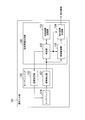
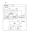
- FIG. 1 shows a configuration example of a mobile terminal device 100 according to the first embodiment.
- a mobile terminal device 100 shown in this figure includes an operation input unit 101, a control unit 102, a display unit 103, and a communication unit 104.
- the operation input unit (operation input device) 101 outputs designated coordinates corresponding to an operation performed by the user on the touch pad.
- the operation input unit 101 includes a touch pad 110, a touch pad interface 120, and an instruction coordinate output unit 130.
- the touch pad (coordinate detection unit) 110 outputs a coordinate detection signal according to a contact state in which the finger is in contact and a close state in which the finger is not in contact.
- a detection method of the touch pad 110 for example, a capacitance method for detecting a capacitance generated between a sensor and a finger is known.
- the touch pad detection method in the present embodiment is not particularly limited.
- the touch pad 110 according to the present embodiment may be combined with the display unit 103 so as to be a part of the touch pad that can operate the image displayed on the display unit 103. What is the display unit 103?
- the mobile terminal device 100 may be provided as an independent operation part.
- the touch pad interface 120 is a part that inputs and outputs signals to and from the touch pad 110.
- the touch pad interface 120 is based on a detection signal output from the touch pad 110, and a contact area where the finger is in contact with the touch pad 110 and a proximity area where the finger is not in contact with the touch pad 110. And detect.
- the touch pad interface 120 changes and sets the sensitivity of the touch pad 110. Thereby, the touch pad 110 switches the sensitivity between the standard sensitivity that outputs a detection signal corresponding to only the contact area and the high sensitivity that outputs a detection signal corresponding to each of the contact area and the proximity area. Is called.
- the designated coordinate output unit 130 determines the designated coordinates based on the information on only the contact area detected by the touch pad interface 120 or the information on the contact area and the proximity area, and outputs the decided designated coordinates.
- the control unit 102 realizes a function as the mobile terminal device 100 by executing control of each unit and various processes in the mobile terminal device 100.
- the control unit 102 can be configured by, for example, a CPU (Central Processing Unit), a main storage device (RAM: Random Access Memory), and an auxiliary storage device (flash memory, hard disk, etc.).
- a CPU Central Processing Unit
- main storage device RAM: Random Access Memory
- auxiliary storage device flash memory, hard disk, etc.
- the display unit 103 displays an image according to the control of the control unit 102.
- a liquid crystal display device can be used as the display unit 103.
- the communication unit 104 is a part for communicating with other devices via a predetermined communication network.
- the communication unit 104 has a function for communicating with another mobile phone via a communication network for a call.
- the communication unit 104 has a function for communicating with other mobile terminal devices on the Internet or a LAN (Local Area Network) via a gateway, for example.
- the mobile terminal device 100 has a short-range wireless communication function such as Bluetooth (registered trademark)
- the communication unit 104 has a communication function corresponding to a predetermined short-range wireless communication method.
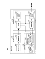
- FIG. 2 shows a configuration example of the operation input unit 101.
- the operation input unit 101 includes a touch pad 110, a touch pad interface 120, and an instruction coordinate output unit 130.
- the touch pad interface 120 includes a region detection unit 121 and a sensitivity setting unit 122.
- the designated coordinate output unit 130 includes a region integration unit 131, a determination unit 132, a determination result storage unit 133, and a designated coordinate determination unit 134.
- the area detection unit 121 Based on the detection signal output from the touch pad 110, the area detection unit 121 includes a contact area where the finger is in contact with the touch pad 110, and an adjacent area where the finger is not in contact with the touch pad 110. Is detected. Note that the area detection unit 121 outputs information indicating the coordinates of the contact area and the coordinates of the proximity area on the touch pad 110 as a detection result.
- the sensitivity setting unit 122 sets the sensitivity of the touch pad 110. As described above, the sensitivity setting unit 122 outputs the detection sensitivity corresponding to only the contact area with respect to the sensitivity of the touch pad 110, and the sensitivity higher than the standard sensitivity and each of the contact area and the proximity area. Sensitivity is set so as to change between high sensitivity that outputs a detection signal according to.
- the standard sensitivity is set, the area detection unit 121 detects only the contact area based on the detection signal of the touch pad 110.
- the area detection unit 121 detects the contact area and the proximity area based on the detection signal of the touch pad 110.
- the sensitivity of the touch pad 110 can be changed, for example, by changing the resolution in the two-dimensional direction of the sensor included in the touch pad 110. That is, at the standard resolution, the sensor of the touch pad 110 outputs a detection signal corresponding to only the contact area where the finger is in contact.
- the sensor of the touch pad 110 is not only a contact region, but a region where the finger is not in contact but is close to the sensor at a distance of, for example, about 10 mm ( That is, it is possible to output a detection signal corresponding to the adjacent region. That is, the sensitivity of the touch pad 110 is increased.
- the sensitivity of the touch pad 110 can be set higher than the standard by reducing the temporal resolution of the sensor of the touch pad 110 below the standard. That is, the scan frequency of the sensor of the touch pad 110 is set lower than the standard. As a result, the touch pad 110 operates so as to output not only the contact area but also a detection signal corresponding to the proximity area.
- the region integration unit 131 integrates the coordinates of the proximity region and the coordinates of the contact region individually detected by the region detection unit 121 when high sensitivity is set for the touch pad 110. To do.
- the area integration unit 131 generates integrated detection area information indicating the coordinates of the proximity area and the coordinates of the contact area as an integration result.
- the region integration unit 131 outputs a standard detection region signal based only on information indicating the coordinates of the contact region output from the touch pad 110 as a detection result.
- the determination unit 132 determines whether or not the proximity area should be used in determining the designated coordinates. In this determination, the determination unit 132 determines whether, for example, the area of the contact region is equal to or greater than a threshold value.
- the case where the area of the contact area is equal to or larger than the threshold corresponds to the case where the finger in contact with the touch pad 110 for operation is the thumb.
- the designated coordinate determination unit 134 uses the coordinate information of the proximity area together with the contact area to determine the designated coordinate. Accordingly, when the area of the contact area is equal to or greater than the threshold value, the determination unit 132 determines that the proximity area should be used in determining the designated coordinates.
- the designated coordinate determination unit 134 uses only the coordinate information of the contact area to determine the designated coordinate. Therefore, when the area of the contact area is less than the threshold, the determination unit 132 determines that the proximity area is not used in determining the designated coordinates.
- the determination result storage unit 133 stores the determination result of the determination unit 132. Specifically, when the determination unit 132 determines that the proximity region should be used, the determination unit 132 stores determination result information indicating the use of the proximity region in the determination result storage unit 133. If the determination unit 132 determines not to use the proximity region, the determination unit 132 stores determination result information indicating that the proximity region is not used in the determination result storage unit 133. In the case of such a configuration, the determination result information stored in the determination result storage unit 133 may be 1-bit information indicating whether the adjacent area is used or not used.
- the designated coordinate determination unit 134 determines the designated coordinates based on either the integrated detection area information or the standard detection area information output from the area integration unit 131.
- the designated coordinates are coordinates designated by a finger on the touch pad 110.
- the instruction coordinate determination unit 134 determines the instruction coordinate based on the detected contact area and the detected proximity area.
- the designated coordinate determination unit 134 determines the designated coordinates based only on the detected contact area.
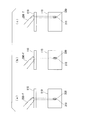
- FIG. 3A, FIG. 3B, and FIG. 3C each show a state in which the touch pad 110 is operated with the index finger 200-f from the side, and at this time, the touch pad 110 The detected area is shown.
- the index finger 200-f moves on the touch pad 110 in the direction of the fingertip side (the right direction on the paper surface) in the order of FIGS. 3 (a), 3 (b), and 3 (c).
- the index finger 200-f itself is relatively thin. For this reason, for example, as shown in FIGS. 3A, 3 ⁇ / b> B, and 3 ⁇ / b> C, the area of the contact region 310 where the belly of the finger contacts on the touch pad 110 is small. Further, in the case of the index finger 200-f, even if the fingertip is moved on the touch pad 110, the index finger 200-f itself is kept standing, so that the fingertip is always stable. There is a tendency to come into contact with 110.
- a position (coordinates) that a user who performs an operation on the touch pad 110 intends to designate on the touch pad 110 is a position corresponding to the fingertip.
- the fingertip of the index finger is always in contact with the touch pad 110. Therefore, in the case of the index finger, the position (coordinates) that the user intends to instruct on the touch pad 110 is almost included in the contact area 310 that is actually detected by the touch pad 110. It is a state. Therefore, in the case of the index finger, the designated coordinates may be determined based on the information on the contact area 310 without using the information on the proximity area.
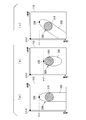
- FIG. 4 (a), 4 (b), and 4 (c), respectively, show a state in which the touch pad 110 is operated with the thumb 200-t from the side, and at this time, the touch pad 110 is The detected area is shown. Further, the thumb 200-t moves on the touch pad 110 in the direction of the fingertip in the order of FIG. 4A, FIG. 4B, and FIG. 4C.
- the thumb 200-t is considerably thicker than the index finger 200-f, and the belly of the finger is considerably wider accordingly. For this reason, as shown in FIG. 4A, FIG. 4B, and FIG. 4C, the area of the contact region 310 where the belly of the thumb 200-t contacts on the touch pad 110 is large.
- the contact area 310 actually detected by the touch pad 110 is detected. Is closer to the root side than the tip of the thumb 200-t. That is, in the case of the thumb 200-t, the position (coordinates) that the user intends to instruct on the touch pad 110 is larger than the contact area 310 that is actually detected by the touch pad 110. It will be in a state that comes off.
- the touch pad 110 is set to high sensitivity, as shown in FIG. 4A, FIG. 4B, and FIG.
- the portion of the thumb 200-t that is close to the top is detected as the proximity region 320.
- the proximity region 320 also includes a portion near the tip of the thumb 200-t. From this, in the case of the thumb, it is more suitable for the user's intention to determine the vicinity of the tip of the thumb 200-t as the designated coordinate 330 using the information of the proximity region 320.
- the determination unit 132 determines whether or not the proximity region 320 should be used for determining the designated coordinates depending on whether the finger operating the touch pad 110 is a thumb or an index finger. That is, when the area of the contact area is less than the threshold, the determination unit 132 determines not to use the proximity area in response to the finger operating the touch pad 110 being the index finger. Further, when the area of the contact region detected by the region detection unit 121 is equal to or larger than the threshold, the determination unit 132 should use the proximity region according to the finger operating the touch pad 110 being the thumb. Is determined.
- the determination unit 132 instructs the sensitivity setting unit 122 to set the touch pad 110 to the standard sensitivity in response to determining that the proximity region is not used.
- the sensitivity setting unit 122 sets the touch pad 110 to the standard sensitivity in response to this instruction.
- the touch pad 110 is set to the standard sensitivity.
- the touch pad 110 to which the standard sensitivity is set detects only the contact area 310 and outputs a detection signal.
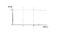
- FIG. 5 shows the relationship between the value of the detection signal (detection value) output from the touch pad 110 to which the standard sensitivity is set and the distance of the finger with respect to the surface of the touch pad 110.
- a detection value of “1.0” is obtained when the distance of the finger to the surface is “0”, but the distance is “0”.
- the detected value is “0”. That is, the touch pad 110 for which the standard sensitivity is set operates so as to output the maximum detection signal only when the finger is in contact with the surface.
- FIG. 6A shows a state in which the finger 200 is in contact with the touch pad 110 from the side surface direction.
- FIG. 6B shows a contact area 310 detected by the touch pad 110 having the standard sensitivity in the state shown in FIG.
- FIG. 6C shows a distribution of detection signals at the coordinate x1 of the touch pad 110 in FIG.
- the touch pad 110 with the standard sensitivity set detects the maximum value “1.0” corresponding to only the coordinates of the contact area 310 with which the finger 200 is in contact.
- a signal is output, and a detection signal having a value of “0” is output for the coordinates of the region other than the contact region 310 where the finger 200 is not in contact.
- the region integration unit 131 receives the detection signal shown in FIG. 6C, detects, for example, a region having coordinates with a detection value of “1.0” as the contact region 310, and displays information indicating the coordinates. Output as standard detection area information.
- the designated coordinate determination unit 134 inputs the standard detection area information and determines the designated coordinates as follows. That is, when the standard sensitivity is set, that is, when it is determined that the proximity area information is not used, the indication coordinate determination unit 134, as shown in FIG. 3, shows the contact indicated by the standard detection area information. The center position in the coordinate range of the area 310 is determined as the designated coordinates 330.
- the determination unit 132 determines that the information on the proximity region should be used, the determination unit 132 instructs the sensitivity setting unit 122 to set the touch pad 110 with high sensitivity.
- the sensitivity setting unit 122 sets the touch pad 110 to high sensitivity in response to this instruction.
- the touch pad 110 is set to high sensitivity.
- FIG. 7 shows the relationship between the value (detection value) of the detection signal output from the touch pad 110 to which high sensitivity is set and the distance of the finger with respect to the surface of the touch pad 110.
- the touch pad 110 set with high sensitivity outputs a detection signal of “1.0” (maximum value) for the contact region 310 where the distance of the finger to the surface is “0”. To do. This is the same as when the standard sensitivity is set.
- the touch pad 110 is “0” up to a certain distance (for example, about 10 mm) even if the distance between the finger and the surface of the touch pad is greater than “0”.
- a detection signal with a larger value is output.
- the touch pad 110 to which high sensitivity is set outputs a detection signal corresponding to the part of the finger located within a certain distance from the pad surface even if the finger is not in contact with the pad surface. That is, the touch pad 110 can detect the part of the finger that is in proximity to the pad surface.
- FIG. 8A shows a state in which the finger 200 is in contact with the touch pad 110 from the side surface direction.
- FIG. 8B shows the contact region 310 and the proximity region 320 detected by the touch pad 110 set with high sensitivity in the state shown in FIG.
- FIG. 8C shows a distribution of detection signals at the coordinate x1 of the touch pad 110 in FIG.
- the touch pad 110 outputs a detection signal of “1.0” (maximum value) corresponding to the coordinates of the contact area 310 with which the finger 200 is in contact.
- the touch pad 110 also outputs a detection signal corresponding to the coordinates of the proximity region 320 corresponding to the portion of the finger 200 that is in close proximity to the pad surface.
- the detection signal corresponding to the coordinates of the proximity region 320 is a signal having a value corresponding to the distance from the pad surface within a range of values less than “1.0” and greater than “0”.
- the region detection unit 121 inputs the detection signal shown in FIG. 8C and, for example, each of the contact region 310 and the proximity region 320 as follows. Is detected.
- the area detection unit 121 inputs a detection value for each coordinate of the sensor on the touch pad 110 as a detection signal. Then, the area detection unit 121 compares the input detection value for each coordinate with a threshold th1 set as shown in FIGS.
- the threshold value th1 is set so as to discriminate between a detection value of “1.0” corresponding to the contact area 310 and a detection value of less than “1.0” corresponding to the proximity area 320.
- the region detection unit 121 detects that the range including the coordinates of the detection value equal to or greater than the threshold th1 is the contact region 310. Further, the region detection unit 121 detects a range including coordinates of detection values that are less than the threshold th1 and greater than “0” as the proximity region 320.
- the region integration unit 131 integrates the coordinate range of the contact region 310 detected by the region detection unit 121 and the coordinate range of the proximity region 320 to generate integrated detection region information, and outputs the integrated detection region information.
- the integrated detection area information is information indicating the coordinate range of the contact area 310 and the coordinate range of the proximity area 320 on the touch pad 110, as schematically shown in FIG.
- the designated coordinate determination unit 134 determines the designated coordinates 330 based on the integrated detection area information in response to the output of the integrated detection area information as described above. A method for determining the designated coordinates 330 based on the integrated detection area information will be described with reference to a first example to a third example.
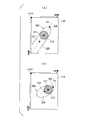
- the coordinates of the touch pad 110 as shown in FIGS. 9A, 9B, and 9C, for example, the coordinates of the position corresponding to the upper left vertex are set to the origin O (0 , 0), the horizontal direction is set as the x axis and the vertical direction is set as the y axis.
- the designated coordinate determination unit 134 of the first example determines the designated coordinates 330 by the following algorithm.
- the designated coordinate determination unit 134 is located at the origin O most of the contact points between the integrated detection region 300 including the contact region 310 and the proximity region 320 indicated by the integrated detection region information and the y coordinate (a line parallel to the x axis). Identify close contacts. Then, the coordinates of the specified contact point are determined as instruction coordinates 330.
- the joint of the thumb extends to contact the touch pad 110, and the thumb is placed on the touch pad 110 with the fingertip facing almost directly above. Indicates the state.
- the vicinity of the fingertip is in the state of being close to the pad surface, it is detected as the proximity region 320, and the contact region 310 is detected in correspondence with the belly portion of the finger in contact with the pad surface.
- the proximity region 320 is detected in correspondence with the fact that the base side of the abdomen of the finger in contact with the pad surface is close to the pad surface without contacting the pad surface.
- the contact point is specified as the contact point closest to the origin O, and determined as the designated coordinate 330.
- the designated coordinates 330 determined in this way is the tip on the fingertip side in the proximity region 320. That is, the indication coordinates 330 correspond to the position of the fingertip of the thumb that is not in contact with the touch pad 110 but is close to the pad surface.
- FIG. 9B shows a state where the thumb is placed on the touch pad 110 with the thumb standing. In this case, the area of the proximity region 320 in the integrated detection region 300 is reduced. In this state, since the fingertip of the thumb contacts the touch pad, the contact area 310 is close to the fingertip side.
- FIG. 9C shows a state where the thumb is slightly inclined with respect to the touch pad 110.
- the instruction coordinates 330 determined in this way are slightly displaced from the tip of the finger, but are positioned so that there is no problem with handling as the tip of the proximity region 320.
- the appropriate designated coordinate 330 is set with an error that does not cause a problem. Can be determined.
- the method for determining the designated coordinate 330 described with reference to FIG. 9 is effective in a case where the movement of the finger with respect to the touch pad 110 is substantially along the y-axis. If the method shown in FIG. 9 is employed under such an aspect, it is possible to determine the designated coordinates that meet the user's intention with a relatively high accuracy even though the processing load is simple and light. However, as described with reference to FIG. 9C, even if the thumb is slightly inclined with respect to the touch pad 110, the designated coordinates can be determined with a small error.
- a designated coordinate determination method as a second example will be described.
- the designated coordinates can be appropriately determined regardless of the direction of the finger applied to the touch pad 110.
- FIG. 10A shows a state in which the thumb is applied in a state where the thumb is inclined obliquely to the right with respect to the touch pad 110.
- the designated coordinate determination unit 134 determines the designated coordinates as follows using the designated coordinate determination method of the second example. To do. First, the designated coordinate determination unit 134 obtains the center coordinates 311 of the contact area 310 and the center coordinates 321 of the proximity area 320 and then sets a straight line Lc that passes through the center coordinates 311 and the center coordinates 321.
- the designated coordinate determination unit 134 obtains one coordinate of the intersection of the outer edge of the integrated detection region 300 including the contact region 310 and the proximity region 320 and the straight line Lc.
- the integrated detection area 300 in FIG. 10A is in a state where a portion of the proximity area 320 corresponding to the base side of the thumb extends to the lower left side of the touch pad 110.
- the designated coordinate determination unit 134 does not regard the part where the detection area reaches the end of the touch pad 110 as the outer edge of the integrated detection area 300. Therefore, the designated coordinate determination unit 134 in this case obtains the tip portion of the proximity region 320 on the fingertip side as the coordinates of the intersection of the outer edge of the integrated detection region 300 and the straight line Lc.
- the designated coordinate determination unit 134 determines the coordinates thus obtained as the designated coordinates 330.
- the designated coordinate 330 determined by the designated coordinate determining method as the second example also corresponds to the position corresponding to the fingertip of the thumb.
- the area of the contact region 310 in the integrated detection region 300 is small by being applied to the touch pad 110 with the thumb standing.
- the fingertip is the upper right end portion of the outer edge of the integrated detection region 300, and the lower left end portion on the opposite side is the side close to the root of the finger.
- the direction of the thumb with respect to the touch pad 110 is slanted to a level close to the horizontal direction.
- the designated coordinate determination unit 134 determines the coordinate closer to the contact area 310 as the designated coordinate 330.
- the instruction coordinate determination unit 134 can accurately determine the instruction coordinates 330 regardless of the direction of the finger with respect to the touch pad 110. Further, the method shown in FIG. 10 is also a process of obtaining an intersection point between the straight line Lc passing through the center coordinates 311 of the contact area 310 and the center coordinates 321 of the proximity area 320 and the outer edge of the integrated detection area 300.
- the processing burden is light.
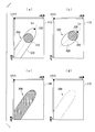
- the designated coordinate determination unit 134 corresponding to the designated coordinate determination method of the third example approximates a coordinate group corresponding to the integrated detection region 300 including the contact region 310 and the proximity region 320 indicated by the integrated detection region information by the least square method.
- an approximate straight line Ln is obtained as shown in FIGS. 11 (a) and 11 (b).
- the designated coordinate determination unit 134 determines the intersection point between the outer edge of the integrated detection region 300 and the approximate straight line Ln as the designated coordinate 330.
- the designated coordinate 330 can be appropriately set regardless of the direction of the finger with respect to the touch pad 110, similarly to the designated coordinate determination method of the second example.
- the designated coordinates 330 can be obtained with sufficiently high accuracy by using the least square method.
- the designated coordinate determination unit 134 uses all coordinates forming the integrated detection region 300 as shown in FIG.
- the designated coordinate determination unit 134 may use, for example, some of the coordinates extracted at regular intervals from all the coordinates that form the integrated detection region 300.
- the designated coordinate determination unit 134 may use the coordinates of the outer edge of the integrated detection region 300 in the least square method, as shown in FIG.
- FIG. 11C and FIG. 11D are compared, the indicated coordinate 330 can be obtained with higher accuracy in FIG. 11C. Further, in FIG. 11D, the processing load required for the calculation for obtaining the designated coordinate 330 is lighter.
- the front end portion in the contact region 310 is determined as the indication coordinate 330.
- the designated coordinates 330 are determined so as to correspond to the position of the fingertip by any of the designated coordinate determination methods of the first example to the third example.
- the position at which the user operating the touch pad 110 is aware that the user is pointing is the fingertip. Therefore, in the present embodiment, the designated coordinates can be determined so as to suit the user's intention.
- the coordinates corresponding to the position of the fingertip are not obtained by estimation, but are obtained by directly using information detected as the proximity region 320. Thereby, regardless of individual differences such as the size of the finger and how the finger is applied to the touch pad 110, the coordinates corresponding to the position of the fingertip of each user's finger can be specified, and appropriate designated coordinates can be determined. .
- the coordinates of the position corresponding to the fingertip in the integrated detection area 300 are detected as the designated coordinates. As described above, this is based on the fact that the designated position on the touchpad intended by the user is generally the tip of the finger. However, depending on the user, the designated coordinates intended by the user may be closer to the belly of the finger than the tip of the finger.
- the designated coordinate determination unit 134 may determine the designated coordinates so as to be closer to the belly of the finger than the tip of the finger.
- the designated coordinate determination unit 134 determines the designated coordinates 330 corresponding to the tip portion of the finger, for example, by any one of the methods shown in FIGS.
- the designated coordinates 330 in this case are provisional.
- the designated coordinate determination unit 134 obtains coordinates located at a predetermined distance between the center coordinate 311 of the contact area 310 and the designated coordinates 330 corresponding to the tip portion of the finger, and thus obtained coordinates. Is determined as the normal designated coordinates 330-1. As an example, the designated coordinate determination unit 134 sets the center coordinates 311 of the contact area 310 as (xc, yt), the designated coordinates 330 corresponding to the tip of the finger as (xt, yt), and the weighting coefficient as p. The normal designated coordinates 330-1 (x, y) is calculated by the calculation for averaging.
- the weighting factor p can be arbitrarily set according to, for example, a user operation. By setting the weighting coefficient p, the user can change the degree to which the designated coordinates are moved to the base side of the finger according to his / her preference and operation feeling, and the operation feeling is improved.
- the determination unit 132 may use a threshold th as a predetermined fixed value.
- the threshold th is set to an appropriate value for each user according to the individual difference in the contact area between the thumb and the index finger with respect to the touch pad 110. It is preferable.
- the operation input unit 101 may change the threshold th as described with reference to FIG.
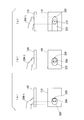
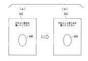
- the touch pad 110 is configured as a touch pad in combination with the display unit 103 will be described as an example.
- the control unit 102 causes the display unit 103 to display a screen for acquiring the area of the contact area 310 of the thumb, as shown in FIG.
- the user places the belly side of the thumb in contact with the mark 400 displayed on this screen.
- the touch pad 110 outputs a detection signal of the contact area detected in the mark 400, and the area detection unit 121 detects the coordinate range of the contact area.
- the determination unit 132 holds information on the coordinate range of the contact area corresponding to the thumb detected by the area detection unit 121.
- control unit 102 causes the display unit 103 to display a screen for acquiring the area of the contact area 310 of the index finger shown in FIG.
- the user puts the ventral side of the index finger on the mark 400 displayed on this screen so as to contact.
- the determination unit 132 holds information on the coordinate range of the contact area corresponding to the index finger detected by the area detection unit 121.
- the determination unit 132 stores the threshold value th calculated as described above and uses it for subsequent determinations. Accordingly, the determination unit 132 determines whether or not the information in the proximity area 320 should be used for determining the designated coordinates in accordance with the size of the user's finger (whether the touch pad 110 is operated by the thumb or the index finger). Can be appropriately determined.
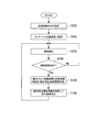
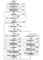
- FIG. 14 shows an example of a processing procedure for determining designated coordinates executed by the operation input unit 101. Note that the processing shown in this figure is the most basic one in the first embodiment, and information on the proximity region 320 is constantly used by fixedly setting high sensitivity for the touch pad 110. The designated coordinates 330 are determined.
- the determination unit 132 determines that the information on the proximity region 320 should be used in response to the designation that the information on the proximity region 320 should be used (step S101). In response to this determination, the determination unit 132 instructs the sensitivity setting unit 122 to set the touch pad 110 to high sensitivity (step S102).
- the area detection unit 121 performs area detection based on the detection signal of the touch pad 110 (step S103), and determines whether or not the contact area 310 is detected as the area detection result (step S104). .
- the region detection unit 121 may determine whether or not there is a coordinate range in which the value (detection value) of the detection signal is the maximum value “1.0”.
- step S104 If the contact area 310 is not detected (step S104—NO), the area detection unit 121 returns to step S103. On the other hand, when the contact area 310 is detected (step S104—YES), the area detection unit 121 detects the proximity area 320 together with the contact area 310 as described above. Therefore, the region integration unit 131 integrates information on the contact region 310 and the proximity region 320 detected by the region detection unit 121 to generate integrated detection region information (step S105).
- the designated coordinate determination unit 134 uses the generated integrated detection area information to determine the designated coordinate 330 (or designated coordinate 330-1), for example, by any of the methods described with reference to FIGS. S106). After finishing the process of step S106, it returns to step S103.
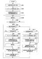
- the operation input unit 101 changes the sensitivity of the touch pad 110 and determines the designated coordinates depending on whether the finger used for the operation of the touch pad 110 is a thumb or an index finger.
- An example of the processing procedure is shown.
- the determination unit 132 determines that the adjacent region is not used unconditionally as an initial determination regardless of the area of the contact region 310 (step S201). Further, the determination unit 132 executes control for setting the standard sensitivity on the touch pad 110 according to the determination result (step S202). In addition, the determination unit 132 stores determination result information indicating proximity region non-use, which is the determination result in step S201, in the determination result storage unit 133 (step S203).
- the region detection unit 121 inputs a detection signal of the touch pad 110 to perform region detection (step S204), and determines whether or not the contact region 310 is detected as a result of the region detection (step S204). S205).
- step S205 If the contact area 310 is not detected (step S205—NO), the area detection unit 121 returns to step S204.
- step S205—YES the determination unit 132 determines whether or not the area of the detected contact area 310 is greater than or equal to the threshold th (step S206).
- the determination that the area of the contact region 310 is equal to or larger than the threshold th corresponds to the determination that the proximity region 320 should be used, and the area of the contact region 310 is less than the threshold th. This determination corresponds to the determination that the proximity region 320 is not used.
- the determination unit 132 When it is determined that the area of the contact region 310 is equal to or greater than the threshold th (the proximity region 320 should be used) (step S206—YES), the determination unit 132 further determines the determination result information stored in the determination result storage unit 133. It is determined whether or not indicates the use of the proximity area (step S207).
- step S207 If the determination result information indicates that the proximity area is used (step S207—YES), the touch pad 110 has already been set to high sensitivity. In this case, therefore, steps S208 to S210 are skipped and the process proceeds to step S211.
- the determination unit 132 performs control to set the touch pad 110 to high sensitivity (step S208).
- the determination unit 132 causes the determination result storage unit 133 to store determination result information indicating the use of the proximity region (step S209).
- the determination unit 132 may rewrite the determination result information, which has so far indicated that the proximity area is not used, with the content indicating the use of the proximity area.
- the area detection unit 121 inputs a detection signal from the touch pad 110 and performs area detection again (step S210). Thereby, the area detection unit 121 detects the coordinate ranges of the contact area 310 and the proximity area 320.
- the region integration unit 131 integrates information on the contact region 310 and the proximity region 320 detected by the region detection unit 121 to generate integrated detection region information (step S211).
- the designated coordinate determination unit 134 determines the designated coordinate 330 (or designated coordinate 330-1) using the generated integrated detection area information (step S212).
- the determination unit 132 When it is determined that the area of the contact region 310 is less than the threshold th (the proximity region 320 is not used) (NO in step S206), the determination unit 132 further determines the determination result stored in the determination result storage unit 133. It is determined whether or not the information indicates that the adjacent area is not used (step S213).
- step S213-YES If the determination result information indicates that the proximity area is not used (step S213-YES), the touch pad 110 has already been set to the standard sensitivity. Therefore, in this case, steps S214 and S215 are skipped and the process proceeds to step S216.
- the touch pad 110 when the determination result information indicates the use of the proximity region (NO in step S213), the touch pad 110 is in a state where high sensitivity is set. Therefore, the determination unit 132 performs control for setting the touch pad 110 to the standard sensitivity (step S214), and rewrites the determination result information stored in the determination result storage unit 133 to content indicating that the proximity area is not used (step S215). . As a result, the touch pad 110 outputs a detection signal corresponding to only the contact area 310, and the area detection unit 121 operates to detect only the coordinate range of the contact area 310.
- the region integration unit 131 generates standard detection region information based only on the information on the contact region 310 detected by the region detection unit 121 (step S216).
- the designated coordinate determination unit 134 uses the generated standard detection area information to determine the center position of the contact area 310 as the designated coordinates 330 as described with reference to FIG. 3 (step S217). After finishing the process of step S212 or step S217, it returns to step S204. Note that the processing shown in FIGS. 14 and 15 may be switched to either one according to the user's setting operation, for example.
- the sensitivity of the touch pad 110 is switched between high sensitivity and standard sensitivity according to the determination as to whether or not the proximity region 320 should be used.
- high sensitivity is fixedly set for the touch pad 110.
- the operation input unit 101 determines the designated coordinates 330 (or designated coordinates 330-1) using the information of the contact area 310 and the proximity area 320. Further, when the operation input unit 101 of the second embodiment determines that the proximity area 320 is not used, the operation input unit 101 determines the designated coordinates 330 (or designated coordinates 330-1) using only the information of the contact area 310. To do.
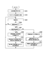
- the flowchart of FIG. 16 shows an example of a processing procedure executed by the operation input unit 101 in the second embodiment to determine the designated coordinate 330.
- the determination unit 132 determines that the proximity region should be used unconditionally as an initial determination (step S301).
- the determination unit 132 executes control for setting the touch pad 110 to high sensitivity (step S302).
- the area detection unit 121 inputs a detection signal from the touch pad 110 and performs area detection (step S303). Since the touch pad 110 is set to high sensitivity, the area detection unit 121 in step S303 detects the contact area 310 and the proximity area 320. And the area
- step S304 If the contact area 310 is not detected (step S304—NO), the area detection unit 121 returns to step S303. On the other hand, when the contact area 310 is detected (YES in step S304), the determination unit 132 determines whether or not the area of the detected contact area 310 is equal to or greater than the threshold th (whether or not the information on the proximity area 320 should be used). (Step S305).
- the region detection unit 121 stores each information of the detected contact region 310 and the proximity region 320. Output (step S306). Therefore, the region integration unit 131 integrates information on the contact region 310 and the proximity region 320 detected by the region detection unit 121 to generate integrated detection region information (step S307).
- the designated coordinate determination unit 134 determines the designated coordinate 330 (or designated coordinate 330-1) using the generated integrated detection area information (step S308).
- the region detection unit 121 detects the detected information on the contact region 310 and the proximity region 320. Of the information, only the information of the contact area 310 is output (step S309). In response to this, the region integration unit 131 generates standard detection region information including only the information on the contact region 310 (step S310). The designated coordinate determination unit 134 determines the designated coordinate 330 using the generated standard detection area information (step S311). After the process of step S308 or step S311 is complete
- FIG. 17 illustrates a configuration example of the mobile terminal device 100 according to the third embodiment.
- the touch pad 110 operates so as to output a detection signal corresponding to only the contact region 310, for example, when the standard sensitivity is constantly set.
- the mobile terminal device 100 of FIG. 17 further includes a proximity region detection unit 140 in the operation input unit 101.
- the proximity area detection unit 140 includes a proximity area detection device 141 and a proximity area detection device interface 142.
- the proximity area detection device 141 detects the proximity area 320.
- the proximity region detection device 141 may employ an optical sensor that detects a finger close to the pad surface of the touch pad 110 by detecting light or infrared light reflected by the finger.
- a liquid crystal display device incorporating a photosensor is known, but such a device can be used as the proximity region detection device 141.
- the proximity region detection device 141 may employ an ultrasonic sensor that detects a finger that is close to the pad surface of the touch pad 110 by detecting an ultrasonic wave reflected by the finger.
- the proximity area detection device interface 142 receives the detection signal of the proximity area detection device 141 and detects the coordinate range of the proximity area 320.
- the designated coordinate output unit 130 determines the designated coordinates using the information on the contact area 310 input from the touch pad interface 120 and the information on the proximity area 320 input from the proximity area detection unit 140, and the determined coordinate coordinates are used. Output.
- FIG. 18 shows a configuration example of the operation input unit 101 in the third embodiment.
- the touch pad interface 120 includes only the region detection unit 121. That is, in the third embodiment, since the standard sensitivity is fixedly set for the touch pad 110, the sensitivity setting unit 122 is omitted accordingly.
- the area detection unit 121 in the third embodiment detects only the contact area 310 based on the detection signal output from the touch pad 110 having the standard sensitivity.
- the proximity area detection device interface 142 includes a device-corresponding proximity area detection unit 142a.
- the device corresponding proximity region detection unit 142a detects the coordinate range of the proximity region 320 based on the detection signal of the proximity region detection device 141.
- the operation of the device-corresponding proximity region detection unit 142a is controlled by the determination unit 132.
- the determination unit 132 determines that the information of the proximity region 320 should be used
- the determination unit 132 controls to turn on the detection operation of the device corresponding proximity region detection unit 142a.
- the region integration unit 131 inputs the information of the contact region 310 detected by the region detection unit 121 and the information of the proximity region 320 detected by the device corresponding proximity region detection unit 142a, and generates integrated detection region information.
- the designated coordinate determination unit 134 determines the designated coordinate 330 (or designated coordinate 330-1) using information on the coordinate range of the contact area 310 and the proximity area 320 indicated by the integrated detection area information.
- the determination unit 132 when determining that the information of the proximity region 320 is not used, the determination unit 132 performs control so that the detection operation of the device corresponding proximity region detection unit 142a is turned off. Thereby, the information of the proximity region 320 is not output from the device corresponding proximity region detection unit 142a. Therefore, the region integration unit 131 generates standard detection region information including only information on the contact region 310 detected by the region detection unit 121. Then, the designated coordinate determination unit 134 determines the designated coordinate 330 using the information of the coordinate range of the contact area 310 indicated by the standard detection area information.
- FIG. 19 illustrates an example of a processing procedure for determining designated coordinates executed by the operation input unit 101 according to the third embodiment.
- the determination unit 132 determines that the proximity region is not used unconditionally regardless of the area of the contact region 310 (step S401). Further, the determination unit 132 turns off the detection operation of the device corresponding proximity region detection unit 142a according to the determination result of step S401 (step S402). Thereby, the information on the proximity region 320 is not output from the device-corresponding proximity region detection unit 142a. In addition, the determination unit 132 stores determination result information indicating proximity region non-use, which is the determination result in step S401, in the determination result storage unit 133 (step S403).
- the region detection unit 121 detects the contact region 310 by inputting the detection signal of the touch pad 110 (step S404).
- the determination unit 132 determines whether or not the determination result information stored in the determination result storage unit 133 indicates the use of the proximity area (step S405).
- the determination result information indicates the use of the proximity area (step S405—YES)
- the detection operation of the device corresponding proximity area detection unit 142a is set to ON. Therefore, the device corresponding proximity region detection unit 142a receives the detection signal of the proximity region detection device 141 and detects the proximity region 320 (step S406).
- the determination result information indicates that the proximity region is not used (step S405—NO)
- the detection operation of the device corresponding proximity region detection unit 142a is set to OFF. Therefore, the device-corresponding proximity region detection unit 142a in this case does not detect the proximity region 320 by skipping step S406.
- the area detection unit 121 determines whether or not the contact area 310 is detected based on the result of the contact area detection in the previous step S404 (step S407).
- the area detection unit 121 returns to step S404.
- the determination unit 132 determines whether the area of the detected contact area 310 is equal to or greater than the threshold th (step S408).
- the determination unit 132 When it is determined that the area of the contact region 310 is equal to or larger than the threshold th (the proximity region 320 should be used) (YES in step S408), the determination unit 132 further determines the determination result information stored in the determination result storage unit 133. It is determined whether or not indicates the use of the proximity area (step S409).
- step S409 When the determination result information indicates the use of the proximity area (step S409—YES), the detection operation of the device corresponding proximity area detection unit 142a is already set to ON. In this case, therefore, steps S410 to S412 are skipped and the process proceeds to step S413.
- the detection operation of the device corresponding proximity area detection unit 142a is set to OFF.
- the determination unit 132 sets the detection operation of the device-corresponding proximity region detection unit 142a to ON (step S410), and rewrites the determination result information stored in the determination result storage unit 133 to the content indicating the use of the proximity region ( Step S411).
- the device corresponding proximity region detecting unit 142a inputs the detection signal of the proximity region detecting device 141, and the proximity region 320 is input. Is detected (step S412).
- the region integration unit 131 inputs the information of the proximity region 320 detected by the device corresponding proximity region detection unit 142a and the information of the contact region 310 detected by the region detection unit 121.
- the region integration unit 131 integrates the information of the contact region 310 and the proximity region 320 input from the region detection unit 121 and the device corresponding proximity region detection unit 142a to generate integrated detection region information (step S413).
- the designated coordinate determining unit 134 determines the designated coordinate 330 (or designated coordinate 330-1) using the generated integrated detection area information (step S414).
- the determination unit 132 When it is determined that the area of the contact region 310 is less than the threshold th (the proximity region 320 is not used) (NO in step S408), the determination unit 132 further determines the determination result stored in the determination result storage unit 133. It is determined whether or not the information indicates that the adjacent area is not used (step S415).
- step S415 If the determination result information indicates that the proximity area is not used (step S415—YES), the detection operation of the device corresponding proximity area detection unit 142a has already been turned off. Therefore, in this case, steps S416 and S417 are skipped and the process proceeds to step S418.
- the detection operation of the device corresponding proximity area detection unit 142a is set to ON. Therefore, the determination unit 132 sets the detection operation of the device-corresponding proximity region detection unit 142a to off (step S416) and rewrites the determination result information stored in the determination result storage unit 133 to the content indicating that the proximity region is not used ( Step S417). As a result, the device-corresponding proximity region detection unit 142a stops the detection operation, so that only the information on the contact region 310 detected by the region detection unit 121 is input to the region integration unit 131.
- the region integration unit 131 generates standard detection region information based only on the information on the contact region 310 input from the region detection unit 121 (step S418).
- the designated coordinate determining unit 134 uses the generated standard detection area information to determine the center position of the contact area 310 as the designated coordinates 330 as described with reference to FIG. 3 (step S419). After finishing the process of step S414 or step S419, it returns to step S404.
- the designated coordinates may be detected in a state where the device-corresponding proximity region detection unit 142a is fixedly turned on according to the flowchart of FIG.
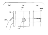
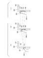
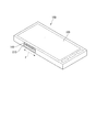
- FIG. 20 illustrates an example of an arrangement mode of the touch pad 110 in the mobile terminal device 100 according to the first embodiment and the second embodiment.
- a mobile terminal device 100 shown in FIG. 20 has a configuration in which an information processing function is combined with a mobile phone called, for example, a smartphone.
- the touch pad 110 is formed in a rectangular shape with a predetermined width and length as shown in the figure, and is provided on the side surface of the housing.
- the user operates the touch pad 110 provided as shown in FIG. 20 to slide along the direction indicated by the arrow F with the thumb of the same left hand while holding the mobile terminal device 100 with the left hand.
- Such an operation on the touch pad 110 depends on an application running on the mobile terminal device 100, but is useful when applied to, for example, screen scrolling or volume operation.
- FIG. 21 shows the state of the thumb 200-t when the slide operation is performed with the thumb 200-t on the touch pad 110 provided as shown in FIG.
- the relationship between the contact area 310 and the proximity area 320 is shown.
- the touch pad 110 is in a state in which high sensitivity is set.
- the user operates to slide the thumb 200-t upward from the bottom of the touch pad 110 in accordance with the order of FIG. 21 (a), FIG. 21 (b), and FIG. 21 (c). .
- the touch pad 110 is in a state of outputting a detection signal corresponding to the contact area 310 in the area near the fingertip of the thumb 200-t as shown in the figure.
- FIG. 21B shows a state in which the fingertip of the thumb 200-t has advanced to near the middle of the touch pad 110 after a certain time has elapsed from the state of FIG.
- the first joint of the thumb 200-t is extended, so that the fingertip of the thumb 200-t is separated from the pad surface of the touch pad 110 and the abdomen of the finger is in contact with the pad surface. It has become.
- the touch pad 110 detects the proximity region 320 corresponding to the fingertip side of the thumb 200-t that is away from the pad surface, and on the lower side thereof, the touch pad 110 touches the pad surface of the thumb 200-t.
- a corresponding contact area 310 is detected.
- the touch pad 110 detects a proximity region 320 corresponding to the root side of the thumb 200-t that is away from the pad surface below the contact region 310.
- FIG. 21C shows a state in which the fingertip of the thumb 200-t has advanced to the upper end side of the touch pad 110 when a certain time has passed since the state of FIG. .
- the fingertip of the thumb 200-t warps upward (to the left in the drawing) and separates from the pad surface of the touch pad 110, and the abdomen of the base side finger is in contact with the pad surface.
- the touch pad 110 detects a proximity region 320 corresponding to the fingertip side of the thumb 200-t that is away from the pad surface, and a portion of the lower side that is in contact with the belly of the finger of the thumb 200-t.
- the contact area 310 corresponding to is detected.
- the touch pad 110 detects the proximity region 320 corresponding to the root side of the thumb 200-t that is away from the pad surface below the contact region 310.
- the designated coordinate 330 is used to move the thumb 200-t upward in the fingertip, as can be understood from FIG. It only moves to the middle of the touch pad 110 without following.
- the user slides the thumb 200-t of the same left hand on the touch pad 110 in a state where the user holds the mobile terminal device 100 with the left hand.
- the left hand itself cannot be moved in the sliding direction, and the sliding operation is performed by bending and extending the joint of the thumb 200-t. Therefore, the warp on the fingertip side as shown in FIG. Is prone to occur.
- the mobile terminal device 100 of the present embodiment includes the operation input unit 101 described so far, as shown in FIG. 21, the designated coordinates 330 are always at a position corresponding to the fingertip of the thumb 200-t. Become. This makes it possible to obtain the movement of the designated coordinates as intended by the user.
- FIG. 22 illustrates an example of an arrangement mode of the touch pad 110 in the mobile terminal device 100 according to the third embodiment.
- the touch pad 110 in the portable terminal device 100 shown in this figure is formed in a rectangular shape as in FIG.
- a proximity region detection device 141 is provided so as to be aligned with the touch pad 110 along the direction of the arrow F.
- FIG. 22 shows an example in which the touch pad 110 and the proximity area detection device 141 are arranged side by side along the plane direction, including the intention to clarify the existence of the proximity area detection device 141.
- the touch pad 110 and the proximity region detection device 141 may be arranged to overlap each other.
- the operation input unit 101 of this embodiment is applied to the mobile terminal device 100.
- the operation input unit 101 can be applied to devices other than the mobile terminal device such as a remote controller. .
- the touch pad 110 is operated with the index finger and the case where it is operated with the thumb.
- the touch pad 110 may be operated with, for example, the middle finger. In this way, even if it is operated with one of the fingers other than the thumb, such as the middle finger, ring finger, little finger, etc., it is determined that these fingers are operated with the index finger because they are thin, the same as with the index finger Since the designated coordinates 330 are determined, there is no particular inconvenience.
- a program for realizing the functions of the respective units in FIGS. 2 and 18 is recorded on a computer-readable recording medium, and the program recorded on the recording medium is read into a computer system and executed. Coordinates may be determined.
- the “computer system” includes an OS and hardware such as peripheral devices.
- the “computer system” includes a homepage providing environment (or display environment) if a WWW system is used.
- the “computer-readable recording medium” refers to a storage device such as a flexible medium, a magneto-optical disk, a portable medium such as a ROM or a CD-ROM, and a hard disk incorporated in a computer system.
- the “computer-readable recording medium” refers to a volatile memory (RAM) in a computer system that becomes a server or a client when a program is transmitted via a network such as the Internet or a communication line such as a telephone line.
- RAM volatile memory
- the program may be a program for realizing a part of the functions described above, and may be a program capable of realizing the functions described above in combination with a program already recorded in a computer system.
- the present invention can be applied to portable devices such as smartphones and tablets.
- DESCRIPTION OF SYMBOLS 100 Portable terminal device 101 Operation input part 102 Control part 103 Display part 104 Communication part 110 Touchpad 120 Touchpad interface 121 Area detection part 122 Sensitivity setting part 130 Instruction coordinate output part 131 Area integration part 132 Determination part 133 Determination result memory
Abstract
A touchpad outputs a detection signal corresponding to a contact state in which a finger makes contact and a close approach state in which a finger makes a close approach without making contact. On the basis of the detection signal of the touchpad, an operation input device detects a contact region in the touchpad whereupon the finger makes contact, and a close approach region in the touchpad whereupon the finger makes the close approach without making contact. Then, the operation input device establishes instruction coordinates on the basis of the detected contact region and the detected close approach region.
Description
本発明は、操作入力装置、操作入力方法およびプログラムに関する。
本願は、2012年4月20日に、日本に出願された特願2012-096643号に基づき優先権を主張し、その内容をここに援用する。 The present invention relates to an operation input device, an operation input method, and a program.
This application claims priority based on Japanese Patent Application No. 2012-096643 filed in Japan on April 20, 2012, the contents of which are incorporated herein by reference.
近年、例えばスマートフォンやタブレットなどをはじめとする携帯型の機器における操作デバイスとしてタッチパッドが広く採用されている。タッチパッドは、ユーザがポインタである指を接触させて操作を行うことにより座標を指示することのできるポインティングデバイスである。
In recent years, touch pads have been widely adopted as operation devices in portable devices such as smartphones and tablets. The touch pad is a pointing device that allows a user to specify coordinates by touching a finger as a pointer and performing an operation.
しかし、ユーザがタッチパッドに対して操作を行ったときの指の状態によっては、ユーザが意図した操作と、実際にタッチパッドにより検出される指示座標が一致しない場合がある。
具体例として、親指を手首側から指先側へ突き出すように動かして操作した場合、操作をはじめたときには、親指の先がタッチパッドに接触している。この状態から親指が指先側に進んでいくのに応じて、親指の先が上側に反っていくことでタッチパッドの上から離れ、親指の腹の部分がタッチパッドに接触するようになる。そして、さらに親指が指先側に進んでいくのに応じて、親指の先の反りがさらに大きくなって、タッチパッドと接触する親指の腹の部分は、さらに親指の根本のほう近づくような状態となる。 However, depending on the state of the finger when the user performs an operation on the touch pad, the operation intended by the user may not match the designated coordinates actually detected by the touch pad.
As a specific example, when the operation is performed by moving the thumb so as to protrude from the wrist side to the fingertip side, the tip of the thumb is in contact with the touch pad when the operation is started. As the thumb advances to the fingertip side from this state, the tip of the thumb is warped upward, so that it is separated from the top of the touch pad, and the belly portion of the thumb comes into contact with the touch pad. Then, as the thumb further advances toward the fingertip side, the warping of the thumb tip further increases, and the belly portion of the thumb that comes into contact with the touchpad further approaches the base of the thumb. Become.
このように親指を動かしているとき、ユーザは指先が指示座標に対応しているイメージを持っている。しかし、この操作のとき、タッチパッドと親指との実際の接触部分は、親指の指先からその腹の根本側に移動していくものであり、タッチパッドにて検出される指示座標もこれに対応したものとなる。例えば、このように、親指で操作しているときには、ユーザが意図している操作と、タッチパッドが実際に検出する指示座標との間でずれが生じやすい。
When the thumb is moved in this way, the user has an image in which the fingertip corresponds to the designated coordinates. However, during this operation, the actual contact area between the touchpad and thumb moves from the fingertip of the thumb toward the base of the belly, and the indicated coordinates detected by the touchpad also correspond to this. Will be. For example, in this way, when operating with the thumb, a shift is likely to occur between the operation intended by the user and the designated coordinates actually detected by the touchpad.
そこで、次のような入力装置が知られている。つまり、この入力装置は、タッチパッドの接触情報に基づき接触領域の上下方向の接触幅Dを算出し、接触領域の中心座標yを算出し、さらに接触幅Dと所定の補正パラメータNとを用いて補正量D/Nを算出する。そして、この入力装置は、接触領域が移動しているときには、補正座標Y=y+D/Nを利用して接触点の移動量を算出し、接触領域が停止しているときは、接触領域の中心座標によって移動量を算出するというものである(例えば、特許文献1参照)。
Therefore, the following input devices are known. That is, the input device calculates the contact width D in the vertical direction of the contact area based on the touch pad contact information, calculates the center coordinate y of the contact area, and further uses the contact width D and the predetermined correction parameter N. To calculate the correction amount D / N. The input device calculates the amount of movement of the contact point using the correction coordinate Y = y + D / N when the contact area is moving, and the center of the contact area when the contact area is stopped. The amount of movement is calculated from the coordinates (see, for example, Patent Document 1).
ここで、指の大きさや形状はユーザごとに異なる。また、タッチパッドを操作する際の指の押し当て方や動かし方などもユーザごとに異なる。これに伴い、タッチパッドを操作しているときの指の反り具合や、タッチパッドと接触する指の腹の位置などをはじめとして、タッチパッドに対する指の接触状態もユーザごとに異なることになる。
Here, the size and shape of the finger varies from user to user. In addition, how to press and move a finger when operating the touch pad is different for each user. Along with this, the finger contact state with respect to the touch pad varies from user to user, including the degree of warping of the finger when operating the touch pad and the position of the belly of the finger in contact with the touch pad.
しかし、特許文献1に記載の入力装置は、所定値による補正パラメータを用いた演算によってタッチパッドと親指の接触点の移動量を算出している。これは、タッチパッドの指示座標を推定により求めているということを意味している。このように推定により指示座標を求める構成では、タッチパッドに対する指の接触状態についてのユーザごとの相違に対応して、そのユーザの意図に応じた座標を適切に指示することが難しい場合がある。
However, the input device described in Patent Document 1 calculates the amount of movement of the contact point between the touch pad and the thumb by calculation using a correction parameter based on a predetermined value. This means that the indicated coordinates of the touch pad are obtained by estimation. In such a configuration in which the designated coordinates are obtained by estimation, it may be difficult to appropriately designate the coordinates according to the user's intention in response to the difference between the users regarding the touch state of the finger with respect to the touch pad.
本発明の一態様としての操作入力装置は、指が接触している接触状態と前記指が接触せずに近接している近接状態とに応じた座標の検出信号を出力する座標検出部と、前記検出信号に基づいて、前記座標検出部において前記指が接触している接触領域と、前記座標検出部において前記指が接触せずに近接している近接領域とを検出する領域検出部と、検出された前記接触領域と検出された前記近接領域とに基づいて、前記座標検出部上の指により指示される指示座標を決定する指示座標決定部とを備える。
An operation input device according to an aspect of the present invention includes a coordinate detection unit that outputs a detection signal of coordinates according to a contact state in which a finger is in contact and a proximity state in which the finger is not in contact with each other, Based on the detection signal, a region detection unit that detects a contact region in which the finger is in contact with the coordinate detection unit and a proximity region in which the finger is not in contact with the coordinate detection unit; An instruction coordinate determination unit that determines an instruction coordinate indicated by a finger on the coordinate detection unit based on the detected contact area and the detected proximity area.
また、前記操作入力装置は、検出された前記接触領域の面積に基づいて、前記指示座標の決定にあたり前記近接領域を利用すべきか否かを判定する判定部をさらに備えてもよい。前記指示座標決定部は、前記近接領域を利用すべきと判定された場合には、前記検出された接触領域と前記検出された前記近接領域とに基づいて前記指示座標を決定し、前記近接領域を利用しないと判定された場合には、前記検出された接触領域のみに基づいて前記指示座標を決定する。
In addition, the operation input device may further include a determination unit that determines whether or not the proximity region should be used in determining the designated coordinates based on the detected area of the contact region. When it is determined that the proximity area should be used, the designated coordinate determination unit determines the designated coordinates based on the detected contact area and the detected proximity area, and the proximity area When it is determined not to use, the designated coordinates are determined based only on the detected contact area.
また、前記操作入力装置は、前記近接領域を利用すべきと判定された場合には、前記接触状態と前記近接状態とに応じた検出信号を前記座標検出部が出力し、前記近接領域を利用しないと判定された場合には、前記接触状態のみに応じた検出信号を前記座標検出部が出力するように、前記座標検出部の感度を設定する感度設定部をさらに備えてもよい。
In addition, when the operation input device determines that the proximity area should be used, the coordinate detection unit outputs a detection signal corresponding to the contact state and the proximity state, and uses the proximity area. If it is determined not to be, a sensitivity setting unit may be further provided to set the sensitivity of the coordinate detection unit so that the coordinate detection unit outputs a detection signal corresponding to only the contact state.
また、前記操作入力装置において、前記指示座標決定部は、前記近接領域を利用すべきと判定された場合には、前記検出された接触領域と前記検出された前記近接領域とから成る統合検出領域において指先に対応する座標を前記指示座標として決定するように構成されていてもよい。
Further, in the operation input device, when it is determined that the proximity area should be used, the designated coordinate determination unit includes an integrated detection area including the detected contact area and the detected proximity area. The coordinates corresponding to the fingertip may be determined as the designated coordinates.
また、前記操作入力装置において、前記指示座標決定部は、前記近接領域を利用しないと判定された場合には、前記検出された接触領域の中心座標を前記指示座標として決定するように構成されていてもよい。
In the operation input device, the designated coordinate determination unit is configured to determine the center coordinate of the detected contact area as the designated coordinate when it is determined not to use the proximity area. May be.
また、前記操作入力装置において、前記判定部は、前記近接領域を利用すべきか否かの判定のために前記接触領域の面積と比較する閾値を、前記座標検出部に親指が接触する面積と、前記座標検出部に前記親指以外のうちのいずれかの指が接触する面積とに基づいて設定するように構成されていてもよい。
Further, in the operation input device, the determination unit compares a threshold to be compared with the area of the contact region for determining whether or not the proximity region should be used, an area where the thumb contacts the coordinate detection unit, The coordinate detection unit may be configured to be set based on an area in contact with any finger other than the thumb.
また、前記操作入力装置は、前記近接領域を検出する近接領域検出部をさらに備えてもよい。前記領域検出部は、前記座標検出部の検出信号に基づいて前記接触領域のみを検出し、前記指示座標決定部は、前記領域検出部により検出された前記接触領域と、前記近接領域検出部により検出された前記近接領域とに基づいて前記指示座標を決定する。
Further, the operation input device may further include a proximity area detection unit that detects the proximity area. The region detection unit detects only the contact region based on a detection signal of the coordinate detection unit, and the designated coordinate determination unit includes the contact region detected by the region detection unit and the proximity region detection unit. The indicated coordinates are determined based on the detected proximity area.
また、本発明の他の一態様としての操作入力方法は、指が接触している接触状態と前記指が接触せずに近接している近接状態とに応じて座標検出部が出力する座標の検出信号に基づいて、前記座標検出部において前記指が接触している接触領域と、前記座標検出部において前記指が接触せずに近接している近接領域とを検出する領域検出ステップと、検出された前記接触領域と検出された前記近接領域とに基づいて、前記座標検出部上の指により指示される指示座標を決定する指示座標決定ステップとを備える。
According to another aspect of the present invention, there is provided an operation input method in which coordinates output by a coordinate detection unit are output according to a contact state in which a finger is in contact and a proximity state in which the finger is not in contact. Based on a detection signal, an area detection step of detecting a contact area where the finger is in contact with the coordinate detection section and a proximity area where the finger is not in contact with the coordinate detection section, and detection And a designated coordinate determining step for determining designated coordinates designated by a finger on the coordinate detection unit based on the contact area and the detected proximity area.
また、本発明の他の一態様としてのプログラムは、コンピュータに、指が接触している接触状態と前記指が接触せずに近接している近接状態とに応じて座標検出部が出力する座標の検出信号に基づいて、前記座標検出部において前記指が接触している接触領域と、前記座標検出部において前記指が接触せずに近接している近接領域とを検出する領域検出ステップ、検出された前記接触領域と検出された前記近接領域とに基づいて、前記座標検出部上の指により指示される指示座標を決定する指示座標決定ステップを実行させる。
In addition, the program as another aspect of the present invention is a program in which coordinates output by the coordinate detection unit according to a contact state in which a finger is in contact with and a proximity state in which the finger is not in contact with the computer are output. An area detection step for detecting a contact area where the finger is in contact with the coordinate detection unit and a proximity area where the finger is not in contact with the coordinate detection unit based on the detection signal Based on the touched area and the detected proximity area, an instruction coordinate determination step for determining an instruction coordinate specified by a finger on the coordinate detection unit is executed.
以上説明したように、本発明の態様によれば、タッチパッドに対する指の接触状態についてのユーザごとの相違に係わらず、ユーザの意図に応じた適切な座標を指示できるように成るという効果が得られる。
As described above, according to the aspect of the present invention, it is possible to indicate an appropriate coordinate according to the user's intention regardless of the difference in the contact state of the finger with respect to the touch pad for each user. It is done.
<第1の実施形態>
[携帯端末装置の構成]
図1は、第1の実施形態における携帯端末装置100の構成例を示している。
この図に示す携帯端末装置100は、操作入力部101、制御部102、表示部103および通信部104を備える。 <First Embodiment>
[Configuration of mobile terminal device]
FIG. 1 shows a configuration example of a mobileterminal device 100 according to the first embodiment.
A mobileterminal device 100 shown in this figure includes an operation input unit 101, a control unit 102, a display unit 103, and a communication unit 104.
[携帯端末装置の構成]
図1は、第1の実施形態における携帯端末装置100の構成例を示している。
この図に示す携帯端末装置100は、操作入力部101、制御部102、表示部103および通信部104を備える。 <First Embodiment>
[Configuration of mobile terminal device]
FIG. 1 shows a configuration example of a mobile
A mobile
操作入力部(操作入力装置)101は、ユーザがタッチパッドに対して行った操作に応じた指示座標を出力する。このために、操作入力部101は、タッチパッド110、タッチパッドインターフェース120および指示座標出力部130を備える。
The operation input unit (operation input device) 101 outputs designated coordinates corresponding to an operation performed by the user on the touch pad. For this purpose, the operation input unit 101 includes a touch pad 110, a touch pad interface 120, and an instruction coordinate output unit 130.
タッチパッド(座標検出部)110は、指が接触している接触状態と指が接触せずに近接している近接状態とに応じた座標の検出信号を出力する。
なお、タッチパッド110の検出方式として、例えば1つには、センサと指との間に発生する静電容量を検出する静電容量方式が知られている。しかし、本実施形態におけるタッチパッドの検出方式については、特に限定されるものではない。
また、本実施形態におけるタッチパッド110は、表示部103と組み合わせられることで、表示部103に表示された画像に対する操作が可能なタッチパッドの一部とされてもよいし、表示部103とは独立した操作部位として携帯端末装置100に設けられてもよい。 The touch pad (coordinate detection unit) 110 outputs a coordinate detection signal according to a contact state in which the finger is in contact and a close state in which the finger is not in contact.
In addition, as a detection method of thetouch pad 110, for example, a capacitance method for detecting a capacitance generated between a sensor and a finger is known. However, the touch pad detection method in the present embodiment is not particularly limited.
In addition, thetouch pad 110 according to the present embodiment may be combined with the display unit 103 so as to be a part of the touch pad that can operate the image displayed on the display unit 103. What is the display unit 103? The mobile terminal device 100 may be provided as an independent operation part.
なお、タッチパッド110の検出方式として、例えば1つには、センサと指との間に発生する静電容量を検出する静電容量方式が知られている。しかし、本実施形態におけるタッチパッドの検出方式については、特に限定されるものではない。
また、本実施形態におけるタッチパッド110は、表示部103と組み合わせられることで、表示部103に表示された画像に対する操作が可能なタッチパッドの一部とされてもよいし、表示部103とは独立した操作部位として携帯端末装置100に設けられてもよい。 The touch pad (coordinate detection unit) 110 outputs a coordinate detection signal according to a contact state in which the finger is in contact and a close state in which the finger is not in contact.
In addition, as a detection method of the
In addition, the
タッチパッドインターフェース120は、タッチパッド110に対する信号の入出力を行う部位である。
タッチパッドインターフェース120は、タッチパッド110から出力される検出信号に基づいて、タッチパッド110において指が接触している接触領域と、タッチパッド110において前記指が接触せずに近接している近接領域とを検出する。また、タッチパッドインターフェース120は、タッチパッド110の感度を変更設定する。これにより、タッチパッド110は、接触領域のみに応じた検出信号を出力する標準感度と、接触領域と近接領域とのそれぞれに応じた検出信号を出力する高感度との間で感度の切り替えが行われる。 Thetouch pad interface 120 is a part that inputs and outputs signals to and from the touch pad 110.
Thetouch pad interface 120 is based on a detection signal output from the touch pad 110, and a contact area where the finger is in contact with the touch pad 110 and a proximity area where the finger is not in contact with the touch pad 110. And detect. The touch pad interface 120 changes and sets the sensitivity of the touch pad 110. Thereby, the touch pad 110 switches the sensitivity between the standard sensitivity that outputs a detection signal corresponding to only the contact area and the high sensitivity that outputs a detection signal corresponding to each of the contact area and the proximity area. Is called.
タッチパッドインターフェース120は、タッチパッド110から出力される検出信号に基づいて、タッチパッド110において指が接触している接触領域と、タッチパッド110において前記指が接触せずに近接している近接領域とを検出する。また、タッチパッドインターフェース120は、タッチパッド110の感度を変更設定する。これにより、タッチパッド110は、接触領域のみに応じた検出信号を出力する標準感度と、接触領域と近接領域とのそれぞれに応じた検出信号を出力する高感度との間で感度の切り替えが行われる。 The
The
指示座標出力部130は、タッチパッドインターフェース120により検出された接触領域のみの情報、または、接触領域と近接領域の情報に基づいて指示座標を決定し、決定した指示座標を出力する。
The designated coordinate output unit 130 determines the designated coordinates based on the information on only the contact area detected by the touch pad interface 120 or the information on the contact area and the proximity area, and outputs the decided designated coordinates.
制御部102は、携帯端末装置100における各部の制御および各種処理を実行することで、携帯端末装置100としての機能を実現する。なお、制御部102は、例えばCPU(Central Processing Unit)、主記憶装置(RAM:Random Access Memory)、補助記憶装置(フラッシュメモリ、ハードディスクなど)により構成することができる。
The control unit 102 realizes a function as the mobile terminal device 100 by executing control of each unit and various processes in the mobile terminal device 100. The control unit 102 can be configured by, for example, a CPU (Central Processing Unit), a main storage device (RAM: Random Access Memory), and an auxiliary storage device (flash memory, hard disk, etc.).
表示部103は、制御部102の制御に応じて画像を表示する。表示部103には、例えば液晶ディスプレイデバイスなどを使用することができる。
The display unit 103 displays an image according to the control of the control unit 102. As the display unit 103, for example, a liquid crystal display device can be used.
通信部104は、所定の通信網経由で他の装置などと通信するための部位である。一例として、携帯端末装置100が携帯電話である場合、通信部104は、通話のための通信網を経由で他の携帯電話と通信するための機能を有する。また、携帯端末装置100がネットワーク通信機能を有する場合、通信部104は、例えばゲートウェイなどを経由してインターネットやLAN(Local Area Network)上の他の携帯端末装置などと通信するための機能を有する。また、携帯端末装置100が例えばブルートゥース(登録商標)などの近距離無線通信機能を有している場合には、通信部104は、所定の近距離無線通信方式に対応した通信機能を有する。
The communication unit 104 is a part for communicating with other devices via a predetermined communication network. As an example, when the mobile terminal device 100 is a mobile phone, the communication unit 104 has a function for communicating with another mobile phone via a communication network for a call. When the mobile terminal device 100 has a network communication function, the communication unit 104 has a function for communicating with other mobile terminal devices on the Internet or a LAN (Local Area Network) via a gateway, for example. . In addition, when the mobile terminal device 100 has a short-range wireless communication function such as Bluetooth (registered trademark), the communication unit 104 has a communication function corresponding to a predetermined short-range wireless communication method.
[操作入力部の構成]
図2は、操作入力部101の構成例を示している。図1にも示したように、操作入力部101は、タッチパッド110、タッチパッドインターフェース120および指示座標出力部130を備える。
そのうえで、タッチパッドインターフェース120は、領域検出部121と感度設定部122を備える。また、指示座標出力部130は、領域統合部131、判定部132、判定結果記憶部133および指示座標決定部134を備える。 [Configuration of operation input section]
FIG. 2 shows a configuration example of theoperation input unit 101. As shown in FIG. 1, the operation input unit 101 includes a touch pad 110, a touch pad interface 120, and an instruction coordinate output unit 130.
In addition, thetouch pad interface 120 includes a region detection unit 121 and a sensitivity setting unit 122. The designated coordinate output unit 130 includes a region integration unit 131, a determination unit 132, a determination result storage unit 133, and a designated coordinate determination unit 134.
図2は、操作入力部101の構成例を示している。図1にも示したように、操作入力部101は、タッチパッド110、タッチパッドインターフェース120および指示座標出力部130を備える。
そのうえで、タッチパッドインターフェース120は、領域検出部121と感度設定部122を備える。また、指示座標出力部130は、領域統合部131、判定部132、判定結果記憶部133および指示座標決定部134を備える。 [Configuration of operation input section]
FIG. 2 shows a configuration example of the
In addition, the
領域検出部121は、タッチパッド110から出力される検出信号に基づいて、タッチパッド110において指が接触している接触領域と、タッチパッド110において指が接触せずに近接している近接領域とを検出する。なお、領域検出部121は、検出結果として、タッチパッド110における接触領域の座標と近接領域の座標を示す情報を出力する。
Based on the detection signal output from the touch pad 110, the area detection unit 121 includes a contact area where the finger is in contact with the touch pad 110, and an adjacent area where the finger is not in contact with the touch pad 110. Is detected. Note that the area detection unit 121 outputs information indicating the coordinates of the contact area and the coordinates of the proximity area on the touch pad 110 as a detection result.
感度設定部122は、タッチパッド110の感度を設定する。前述のように、感度設定部122は、タッチパッド110の感度について、接触領域のみに応じた検出信号を出力する標準感度と、標準感度よりも高い感度であって接触領域と近接領域とのそれぞれに応じた検出信号を出力する高感度との間で変更するように感度を設定する。
標準感度が設定されている場合、領域検出部121は、タッチパッド110の検出信号に基づいて接触領域のみを検出する。高感度が設定されている場合、領域検出部121は、タッチパッド110の検出信号に基づいて接触領域と近接領域とを検出する。 Thesensitivity setting unit 122 sets the sensitivity of the touch pad 110. As described above, the sensitivity setting unit 122 outputs the detection sensitivity corresponding to only the contact area with respect to the sensitivity of the touch pad 110, and the sensitivity higher than the standard sensitivity and each of the contact area and the proximity area. Sensitivity is set so as to change between high sensitivity that outputs a detection signal according to.
When the standard sensitivity is set, thearea detection unit 121 detects only the contact area based on the detection signal of the touch pad 110. When the high sensitivity is set, the area detection unit 121 detects the contact area and the proximity area based on the detection signal of the touch pad 110.
標準感度が設定されている場合、領域検出部121は、タッチパッド110の検出信号に基づいて接触領域のみを検出する。高感度が設定されている場合、領域検出部121は、タッチパッド110の検出信号に基づいて接触領域と近接領域とを検出する。 The
When the standard sensitivity is set, the
また、具体的に、タッチパッド110の感度の変更は、例えば、タッチパッド110が備えるセンサの二次元方向における分解能を変更することにより実現できる。つまり、標準の分解能では、タッチパッド110のセンサは、指が接触している接触領域のみに応じた検出信号を出力する。これに対して、分解能を標準よりも低くすることで、タッチパッド110のセンサは、接触領域だけではなく、指が接触していないが例えば10mm程度までの距離でセンサに近接している領域(すなわち、近接領域である)に応じた検出信号も出力可能になる。つまり、タッチパッド110の感度が高くなる。
また、タッチパッド110のセンサの時間的分解能を標準よりも低下させることによっても、タッチパッド110に標準より高い感度を設定できる。つまり、タッチパッド110のセンサのスキャン周波数を標準よりも低く設定する。これにより、タッチパッド110は、接触領域だけではなく近接領域に応じた検出信号も出力するように動作する。 Further, specifically, the sensitivity of thetouch pad 110 can be changed, for example, by changing the resolution in the two-dimensional direction of the sensor included in the touch pad 110. That is, at the standard resolution, the sensor of the touch pad 110 outputs a detection signal corresponding to only the contact area where the finger is in contact. On the other hand, by making the resolution lower than the standard, the sensor of the touch pad 110 is not only a contact region, but a region where the finger is not in contact but is close to the sensor at a distance of, for example, about 10 mm ( That is, it is possible to output a detection signal corresponding to the adjacent region. That is, the sensitivity of the touch pad 110 is increased.
Also, the sensitivity of thetouch pad 110 can be set higher than the standard by reducing the temporal resolution of the sensor of the touch pad 110 below the standard. That is, the scan frequency of the sensor of the touch pad 110 is set lower than the standard. As a result, the touch pad 110 operates so as to output not only the contact area but also a detection signal corresponding to the proximity area.
また、タッチパッド110のセンサの時間的分解能を標準よりも低下させることによっても、タッチパッド110に標準より高い感度を設定できる。つまり、タッチパッド110のセンサのスキャン周波数を標準よりも低く設定する。これにより、タッチパッド110は、接触領域だけではなく近接領域に応じた検出信号も出力するように動作する。 Further, specifically, the sensitivity of the
Also, the sensitivity of the
また、指示座標出力部130において、領域統合部131は、タッチパッド110について高感度が設定されている場合に、領域検出部121により個別に検出された近接領域の座標と接触領域の座標を統合する。領域統合部131は、統合結果として、近接領域の座標と接触領域の座標が示される統合検出領域情報を生成する。
また、領域統合部131は、タッチパッド110について標準感度が設定されている場合には、タッチパッド110から出力された接触領域の座標を示す情報のみによる標準検出領域信号を検出結果として出力する。 In the designated coordinateoutput unit 130, the region integration unit 131 integrates the coordinates of the proximity region and the coordinates of the contact region individually detected by the region detection unit 121 when high sensitivity is set for the touch pad 110. To do. The area integration unit 131 generates integrated detection area information indicating the coordinates of the proximity area and the coordinates of the contact area as an integration result.
In addition, when the standard sensitivity is set for thetouch pad 110, the region integration unit 131 outputs a standard detection region signal based only on information indicating the coordinates of the contact region output from the touch pad 110 as a detection result.
また、領域統合部131は、タッチパッド110について標準感度が設定されている場合には、タッチパッド110から出力された接触領域の座標を示す情報のみによる標準検出領域信号を検出結果として出力する。 In the designated coordinate
In addition, when the standard sensitivity is set for the
判定部132は、領域検出部121により検出された接触領域の面積に基づいて、指示座標の決定にあたり近接領域を利用すべきか否かを判定する。
この判定にあたり、判定部132は、例えば接触領域の面積が閾値以上であるか否かについて判定する。 Based on the area of the contact area detected by thearea detection unit 121, the determination unit 132 determines whether or not the proximity area should be used in determining the designated coordinates.
In this determination, thedetermination unit 132 determines whether, for example, the area of the contact region is equal to or greater than a threshold value.
この判定にあたり、判定部132は、例えば接触領域の面積が閾値以上であるか否かについて判定する。 Based on the area of the contact area detected by the
In this determination, the
本実施形態において、接触領域の面積が閾値以上である場合とは、操作のためにタッチパッド110に接触している指が親指である場合に相当する。そして、親指である場合、指示座標決定部134は、指示座標の決定には接触領域とともに近接領域の座標の情報を利用する。そこで、判定部132は、接触領域の面積が閾値以上である場合には、指示座標の決定にあたり近接領域を利用すべきと判定する。
In the present embodiment, the case where the area of the contact area is equal to or larger than the threshold corresponds to the case where the finger in contact with the touch pad 110 for operation is the thumb. In the case of the thumb, the designated coordinate determination unit 134 uses the coordinate information of the proximity area together with the contact area to determine the designated coordinate. Accordingly, when the area of the contact area is equal to or greater than the threshold value, the determination unit 132 determines that the proximity area should be used in determining the designated coordinates.
一方、接触領域の面積が閾値未満である場合は、操作のためにタッチパッド110に接触している指が人差し指である場合に相当する。人差し指の場合、指示座標決定部134は、指示座標の決定には接触領域の座標の情報のみを利用する。そこで、判定部132は、接触領域の面積が閾値未満である場合には、指示座標の決定にあたり近接領域を利用しないと判定する。
On the other hand, when the area of the contact area is less than the threshold value, it corresponds to the case where the finger in contact with the touch pad 110 for the operation is an index finger. In the case of the index finger, the designated coordinate determination unit 134 uses only the coordinate information of the contact area to determine the designated coordinate. Therefore, when the area of the contact area is less than the threshold, the determination unit 132 determines that the proximity area is not used in determining the designated coordinates.
判定結果記憶部133は、判定部132の判定結果を記憶する。具体的に、判定部132は、近接領域を利用すべきと判定した場合には、近接領域利用を示す判定結果情報を判定結果記憶部133に記憶させる。また、判定部132は、近接領域を利用しないと判定した場合には、近接領域非利用を示す判定結果情報を判定結果記憶部133に記憶させる。このような構成の場合、判定結果記憶部133が記憶する判定結果情報は、近接領域利用と近接領域非利用の何れかを示す1ビットの情報であってよい。
The determination result storage unit 133 stores the determination result of the determination unit 132. Specifically, when the determination unit 132 determines that the proximity region should be used, the determination unit 132 stores determination result information indicating the use of the proximity region in the determination result storage unit 133. If the determination unit 132 determines not to use the proximity region, the determination unit 132 stores determination result information indicating that the proximity region is not used in the determination result storage unit 133. In the case of such a configuration, the determination result information stored in the determination result storage unit 133 may be 1-bit information indicating whether the adjacent area is used or not used.
指示座標決定部134は、領域統合部131が出力する統合検出領域情報と標準検出領域情報の何れかに基づいて、指示座標を決定する。指示座標とは、タッチパッド110上の指により指示される座標である。
The designated coordinate determination unit 134 determines the designated coordinates based on either the integrated detection area information or the standard detection area information output from the area integration unit 131. The designated coordinates are coordinates designated by a finger on the touch pad 110.
そのうえで、この指示座標決定部134は、判定部132により近接領域を利用すべきと判定された場合には、検出された接触領域と検出された近接領域とに基づいて指示座標を決定する。また、指示座標決定部134は、近接領域を利用すべきでないと判定された場合には、検出された接触領域のみに基づいて指示座標を決定する。
In addition, when the determination unit 132 determines that the proximity area should be used, the instruction coordinate determination unit 134 determines the instruction coordinate based on the detected contact area and the detected proximity area. When it is determined that the proximity area should not be used, the designated coordinate determination unit 134 determines the designated coordinates based only on the detected contact area.
[指示座標の決定手法]
次に、図3および図4を参照して、図2の構成の操作入力部101による指示座標の決定手法について説明する。
まず、図3(a)、図3(b)、図3(c)は、それぞれ、タッチパッド110を人差し指200-fにより操作している状態を側面から示すとともに、このときにタッチパッド110が検出している領域を示している。人差し指200-fは、図3(a)、図3(b)、図3(c)の順で、タッチパッド110上をその指先側の方向(紙面の右方向)に移動している。 [Method of determining designated coordinates]
Next, with reference to FIGS. 3 and 4, a method for determining the designated coordinates by theoperation input unit 101 having the configuration shown in FIG. 2 will be described.
First, FIG. 3A, FIG. 3B, and FIG. 3C each show a state in which thetouch pad 110 is operated with the index finger 200-f from the side, and at this time, the touch pad 110 The detected area is shown. The index finger 200-f moves on the touch pad 110 in the direction of the fingertip side (the right direction on the paper surface) in the order of FIGS. 3 (a), 3 (b), and 3 (c).
次に、図3および図4を参照して、図2の構成の操作入力部101による指示座標の決定手法について説明する。
まず、図3(a)、図3(b)、図3(c)は、それぞれ、タッチパッド110を人差し指200-fにより操作している状態を側面から示すとともに、このときにタッチパッド110が検出している領域を示している。人差し指200-fは、図3(a)、図3(b)、図3(c)の順で、タッチパッド110上をその指先側の方向(紙面の右方向)に移動している。 [Method of determining designated coordinates]
Next, with reference to FIGS. 3 and 4, a method for determining the designated coordinates by the
First, FIG. 3A, FIG. 3B, and FIG. 3C each show a state in which the
人差し指200-fは、それ自体が比較的細い。このため、例えば図3(a)、図3(b)、図3(c)に示すように、タッチパッド110の上で指の腹が接触する接触領域310の面積は小さい。また、人差し指200-fの場合には、タッチパッド110上で指先を移動させたとしても、人差し指200-f自体が立ったままの状態が保たれるために、常に指先が安定してタッチパッド110に接触した状態となる傾向にある。
The index finger 200-f itself is relatively thin. For this reason, for example, as shown in FIGS. 3A, 3 </ b> B, and 3 </ b> C, the area of the contact region 310 where the belly of the finger contacts on the touch pad 110 is small. Further, in the case of the index finger 200-f, even if the fingertip is moved on the touch pad 110, the index finger 200-f itself is kept standing, so that the fingertip is always stable. There is a tendency to come into contact with 110.
タッチパッド110に対する操作を行っているユーザが、タッチパッド110上で指示しているものと意図している位置(座標)は、その指先に対応した位置であることが一般的である。
図3のように人差し指200-fにより操作を行っている場合、常に人差し指の指先がタッチパッド110と接触している。したがって、人差し指の場合、ユーザがタッチパッド110上で指示しているものと意図している位置(座標)は、実際にタッチパッド110にて検出されている接触領域310にほぼ含まれているような状態である。したがって、人差し指の場合には、特に近接領域の情報は利用せずに、接触領域310の情報に基づいて指示座標を決定してよい。 In general, a position (coordinates) that a user who performs an operation on thetouch pad 110 intends to designate on the touch pad 110 is a position corresponding to the fingertip.
When the operation is performed with the index finger 200-f as shown in FIG. 3, the fingertip of the index finger is always in contact with thetouch pad 110. Therefore, in the case of the index finger, the position (coordinates) that the user intends to instruct on the touch pad 110 is almost included in the contact area 310 that is actually detected by the touch pad 110. It is a state. Therefore, in the case of the index finger, the designated coordinates may be determined based on the information on the contact area 310 without using the information on the proximity area.
図3のように人差し指200-fにより操作を行っている場合、常に人差し指の指先がタッチパッド110と接触している。したがって、人差し指の場合、ユーザがタッチパッド110上で指示しているものと意図している位置(座標)は、実際にタッチパッド110にて検出されている接触領域310にほぼ含まれているような状態である。したがって、人差し指の場合には、特に近接領域の情報は利用せずに、接触領域310の情報に基づいて指示座標を決定してよい。 In general, a position (coordinates) that a user who performs an operation on the
When the operation is performed with the index finger 200-f as shown in FIG. 3, the fingertip of the index finger is always in contact with the
一方、図4(a)、図4(b)、図4(c)は、それぞれ、タッチパッド110を親指200-tにより操作している状態を側面から示すとともに、このときにタッチパッド110が検出している領域を示している。また、親指200-tは、図4(a)、図4(b)、図4(c)の順で、タッチパッド110上をその指先側の方向に移動している。
4 (a), 4 (b), and 4 (c), respectively, show a state in which the touch pad 110 is operated with the thumb 200-t from the side, and at this time, the touch pad 110 is The detected area is shown. Further, the thumb 200-t moves on the touch pad 110 in the direction of the fingertip in the order of FIG. 4A, FIG. 4B, and FIG. 4C.
親指200-tは、人差し指200-fと比較すると相当に太く、これに応じてその指の腹も相当に広い。このために、図4(a)、図4(b)、図4(c)に示すように、タッチパッド110の上で親指200-tの腹が接触する接触領域310の面積も大きい。
The thumb 200-t is considerably thicker than the index finger 200-f, and the belly of the finger is considerably wider accordingly. For this reason, as shown in FIG. 4A, FIG. 4B, and FIG. 4C, the area of the contact region 310 where the belly of the thumb 200-t contacts on the touch pad 110 is large.
また、図4(a)、図4(b)、図4(c)の順に示すように、親指200-tの場合には、指先側の方向に移動させていくのに応じて、徐々に指先がタッチパッド110から離れていく。そして、代わりに、タッチパッド110と接触している親指200-tの腹の部分が指の根本側に近づいていくという状態になりやすい。
Further, as shown in the order of FIG. 4A, FIG. 4B, and FIG. 4C, in the case of the thumb 200-t, as the finger is moved in the direction toward the fingertip, it is gradually increased. The fingertip moves away from the touch pad 110. Instead, it is likely that the belly portion of the thumb 200-t that is in contact with the touch pad 110 approaches the root side of the finger.
このような場合、ユーザが親指200-tの指先でタッチパッド110上の或る位置(座標)を指示しているつもりであっても、実際にタッチパッド110にて検出されている接触領域310は、親指200-tの先でよりも根本側に近い位置となっている。つまり、親指200-tの場合には、ユーザがタッチパッド110上で指示しているものと意図している位置(座標)は、実際にタッチパッド110にて検出されている接触領域310から大きく外れるような状態となる。
In such a case, even if the user intends to indicate a certain position (coordinates) on the touch pad 110 with the fingertip of the thumb 200-t, the contact area 310 actually detected by the touch pad 110 is detected. Is closer to the root side than the tip of the thumb 200-t. That is, in the case of the thumb 200-t, the position (coordinates) that the user intends to instruct on the touch pad 110 is larger than the contact area 310 that is actually detected by the touch pad 110. It will be in a state that comes off.
この場合、タッチパッド110が高感度に設定されていれば、図4(a)、図4(b)、図4(c)に示されるように、タッチパッド110と接触していなくとも、その上で近接している親指200-tの部位が近接領域320として検出される。この近接領域320には、親指200-tの先端付近の部分も含まれている。このことからすると、親指の場合には、近接領域320の情報を利用して親指200-tの先端付近を指示座標330として決定したほうがユーザの意図に適う。
In this case, if the touch pad 110 is set to high sensitivity, as shown in FIG. 4A, FIG. 4B, and FIG. The portion of the thumb 200-t that is close to the top is detected as the proximity region 320. The proximity region 320 also includes a portion near the tip of the thumb 200-t. From this, in the case of the thumb, it is more suitable for the user's intention to determine the vicinity of the tip of the thumb 200-t as the designated coordinate 330 using the information of the proximity region 320.
そこで、判定部132は、タッチパッド110を操作している指が親指と人差し指のいずれであるのかに応じて、指示座標の決定に近接領域320を利用すべきか否かを判定する。つまり、判定部132は、接触領域の面積が閾値未満の場合には、タッチパッド110を操作している指が人差し指であることに応じて、近接領域を利用しないと判定する。また、判定部132は、領域検出部121が検出した接触領域の面積が閾値以上の場合には、タッチパッド110を操作している指が親指であることに応じて、近接領域を利用すべきと判定する。
Therefore, the determination unit 132 determines whether or not the proximity region 320 should be used for determining the designated coordinates depending on whether the finger operating the touch pad 110 is a thumb or an index finger. That is, when the area of the contact area is less than the threshold, the determination unit 132 determines not to use the proximity area in response to the finger operating the touch pad 110 being the index finger. Further, when the area of the contact region detected by the region detection unit 121 is equal to or larger than the threshold, the determination unit 132 should use the proximity region according to the finger operating the touch pad 110 being the thumb. Is determined.
そして、判定部132は、近接領域を利用しないと判定するのに応じて、タッチパッド110を標準感度に設定するように感度設定部122に対する指示を行う。感度設定部122は、この指示に応答してタッチパッド110を標準感度に設定する。このように、本実施形態においては、タッチパッド110を操作する指が人差し指である場合には、タッチパッド110が標準感度に設定される。
Then, the determination unit 132 instructs the sensitivity setting unit 122 to set the touch pad 110 to the standard sensitivity in response to determining that the proximity region is not used. The sensitivity setting unit 122 sets the touch pad 110 to the standard sensitivity in response to this instruction. Thus, in the present embodiment, when the finger operating the touch pad 110 is an index finger, the touch pad 110 is set to the standard sensitivity.
標準感度が設定されたタッチパッド110は、接触領域310のみを検出して検出信号を出力する。
図5は、標準感度が設定されたタッチパッド110が出力する検出信号の値(検出値)とタッチパッド110の面に対する指の距離との関係を示している。
この図に示すように、標準感度が設定されたタッチパッド110では、その面に対する指の距離が「0」のときに「1.0」の検出値が得られるが、その距離が「0」より大きくなると、検出値は「0」となる。つまり、標準感度が設定されたタッチパッド110は、その面に指が接触している状態においてのみ、最大値の検出信号を出力するように動作する。 Thetouch pad 110 to which the standard sensitivity is set detects only the contact area 310 and outputs a detection signal.
FIG. 5 shows the relationship between the value of the detection signal (detection value) output from thetouch pad 110 to which the standard sensitivity is set and the distance of the finger with respect to the surface of the touch pad 110.
As shown in this figure, in thetouch pad 110 with the standard sensitivity set, a detection value of “1.0” is obtained when the distance of the finger to the surface is “0”, but the distance is “0”. When it is larger, the detected value is “0”. That is, the touch pad 110 for which the standard sensitivity is set operates so as to output the maximum detection signal only when the finger is in contact with the surface.
図5は、標準感度が設定されたタッチパッド110が出力する検出信号の値(検出値)とタッチパッド110の面に対する指の距離との関係を示している。
この図に示すように、標準感度が設定されたタッチパッド110では、その面に対する指の距離が「0」のときに「1.0」の検出値が得られるが、その距離が「0」より大きくなると、検出値は「0」となる。つまり、標準感度が設定されたタッチパッド110は、その面に指が接触している状態においてのみ、最大値の検出信号を出力するように動作する。 The
FIG. 5 shows the relationship between the value of the detection signal (detection value) output from the
As shown in this figure, in the
また、図6(a)は、タッチパッド110上に指200が接触している状態を側面方向から示している。図6(b)は、図6(a)に示す状態において、標準感度のタッチパッド110が検出する接触領域310を示している。図6(c)は、図6(b)におけるタッチパッド110の座標x1における検出信号の分布を示している。
これらの図から理解されるように、標準感度が設定されたタッチパッド110は、指200が接触している接触領域310の座標のみに対応して、最大値である「1.0」の検出信号を出力し、指200が接触していない接触領域310以外の領域の座標については「0」の値の検出信号を出力する。 FIG. 6A shows a state in which thefinger 200 is in contact with the touch pad 110 from the side surface direction. FIG. 6B shows a contact area 310 detected by the touch pad 110 having the standard sensitivity in the state shown in FIG. FIG. 6C shows a distribution of detection signals at the coordinate x1 of the touch pad 110 in FIG.
As can be understood from these figures, thetouch pad 110 with the standard sensitivity set detects the maximum value “1.0” corresponding to only the coordinates of the contact area 310 with which the finger 200 is in contact. A signal is output, and a detection signal having a value of “0” is output for the coordinates of the region other than the contact region 310 where the finger 200 is not in contact.
これらの図から理解されるように、標準感度が設定されたタッチパッド110は、指200が接触している接触領域310の座標のみに対応して、最大値である「1.0」の検出信号を出力し、指200が接触していない接触領域310以外の領域の座標については「0」の値の検出信号を出力する。 FIG. 6A shows a state in which the
As can be understood from these figures, the
この場合の領域統合部131は、図6(c)に示す検出信号を入力して、例えば検出値が「1.0」の座標の領域を接触領域310として検出し、その座標を示す情報を標準検出領域情報として出力する。
In this case, the region integration unit 131 receives the detection signal shown in FIG. 6C, detects, for example, a region having coordinates with a detection value of “1.0” as the contact region 310, and displays information indicating the coordinates. Output as standard detection area information.
そして、この場合の指示座標決定部134は、標準検出領域情報を入力して、次のように指示座標を決定する。つまり、指示座標決定部134は、標準感度が設定されている場合、つまり、近接領域の情報を使用しないと判定されている場合には、図3に示すように、標準検出領域情報が示す接触領域310の座標範囲における中心位置を指示座標330として決定する。
In this case, the designated coordinate determination unit 134 inputs the standard detection area information and determines the designated coordinates as follows. That is, when the standard sensitivity is set, that is, when it is determined that the proximity area information is not used, the indication coordinate determination unit 134, as shown in FIG. 3, shows the contact indicated by the standard detection area information. The center position in the coordinate range of the area 310 is determined as the designated coordinates 330.
また、判定部132は、近接領域の情報を利用すべきと判定した場合には、これに伴って、タッチパッド110を高感度に設定するように感度設定部122に対する指示を行う。感度設定部122は、この指示に応答してタッチパッド110を高感度に設定する。このように、本実施形態においては、タッチパッド110を操作する指が親指である場合には、タッチパッド110が高感度に設定される。
If the determination unit 132 determines that the information on the proximity region should be used, the determination unit 132 instructs the sensitivity setting unit 122 to set the touch pad 110 with high sensitivity. The sensitivity setting unit 122 sets the touch pad 110 to high sensitivity in response to this instruction. Thus, in the present embodiment, when the finger operating the touch pad 110 is the thumb, the touch pad 110 is set to high sensitivity.
図7は、高感度が設定されたタッチパッド110が出力する検出信号の値(検出値)とタッチパッド110の面に対する指の距離との関係を示している。
この図に示すように、高感度が設定されたタッチパッド110では、その面に対する指の距離が「0」となる接触領域310については、「1.0」(最大値)の検出信号を出力する。この点については、標準感度が設定されている場合と同様である。
そのうえで、高感度が設定されている場合、タッチパッド110は、指とタッチパッドの面との距離が「0」より大きい状態であっても、或る距離(例えば10mm程度)までは「0」より大きい値の検出信号を出力する。つまり、高感度が設定されたタッチパッド110は、そのパッド面に指が接触していなくとも、パッド面から一定以内の距離に在る指の部分に対応する検出信号を出力する。つまり、タッチパッド110は、そのパッド面に近接している状態の指の部分を検出することができる。 FIG. 7 shows the relationship between the value (detection value) of the detection signal output from thetouch pad 110 to which high sensitivity is set and the distance of the finger with respect to the surface of the touch pad 110.
As shown in this figure, thetouch pad 110 set with high sensitivity outputs a detection signal of “1.0” (maximum value) for the contact region 310 where the distance of the finger to the surface is “0”. To do. This is the same as when the standard sensitivity is set.
In addition, when high sensitivity is set, thetouch pad 110 is “0” up to a certain distance (for example, about 10 mm) even if the distance between the finger and the surface of the touch pad is greater than “0”. A detection signal with a larger value is output. That is, the touch pad 110 to which high sensitivity is set outputs a detection signal corresponding to the part of the finger located within a certain distance from the pad surface even if the finger is not in contact with the pad surface. That is, the touch pad 110 can detect the part of the finger that is in proximity to the pad surface.
この図に示すように、高感度が設定されたタッチパッド110では、その面に対する指の距離が「0」となる接触領域310については、「1.0」(最大値)の検出信号を出力する。この点については、標準感度が設定されている場合と同様である。
そのうえで、高感度が設定されている場合、タッチパッド110は、指とタッチパッドの面との距離が「0」より大きい状態であっても、或る距離(例えば10mm程度)までは「0」より大きい値の検出信号を出力する。つまり、高感度が設定されたタッチパッド110は、そのパッド面に指が接触していなくとも、パッド面から一定以内の距離に在る指の部分に対応する検出信号を出力する。つまり、タッチパッド110は、そのパッド面に近接している状態の指の部分を検出することができる。 FIG. 7 shows the relationship between the value (detection value) of the detection signal output from the
As shown in this figure, the
In addition, when high sensitivity is set, the
図8(a)は、タッチパッド110に指200が接触している状態を側面方向から示している。図8(b)は、図8(a)に示す状態において、高感度が設定されたタッチパッド110が検出する接触領域310および近接領域320を示している。図8(c)は、図8(b)におけるタッチパッド110の座標x1における検出信号の分布を示している。
これらの図から理解されるように、タッチパッド110は、指200が接触している接触領域310の座標に対応しては、「1.0」(最大値)の検出信号を出力する。そのうえで、高感度が設定されている場合、タッチパッド110は、パッド面に対して接触せずに近接している状態の指200の部分に対応する近接領域320の座標に対応する検出信号も出力する。この近接領域320の座標に対応する検出信号は、「1.0」未満、かつ、「0」より大きい値の範囲でパッド面からの距離に応じた値の信号である。 FIG. 8A shows a state in which thefinger 200 is in contact with the touch pad 110 from the side surface direction. FIG. 8B shows the contact region 310 and the proximity region 320 detected by the touch pad 110 set with high sensitivity in the state shown in FIG. FIG. 8C shows a distribution of detection signals at the coordinate x1 of the touch pad 110 in FIG.
As can be understood from these drawings, thetouch pad 110 outputs a detection signal of “1.0” (maximum value) corresponding to the coordinates of the contact area 310 with which the finger 200 is in contact. In addition, when high sensitivity is set, the touch pad 110 also outputs a detection signal corresponding to the coordinates of the proximity region 320 corresponding to the portion of the finger 200 that is in close proximity to the pad surface. To do. The detection signal corresponding to the coordinates of the proximity region 320 is a signal having a value corresponding to the distance from the pad surface within a range of values less than “1.0” and greater than “0”.
これらの図から理解されるように、タッチパッド110は、指200が接触している接触領域310の座標に対応しては、「1.0」(最大値)の検出信号を出力する。そのうえで、高感度が設定されている場合、タッチパッド110は、パッド面に対して接触せずに近接している状態の指200の部分に対応する近接領域320の座標に対応する検出信号も出力する。この近接領域320の座標に対応する検出信号は、「1.0」未満、かつ、「0」より大きい値の範囲でパッド面からの距離に応じた値の信号である。 FIG. 8A shows a state in which the
As can be understood from these drawings, the
このようにタッチパッド110が高感度に設定されている場合、領域検出部121は、図8(c)に示す検出信号を入力して、例えば次のように接触領域310と近接領域320のそれぞれを検出する。
In this way, when the touch pad 110 is set to high sensitivity, the region detection unit 121 inputs the detection signal shown in FIG. 8C and, for example, each of the contact region 310 and the proximity region 320 as follows. Is detected.
領域検出部121は、検出信号として、タッチパッド110におけるセンサの座標ごとの検出値を入力する。そして、領域検出部121は、入力した座標ごとの検出値を、図7および図8に示すように設定された閾値th1と比較する。閾値th1は、接触領域310に対応する「1.0」の検出値と、近接領域320に対応する「1.0」未満の検出値とを弁別するようにその値が設定されている。
The area detection unit 121 inputs a detection value for each coordinate of the sensor on the touch pad 110 as a detection signal. Then, the area detection unit 121 compares the input detection value for each coordinate with a threshold th1 set as shown in FIGS. The threshold value th1 is set so as to discriminate between a detection value of “1.0” corresponding to the contact area 310 and a detection value of less than “1.0” corresponding to the proximity area 320.
領域検出部121は、閾値th1以上の検出値の座標から成る範囲を接触領域310であると検出する。また、領域検出部121は、閾値th1未満で、かつ、「0」より大きい検出値の座標から成る範囲を近接領域320であると検出する。
The region detection unit 121 detects that the range including the coordinates of the detection value equal to or greater than the threshold th1 is the contact region 310. Further, the region detection unit 121 detects a range including coordinates of detection values that are less than the threshold th1 and greater than “0” as the proximity region 320.
領域統合部131は、領域検出部121が検出した接触領域310の座標範囲と、近接領域320の座標範囲とを統合して統合検出領域情報を生成し、この統合検出領域情報を出力する。統合検出領域情報は、図8(b)において模式的に示されるように、タッチパッド110における接触領域310の座標範囲と近接領域320の座標範囲とを示す情報である。
The region integration unit 131 integrates the coordinate range of the contact region 310 detected by the region detection unit 121 and the coordinate range of the proximity region 320 to generate integrated detection region information, and outputs the integrated detection region information. The integrated detection area information is information indicating the coordinate range of the contact area 310 and the coordinate range of the proximity area 320 on the touch pad 110, as schematically shown in FIG.
そして、指示座標決定部134は、上記のように統合検出領域情報が出力されるのに応じては、この統合検出領域情報に基づいて指示座標330を決定する。この統合検出領域情報に基づく指示座標330の決定手法について第1例から第3例を挙げて説明する。
The designated coordinate determination unit 134 determines the designated coordinates 330 based on the integrated detection area information in response to the output of the integrated detection area information as described above. A method for determining the designated coordinates 330 based on the integrated detection area information will be described with reference to a first example to a third example.
まず、図9を参照して、統合検出領域情報に基づく指示座標決定手法の第1例について説明する。
まず、第1例において、タッチパッド110の座標については、例えば図9(a)、(b)(c)の各図に示すように、左上の頂点に対応する位置の座標を原点O(0,0)として、横方向がx軸、縦方向がy軸として設定される。 First, a first example of the designated coordinate determination method based on the integrated detection area information will be described with reference to FIG.
First, in the first example, for the coordinates of thetouch pad 110, as shown in FIGS. 9A, 9B, and 9C, for example, the coordinates of the position corresponding to the upper left vertex are set to the origin O (0 , 0), the horizontal direction is set as the x axis and the vertical direction is set as the y axis.
まず、第1例において、タッチパッド110の座標については、例えば図9(a)、(b)(c)の各図に示すように、左上の頂点に対応する位置の座標を原点O(0,0)として、横方向がx軸、縦方向がy軸として設定される。 First, a first example of the designated coordinate determination method based on the integrated detection area information will be described with reference to FIG.
First, in the first example, for the coordinates of the
そのうえで、第1例の指示座標決定部134は、以下のアルゴリズムにより、指示座標330を決定する。つまり、指示座標決定部134は、統合検出領域情報が示す接触領域310と近接領域320から成る統合検出領域300とy座標(x軸に平行な線)との接点のうちで、最も原点Oに近い接点を特定する。そして、この特定した接点の座標を指示座標330として決定する。
In addition, the designated coordinate determination unit 134 of the first example determines the designated coordinates 330 by the following algorithm. In other words, the designated coordinate determination unit 134 is located at the origin O most of the contact points between the integrated detection region 300 including the contact region 310 and the proximity region 320 indicated by the integrated detection region information and the y coordinate (a line parallel to the x axis). Identify close contacts. Then, the coordinates of the specified contact point are determined as instruction coordinates 330.
図9(a)の例は、親指の関節が延びてタッチパッド110に接しており、また、親指の向きとしては、その指先がほぼ真上を向いた状態でタッチパッド110上に当てられた状態を示している。この場合、指先の近傍部分はパッド面に近接した状態であるために近接領域320として検出され、パッド面と接触している指の腹の部分に対応して接触領域310が検出されている。また、パッド面と接触している指の腹の部分よりも根本側もパッド面に接触せずに近接した状態であることに対応して近接領域320として検出されている。
In the example of FIG. 9A, the joint of the thumb extends to contact the touch pad 110, and the thumb is placed on the touch pad 110 with the fingertip facing almost directly above. Indicates the state. In this case, since the vicinity of the fingertip is in the state of being close to the pad surface, it is detected as the proximity region 320, and the contact region 310 is detected in correspondence with the belly portion of the finger in contact with the pad surface. Further, the proximity region 320 is detected in correspondence with the fact that the base side of the abdomen of the finger in contact with the pad surface is close to the pad surface without contacting the pad surface.
この図9(a)の状態の場合、第1例の指示座標決定手法による指示座標決定部134は、図においてy=αで示されるy座標と統合検出領域300の輪郭の先端の部分との接点を最も原点Oに近い接点として特定し、指示座標330として決定する。このように決定された指示座標330は、近接領域320における指先側の先端部である。つまり、指示座標330は、タッチパッド110に接触してはいないが、パッド面に近接している親指の指先の位置に対応している。
In the case of the state of FIG. 9A, the designated coordinate determination unit 134 using the designated coordinate determination method of the first example performs a comparison between the y coordinate indicated by y = α in the figure and the tip portion of the contour of the integrated detection region 300 The contact point is specified as the contact point closest to the origin O, and determined as the designated coordinate 330. The designated coordinates 330 determined in this way is the tip on the fingertip side in the proximity region 320. That is, the indication coordinates 330 correspond to the position of the fingertip of the thumb that is not in contact with the touch pad 110 but is close to the pad surface.
また、図9(b)は、親指が立てられた状態でタッチパッド110に当てられている状態を示している。この場合、統合検出領域300における近接領域320の面積は小さくなる。また、この状態では、親指の指先がタッチパッドに接触するので、接触領域310は指先側に近くなる。
FIG. 9B shows a state where the thumb is placed on the touch pad 110 with the thumb standing. In this case, the area of the proximity region 320 in the integrated detection region 300 is reduced. In this state, since the fingertip of the thumb contacts the touch pad, the contact area 310 is close to the fingertip side.
この図9(b)の場合、第1例の指示座標決定手法による指示座標決定部134は、y=βで示されるy座標と近接領域320の輪郭の先端の部分との接点を最も原点Oに近い接点として特定し、指示座標330として決定する。
この場合にも、指示座標330は、近接領域320における指先側の先端部の位置に対応して決定される。
つまり、第1例の指示座標決定手法は、ユーザがタッチパッド110に対して指先を上側に向けて操作していさえすれば、指先の先端に対応する位置を指示座標330として決定することができる。 In the case of FIG. 9B, the designated coordinatedetermination unit 134 using the designated coordinate determination method of the first example sets the contact point between the y coordinate indicated by y = β and the tip portion of the contour of the proximity region 320 as the origin O. Is determined as the point of contact 330.
Also in this case, the designatedcoordinates 330 are determined corresponding to the position of the tip on the fingertip side in the proximity region 320.
That is, the designated coordinate determination method of the first example can determine the position corresponding to the tip of the fingertip as the designated coordinate 330 as long as the user operates thetouchpad 110 with the fingertip facing upward. .
この場合にも、指示座標330は、近接領域320における指先側の先端部の位置に対応して決定される。
つまり、第1例の指示座標決定手法は、ユーザがタッチパッド110に対して指先を上側に向けて操作していさえすれば、指先の先端に対応する位置を指示座標330として決定することができる。 In the case of FIG. 9B, the designated coordinate
Also in this case, the designated
That is, the designated coordinate determination method of the first example can determine the position corresponding to the tip of the fingertip as the designated coordinate 330 as long as the user operates the
また、図9(c)の例は、親指がタッチパッド110に対して若干斜めとなっている状態を示している。この場合において、第1例の指示座標決定手法による指示座標決定部134は、y=γとして示すy座標と近接領域320の輪郭の先端近傍の部分との接点を指示座標330として決定する。
このように決定された指示座標330は、指の最も先端からは若干ずれているものの、ほぼ近接領域320の先端として扱って問題がない程度の位置となっている。 In addition, the example of FIG. 9C shows a state where the thumb is slightly inclined with respect to thetouch pad 110. In this case, the designated coordinate determination unit 134 using the designated coordinate determination method of the first example determines the contact point between the y coordinate indicated as y = γ and the portion near the tip of the contour of the proximity region 320 as the designated coordinate 330.
The instruction coordinates 330 determined in this way are slightly displaced from the tip of the finger, but are positioned so that there is no problem with handling as the tip of theproximity region 320.
このように決定された指示座標330は、指の最も先端からは若干ずれているものの、ほぼ近接領域320の先端として扱って問題がない程度の位置となっている。 In addition, the example of FIG. 9C shows a state where the thumb is slightly inclined with respect to the
The instruction coordinates 330 determined in this way are slightly displaced from the tip of the finger, but are positioned so that there is no problem with handling as the tip of the
このように、第1例の指示座標決定手法によっては、タッチパッド110に対して親指が若干斜め方向になっているような状態であれば、問題にならない程度の誤差により適切な指示座標330を決定することができる。
In this way, depending on the designated coordinate determination method of the first example, if the thumb is slightly inclined with respect to the touch pad 110, the appropriate designated coordinate 330 is set with an error that does not cause a problem. Can be determined.
これまでの説明から理解できるように、図9により説明した指示座標330の決定手法は、タッチパッド110に対する指の動きがほぼy軸に沿うような態様の場合に有効である。このような態様のもとで、図9の手法を採用すれば、簡易で軽い処理負荷でありながらも、比較的高い精度でユーザの意図に叶う指示座標を決定することができる。ただし、図9(c)により説明したように、親指がタッチパッド110に対して若干斜めの状態であっても、少ない誤差で指示座標を決定することができる。
As can be understood from the above description, the method for determining the designated coordinate 330 described with reference to FIG. 9 is effective in a case where the movement of the finger with respect to the touch pad 110 is substantially along the y-axis. If the method shown in FIG. 9 is employed under such an aspect, it is possible to determine the designated coordinates that meet the user's intention with a relatively high accuracy even though the processing load is simple and light. However, as described with reference to FIG. 9C, even if the thumb is slightly inclined with respect to the touch pad 110, the designated coordinates can be determined with a small error.
次に、図10を参照して、第2例としての指示座標決定手法について説明する。この第2例としての指示座標決定手法によっては、タッチパッド110に当てられている指がどのような方向であっても、適切に指示座標を決定できる。
Next, with reference to FIG. 10, a designated coordinate determination method as a second example will be described. Depending on the designated coordinate determination method as the second example, the designated coordinates can be appropriately determined regardless of the direction of the finger applied to the touch pad 110.
図10(a)の例は、親指がタッチパッド110に対して右斜め方向に傾いた状態で当てられている状態を示している。
この図10(a)に示される統合検出領域300(接触領域310および近接領域320)を対象として、指示座標決定部134は、第2例の指示座標定手法により次のように指示座標を決定する。
まず、指示座標決定部134は、接触領域310の中心座標311と、近接領域320の中心座標321を求めたうえで、これら中心座標311と中心座標321を通過する直線Lcを設定する。
そして、指示座標決定部134は、接触領域310と近接領域320から成る統合検出領域300の外縁と直線Lcとの交点の座標を1つ求める。なお、図10(a)における統合検出領域300は、親指の根本側に対応する近接領域320の部分がタッチパッド110の左下側にまで延びている状態となっている。このように検出領域がタッチパッド110の端部にまで到達している部分については、指示座標決定部134は統合検出領域300の外縁と見なさない。したがって、この場合の指示座標決定部134は、統合検出領域300の外縁と直線Lcとの交点の座標として指先側の近接領域320の先端部分を求める。そして、指示座標決定部134は、このように求めた座標を指示座標330として決定する。
このように、第2例としての指示座標決定手法決定された指示座標330も、親指の指先に対応する位置に対応している。 The example of FIG. 10A shows a state in which the thumb is applied in a state where the thumb is inclined obliquely to the right with respect to thetouch pad 110.
For the integrated detection area 300 (thecontact area 310 and the proximity area 320) shown in FIG. 10A, the designated coordinate determination unit 134 determines the designated coordinates as follows using the designated coordinate determination method of the second example. To do.
First, the designated coordinatedetermination unit 134 obtains the center coordinates 311 of the contact area 310 and the center coordinates 321 of the proximity area 320 and then sets a straight line Lc that passes through the center coordinates 311 and the center coordinates 321.
Then, the designated coordinatedetermination unit 134 obtains one coordinate of the intersection of the outer edge of the integrated detection region 300 including the contact region 310 and the proximity region 320 and the straight line Lc. In addition, the integrated detection area 300 in FIG. 10A is in a state where a portion of the proximity area 320 corresponding to the base side of the thumb extends to the lower left side of the touch pad 110. In this way, the designated coordinate determination unit 134 does not regard the part where the detection area reaches the end of the touch pad 110 as the outer edge of the integrated detection area 300. Therefore, the designated coordinate determination unit 134 in this case obtains the tip portion of the proximity region 320 on the fingertip side as the coordinates of the intersection of the outer edge of the integrated detection region 300 and the straight line Lc. The designated coordinate determination unit 134 then determines the coordinates thus obtained as the designated coordinates 330.
As described above, the designated coordinate 330 determined by the designated coordinate determining method as the second example also corresponds to the position corresponding to the fingertip of the thumb.
この図10(a)に示される統合検出領域300(接触領域310および近接領域320)を対象として、指示座標決定部134は、第2例の指示座標定手法により次のように指示座標を決定する。
まず、指示座標決定部134は、接触領域310の中心座標311と、近接領域320の中心座標321を求めたうえで、これら中心座標311と中心座標321を通過する直線Lcを設定する。
そして、指示座標決定部134は、接触領域310と近接領域320から成る統合検出領域300の外縁と直線Lcとの交点の座標を1つ求める。なお、図10(a)における統合検出領域300は、親指の根本側に対応する近接領域320の部分がタッチパッド110の左下側にまで延びている状態となっている。このように検出領域がタッチパッド110の端部にまで到達している部分については、指示座標決定部134は統合検出領域300の外縁と見なさない。したがって、この場合の指示座標決定部134は、統合検出領域300の外縁と直線Lcとの交点の座標として指先側の近接領域320の先端部分を求める。そして、指示座標決定部134は、このように求めた座標を指示座標330として決定する。
このように、第2例としての指示座標決定手法決定された指示座標330も、親指の指先に対応する位置に対応している。 The example of FIG. 10A shows a state in which the thumb is applied in a state where the thumb is inclined obliquely to the right with respect to the
For the integrated detection area 300 (the
First, the designated coordinate
Then, the designated coordinate
As described above, the designated coordinate 330 determined by the designated coordinate determining method as the second example also corresponds to the position corresponding to the fingertip of the thumb.
また、図10(b)の例は、親指が立てられた状態でタッチパッド110に当てられていることで統合検出領域300における接触領域310の面積が小さい状態となっている。この場合、指先は、統合検出領域300の外縁の右上側先端部であり、その反対側の左下側先端部が指の根本に近い側である。また、タッチパッド110に対する親指の方向は横向きに近い程度にまで斜めになっている。
Further, in the example of FIG. 10B, the area of the contact region 310 in the integrated detection region 300 is small by being applied to the touch pad 110 with the thumb standing. In this case, the fingertip is the upper right end portion of the outer edge of the integrated detection region 300, and the lower left end portion on the opposite side is the side close to the root of the finger. Further, the direction of the thumb with respect to the touch pad 110 is slanted to a level close to the horizontal direction.
この図10(b)の状態に対応して指示座標決定部134が第2の指示座標決定手法により統合検出領域300の外縁と直線Lcとの交点の座標を求めた場合、統合検出領域300の右上側先端部と左下側先端部との2箇所の座標が求められる。このように親指が立っている場合、指先がタッチパッド110に接触していることから、統合検出領域300において接触領域310は、指先に近い側に位置している。そこで、この場合の指示座標決定部134は、接触領域310が近い側の座標を指示座標330として決定する。
Corresponding to the state of FIG. 10B, when the designated coordinate determination unit 134 obtains the coordinates of the intersection of the outer edge of the integrated detection region 300 and the straight line Lc by the second specified coordinate determination method, Two coordinates of the upper right end and the lower left end are obtained. When the thumb is standing in this way, the fingertip is in contact with the touch pad 110, so that the contact area 310 is located on the side close to the fingertip in the integrated detection area 300. Therefore, the designated coordinate determination unit 134 in this case determines the coordinate closer to the contact area 310 as the designated coordinate 330.
このように、第2例の指示座標決定手法によっては、タッチパッド110に対する指の方向に係わらず、指示座標決定部134は的確に指示座標330を求めることができる。
また、この図10に示す手法も、接触領域310の中心座標311と近接領域320の中心座標321とを通過する直線Lcと、統合検出領域300の外縁との交点を求めるという処理であるために、処理負担は軽い。 Thus, depending on the instruction coordinate determination method of the second example, the instruction coordinatedetermination unit 134 can accurately determine the instruction coordinates 330 regardless of the direction of the finger with respect to the touch pad 110.
Further, the method shown in FIG. 10 is also a process of obtaining an intersection point between the straight line Lc passing through the center coordinates 311 of thecontact area 310 and the center coordinates 321 of the proximity area 320 and the outer edge of the integrated detection area 300. The processing burden is light.
また、この図10に示す手法も、接触領域310の中心座標311と近接領域320の中心座標321とを通過する直線Lcと、統合検出領域300の外縁との交点を求めるという処理であるために、処理負担は軽い。 Thus, depending on the instruction coordinate determination method of the second example, the instruction coordinate
Further, the method shown in FIG. 10 is also a process of obtaining an intersection point between the straight line Lc passing through the center coordinates 311 of the
次に、図11を参照して、第3例としての指示座標決定手法について説明する。
第3例の指示座標決定手法に対応する指示座標決定部134は、統合検出領域情報が示す接触領域310と近接領域320から成る統合検出領域300に対応する座標群を最小二乗法により近似することにより、図11(a)および図11(b)に示すように近似直線Lnを求める。そして、指示座標決定部134は、統合検出領域300の外縁と近似直線Lnとの交点を指示座標330として決定する。
この第3例の指示座標決定手法であれば、第2例の指示座標決定手法と同様に、タッチパッド110に対する指の方向に係わらず指示座標330を適切に設定できる。そのうえで、第3例では、最小二乗法を用いることで十分に高い精度で指示座標330を求めることができる。 Next, referring to FIG. 11, a designated coordinate determination method as a third example will be described.
The designated coordinatedetermination unit 134 corresponding to the designated coordinate determination method of the third example approximates a coordinate group corresponding to the integrated detection region 300 including the contact region 310 and the proximity region 320 indicated by the integrated detection region information by the least square method. Thus, an approximate straight line Ln is obtained as shown in FIGS. 11 (a) and 11 (b). Then, the designated coordinate determination unit 134 determines the intersection point between the outer edge of the integrated detection region 300 and the approximate straight line Ln as the designated coordinate 330.
With the designated coordinate determination method of the third example, the designated coordinate 330 can be appropriately set regardless of the direction of the finger with respect to thetouch pad 110, similarly to the designated coordinate determination method of the second example. In addition, in the third example, the designated coordinates 330 can be obtained with sufficiently high accuracy by using the least square method.
第3例の指示座標決定手法に対応する指示座標決定部134は、統合検出領域情報が示す接触領域310と近接領域320から成る統合検出領域300に対応する座標群を最小二乗法により近似することにより、図11(a)および図11(b)に示すように近似直線Lnを求める。そして、指示座標決定部134は、統合検出領域300の外縁と近似直線Lnとの交点を指示座標330として決定する。
この第3例の指示座標決定手法であれば、第2例の指示座標決定手法と同様に、タッチパッド110に対する指の方向に係わらず指示座標330を適切に設定できる。そのうえで、第3例では、最小二乗法を用いることで十分に高い精度で指示座標330を求めることができる。 Next, referring to FIG. 11, a designated coordinate determination method as a third example will be described.
The designated coordinate
With the designated coordinate determination method of the third example, the designated coordinate 330 can be appropriately set regardless of the direction of the finger with respect to the
なお、最小二乗法に際して、指示座標決定部134は、図11(c)のように、統合検出領域300を形成するすべての座標を用いる。また、指示座標決定部134は、統合検出領域300を形成するすべての座標のうちから、例えば一定間隔ごとに抽出した一部の座標を用いてもよい。
また、指示座標決定部134は、図11(d)のように、統合検出領域300の外縁の座標を最小二乗法に用いてもよい。
図11(c)と図11(d)とを比較した場合、図11(c)のほうがより高い精度で指示座標330を求めることができる。また、図11(d)のほうが、指示座標330を求めるための演算に要する処理負荷は軽い。 In the least square method, the designated coordinatedetermination unit 134 uses all coordinates forming the integrated detection region 300 as shown in FIG. In addition, the designated coordinate determination unit 134 may use, for example, some of the coordinates extracted at regular intervals from all the coordinates that form the integrated detection region 300.
Further, the designated coordinatedetermination unit 134 may use the coordinates of the outer edge of the integrated detection region 300 in the least square method, as shown in FIG.
When FIG. 11C and FIG. 11D are compared, the indicated coordinate 330 can be obtained with higher accuracy in FIG. 11C. Further, in FIG. 11D, the processing load required for the calculation for obtaining the designated coordinate 330 is lighter.
また、指示座標決定部134は、図11(d)のように、統合検出領域300の外縁の座標を最小二乗法に用いてもよい。
図11(c)と図11(d)とを比較した場合、図11(c)のほうがより高い精度で指示座標330を求めることができる。また、図11(d)のほうが、指示座標330を求めるための演算に要する処理負荷は軽い。 In the least square method, the designated coordinate
Further, the designated coordinate
When FIG. 11C and FIG. 11D are compared, the indicated coordinate 330 can be obtained with higher accuracy in FIG. 11C. Further, in FIG. 11D, the processing load required for the calculation for obtaining the designated coordinate 330 is lighter.
なお、図9~図11のいずれの手法においても、統合検出領域300の先端側が接触領域310である場合には、この接触領域310における先端部分が指示座標330として決定される。
In any of the methods shown in FIGS. 9 to 11, when the front end side of the integrated detection region 300 is the contact region 310, the front end portion in the contact region 310 is determined as the indication coordinate 330.
このように、第1例から第3例のいずれの指示座標決定手法によっても、指示座標330は、指先の位置に対応するように決定される。前述もしたように、タッチパッド110を操作しているユーザが指示しているものと意識している位置は指先である。したがって、本実施形態においては、ユーザの意図に適うように指示座標を決定することができる。
そのうえで、本実施形態においては、指先の位置に対応する座標を推定により求めるのではなく、近接領域320として検出された情報を直接利用して求めている。これにより、指の大きさやタッチパッド110に対する指の当て方などの個人差に係わらず、個々のユーザの指の指先の位置に対応した座標を特定し、適切な指示座標を決定することができる。 As described above, the designatedcoordinates 330 are determined so as to correspond to the position of the fingertip by any of the designated coordinate determination methods of the first example to the third example. As described above, the position at which the user operating the touch pad 110 is aware that the user is pointing is the fingertip. Therefore, in the present embodiment, the designated coordinates can be determined so as to suit the user's intention.
In addition, in the present embodiment, the coordinates corresponding to the position of the fingertip are not obtained by estimation, but are obtained by directly using information detected as theproximity region 320. Thereby, regardless of individual differences such as the size of the finger and how the finger is applied to the touch pad 110, the coordinates corresponding to the position of the fingertip of each user's finger can be specified, and appropriate designated coordinates can be determined. .
そのうえで、本実施形態においては、指先の位置に対応する座標を推定により求めるのではなく、近接領域320として検出された情報を直接利用して求めている。これにより、指の大きさやタッチパッド110に対する指の当て方などの個人差に係わらず、個々のユーザの指の指先の位置に対応した座標を特定し、適切な指示座標を決定することができる。 As described above, the designated
In addition, in the present embodiment, the coordinates corresponding to the position of the fingertip are not obtained by estimation, but are obtained by directly using information detected as the
図9~図11により説明した手法では、統合検出領域300において指先に相当する位置の座標が指示座標として検出されるようになっている。これは、前述したように、ユーザが意図するタッチパッド上での指定位置が、一般的には指の先端であることに基づいている。
しかし、ユーザによっては、自身が意図している指示座標は、指の先端よりも若干指の腹に近い側である場合もある。 9 to 11, the coordinates of the position corresponding to the fingertip in theintegrated detection area 300 are detected as the designated coordinates. As described above, this is based on the fact that the designated position on the touchpad intended by the user is generally the tip of the finger.
However, depending on the user, the designated coordinates intended by the user may be closer to the belly of the finger than the tip of the finger.
しかし、ユーザによっては、自身が意図している指示座標は、指の先端よりも若干指の腹に近い側である場合もある。 9 to 11, the coordinates of the position corresponding to the fingertip in the
However, depending on the user, the designated coordinates intended by the user may be closer to the belly of the finger than the tip of the finger.
そこで、指示座標決定部134は、指の先端よりも指の腹に近い側となるように指示座標を決定してもよい。
図12を参照して、指示座標決定部134が指の先端よりも指の腹に近い側の位置を指示座標330として決定するための手法例について説明する。
まず、指示座標決定部134は、例えば図9~図11のいずれかの手法により、指の先端部分に対応する指示座標330を決定する。ただし、この場合の指示座標330は暫定的なものである。 Therefore, the designated coordinatedetermination unit 134 may determine the designated coordinates so as to be closer to the belly of the finger than the tip of the finger.
With reference to FIG. 12, an example of a method for the designated coordinatedetermination unit 134 to determine the position closer to the belly of the finger than the tip of the finger as the designated coordinate 330 will be described.
First, the designated coordinatedetermination unit 134 determines the designated coordinates 330 corresponding to the tip portion of the finger, for example, by any one of the methods shown in FIGS. However, the designated coordinates 330 in this case are provisional.
図12を参照して、指示座標決定部134が指の先端よりも指の腹に近い側の位置を指示座標330として決定するための手法例について説明する。
まず、指示座標決定部134は、例えば図9~図11のいずれかの手法により、指の先端部分に対応する指示座標330を決定する。ただし、この場合の指示座標330は暫定的なものである。 Therefore, the designated coordinate
With reference to FIG. 12, an example of a method for the designated coordinate
First, the designated coordinate
次に、指示座標決定部134は、接触領域310の中心座標311と、指の先端部分に対応する指示座標330との間において所定比率の距離に位置する座標を求め、このように求めた座標を、正規の指示座標330-1として決定する。
一例として、指示座標決定部134は、接触領域310の中心座標311を(xc,yc)、指の先端部分に対応する指示座標330を(xt,yt)、加重係数をpとして、下記の加重平均のための演算によって正規の指示座標330-1である(x、y)を算出する。
(x,y)=(xt×(1-p)+xc×p,yt×(1-p)+yc×p)
なお、加重係数pは、例えばユーザの操作に応じて任意に設定できる。この加重係数pの設定により、ユーザは、自分の好みや操作感覚に合わせて、指示座標を指の根本側に移動させる度合いを変更することが可能となり、操作感覚が向上する。 Next, the designated coordinatedetermination unit 134 obtains coordinates located at a predetermined distance between the center coordinate 311 of the contact area 310 and the designated coordinates 330 corresponding to the tip portion of the finger, and thus obtained coordinates. Is determined as the normal designated coordinates 330-1.
As an example, the designated coordinatedetermination unit 134 sets the center coordinates 311 of the contact area 310 as (xc, yt), the designated coordinates 330 corresponding to the tip of the finger as (xt, yt), and the weighting coefficient as p. The normal designated coordinates 330-1 (x, y) is calculated by the calculation for averaging.
(X, y) = (xt × (1−p) + xc × p, yt × (1−p) + yc × p)
Note that the weighting factor p can be arbitrarily set according to, for example, a user operation. By setting the weighting coefficient p, the user can change the degree to which the designated coordinates are moved to the base side of the finger according to his / her preference and operation feeling, and the operation feeling is improved.
一例として、指示座標決定部134は、接触領域310の中心座標311を(xc,yc)、指の先端部分に対応する指示座標330を(xt,yt)、加重係数をpとして、下記の加重平均のための演算によって正規の指示座標330-1である(x、y)を算出する。
(x,y)=(xt×(1-p)+xc×p,yt×(1-p)+yc×p)
なお、加重係数pは、例えばユーザの操作に応じて任意に設定できる。この加重係数pの設定により、ユーザは、自分の好みや操作感覚に合わせて、指示座標を指の根本側に移動させる度合いを変更することが可能となり、操作感覚が向上する。 Next, the designated coordinate
As an example, the designated coordinate
(X, y) = (xt × (1−p) + xc × p, yt × (1−p) + yc × p)
Note that the weighting factor p can be arbitrarily set according to, for example, a user operation. By setting the weighting coefficient p, the user can change the degree to which the designated coordinates are moved to the base side of the finger according to his / her preference and operation feeling, and the operation feeling is improved.
また、前述のように、近接領域320の情報を指示座標決定に利用すべきか否か(タッチパッド110が親指と人差し指のいずれにより操作されているのか)についての判定を、検出された接触領域310の面積と閾値thとの比較により行う。
上記の判定に際して、判定部132は、予め定めた固定値としての閾値thを使用してもよい。しかし、指の大きさには個人差があり、これに伴って、親指がタッチパッド110に接触する面積と、人差し指がタッチパッド110に接触する面積との関係もユーザごとに異なることになる。
上記のように個人差が存在することを考慮すると、閾値thは、タッチパッド110に対する親指と人差し指の接触面積の関係の個人差に応じて、ユーザごとに適切な値が設定されるようにすることが好ましい。 Further, as described above, it is determined whether or not the information of theproximity area 320 should be used for determining the designated coordinates (whether the touch pad 110 is operated by the thumb or the index finger). This is carried out by comparing the area of and the threshold value th.
In the above determination, thedetermination unit 132 may use a threshold th as a predetermined fixed value. However, there are individual differences in finger sizes, and accordingly, the relationship between the area where the thumb contacts the touch pad 110 and the area where the index finger contacts the touch pad 110 also varies from user to user.
Considering the existence of individual differences as described above, the threshold th is set to an appropriate value for each user according to the individual difference in the contact area between the thumb and the index finger with respect to thetouch pad 110. It is preferable.
上記の判定に際して、判定部132は、予め定めた固定値としての閾値thを使用してもよい。しかし、指の大きさには個人差があり、これに伴って、親指がタッチパッド110に接触する面積と、人差し指がタッチパッド110に接触する面積との関係もユーザごとに異なることになる。
上記のように個人差が存在することを考慮すると、閾値thは、タッチパッド110に対する親指と人差し指の接触面積の関係の個人差に応じて、ユーザごとに適切な値が設定されるようにすることが好ましい。 Further, as described above, it is determined whether or not the information of the
In the above determination, the
Considering the existence of individual differences as described above, the threshold th is set to an appropriate value for each user according to the individual difference in the contact area between the thumb and the index finger with respect to the
そこで、操作入力部101は、例えば図13により説明するように閾値thを変更してもよい。なお、この説明にあたっては、タッチパッド110は、表示部103と組み合わされてタッチパッドとして構成されている場合を例に挙げる。
Therefore, the operation input unit 101 may change the threshold th as described with reference to FIG. In this description, a case where the touch pad 110 is configured as a touch pad in combination with the display unit 103 will be described as an example.
例えば、ユーザは、閾値thを設定するための所定操作を行う。この操作に応じて、制御部102は、図13(a)に示すように、親指の接触領域310の面積を取得するための画面を表示部103に表示させる。ユーザは、この画面において表示されているマーク400の上に親指の腹側を接触させるように置く。
これに応じて、タッチパッド110は、マーク400において検出した接触領域の検出信号を出力し、領域検出部121は、その接触領域の座標範囲を検出する。判定部132は、領域検出部121が検出した親指対応の接触領域の座標範囲の情報を保持する。 For example, the user performs a predetermined operation for setting the threshold th. In response to this operation, thecontrol unit 102 causes the display unit 103 to display a screen for acquiring the area of the contact area 310 of the thumb, as shown in FIG. The user places the belly side of the thumb in contact with the mark 400 displayed on this screen.
In response to this, thetouch pad 110 outputs a detection signal of the contact area detected in the mark 400, and the area detection unit 121 detects the coordinate range of the contact area. The determination unit 132 holds information on the coordinate range of the contact area corresponding to the thumb detected by the area detection unit 121.
これに応じて、タッチパッド110は、マーク400において検出した接触領域の検出信号を出力し、領域検出部121は、その接触領域の座標範囲を検出する。判定部132は、領域検出部121が検出した親指対応の接触領域の座標範囲の情報を保持する。 For example, the user performs a predetermined operation for setting the threshold th. In response to this operation, the
In response to this, the
次に、制御部102は、図13(b)に示す、人差し指の接触領域310の面積を取得するための画面を表示部103に表示させる。ユーザは、この画面において表示されているマーク400の上に人差し指の腹側を接触させるように置く。これに応じて、判定部132は、領域検出部121が検出した人差し指対応の接触領域の座標範囲の情報を保持する。
Next, the control unit 102 causes the display unit 103 to display a screen for acquiring the area of the contact area 310 of the index finger shown in FIG. The user puts the ventral side of the index finger on the mark 400 displayed on this screen so as to contact. In response to this, the determination unit 132 holds information on the coordinate range of the contact area corresponding to the index finger detected by the area detection unit 121.
そして、判定部132は、上記のように保持した親指対応の接触領域の座標範囲の情報と人差し指対応の接触領域の座標範囲の情報とを利用して閾値thを設定する。つまり、判定部132は、近接領域320を利用すべきか否かの判定のために接触領域310の面積と比較する閾値thを、タッチパッド110に親指が接触する面積と、タッチパッド110に人差し指が接触する面積とに基づいて設定する。
一例として、判定部132は、親指対応の接触領域の座標範囲を面積Stに変換し、人差し指対応の接触領域の座標範囲を面積Sfに変換する。そして、判定部132は、これら面積St、Sfの平均値を閾値thとして求める。つまり、判定部132は、(th=St+Sf)/2)の演算により閾値thを求める。 Then, thedetermination unit 132 sets the threshold th using the information on the coordinate range of the contact area corresponding to the thumb and the information on the coordinate range of the contact area corresponding to the index finger held as described above. That is, the determination unit 132 sets the threshold th to be compared with the area of the contact region 310 to determine whether the proximity region 320 should be used, the area where the thumb touches the touch pad 110, and the index finger on the touch pad 110. Set based on the contact area.
As an example, thedetermination unit 132 converts the coordinate range of the contact area corresponding to the thumb to the area St, and converts the coordinate range of the contact area corresponding to the index finger to the area Sf. Then, the determination unit 132 obtains the average value of these areas St and Sf as the threshold value th. That is, the determination unit 132 obtains the threshold th by the calculation of (th = St + Sf) / 2).
一例として、判定部132は、親指対応の接触領域の座標範囲を面積Stに変換し、人差し指対応の接触領域の座標範囲を面積Sfに変換する。そして、判定部132は、これら面積St、Sfの平均値を閾値thとして求める。つまり、判定部132は、(th=St+Sf)/2)の演算により閾値thを求める。 Then, the
As an example, the
判定部132は、上記のように算出した閾値thを記憶し、以降の判定に利用する。これにより、判定部132は、ユーザの指の大きさに応じて、近接領域320の情報を指示座標決定に利用すべきか否か(タッチパッド110が親指と人差し指のいずれにより操作されているのか)について適切に判定することができる。
The determination unit 132 stores the threshold value th calculated as described above and uses it for subsequent determinations. Accordingly, the determination unit 132 determines whether or not the information in the proximity area 320 should be used for determining the designated coordinates in accordance with the size of the user's finger (whether the touch pad 110 is operated by the thumb or the index finger). Can be appropriately determined.
[処理手順例]
図14のフローチャートは、操作入力部101が実行する指示座標決定のための処理手順例を示している。なお、この図に示す処理は、第1の実施形態における最も基本的なものであり、タッチパッド110について固定的に高感度を設定することにより、近接領域320の情報を定常的に利用して指示座標330を決定する。 [Example of processing procedure]
The flowchart of FIG. 14 shows an example of a processing procedure for determining designated coordinates executed by theoperation input unit 101. Note that the processing shown in this figure is the most basic one in the first embodiment, and information on the proximity region 320 is constantly used by fixedly setting high sensitivity for the touch pad 110. The designated coordinates 330 are determined.
図14のフローチャートは、操作入力部101が実行する指示座標決定のための処理手順例を示している。なお、この図に示す処理は、第1の実施形態における最も基本的なものであり、タッチパッド110について固定的に高感度を設定することにより、近接領域320の情報を定常的に利用して指示座標330を決定する。 [Example of processing procedure]
The flowchart of FIG. 14 shows an example of a processing procedure for determining designated coordinates executed by the
この場合、近接領域320の情報を利用すべきことは、例えば予めの設定により指定されている。そこで、判定部132は、この近接領域320の情報を利用すべきとの指定に応じて、近接領域320の情報を利用すべきであると判定する(ステップS101)。この判定に応じて、判定部132は、感度設定部122に対して指示を行うことにより、タッチパッド110を高感度に設定する(ステップS102)。
In this case, for example, information to be used in the proximity area 320 should be used by a preset setting. Therefore, the determination unit 132 determines that the information on the proximity region 320 should be used in response to the designation that the information on the proximity region 320 should be used (step S101). In response to this determination, the determination unit 132 instructs the sensitivity setting unit 122 to set the touch pad 110 to high sensitivity (step S102).
この後において、領域検出部121は、タッチパッド110の検出信号に基づいて領域検出を行い(ステップS103)、この領域検出結果として、接触領域310が検出されたか否かについて判定する(ステップS104)。このために、領域検出部121は、例えば、検出信号の値(検出値)が最大値の「1.0」となっている座標範囲が存在するか否かについて判定すればよい。
Thereafter, the area detection unit 121 performs area detection based on the detection signal of the touch pad 110 (step S103), and determines whether or not the contact area 310 is detected as the area detection result (step S104). . For this purpose, for example, the region detection unit 121 may determine whether or not there is a coordinate range in which the value (detection value) of the detection signal is the maximum value “1.0”.
接触領域310が検出されていない場合(ステップS104-NO)、領域検出部121は、ステップS103に戻る。
一方、接触領域310が検出された場合(ステップS104-YES)、領域検出部121は、前述のように、接触領域310とともに近接領域320を検出している。そこで、領域統合部131は、領域検出部121により検出された接触領域310と近接領域320の情報を統合して統合検出領域情報を生成する(ステップS105)。 If thecontact area 310 is not detected (step S104—NO), the area detection unit 121 returns to step S103.
On the other hand, when thecontact area 310 is detected (step S104—YES), the area detection unit 121 detects the proximity area 320 together with the contact area 310 as described above. Therefore, the region integration unit 131 integrates information on the contact region 310 and the proximity region 320 detected by the region detection unit 121 to generate integrated detection region information (step S105).
一方、接触領域310が検出された場合(ステップS104-YES)、領域検出部121は、前述のように、接触領域310とともに近接領域320を検出している。そこで、領域統合部131は、領域検出部121により検出された接触領域310と近接領域320の情報を統合して統合検出領域情報を生成する(ステップS105)。 If the
On the other hand, when the
指示座標決定部134は、生成された統合検出領域情報を利用して、例えば図9~図12により説明したいずれかの手法により、指示座標330(または指示座標330-1)を決定する(ステップS106)。ステップS106の処理を終了した後は、ステップS103に戻る。
The designated coordinate determination unit 134 uses the generated integrated detection area information to determine the designated coordinate 330 (or designated coordinate 330-1), for example, by any of the methods described with reference to FIGS. S106). After finishing the process of step S106, it returns to step S103.
図15のフローチャートは、タッチパッド110の操作に使用されている指が親指と人差し指のいずれであるのかに応じて、操作入力部101がタッチパッド110の感度を変更して指示座標を決定するための処理手順例を示している。
In the flowchart of FIG. 15, the operation input unit 101 changes the sensitivity of the touch pad 110 and determines the designated coordinates depending on whether the finger used for the operation of the touch pad 110 is a thumb or an index finger. An example of the processing procedure is shown.
判定部132は、初期判定として、接触領域310の面積に係わらず無条件で近接領域を利用しないと判定する(ステップS201)。また、判定部132は、この判定結果に応じて、タッチパッド110に標準感度を設定するための制御を実行する(ステップS202)。また、判定部132は、ステップS201の判定結果である近接領域非利用を示す判定結果情報を判定結果記憶部133に記憶させる(ステップS203)。
The determination unit 132 determines that the adjacent region is not used unconditionally as an initial determination regardless of the area of the contact region 310 (step S201). Further, the determination unit 132 executes control for setting the standard sensitivity on the touch pad 110 according to the determination result (step S202). In addition, the determination unit 132 stores determination result information indicating proximity region non-use, which is the determination result in step S201, in the determination result storage unit 133 (step S203).
この後において、領域検出部121は、タッチパッド110の検出信号を入力して領域検出を行い(ステップS204)、この領域検出の結果として、接触領域310が検出されたか否かについて判定する(ステップS205)。
Thereafter, the region detection unit 121 inputs a detection signal of the touch pad 110 to perform region detection (step S204), and determines whether or not the contact region 310 is detected as a result of the region detection (step S204). S205).
接触領域310が検出されていない場合(ステップS205-NO)、領域検出部121は、ステップS204に戻る。
一方、接触領域310が検出された場合(ステップS205-YES)、判定部132は、検出された接触領域310の面積が閾値th以上であるか否かについて判定する(ステップS206)。
これまでの説明から理解されるように、接触領域310の面積が閾値th以上であるとの判定は、近接領域320を利用すべきとの判定に相当し、接触領域310の面積が閾値th未満であるとの判定は、近接領域320を利用しないとの判定に相当する。 If thecontact area 310 is not detected (step S205—NO), the area detection unit 121 returns to step S204.
On the other hand, when thecontact area 310 is detected (step S205—YES), the determination unit 132 determines whether or not the area of the detected contact area 310 is greater than or equal to the threshold th (step S206).
As understood from the above description, the determination that the area of thecontact region 310 is equal to or larger than the threshold th corresponds to the determination that the proximity region 320 should be used, and the area of the contact region 310 is less than the threshold th. This determination corresponds to the determination that the proximity region 320 is not used.
一方、接触領域310が検出された場合(ステップS205-YES)、判定部132は、検出された接触領域310の面積が閾値th以上であるか否かについて判定する(ステップS206)。
これまでの説明から理解されるように、接触領域310の面積が閾値th以上であるとの判定は、近接領域320を利用すべきとの判定に相当し、接触領域310の面積が閾値th未満であるとの判定は、近接領域320を利用しないとの判定に相当する。 If the
On the other hand, when the
As understood from the above description, the determination that the area of the
接触領域310の面積が閾値th以上である(近接領域320を利用すべき)と判定した場合(ステップS206-YES)、判定部132は、さらに判定結果記憶部133に記憶されている判定結果情報が近接領域利用を示しているか否かについて判定する(ステップS207)。
When it is determined that the area of the contact region 310 is equal to or greater than the threshold th (the proximity region 320 should be used) (step S206—YES), the determination unit 132 further determines the determination result information stored in the determination result storage unit 133. It is determined whether or not indicates the use of the proximity area (step S207).
判定結果情報が近接領域利用を示している場合は(ステップS207-YES)、既にタッチパッド110は高感度に設定されている。そこで、この場合には、ステップS208~S210をスキップしてステップS211に進む。
If the determination result information indicates that the proximity area is used (step S207—YES), the touch pad 110 has already been set to high sensitivity. In this case, therefore, steps S208 to S210 are skipped and the process proceeds to step S211.
一方、判定結果情報が近接領域非利用を示している場合は(ステップS207-NO)、タッチパッド110に標準感度が設定されている状態にある。この場合、判定部132は、タッチパッド110を高感度に設定する制御を行う(ステップS208)。また、これとともに、判定部132は、近接領域利用を示す判定結果情報を判定結果記憶部133に記憶させる(ステップS209)。なお、この処理にあたり、判定部132は、これまで近接領域非利用を示していた判定結果情報について、近接領域利用を示す内容に書き換えればよい。そして、ステップS208により高感度が設定されたのに応じて、領域検出部121は、タッチパッド110の検出信号を入力して、再度、領域検出を行う(ステップS210)。これにより、領域検出部121は、接触領域310と近接領域320の各座標範囲を検出する。
On the other hand, when the determination result information indicates that the proximity area is not used (step S207—NO), the standard sensitivity is set on the touch pad 110. In this case, the determination unit 132 performs control to set the touch pad 110 to high sensitivity (step S208). At the same time, the determination unit 132 causes the determination result storage unit 133 to store determination result information indicating the use of the proximity region (step S209). In this process, the determination unit 132 may rewrite the determination result information, which has so far indicated that the proximity area is not used, with the content indicating the use of the proximity area. Then, in response to the high sensitivity being set in step S208, the area detection unit 121 inputs a detection signal from the touch pad 110 and performs area detection again (step S210). Thereby, the area detection unit 121 detects the coordinate ranges of the contact area 310 and the proximity area 320.
次に、領域統合部131は、領域検出部121により検出された接触領域310と近接領域320の情報を統合して統合検出領域情報を生成する(ステップS211)。
指示座標決定部134は、生成された統合検出領域情報を利用して指示座標330(または指示座標330-1)を決定する(ステップS212)。 Next, theregion integration unit 131 integrates information on the contact region 310 and the proximity region 320 detected by the region detection unit 121 to generate integrated detection region information (step S211).
The designated coordinatedetermination unit 134 determines the designated coordinate 330 (or designated coordinate 330-1) using the generated integrated detection area information (step S212).
指示座標決定部134は、生成された統合検出領域情報を利用して指示座標330(または指示座標330-1)を決定する(ステップS212)。 Next, the
The designated coordinate
また、接触領域310の面積が閾値th未満である(近接領域320を利用しない)と判定した場合(ステップS206-NO)、判定部132は、さらに判定結果記憶部133に記憶されている判定結果情報が近接領域非利用を示しているか否かについて判定する(ステップS213)。
When it is determined that the area of the contact region 310 is less than the threshold th (the proximity region 320 is not used) (NO in step S206), the determination unit 132 further determines the determination result stored in the determination result storage unit 133. It is determined whether or not the information indicates that the adjacent area is not used (step S213).
判定結果情報が近接領域非利用を示している場合は(ステップS213-YES)、既にタッチパッド110は標準感度に設定されている。そこで、この場合には、ステップS214とS215をスキップしてステップS216に進む。
If the determination result information indicates that the proximity area is not used (step S213-YES), the touch pad 110 has already been set to the standard sensitivity. Therefore, in this case, steps S214 and S215 are skipped and the process proceeds to step S216.
一方、判定結果情報が近接領域利用を示している場合は(ステップS213-NO)、タッチパッド110に高感度が設定されている状態にある。そこで、判定部132は、タッチパッド110を標準感度に設定する制御を行うとともに(ステップS214)、判定結果記憶部133が記憶する判定結果情報について近接領域非利用を示す内容に書き換える(ステップS215)。これにより、タッチパッド110は接触領域310のみに対応する検出信号を出力し、領域検出部121は、接触領域310の座標範囲のみを検出するように動作する。
On the other hand, when the determination result information indicates the use of the proximity region (NO in step S213), the touch pad 110 is in a state where high sensitivity is set. Therefore, the determination unit 132 performs control for setting the touch pad 110 to the standard sensitivity (step S214), and rewrites the determination result information stored in the determination result storage unit 133 to content indicating that the proximity area is not used (step S215). . As a result, the touch pad 110 outputs a detection signal corresponding to only the contact area 310, and the area detection unit 121 operates to detect only the coordinate range of the contact area 310.
そこで、領域統合部131は、領域検出部121により検出された接触領域310の情報のみによる標準検出領域情報を生成する(ステップS216)。
指示座標決定部134は、生成された標準検出領域情報を利用して、例えば図3にて説明したように、接触領域310の中心位置を指示座標330として決定する(ステップS217)。
ステップS212またはステップS217の処理を終了した後は、ステップS204に戻る。
なお、図14と図15に示す処理については、例えば、ユーザの設定操作に応じていずれか一方に切り替えが行われるようにしてよい。 Therefore, theregion integration unit 131 generates standard detection region information based only on the information on the contact region 310 detected by the region detection unit 121 (step S216).
The designated coordinatedetermination unit 134 uses the generated standard detection area information to determine the center position of the contact area 310 as the designated coordinates 330 as described with reference to FIG. 3 (step S217).
After finishing the process of step S212 or step S217, it returns to step S204.
Note that the processing shown in FIGS. 14 and 15 may be switched to either one according to the user's setting operation, for example.
指示座標決定部134は、生成された標準検出領域情報を利用して、例えば図3にて説明したように、接触領域310の中心位置を指示座標330として決定する(ステップS217)。
ステップS212またはステップS217の処理を終了した後は、ステップS204に戻る。
なお、図14と図15に示す処理については、例えば、ユーザの設定操作に応じていずれか一方に切り替えが行われるようにしてよい。 Therefore, the
The designated coordinate
After finishing the process of step S212 or step S217, it returns to step S204.
Note that the processing shown in FIGS. 14 and 15 may be switched to either one according to the user's setting operation, for example.
<第2の実施形態>
[処理手順例]
次に第2の実施形態について説明する。なお、第2の実施形態において、携帯端末装置100と操作入力部101の構成は、図1および図2と同様でよい。 <Second Embodiment>
[Example of processing procedure]
Next, a second embodiment will be described. In the second embodiment, the configurations of the mobileterminal device 100 and the operation input unit 101 may be the same as those in FIGS. 1 and 2.
[処理手順例]
次に第2の実施形態について説明する。なお、第2の実施形態において、携帯端末装置100と操作入力部101の構成は、図1および図2と同様でよい。 <Second Embodiment>
[Example of processing procedure]
Next, a second embodiment will be described. In the second embodiment, the configurations of the mobile
第1の実施形態においては、近接領域320を利用すべきか否かの判定に応じて、タッチパッド110の感度を高感度と標準感度との間で切り替えていた。
これに対して、第2の実施形態においては、タッチパッド110について固定的に高感度を設定する。そのうえで、操作入力部101は、近接領域320を利用すべきと判定した場合には、接触領域310および近接領域320の情報を利用して指示座標330(または指示座標330-1)を決定する。また、第2の実施形態の操作入力部101は、近接領域320を利用しないと判定した場合には、接触領域310の情報のみを利用して指示座標330(または指示座標330-1)を決定する。 In the first embodiment, the sensitivity of thetouch pad 110 is switched between high sensitivity and standard sensitivity according to the determination as to whether or not the proximity region 320 should be used.
On the other hand, in the second embodiment, high sensitivity is fixedly set for thetouch pad 110. In addition, when it is determined that the proximity area 320 should be used, the operation input unit 101 determines the designated coordinates 330 (or designated coordinates 330-1) using the information of the contact area 310 and the proximity area 320. Further, when the operation input unit 101 of the second embodiment determines that the proximity area 320 is not used, the operation input unit 101 determines the designated coordinates 330 (or designated coordinates 330-1) using only the information of the contact area 310. To do.
これに対して、第2の実施形態においては、タッチパッド110について固定的に高感度を設定する。そのうえで、操作入力部101は、近接領域320を利用すべきと判定した場合には、接触領域310および近接領域320の情報を利用して指示座標330(または指示座標330-1)を決定する。また、第2の実施形態の操作入力部101は、近接領域320を利用しないと判定した場合には、接触領域310の情報のみを利用して指示座標330(または指示座標330-1)を決定する。 In the first embodiment, the sensitivity of the
On the other hand, in the second embodiment, high sensitivity is fixedly set for the
図16のフローチャートは、第2の実施形態における操作入力部101が指示座標330を決定するために実行する処理手順例を示している。
まず、第2の実施形態において、判定部132は、初期判定として、無条件で近接領域を利用すべきと判定する(ステップS301)。また、この判定に応じて、判定部132は、タッチパッド110を高感度に設定するための制御を実行する(ステップS302)。 The flowchart of FIG. 16 shows an example of a processing procedure executed by theoperation input unit 101 in the second embodiment to determine the designated coordinate 330.
First, in the second embodiment, thedetermination unit 132 determines that the proximity region should be used unconditionally as an initial determination (step S301). In response to this determination, the determination unit 132 executes control for setting the touch pad 110 to high sensitivity (step S302).
まず、第2の実施形態において、判定部132は、初期判定として、無条件で近接領域を利用すべきと判定する(ステップS301)。また、この判定に応じて、判定部132は、タッチパッド110を高感度に設定するための制御を実行する(ステップS302)。 The flowchart of FIG. 16 shows an example of a processing procedure executed by the
First, in the second embodiment, the
次に、領域検出部121は、タッチパッド110の検出信号を入力して領域検出を行う(ステップS303)。タッチパッド110は高感度が設定されているので、このステップS303における領域検出部121は、接触領域310と近接領域320を検出する。そして、領域検出部121は、このステップS303による領域検出の結果として、接触領域310が検出されたか否かについて判定する(ステップS304)。
Next, the area detection unit 121 inputs a detection signal from the touch pad 110 and performs area detection (step S303). Since the touch pad 110 is set to high sensitivity, the area detection unit 121 in step S303 detects the contact area 310 and the proximity area 320. And the area | region detection part 121 determines whether the contact area | region 310 was detected as a result of the area | region detection by this step S303 (step S304).
接触領域310が検出されていない場合(ステップS304-NO)、領域検出部121は、ステップS303に戻る。
一方、接触領域310が検出された場合(ステップS304-YES)、判定部132は、検出された接触領域310の面積が閾値th以上であるか否か(近接領域320の情報を利用すべきか否か)について判定する(ステップS305)。 If thecontact area 310 is not detected (step S304—NO), the area detection unit 121 returns to step S303.
On the other hand, when thecontact area 310 is detected (YES in step S304), the determination unit 132 determines whether or not the area of the detected contact area 310 is equal to or greater than the threshold th (whether or not the information on the proximity area 320 should be used). (Step S305).
一方、接触領域310が検出された場合(ステップS304-YES)、判定部132は、検出された接触領域310の面積が閾値th以上であるか否か(近接領域320の情報を利用すべきか否か)について判定する(ステップS305)。 If the
On the other hand, when the
接触領域310の面積が閾値th以上である(近接領域320を利用すべき)と判定した場合(ステップS305-YES)、領域検出部121は、検出した接触領域310と近接領域320の各情報を出力する(ステップS306)。
そこで、領域統合部131は、領域検出部121により検出された接触領域310と近接領域320の情報を統合して統合検出領域情報を生成する(ステップS307)。
指示座標決定部134は、生成された統合検出領域情報を利用して指示座標330(または指示座標330-1)を決定する(ステップS308)。 When it is determined that the area of thecontact region 310 is equal to or greater than the threshold th (the proximity region 320 should be used) (YES in step S305), the region detection unit 121 stores each information of the detected contact region 310 and the proximity region 320. Output (step S306).
Therefore, theregion integration unit 131 integrates information on the contact region 310 and the proximity region 320 detected by the region detection unit 121 to generate integrated detection region information (step S307).
The designated coordinatedetermination unit 134 determines the designated coordinate 330 (or designated coordinate 330-1) using the generated integrated detection area information (step S308).
そこで、領域統合部131は、領域検出部121により検出された接触領域310と近接領域320の情報を統合して統合検出領域情報を生成する(ステップS307)。
指示座標決定部134は、生成された統合検出領域情報を利用して指示座標330(または指示座標330-1)を決定する(ステップS308)。 When it is determined that the area of the
Therefore, the
The designated coordinate
また、接触領域310の面積が閾値th未満である(近接領域320を利用しない)と判定した場合(ステップS305-NO)、領域検出部121は、検出した接触領域310の情報と近接領域320の情報のうち、接触領域310の情報のみを出力する(ステップS309)。
これに応じて、領域統合部131は、接触領域310の情報のみから成る標準検出領域情報を生成する(ステップS310)。
指示座標決定部134は、生成された標準検出領域情報を利用して指示座標330を決定する(ステップS311)。
ステップS308またはステップS311の処理を終了した後は、ステップS303に戻る。 When it is determined that the area of thecontact region 310 is less than the threshold th (the proximity region 320 is not used) (NO in step S305), the region detection unit 121 detects the detected information on the contact region 310 and the proximity region 320. Of the information, only the information of the contact area 310 is output (step S309).
In response to this, theregion integration unit 131 generates standard detection region information including only the information on the contact region 310 (step S310).
The designated coordinatedetermination unit 134 determines the designated coordinate 330 using the generated standard detection area information (step S311).
After the process of step S308 or step S311 is complete | finished, it returns to step S303.
これに応じて、領域統合部131は、接触領域310の情報のみから成る標準検出領域情報を生成する(ステップS310)。
指示座標決定部134は、生成された標準検出領域情報を利用して指示座標330を決定する(ステップS311)。
ステップS308またはステップS311の処理を終了した後は、ステップS303に戻る。 When it is determined that the area of the
In response to this, the
The designated coordinate
After the process of step S308 or step S311 is complete | finished, it returns to step S303.
<第3の実施形態>
[携帯端末装置の構成]
続いて、第3の実施形態について説明する。
図17は、第3の実施形態における携帯端末装置100の構成例を示している。なお、この図において、図1と同一部分については同一符号を付して説明を省略する。
図17に示す携帯端末装置100において、タッチパッド110は、例えば標準感度が定常的に設定されることで、接触領域310のみに応じた検出信号を出力するように動作する。そのうえで、図17の携帯端末装置100は、操作入力部101において近接領域検出部140をさらに備える。 <Third Embodiment>
[Configuration of mobile terminal device]
Subsequently, a third embodiment will be described.
FIG. 17 illustrates a configuration example of the mobileterminal device 100 according to the third embodiment. In this figure, the same parts as those in FIG.
In the mobileterminal device 100 shown in FIG. 17, the touch pad 110 operates so as to output a detection signal corresponding to only the contact region 310, for example, when the standard sensitivity is constantly set. In addition, the mobile terminal device 100 of FIG. 17 further includes a proximity region detection unit 140 in the operation input unit 101.
[携帯端末装置の構成]
続いて、第3の実施形態について説明する。
図17は、第3の実施形態における携帯端末装置100の構成例を示している。なお、この図において、図1と同一部分については同一符号を付して説明を省略する。
図17に示す携帯端末装置100において、タッチパッド110は、例えば標準感度が定常的に設定されることで、接触領域310のみに応じた検出信号を出力するように動作する。そのうえで、図17の携帯端末装置100は、操作入力部101において近接領域検出部140をさらに備える。 <Third Embodiment>
[Configuration of mobile terminal device]
Subsequently, a third embodiment will be described.
FIG. 17 illustrates a configuration example of the mobile
In the mobile
近接領域検出部140は、近接領域検出デバイス141と近接領域検出デバイスインターフェース142を備える。
近接領域検出デバイス141は、近接領域320を検出する。一例として、近接領域検出デバイス141は、指によって反射する光または赤外線を検出することによりタッチパッド110のパッド面に近接した指を検出する光センサを採用することができる。具体的なものの1つとして、光センサを内蔵する液晶表示デバイスが知られているが、このようなデバイスを近接領域検出デバイス141として使用できる。
また、近接領域検出デバイス141には、指によって反射する超音波を検出することによりタッチパッド110のパッド面に近接した指を検出する超音波センサを採用することができる。 The proximityarea detection unit 140 includes a proximity area detection device 141 and a proximity area detection device interface 142.
The proximityarea detection device 141 detects the proximity area 320. As an example, the proximity region detection device 141 may employ an optical sensor that detects a finger close to the pad surface of the touch pad 110 by detecting light or infrared light reflected by the finger. As one specific example, a liquid crystal display device incorporating a photosensor is known, but such a device can be used as the proximity region detection device 141.
Further, the proximityregion detection device 141 may employ an ultrasonic sensor that detects a finger that is close to the pad surface of the touch pad 110 by detecting an ultrasonic wave reflected by the finger.
近接領域検出デバイス141は、近接領域320を検出する。一例として、近接領域検出デバイス141は、指によって反射する光または赤外線を検出することによりタッチパッド110のパッド面に近接した指を検出する光センサを採用することができる。具体的なものの1つとして、光センサを内蔵する液晶表示デバイスが知られているが、このようなデバイスを近接領域検出デバイス141として使用できる。
また、近接領域検出デバイス141には、指によって反射する超音波を検出することによりタッチパッド110のパッド面に近接した指を検出する超音波センサを採用することができる。 The proximity
The proximity
Further, the proximity
近接領域検出デバイスインターフェース142は、近接領域検出デバイス141の検出信号を入力して近接領域320の座標範囲を検出する。
The proximity area detection device interface 142 receives the detection signal of the proximity area detection device 141 and detects the coordinate range of the proximity area 320.
指示座標出力部130は、タッチパッドインターフェース120から入力した接触領域310の情報と、近接領域検出部140から入力した近接領域320の情報とを利用して指示座標を決定し、決定した指示座標を出力する。
The designated coordinate output unit 130 determines the designated coordinates using the information on the contact area 310 input from the touch pad interface 120 and the information on the proximity area 320 input from the proximity area detection unit 140, and the determined coordinate coordinates are used. Output.
[操作入力部の構成]
図18は、第3の実施形態における操作入力部101の構成例を示している。なお、この図において、図2と同一部分には同一符号を付して説明を書略する。
この図に示す操作入力部101において、タッチパッドインターフェース120は、領域検出部121のみを備える。つまり、第3の実施形態において、タッチパッド110は標準感度が固定的に設定されるため、これに伴って感度設定部122は省略される。また、第3の実施形態における領域検出部121は、標準感度のタッチパッド110から出力される検出信号に基づき、接触領域310のみを検出する。 [Configuration of operation input section]
FIG. 18 shows a configuration example of theoperation input unit 101 in the third embodiment. In this figure, the same parts as those in FIG.
In theoperation input unit 101 shown in this figure, the touch pad interface 120 includes only the region detection unit 121. That is, in the third embodiment, since the standard sensitivity is fixedly set for the touch pad 110, the sensitivity setting unit 122 is omitted accordingly. In addition, the area detection unit 121 in the third embodiment detects only the contact area 310 based on the detection signal output from the touch pad 110 having the standard sensitivity.
図18は、第3の実施形態における操作入力部101の構成例を示している。なお、この図において、図2と同一部分には同一符号を付して説明を書略する。
この図に示す操作入力部101において、タッチパッドインターフェース120は、領域検出部121のみを備える。つまり、第3の実施形態において、タッチパッド110は標準感度が固定的に設定されるため、これに伴って感度設定部122は省略される。また、第3の実施形態における領域検出部121は、標準感度のタッチパッド110から出力される検出信号に基づき、接触領域310のみを検出する。 [Configuration of operation input section]
FIG. 18 shows a configuration example of the
In the
また、図18において、近接領域検出デバイスインターフェース142は、デバイス対応近接領域検出部142aを備える。デバイス対応近接領域検出部142aは、近接領域検出デバイス141の検出信号に基づいて近接領域320の座標範囲を検出する。また、デバイス対応近接領域検出部142aは、判定部132によりその動作のオンオフが制御される。
In FIG. 18, the proximity area detection device interface 142 includes a device-corresponding proximity area detection unit 142a. The device corresponding proximity region detection unit 142a detects the coordinate range of the proximity region 320 based on the detection signal of the proximity region detection device 141. In addition, the operation of the device-corresponding proximity region detection unit 142a is controlled by the determination unit 132.
第3の実施形態において、判定部132は、近接領域320の情報を利用すべきと判定した場合、デバイス対応近接領域検出部142aの検出動作をオンとするように制御する。これにより、領域統合部131は、領域検出部121が検出した接触領域310の情報と、デバイス対応近接領域検出部142aが検出した近接領域320の情報とを入力して統合検出領域情報を生成する。
この場合の指示座標決定部134は、統合検出領域情報が示す接触領域310と近接領域320の座標範囲の情報を利用して、指示座標330(または指示座標330-1)を決定する。 In the third embodiment, when thedetermination unit 132 determines that the information of the proximity region 320 should be used, the determination unit 132 controls to turn on the detection operation of the device corresponding proximity region detection unit 142a. Thereby, the region integration unit 131 inputs the information of the contact region 310 detected by the region detection unit 121 and the information of the proximity region 320 detected by the device corresponding proximity region detection unit 142a, and generates integrated detection region information. .
In this case, the designated coordinatedetermination unit 134 determines the designated coordinate 330 (or designated coordinate 330-1) using information on the coordinate range of the contact area 310 and the proximity area 320 indicated by the integrated detection area information.
この場合の指示座標決定部134は、統合検出領域情報が示す接触領域310と近接領域320の座標範囲の情報を利用して、指示座標330(または指示座標330-1)を決定する。 In the third embodiment, when the
In this case, the designated coordinate
一方、判定部132は、近接領域320の情報を利用しないと判定した場合、デバイス対応近接領域検出部142aの検出動作をオフとするように制御する。これにより、デバイス対応近接領域検出部142aから近接領域320の情報は出力されない。そこで、領域統合部131は、領域検出部121が検出した接触領域310の情報のみから成る標準検出領域情報を生成する。
そして、指示座標決定部134は、標準検出領域情報が示す接触領域310の座標範囲の情報を利用して指示座標330を決定する。 On the other hand, when determining that the information of theproximity region 320 is not used, the determination unit 132 performs control so that the detection operation of the device corresponding proximity region detection unit 142a is turned off. Thereby, the information of the proximity region 320 is not output from the device corresponding proximity region detection unit 142a. Therefore, the region integration unit 131 generates standard detection region information including only information on the contact region 310 detected by the region detection unit 121.
Then, the designated coordinatedetermination unit 134 determines the designated coordinate 330 using the information of the coordinate range of the contact area 310 indicated by the standard detection area information.
そして、指示座標決定部134は、標準検出領域情報が示す接触領域310の座標範囲の情報を利用して指示座標330を決定する。 On the other hand, when determining that the information of the
Then, the designated coordinate
[処理手順例]
図19のフローチャートは、第3の実施形態における操作入力部101が実行する指示座標決定のための処理手順例を示している。 [Example of processing procedure]
The flowchart in FIG. 19 illustrates an example of a processing procedure for determining designated coordinates executed by theoperation input unit 101 according to the third embodiment.
図19のフローチャートは、第3の実施形態における操作入力部101が実行する指示座標決定のための処理手順例を示している。 [Example of processing procedure]
The flowchart in FIG. 19 illustrates an example of a processing procedure for determining designated coordinates executed by the
判定部132は、初期判定として、接触領域310の面積に係わらず無条件で近接領域を利用しないと判定する(ステップS401)。また、判定部132は、ステップS401の判定結果に応じて、デバイス対応近接領域検出部142aの検出動作をオフとする(ステップS402)。これにより、デバイス対応近接領域検出部142aから近接領域320の情報は出力されなくなる。
また、判定部132は、ステップS401の判定結果である近接領域非利用を示す判定結果情報を判定結果記憶部133に記憶させる(ステップS403)。 As an initial determination, thedetermination unit 132 determines that the proximity region is not used unconditionally regardless of the area of the contact region 310 (step S401). Further, the determination unit 132 turns off the detection operation of the device corresponding proximity region detection unit 142a according to the determination result of step S401 (step S402). Thereby, the information on the proximity region 320 is not output from the device-corresponding proximity region detection unit 142a.
In addition, thedetermination unit 132 stores determination result information indicating proximity region non-use, which is the determination result in step S401, in the determination result storage unit 133 (step S403).
また、判定部132は、ステップS401の判定結果である近接領域非利用を示す判定結果情報を判定結果記憶部133に記憶させる(ステップS403)。 As an initial determination, the
In addition, the
この後において、領域検出部121は、タッチパッド110の検出信号を入力して接触領域310の検出を行う(ステップS404)。
Thereafter, the region detection unit 121 detects the contact region 310 by inputting the detection signal of the touch pad 110 (step S404).
次に、判定部132は、判定結果記憶部133に記憶されている判定結果情報が近接領域利用を示しているか否かについて判定する(ステップS405)。
判定結果情報が近接領域利用を示している場合(ステップS405-YES)、デバイス対応近接領域検出部142aの検出動作はオンに設定された状態にある。そこで、デバイス対応近接領域検出部142aは、近接領域検出デバイス141の検出信号を入力して、近接領域320の検出を行う(ステップS406)。
一方、判定結果情報が近接領域非利用を示している場合(ステップS405-NO)、デバイス対応近接領域検出部142aの検出動作はオフに設定された状態にある。したがって、この場合のデバイス対応近接領域検出部142aは、ステップS406をスキップすることにより近接領域320の検出を行わない。 Next, thedetermination unit 132 determines whether or not the determination result information stored in the determination result storage unit 133 indicates the use of the proximity area (step S405).
When the determination result information indicates the use of the proximity area (step S405—YES), the detection operation of the device corresponding proximityarea detection unit 142a is set to ON. Therefore, the device corresponding proximity region detection unit 142a receives the detection signal of the proximity region detection device 141 and detects the proximity region 320 (step S406).
On the other hand, when the determination result information indicates that the proximity region is not used (step S405—NO), the detection operation of the device corresponding proximityregion detection unit 142a is set to OFF. Therefore, the device-corresponding proximity region detection unit 142a in this case does not detect the proximity region 320 by skipping step S406.
判定結果情報が近接領域利用を示している場合(ステップS405-YES)、デバイス対応近接領域検出部142aの検出動作はオンに設定された状態にある。そこで、デバイス対応近接領域検出部142aは、近接領域検出デバイス141の検出信号を入力して、近接領域320の検出を行う(ステップS406)。
一方、判定結果情報が近接領域非利用を示している場合(ステップS405-NO)、デバイス対応近接領域検出部142aの検出動作はオフに設定された状態にある。したがって、この場合のデバイス対応近接領域検出部142aは、ステップS406をスキップすることにより近接領域320の検出を行わない。 Next, the
When the determination result information indicates the use of the proximity area (step S405—YES), the detection operation of the device corresponding proximity
On the other hand, when the determination result information indicates that the proximity region is not used (step S405—NO), the detection operation of the device corresponding proximity
続いて、領域検出部121は、先のステップS404による接触領域検出の結果に基づき、接触領域310が検出されたか否かについて判定する(ステップS407)。
接触領域310が検出されていない場合(ステップS407-NO)、領域検出部121は、ステップS404に戻る。
一方、接触領域310が検出された場合(ステップS407-YES)、判定部132は、検出された接触領域310の面積が閾値th以上であるか否かについて判定する(ステップS408)。 Subsequently, thearea detection unit 121 determines whether or not the contact area 310 is detected based on the result of the contact area detection in the previous step S404 (step S407).
When thecontact area 310 is not detected (step S407—NO), the area detection unit 121 returns to step S404.
On the other hand, when thecontact area 310 is detected (step S407—YES), the determination unit 132 determines whether the area of the detected contact area 310 is equal to or greater than the threshold th (step S408).
接触領域310が検出されていない場合(ステップS407-NO)、領域検出部121は、ステップS404に戻る。
一方、接触領域310が検出された場合(ステップS407-YES)、判定部132は、検出された接触領域310の面積が閾値th以上であるか否かについて判定する(ステップS408)。 Subsequently, the
When the
On the other hand, when the
接触領域310の面積が閾値th以上である(近接領域320を利用すべき)と判定した場合(ステップS408-YES)、判定部132は、さらに判定結果記憶部133に記憶されている判定結果情報が近接領域利用を示しているか否かについて判定する(ステップS409)。
When it is determined that the area of the contact region 310 is equal to or larger than the threshold th (the proximity region 320 should be used) (YES in step S408), the determination unit 132 further determines the determination result information stored in the determination result storage unit 133. It is determined whether or not indicates the use of the proximity area (step S409).
判定結果情報が近接領域利用を示している場合は(ステップS409-YES)、既にデバイス対応近接領域検出部142aの検出動作はオンに設定されている。そこで、この場合には、ステップS410~S412をスキップしてステップS413に進む。
When the determination result information indicates the use of the proximity area (step S409—YES), the detection operation of the device corresponding proximity area detection unit 142a is already set to ON. In this case, therefore, steps S410 to S412 are skipped and the process proceeds to step S413.
一方、判定結果情報が近接領域非利用を示している場合は(ステップS409-NO)、デバイス対応近接領域検出部142aの検出動作はオフが設定されている状態である。この場合、判定部132は、デバイス対応近接領域検出部142aの検出動作をオンに設定するとともに(ステップS410)、判定結果記憶部133が記憶する判定結果情報について近接領域利用を示す内容に書き換える(ステップS411)。そして、ステップS410によりデバイス対応近接領域検出部142aの検出動作がオンとされたのに応じて、デバイス対応近接領域検出部142aは、近接領域検出デバイス141の検出信号を入力して、近接領域320の検出を行う(ステップS412)。これにより、領域統合部131は、デバイス対応近接領域検出部142aにより検出された近接領域320の情報と、領域検出部121により検出された接触領域310の情報を入力する。
On the other hand, when the determination result information indicates that the proximity area is not used (step S409—NO), the detection operation of the device corresponding proximity area detection unit 142a is set to OFF. In this case, the determination unit 132 sets the detection operation of the device-corresponding proximity region detection unit 142a to ON (step S410), and rewrites the determination result information stored in the determination result storage unit 133 to the content indicating the use of the proximity region ( Step S411). Then, in response to the detection operation of the device corresponding proximity region detecting unit 142a being turned on in step S410, the device corresponding proximity region detecting unit 142a inputs the detection signal of the proximity region detecting device 141, and the proximity region 320 is input. Is detected (step S412). Thereby, the region integration unit 131 inputs the information of the proximity region 320 detected by the device corresponding proximity region detection unit 142a and the information of the contact region 310 detected by the region detection unit 121.
そこで、領域統合部131は、領域検出部121およびデバイス対応近接領域検出部142aから入力した接触領域310と近接領域320の情報を統合して統合検出領域情報を生成する(ステップS413)。
指示座標決定部134は、生成された統合検出領域情報を利用して指示座標330(または指示座標330-1)を決定する(ステップS414)。 Therefore, theregion integration unit 131 integrates the information of the contact region 310 and the proximity region 320 input from the region detection unit 121 and the device corresponding proximity region detection unit 142a to generate integrated detection region information (step S413).
The designated coordinate determiningunit 134 determines the designated coordinate 330 (or designated coordinate 330-1) using the generated integrated detection area information (step S414).
指示座標決定部134は、生成された統合検出領域情報を利用して指示座標330(または指示座標330-1)を決定する(ステップS414)。 Therefore, the
The designated coordinate determining
また、接触領域310の面積が閾値th未満である(近接領域320を利用しない)と判定した場合(ステップS408-NO)、判定部132は、さらに判定結果記憶部133に記憶されている判定結果情報が近接領域非利用を示しているか否かについて判定する(ステップS415)。
When it is determined that the area of the contact region 310 is less than the threshold th (the proximity region 320 is not used) (NO in step S408), the determination unit 132 further determines the determination result stored in the determination result storage unit 133. It is determined whether or not the information indicates that the adjacent area is not used (step S415).
判定結果情報が近接領域非利用を示している場合は(ステップS415-YES)、既にデバイス対応近接領域検出部142aの検出動作はオフの状態である。そこで、この場合には、ステップS416とS417をスキップしてステップS418に進む。
If the determination result information indicates that the proximity area is not used (step S415—YES), the detection operation of the device corresponding proximity area detection unit 142a has already been turned off. Therefore, in this case, steps S416 and S417 are skipped and the process proceeds to step S418.
一方、判定結果情報が近接領域利用を示している場合は(ステップS415-NO)、デバイス対応近接領域検出部142aの検出動作はオンが設定されている状態である。そこで、判定部132は、デバイス対応近接領域検出部142aの検出動作をオフに設定するとともに(ステップS416)、判定結果記憶部133が記憶する判定結果情報について近接領域非利用を示す内容に書き換える(ステップS417)。これにより、デバイス対応近接領域検出部142aは検出動作を停止するので、領域統合部131には、領域検出部121により検出された接触領域310の情報のみが入力される。
On the other hand, when the determination result information indicates the use of the proximity area (step S415—NO), the detection operation of the device corresponding proximity area detection unit 142a is set to ON. Therefore, the determination unit 132 sets the detection operation of the device-corresponding proximity region detection unit 142a to off (step S416) and rewrites the determination result information stored in the determination result storage unit 133 to the content indicating that the proximity region is not used ( Step S417). As a result, the device-corresponding proximity region detection unit 142a stops the detection operation, so that only the information on the contact region 310 detected by the region detection unit 121 is input to the region integration unit 131.
そこで、領域統合部131は、領域検出部121から入力した接触領域310の情報のみによる標準検出領域情報を生成する(ステップS418)。
指示座標決定部134は、生成された標準検出領域情報を利用して、例えば図3にて説明したように、接触領域310の中心位置を指示座標330として決定する(ステップS419)。
ステップS414またはステップS419の処理を終了した後は、ステップS404に戻る。 Therefore, theregion integration unit 131 generates standard detection region information based only on the information on the contact region 310 input from the region detection unit 121 (step S418).
The designated coordinate determiningunit 134 uses the generated standard detection area information to determine the center position of the contact area 310 as the designated coordinates 330 as described with reference to FIG. 3 (step S419).
After finishing the process of step S414 or step S419, it returns to step S404.
指示座標決定部134は、生成された標準検出領域情報を利用して、例えば図3にて説明したように、接触領域310の中心位置を指示座標330として決定する(ステップS419)。
ステップS414またはステップS419の処理を終了した後は、ステップS404に戻る。 Therefore, the
The designated coordinate determining
After finishing the process of step S414 or step S419, it returns to step S404.
なお、第3の実施形態においても、図14のフローチャートに準じて、固定的にデバイス対応近接領域検出部142aをオンに設定した状態で指示座標を検出するようにしてよい。
In the third embodiment as well, the designated coordinates may be detected in a state where the device-corresponding proximity region detection unit 142a is fixedly turned on according to the flowchart of FIG.
<携帯端末装置におけるタッチパッドの配置例>
図20は、第1の実施形態と第2の実施形態の携帯端末装置100におけるタッチパッド110の配置態様の一例を示している。
図20に示す携帯端末装置100は、例えばスマートフォンなどといわれる携帯電話に情報処理機能が組み合わされた構成のものである。その携帯端末装置100において、タッチパッド110は、図示するように、所定の幅と長さによる長方形の形状とされたうえで、筐体の側面部に設けられる。 <Arrangement example of touch pad in portable terminal device>
FIG. 20 illustrates an example of an arrangement mode of thetouch pad 110 in the mobile terminal device 100 according to the first embodiment and the second embodiment.
A mobileterminal device 100 shown in FIG. 20 has a configuration in which an information processing function is combined with a mobile phone called, for example, a smartphone. In the mobile terminal device 100, the touch pad 110 is formed in a rectangular shape with a predetermined width and length as shown in the figure, and is provided on the side surface of the housing.
図20は、第1の実施形態と第2の実施形態の携帯端末装置100におけるタッチパッド110の配置態様の一例を示している。
図20に示す携帯端末装置100は、例えばスマートフォンなどといわれる携帯電話に情報処理機能が組み合わされた構成のものである。その携帯端末装置100において、タッチパッド110は、図示するように、所定の幅と長さによる長方形の形状とされたうえで、筐体の側面部に設けられる。 <Arrangement example of touch pad in portable terminal device>
FIG. 20 illustrates an example of an arrangement mode of the
A mobile
ユーザは、図20のように設けられるタッチパッド110に対して、左手で携帯端末装置100を所持しながら、同じ左手の親指により矢印Fが示す方向に沿ってスライドさせるように操作を行う。このようなタッチパッド110に対する操作は、携帯端末装置100において起動しているアプリケーションにもよるが、例えば画面のスクロールや音量操作などに適用して有用である。
The user operates the touch pad 110 provided as shown in FIG. 20 to slide along the direction indicated by the arrow F with the thumb of the same left hand while holding the mobile terminal device 100 with the left hand. Such an operation on the touch pad 110 depends on an application running on the mobile terminal device 100, but is useful when applied to, for example, screen scrolling or volume operation.
図21は、図20に示すように設けられるタッチパッド110に対して上記のように親指200-tによりスライド操作を行ったときの、親指200-tの状態とタッチパッド110にて検出される接触領域310と近接領域320との関係を示している。なお、この図の説明にあたり、タッチパッド110は、高感度が設定された状態である。
ここでは、ユーザは、図21(a)、図21(b)、図21(c)の順にしたがって、親指200-tをタッチパッド110の下から上の方向にスライドさせるように操作している。
まず、図21(a)に示す状態においては、親指200-tの指先から第1関節あたりまでの部位が立った状態となっている。このとき、タッチパッド110は、図のように、親指200-tの指先付近の領域において接触領域310に応じた検出信号を出力する状態となる。 FIG. 21 shows the state of the thumb 200-t when the slide operation is performed with the thumb 200-t on thetouch pad 110 provided as shown in FIG. The relationship between the contact area 310 and the proximity area 320 is shown. In the description of this figure, the touch pad 110 is in a state in which high sensitivity is set.
Here, the user operates to slide the thumb 200-t upward from the bottom of thetouch pad 110 in accordance with the order of FIG. 21 (a), FIG. 21 (b), and FIG. 21 (c). .
First, in the state shown in FIG. 21A, the region from the fingertip of the thumb 200-t to the vicinity of the first joint is standing. At this time, thetouch pad 110 is in a state of outputting a detection signal corresponding to the contact area 310 in the area near the fingertip of the thumb 200-t as shown in the figure.
ここでは、ユーザは、図21(a)、図21(b)、図21(c)の順にしたがって、親指200-tをタッチパッド110の下から上の方向にスライドさせるように操作している。
まず、図21(a)に示す状態においては、親指200-tの指先から第1関節あたりまでの部位が立った状態となっている。このとき、タッチパッド110は、図のように、親指200-tの指先付近の領域において接触領域310に応じた検出信号を出力する状態となる。 FIG. 21 shows the state of the thumb 200-t when the slide operation is performed with the thumb 200-t on the
Here, the user operates to slide the thumb 200-t upward from the bottom of the
First, in the state shown in FIG. 21A, the region from the fingertip of the thumb 200-t to the vicinity of the first joint is standing. At this time, the
次に、図21(b)は、図21(a)の状態から或る時間を経過したことにより、タッチパッド110の中間付近にまで親指200-tの指先が進んだ状態を示している。このとき、親指200-tは第1関節が伸びてしまっており、これにより、親指200-tの指先はタッチパッド110のパッド面から離れ、指の腹がパッド面に接触するような状態となっている。この状態において、タッチパッド110は、パッド面から離れている親指200-tの指先側に対応する近接領域320を検出し、その下側においてパッド面に接触する親指200-tの指の腹に対応する接触領域310を検出する。さらに、タッチパッド110は、接触領域310の下側においてパッド面から離れている親指200-tの根本側に対応する近接領域320を検出する。
Next, FIG. 21B shows a state in which the fingertip of the thumb 200-t has advanced to near the middle of the touch pad 110 after a certain time has elapsed from the state of FIG. At this time, the first joint of the thumb 200-t is extended, so that the fingertip of the thumb 200-t is separated from the pad surface of the touch pad 110 and the abdomen of the finger is in contact with the pad surface. It has become. In this state, the touch pad 110 detects the proximity region 320 corresponding to the fingertip side of the thumb 200-t that is away from the pad surface, and on the lower side thereof, the touch pad 110 touches the pad surface of the thumb 200-t. A corresponding contact area 310 is detected. Furthermore, the touch pad 110 detects a proximity region 320 corresponding to the root side of the thumb 200-t that is away from the pad surface below the contact region 310.
次に、図21(c)は、図21(b)の状態からさらに或る時間を経過したことで、タッチパッド110の上端側にまで親指200-tの指先が進んだ状態を示している。このとき、親指200-tの指先は上側(紙面左方向)に反り返ってタッチパッド110のパッド面から離れ、さらに根本側指の腹がパッド面に接触している状態となる。
この状態において、タッチパッド110は、パッド面から離れている親指200-tの指先側に対応する近接領域320を検出し、その下側において親指200-tの指の腹の接触している部分に対応する接触領域310を検出する。さらに、この場合にも、タッチパッド110は、接触領域310の下側においてパッド面から離れている親指200-tの根本側に対応する近接領域320を検出する。 Next, FIG. 21C shows a state in which the fingertip of the thumb 200-t has advanced to the upper end side of thetouch pad 110 when a certain time has passed since the state of FIG. . At this time, the fingertip of the thumb 200-t warps upward (to the left in the drawing) and separates from the pad surface of the touch pad 110, and the abdomen of the base side finger is in contact with the pad surface.
In this state, thetouch pad 110 detects a proximity region 320 corresponding to the fingertip side of the thumb 200-t that is away from the pad surface, and a portion of the lower side that is in contact with the belly of the finger of the thumb 200-t. The contact area 310 corresponding to is detected. Furthermore, in this case as well, the touch pad 110 detects the proximity region 320 corresponding to the root side of the thumb 200-t that is away from the pad surface below the contact region 310.
この状態において、タッチパッド110は、パッド面から離れている親指200-tの指先側に対応する近接領域320を検出し、その下側において親指200-tの指の腹の接触している部分に対応する接触領域310を検出する。さらに、この場合にも、タッチパッド110は、接触領域310の下側においてパッド面から離れている親指200-tの根本側に対応する近接領域320を検出する。 Next, FIG. 21C shows a state in which the fingertip of the thumb 200-t has advanced to the upper end side of the
In this state, the
この場合において、例えば、接触領域310のみに基づいて指示座標330を決定した場合、その指示座標330は、図21からも理解されるように、親指200-tの指先の上方向への移動に追従せずに、タッチパッド110の中間までしか移動しない。
この場合、ユーザが親指200-tのスライド操作により意図している指示座標の動きと、実際に検出される指示座標の動きとの間で大きな相違が生じる。特に、図21に示す操作は、ユーザが携帯端末装置100を左手で持った状態で、同じ左手の親指200-tをタッチパッド110上でスライドさせることになる。この場合、左手自体をスライド方向に移動させることができず、親指200-tの関節を曲げ伸ばしすることによりスライド操作を行うことになるため、図21(c)に示すような指先側の反りは生じやすい。 In this case, for example, when the designated coordinate 330 is determined based only on thecontact area 310, the designated coordinate 330 is used to move the thumb 200-t upward in the fingertip, as can be understood from FIG. It only moves to the middle of the touch pad 110 without following.
In this case, there is a large difference between the movement of the designated coordinates that the user intends by the slide operation of the thumb 200-t and the movement of the designated coordinates that are actually detected. In particular, in the operation illustrated in FIG. 21, the user slides the thumb 200-t of the same left hand on thetouch pad 110 in a state where the user holds the mobile terminal device 100 with the left hand. In this case, the left hand itself cannot be moved in the sliding direction, and the sliding operation is performed by bending and extending the joint of the thumb 200-t. Therefore, the warp on the fingertip side as shown in FIG. Is prone to occur.
この場合、ユーザが親指200-tのスライド操作により意図している指示座標の動きと、実際に検出される指示座標の動きとの間で大きな相違が生じる。特に、図21に示す操作は、ユーザが携帯端末装置100を左手で持った状態で、同じ左手の親指200-tをタッチパッド110上でスライドさせることになる。この場合、左手自体をスライド方向に移動させることができず、親指200-tの関節を曲げ伸ばしすることによりスライド操作を行うことになるため、図21(c)に示すような指先側の反りは生じやすい。 In this case, for example, when the designated coordinate 330 is determined based only on the
In this case, there is a large difference between the movement of the designated coordinates that the user intends by the slide operation of the thumb 200-t and the movement of the designated coordinates that are actually detected. In particular, in the operation illustrated in FIG. 21, the user slides the thumb 200-t of the same left hand on the
しかし、本実施形態の携帯端末装置100はこれまでに説明した操作入力部101を備えることから、図21に示すように、指示座標330は、常に、親指200-tの指先に対応した位置となる。これにより、ユーザが意図したとおりの指示座標の動きを得ることが可能となる。
However, since the mobile terminal device 100 of the present embodiment includes the operation input unit 101 described so far, as shown in FIG. 21, the designated coordinates 330 are always at a position corresponding to the fingertip of the thumb 200-t. Become. This makes it possible to obtain the movement of the designated coordinates as intended by the user.
また、図22は、第3の実施形態の携帯端末装置100におけるタッチパッド110の配置態様の一例を示している。なお、この図において、図20と同一部分は同一符号を付して説明を省略する。
この図に示す携帯端末装置100おけるタッチパッド110は、図20と同様に長方形の形状とされたうえで筐体の側面部に設けられる。そのうえで、矢印Fの方向に沿ってタッチパッド110と並べるように近接領域検出デバイス141が設けられる。
このようにタッチパッド110と近接領域検出デバイス141を設けることにより、タッチパッド110に対する指の動きに対応する近接領域を検出することができる。 FIG. 22 illustrates an example of an arrangement mode of thetouch pad 110 in the mobile terminal device 100 according to the third embodiment. In this figure, the same parts as those in FIG.
Thetouch pad 110 in the portable terminal device 100 shown in this figure is formed in a rectangular shape as in FIG. In addition, a proximity region detection device 141 is provided so as to be aligned with the touch pad 110 along the direction of the arrow F.
By providing thetouch pad 110 and the proximity region detection device 141 in this way, it is possible to detect a proximity region corresponding to the movement of the finger with respect to the touch pad 110.
この図に示す携帯端末装置100おけるタッチパッド110は、図20と同様に長方形の形状とされたうえで筐体の側面部に設けられる。そのうえで、矢印Fの方向に沿ってタッチパッド110と並べるように近接領域検出デバイス141が設けられる。
このようにタッチパッド110と近接領域検出デバイス141を設けることにより、タッチパッド110に対する指の動きに対応する近接領域を検出することができる。 FIG. 22 illustrates an example of an arrangement mode of the
The
By providing the
なお、図22では、近接領域検出デバイス141の存在を明確にする意図も含めてタッチパッド110と近接領域検出デバイス141を平面方向に沿って並べて配置した例を示している。しかし、例えばタッチパッド110と近接領域検出デバイス141とを重ねるように配置してもよい。
FIG. 22 shows an example in which the touch pad 110 and the proximity area detection device 141 are arranged side by side along the plane direction, including the intention to clarify the existence of the proximity area detection device 141. However, for example, the touch pad 110 and the proximity region detection device 141 may be arranged to overlap each other.
なお、これまでの実施形態においては、本実施形態の操作入力部101を携帯端末装置100に適用することとしているが、例えば、リモートコントローラなどをはじめとして、携帯端末装置以外の装置にも適用できる。
In the embodiments so far, the operation input unit 101 of this embodiment is applied to the mobile terminal device 100. However, for example, the operation input unit 101 can be applied to devices other than the mobile terminal device such as a remote controller. .
また、これまでの説明においては、タッチパッド110が人差し指により操作される場合と、親指により操作される場合とで区別している。しかし、例えば中指などによりタッチパッド110が操作される場合もある。このように中指や薬指や小指などの親指以外のうちのいずれかの指により操作された場合などでも、これらの指は細いことから人差し指で操作されたものと判定され、人差し指の場合と同じように指示座標330が決定されるので、特に不都合は生じない。
Also, in the description so far, a distinction is made between the case where the touch pad 110 is operated with the index finger and the case where it is operated with the thumb. However, the touch pad 110 may be operated with, for example, the middle finger. In this way, even if it is operated with one of the fingers other than the thumb, such as the middle finger, ring finger, little finger, etc., it is determined that these fingers are operated with the index finger because they are thin, the same as with the index finger Since the designated coordinates 330 are determined, there is no particular inconvenience.
また、図2および図18などにおける各部の機能を実現するためのプログラムをコンピュータ読み取り可能な記録媒体に記録して、この記録媒体に記録されたプログラムをコンピュータシステムに読み込ませ、実行することにより指示座標の決定を行ってもよい。なお、ここでいう「コンピュータシステム」とは、OSや周辺機器等のハードウェアを含むものとする。
Also, a program for realizing the functions of the respective units in FIGS. 2 and 18 is recorded on a computer-readable recording medium, and the program recorded on the recording medium is read into a computer system and executed. Coordinates may be determined. Here, the “computer system” includes an OS and hardware such as peripheral devices.
また、「コンピュータシステム」は、WWWシステムを利用している場合であれば、ホームページ提供環境(あるいは表示環境)も含むものとする。
また、「コンピュータ読み取り可能な記録媒体」とは、フレキシブルディスク、光磁気ディスク、ROM、CD-ROM等の可搬媒体、コンピュータシステムに内蔵されるハードディスク等の記憶装置のことをいう。さらに「コンピュータ読み取り可能な記録媒体」とは、インターネット等のネットワークや電話回線等の通信回線を介してプログラムが送信された場合のサーバやクライアントとなるコンピュータシステム内部の揮発性メモリ(RAM)のように、一定時間プログラムを保持しているものも含むものとする。また上記プログラムは、前述した機能の一部を実現するためのものであっても良く、さらに前述した機能をコンピュータシステムにすでに記録されているプログラムとの組み合わせで実現できるものであってもよい。 Further, the “computer system” includes a homepage providing environment (or display environment) if a WWW system is used.
The “computer-readable recording medium” refers to a storage device such as a flexible medium, a magneto-optical disk, a portable medium such as a ROM or a CD-ROM, and a hard disk incorporated in a computer system. Further, the “computer-readable recording medium” refers to a volatile memory (RAM) in a computer system that becomes a server or a client when a program is transmitted via a network such as the Internet or a communication line such as a telephone line. In addition, those holding programs for a certain period of time are also included. The program may be a program for realizing a part of the functions described above, and may be a program capable of realizing the functions described above in combination with a program already recorded in a computer system.
以上、この発明の実施形態について図面を参照して詳述してきたが、具体的な構成はこの実施形態に限られるものではなく、この発明の要旨を逸脱しない範囲の設計等も含まれる。
As described above, the embodiment of the present invention has been described in detail with reference to the drawings. However, the specific configuration is not limited to this embodiment, and includes a design and the like within the scope not departing from the gist of the present invention.
本発明は、スマートフォンやタブレットなどの携帯型の機器に適用できる。
The present invention can be applied to portable devices such as smartphones and tablets.
100 携帯端末装置
101 操作入力部
102 制御部
103 表示部
104 通信部
110 タッチパッド
120 タッチパッドインターフェース
121 領域検出部
122 感度設定部
130 指示座標出力部
131 領域統合部
132 判定部
133 判定結果記憶部
134 指示座標決定部
140 近接領域検出部
141 近接領域検出デバイス
142 近接領域検出デバイスインターフェース
142a デバイス対応近接領域検出部 DESCRIPTION OFSYMBOLS 100 Portable terminal device 101 Operation input part 102 Control part 103 Display part 104 Communication part 110 Touchpad 120 Touchpad interface 121 Area detection part 122 Sensitivity setting part 130 Instruction coordinate output part 131 Area integration part 132 Determination part 133 Determination result memory | storage part 134 Directed coordinate determination unit 140 Proximity region detection unit 141 Proximity region detection device 142 Proximity region detection device interface 142a Device-corresponding proximity region detection unit
101 操作入力部
102 制御部
103 表示部
104 通信部
110 タッチパッド
120 タッチパッドインターフェース
121 領域検出部
122 感度設定部
130 指示座標出力部
131 領域統合部
132 判定部
133 判定結果記憶部
134 指示座標決定部
140 近接領域検出部
141 近接領域検出デバイス
142 近接領域検出デバイスインターフェース
142a デバイス対応近接領域検出部 DESCRIPTION OF
Claims (9)
- 指が接触している接触状態と前記指が接触せずに近接している近接状態とに応じた座標の検出信号を出力する座標検出部と、
前記検出信号に基づいて、前記座標検出部において前記指が接触している接触領域と、前記座標検出部において前記指が接触せずに近接している近接領域とを検出する領域検出部と、
検出された前記接触領域と検出された前記近接領域とに基づいて、前記座標検出部上の指により指示される指示座標を決定する指示座標決定部と、
を備える操作入力装置。 A coordinate detection unit that outputs a detection signal of coordinates in accordance with a contact state in which a finger is in contact and a proximity state in which the finger is not in contact; and
Based on the detection signal, a region detection unit that detects a contact region in which the finger is in contact with the coordinate detection unit and a proximity region in which the finger is not in contact with the coordinate detection unit;
Based on the detected contact area and the detected proximity area, an instruction coordinate determination unit that determines an instruction coordinate indicated by a finger on the coordinate detection unit;
An operation input device comprising: - 検出された前記接触領域の面積に基づいて、前記指示座標の決定にあたり前記近接領域を利用すべきか否かを判定する判定部をさらに備え、
前記指示座標決定部は、
前記近接領域を利用すべきと判定された場合には、前記検出された接触領域と前記検出された前記近接領域とに基づいて前記指示座標を決定し、前記近接領域を利用しないと判定された場合には、前記検出された接触領域のみに基づいて前記指示座標を決定する、
請求項1に記載の操作入力装置。 Based on the detected area of the contact area, further comprising a determination unit that determines whether the proximity area should be used in determining the designated coordinates,
The indicated coordinate determination unit
When it is determined that the proximity area should be used, the designated coordinates are determined based on the detected contact area and the detected proximity area, and it is determined that the proximity area is not used. In the case, the indicated coordinates are determined based only on the detected contact area.
The operation input device according to claim 1. - 前記近接領域を利用すべきと判定された場合には、前記接触状態と前記近接状態とに応じた検出信号を前記座標検出部が出力し、前記近接領域を利用しないと判定された場合には、前記接触状態のみに応じた検出信号を前記座標検出部が出力するように、前記座標検出部の感度を設定する感度設定部をさらに備える、
請求項2に記載の操作入力装置。 When it is determined that the proximity region should be used, the coordinate detection unit outputs a detection signal corresponding to the contact state and the proximity state, and when it is determined that the proximity region is not used. A sensitivity setting unit that sets the sensitivity of the coordinate detection unit so that the coordinate detection unit outputs a detection signal corresponding to only the contact state;
The operation input device according to claim 2. - 前記指示座標決定部は、
前記近接領域を利用すべきと判定された場合には、前記検出された接触領域と前記検出された前記近接領域とから成る統合検出領域において指先に対応する座標を前記指示座標として決定する、
請求項2または3に記載の操作入力装置。 The indicated coordinate determination unit
When it is determined that the proximity area should be used, a coordinate corresponding to the fingertip is determined as the designated coordinate in the integrated detection area including the detected contact area and the detected proximity area.
The operation input device according to claim 2. - 前記指示座標決定部は、
前記近接領域を利用しないと判定された場合には、前記検出された接触領域の中心座標を前記指示座標として決定する、
請求項2から4のいずれか一項に記載の操作入力装置。 The indicated coordinate determination unit
If it is determined not to use the proximity area, determine the center coordinates of the detected contact area as the designated coordinates;
The operation input device according to any one of claims 2 to 4. - 前記判定部は、前記近接領域を利用すべきか否かの判定のために前記接触領域の面積と比較する閾値を、前記座標検出部に親指が接触する面積と、前記座標検出部に前記親指以外のうちのいずれかの指が接触する面積とに基づいて設定する、
請求項2から5のいずれか一項に記載の操作入力装置。 The determination unit is configured to determine a threshold value to be compared with the area of the contact region for determining whether the proximity region should be used, an area where the thumb contacts the coordinate detection unit, and the coordinate detection unit other than the thumb. Set based on the area that any of the fingers touch,
The operation input device according to any one of claims 2 to 5. - 前記近接領域を検出する近接領域検出部をさらに備えるとともに、
前記領域検出部は、前記座標検出部の検出信号に基づいて前記接触領域のみを検出し、
前記指示座標決定部は、前記領域検出部により検出された前記接触領域と、前記近接領域検出部により検出された前記近接領域とに基づいて前記指示座標を決定する、
請求項1に記載の操作入力装置。 Further comprising a proximity region detection unit for detecting the proximity region,
The area detection unit detects only the contact area based on the detection signal of the coordinate detection unit,
The indicated coordinate determination unit determines the indicated coordinate based on the contact area detected by the area detection unit and the proximity area detected by the proximity area detection unit;
The operation input device according to claim 1. - 指が接触している接触状態と前記指が接触せずに近接している近接状態とに応じて座標検出部が出力する座標の検出信号に基づいて、前記座標検出部において前記指が接触している接触領域と、前記座標検出部において前記指が接触せずに近接している近接領域とを検出するステップと、
検出された前記接触領域と検出された前記近接領域とに基づいて、前記座標検出部上の指により指示される指示座標を決定するステップと、
を含む操作入力方法。 Based on the coordinate detection signal output by the coordinate detection unit according to the contact state in which the finger is in contact and the proximity state in which the finger is not in contact, the coordinate detection unit makes contact with the finger. Detecting a contact area and a proximity area in which the finger is not in contact with the coordinate detection unit; and
Determining designated coordinates indicated by a finger on the coordinate detection unit based on the detected contact area and the detected proximity area;
Operation input method including - コンピュータに、
指が接触している接触状態と前記指が接触せずに近接している近接状態とに応じて座標検出部が出力する座標の検出信号に基づいて、前記座標検出部において前記指が接触している接触領域と、前記座標検出部において前記指が接触せずに近接している近接領域とを検出するステップと、
検出された前記接触領域と検出された前記近接領域とに基づいて、前記座標検出部上の指により指示される指示座標を決定する指示座標決定ステップと、
を実行させるためのプログラム。 On the computer,
Based on the coordinate detection signal output by the coordinate detection unit according to the contact state in which the finger is in contact and the proximity state in which the finger is not in contact, the coordinate detection unit makes contact with the finger. Detecting a contact area and a proximity area in which the finger is not in contact with the coordinate detection unit; and
An instruction coordinate determination step for determining an instruction coordinate indicated by a finger on the coordinate detection unit based on the detected contact area and the detected proximity area;
A program for running
Priority Applications (2)
| Application Number | Priority Date | Filing Date | Title |
|---|---|---|---|
| US14/390,795 US9575604B2 (en) | 2012-04-20 | 2013-04-04 | Operation input device, operation input method, and program |
| EP13778112.6A EP2840469B1 (en) | 2012-04-20 | 2013-04-04 | Operation input device, operation input method, and program |
Applications Claiming Priority (2)
| Application Number | Priority Date | Filing Date | Title |
|---|---|---|---|
| JP2012-096643 | 2012-04-20 | ||
| JP2012096643A JP5904440B2 (en) | 2012-04-20 | 2012-04-20 | Operation input device, operation input method and program |
Publications (1)
| Publication Number | Publication Date |
|---|---|
| WO2013157400A1 true WO2013157400A1 (en) | 2013-10-24 |
Family
ID=49383364
Family Applications (1)
| Application Number | Title | Priority Date | Filing Date |
|---|---|---|---|
| PCT/JP2013/060324 WO2013157400A1 (en) | 2012-04-20 | 2013-04-04 | Operation input device, operation input method, and program |
Country Status (4)
| Country | Link |
|---|---|
| US (1) | US9575604B2 (en) |
| EP (1) | EP2840469B1 (en) |
| JP (1) | JP5904440B2 (en) |
| WO (1) | WO2013157400A1 (en) |
Cited By (2)
| Publication number | Priority date | Publication date | Assignee | Title |
|---|---|---|---|---|
| CN105934738A (en) * | 2014-01-28 | 2016-09-07 | 索尼公司 | Information processing device, information processing method, and program |
| EP3063614A4 (en) * | 2013-10-28 | 2017-06-21 | Samsung Electronics Co., Ltd. | Electronic apparatus and method of recognizing a user gesture |
Families Citing this family (12)
| Publication number | Priority date | Publication date | Assignee | Title |
|---|---|---|---|---|
| KR102056316B1 (en) * | 2013-05-03 | 2020-01-22 | 삼성전자주식회사 | Method of operating touch screen and electronic device thereof |
| JP6315443B2 (en) * | 2014-01-10 | 2018-04-25 | アルパイン株式会社 | Input device, input detection method for multi-touch operation, and input detection program |
| JP6321387B2 (en) * | 2014-01-29 | 2018-05-09 | 京セラ株式会社 | Portable device, method for detecting touch position of portable device, and program |
| US9983731B2 (en) * | 2014-02-21 | 2018-05-29 | Qualcomm Incorporated | System and method for reducing shadow effects in touch systems |
| KR20150104302A (en) * | 2014-03-05 | 2015-09-15 | 삼성전자주식회사 | User input detection method of electronic apparatus and electronic apparatus thereof |
| JP6324203B2 (en) * | 2014-05-14 | 2018-05-16 | キヤノン株式会社 | Information processing apparatus, control method therefor, program, and recording medium |
| US9619137B2 (en) * | 2015-03-26 | 2017-04-11 | Motorola Mobility Llc | Portable device touchscreen optimization |
| JP2016197284A (en) * | 2015-04-02 | 2016-11-24 | 富士通株式会社 | Electronic device, control method, and control program |
| TWI592845B (en) * | 2015-08-28 | 2017-07-21 | 晨星半導體股份有限公司 | Method and associated controller for adaptively adjusting touch-control threshold |
| JP6760385B2 (en) | 2016-09-14 | 2020-09-23 | ソニー株式会社 | Sensors, input devices and electronics |
| JP6966777B2 (en) * | 2017-12-06 | 2021-11-17 | 国立大学法人秋田大学 | Input system |
| DE102020003923B3 (en) * | 2020-06-30 | 2021-11-04 | Daimler Ag | Control unit with a touch-sensitive control surface |
Citations (4)
| Publication number | Priority date | Publication date | Assignee | Title |
|---|---|---|---|---|
| JP2010055510A (en) * | 2008-08-29 | 2010-03-11 | Sony Corp | Information processor and information processing method |
| JP2010191778A (en) * | 2009-02-19 | 2010-09-02 | Mitsubishi Electric Corp | Coordinate input device and touch panel device |
| JP2010204812A (en) | 2009-03-02 | 2010-09-16 | Panasonic Corp | Portable terminal equipment and input device |
| JP2012146026A (en) * | 2011-01-07 | 2012-08-02 | Canon Inc | Touch panel device and touch panel detection position correction method |
Family Cites Families (11)
| Publication number | Priority date | Publication date | Assignee | Title |
|---|---|---|---|---|
| KR100595924B1 (en) * | 1998-01-26 | 2006-07-05 | 웨인 웨스터만 | Method and apparatus for integrating manual input |
| US20030132922A1 (en) | 2002-01-17 | 2003-07-17 | Harald Philipp | Touch screen detection apparatus |
| DE602004027705D1 (en) * | 2003-02-10 | 2010-07-29 | N trig ltd | TOUCH DETECTION FOR A DIGITIZER |
| US9019209B2 (en) | 2005-06-08 | 2015-04-28 | 3M Innovative Properties Company | Touch location determination involving multiple touch location processes |
| US20070097096A1 (en) * | 2006-03-25 | 2007-05-03 | Outland Research, Llc | Bimodal user interface paradigm for touch screen devices |
| JP5324440B2 (en) * | 2006-07-12 | 2013-10-23 | エヌ−トリグ リミテッド | Hovering and touch detection for digitizers |
| JP2011053971A (en) * | 2009-09-02 | 2011-03-17 | Sony Corp | Apparatus, method and program for processing information |
| JP2011134271A (en) * | 2009-12-25 | 2011-07-07 | Sony Corp | Information processor, information processing method, and program |
| JP5523191B2 (en) * | 2010-04-30 | 2014-06-18 | 株式会社ジャパンディスプレイ | Display device with touch detection function |
| US8514190B2 (en) * | 2010-10-06 | 2013-08-20 | Sony Corporation | Displays for electronic devices that detect and respond to the contour and/or height profile of user input objects |
| US9389716B2 (en) * | 2011-09-23 | 2016-07-12 | Sony Corporation | Mobile terminal apparatus |
-
2012
- 2012-04-20 JP JP2012096643A patent/JP5904440B2/en active Active
-
2013
- 2013-04-04 WO PCT/JP2013/060324 patent/WO2013157400A1/en active Application Filing
- 2013-04-04 EP EP13778112.6A patent/EP2840469B1/en not_active Not-in-force
- 2013-04-04 US US14/390,795 patent/US9575604B2/en not_active Expired - Fee Related
Patent Citations (4)
| Publication number | Priority date | Publication date | Assignee | Title |
|---|---|---|---|---|
| JP2010055510A (en) * | 2008-08-29 | 2010-03-11 | Sony Corp | Information processor and information processing method |
| JP2010191778A (en) * | 2009-02-19 | 2010-09-02 | Mitsubishi Electric Corp | Coordinate input device and touch panel device |
| JP2010204812A (en) | 2009-03-02 | 2010-09-16 | Panasonic Corp | Portable terminal equipment and input device |
| JP2012146026A (en) * | 2011-01-07 | 2012-08-02 | Canon Inc | Touch panel device and touch panel detection position correction method |
Non-Patent Citations (1)
| Title |
|---|
| See also references of EP2840469A4 |
Cited By (4)
| Publication number | Priority date | Publication date | Assignee | Title |
|---|---|---|---|---|
| EP3063614A4 (en) * | 2013-10-28 | 2017-06-21 | Samsung Electronics Co., Ltd. | Electronic apparatus and method of recognizing a user gesture |
| US9720590B2 (en) | 2013-10-28 | 2017-08-01 | Samsung Electronics Co., Ltd. | Electronic apparatus and method of recognizing a user gesture |
| CN105934738A (en) * | 2014-01-28 | 2016-09-07 | 索尼公司 | Information processing device, information processing method, and program |
| EP3101522A4 (en) * | 2014-01-28 | 2017-08-23 | Sony Corporation | Information processing device, information processing method, and program |
Also Published As
| Publication number | Publication date |
|---|---|
| JP5904440B2 (en) | 2016-04-13 |
| US9575604B2 (en) | 2017-02-21 |
| EP2840469A1 (en) | 2015-02-25 |
| EP2840469A4 (en) | 2015-12-09 |
| US20150054780A1 (en) | 2015-02-26 |
| EP2840469B1 (en) | 2018-10-24 |
| JP2013225202A (en) | 2013-10-31 |
Similar Documents
| Publication | Publication Date | Title |
|---|---|---|
| JP5904440B2 (en) | Operation input device, operation input method and program | |
| US9569041B2 (en) | Stylus pen, input processing method using the same, and electronic device therefor | |
| JP4979600B2 (en) | Portable terminal device and display control method | |
| JP6000797B2 (en) | Touch panel type input device, control method thereof, and program | |
| EP2439623B1 (en) | Information processing apparatus including a sensing unit on a side surface and corresponding method | |
| US20090287999A1 (en) | Information processing device and display information editing method of information processing device | |
| KR20150019352A (en) | Method and apparatus for grip recognition in electronic device | |
| JP2010055510A (en) | Information processor and information processing method | |
| JPWO2009031214A1 (en) | Portable terminal device and display control method | |
| JP5912929B2 (en) | Display device, processing method, and program | |
| US10649555B2 (en) | Input interface device, control method and non-transitory computer-readable medium | |
| JP6000035B2 (en) | Information processing apparatus, information processing apparatus control method, control program, and recording medium | |
| WO2017163566A1 (en) | Program, computer device, program execution method, and system | |
| US20170075453A1 (en) | Terminal and terminal control method | |
| JP6411067B2 (en) | Information processing apparatus and input method | |
| KR20140033726A (en) | Method and apparatus for distinguishing five fingers in electronic device including touch screen | |
| JP2012168595A (en) | Integrated input interface | |
| US20120206584A1 (en) | Integrated input interface | |
| WO2016206438A1 (en) | Touch screen control method and device and mobile terminal | |
| JP2017188140A (en) | Program, computer device, program execution method, and system | |
| JP6508652B2 (en) | Information terminal device | |
| KR20110064337A (en) | Apparatus and method for pointing in displaying touch position electronic device | |
| JP2015219724A (en) | Electronic apparatus | |
| JP2013037481A (en) | Input device, information processing device, input control method, and program | |
| JP2017157086A (en) | Display device and method of controlling the same |
Legal Events
| Date | Code | Title | Description |
|---|---|---|---|
| 121 | Ep: the epo has been informed by wipo that ep was designated in this application |
Ref document number: 13778112 Country of ref document: EP Kind code of ref document: A1 |
|
| WWE | Wipo information: entry into national phase |
Ref document number: 14390795 Country of ref document: US |
|
| WWE | Wipo information: entry into national phase |
Ref document number: 2013778112 Country of ref document: EP |
|
| NENP | Non-entry into the national phase |
Ref country code: DE |