WO2013157257A1 - Flow rate measurement device - Google Patents
Flow rate measurement device Download PDFInfo
- Publication number
- WO2013157257A1 WO2013157257A1 PCT/JP2013/002589 JP2013002589W WO2013157257A1 WO 2013157257 A1 WO2013157257 A1 WO 2013157257A1 JP 2013002589 W JP2013002589 W JP 2013002589W WO 2013157257 A1 WO2013157257 A1 WO 2013157257A1
- Authority
- WO
- WIPO (PCT)
- Prior art keywords
- flow rate
- unit
- fluid
- time
- data processing
- Prior art date
Links
Images


Classifications
-
- G—PHYSICS
- G01—MEASURING; TESTING
- G01F—MEASURING VOLUME, VOLUME FLOW, MASS FLOW OR LIQUID LEVEL; METERING BY VOLUME
- G01F1/00—Measuring the volume flow or mass flow of fluid or fluent solid material wherein the fluid passes through a meter in a continuous flow
-
- F—MECHANICAL ENGINEERING; LIGHTING; HEATING; WEAPONS; BLASTING
- F23—COMBUSTION APPARATUS; COMBUSTION PROCESSES
- F23N—REGULATING OR CONTROLLING COMBUSTION
- F23N5/00—Systems for controlling combustion
- F23N5/26—Details
-
- G—PHYSICS
- G01—MEASURING; TESTING
- G01F—MEASURING VOLUME, VOLUME FLOW, MASS FLOW OR LIQUID LEVEL; METERING BY VOLUME
- G01F15/00—Details of, or accessories for, apparatus of groups G01F1/00 - G01F13/00 insofar as such details or appliances are not adapted to particular types of such apparatus
- G01F15/06—Indicating or recording devices
- G01F15/068—Indicating or recording devices with electrical means
-
- G—PHYSICS
- G01—MEASURING; TESTING
- G01F—MEASURING VOLUME, VOLUME FLOW, MASS FLOW OR LIQUID LEVEL; METERING BY VOLUME
- G01F1/00—Measuring the volume flow or mass flow of fluid or fluent solid material wherein the fluid passes through a meter in a continuous flow
- G01F1/66—Measuring the volume flow or mass flow of fluid or fluent solid material wherein the fluid passes through a meter in a continuous flow by measuring frequency, phase shift or propagation time of electromagnetic or other waves, e.g. using ultrasonic flowmeters
- G01F1/667—Arrangements of transducers for ultrasonic flowmeters; Circuits for operating ultrasonic flowmeters
-
- G—PHYSICS
- G01—MEASURING; TESTING
- G01F—MEASURING VOLUME, VOLUME FLOW, MASS FLOW OR LIQUID LEVEL; METERING BY VOLUME
- G01F15/00—Details of, or accessories for, apparatus of groups G01F1/00 - G01F13/00 insofar as such details or appliances are not adapted to particular types of such apparatus
- G01F15/007—Details of, or accessories for, apparatus of groups G01F1/00 - G01F13/00 insofar as such details or appliances are not adapted to particular types of such apparatus comprising means to prevent fraud
-
- G—PHYSICS
- G01—MEASURING; TESTING
- G01F—MEASURING VOLUME, VOLUME FLOW, MASS FLOW OR LIQUID LEVEL; METERING BY VOLUME
- G01F25/00—Testing or calibration of apparatus for measuring volume, volume flow or liquid level or for metering by volume
- G01F25/10—Testing or calibration of apparatus for measuring volume, volume flow or liquid level or for metering by volume of flowmeters
Definitions
- the present invention relates to a flow rate measuring device for discriminating a gas appliance to be used from a gas flow rate.
- Patent Document 1 a technique for specifying an appliance from a flow rate specific to a gas device is known in the world (see, for example, Patent Document 1).
- a gas meter related to this technology includes a flow rate measuring unit connected to a household gas supply pipe and measuring a gas flow rate, a flow pattern of a gas appliance to be used stored in a registration storage unit, and a gas flow rate value measured by the flow rate measuring unit. And a device determination means for determining a gas device to be used.
- the present invention solves the above-described conventional problems, and an object thereof is to provide a flow rate measuring device capable of discriminating a specific fluid using device even when a fluid using device having the same flow rate value exists. .
- a flow rate measurement device includes a flow rate measurement unit that measures a flow rate of a fluid in a flow path for supplying a fluid to a fluid use instrument, and the flow rate measurement unit. Calculates the gradient of the change over time of the unit time flow rate difference when the sign of the unit time flow rate difference is reversed based on the measured fluid flow rate, and based on whether the gradient is within a predetermined range, A measurement data processing unit that determines whether or not the fluid use instrument is a specific fluid use instrument.
- the flow rate measuring device of the present invention can discriminate a specific fluid use tool even if a tool having the same flow rate value exists.
- FIG. 1 It is a figure which shows the operation knob of the gas stove connected to the flow measuring device which concerns on embodiment of this invention. It is a block diagram which shows the structural example of the flow measuring device of FIG. It is a flowchart which shows the operation example of the flow measuring device of FIG. It is a time chart of the flow measuring device of FIG. It is a flowchart which shows the operation example of the flow measuring device in the modification of the flow measuring device which concerns on embodiment of this invention.
- a flow rate measuring device that measures a flow rate of a fluid in a flow path for supplying a fluid to a fluid using instrument, and unit time based on the flow rate of the fluid measured by the flow rate measuring unit.
- a measurement data processing unit for determining whether or not there is.
- a flow rate measuring device is a flow rate measuring device according to the first invention, particularly comprising a history recording unit for recording a history of the flow rate measured by the flow rate measuring unit, wherein the measurement data processing unit is When it is determined that the fluid use device is the specific device, at least one of the start time and the stop time of use of the specific device is specified based on the flow rate history recorded in the history recording unit. You may do it.
- a flow rate measuring device is the flow rate measuring device according to the second invention, in which the measurement data processing unit changes the flow rate history corresponding to the determination so as to rise from a predetermined flow rate.
- the start time of use of the specific device may be specified based on the start.
- the flow rate measurement device is particularly the flow rate measurement device according to the second aspect of the invention, wherein the measurement data processing unit changes such that the flow rate history corresponding to the determination falls to a predetermined flow rate.
- the measurement data processing unit changes such that the flow rate history corresponding to the determination falls to a predetermined flow rate.
- the flow rate falls means that the flow rate changes to a predetermined flow rate with a certain gradient.
- FIG. 1 is a diagram showing an operation knob 111 of a gas stove showing predetermined characteristics.
- the present invention is based on the following knowledge regarding the characteristics of a specific gas stove.
- the gas stove includes an operation knob 111 connected to an operation shaft, and is configured so that the amount of gas supplied to the burner can be adjusted by rotating the operation knob 111. Has been.
- this gas stove is constituted so that the low fire position, medium fire position, high fire position and fire extinguishing position of the operation knob 111 are arranged in order in the clockwise direction.
- the gas stove starts to supply gas at the maximum flow rate to the burner of the gas stove. Further, when the operation knob 111 is further rotated counterclockwise, the flow rate of the gas supplied to the burner is gradually reduced.
- the operation knob 11 is rotated from the low fire position toward the fire extinguishing position, the amount of gas supplied to the burner gradually increases, and the gas is supplied to the burner at the maximum flow rate immediately before the operation knob 111 reaches the fire extinguishing position. .
- the operation knob 111 is further rotated clockwise from this position and the operation knob 111 reaches the fire extinguishing position, the gas supplied to the burner is shut off.
- the present invention is based on the knowledge about a gas stove showing such characteristics.
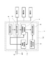
- FIG. 2 is a block diagram showing a configuration example of the flow rate measuring device 1 according to the embodiment of the present invention.
- the flow rate measuring device 1 is provided in a flow path 20 that supplies a fluid to be measured to instruments A, B, and C (fluid use instrument) connected to the downstream side.
- the instruments A to C are instruments that use the supplied fluid to be measured, and are connected to the flow rate measuring device 1 in parallel.
- the fluid to be measured is city gas, but is not limited to this, and can be applied to various liquids and gases without changing the gist of the present invention.
- a gas stove, a water heater, and a heating appliance are illustrated as an appliance using city gas, it is not limited to this.
- the flow measurement device 1 has a flow measurement unit 2 and a measurement data processing unit 10.
- the flow rate measuring unit 2 measures the flow rate Q of the fluid to be measured in the flow path 20.
- the flow rate measurement unit 2 is, for example, an ultrasonic measurement unit, and measures the flow rate Q of the fluid to be measured using the propagation time of the ultrasonic waves. Note that the measurement method of the flow rate measuring unit 2 is not limited to this.
- the flow rate measurement unit 2 measures the flow rate Q of the fluid to be measured in the flow path 20 at a predetermined time timing based on a signal from the time measurement unit 3 described later.
- the measurement data processing unit 10 includes, for example, a control unit having a computing unit such as a CPU and a storage unit having a memory such as a ROM and a RAM.
- the measurement data processing unit 10 may be configured by a single controller that performs centralized control, or may be configured by a plurality of controllers that perform distributed control in cooperation with each other.
- the measurement data processing unit 10 includes a time measurement unit 3, a measurement information calculation unit 4, a registration information storage unit 5, an appliance determination unit 6, and a history recording unit 11.
- the time measurement unit 3, the measurement information calculation unit 4, and the appliance determination unit 6 are functional blocks realized by the control unit executing a predetermined control program stored in the storage unit.
- the time measuring unit 3 is a processing unit that generates a timing signal at a predetermined time interval (sampling interval). In the present embodiment, the time measuring unit 3 issues a timing signal at a time interval of 0.5 s.
- the measurement information calculation unit 4 performs various calculations based on the flow rate Q of the fluid to be measured measured by the flow rate measurement unit 2 at predetermined time intervals and the time information from the time measurement unit 3.
- the process executed by the measurement information calculation unit 4 includes a process for calculating the unit time flow rate difference m, a process for determining whether or not the sign of the unit time flow rate difference m is inverted, and a gradient ⁇ of the unit time flow rate difference m. And a process for determining whether or not the gradient ⁇ is within a predetermined range.
- the unit time flow rate difference m is a signed value and is determined based on the following equation.
- the gradient ⁇ is a gradient of change with time of the unit time flow rate difference m, and is determined based on the following equation.
- the registered information storage unit 5 stores in advance a numerical range of the gradient ⁇ related to at least one instrument. This numerical range is a value obtained and set in advance by experiments.
- the appliance discriminating unit 6 specifies the appliance to be used when it is determined that the gradient ⁇ calculated by the measurement information calculating unit 4 is within the numerical range of the gradient ⁇ stored in the registered information storage unit 5.
- the history recording unit 11 records the history of the flow rate Q at the time t measured by the flow rate measuring unit 2 and the unit time flow rate difference m.
- FIG. 3 is a flowchart showing an operation example of the flow rate measuring device 1.
- the flow rate measurement unit 2 passes the flow path 20 based on the timing signal from the time measurement unit 3 in process S1.
- the flow rate Q of the fluid to be measured flowing is measured. That is, the flow rate measurement unit 2 measures the flow rate Q of the fluid to be measured in the flow path 20 at every time ⁇ t defined by the time measurement unit 3.
- the measurement information calculation unit 4 of the measurement data processing unit 10 calculates a unit time flow rate difference m from the previously obtained flow rate Q based on the flow rate Q obtained in step S1. Then, the measurement data processing unit 10 records the history of the flow rate Q and the unit time flow rate difference m at time t in the history recording unit 11.
- the measurement information calculation unit 4 of the measurement data processing unit 10 determines whether the sign of the unit time flow rate difference m calculated in the process S2 is inverted.
- the measurement data processing unit 10 executes the process S1 again.
- the measurement information calculation unit 4 of the measurement data processing unit 10 determines that the sign of the unit time flow rate difference m calculated in the process S2 is reversed (Yes in the process S3), the measurement information of the measurement data processing unit 10 The calculation unit 4 calculates the gradient ⁇ in process S4.
- the measurement information calculation unit 4 of the measurement data processing unit 10 determines whether the gradient ⁇ is within a predetermined numerical range.
- the predetermined numerical range of the gradient ⁇ is stored in the registration information storage unit 5.
- the measurement data processing unit 10 executes the process S1 again.
- the instrument determination unit 6 of the measurement data processing unit 10 determines in the process S6. It is specified that the device used is a specific fluid using device corresponding to a predetermined numerical range of the gradient ⁇ stored in the registered information storage unit 5. As a result, it is possible to specify that the appliance having the unique characteristics is being operated.
- This example is an example in the case of using a gas stove exhibiting the above-mentioned predetermined characteristics, and the instrument A is this type of instrument. Moreover, the instrument B and the instrument C are the types of instruments which have only one intrinsic flow rate.
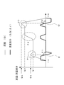
- FIG. 4 is a time chart showing the flow rate Q and the flow rate difference m when the gas stove (apparatus A) having the above-mentioned predetermined characteristics is used, the time change of the flow rate Q is shown by a thin line, and the unit time flow rate difference m Is indicated by a bold line.
- the time-dependent change in the unit time flow rate difference m calculated by the measurement information calculation unit 4 in the process S2 is the unit time flow rate at the time t1 when the gas is supplied to the burner at the maximum flow rate, as shown by the thick line in FIG.
- the difference m becomes 0, and the sign of the unit time flow rate difference m is inverted before and after that. Accordingly, in process S3, the measurement data processing unit 10 determines Yes, calculates the gradient ⁇ 1 at t1 (process S4), and determines whether this gradient ⁇ 1 falls within a predetermined numerical range (process S5).
- the measurement data processing unit 10 determines that the gradient ⁇ 1 falls within a predetermined numerical range (Yes in step S5), and the measurement data processing unit 10 determines that the gradient ⁇ stored in the registration information storage unit 5 is the instrument to be used. It is determined that the specific fluid use device A corresponds to the predetermined numerical range.
- the device B and the device C are devices of a type having only one inherent flow rate. If the device B or the device C is used, the unit time flow rate difference m at the time of ignition is: When it changes from 0 to a positive value and reaches the specific flow rate of the instrument, the unit time flow rate difference m changes from a positive value to 0. Therefore, in the instrument B and the instrument C, unlike the instrument A, the unit time flow rate difference m does not continuously change from a positive value to a negative value. Therefore, the measurement data processing unit 10 can determine that the instrument used is not the instrument B and the instrument C but the instrument A.
- the unit time flow rate difference m is positive at the time of reversal. Change continuously from negative to negative.
- the measurement information calculation unit 4 of the measurement data processing unit 10 determines that the gradient ⁇ is not within the predetermined numerical range (processing S5), and the appliance determination unit 6 does not specify the appliance to be used. In this way, by defining the value of the gradient ⁇ within a predetermined range, it is possible to accurately specify the instrument to be used.
- the flow rate Q of the gas supplied to the burner of the gas stove increases. . That is, the gas flow rate Q in the flow path 20 measured by the flow rate measuring unit 2 increases from Q1 to the set flow rate Q2 when the operation knob 111 is located at the use thermal power position, as shown in the P2 part of FIG. .
- the unit time flow rate difference m calculated by the measurement information calculation unit 4 in the process S2 is as shown in FIG. 4 while the operation knob 111 is rotated from the medium fire position toward the high fire position. It changes from 0 to a predetermined positive value.
- the unit time flow rate difference m changes from a positive value to zero.
- the measurement data processing unit 10 determines No in the process S3 and performs the process S1 again. Execute.
- the measurement data processing unit 10 does not determine the device used in the thermal power adjustment operation.
- the time-dependent change in the unit time flow rate difference m calculated by the measurement information calculation unit 4 in the process S2 is the unit time flow rate at the time t2 when the gas is supplied to the burner at the maximum flow rate, as shown by the thick line in FIG.
- the difference m becomes 0, and the sign of the unit time flow rate difference m is inverted before and after that. Accordingly, in process S3, the measurement data processing unit 10 determines Yes, calculates the gradient ⁇ 2 at t2 (process S4), and determines whether or not the gradient ⁇ 2 falls within a predetermined numerical range (process S5).
- the measurement data processing unit 10 determines that the gradient ⁇ 2 falls within a predetermined numerical range (processing S5), and the measurement data processing unit 10 determines that the instrument to be used has a predetermined value of the gradient ⁇ stored in the registration information storage unit 5. It is specified that it is a specific fluid use device A corresponding to the numerical range.
- the measurement data processing unit 10 calculates the gradient ⁇ of the unit time flow rate difference at the time when the sign of the unit time flow rate difference m is reversed, and this gradient ⁇ . Whether or not the fluid use device is a specific fluid use device is determined based on whether or not the fluid use device is within a predetermined range. As a result, it is possible to accurately determine that a specific fluid using instrument is being used among the devices connected to the flow rate measuring device 1. Therefore, it is possible to detect the use state of the manual operation instrument that is difficult to discriminate as compared with the microcomputer control device.
- the measurement data processing unit 10 starts using a specific instrument based on the history of the flow rate Q recorded in the history recording unit 11 in the process after the process S6. May be specified. That is, for example, when the measurement data processing unit 10 determines that a specific instrument A is being used, for example, by the user performing a use start operation of the instrument, the history of the flow rate Q corresponding to this determination is a predetermined flow rate ( For example, the use start time ts of a specific device may be specified based on the fact that the change starts from 0). Thereby, the usage amount of the fluid to be measured from the start of use by a specific instrument can be integrated.
- the measurement data processing unit 10 uses a specific instrument based on the history of the flow rate Q recorded in the history recording unit 11 in the processing after the processing S6.
- the stop time may be specified. That is, for example, when the measurement data processing unit 10 determines that a specific instrument A is being used by performing a fire extinguishing operation, for example, the history of the flow rate Q corresponding to this determination is a predetermined flow rate (for example, 0).
- the use stop time te of a specific instrument may be specified based on the fact that the change has been completed. Thereby, the usage amount of the fluid to be measured up to the time when the use of the specific instrument is stopped can be integrated.
- the flow rate measurement unit 2 measures the flow rate of the flow path 20 at a measurement timing of 0.5 seconds based on the timing signal received from the time measurement unit 3.
- the unit time of the measurement timing may be shorter than the above time.
- the operation for specifying the tool to be used when one tool is used at the same time has been described.
- the present invention is applicable to the determination of the tool to be used when a plurality of tools are used at the same time. Can do.
- the flow rate of the fluid to be measured for each instrument may be calculated based on a known algorithm, and the instrument used may be specified based on the calculation result.
- the flow measuring device can reliably determine a specific instrument by determining whether the gradient at the time of sign change of the unit time flow rate difference is within a predetermined range. As a technique for discriminating appliances having such characteristics, it can be widely applied.
Abstract
The invention is provided with: a flow rate measurement unit (2) that measures the flow rate of a fluid in a channel for providing the fluid to a fluid-using appliance; and a measurement data processing unit (10) that computes the slope of the change in a unit-time flow rate difference over time when the sign of the unit-time flow rate difference reverses, said slope being computed on the basis of the flow rate of the fluid measured by the flow rate measurement unit, and on the basis of whether the slope is within a specified range, assesses whether the fluid-using appliance is a specific fluid-using appliance.
Description
本発明は、ガス流量から使用ガス器具を判別する流量計測装置に関するものである。
The present invention relates to a flow rate measuring device for discriminating a gas appliance to be used from a gas flow rate.
従来、ガス機器固有の流量値より器具を特定する技術は世の中で知られている(例えば、特許文献1参照)。
Conventionally, a technique for specifying an appliance from a flow rate specific to a gas device is known in the world (see, for example, Patent Document 1).
この技術に関するガスメータは、家庭用ガス供給管に接続されガス流量を計測する流量計測手段と、登録記憶手段に記憶された使用するガス器具の流量パターンと流量計測手段で計測されるガス流量値とを比較し、使用ガス器具を判定する器具判定手段とを備える。
A gas meter related to this technology includes a flow rate measuring unit connected to a household gas supply pipe and measuring a gas flow rate, a flow pattern of a gas appliance to be used stored in a registration storage unit, and a gas flow rate value measured by the flow rate measuring unit. And a device determination means for determining a gas device to be used.
しかしながら、上記従来のガス器具は、異なるガス器具で、同じ流量値のものが存在する場合には、流量パターンから使用ガス器具を判定することが困難であった。
However, when the above conventional gas appliances are different gas appliances and have the same flow rate value, it is difficult to determine the gas appliance to be used from the flow rate pattern.
本発明は、前記従来の課題を解決するもので、同じ流量値の流体使用器具が存在していても特定の流体使用器具を判別することが可能な流量計測装置を提供することを目的としている。
SUMMARY OF THE INVENTION The present invention solves the above-described conventional problems, and an object thereof is to provide a flow rate measuring device capable of discriminating a specific fluid using device even when a fluid using device having the same flow rate value exists. .
前記従来の課題を解決するために、本発明のある態様に係る流量計測装置は、流体使用器具に流体を供給するための流路における流体の流量を計測する流量計測部と、前記流量計測部が計測した流体の流量に基づいて単位時間流量差分の符号が反転した時点における当該単位時間流量差分の経時変化の勾配を算出し、前記勾配が所定の範囲内であるか否かに基づいて、前記流体使用器具が特定の流体使用器具であるか否か判定する計測データ処理部と、を備える。
In order to solve the above-described conventional problems, a flow rate measurement device according to an aspect of the present invention includes a flow rate measurement unit that measures a flow rate of a fluid in a flow path for supplying a fluid to a fluid use instrument, and the flow rate measurement unit. Calculates the gradient of the change over time of the unit time flow rate difference when the sign of the unit time flow rate difference is reversed based on the measured fluid flow rate, and based on whether the gradient is within a predetermined range, A measurement data processing unit that determines whether or not the fluid use instrument is a specific fluid use instrument.
本発明の流量計測装置は、同じ流量値の器具が存在していても、特定の流体使用器具を判別することができる。
The flow rate measuring device of the present invention can discriminate a specific fluid use tool even if a tool having the same flow rate value exists.
第1の発明に係る流量計測装置は、流体使用器具に流体を供給するための流路における流体の流量を計測する流量計測部と、前記流量計測部が計測した流体の流量に基づいて単位時間流量差分の符号が反転した時点における当該単位時間流量差分の経時変化の勾配を算出し、前記勾配が所定の範囲内であるか否かに基づいて、前記流体使用器具が特定の流体使用器具であるか否か判定する計測データ処理部と、を備える。
According to a first aspect of the present invention, there is provided a flow rate measuring device that measures a flow rate of a fluid in a flow path for supplying a fluid to a fluid using instrument, and unit time based on the flow rate of the fluid measured by the flow rate measuring unit. A gradient of change over time of the unit time flow rate difference at the time when the sign of the flow rate difference is inverted, and based on whether the gradient is within a predetermined range, the fluid using device is a specific fluid using device. A measurement data processing unit for determining whether or not there is.
この構成によれば、特定の流体使用器具が流体を使用していることを精度よく判定することができる。
According to this configuration, it is possible to accurately determine that a specific fluid use device is using fluid.
第2の発明に係る流量計測装置は、特に第1の発明に係る流量計測装置において、前記流量計測部が計測した前記流量の履歴を記録する履歴記録部を備え、前記計測データ処理部は、前記流体使用器具が前記特定の器具であると判定した場合において、前記履歴記録部に記録された前記流量の履歴に基づいて前記特定の器具の使用開始時及び使用停止時の少なくともいずれかを特定してもよいものである。
A flow rate measuring device according to a second invention is a flow rate measuring device according to the first invention, particularly comprising a history recording unit for recording a history of the flow rate measured by the flow rate measuring unit, wherein the measurement data processing unit is When it is determined that the fluid use device is the specific device, at least one of the start time and the stop time of use of the specific device is specified based on the flow rate history recorded in the history recording unit. You may do it.
これによって、特定の器具が使用した流体の量を積算することができる。
This makes it possible to integrate the amount of fluid used by a specific instrument.
第3の発明に係る流量計測装置は、特に第2の発明に係る流量計測装置において、前記計測データ処理部は、前記判定に対応する前記流量の履歴が所定の流量から立ち上がるようにして変化を開始したことに基づいて前記特定の器具の使用開始時を特定してもよいものである。
A flow rate measuring device according to a third invention is the flow rate measuring device according to the second invention, in which the measurement data processing unit changes the flow rate history corresponding to the determination so as to rise from a predetermined flow rate. The start time of use of the specific device may be specified based on the start.
これによって、特定の器具の使用開始時を精度よく特定することができる。
This makes it possible to accurately specify when to start using a specific instrument.
第4の発明に係る流量計測装置は、特に第2の発明に係る流量計測装置において、前記計測データ処理部は、前記判定に対応する前記流量の履歴が所定の流量に立ち下がるようにして変化が終了したことに基づいて前記特定の器具の使用停止時を特定してもよいものである。ここで「流量が立ち下がる」とは、流量がある勾配で所定の流量に変化することを意味する。
The flow rate measurement device according to a fourth aspect of the invention is particularly the flow rate measurement device according to the second aspect of the invention, wherein the measurement data processing unit changes such that the flow rate history corresponding to the determination falls to a predetermined flow rate. When the use of the specific device is stopped may be specified based on the fact that the operation is completed. Here, “the flow rate falls” means that the flow rate changes to a predetermined flow rate with a certain gradient.
これによって、特定の器具の使用停止時を精度よく特定することができる。
This makes it possible to accurately identify when a specific instrument is stopped.
以下、本発明の実施の形態について、図面を参照しながら説明する。なお、この実施の形態によって本発明が限定されるものではない。また、以下では、全ての図を通じて、同一又は相当する要素には同一の参照符号を付して、その重複する説明を省略する。
Hereinafter, embodiments of the present invention will be described with reference to the drawings. Note that the present invention is not limited to the embodiments. In the following description, the same or corresponding elements are denoted by the same reference symbols throughout the drawings, and redundant description thereof is omitted.
(本発明の基礎となった知見)
図1は、所定の特性を示すガスコンロの操作摘み111を示す図である。 (Knowledge that became the basis of the present invention)
FIG. 1 is a diagram showing anoperation knob 111 of a gas stove showing predetermined characteristics.
図1は、所定の特性を示すガスコンロの操作摘み111を示す図である。 (Knowledge that became the basis of the present invention)
FIG. 1 is a diagram showing an
本発明は、以下に示す特定のガスコンロの特性に関する知見に基づいている。
The present invention is based on the following knowledge regarding the characteristics of a specific gas stove.
図1に示すように、このガスコンロは、操作軸に連結されている操作摘み111を備え、この操作摘み111を回動させることによって、バーナに供給するガス量を調節することができるように構成されている。
As shown in FIG. 1, the gas stove includes an operation knob 111 connected to an operation shaft, and is configured so that the amount of gas supplied to the burner can be adjusted by rotating the operation knob 111. Has been.
そして、このガスコンロは、操作摘み111の弱火位置、中火位置、強火位置及び消火位置が時計回り方向に順に並ぶように構成されている。
And this gas stove is constituted so that the low fire position, medium fire position, high fire position and fire extinguishing position of the operation knob 111 are arranged in order in the clockwise direction.
したがって、このガスコンロは、操作摘み111を消火位置から反時計回り方向に回動させると、ガスコンロのバーナにガスが最大流量で供給され始める。そして、更に操作摘み111を反時計回り方向に回動させると、バーナに供給されるガスの流量は、次第に減少するように構成されている。また、操作摘み11を弱火位置から消火位置に向かって回転させると、バーナに供給されるガス量は次第に増加し、操作摘み111が消火位置に達する直前でバーナにガスが最大流量で供給される。そして、この位置から操作摘み111を更に時計回り方向に回転させ、操作摘み111が消火位置に達すると、バーナに供給されるガスは遮断される。
Therefore, when the operation knob 111 is rotated counterclockwise from the fire extinguishing position, the gas stove starts to supply gas at the maximum flow rate to the burner of the gas stove. Further, when the operation knob 111 is further rotated counterclockwise, the flow rate of the gas supplied to the burner is gradually reduced. When the operation knob 11 is rotated from the low fire position toward the fire extinguishing position, the amount of gas supplied to the burner gradually increases, and the gas is supplied to the burner at the maximum flow rate immediately before the operation knob 111 reaches the fire extinguishing position. . When the operation knob 111 is further rotated clockwise from this position and the operation knob 111 reaches the fire extinguishing position, the gas supplied to the burner is shut off.
本発明は、このような特性を示すガスコンロに関する知見に基づくものである。
The present invention is based on the knowledge about a gas stove showing such characteristics.
(実施の形態)
本発明の実施の形態について、図2~図6を用いて説明する。 (Embodiment)
Embodiments of the present invention will be described with reference to FIGS.
本発明の実施の形態について、図2~図6を用いて説明する。 (Embodiment)
Embodiments of the present invention will be described with reference to FIGS.
(構成)
図2は、本発明の実施の形態に係る流量計測装置1の構成例を示すブロック図である。 (Constitution)
FIG. 2 is a block diagram showing a configuration example of the flow rate measuringdevice 1 according to the embodiment of the present invention.
図2は、本発明の実施の形態に係る流量計測装置1の構成例を示すブロック図である。 (Constitution)
FIG. 2 is a block diagram showing a configuration example of the flow rate measuring
図2に示すように、流量計測装置1は、下流側に接続された器具A、器具B、器具C(流体使用器具)に被計測流体を供給する流路20に設けられている。器具A~Cは、供給された被計測流体を使用する器具であり、流量計測装置1に対して並列に接続されている。本実施の形態において、被計測流体は、都市ガスであるが、これに限定されるものではなく、本発明の要旨を変更しない範囲で、種々の液体及び気体に適用することができる。また、都市ガスを使用する器具として、ガスコンロ、給湯器及び暖房器具が例示されるがこれに限定されるものではない。
As shown in FIG. 2, the flow rate measuring device 1 is provided in a flow path 20 that supplies a fluid to be measured to instruments A, B, and C (fluid use instrument) connected to the downstream side. The instruments A to C are instruments that use the supplied fluid to be measured, and are connected to the flow rate measuring device 1 in parallel. In the present embodiment, the fluid to be measured is city gas, but is not limited to this, and can be applied to various liquids and gases without changing the gist of the present invention. Moreover, although a gas stove, a water heater, and a heating appliance are illustrated as an appliance using city gas, it is not limited to this.
そして、流量計測装置1は、流量計測部2、及び計測データ処理部10を有している。
And the flow measurement device 1 has a flow measurement unit 2 and a measurement data processing unit 10.
流量計測部2は、流路20における被計測流体の流量Qを計測する。本実施の形態において、流量計測部2は、例えば、超音波式の計測部であり、超音波の伝播時間を利用して被計測流体の流量Qを計測するものである。なお、流量計測部2の計測方式は、これに限定されるものではない。流量計測部2は、後述する時間計測部3の信号に基づき所定の時間タイミングで流路20の被計測流体の流量Qの計測を行う。
The flow rate measuring unit 2 measures the flow rate Q of the fluid to be measured in the flow path 20. In the present embodiment, the flow rate measurement unit 2 is, for example, an ultrasonic measurement unit, and measures the flow rate Q of the fluid to be measured using the propagation time of the ultrasonic waves. Note that the measurement method of the flow rate measuring unit 2 is not limited to this. The flow rate measurement unit 2 measures the flow rate Q of the fluid to be measured in the flow path 20 at a predetermined time timing based on a signal from the time measurement unit 3 described later.
計測データ処理部10は、例えば、CPU等の演算器を有する制御部と、ROM及びRAM等のメモリを有する記憶部とを備えている。計測データ処理部10は、集中制御する単独の制御器で構成されていてもよく、互いに協働して分散制御する複数の制御器で構成されてもよい。
The measurement data processing unit 10 includes, for example, a control unit having a computing unit such as a CPU and a storage unit having a memory such as a ROM and a RAM. The measurement data processing unit 10 may be configured by a single controller that performs centralized control, or may be configured by a plurality of controllers that perform distributed control in cooperation with each other.
そして、計測データ処理部10は、時間計測部3、計測情報演算部4、登録情報記憶部5、器具判別部6及び履歴記録部11を含む。時間計測部3、計測情報演算部4、器具判別部6は、記憶部に格納された所定の制御プログラムを制御部が実行することにより実現される機能ブロックである。
The measurement data processing unit 10 includes a time measurement unit 3, a measurement information calculation unit 4, a registration information storage unit 5, an appliance determination unit 6, and a history recording unit 11. The time measurement unit 3, the measurement information calculation unit 4, and the appliance determination unit 6 are functional blocks realized by the control unit executing a predetermined control program stored in the storage unit.
時間計測部3は、所定の時間間隔(サンプリング間隔)でタイミング信号を発する処理部である。本実施の形態において、時間計測部3は、0.5sの時間間隔でタイミング信号を発する。
The time measuring unit 3 is a processing unit that generates a timing signal at a predetermined time interval (sampling interval). In the present embodiment, the time measuring unit 3 issues a timing signal at a time interval of 0.5 s.
計測情報演算部4は、流量計測部2が所定の時間間隔で計測した被計測流体の流量Q及び時間計測部3からの時間情報に基づいて各種演算を行う。計測情報演算部4が実行する処理には、単位時間流量差分mを算出する処理、単位時間流量差分mの符号が反転した時点の有無を判定する処理、単位時間流量差分mの勾配θを算出する処理、及びこの勾配θが所定の範囲内であるか否かを判定する処理が含まれる。
The measurement information calculation unit 4 performs various calculations based on the flow rate Q of the fluid to be measured measured by the flow rate measurement unit 2 at predetermined time intervals and the time information from the time measurement unit 3. The process executed by the measurement information calculation unit 4 includes a process for calculating the unit time flow rate difference m, a process for determining whether or not the sign of the unit time flow rate difference m is inverted, and a gradient θ of the unit time flow rate difference m. And a process for determining whether or not the gradient θ is within a predetermined range.
ここで、単位時間流量差分mは、符号付きの値であり、次式に基づいて決定される。
Here, the unit time flow rate difference m is a signed value and is determined based on the following equation.
m=ΔQ/Δt
ΔQ:所定の時間間隔Δtの前後における流量Qの符号付き変化量
Δt:時間計測部3が発するタイミング信号の時間間隔 m = ΔQ / Δt
ΔQ: Signed change amount of the flow rate Q before and after the predetermined time interval Δt Δt: Time interval of the timing signal generated by thetime measuring unit 3
ΔQ:所定の時間間隔Δtの前後における流量Qの符号付き変化量
Δt:時間計測部3が発するタイミング信号の時間間隔 m = ΔQ / Δt
ΔQ: Signed change amount of the flow rate Q before and after the predetermined time interval Δt Δt: Time interval of the timing signal generated by the
また、勾配θは単位時間流量差分mの経時変化の勾配であり、次式に基づいて決定される。
Further, the gradient θ is a gradient of change with time of the unit time flow rate difference m, and is determined based on the following equation.
θ=Δm/Δt
Θ = Δm / Δt
登録情報記憶部5には、少なくとも1つの器具に係る勾配θの数値範囲が予め格納されている。この数値範囲は、実験によって予め求められ設定される値である。
The registered information storage unit 5 stores in advance a numerical range of the gradient θ related to at least one instrument. This numerical range is a value obtained and set in advance by experiments.
器具判別部6は、計測情報演算部4において算出した勾配θが、登録情報記憶部5に記憶された勾配θの数値範囲内であると判定された場合に、使用器具を特定する。
The appliance discriminating unit 6 specifies the appliance to be used when it is determined that the gradient θ calculated by the measurement information calculating unit 4 is within the numerical range of the gradient θ stored in the registered information storage unit 5.
履歴記録部11は、流量計測部2が計測した時刻tにおける流量Q、単位時間流量差分mの履歴を記録する。
The history recording unit 11 records the history of the flow rate Q at the time t measured by the flow rate measuring unit 2 and the unit time flow rate difference m.
なお、図中の矢印は、信号の伝達方向を示す。
Note that the arrows in the figure indicate the signal transmission direction.
(動作例)
図3は、流量計測装置1の動作例を示すフローチャートである。 (Operation example)
FIG. 3 is a flowchart showing an operation example of the flowrate measuring device 1.
図3は、流量計測装置1の動作例を示すフローチャートである。 (Operation example)
FIG. 3 is a flowchart showing an operation example of the flow
まず、被計測流体は、矢印Aの方向から流量計測装置1の流量計測部2に流入すると、処理S1において、流量計測部2は、時間計測部3からのタイミング信号に基づいて流路20を流れる被計測流体の流量Qを計測する。すなわち、流量計測部2は、時間計測部3によって規定された時間Δtごとに流路20における被計測流体の流量Qを計測する。
First, when the fluid to be measured flows into the flow rate measurement unit 2 of the flow rate measurement device 1 from the direction of the arrow A, the flow rate measurement unit 2 passes the flow path 20 based on the timing signal from the time measurement unit 3 in process S1. The flow rate Q of the fluid to be measured flowing is measured. That is, the flow rate measurement unit 2 measures the flow rate Q of the fluid to be measured in the flow path 20 at every time Δt defined by the time measurement unit 3.
次に、処理S2において、計測データ処理部10の計測情報演算部4は、処理S1において得られた流量Qに基づいて、前回得られた流量Qとの単位時間流量差分mを算出する。そして、計測データ処理部10は、時刻tにおける流量Q、単位時間流量差分mの履歴を履歴記録部11に記録する。
Next, in process S2, the measurement information calculation unit 4 of the measurement data processing unit 10 calculates a unit time flow rate difference m from the previously obtained flow rate Q based on the flow rate Q obtained in step S1. Then, the measurement data processing unit 10 records the history of the flow rate Q and the unit time flow rate difference m at time t in the history recording unit 11.
次に、処理S3において、計測データ処理部10の計測情報演算部4は、処理S2で計算された単位時間流量差分mの符号が反転したかどうかを判定する。
Next, in the process S3, the measurement information calculation unit 4 of the measurement data processing unit 10 determines whether the sign of the unit time flow rate difference m calculated in the process S2 is inverted.
そして、計測データ処理部10の計測情報演算部4が単位時間流量差分mの符号が反転していないと判定すると(処理S3においてNo)、計測データ処理部10は再度処理S1を実行する。
When the measurement information calculation unit 4 of the measurement data processing unit 10 determines that the sign of the unit time flow rate difference m is not inverted (No in the process S3), the measurement data processing unit 10 executes the process S1 again.
その一方で、計測データ処理部10の計測情報演算部4が処理S2で計算された単位時間流量差分mの符号が反転したと判定すると(処理S3においてYes)、計測データ処理部10の計測情報演算部4は、処理S4において、勾配θを算出する。
On the other hand, when the measurement information calculation unit 4 of the measurement data processing unit 10 determines that the sign of the unit time flow rate difference m calculated in the process S2 is reversed (Yes in the process S3), the measurement information of the measurement data processing unit 10 The calculation unit 4 calculates the gradient θ in process S4.
次に、処理S5において、計測データ処理部10の計測情報演算部4は、勾配θが所定の数値範囲かどうかを判定する。この勾配θの所定の数値範囲は、登録情報記憶部5に記憶されている。
Next, in process S5, the measurement information calculation unit 4 of the measurement data processing unit 10 determines whether the gradient θ is within a predetermined numerical range. The predetermined numerical range of the gradient θ is stored in the registration information storage unit 5.
そして、計測データ処理部10の計測情報演算部4が勾配θが所定の数値範囲に入っていないと判定すると(処理S5においてNo)、計測データ処理部10は再度処理S1を実行する。
When the measurement information calculation unit 4 of the measurement data processing unit 10 determines that the gradient θ is not within the predetermined numerical range (No in the process S5), the measurement data processing unit 10 executes the process S1 again.
その一方で、計測データ処理部10の計測情報演算部4が勾配θが所定の範囲であると判定すると(処理S5においてYes)、計測データ処理部10の器具判別部6は、処理S6において、使用器具が登録情報記憶部5に記憶されている勾配θの所定の数値範囲に対応する特定の流体使用器具であると特定する。これによって、固有の特性を有している器具の運転が行われていることを特定することができる。
On the other hand, when the measurement information calculation unit 4 of the measurement data processing unit 10 determines that the gradient θ is within the predetermined range (Yes in the process S5), the instrument determination unit 6 of the measurement data processing unit 10 determines in the process S6. It is specified that the device used is a specific fluid using device corresponding to a predetermined numerical range of the gradient θ stored in the registered information storage unit 5. As a result, it is possible to specify that the appliance having the unique characteristics is being operated.
そして、被計測流体は、各器具に流れ込む。
And the fluid to be measured flows into each instrument.
(実施例)
以下、本発明に係る具体的な実施例について、図面を参照しながら詳細に説明する。 (Example)
Hereinafter, specific embodiments according to the present invention will be described in detail with reference to the drawings.
以下、本発明に係る具体的な実施例について、図面を参照しながら詳細に説明する。 (Example)
Hereinafter, specific embodiments according to the present invention will be described in detail with reference to the drawings.
本実施例は、上記所定の特性を示すガスコンロを使用した場合の実施例であり、器具Aがこの種のタイプの器具である。また、器具B、及び器具Cは、固有流量をひとつしか持たないタイプの器具である。
This example is an example in the case of using a gas stove exhibiting the above-mentioned predetermined characteristics, and the instrument A is this type of instrument. Moreover, the instrument B and the instrument C are the types of instruments which have only one intrinsic flow rate.
図4は、上記所定の特性を示すガスコンロ(器具A)を使用したときの流量Q及び流量差分mを示すタイムチャートであり、流量Qの時間変化を細線で示し、また、単位時間流量差分mを太線で示す。
FIG. 4 is a time chart showing the flow rate Q and the flow rate difference m when the gas stove (apparatus A) having the above-mentioned predetermined characteristics is used, the time change of the flow rate Q is shown by a thin line, and the unit time flow rate difference m Is indicated by a bold line.
まず、使用者が点火操作(器具の使用開始操作)を行ったときの動作について説明する。
First, the operation when the user performs an ignition operation (operation to start using the appliance) will be described.
図4に示すように、使用者が時間tsにおいて、ガスコンロを点火するため、使用者が操作摘み111を消火位置から点火位置である中火位置に向かって反時計回り方向に回動させると、ガスコンロのバーナにガスが最大流量で供給され始める。したがって、流量計測部2によって計測される流路20におけるガスの流量Qは、図4のP1部分において細線で示すように、Qaに増加する。その後、操作摘み111が中火位置に達すると、流量計測部2によって計測されるガスの流量Qは、Qaよりも減少し、中火位置における設定流量Q1となる。このように、ガスの流量は、一旦Qaに増加し、その直後、Qaよりも小さいQ1となる。
As shown in FIG. 4, when the user ignites the gas stove at time ts, when the user turns the operation knob 111 counterclockwise from the fire extinguishing position toward the medium fire position which is the ignition position, Gas begins to be supplied to the burner of the gas stove at the maximum flow rate. Accordingly, the gas flow rate Q in the flow path 20 measured by the flow rate measuring unit 2 increases to Qa as indicated by a thin line in the P1 portion of FIG. Thereafter, when the operation knob 111 reaches the medium fire position, the gas flow rate Q measured by the flow rate measuring unit 2 decreases from Qa and becomes the set flow rate Q1 at the medium fire position. Thus, the flow rate of the gas once increases to Qa, and immediately after that, becomes Q1 smaller than Qa.
したがって、処理S2において計測情報演算部4によって算出される単位時間流量差分mの経時変化は、図4において太線で示すように、バーナにガスが最大流量で供給された時点t1において、単位時間流量差分mは0となり、その前後において単位時間流量差分mの符号が反転する。したがって、処理S3において計測データ処理部10は、Yesと判定し、t1における勾配θ1の計算(処理S4)及び、この勾配θ1が所定の数値範囲に入るか否かを判定する(処理S5)。そして、計測データ処理部10は、勾配θ1が所定の数値範囲に入ると判定し(処理S5においてYes)、計測データ処理部10は、使用器具が登録情報記憶部5に記憶されている勾配θの所定の数値範囲に対応する特定の流体使用器具Aであると判定する。
Therefore, the time-dependent change in the unit time flow rate difference m calculated by the measurement information calculation unit 4 in the process S2 is the unit time flow rate at the time t1 when the gas is supplied to the burner at the maximum flow rate, as shown by the thick line in FIG. The difference m becomes 0, and the sign of the unit time flow rate difference m is inverted before and after that. Accordingly, in process S3, the measurement data processing unit 10 determines Yes, calculates the gradient θ1 at t1 (process S4), and determines whether this gradient θ1 falls within a predetermined numerical range (process S5). Then, the measurement data processing unit 10 determines that the gradient θ1 falls within a predetermined numerical range (Yes in step S5), and the measurement data processing unit 10 determines that the gradient θ stored in the registration information storage unit 5 is the instrument to be used. It is determined that the specific fluid use device A corresponds to the predetermined numerical range.
すなわち、上述の通り、器具B及び器具Cは、固有流量をひとつしか持たないタイプの器具であり、仮に、器具B又は器具Cが使用された場合は、点火時において単位時間流量差分mは、0から正の値に変化し、器具の固有流量に達すると単位時間流量差分mは、正の値から0に変化する。よって、器具B及び器具Cにおいては、器具Aと異なり、単位時間流量差分mが正の値から負の値に連続的に変化しない。よって、計測データ処理部10は、使用器具が器具B及び器具Cではなく、器具Aであると判定することができる。
That is, as described above, the device B and the device C are devices of a type having only one inherent flow rate. If the device B or the device C is used, the unit time flow rate difference m at the time of ignition is: When it changes from 0 to a positive value and reaches the specific flow rate of the instrument, the unit time flow rate difference m changes from a positive value to 0. Therefore, in the instrument B and the instrument C, unlike the instrument A, the unit time flow rate difference m does not continuously change from a positive value to a negative value. Therefore, the measurement data processing unit 10 can determine that the instrument used is not the instrument B and the instrument C but the instrument A.
ところで、火力調整操作において、操作摘み111を緩やかに所定の方向に回動させ、その後直ちに緩やかに操作摘み111を反対方向に回動させた場合においても、反転時に単位時間流量差分mが正の値から負の値に連続的に変化する。しかしこのような火力調整操作においては、流量計測部2が計測するガスの流量変化が通常比較的瞬時に行われる点火操作によるものよりも緩やかであるために、勾配θは、点火操作時と比較して小さな値をとる。したがって、計測データ処理部10の計測情報演算部4は、勾配θが所定の数値範囲に入っていないと判定し(処理S5)、器具判別部6による使用器具の特定が行われない。このように、勾配θの値を所定の範囲に定めることにより、使用器具を精度よく特定することができる。
By the way, in the thermal power adjustment operation, even when the operation knob 111 is gently rotated in a predetermined direction and immediately thereafter, the operation knob 111 is gently rotated in the opposite direction, the unit time flow rate difference m is positive at the time of reversal. Change continuously from negative to negative. However, in such a thermal power adjustment operation, since the change in the flow rate of the gas measured by the flow rate measuring unit 2 is generally slower than that caused by the ignition operation that is performed relatively instantaneously, the gradient θ is compared with that during the ignition operation. And take a small value. Therefore, the measurement information calculation unit 4 of the measurement data processing unit 10 determines that the gradient θ is not within the predetermined numerical range (processing S5), and the appliance determination unit 6 does not specify the appliance to be used. In this way, by defining the value of the gradient θ within a predetermined range, it is possible to accurately specify the instrument to be used.
次に、使用者が火力調整操作を行ったときの動作について説明する。
Next, the operation when the user performs the thermal power adjustment operation will be described.
使用者がガスコンロを中火から使用火力に強めるため、操作摘み111を中火位置から強火位置に向かって時計回り方向に回動させると、ガスコンロのバーナに供給されるガスの流量Qは増大する。すなわち、流量計測部2によって計測される流路20におけるガスの流量Qは、図4のP2部分に示すように、Q1から操作摘み111が使用火力位置に位置したときの設定流量Q2に増加する。
If the user rotates the operation knob 111 in the clockwise direction from the medium fire position toward the high fire position in order to strengthen the gas stove from medium fire to use fire power, the flow rate Q of the gas supplied to the burner of the gas stove increases. . That is, the gas flow rate Q in the flow path 20 measured by the flow rate measuring unit 2 increases from Q1 to the set flow rate Q2 when the operation knob 111 is located at the use thermal power position, as shown in the P2 part of FIG. .
したがって、処理S2において計測情報演算部4によって算出される単位時間流量差分mは、図4において太線で示すように、操作摘み111を中火位置から強火位置に向かって回動させている間、0から所定の正の値に変化する。そして、操作摘み111を使用火力位置で停止させると、単位時間流量差分mは、正の値から0に変化する。
Accordingly, the unit time flow rate difference m calculated by the measurement information calculation unit 4 in the process S2 is as shown in FIG. 4 while the operation knob 111 is rotated from the medium fire position toward the high fire position. It changes from 0 to a predetermined positive value. When the operation knob 111 is stopped at the use heat power position, the unit time flow rate difference m changes from a positive value to zero.
よって、使用者がこのような火力調整操作を行っている間、単位時間流量差分mの符号の反転は起きないため、処理S3において計測データ処理部10は、Noと判定し、再度処理S1を実行する。
Therefore, since the sign of the unit time flow rate difference m does not reverse while the user performs such a thermal power adjustment operation, the measurement data processing unit 10 determines No in the process S3 and performs the process S1 again. Execute.
すなわち、計測データ処理部10は、火力調整操作においては、使用機器の判定を行わない。
That is, the measurement data processing unit 10 does not determine the device used in the thermal power adjustment operation.
次に、使用者が消火操作(器具の使用停止操作)を行ったときの動作について説明する。
Next, the operation when the user performs a fire extinguishing operation (operation to stop using the appliance) will be described.
使用者が、ガスコンロを消火するため、使用者が操作摘み111を使用火力位置から消火位置に向かって時計回り方向に回動させると、ガスコンロのバーナにガスが一旦最大流量で供給される。したがって、流量計測部2によって計測される流路20におけるガスの流量Qは、図4のP3部分において細線で示すように、Qbに増加する。その後、時間teにおいて、操作摘み111が消火位置に達すると、ガスコンロのバーナに供給されるガスが遮断され、流量計測部2によって計測されるガスの流量Qは、0となる。このように、流量計測部2において計測されるガスの流量は、一旦Qbに増加し、その直後、0となる。
When the user turns the operation knob 111 clockwise from the use fire power position toward the fire extinguishing position in order to extinguish the gas stove, the gas is once supplied to the burner of the gas stove at the maximum flow rate. Therefore, the gas flow rate Q in the flow path 20 measured by the flow rate measuring unit 2 increases to Qb as indicated by a thin line in the P3 portion of FIG. Thereafter, when the operation knob 111 reaches the fire extinguishing position at time te, the gas supplied to the burner of the gas stove is shut off, and the gas flow rate Q measured by the flow rate measuring unit 2 becomes zero. Thus, the gas flow rate measured by the flow rate measuring unit 2 temporarily increases to Qb and immediately becomes 0.
したがって、処理S2において計測情報演算部4によって算出される単位時間流量差分mの経時変化は、図4において太線で示すように、バーナにガスが最大流量で供給された時点t2において、単位時間流量差分mは0となり、その前後において単位時間流量差分mの符号が反転する。したがって、処理S3において計測データ処理部10は、Yesと判定し、t2における勾配θ2の計算(処理S4)及び、この勾配θ2が所定の数値範囲に入るか否かを判定する(処理S5)。そして、計測データ処理部10は、勾配θ2が所定の数値範囲に入ると判定し(処理S5)、計測データ処理部10は、使用器具が登録情報記憶部5に記憶されている勾配θの所定の数値範囲に対応する特定の流体使用器具Aであると特定する。
Therefore, the time-dependent change in the unit time flow rate difference m calculated by the measurement information calculation unit 4 in the process S2 is the unit time flow rate at the time t2 when the gas is supplied to the burner at the maximum flow rate, as shown by the thick line in FIG. The difference m becomes 0, and the sign of the unit time flow rate difference m is inverted before and after that. Accordingly, in process S3, the measurement data processing unit 10 determines Yes, calculates the gradient θ2 at t2 (process S4), and determines whether or not the gradient θ2 falls within a predetermined numerical range (process S5). Then, the measurement data processing unit 10 determines that the gradient θ2 falls within a predetermined numerical range (processing S5), and the measurement data processing unit 10 determines that the instrument to be used has a predetermined value of the gradient θ stored in the registration information storage unit 5. It is specified that it is a specific fluid use device A corresponding to the numerical range.
以上に説明したように、本発明の流量計測装置は、計測データ処理部10が単位時間流量差分mの符号が反転した時点における単位時間流量差分の経時変化の勾配θを算出し、この勾配θが所定の範囲内であるか否かに基づいて、流体使用器具が特定の流体使用器具であるか否か判定する。これによって、流量計測装置1に接続されている機器のうち、特定の流体使用器具が使用されていることを精度よく判定することができる。したがって、マイコン制御機器と比較して判別が困難であった手動操作器具の使用状態を検出することができる。
As described above, in the flow rate measuring device of the present invention, the measurement data processing unit 10 calculates the gradient θ of the unit time flow rate difference at the time when the sign of the unit time flow rate difference m is reversed, and this gradient θ. Whether or not the fluid use device is a specific fluid use device is determined based on whether or not the fluid use device is within a predetermined range. As a result, it is possible to accurately determine that a specific fluid using instrument is being used among the devices connected to the flow rate measuring device 1. Therefore, it is possible to detect the use state of the manual operation instrument that is difficult to discriminate as compared with the microcomputer control device.
<変形例>
上記実施の形態において、図5に示すように、計測データ処理部10は、処理S6の後の処理において、履歴記録部11に記録された流量Qの履歴に基づいて特定の器具の使用開始時を特定してもよい。すなわち、例えば使用者が器具の使用開始操作を行ったことによって、特定の器具Aが使用されていると計測データ処理部10が判定すると、この判定に対応する流量Qの履歴が所定の流量(例えば0)から立ち上がるようにして変化を開始したことに基づいて特定の器具の使用開始時tsを特定してもよい。これによって、特定の器具による使用開始時からの被計測流体の使用量を積算することができる。 <Modification>
In the above embodiment, as shown in FIG. 5, the measurementdata processing unit 10 starts using a specific instrument based on the history of the flow rate Q recorded in the history recording unit 11 in the process after the process S6. May be specified. That is, for example, when the measurement data processing unit 10 determines that a specific instrument A is being used, for example, by the user performing a use start operation of the instrument, the history of the flow rate Q corresponding to this determination is a predetermined flow rate ( For example, the use start time ts of a specific device may be specified based on the fact that the change starts from 0). Thereby, the usage amount of the fluid to be measured from the start of use by a specific instrument can be integrated.
上記実施の形態において、図5に示すように、計測データ処理部10は、処理S6の後の処理において、履歴記録部11に記録された流量Qの履歴に基づいて特定の器具の使用開始時を特定してもよい。すなわち、例えば使用者が器具の使用開始操作を行ったことによって、特定の器具Aが使用されていると計測データ処理部10が判定すると、この判定に対応する流量Qの履歴が所定の流量(例えば0)から立ち上がるようにして変化を開始したことに基づいて特定の器具の使用開始時tsを特定してもよい。これによって、特定の器具による使用開始時からの被計測流体の使用量を積算することができる。 <Modification>
In the above embodiment, as shown in FIG. 5, the measurement
また、図5に示すように、上記実施の形態において、計測データ処理部10は、処理S6の後の処理において、履歴記録部11に記録された流量Qの履歴に基づいて特定の器具の使用停止時を特定してもよい。すなわち、例えば使用者が消火操作を行ったことによって、特定の器具Aが使用されていると計測データ処理部10が判定すると、この判定に対応する流量Qの履歴が所定の流量(例えば0)に収束するようにして変化が終了したことに基づいて特定の器具の使用停止時teを特定してもよい。これによって、特定の器具による使用停止時までの被計測流体の使用量を積算することができる。
Also, as shown in FIG. 5, in the above embodiment, the measurement data processing unit 10 uses a specific instrument based on the history of the flow rate Q recorded in the history recording unit 11 in the processing after the processing S6. The stop time may be specified. That is, for example, when the measurement data processing unit 10 determines that a specific instrument A is being used by performing a fire extinguishing operation, for example, the history of the flow rate Q corresponding to this determination is a predetermined flow rate (for example, 0). The use stop time te of a specific instrument may be specified based on the fact that the change has been completed. Thereby, the usage amount of the fluid to be measured up to the time when the use of the specific instrument is stopped can be integrated.
なお、本実施の形態において、流量計測部2は、時間計測部3から受信したタイミング信号に基づいて、0.5秒間隔の計測タイミングで流路20の流量を測定する。しかし、図4のA部、C部のような瞬時的な流量の変化を明確に捕捉することができない場合は計測タイミングの単位時間を上記の時間よりも短くしてもよい。
In the present embodiment, the flow rate measurement unit 2 measures the flow rate of the flow path 20 at a measurement timing of 0.5 seconds based on the timing signal received from the time measurement unit 3. However, in the case where the instantaneous change in the flow rate cannot be clearly captured as in the A part and the C part in FIG. 4, the unit time of the measurement timing may be shorter than the above time.
また、本実施の形態においては、使用器具が同時に1つ使用された場合における使用器具を特定する動作について説明したが、使用器具が同時に複数使用された場合における使用器具の判別にも適用することができる。この場合、周知のアルゴリズムに基づいて各器具に対する被計測流体の流量を算出し、この算出結果に基づいて使用器具を特定してもよい。
In the present embodiment, the operation for specifying the tool to be used when one tool is used at the same time has been described. However, the present invention is applicable to the determination of the tool to be used when a plurality of tools are used at the same time. Can do. In this case, the flow rate of the fluid to be measured for each instrument may be calculated based on a known algorithm, and the instrument used may be specified based on the calculation result.
上記説明から、当業者にとっては、本発明の多くの改良や他の実施形態が明らかである。従って、上記説明は、例示としてのみ解釈されるべきであり、本発明を実行する最良の態様を当業者に教示する目的で提供されたものである。本発明の精神を逸脱することなく、その構造及び/又は機能の詳細を実質的に変更できる。
From the above description, many modifications and other embodiments of the present invention are apparent to persons skilled in the art. Accordingly, the foregoing description should be construed as illustrative only and is provided for the purpose of teaching those skilled in the art the best mode of carrying out the invention. The details of the structure and / or function may be substantially changed without departing from the spirit of the invention.
以上のように、本発明にかかる流量計測装置は、単位時間流量差分の符号変化時の勾配が所定の範囲内かどうかを判定することにより、特定器具を確実に判別することができるため、このような特性を有する器具の判別技術として、幅広い応用ができるものである。
As described above, the flow measuring device according to the present invention can reliably determine a specific instrument by determining whether the gradient at the time of sign change of the unit time flow rate difference is within a predetermined range. As a technique for discriminating appliances having such characteristics, it can be widely applied.
1 流量計測装置
2 流量計測部
3 時間計測部
10 計測データ処理部
11 履歴記録部
20 流路 DESCRIPTION OFSYMBOLS 1 Flow measuring device 2 Flow measuring part 3 Time measuring part 10 Measurement data processing part 11 History recording part 20 Flow path
2 流量計測部
3 時間計測部
10 計測データ処理部
11 履歴記録部
20 流路 DESCRIPTION OF
Claims (4)
- 流体使用器具に流体を供給するための流路における流体の流量を計測する流量計測部と、
前記流量計測部が計測した流体の流量に基づいて単位時間流量差分の符号が反転した時点における当該単位時間流量差分の経時変化の勾配を算出し、前記勾配が所定の範囲内であるか否かに基づいて、前記流体使用器具が特定の流体使用器具であるか否か判定する計測データ処理部と、を備える、流量計測装置。 A flow rate measuring unit for measuring the flow rate of the fluid in the flow path for supplying fluid to the fluid using device;
Based on the flow rate of the fluid measured by the flow rate measurement unit, the gradient of the change over time of the unit time flow rate difference at the time when the sign of the unit time flow rate difference is inverted is calculated, and whether or not the gradient is within a predetermined range And a measurement data processing unit for determining whether or not the fluid use instrument is a specific fluid use instrument. - 前記流量計測部が計測した前記流量の履歴を記録する履歴記録部を備え、
前記計測データ処理部は、前記流体使用器具が前記特定の器具であると判定した場合において、前記履歴記録部に記録された前記流量の履歴に基づいて前記特定の器具の使用開始時及び使用停止時の少なくともいずれかを特定する、請求項1に記載の流量計測装置。 A history recording unit that records a history of the flow rate measured by the flow rate measurement unit;
When the measurement data processing unit determines that the fluid use device is the specific device, the measurement data processing unit starts and stops using the specific device based on the flow rate history recorded in the history recording unit. The flow rate measuring device according to claim 1, wherein at least one of times is specified. - 前記計測データ処理部は、前記判定に対応する前記流量の履歴が所定の流量から立ち上がるようにして変化を開始したことに基づいて前記特定の器具の使用開始時を特定する、請求項2に記載の流量計測装置。 The measurement data processing unit identifies the start time of use of the specific instrument based on the fact that the flow history corresponding to the determination starts to change from a predetermined flow rate. Flow measurement device.
- 前記計測データ処理部は、前記判定に対応する前記流量の履歴が所定の流量に立ち下がるようにして変化が終了したことに基づいて前記特定の器具の使用停止時を特定する、請求項2に記載の流量計測装置。 The measurement data processing unit identifies when the use of the specific instrument is stopped based on the fact that the change has been completed so that the flow rate history corresponding to the determination falls to a predetermined flow rate. The flow rate measuring device described.
Priority Applications (3)
| Application Number | Priority Date | Filing Date | Title |
|---|---|---|---|
| CN201380020350.8A CN104246453A (en) | 2012-04-17 | 2013-04-17 | Flow rate measurement device |
| EP13779025.9A EP2840365B1 (en) | 2012-04-17 | 2013-04-17 | Method for flow rate measurement |
| US14/394,566 US20150073731A1 (en) | 2012-04-17 | 2013-04-17 | Flow meter device |
Applications Claiming Priority (2)
| Application Number | Priority Date | Filing Date | Title |
|---|---|---|---|
| JP2012093625A JP2013221853A (en) | 2012-04-17 | 2012-04-17 | Flow rate measurement device |
| JP2012-093625 | 2012-04-17 |
Publications (1)
| Publication Number | Publication Date |
|---|---|
| WO2013157257A1 true WO2013157257A1 (en) | 2013-10-24 |
Family
ID=49383227
Family Applications (1)
| Application Number | Title | Priority Date | Filing Date |
|---|---|---|---|
| PCT/JP2013/002589 WO2013157257A1 (en) | 2012-04-17 | 2013-04-17 | Flow rate measurement device |
Country Status (5)
| Country | Link |
|---|---|
| US (1) | US20150073731A1 (en) |
| EP (1) | EP2840365B1 (en) |
| JP (1) | JP2013221853A (en) |
| CN (1) | CN104246453A (en) |
| WO (1) | WO2013157257A1 (en) |
Families Citing this family (2)
| Publication number | Priority date | Publication date | Assignee | Title |
|---|---|---|---|---|
| JP6381498B2 (en) * | 2015-09-02 | 2018-08-29 | 三菱電機ビルテクノサービス株式会社 | Weighing meter state change detection device and program |
| US10648842B2 (en) * | 2016-06-22 | 2020-05-12 | Benoit & Cote Inc. | Fluid flow measuring and control devices and method |
Citations (2)
| Publication number | Priority date | Publication date | Assignee | Title |
|---|---|---|---|---|
| JPH07151578A (en) * | 1993-11-29 | 1995-06-16 | Tokyo Gas Co Ltd | Flow rate variation discriminating device |
| JP2006200802A (en) | 2005-01-20 | 2006-08-03 | Matsushita Electric Ind Co Ltd | Gas meter |
Family Cites Families (15)
| Publication number | Priority date | Publication date | Assignee | Title |
|---|---|---|---|---|
| JP3720297B2 (en) * | 2001-12-27 | 2005-11-24 | 東京瓦斯株式会社 | Gas appliance determination device and gas meter having gas appliance determination function |
| TWI386629B (en) * | 2005-05-09 | 2013-02-21 | Panasonic Corp | Flow measurement device |
| JP4729971B2 (en) * | 2005-05-09 | 2011-07-20 | パナソニック株式会社 | Gas meter device |
| JP5092723B2 (en) * | 2006-12-11 | 2012-12-05 | パナソニック株式会社 | Flow measuring device |
| JP4935334B2 (en) * | 2006-12-11 | 2012-05-23 | パナソニック株式会社 | Flow rate measuring device and gas supply system using this device |
| CN102252728B (en) * | 2007-01-17 | 2013-09-25 | 松下电器产业株式会社 | Flow measurement apparatus and flow measurement method |
| JP4994875B2 (en) * | 2007-02-14 | 2012-08-08 | 東京瓦斯株式会社 | Gas appliance identification device |
| US9200939B2 (en) * | 2007-06-12 | 2015-12-01 | Panasonic Corporation | Flow rate measurement apparatus and fluid supply system |
| JP2009109054A (en) * | 2007-10-29 | 2009-05-21 | Panasonic Corp | Apparatus discriminating device |
| CN101960222A (en) * | 2008-03-06 | 2011-01-26 | 松下电器产业株式会社 | Instrument management system and gas supply system |
| JP5090995B2 (en) * | 2008-03-31 | 2012-12-05 | 東京瓦斯株式会社 | Gas meter with gas supply monitoring function |
| JP5287626B2 (en) * | 2009-03-03 | 2013-09-11 | パナソニック株式会社 | Flow measuring device |
| JP5589351B2 (en) * | 2009-11-02 | 2014-09-17 | パナソニック株式会社 | Flow measuring device |
| JP5623101B2 (en) * | 2010-03-12 | 2014-11-12 | パナソニック株式会社 | Gas flow measuring device |
| JP5914877B2 (en) * | 2011-11-17 | 2016-05-11 | パナソニックIpマネジメント株式会社 | Gas flow rate detection device and gas flow rate detection method |
-
2012
- 2012-04-17 JP JP2012093625A patent/JP2013221853A/en active Pending
-
2013
- 2013-04-17 US US14/394,566 patent/US20150073731A1/en not_active Abandoned
- 2013-04-17 CN CN201380020350.8A patent/CN104246453A/en active Pending
- 2013-04-17 EP EP13779025.9A patent/EP2840365B1/en active Active
- 2013-04-17 WO PCT/JP2013/002589 patent/WO2013157257A1/en active Application Filing
Patent Citations (2)
| Publication number | Priority date | Publication date | Assignee | Title |
|---|---|---|---|---|
| JPH07151578A (en) * | 1993-11-29 | 1995-06-16 | Tokyo Gas Co Ltd | Flow rate variation discriminating device |
| JP2006200802A (en) | 2005-01-20 | 2006-08-03 | Matsushita Electric Ind Co Ltd | Gas meter |
Also Published As
| Publication number | Publication date |
|---|---|
| CN104246453A (en) | 2014-12-24 |
| US20150073731A1 (en) | 2015-03-12 |
| JP2013221853A (en) | 2013-10-28 |
| EP2840365A1 (en) | 2015-02-25 |
| EP2840365B1 (en) | 2020-09-09 |
| EP2840365A4 (en) | 2015-05-27 |
Similar Documents
| Publication | Publication Date | Title |
|---|---|---|
| JP5288587B2 (en) | Flow measuring device | |
| JP2007024807A (en) | Flow measuring instrument | |
| JP2006200797A (en) | Appliance-discriminating device and flow measuring device | |
| WO2012105218A1 (en) | Flow measurement device | |
| JP2008309498A (en) | Flow measuring device and fluid supply system | |
| JP2009216471A (en) | Flow measuring device | |
| JP6131217B2 (en) | Piping capacity estimation device, gas leak inspection device, piping capacity estimation method, and piping capacity estimation program | |
| WO2013157257A1 (en) | Flow rate measurement device | |
| JP4929975B2 (en) | Flow measuring device | |
| JP4956342B2 (en) | Gas shut-off device | |
| WO2009110214A1 (en) | Flow measuring device | |
| JP5169049B2 (en) | Flow measuring device | |
| JP2005207965A (en) | Gas cut-off method, and gas cut-off device | |
| JP2008224278A (en) | Gas leak discriminator and gas supply system | |
| JP2009008623A (en) | Flow measuring instrument and fluid supply system | |
| JP6890252B2 (en) | Flow measuring device | |
| JP5293523B2 (en) | Flow measuring device | |
| JP2009008622A (en) | Flow measuring instrument and fluid supply system | |
| JP2008128700A (en) | Flow measuring apparatus | |
| JP2010085383A (en) | Flow measuring device | |
| JP2008175705A (en) | Flow rate measuring device | |
| JP5272874B2 (en) | Flow measuring device | |
| JP5229016B2 (en) | Flow rate measuring device and fluid supply system | |
| JP5148926B2 (en) | Gas shut-off device | |
| JP2008292436A (en) | Flow rate measuring device and its program, flow rate measuring method, and fluid supply system |
Legal Events
| Date | Code | Title | Description |
|---|---|---|---|
| 121 | Ep: the epo has been informed by wipo that ep was designated in this application |
Ref document number: 13779025 Country of ref document: EP Kind code of ref document: A1 |
|
| WWE | Wipo information: entry into national phase |
Ref document number: 14394566 Country of ref document: US |
|
| NENP | Non-entry into the national phase |
Ref country code: DE |
|
| WWE | Wipo information: entry into national phase |
Ref document number: 2013779025 Country of ref document: EP |