JP2006200802A - Gas meter - Google Patents
Gas meter Download PDFInfo
- Publication number
- JP2006200802A JP2006200802A JP2005012287A JP2005012287A JP2006200802A JP 2006200802 A JP2006200802 A JP 2006200802A JP 2005012287 A JP2005012287 A JP 2005012287A JP 2005012287 A JP2005012287 A JP 2005012287A JP 2006200802 A JP2006200802 A JP 2006200802A
- Authority
- JP
- Japan
- Prior art keywords
- gas
- flow rate
- appliance
- data
- registration
- Prior art date
- Legal status (The legal status is an assumption and is not a legal conclusion. Google has not performed a legal analysis and makes no representation as to the accuracy of the status listed.)
- Pending
Links
Images

Abstract
Description
本発明は、各家庭でのガス供給管の入り口部分に設置され、ガス流量を計測するガスメータにおいて、ガス器具毎に応じた高度な保安機能やサービスを提供するために使用中のガス器具を判別検知する技術に関する物である。 The present invention is a gas meter that is installed at the entrance of a gas supply pipe in each home and measures the gas flow rate, and identifies the gas appliance in use in order to provide advanced security functions and services according to each gas appliance. It relates to the technology to detect.
従来、この種のガスメータの事例としては、以下に示すような構成がある(例えば、特許文献1参照)。 Conventionally, as an example of this type of gas meter, there is a configuration as shown below (see, for example, Patent Document 1).
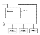
一般的に各家庭には図11に示すように、ガス供給ラインの入り口にガスの流量計を内蔵したガスメータ16が取り付けられている。
Generally, as shown in FIG. 11, a
現状多くのガスメータ16にはガス流量の計測という基本的な機能に付加して、異常時発生時にはガス供給を遮断する保安機能を有している。例えば、地震に対しては感震器を内蔵し、振動を検知し、ガスを遮断する。またガスの漏洩に対しては、ある所定量で所定時間以上ガスが流れている場合異常と見なしてガスを遮断する仕組みを有している。
At present,
しかしながらこの保安機能をさらに進化させるためには、使用器具の判別を行い、器具に応じた遮断条件を設定してやる必要があり、以下のような提案がなされている。すなわち計測されるガス流量に応じて、その流量変化から、使用されているガス器具を類推するアルゴリズムを提唱するものである。
しかしながら、前記従来の構成では、ガスメータ16の重要な機能である保安機能において、ガス流量の発生が検出されたのち、ガスが継続して使用された際、使用継続時間が長い場合、ガス漏れなどの異常事態を想定して一定時間でガスを遮断するようになっているが、器具の使用状態を判別しての判断でなく、ガス流量が大きい場合には時間を短く、暖房のようなガス使用量が少ない場合の想定では、時間を長く設定し対応している。
However, in the conventional configuration, in the security function, which is an important function of the
しかしながら、使用器具を特定していないので、ガス流量に対する遮断時間の設定では、例えばガス流量が暖房器具と同程度のコンロなどに対しては、安全機能としての役割が不十分であり、使用のガス器具に応じて保安することは従来構成においては難しい。 However, since the appliance used is not specified, the setting of the shut-off time for the gas flow rate does not have a sufficient role as a safety function for, for example, a stove with a gas flow rate similar to that of a heating appliance. It is difficult to secure in accordance with the gas appliance in the conventional configuration.
またこの問題に対して、これまでガスメータ16が検出するガス流量から、使用中のガス器具を判定するため、ガスメータ16の流量変化認識手段からの情報により推論によるガス器具判別が提案されているが、その判別ロジックは極めて曖昧であり、高い精度で使用中のガス器具を判定することは難しく、高度な保安機能や最適なサービスの提供に利用することは困難であった。
Moreover, in order to determine the gas appliance in use from the gas flow rate detected by the
本発明は、前記従来の課題を解決するもので、使用器具を特定でき、使用ガス器具に応じた保安機能を有するガスメータを提供することを目的とする。 The present invention solves the above-described conventional problems, and an object of the present invention is to provide a gas meter that can identify a tool to be used and has a security function according to the gas tool to be used.
前記従来の課題を解決するために、本発明のガスメータは家庭用ガス供給管に接続され、ガス流量を計測する流量計測手段に加え、器具情報入力手段と器具情報入力手段により登録されたデータを記憶する登録記憶手段と登録記憶手段のデータをもとにガス流量計測手段で計測されるガス流量値と比較し、使用ガス器具を判断する器具判定手段を有する構成である。 In order to solve the above-mentioned conventional problems, the gas meter of the present invention is connected to a household gas supply pipe, and in addition to the flow rate measuring means for measuring the gas flow rate, the data registered by the appliance information input means and the appliance information input means The apparatus has a registration storage means for storing and an appliance determination means for comparing the gas flow rate value measured by the gas flow rate measurement means based on the data stored in the registration storage means to determine the gas appliance to be used.
本発明のガスメータは、各家毎個別に、ガスメータにその家にあるガス器具の登録を行う構成とし、登録するデータとして各機器に特徴的な流量パターンを登録するため、判定する機器の数が個々の家庭内の登録機器に限られ比較するデータ数が少なくなると共に、判定基準となる各機器の流量パターンを比較基準データとして記憶させるため、器具判別の信頼性が向上し、器具判別が簡単なアルゴリズムで高い判定能力をもつことが可能となり、使用器具に対応した保安設定値を最適に変更することや、使用機器に対応したガス料金の設定など、新たなサービスの提供を可能とする。 The gas meter of the present invention has a configuration in which the gas appliances in the house are registered in the gas meter individually for each house, and a characteristic flow rate pattern is registered in each apparatus as data to be registered. The number of data to be compared is limited to each registered device in each home, and the flow rate pattern of each device that is a criterion is stored as comparison standard data, improving the reliability of instrument discrimination and simplifying instrument discrimination It is possible to have a high judgment capability with a simple algorithm, and it is possible to provide new services such as optimally changing the security setting value corresponding to the appliance used and setting the gas charge corresponding to the appliance used.
第1の発明は、家庭用ガス供給管に接続され、ガス流量を計測する流量計測手段とガス器具の情報入力手段と情報入力手段により登録されたデータを記憶する登録記憶手段と登録記憶手段のデータをもとに流量計測手段で計測されるガス流量値と比較し、使用ガス器具を判断する器具判定手段を有するガスメータであって、各家毎個別に、その家にあるガス器具の登録を行う構成するので、器具判別の信頼性が向上し、器具判別が簡単なアルゴリズムで高い判定能力をもたせることが可能となる。 According to a first aspect of the present invention, there is provided a flow rate measuring means for measuring a gas flow rate, an information input means for a gas appliance, a registration storage means for storing data registered by the information input means, and a registration storage means. This is a gas meter that has an appliance judgment means that compares the gas flow rate measured by the flow rate measurement means based on the data and judges the gas appliance to be used, and registers each gas appliance in that house individually. Since it is configured to perform, the reliability of appliance discrimination is improved, and it is possible to provide high judgment capability with an algorithm that makes appliance discrimination simple.
第2の発明は、特に、第1の発明において、登録された各ガス器具の使用履歴を記録する履歴記憶手段を備えるガスメータであって、各ガス器具別使用量と使用時間がリアルタイムまたは事後においても把握でき、器具別料金の新設や器具別の保安条件の設定がより細かく設定が可能になり、消費者に新しいサービスの提供が可能となる。 In particular, the second invention is a gas meter comprising history storage means for recording the usage history of each registered gas appliance in the first invention, wherein the usage amount and usage time for each gas appliance are in real time or after the fact. As a result, it is possible to set up a new fee for each appliance and to set the security conditions for each appliance more precisely, and to provide new services to consumers.
第3の発明は、特に、第2の発明において、履歴記憶手段のデータと流量計測手段で計測されるガス流量値と比較し、判別された器具使用の終了を判別することを可能とし、より器具判別機能の充実及び新サービスの提供を図れるものである。 The third invention, in particular, in the second invention, makes it possible to compare the data of the history storage means and the gas flow rate value measured by the flow rate measurement means, and to determine the end of the use of the determined instrument. It is possible to enhance the equipment discrimination function and provide new services.
第4の発明は、特に、第1〜3のいずれか1項の発明の情報入力手段の入力として設置器具の流量パターンを登録する構成であって、登録された流量パターンと実際に計測されるガス流量値の変化を比較し、どの器具が使用されているかを判断するため、誤認少なく使用されている器具の判別を行うことができる。 In particular, the fourth invention is a configuration for registering the flow pattern of the installation tool as an input of the information input means according to any one of the first to third inventions, and is actually measured with the registered flow pattern. Since the change of the gas flow rate value is compared to determine which instrument is being used, it is possible to determine which instrument is being used with little misunderstanding.
第5の発明は、特に、第1〜3のいずれか1つの発明においてガスメータは、ガス器具個々に付された認識コードとその認識コードに対応するガス器具の流量パターンをデータとして記録されている登録記憶手段を有し、設置器具の登録においては、その器具に対応した認識コードを入力(登録)することで計測されるガス流量値変化と認識コードに対応したガス流量パターンの比較により使用されているガス器具の判別を行うことにより、誤認少なく器具判別を行うことができる。 In the fifth aspect of the invention, in particular, in any one of the first to third aspects of the invention, the gas meter records the identification code assigned to each gas appliance and the flow rate pattern of the gas appliance corresponding to the recognition code as data. It has a registration storage means, and is used for registering the installed instrument by comparing the gas flow rate value measured by inputting (registering) the recognition code corresponding to the instrument and the gas flow pattern corresponding to the recognition code. By discriminating the gas appliances that are present, it is possible to discriminate the appliances with little misunderstanding.
第6の発明は、特に、第1〜3のいずれか1項の発明の情報入力手段において、設置された器具に対応した認識コードを入力することにより、その認識コードに対応した流量パターンを情報入力手段と接続された外部情報データベースからガスメータ内の登録記憶手段にデータをダウンロードする構成とすることにより、ガスメータ自身が市場にあるすべての器具の流量パターンを記憶・保持する必要が無く、また流量パターンを一括管理できるため、データの更新や修正も容易である。 In the sixth aspect of the invention, in particular, in the information input means of any one of the first to third aspects of the invention, by inputting the recognition code corresponding to the installed instrument, the flow rate pattern corresponding to the recognition code is information. By adopting a configuration that downloads data from the external information database connected to the input means to the registration storage means in the gas meter, the gas meter itself does not need to store and hold the flow patterns of all instruments on the market, and the flow rate Since patterns can be managed collectively, data can be easily updated and modified.
第7の発明は、特に、第4〜6のいずれか1つの発明の器具情報入力手段における入力情報で各ガス器具の流量パターンにおいて、器具の制御仕様など特徴的な流量変化のデータを抽出選択して器具判別情報データとすることで、より器具判別精度の向上を図ることができる。 In the seventh aspect of the invention, in particular, the input information in the instrument information input means of any one of the fourth to sixth aspects is used to extract and select characteristic flow rate change data such as instrument control specifications in the flow pattern of each gas instrument. By using the appliance discrimination information data, the appliance discrimination accuracy can be further improved.
第8の発明は、特に、第1〜7いずれか1つの発明の登録記憶手段内のデータ情報の修正や削除を行う情報修正機能を有する情報入力手段とすることにより、使わなくなった器具の登録抹消や器具の不具合による修理や交換などによる登録設定情報の変化にも対応することが可能となる。 In the eighth aspect of the invention, in particular, registration of equipment that is no longer used by using information input means having an information correction function for correcting or deleting data information in the registration storage means of any one of the first to seventh aspects of the invention. It is also possible to cope with changes in registration setting information due to erasure or repair or replacement due to equipment failure.
第9の発明は、特に、第4〜8いずれか1つの発明の登録記憶手段において登録された流量パターンと判別手段により判別され流量計測手段により計測される流量値の変化との比較において個体差、経年変化などにより、その入力データと実際の流量変化値の差が所定以上になると、データ補正を行う機能を有し、登録されているデータを実計測データで補正することで、常に器具判別の精度を高く維持することが可能となる。 In particular, the ninth invention relates to individual differences in the comparison between the flow rate pattern registered in the registration storage means of any one of the fourth to eighth inventions and the change in flow rate value determined by the determination means and measured by the flow measurement means. When the difference between the input data and the actual flow rate change value exceeds a predetermined value due to aging, etc., it has a function to correct the data and always corrects the instrument by correcting the registered data with the actual measurement data. It is possible to maintain a high accuracy.
第10の発明は、特に、第1〜9いずれか1つの発明の流量計測手段において、超音波による計測構成とすることで、流量値の計測範囲も広く、かつ瞬時流量計測も可能であるため、より正確な流量計測が行え、器具判別に対する信頼性向上も図るガスメータを構成することが可能となる。 In the tenth aspect of the invention, in particular, in the flow rate measuring means according to any one of the first to ninth aspects, the measurement configuration using ultrasonic waves enables a wide flow rate measurement range and instantaneous flow rate measurement. Thus, it is possible to configure a gas meter that can perform more accurate flow rate measurement and improve the reliability of instrument discrimination.
(実施の形態1)
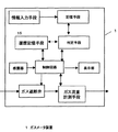
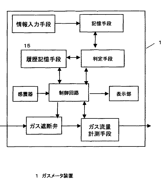
図1は、本発明の実施の形態1におけるガスメータの概略構成図を示すものである。
(Embodiment 1)
FIG. 1 is a schematic configuration diagram of a gas meter according to
図1において、1はガスメータであり、ガス供給管の途中に設けられ、その下流側の配管には各顧客宅内に設置された1台以上のガス器具が接続されている。
In FIG. 1,
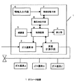
ガスメータ内部はガス管に接続されたガスの流路内に設けられたガス遮断弁2とガス流量計測手段3とガス流量計測手段3からの信号を演算処理して使用ガス流量を表示する表示部4、また地震などの振動を検出する感震器5、及び本発明に係わるガス器具判別を行うため、情報入力手段6、登録記憶手段7及び器具判定手段8と感震器の作動や器具判断、保安機能その他を統括制御処理する制御回路9及びそれらの動力源となる電池(図示せず)を内蔵している。
The inside of the gas meter is a display unit that displays the gas flow rate used by arithmetically processing signals from the gas shut-off
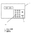
情報入力手段6としては、ガスメータ1本体に内蔵されていても外部からの接続形態でもかまわない。本発明においては、図2に示すように数値及び記号等が入力できる入力キー10列及び外部機器との接続手段11を有している。なお、通常はこの入力キー10部にはカバー(図示せず)がされており、不用意に操作できないようになっている。
The information input means 6 may be built in the main body of the
登録記憶手段7は、登録されたデータを記憶保持する半導体メモリまたは、記録の追加、書き換えができるものであれば、磁気記録媒体その他でも可能である。 The registration storage means 7 can be a semiconductor memory that stores registered data, or a magnetic recording medium or the like as long as it can add or rewrite recording.
器具判定手段8は、登録データと計測流量値より使用ガス器具を判定するものであるがその動作については後述する。 The appliance determination means 8 determines the gas appliance to be used from the registered data and the measured flow rate value, and the operation will be described later.
なお、本発明の流量計測手段3に関しては、超音波方式の計測部を有しているが、計測方式としては、他の流量計測方式でも短時間のサイクルで連続計測可能であれば使用可能である。 Although the flow rate measuring means 3 of the present invention has an ultrasonic measurement unit, other measurement methods can be used as long as they can be continuously measured in a short cycle. is there.
以下、動作について説明する。 The operation will be described below.
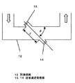
まず超音波方式の流速計測に関して図3をもとに説明する。計測流路12は矩形断面を持っており、計測流路12のガスの流れる方向と直角方向にある壁面には計測流路12を挟んで一対の超音波送受信器13、14が計測流路12の上流側と下流側で角度φを有して斜めに対向して装着されている。超音波送受信器13、14間で交互に超音波を送受信させて流体の流れに対して順方向と逆方向の超音波の伝搬時間の差を一定間隔を置いて計り、伝搬時間差信号として出力する働きを持つ。この伝搬時間差信号を受けて演算手段(図示せず)により被計測流体の流速及び流量を算出するものである。
First, the ultrasonic flow velocity measurement will be described with reference to FIG. The
演算式を下記に示す。 The calculation formula is shown below.
図3においてLは測定距離であり、t1を上流からの伝達時間、t2を下流からの伝達時間、Cを音速とすると、流速Vは
V=L/2cosφ(1/t1−1/t2) (1)
計測の時間間隔は超音波の送受信が可能な範囲で設定できるが、器具判別を行うためには0.1秒の分解能があれば充分である。
In FIG. 3, L is a measurement distance, where t1 is the transmission time from the upstream, t2 is the transmission time from the downstream, and C is the speed of sound, the flow velocity V is V = L / 2cosφ (1 / t1-1 / t2) ( 1)
The measurement time interval can be set within a range where ultrasonic waves can be transmitted / received, but a resolution of 0.1 second is sufficient to perform instrument discrimination.
次に器具登録を行う手順について説明する。その流れ図を図4に示す。 Next, a procedure for performing device registration will be described. The flowchart is shown in FIG.
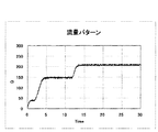
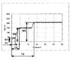
ガスメータ1に登録する情報としては、上記したように各ガス機器の使用時に発生する流量パターンを用いる(ステップ1)。図5にその一例を示す。実際の登録データとしては、器具スタート時から0.2秒毎の流量値のデータを所定時間分記憶したものである。なお、データの時間間隔としては0.2秒に限定する必要はなく、要求される器具判別能力により任意に設定できるものである。
As information to be registered in the
流量パターンの登録方法は、ガスメータ1の記憶手段には予め各ガス機器の流量パターンとそれに対応するコードナンバーを保持記憶している(ステップ2)。
In the flow rate pattern registration method, the storage unit of the
情報入力手段6の入力キー10から設置する器具のコードナンバーが登録必要数分だけ入力され登録記憶手段7に記憶される。
The code numbers of the appliances to be installed are inputted from the
ガスメータ1では一定間隔毎にガス流量を計測し、新たに計測されたガス流量値が直前の値から所定値以上増加すると、新たな器具が使用されたと判断し(ステップ3)、その流量変化と登録記憶手段に登録された器具のコードに対応する流量パターンと比較を行い(ステップ4,5)、使用されている器具の判別を行う(ステップ6)。
The
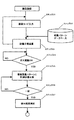
なお、図6に示すようにガスメータ1に履歴記憶手段15を有し、ガス流量の測定値を時系列で保持記憶することにより、過去の推移と、新たに計測されたガス流量値を比較するため(ステップ11〜13)、より新たな器具が使用されたかどうかの判断の信頼性が向上する(ステップ14)。
As shown in FIG. 6, the
なお、図7の流れ図に示すように履歴記憶手段15に残されている器具使用前の流量データと現在の使用データとを比較し、ガス流量値が器具使用前の値に戻ったことを検知し(ステップ15)、使用終了判断の機能を有すことも可能である(ステップ16)。 In addition, as shown in the flowchart of FIG. 7, the flow rate data before use of the appliance remaining in the history storage means 15 is compared with the current use data, and it is detected that the gas flow rate value has returned to the value before use of the appliance. However, it is also possible to have a function for determining the end of use (step 16).
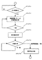
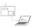
なお、流量パターンの登録方法としては、図8に示すようにガスメータ1と外部のデータベースとを接続し、図9に示すように、新規に登録するガス機器の認証コードをキー入力で登録すると(ステップ21)、データ登録手段によりその認証コードに対応した流量パターンがデータベースよりダウンロードされ(ステップ22)、登録記憶手段7に保存される(ステップ23)。そして、ガスメータ1では一定間隔毎にガス流量を計測し、新たに計測されたガス流量値が直前の値から所定値以上増加すると、新たな器具が使用されたと判断し(ステップ24)、その流量変化と登録記憶手段に登録された器具のコードに対応する流量パターンと比較を行い(ステップ25,26)、使用されている器具の判別を行うものである(ステップ27)。
As a flow rate pattern registration method, the
なお、この外部データとの接続形態は有線でなくても無線タイプのもの、あるいはデータが記憶されたメモリ部材を直接接続するようなものでも使用可能である。 Note that the connection form with the external data may be a wireless type, not a wired connection, or a direct connection with a memory member storing data.
なお、流量パターンは図10に示されるような、ある時間間隔のデータの差や最大値などの特徴的な数値を(表1)のようにテーブル化したものを使用し、実際に計測される流量値との比較でも使用可能である。 As shown in FIG. 10, the flow rate pattern is actually measured using characteristic numerical values such as a difference in data at a certain time interval and a maximum value in a table as shown in (Table 1). It can also be used in comparison with flow rate values.
また、登録記憶手段7内に登録されている登録データは、情報入力手段6によるキー操作により修正、削除することを可能とすることで、無駄なデータや、誤動作を起こす可能性のあるデータを排除でき、常に最適な判断データのガスメータ1内への構築ができ、またメモリの削減、消費電力の低減も行うことができる。
In addition, registration data registered in the registration storage means 7 can be corrected and deleted by a key operation by the information input means 6, so that useless data or data that may cause a malfunction is stored. Therefore, it is possible to always construct optimum judgment data in the
なお、初期に登録された流量パターンに対して、実使用状態での器具の流量変化のパターンに差がある場合や、経時変化により差が生じた場合、その差が所定値以上であると実際の流量値との差分分のデータを補正し、データの更新・補正を行う機能を制御手段が有することにより、器具判別の精度をより向上させることが可能となる。 Note that if there is a difference in the flow rate change pattern of the instrument in actual use with respect to the initially registered flow rate pattern, or if there is a difference due to changes over time, the difference is actually greater than or equal to the predetermined value. The control means has a function of correcting data corresponding to the difference from the flow rate value and updating / correcting the data, so that the accuracy of appliance discrimination can be further improved.
なお、履歴記憶手段15に保持されたデータを接続端子より外部に取り出し、そのデータをもとにガス料金の設定や機器の使用状態を把握して、効率よくガス器具を使えるようにマネイジメントサービスなど種々の利用方法が可能である。 The data stored in the history storage means 15 is taken out from the connection terminal, the gas charge settings and the usage state of the equipment are grasped based on the data, and the management service etc. so that the gas appliance can be used efficiently. Various utilization methods are possible.
以上のように、本発明にかかるガスメータは、登録するデータとして各機器に特徴的な流量パターンを登録するため、判定する機器の数が個々の家庭内の機器に限られ比較するデータとの数が少なくなると共に、判定基準となる各機器の流量パターンを登録するため、その信頼性も高くなり、器具判別が簡単なアルゴリズムで高い判定能力をもつことが可能となり、使用器具に対応した保安設定値を最適に変更することや、使用機器に対応したガス料金の設定など、新たなサービスの提供を可能とする。 As described above, since the gas meter according to the present invention registers a characteristic flow rate pattern for each device as data to be registered, the number of devices to be determined is limited to the devices in each home and the number of data to be compared. The flow rate pattern of each device, which is a criterion for judgment, is registered and the reliability is high, and it is possible to have a high judgment capability with a simple algorithm for appliance discrimination, and the security setting corresponding to the appliance used It will be possible to provide new services, such as changing values optimally and setting gas charges corresponding to the equipment used.
1 ガスメータ
2 ガス遮断弁
3 流量計測手段
4 表示部
5 感震器
6 情報入力手段
7 登録記憶手段
8 器具判定手段
9 制御回路
10 入力キー
11 接続手段
12 計測流路
13,14 超音波送受信器
15 履歴記憶手段
DESCRIPTION OF
Claims (10)
Priority Applications (1)
| Application Number | Priority Date | Filing Date | Title |
|---|---|---|---|
| JP2005012287A JP2006200802A (en) | 2005-01-20 | 2005-01-20 | Gas meter |
Applications Claiming Priority (1)
| Application Number | Priority Date | Filing Date | Title |
|---|---|---|---|
| JP2005012287A JP2006200802A (en) | 2005-01-20 | 2005-01-20 | Gas meter |
Publications (1)
| Publication Number | Publication Date |
|---|---|
| JP2006200802A true JP2006200802A (en) | 2006-08-03 |
Family
ID=36958965
Family Applications (1)
| Application Number | Title | Priority Date | Filing Date |
|---|---|---|---|
| JP2005012287A Pending JP2006200802A (en) | 2005-01-20 | 2005-01-20 | Gas meter |
Country Status (1)
| Country | Link |
|---|---|
| JP (1) | JP2006200802A (en) |
Cited By (24)
| Publication number | Priority date | Publication date | Assignee | Title |
|---|---|---|---|---|
| JP2008101951A (en) * | 2006-10-17 | 2008-05-01 | Toshiba Corp | Gas appliance discrimination device and discrimination method |
| WO2008050490A1 (en) * | 2006-10-25 | 2008-05-02 | Panasonic Corporation | Flowmeter and its program |
| JP2008107270A (en) * | 2006-10-27 | 2008-05-08 | Matsushita Electric Ind Co Ltd | Flow measuring apparatus |
| JP2008107268A (en) * | 2006-10-27 | 2008-05-08 | Matsushita Electric Ind Co Ltd | Gas meter device |
| JP2008111676A (en) * | 2006-10-27 | 2008-05-15 | Toshiba Corp | Device, method and system for determining gas appliance, and device and method for monitoring gas flow channel |
| JP2008128700A (en) * | 2006-11-17 | 2008-06-05 | Matsushita Electric Ind Co Ltd | Flow measuring apparatus |
| JP2008139267A (en) * | 2006-12-05 | 2008-06-19 | Toshiba Corp | System and method for controlling supply of gas, district gas supply control device, and individual gas supply control device |
| JP2008151522A (en) * | 2006-12-14 | 2008-07-03 | Matsushita Electric Ind Co Ltd | Flowmeter and its program |
| JP2008170217A (en) * | 2007-01-10 | 2008-07-24 | Matsushita Electric Ind Co Ltd | Flow measuring apparatus |
| JP2008175705A (en) * | 2007-01-19 | 2008-07-31 | Matsushita Electric Ind Co Ltd | Flow rate measuring device |
| JP2008185484A (en) * | 2007-01-30 | 2008-08-14 | Yazaki Corp | Gas use information display |
| JP2008185485A (en) * | 2007-01-30 | 2008-08-14 | Yazaki Corp | Method and apparatus for registering gas flow rate pattern and gas appliance identification apparatus |
| JP2008202947A (en) * | 2007-02-16 | 2008-09-04 | Matsushita Electric Ind Co Ltd | Gas meter device |
| JP2008202948A (en) * | 2007-02-16 | 2008-09-04 | Matsushita Electric Ind Co Ltd | Gas meter device |
| JP2008224219A (en) * | 2007-03-08 | 2008-09-25 | Matsushita Electric Ind Co Ltd | Flow rate measurement device and gas supply system using the same |
| JP2008224279A (en) * | 2007-03-09 | 2008-09-25 | Matsushita Electric Ind Co Ltd | Gas appliance discrimination system and gas supply system |
| JP2009041914A (en) * | 2007-08-06 | 2009-02-26 | Panasonic Corp | Flow rate measurement apparatus and fluid supply system using the same |
| JP2009150750A (en) * | 2007-12-20 | 2009-07-09 | Panasonic Corp | Wireless apparatus for automatic meter-reading |
| JP2010039899A (en) * | 2008-08-07 | 2010-02-18 | Panasonic Corp | Gas shut-off device |
| JP2010203872A (en) * | 2009-03-03 | 2010-09-16 | Panasonic Corp | Flow rate measuring device |
| JP2010242996A (en) * | 2009-04-02 | 2010-10-28 | Panasonic Corp | Gas shut-off device |
| JP2012132632A (en) * | 2010-12-22 | 2012-07-12 | High Pressure Gas Safety Institute Of Japan | Gas shut-off device |
| WO2013157257A1 (en) | 2012-04-17 | 2013-10-24 | パナソニック株式会社 | Flow rate measurement device |
| JP2013221852A (en) * | 2012-04-17 | 2013-10-28 | Panasonic Corp | Flow rate measurement device |
-
2005
- 2005-01-20 JP JP2005012287A patent/JP2006200802A/en active Pending
Cited By (28)
| Publication number | Priority date | Publication date | Assignee | Title |
|---|---|---|---|---|
| JP2008101951A (en) * | 2006-10-17 | 2008-05-01 | Toshiba Corp | Gas appliance discrimination device and discrimination method |
| CN102116646A (en) * | 2006-10-25 | 2011-07-06 | 松下电器产业株式会社 | Flow measurement instrument |
| WO2008050490A1 (en) * | 2006-10-25 | 2008-05-02 | Panasonic Corporation | Flowmeter and its program |
| US8515692B2 (en) | 2006-10-25 | 2013-08-20 | Panasonic Corporation | Flow rate measuring apparatus and program thereof |
| JP2008107270A (en) * | 2006-10-27 | 2008-05-08 | Matsushita Electric Ind Co Ltd | Flow measuring apparatus |
| JP2008107268A (en) * | 2006-10-27 | 2008-05-08 | Matsushita Electric Ind Co Ltd | Gas meter device |
| JP2008111676A (en) * | 2006-10-27 | 2008-05-15 | Toshiba Corp | Device, method and system for determining gas appliance, and device and method for monitoring gas flow channel |
| JP2008128700A (en) * | 2006-11-17 | 2008-06-05 | Matsushita Electric Ind Co Ltd | Flow measuring apparatus |
| JP2008139267A (en) * | 2006-12-05 | 2008-06-19 | Toshiba Corp | System and method for controlling supply of gas, district gas supply control device, and individual gas supply control device |
| JP2008151522A (en) * | 2006-12-14 | 2008-07-03 | Matsushita Electric Ind Co Ltd | Flowmeter and its program |
| JP2008170217A (en) * | 2007-01-10 | 2008-07-24 | Matsushita Electric Ind Co Ltd | Flow measuring apparatus |
| JP2008175705A (en) * | 2007-01-19 | 2008-07-31 | Matsushita Electric Ind Co Ltd | Flow rate measuring device |
| JP2008185485A (en) * | 2007-01-30 | 2008-08-14 | Yazaki Corp | Method and apparatus for registering gas flow rate pattern and gas appliance identification apparatus |
| JP2008185484A (en) * | 2007-01-30 | 2008-08-14 | Yazaki Corp | Gas use information display |
| JP2008202947A (en) * | 2007-02-16 | 2008-09-04 | Matsushita Electric Ind Co Ltd | Gas meter device |
| JP2008202948A (en) * | 2007-02-16 | 2008-09-04 | Matsushita Electric Ind Co Ltd | Gas meter device |
| JP2008224219A (en) * | 2007-03-08 | 2008-09-25 | Matsushita Electric Ind Co Ltd | Flow rate measurement device and gas supply system using the same |
| JP2008224279A (en) * | 2007-03-09 | 2008-09-25 | Matsushita Electric Ind Co Ltd | Gas appliance discrimination system and gas supply system |
| JP2009041914A (en) * | 2007-08-06 | 2009-02-26 | Panasonic Corp | Flow rate measurement apparatus and fluid supply system using the same |
| JP2009150750A (en) * | 2007-12-20 | 2009-07-09 | Panasonic Corp | Wireless apparatus for automatic meter-reading |
| JP2010039899A (en) * | 2008-08-07 | 2010-02-18 | Panasonic Corp | Gas shut-off device |
| JP2010203872A (en) * | 2009-03-03 | 2010-09-16 | Panasonic Corp | Flow rate measuring device |
| JP2010242996A (en) * | 2009-04-02 | 2010-10-28 | Panasonic Corp | Gas shut-off device |
| JP2012132632A (en) * | 2010-12-22 | 2012-07-12 | High Pressure Gas Safety Institute Of Japan | Gas shut-off device |
| WO2013157257A1 (en) | 2012-04-17 | 2013-10-24 | パナソニック株式会社 | Flow rate measurement device |
| JP2013221853A (en) * | 2012-04-17 | 2013-10-28 | Panasonic Corp | Flow rate measurement device |
| JP2013221852A (en) * | 2012-04-17 | 2013-10-28 | Panasonic Corp | Flow rate measurement device |
| CN104246453A (en) * | 2012-04-17 | 2014-12-24 | 松下知识产权经营株式会社 | Flow rate measurement device |
Similar Documents
| Publication | Publication Date | Title |
|---|---|---|
| JP2006200802A (en) | Gas meter | |
| JP5094374B2 (en) | Flow measurement device and gas supply system | |
| JP4935334B2 (en) | Flow rate measuring device and gas supply system using this device | |
| JP4729971B2 (en) | Gas meter device | |
| KR100937076B1 (en) | Flow rate measurement device | |
| JP4581882B2 (en) | Flow measuring device | |
| JP2007024750A (en) | Flow measuring instrument | |
| JP5092723B2 (en) | Flow measuring device | |
| JP2007199002A (en) | Gas appliance discriminating device | |
| JP5288600B2 (en) | Gas shut-off device | |
| JP5109636B2 (en) | Flow rate measuring device and gas supply system using the same | |
| JP2008202947A (en) | Gas meter device | |
| JP5076506B2 (en) | Flow measuring device and program thereof | |
| JP5259297B2 (en) | Gas shut-off device | |
| JP5103865B2 (en) | Gas meter device | |
| JP5162898B2 (en) | Flow measurement device and gas supply system | |
| JP4341605B2 (en) | Instrument information display system | |
| JP4862698B2 (en) | Flow rate measuring device and gas supply system using this device | |
| JP5070849B2 (en) | Flow measuring device | |
| JP2010181356A (en) | Flow measuring device | |
| JP2010107208A (en) | Flow measuring device | |
| JP5310253B2 (en) | Instrument discrimination gas meter system | |
| JP2010160003A (en) | Gas meter | |
| JP5131976B2 (en) | Flow measuring device | |
| JP5169370B2 (en) | Flow measuring device and program thereof |
Legal Events
| Date | Code | Title | Description |
|---|---|---|---|
| A621 | Written request for application examination |
Free format text: JAPANESE INTERMEDIATE CODE: A621 Effective date: 20071220 |
|
| RD01 | Notification of change of attorney |
Effective date: 20080115 Free format text: JAPANESE INTERMEDIATE CODE: A7421 |
|
| A977 | Report on retrieval |
Effective date: 20081010 Free format text: JAPANESE INTERMEDIATE CODE: A971007 |
|
| A131 | Notification of reasons for refusal |
Free format text: JAPANESE INTERMEDIATE CODE: A131 Effective date: 20081021 |
|
| A02 | Decision of refusal |
Effective date: 20090303 Free format text: JAPANESE INTERMEDIATE CODE: A02 |