WO2013153809A1 - 撮像装置およびその制御方法 - Google Patents
撮像装置およびその制御方法 Download PDFInfo
- Publication number
- WO2013153809A1 WO2013153809A1 PCT/JP2013/002444 JP2013002444W WO2013153809A1 WO 2013153809 A1 WO2013153809 A1 WO 2013153809A1 JP 2013002444 W JP2013002444 W JP 2013002444W WO 2013153809 A1 WO2013153809 A1 WO 2013153809A1
- Authority
- WO
- WIPO (PCT)
- Prior art keywords
- color space
- signal
- image
- image signal
- conversion
- Prior art date
- Legal status (The legal status is an assumption and is not a legal conclusion. Google has not performed a legal analysis and makes no representation as to the accuracy of the status listed.)
- Ceased
Links
Images



Classifications
-
- H—ELECTRICITY
- H04—ELECTRIC COMMUNICATION TECHNIQUE
- H04N—PICTORIAL COMMUNICATION, e.g. TELEVISION
- H04N23/00—Cameras or camera modules comprising electronic image sensors; Control thereof
- H04N23/60—Control of cameras or camera modules
- H04N23/667—Camera operation mode switching, e.g. between still and video, sport and normal or high- and low-resolution modes
-
- H—ELECTRICITY
- H04—ELECTRIC COMMUNICATION TECHNIQUE
- H04N—PICTORIAL COMMUNICATION, e.g. TELEVISION
- H04N23/00—Cameras or camera modules comprising electronic image sensors; Control thereof
- H04N23/80—Camera processing pipelines; Components thereof
- H04N23/84—Camera processing pipelines; Components thereof for processing colour signals
-
- H—ELECTRICITY
- H04—ELECTRIC COMMUNICATION TECHNIQUE
- H04N—PICTORIAL COMMUNICATION, e.g. TELEVISION
- H04N23/00—Cameras or camera modules comprising electronic image sensors; Control thereof
- H04N23/80—Camera processing pipelines; Components thereof
- H04N23/84—Camera processing pipelines; Components thereof for processing colour signals
- H04N23/85—Camera processing pipelines; Components thereof for processing colour signals for matrixing
-
- H—ELECTRICITY
- H04—ELECTRIC COMMUNICATION TECHNIQUE
- H04N—PICTORIAL COMMUNICATION, e.g. TELEVISION
- H04N23/00—Cameras or camera modules comprising electronic image sensors; Control thereof
- H04N23/80—Camera processing pipelines; Components thereof
- H04N23/84—Camera processing pipelines; Components thereof for processing colour signals
- H04N23/88—Camera processing pipelines; Components thereof for processing colour signals for colour balance, e.g. white-balance circuits or colour temperature control
Definitions
- the present invention relates to an imaging apparatus and a control method thereof.
- a video camera and a still camera are different in many respects, and the former is a device that captures only a moving image, and the latter is a device that captures only a still image.
- both are now using an imaging device, also it became an image to digital processing, the difference between getting smaller.
- the still image shooting function with a video camera and the movie shooting function with a still camera have greatly improved from the original level. For example, even a small still camera built in a mobile phone can shoot a movie with full high-definition resolution. As much as possible.
- JPEG Joint Photographic Experts Group
- SD standard definition
- ITU-R Radio Communication Department of International Telecommunication Union
- BT Since the color space defined in the 601 standard (hereinafter simply referred to as BT.601 color space) is employed, the internal processing of a digital still camera is usually performed using BT. An image signal in the 601 color space is assumed. Even when shooting HD movies, BT. Before processing the image signal in the 601 color space and performing recording or external output, BT. 709 color space. This is because when still image shooting (or still image generation from a moving image) during moving image shooting is performed, it is necessary to match the colors of the obtained still image and moving image.
- the color space defined in the 709 standard is intended for the RGB to YUV color conversion matrix coefficients defined in each standard, and is not a primary (color gamut) or gamma according to the color standard.
- the color space conversion is an arithmetic process, and if it is repeatedly performed, image quality deterioration due to an operation error is assumed. Therefore, it is desirable that the number of conversions of the applied color space is small.
- BT. 709 color space signals are converted. In this case, the image signal, conversion of at least twice the color space to be recorded is to be applied from the output from the image sensor.
- the present invention provides an image pickup apparatus and its control method capable of suppressing image quality degradation of moving images due to the color space conversion processing is repeatedly applied.
- a first conversion unit that converts an image signal output from an image sensor into an image signal in a first color space, and color processing for the image signal in the first color space Is a signal processing means for outputting video signals, and a recording signal generating means for generating an image signal for moving image recording from an image signal output by the signal processing means, and is a second required for the image signal for moving image recording.
- a recording signal generating means having a second conversion means for converting an image signal output from the signal processing means into a signal of the second color space when the color space of the recording medium is different from the first color space;
- Display signal generation means for generating an image signal for display on the display device from the image signal output from the processing means, wherein the third color space required for the display image signal is the first color space. If they are different, the image signal output by the signal processing means
- Display signal generation means having a third conversion means for converting into a signal of the third color space, and control means for controlling the operation of the first to third conversion means. Control the operation of the first to third conversion means so that the number of color space conversion processes applied in the process of generating an image signal to be used for one of recording and display should be minimized.
- the first conversion means for converting the image signal output from the image sensor into the image signal in the first color space, and the color for the image signal in the first color space.
- Signal processing means for applying and outputting the processing, and recording signal generating means for generating an image signal for moving image recording from the image signal output by the signal processing means, which is required for the image signal for moving image recording
- a recording signal generating means having a second conversion means for converting an image signal output from the signal processing means into a signal in the second color space when the second color space is different from the first color space;
- Display signal generating means for generating an image signal for display on a display device from an image signal output from the signal processing means, wherein the third color space required for the display image signal is the first color space.
- An image pickup apparatus control method comprising: a display signal generation unit including a third conversion unit configured to convert a signal into a signal of a third color space, and an image used as one of priority for moving image recording and display Control of an imaging apparatus comprising a control step of controlling the operation of the first to third conversion means so that the number of color space conversion processes applied in the process of generating a signal is minimized.
- the imaging apparatus and the control method thereof according to the present invention it is possible to suppress deterioration in the image quality of a moving image due to repeated application of color space conversion processing.
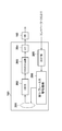
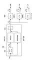
- FIG. 1 is a block diagram illustrating a configuration example of a digital still camera as an example of an imaging apparatus according to an embodiment of the present invention.
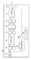
- the block diagram which shows the detail of the imaging part in FIG. The block diagram which shows the detail of the image processing part in FIG.
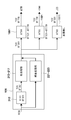
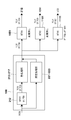
- the figure which shows the flow of the conventional color space conversion process typically The figure which shows typically the flow of the color space conversion process in embodiment of this invention.
- FIG. 1 is a block diagram illustrating a configuration example related to imaging, development, and output in a digital still camera 100 (hereinafter simply referred to as a digital camera) as an example of an imaging apparatus according to an embodiment of the present invention.
- the controller 130 includes a CPU and a memory such as a ROM and a RAM, and controls each part described below and implements some or all of the functions of each part. Note that at least a part of the configuration described below may be realized by software by the CPU of the controller 130, may be realized by hardware, or may be realized by cooperation of hardware and software. Good.
- the imaging unit 101 includes an imaging optical system and an imaging element, converts an optical image formed on the imaging surface of the imaging element into an electrical signal, converts the acquired electrical signal into a digital signal, and outputs the digital signal.
- a configuration example of the imaging unit 101 is shown in FIG. 2A.
- a subject image in the field of view (imaging range) of the photographic optical system 201 is imaged on the imaging surface of a CMOS 202 as an imaging element by the photographic optical system 201.
- the imaging element is not limited to a CMOS, and may be another photoelectric conversion element such as a CCD.
- the CDS / AGC circuit 203 performs correlated double sampling / gain adjustment on the electrical signal obtained from the CMOS 202.
- the A / D converter 204 digitally converts the signal output from the CDS / AGC circuit 203 and outputs it as an image signal.
- the photographing optical system 201 has a diaphragm and focus lens drive mechanism 206, and the AE / AF unit 205 controls the drive mechanism 206 in accordance with an instruction from the controller 130.
- Such an AE / AF unit 205 and drive mechanism 206 realize an automatic focus detection (AF) function and an automatic exposure control (AE) function.
- the WB circuit 102 performs white balance adjustment on the image signal output from the imaging unit 101 (A / D converter 204).
- the image signal whose white balance has been adjusted in the WB circuit 102 is supplied to the image processing unit 106. Detailed operation of the image processing unit 106 will be described later.
- the operation unit 103 is an input device group such as a switch, a button, a key, a dial, and a touch panel for a user to input various settings and instructions to the digital camera 100. Note that the operation unit 103 may use not only a physical mechanism operation but also eye gaze detection or voice recognition. Representative items included in the operation unit 103 are a release button, a menu display button, an arrow key, a determination / execution button, a shooting mode setting dial, and the like.
- Operation of the operation unit 103 is detected by the controller 130, the controller 130 controls each unit so as to realize the operation corresponding to the operation content detected.
- the controller 130 displays a GUI screen such as a menu screen on the display unit 111, or displays the setting information or shooting information of the digital camera 100 on the display image output from the image processing unit 106 and displays it on the display unit 111. To do.
- FIG. 2B is a diagram illustrating a detailed functional configuration example of the image processing unit 106.
- a noise removal unit (NR) 211 performs noise removal on the image signal that has been subjected to white balance adjustment.
- the image signal output from the noise removing unit 211 is processed in parallel with the color signal and the luminance signal.
- the first matrix (MTX) 212 converts the image signal (RGB) output from the noise removal unit 211 into a YUV signal in a predetermined first color space.
- RGB format image signal is expressed as BT. 601 color space and BT. It can be converted into a YUV (YCbCr) format image signal in the 709 color space.
- the first matrix 212 is BT. 601 color space and BT.
- the controller 130 sets which YUV signal in the 709 color space is to be converted.
- the first matrix 212 also performs matrix conversion that absorbs variations caused by the inherent spectral characteristics of the image sensor (CMOS) 202.
- CMOS image sensor
- the color suppression unit 213 adjusts (suppresses) the gain of the color value of the high luminance portion in order to maintain the white balance at the time of saturation.
- the second matrix 214 converts the YUV signal including the UV signal processed by the color suppression unit 213 into an RGB signal for ⁇ processing.
- the C ⁇ processing unit 215 performs ⁇ processing on the image signal (RGB signal) obtained by the second matrix 214.
- the third matrix 216 converts the output (RGB signal) of the C ⁇ processing unit 215 into a YUV signal again.
- the knee correction unit 217 receives the UV signal of the YUV signals output from the third matrix 216, compresses the color space at high saturation, and stores the image signal in the target color space.
- the G component of the image signal (RGB) output from the noise removing unit 211 is input to a luminance processing unit composed of blocks 221 to 223.
- the adaptive processing unit 221 generates an Y signal by performing an adaptation process on the G signal in order to maintain the band.
- the Y ⁇ processing unit 222 performs ⁇ processing on the Y signal generated by the adaptive processing unit 221.
- the output of the adaptive processing unit 221 is also supplied to the sharpness unit 223.
- the sharpness unit 223 detects the amount of sharpness from the input Y signal, and adds this to the output of the Y ⁇ processing unit 222.
- the controller 130 uses gamma characteristics (input / output characteristics) used for the C ⁇ processing unit 215 and the Y ⁇ processing unit 222.
- gamma characteristics input / output characteristics
- the recording moving image dedicated shooting mode is set.
- the recording video-specific imaging mode as the imaging mode is applied automatically in the above-mentioned Log gamma conversion.
- the output signal (U, V) of the knee correction unit 217 and the signal (Y) obtained from the luminance processing unit are supplied to a first look-up table (hereinafter referred to as a first LUT) 218, and the final signal from the image processing unit 106 is obtained.
- a YUV signal is generated and output.
- the color processing unit and the first LUT 218 constitute a signal processing unit.
- the recording unit 109 performs noise removal using, for example, correlation between frames of the input YUV signal. Thereafter, the recording unit 109 converts the image signal after noise removal into an image signal in the second color space as necessary by the fourth matrix 1091 to generate an image signal for moving image recording. Whether to convert the color space in the fourth matrix 1091, or perform any conversion when performing, the controller 130 sets. In addition, the recording unit 109 generates an image file according to a preset recording file format (for example, Exif: Exchangeable image file format) together with the additional information. Then, the image file is recorded on a recording medium such as a memory card or a hard disk.
- a preset recording file format for example, Exif: Exchangeable image file format
- the external output unit 110 generates an image signal for external output.
- the external output unit 110 generates a signal for external output via HDMI (High-Definition Multimedia Interface: registered trademark), but may generate a signal compliant with other standards.
- color space conversion processing is executed as necessary by the fifth matrix 1101. Whether to convert the color space in the fourth matrix 1101, or perform any conversion when performing, the controller 130 sets.
- the external output unit 110 may also perform resolution conversion as necessary. For example, when outputting from HDMI, it is converted to one of the resolutions defined by the HDMI standard (for example, 1920 ⁇ 1080 or 1280 ⁇ 720).
- the display unit 111 generates an image signal for display and displays it on a display device (in this example, an LCD provided on the back of the digital camera 100) of the digital camera 100.
- Display unit 111 converts so as to correspond to the resolution of the display device the resolution of the image, to apply the LUT to perform gradation correction if necessary.
- an LUT for simulating a state in which processing by gamma is performed so that the gradation becomes linear with respect to the visual characteristics is applied and displayed.
- Such an LUT is called a viewing LUT, and specifically, is an LUT having a characteristic of increasing the contrast of the intermediate luminance part suppressed by Log gamma as shown in FIG.
- a standard video color space for example, BT.709
- the viewing LUT is not applied when a gamma curve other than Log gamma is used. Further, a simulation may be performed by applying a gamma LUT corresponding to each environment.
- the display unit 111 converts the image signal into an image signal in the third color space as needed by the sixth matrix 1111. Whether to convert the color space in the sixth matrix 1111, or perform any conversion when performing, the controller 130 sets. Display unit 111 displays and supplied to the display device an image signal for display conversion LUT and the color space is applied as needed.
- FIG. 3 is a diagram schematically showing an extracted configuration related to the color space conversion process in the digital camera 100. Reference numerals are the same as those in FIGS. 1, 2A, and 2B.
- the RGB image signal is input from the imaging unit 101 to the image processing unit 106.
- the first matrix 212 converts RGB format image signals into BT.
- the image signal is converted into a YUV format image signal in a 601 color space.
- BT The conversion to the 601 color space is generally performed at the time of still image shooting in a digital camera.
- a still image is generally output as a JPEG file.
- the RGB-YUV matrix coefficient defined by JPEG is the same as the matrix coefficient defined by BT601.
- BT By performing the 601 conversion, matrix conversion is not required in the subsequent stage, so that the still image quality output as a JPEG file can be prioritized.
- BT After performing color processing, BT.
- the data is supplied to the recording unit 109, the external output unit 110, and the display unit 111 in the YUV format of the 601 color space.
- the fourth matrix 1091 of the recording unit 109 is BT. 601 color space YUV format image signal.
- the image signal is converted into a YUV format image signal in the 709 color space.
- An arithmetic expression for conversion to the 709 color space (or vice versa) can be obtained based on the mutual relationship of the conversion expressions from the RGB format described above to the YUV format in each color space.
- the BT. 601 color space YUV format image signal when outputting at HD resolution such as HDMI, the BT. 601 color space YUV format image signal.
- the image signal is converted into a YUV format image signal in the 709 color space.
- the display device of the digital camera 100 in this embodiment is BT. Since the image signal of the 601 color space is requested, the sixth matrix 1111 of the display unit 111 does not perform the color space conversion process, and the supplied BT. The 601 color space YUV format is supplied as it is to the subsequent stage.
- BT when shooting HD video, BT. After the YUV format image signal in the 601 color space, the BT. It is converted into a YUV format image signal in the 709 color space.
- FIG. Figure 4 is similar to FIG. 3, of the digital camera 100 is a diagram schematically showing an extracted configuration relating to the color space conversion processing. Reference numerals are the same as those in FIGS.
- the controller 130 sets the first matrix 212 to the BT. BT.601 which is equal to the color space required for the recording signal, not the YUV format of the 601 color space. It is set so that it is converted into a YUV format image signal in the 709 color space.
- BT. 709 color space image signal processing is executed.
- the controller 130 instructs the required block to switch the processing, or changes the setting values such as parameters.
- BT. BT.601 color space instead of YUV format.
- a YUV format image signal in the 709 color space is output.
- the controller 130 sets the fourth and fifth matrices 1101 and 1111 so as not to perform color space conversion. Therefore, the number of color space conversion processes to be applied to the image signal for moving image recording to be prioritized can be reduced to one time as compared to two in the case of FIG.
- the controller 130 stores the BT. 709 color space YUV format image signal. Settings are made so that the image signal is converted into a YUV format image signal in the 601 color space.
- the controller 130 determines whether or not use of Log gamma is set. For example, when the setting item 311 for using / not using Log gamma included in the Log gamma setting menu screen is selected and executed (determined) through the operation unit 103, the controller 130 determines that the use of Log gamma is set. .
- the controller 130 sets Log gamma as the gamma characteristic (input / output characteristic) used by the C ⁇ processing unit 215 and the Y ⁇ processing unit 222 in S103.
- the controller 130 stores the YUV format in the color space equal to the color space required for recording the moving image signal converted by the Log gamma in the first matrix 212 of the image processing unit 106.
- Set to convert to an image signal In this embodiment, the controller 130 converts an RGB format image signal into a BT.
- the first matrix 212 is set so as to convert the image signal into a YUV format image signal in the 709 color space.
- step S105 the controller 130 instructs the blocks 213 to 217 that perform color processing to change the processing contents when the color space is changed (changes the setting parameter).
- the controller 130 can store in advance a setting value for a component related to color space conversion processing or color processing in association with a settable gamma characteristic in a referable nonvolatile memory, for example. Then, when the set gamma characteristic is changed, the controller 130 can change the setting for the necessary functional block according to the changed gamma characteristic with reference to the nonvolatile memory.
- the controller 130 sets the recording unit 109 (fourth matrix 1091) and the external output unit 110 (fifth matrix 1101) so as not to perform color space conversion.
- the display unit 111 (6 matrix 1111), set to perform conversion into a color space required for the signal for display.
- the controller 130 is a BT. 709 color space YUV format image signal is converted to BT.
- the sixth matrix 1111 is set so as to convert it into a YUV format image signal in the 601 color space.
- an image in a color space equal to the color space required for the recording signal is used.
- Color processing and luminance processing were performed after conversion to a signal. Therefore, it is possible to reduce the number of color space conversion processes applied from the output from the image sensor to the recording to substantially one, and the moving image shooting function in the conventional digital still camera is used as it is. As compared with the case, the deterioration of the image quality can be reduced.
- the log gamma is 8-bit data, it is intentionally defined with a narrow dynamic range such as 16-254 in order to be optimized for movies and television. Therefore, in order to maintain high image quality, it is more effective to reduce the number of color conversions that may cause tone jumps.
- the gradation range of the pixels can be considered in the same way as this color space.
- the range is also converted to a different gradation range for movies and still images. Do not. If each is converted to a dedicated gradation range, it is performed by subsequent color conversion, and image quality deterioration is likely to occur.
- the present invention is not intended for conversion between these specific color spaces.
- the present invention can also be applied to conversion between the ACES (Academy Color Encoding Specification) standard color space proposed by the Academy of Motion Picture Arts and Sciences (AMPAS).
- ACES Academy Color Encoding Specification
- AMPAS Academy of Motion Picture Arts and Sciences
- an LMT (Look Modification Transform) file describing the contents of the image processing is associated with the image data or recorded in the image data.
- an LMT file may be generated in a CTL (Color Transform Language) format, which is a description language proposed by the Academy of Motion Picture Arts and Sciences (AMPAS).
- CTL is an interpreted language, and it is possible to apply image processing according to an instruction to an input image file while interpreting an instruction described in an LMT file.
- the image processing apparatus that has received the image data in which the LMT file is recorded can execute the image processing described in the set LMT file.
- the color space required for recording, external output, and display image signals is merely an example. Therefore, the color spaces required for recording and external output image signals are not always equal, and the present invention is not applicable only in such a case. Also, the three systems of recording, external output, and display are merely examples, and the number is not limited as long as there are a plurality of systems.
- the present invention provides an imaging apparatus that supplies moving image signals to a plurality of output destinations in order to adapt the contents of color space conversion processing before and after color processing and luminance processing to the color space required by the output destination to be prioritized. It is characterized in that it is determined so that the number of necessary color conversion processes is minimized. Specifically, priority is given to the number of color space conversion processes that are applied between the output from the image sensor and the image signal corresponding to the final output form (recording, external output, display, etc.). The image signal for the output form to be minimized is minimized. Therefore, when display should be prioritized over recording, the processing content of the color space conversion matrix is set so that the number of color space conversion processes applied in the process of generating a display image signal is minimized. . Further, the necessary color space conversion processing can be further suppressed as much as possible upstream of the processing (on the image sensor side), thereby further suppressing image quality degradation.
- the present invention is particularly effective at the time of moving image shooting applying Log gamma, but Log Gamma is applied as an effect of suppressing image quality deterioration by minimizing the number of times of color space conversion processing in a signal system where image quality should be prioritized. It is not limited at the time of video shooting.
- the present invention can also be realized by executing the following processing. That is, software (program) that realizes the functions of the above-described embodiments is supplied to a system or apparatus via a network or various storage media, and a computer (or CPU, MPU, or the like) of the system or apparatus reads the program. It is a process to be executed.
Landscapes
- Engineering & Computer Science (AREA)
- Multimedia (AREA)
- Signal Processing (AREA)
- Color Television Image Signal Generators (AREA)
- Processing Of Color Television Signals (AREA)
Description
本発明は、撮像装置およびその制御方法に関する。
従来、ビデオカメラとスチルカメラは多くの点で異なるものであり、前者は動画のみを、後者は静止画のみを撮影する装置であった。しかし、両者が撮像素子を用いるようになり、また画像をデジタル処理するようになったことで、両者の差は小さくなりつつある。現在、ビデオカメラによる静止画撮影機能や、スチルカメラにおける動画撮影機能は、当初のレベルから大幅に進歩し、例えば携帯電話に内蔵されるような小型のスチルカメラでも、フルハイビジョン解像度の動画撮影ができるほどである。
特に、近年、レンズ交換式デジタルスチルカメラにも動画撮影機能が搭載されるようになったことで、スチルカメラによる動画撮影が注目されている。これは、レンズ交換式デジタルスチルカメラが大型かつ画素数の多い撮像素子を用いていること、また、レンズ交換によって画角の変更が容易であること、高画質な静止画撮影が行えることなどによるものと考えられる。
映画やテレビのように、編集を前提とした撮影の場合、編集時の調整しろを確保するため、できるだけ白とびや黒つぶれが生じないよう、階調性を重視した記録が行われる。具体的には、輝度値の増加に対して対数的に(logarithmically)増加するような非線形な入出力特性を適用して記録することが知られている。このような非線形な入出力特性をLogまたはLogガンマと呼び、関数やテーブルとして定義される。さらに、定義されたLogガンマからさらに米国コダック社がフィルムスキャンデータの記録用に提唱したCineon LOG等で変換することによって写真フィルムの感光特性に近い画像データとして扱うことが可能になる。なお、Logガンマを適用することで、白とびや黒つぶれは抑制されて高い階調性が維持出来るが、記録した動画像は暗い部分が明るめに、明るい部分が暗めになったコントラストの低い画像となる。そのため、そのまま鑑賞するには適しておらず、最終的に人間の視覚特性に対して線形(リニア)な階調特性に変換する必要がある。
テレビや映画の制作においては、Logガンマの特性を有する動画像を編集することが一般的である。しかし、従来、デジタルスチルカメラによる動画撮影機能は、撮影後の編集処理(ポストプロダクション処理という)をしなくてもそのまま鑑賞するのに適した階調特性やコントラストを有する動画を記録するものであった。そのため、デジタルスチルカメラに対しても、Logガンマを用いた動画像記録への対応が要望されている。
Recommendation ITU-R BT.601-7 (03/2011) Studio encoding parameters of digital television for standard 4:3 and wide-screen 16:9 aspect ratios [平成24年4月9日検索]、インターネット<URL:http://www.itu.int/dms_pubrec/itu-r/rec/bt/R-REC-BT.601-7-201103-I!!PDF-E.pdf>
Recommendation ITU-R BT.709-5 (04/2002) Parameter values for the HDTV standards for production and international programme exchange [平成24年4月9日検索]、インターネット<URL:http://www.itu.int/dms_pubrec/itu-r/rec/bt/R-REC-BT.709-5-200204-I!!PDF-E.pdf>
画像信号には規格に応じて満たすべき色空間が規定されている。例えば静止画で一般的に用いられているJPEGや、標準解像度(SD)のテレビ、ビデオ信号についてはITU-R(国際電気通信連合の無線通信部門)によるBT.601規格で定められている(非特許文献1)。また、高解像度(HD)のテレビ、ビデオ信号については、ITU-RによるBT.709規格で定められている(非特許文献2)。
また、静止画記録においても、BT.601規格で定められた色空間(以下、単にBT.601色空間という)を採用しているため、通常、デジタルスチルカメラの内部処理は、BT.601色空間の画像信号を前提としている。そして、HD動画の撮影時においても、BT.601色空間で画像信号を処理し、記録や外部出力を行う前に、BT.709色空間へ変換している。これは、動画撮影中の静止画撮影(あるいは動画からの静止画生成)が行われた場合に、得られる静止画と動画との色を合わせる必要があるためである。ここでBT.601、BT.709規格で定められた色空間というのは、各規格で定義されたRGBからYUVへの色変換マトリクス係数を対象としており、カラー規格によるプライマリ(色域)やガンマではない。
しかしながら、色空間の変換は演算処理であり、繰り返し行うと演算誤差による画質劣化が想定されるため、適用される色空間の変換回数は少ない方が望ましい。しかしながら、Logガンマを適用したHD動画撮影を従来の動画撮影と同様に処理した場合、BT.601色空間の信号に変換されて色信号処理や輝度信号処理が行われた後、記録時にBT.709色空間の信号に変換されることになる。この場合、画像信号に、撮像素子から出力されてから記録されるまで最低2回の色空間の変換処理が適用されることになる。
本発明は、色空間変換処理が繰り返し適用されることによる動画像の画質劣化を抑制することができる撮像装置およびその制御方法を提供する。
本発明のある見地によれば、撮像素子から出力された画像信号を、第1の色空間の画像信号に変換する第1の変換手段と、第1の色空間の画像信号に対して色処理を適用して出力する信号処理手段と、信号処理手段が出力する画像信号から動画記録用の画像信号を生成する記録用信号生成手段であって、動画記録用の画像信号に要求される第2の色空間が第1の色空間と異なる場合には、信号処理手段が出力する画像信号を第2の色空間の信号に変換する第2の変換手段とを有する記録用信号生成手段と、信号処理手段が出力する画像信号から、表示装置に対する表示用の画像信号を生成する表示用信号生成手段であって、表示用の画像信号に要求される第3の色空間が第1の色空間と異なる場合には、信号処理手段が出力する画像信号を第3の色空間の信号に変換する第3の変換手段とを有する表示用信号生成手段と、第1から第3の変換手段の動作を制御する制御手段と、を有し、制御手段は、動画記録と表示とのうち、優先すべき一方に用いる画像信号が生成される過程で適用される色空間の変換処理の回数が最小となるように、第1から第3の変換手段の動作を制御することを特徴とする撮像装置が提供される。
本発明の別の見地によれば、撮像素子から出力された画像信号を、第1の色空間の画像信号に変換する第1の変換手段と、第1の色空間の画像信号に対して色処理を適用して出力する信号処理手段と、信号処理手段が出力する画像信号から動画記録用の画像信号を生成する記録用信号生成手段であって、動画記録用の画像信号に要求される第2の色空間が第1の色空間と異なる場合には、信号処理手段が出力する画像信号を第2の色空間の信号に変換する第2の変換手段とを有する記録用信号生成手段と、信号処理手段が出力する画像信号から、表示装置に対する表示用の画像信号を生成する表示用信号生成手段であって、表示用の画像信号に要求される第3の色空間が第1の色空間と異なる場合には、信号処理手段が出力する画像信号を第3の色空間の信号に変換する第3の変換手段とを有する表示用信号生成手段と、を有する撮像装置の制御方法であって、動画記録と表示とのうち、優先すべき一方に用いる画像信号が生成される過程で適用される色空間の変換処理の回数が最小となるように、第1から第3の変換手段の動作を制御する制御工程を有することを特徴とする撮像装置の制御方法が提供される。
本発明に係る撮像装置およびその制御方法によれば、色空間変換処理が繰り返し適用されることによる動画像の画質劣化を抑制することができる。
本発明のその他の特徴及び利点は、添付図面を参照とした以下の説明により明らかになるであろう。なお、添付図面においては、同じ若しくは同様の構成には、同じ参照番号を付す。
添付図面は明細書に含まれ、その一部を構成し、本発明の実施の形態を示し、その記述と共に本発明の原理を説明するために用いられる。
本発明の実施形態に係る撮像装置の一例としてのデジタルスチルカメラの構成例を示すブロック図
図1における撮像部の詳細を示すブロック図
図1における画像処理部の詳細を示すブロック図
従来の色空間変換処理の流れを模式的に示す図
本発明の実施形態における色空間変換処理の流れを模式的に示す図
本発明の実施形態におけるコントローラの動作を説明するためのフローチャート
本発明の実施形態の変形例に係る色空間変換処理の流れを模式的に示す図
本発明の実施形態における関数で定義されたLogガンマの入出力特性を示す図
viewing LUTの特性例を示す図
本発明の実施形態における撮影モードと記録画像の関係を示す図
以下、添付図面を参照して本発明の例示的な実施形態について説明する。
図1は、本発明の実施形態に係る撮像装置の一例としてのデジタルスチルカメラ100(以下、単にデジタルカメラという)における、撮像、現像、出力に関わる構成例を示すブロック図である。コントローラ130はCPUおよび、ROMやRAM等のメモリを有し、以下に説明する各部を制御したり、各部の機能の一部もしくは全てを実現したりする。なお、以下に説明する構成の少なくとも一部は、コントローラ130のCPUがソフトウェア的に実現してもよいし、ハードウェアによって実現されてもよいし、ハードウェアとソフトウェアの協働により実現されてもよい。
図1は、本発明の実施形態に係る撮像装置の一例としてのデジタルスチルカメラ100(以下、単にデジタルカメラという)における、撮像、現像、出力に関わる構成例を示すブロック図である。コントローラ130はCPUおよび、ROMやRAM等のメモリを有し、以下に説明する各部を制御したり、各部の機能の一部もしくは全てを実現したりする。なお、以下に説明する構成の少なくとも一部は、コントローラ130のCPUがソフトウェア的に実現してもよいし、ハードウェアによって実現されてもよいし、ハードウェアとソフトウェアの協働により実現されてもよい。
撮像部101は、撮影光学系および撮像素子を含み、撮像素子の撮像面に結像された光学像を電気信号に変換し、取得された電気信号をデジタル信号に変換して出力する。撮像部101の構成例を図2Aに示す。図2Aにおいて、撮影光学系201の視野(撮像範囲)内の被写体像は、撮影光学系201により、撮像素子としてのCMOS202の撮像面上に結像する。なお、撮像素子はCMOSに限られるものではなく、CCD等の他の光電変換素子であってもよい。
CDS/AGC回路203は、CMOS202から得られた電気信号に相関二重サンプリング/ゲイン調整を行なう。A/D変換器204は、CDS/AGC回路203から出力される信号をデジタル変換し、画像信号として出力する。また、撮影光学系201は、絞りおよびフォーカスレンズの駆動機構206を有し、AE/AF部205はコントローラ130からの指示により駆動機構206を制御する。このようなAE/AF部205、駆動機構206により、自動焦点検出(AF)機能や自動露出制御(AE)機能が実現される。
図1に戻り、WB回路102は、撮像部101(A/D変換器204)から出力された画像信号に対してホワイトバランス調整を行なう。WB回路102においてホワイトバランスが調整された画像信号は画像処理部106に供給される。画像処理部106の詳しい動作については後述する。
操作部103は、ユーザがデジタルカメラ100に各種の設定や指示を入力するためのスイッチ、ボタン、キー、ダイアル、タッチパネルなどの入力デバイス群である。なお、操作部103は、物理的な機構の操作によるものだけでなく、視線検知や音声認識などを利用するものであってもよい。
操作部103に含まれる代表的なものは、レリーズボタン、メニュー表示ボタン、矢印キー、決定/実行ボタン、撮影モード設定ダイヤルなどである。
操作部103に含まれる代表的なものは、レリーズボタン、メニュー表示ボタン、矢印キー、決定/実行ボタン、撮影モード設定ダイヤルなどである。
操作部103の操作はコントローラ130によって検出され、コントローラ130は検出した操作内容に応じた動作を実現するように各部を制御する。なお、コントローラ130は表示部111にメニュー画面などのGUI画面を表示したり、画像処理部106が出力する表示用画像にデジタルカメラ100の設定情報や撮影情報などを重畳して表示部111に表示したりする。
図2Bは、画像処理部106の詳細な機能構成例を示す図である。ノイズ除去部(NR)211は、ホワイトバランス調整がされた画像信号に対してノイズ除去を行なう。 ノイズ除去部211から出力された画像信号は、色信号と輝度信号とで並行に処理される。ブロック212~217からなる色処理部では、まず、第1マトリクス(MTX)212が、ノイズ除去部211から出力された画像信号(RGB)を所定の第1の色空間におけるYUV信号に変換する。
例えば、RGB形式の画像信号は、以下の式によりBT.601色空間およびBT.709色空間のYUV(YCbCr)形式の画像信号に変換することができる。
RGB→YUV(BT.601)
Y = 0.29891 × R + 0.58661 × G + 0.11448 × B
U = -0.16874 × R - 0.33126 × G + 0.50000 × B
V = 0.50000 × R - 0.41869 × G - 0.08131 × B
RGB→YUV(BT.709)
Y = 0.2126 × R + 0.7152 × G + 0.0722 × B
U = -0.1146 × R - 0.3854 × G + 0.5000 × B
V = 0.50000 × R - 0.4542 × G - 0.0458 × B
RGB→YUV(BT.601)
Y = 0.29891 × R + 0.58661 × G + 0.11448 × B
U = -0.16874 × R - 0.33126 × G + 0.50000 × B
V = 0.50000 × R - 0.41869 × G - 0.08131 × B
RGB→YUV(BT.709)
Y = 0.2126 × R + 0.7152 × G + 0.0722 × B
U = -0.1146 × R - 0.3854 × G + 0.5000 × B
V = 0.50000 × R - 0.4542 × G - 0.0458 × B
第1マトリクス212がBT.601色空間およびBT.709色空間のどちらのYUV信号に変換するかは、コントローラ130が設定する。
また、第1マトリクス212は、撮像素子(CMOS)202の固有の分光特性に起因したばらつきを吸収するマトリクス変換を併せて行なう。
また、第1マトリクス212は、撮像素子(CMOS)202の固有の分光特性に起因したばらつきを吸収するマトリクス変換を併せて行なう。
色抑圧部213は、飽和時のホワイトバランスを維持するために高輝度部分の色値のゲインを調整(抑圧)する。
第2マトリクス214は、色抑圧部213により処理されたUV信号を含むYUV信号を、γ処理のためにRGB信号に変換する。Cγ処理部215は、第2マトリクス214により得られた画像信号(RGB信号)に対してγ処理を施す。そして、第3マトリクス216は、Cγ処理部215の出力(RGB信号)を再びYUV信号に変換する。ニー補正部217は、第3マトリクス216から出力されたYUV信号のうちのUV信号を入力し、高彩度における色空間の圧縮を行なって、画像信号を目標とする色空間に収める。
他方、ノイズ除去部211から出力された画像信号(RGB)のうちのG成分は、ブロック221~223からなる輝度処理部に入力される。輝度処理部では、まず、適応処理部221が帯域を維持するためにG信号に適応化処理を施してY信号を生成する。Yγ処理部222は、適応処理部221により生成されたY信号にγ処理を施す。また、適応処理部221の出力はシャープネス部223にも供給され、シャープネス部223は、入力されたY信号からシャープネス量を検出し、これをYγ処理部222の出力に足し込む。
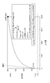
Logガンマを始め、撮像画像を非線形の入出力特性を有するガンマカーブを適用して変換する場合、コントローラ130がCγ処理部215およびYγ処理部222に対して使用するガンマ特性(入出力特性)を設定する。なお、上述の通り、Logガンマとは、例えば図7のように入力値の線形的な増加に対して出力値が対数的に増加する非線形な入出力特性を意味する。すなわち、
出力値=A×log10(B×入力値+C)+D
(0<A<1,B,C,Dは定数)といった対数式で表される入出力特性である。例えば、8ビットデータの場合、A=0.529136,B=10.1596,C=1.0,D=0.0730597とする。これにより、暗部は少しオフセットされた状態で黒つぶれを防ぎ、中間輝度部は階調を最低限のビット数で維持し、明部は飽和まで白とびを防いで階調を保つことが可能になる。
出力値=A×log10(B×入力値+C)+D
(0<A<1,B,C,Dは定数)といった対数式で表される入出力特性である。例えば、8ビットデータの場合、A=0.529136,B=10.1596,C=1.0,D=0.0730597とする。これにより、暗部は少しオフセットされた状態で黒つぶれを防ぎ、中間輝度部は階調を最低限のビット数で維持し、明部は飽和まで白とびを防いで階調を保つことが可能になる。
このLogガンマがユーザにより設定されている場合は、記録用動画専用撮影モードとなる。あるいは、ユーザが撮影モードとして記録用動画専用撮影モードを設定してる場合は、自動的に上述のLogガンマの変換が適用される。
なお、静止画のみの撮影の場合、図9に示されるように静止画を基準としたBT.601のガンマが適用される。また、動画記録中の静止画撮影が可能な通常撮影モードでの静止画撮影、特に動画記録中の静止画撮影に関しては、同じタイミングで撮影されている静止画像と動画像の画質を合わせるため、やはり静止画を基準としたBT.601のガンマが適用される。さらに別途、風景や夕景、人物ポートレート等のそれぞれの被写体のシーンに応じたガンマがマニュアルあるいはオートで設定され変換が行われる。なお、図9の通り、通常撮影モードにおける静止画、動画および記録用動画専用撮影モードにおけるプライマリ(色域)に関しては、BT.709に設定される。
ニー補正部217の出力信号(U,V)と輝度処理部から得られる信号(Y)は、第1ルックアップテーブル(以下、第1LUT)218に供給され、画像処理部106からの最終的なYUV信号が生成され、出力される。なお、画像処理部106のうち、色処理部および第1LUT218が信号処理部を構成する。
図1に戻って、記録部109は、例えば入力されたYUV信号のフレーム間の相関性を利用するなどしてノイズ除去を行う。その後、記録部109は、第4マトリクス1091により必要に応じて、ノイズ除去後の画像信号を第2の色空間の画像信号に変換して、動画記録用の画像信号を生成する。第4マトリクス1091で色空間の変換を行うかどうか、行う場合はどのような変換を行うのか、はコントローラ130が設定する。また、記録部109では、付加情報とともに、予め設定された記録ファイルフォーマット(例えばExif:Exchangeable image file format)に従った画像ファイルを生成する。そして、メモリカードやハードディスクなどの記録媒体に画像ファイルを記録する。
外部出力部110は、外部出力用の画像信号を生成する。ここでは、外部出力部110はHDMI(High-Definition Multimedia Interface:登録商標)を通じて外部出力するための信号を生成するものとするが、他の規格に準拠した信号を生成してもよい。外部出力部では、第5マトリクス1101により必要に応じて色空間変換処理を実行する。第4マトリクス1101で色空間の変換を行うかどうか、行う場合はどのような変換を行うのか、はコントローラ130が設定する。外部出力部110はまた、必要に応じて解像度の変換を行ってもよい。例えばHDMIから出力する場合は、HDMI規格で定められている解像度の何れか(例えば1920×1080や1280×720)に変換する。
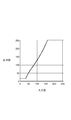
表示部111は、表示用の画像信号を生成し、デジタルカメラ100が有する表示装置(本例では、デジタルカメラ100の背面に設けられたLCDとする)に表示させる。表示部111は、画像の解像度を表示装置の解像度に対応するように変換し、必要に応じて階調補正を行うLUTを適用する。ここで、LUTの適用が必要なのは、Logガンマを適用して動画撮影している場合のモニタ時、あるいはLogガンマを適用して撮影された動画像の再生時である。上述の通り、Logガンマを適用して撮影された動画像はそのままの状態で表示しても、撮影結果を正しく評価することができない。そのため、視覚特性に対してリニアな階調になるようなガンマによる処理が行われた状態をシミュレーションするためのLUTを適用して表示するようにする。このようなLUTはviewing LUTと呼ばれ、具体的には、図8に示されるような、Logガンマで抑えていた中間輝度部のコントラストを上げる特性を有するLUTである。これにより、標準的な映像色空間(例えばBT.709)に従った明るさが再現される。つまり、例えば、ユーザは撮影時にviewing LUTで変換される前の状態で階調を確認し、viewing LUTで変換された状態で最終的な画像をイメージしながら撮影を行うことが可能になる。viewing LUTは、Logガンマ以外のガンマカーブが用いられている場合には適用されない。また、それぞれの環境に応じたガンマのLUTを適用してシミュレーションをしても良い。
また表示部111は、第6マトリクス1111により必要に応じて画像信号を第3の色空間の画像信号に変換する。第6マトリクス1111で色空間の変換を行うかどうか、行う場合はどのような変換を行うのか、はコントローラ130が設定する。表示部111は、必要に応じてLUTおよび色空間の変換が適用された表示用の画像信号を表示装置に供給して表示する。
このような構成のデジタルカメラ100における、色空間変換処理動作を説明する前に、従来のデジタルスチルカメラにおけるHD動画記録時の色空間変換処理について説明する。
図3は、デジタルカメラ100のうち、色空間変換処理に係る構成を抜き出して模式的に示した図である。参照数字は図1、図2A、図2Bと共通である。
図3は、デジタルカメラ100のうち、色空間変換処理に係る構成を抜き出して模式的に示した図である。参照数字は図1、図2A、図2Bと共通である。
画像処理部106には、撮像部101からRGB形式の画像信号が入力される。第1マトリクス212は、RGB形式の画像信号を、BT.601色空間のYUV形式の画像信号に変換する。BT.601色空間への変換は、デジタルカメラにおける静止画撮影時において広く一般的に行われているものである。
静止画画像は一般的にJPEGファイルで出力される。JPEGで規定されているRGB-YUVマトリクス係数は、BT601で定義されているマトリクス係数と同一である。また、前段でBT.601変換しておくことにより、後段ではマトリクス変換が不要になるため、JPEGファイルとして出力する静止画画質を優先することが出来る。そして、色処理を行った後、BT.601色空間のYUV形式で記録部109、外部出力部110、表示部111に供給される。
上述の通り、HD動画像についてはBT.709色空間の画像信号であることが要求されるため、記録部109の第4マトリクス1091はBT.601色空間のYUV形式の画像信号をBT.709色空間のYUV形式の画像信号に変換する。なお、YUV形式のままでBT.601色空間からBT.709色空間(あるいはその逆)に変換するための演算式は、上述のRGB形式から各色空間におけるYUV形式への変換式の相互関係に基づいて得ることができる。
同様に、外部出力部110においても、HDMI等のHD解像度での出力を行う場合には、第5マトリクス1101でBT.601色空間のYUV形式の画像信号をBT.709色空間のYUV形式の画像信号に変換する。
一方、本実施形態におけるデジタルカメラ100の表示装置は、BT.601色空間の画像信号を要求するものであるため、表示部111の第6マトリクス1111は色空間変換処理を行わず、供給されたBT.601色空間のYUV形式をそのまま後段に供給する。
このように、従来の構成においては、HD動画撮影時には、適用されるガンマの種類によらず、第1マトリクス212でBT.601色空間のYUV形式の画像信号とされたのち、第4マトリクス1091でBT.709色空間のYUV形式の画像信号に変換される。
次に、本実施形態のデジタルカメラ100における色空間変換処理動作について、図4を参照して説明する。図4は図3と同様、デジタルカメラ100のうち、色空間変換処理に係る構成を抜き出して模式的に示した図である。参照数字は図1~図3と共通である。
ここでは、Logガンマを適用した動画撮影時における色空間変換処理について説明する。Logガンマを適用した動画撮影時には、他の(入力値の線形的な増加に対して出力値が対数的に増加しない入出力特性の)ガンマを適用する場合と異なり、動画撮影中の静止画撮影や、動画フレームが静止画として利用されたりする可能性を考慮する必要がない。つまり、静止画に用いる色空間と合わせる必要がない。
そのため、コントローラ130は、Logガンマを適用した動画撮影時には、第1マトリクス212を、BT.601色空間のYUV形式ではなく、記録用信号に要求される色空間と等しいBT.709色空間のYUV形式の画像信号に変換するよう設定する。そして、色処理についても、必要に応じてBT.709色空間の画像信号用の処理を実行する。なお、色処理の内容を画像信号の色空間に応じて変更する必要がある場合、コントローラ130が必要なブロックに対して処理の切り替えを指示したり、パラメータなどの設定値を変更したりする。
従って、画像処理部106からは、BT.601色空間のYUV形式ではなくBT.709色空間のYUV形式の画像信号が出力される。これにより、記録部109および外部出力部110においては色空間の変換を行う必要がなくなる。そのため、コントローラ130は、第4および第5マトリクス1101および1111に、色空間の変換を行わないように設定する。従って、優先すべき動画記録用の画像信号に対して適用される色空間変換処理の回数を、図3の場合が2回であるのに対し、1回に減らすことができる。
一方、表示部111では、BT.601色空間のYUV形式の画像信号への変換が必要となる。そのため、コントローラ130は、第6マトリクス1111に、BT.709色空間のYUV形式の画像信号をBT.601色空間のYUV形式の画像信号に変換するよう設定する。
説明したコントローラ130の動作を、図5のフローチャートを用いて説明する。S101でコントローラ130は、Logガンマの使用が設定されたかどうか判定する。例えば、Logガンマ設定メニュー画面に含まれる、Logガンマの使用・不使用の設定項目311が操作部103を通じて選択、実行(決定)されると、コントローラ130はLogガンマの使用が設定されたと判定する。
Logガンマの使用が設定された場合、S103でコントローラ130は、Cγ処理部215およびYγ処理部222が用いるガンマ特性(入出力特性)にLogガンマを設定する。
また、コントローラ130は、Logガンマの使用が設定されると、画像処理部106の第1マトリクス212に、Logガンマで変換された動画信号の記録に要求される色空間に等しい色空間におけるYUV形式の画像信号に変換するよう設定する。本実施形態では、コントローラ130は、RGB形式の画像信号をBT.709色空間のYUV形式の画像信号に変換するよう、第1マトリクス212に設定する。
S105でコントローラ130は、色処理を行うブロック213~217に対し、色空間の変更に伴って処理内容を変更する必要があれば、変更を指示する(設定パラメータを変更する)。
なお、コントローラ130は、参照可能な例えば不揮発性メモリに、設定可能なガンマ特性に対応づけて、色空間変換処理や色処理に関する構成要素に対する設定値をあらかじめ記憶しておくことができる。そして、コントローラ130は、設定されているガンマ特性が変更されると、不揮発性メモリを参照して、変更後のガンマ特性に応じて、必要な機能ブロックに対する設定を変更することができる。
S107でコントローラ130は、記録部109(第4マトリクス1091)および外部出力部110(第5マトリクス1101)に対し、色空間の変換を行わないように設定する。一方で、表示部111(第6マトリクス1111)に対しては、表示用の信号に要求される色空間への変換を行うよう設定する。本実施形態では、コントローラ130は、BT.709色空間のYUV形式の画像信号を、BT.601色空間のYUV形式の画像信号に変換するよう、第6マトリクス1111に設定する。
(変形例)
なお、理解を容易にするため、Logガンマの使用が設定された際に記録用画像信号に必要な色空間の変換が、第1マトリクス212による変換のみで足りるものとしてこれまで説明してきた。しかし、マトリクス演算による理論的な色空間全体の均一な写像演算に加え、部分的な修正を行うことが望ましい場合もある。このような場合には、マトリクス演算と、ルックアップテーブルとの組み合わせを用いて色空間の変換を実現してもよい。ルックアップテーブルを用いることで、色空間内の特定の色域に対してのみ修正を行うことが可能である。
なお、理解を容易にするため、Logガンマの使用が設定された際に記録用画像信号に必要な色空間の変換が、第1マトリクス212による変換のみで足りるものとしてこれまで説明してきた。しかし、マトリクス演算による理論的な色空間全体の均一な写像演算に加え、部分的な修正を行うことが望ましい場合もある。このような場合には、マトリクス演算と、ルックアップテーブルとの組み合わせを用いて色空間の変換を実現してもよい。ルックアップテーブルを用いることで、色空間内の特定の色域に対してのみ修正を行うことが可能である。
この場合、ルックアップテーブルによる修正は、色処理や輝度処理が終了した後に行うことが望ましい。そのため、図6に示すように、画像処理部106からの最終的なYUV信号を生成する第1LUT218で行うことが望ましい。
このように、本実施形態によれば、Logガンマを適用した動画撮影が可能な撮像装置において、Logガンマを適用した動作撮影時には、記録用の信号に要求される色空間と等しい色空間の画像信号に変換してから色処理や輝度処理を行うようにした。そのため、撮像素子から出力されてから、記録されるまでに適用される色空間変換処理の回数を実質的に1回に減らすことが可能となり、従来のデジタルスチルカメラにおける動画撮影機能をそのまま利用する場合よりも、画質の劣化を低減できる。Logガンマは、8bitデータであったとしても、映画やテレビ用に最適化させるため、例えば意図的に16-254といった狭いダイナミックレンジで定義される。したがって、高画質を維持するためには、トーンジャンプが生じる恐れがある色変換の回数を減少させることはより効果的である。
また、画素の階調レンジについても今回の色空間と同様に考えることが出来る。すなわち、動画記録中に静止画撮影が可能な通常撮影モードでは、撮影タイミングにおける静止画像と動画像の画質を合わせる必要があるので、レンジも動画用と静止画用の異なる階調レンジには変換しないようにする。仮にそれぞれを専用の階調レンジに変換する場合は、後段の色変換で行うため、画質劣化が起こりやすい。
記録用動画専用撮影モードの場合は、図9に示されるようにLogガンマが適用され、静止画に合わせる必要がない。そのため、デジタルシネマや映画用のレンジ16-245で記録するため、画像処理部106では既に16-245のレンジで処理を行い、後段ではレンジの変換を行わないようにすることによってマトリクス変換と同様に画質劣化を回避することが出来る。
なお、本実施形態では、BT.709色空間とBT.601色空間との間の変換について説明したが、本発明はこれら特有の色空間の間の変換を対象としたものではない。例えば、映画芸術科学アカデミー(AMPAS)が提案しているACES(Academy Color Encode Specification)規格の色空間との間の変換にも適用できる。この場合、画像処理の内容が記載されたLMT(Look Modification Transform)ファイルが、画像データに関連付けられたり、画像データに記録されたりする。第1の実施形態では、映画芸術科学アカデミー(AMPAS)が提案している記述言語であるCTL(Color Transform Language)形式でLMTファイルを生成すればよい。CTLはインタプリタ型の言語であり、LMTファイルに記述された命令を解釈しながら、命令に従った画像処理を入力画像ファイルに適用することが可能である。LMTファイルが記録された画像データを受け取った画像処理装置は、設定されたLMTファイルに記述された画像処理が実行可能となる。
また、本実施形態において、記録用、外部出力用、および表示用の画像信号に要求される色空間についても単なる例示である。従って、記録用と外部出力用の画像信号に要求される色空間が常に等しいとは限らず、また本発明がそのような場合にのみ適用可能である訳でもない。また、記録、外部出力、表示という3系統も単なる例示であり、複数であれば数に制限はない。
本発明は、動画像信号を複数の出力先に供給する撮像装置において、色処理および輝度処理の前後における色空間変換処理の内容を、優先すべき出力先が要求する色空間に適合させるために必要な色変換処理の回数が最小になるように決定することを特徴とする。具体的には、撮像素子から出力されてから最終的な出力形態(記録、外部出力、表示など)に対応した画像信号とされるまでの間に適用される色空間変換処理の回数を、優先すべき出力形態に対する画像信号について最小化するものである。従って、記録よりも表示を優先すべき場合、表示用の画像信号が生成される過程で適用される色空間の変換処理の回数が最小となるように、色空間変換マトリクスの処理内容を設定する。また、必要な色空間の変換処理については、できるだけ処理の上流(撮像素子側)で行うようにすることで、画質劣化を一層抑制することができる。
本発明は、Logガンマを適用した動画撮影時において特に有効ではあるが、画質を最優先すべき信号系統における色空間変換処理の回数を最小化することによる画質劣化抑制効果は、Logガンマを適用した動画撮影時に限定されない。
また、本発明は、以下の処理を実行することによっても実現される。即ち、上述した実施形態の機能を実現するソフトウェア(プログラム)を、ネットワーク又は各種記憶媒体を介してシステム或いは装置に供給し、そのシステム或いは装置のコンピュータ(またはCPUやMPU等)がプログラムを読み出して実行する処理である。
本発明は上記実施の形態に制限されるものではなく、本発明の精神及び範囲から離脱することなく、様々な変更及び変形が可能である。従って、本発明の範囲を公にするために、以下の請求項を添付する。
本願は、2012年4月11日提出の日本国特許出願特願2012-90596を基礎として優先権を主張するものであり、その記載内容の全てを、ここに援用する。
Claims (6)
- 撮像素子から出力された画像信号を、第1の色空間の画像信号に変換する第1の変換手段と、
前記第1の色空間の画像信号に対して色処理を適用して出力する信号処理手段と、
前記信号処理手段が出力する画像信号から動画記録用の画像信号を生成する記録用信号生成手段であって、前記動画記録用の画像信号に要求される第2の色空間が前記第1の色空間と異なる場合には、前記信号処理手段が出力する画像信号を前記第2の色空間の信号に変換する第2の変換手段とを有する記録用信号生成手段と、
前記信号処理手段が出力する画像信号から、表示装置に対する表示用の画像信号を生成する表示用信号生成手段であって、前記表示用の画像信号に要求される第3の色空間が前記第1の色空間と異なる場合には、前記信号処理手段が出力する画像信号を前記第3の色空間の信号に変換する第3の変換手段とを有する表示用信号生成手段と、
前記第1から第3の変換手段の動作を制御する制御手段と、を有し、
前記制御手段は、動画記録と表示とのうち、優先すべき一方に用いる画像信号が生成される過程で適用される色空間の変換処理の回数が最小となるように、前記第1から第3の変換手段の動作を制御することを特徴とする撮像装置。 - 前記制御手段は、前記撮像装置が入力値の線形的な増加に対して出力値が対数的に増加する入出力特性で変換された動画像を記録する場合には、前記第1の色空間が前記第2の色空間と等しくなるように前記第1の変換手段を制御することを特徴とする請求項1に記載の撮像装置。
- 前記制御手段は、前記撮像装置が前記入出力特性で変換されない動画像を記録する場合には、前記第1の色空間が前記第3の色空間と等しくなるように前記第1の変換手段を制御することを特徴とする請求項2に記載の撮像装置。
- 前記制御手段は、前記撮像装置が静止画を記録する場合には、前記第1の色空間が前記第3の色空間と等しくなるように前記第1の変換手段を制御することを特徴とする請求項1ないし請求項3のいずれか1項に記載の撮像装置。
- 前記第1の色空間は、BT.601規格に準拠した色空間であり、前記第2の色空間はBT.709規格に準拠した色空間であることを特徴とする請求項1から請求項4の何れか1項に記載の撮像装置。
- 撮像素子から出力された画像信号を、第1の色空間の画像信号に変換する第1の変換手段と、
前記第1の色空間の画像信号に対して色処理を適用して出力する信号処理手段と、
前記信号処理手段が出力する画像信号から動画記録用の画像信号を生成する記録用信号生成手段であって、前記動画記録用の画像信号に要求される第2の色空間が前記第1の色空間と異なる場合には、前記信号処理手段が出力する画像信号を前記第2の色空間の信号に変換する第2の変換手段とを有する記録用信号生成手段と、
前記信号処理手段が出力する画像信号から、表示装置に対する表示用の画像信号を生成する表示用信号生成手段であって、前記表示用の画像信号に要求される第3の色空間が前記第1の色空間と異なる場合には、前記信号処理手段が出力する画像信号を前記第3の色空間の信号に変換する第3の変換手段とを有する表示用信号生成手段と、を有する撮像装置の制御方法であって、
動画記録と表示とのうち、優先すべき一方に用いる画像信号が生成される過程で適用される色空間の変換処理の回数が最小となるように、前記第1から第3の変換手段の動作を制御する制御工程を有することを特徴とする撮像装置の制御方法。
Priority Applications (1)
| Application Number | Priority Date | Filing Date | Title |
|---|---|---|---|
| US13/960,194 US8854256B2 (en) | 2012-04-11 | 2013-08-06 | Image capture apparatus and method of controlling the same |
Applications Claiming Priority (2)
| Application Number | Priority Date | Filing Date | Title |
|---|---|---|---|
| JP2012-090596 | 2012-04-11 | ||
| JP2012090596A JP5975705B2 (ja) | 2012-04-11 | 2012-04-11 | 撮像装置およびその制御方法、画像処理装置および画像処理のための方法 |
Related Child Applications (1)
| Application Number | Title | Priority Date | Filing Date |
|---|---|---|---|
| US13/960,194 Continuation US8854256B2 (en) | 2012-04-11 | 2013-08-06 | Image capture apparatus and method of controlling the same |
Publications (1)
| Publication Number | Publication Date |
|---|---|
| WO2013153809A1 true WO2013153809A1 (ja) | 2013-10-17 |
Family
ID=49327393
Family Applications (1)
| Application Number | Title | Priority Date | Filing Date |
|---|---|---|---|
| PCT/JP2013/002444 Ceased WO2013153809A1 (ja) | 2012-04-11 | 2013-04-10 | 撮像装置およびその制御方法 |
Country Status (3)
| Country | Link |
|---|---|
| US (1) | US8854256B2 (ja) |
| JP (1) | JP5975705B2 (ja) |
| WO (1) | WO2013153809A1 (ja) |
Families Citing this family (2)
| Publication number | Priority date | Publication date | Assignee | Title |
|---|---|---|---|---|
| US9924074B2 (en) * | 2016-05-23 | 2018-03-20 | Xerox Corporation | Method and system for enabling optimal colorant job programming |
| JP2024162981A (ja) * | 2023-12-08 | 2024-11-21 | パナソニックIpマネジメント株式会社 | 撮像装置 |
Citations (3)
| Publication number | Priority date | Publication date | Assignee | Title |
|---|---|---|---|---|
| JP2008072340A (ja) * | 2006-09-13 | 2008-03-27 | Canon Inc | 色処理装置 |
| JP2009147463A (ja) * | 2007-12-11 | 2009-07-02 | Canon Inc | 撮像装置及びその制御方法 |
| JP2011055089A (ja) * | 2009-08-31 | 2011-03-17 | Sanyo Electric Co Ltd | 色調整装置 |
Family Cites Families (4)
| Publication number | Priority date | Publication date | Assignee | Title |
|---|---|---|---|---|
| US20020196346A1 (en) * | 2001-03-15 | 2002-12-26 | Satoru Nishio | Image processing apparatus |
| JP4368127B2 (ja) * | 2003-04-04 | 2009-11-18 | ソニー株式会社 | 撮像装置におけるガンマ補正装置 |
| JP2008245248A (ja) * | 2007-02-28 | 2008-10-09 | Fujifilm Corp | 撮像装置 |
| JP2009225401A (ja) * | 2008-03-19 | 2009-10-01 | Casio Comput Co Ltd | 撮像装置、画像処理装置および画像処理方法 |
-
2012
- 2012-04-11 JP JP2012090596A patent/JP5975705B2/ja not_active Expired - Fee Related
-
2013
- 2013-04-10 WO PCT/JP2013/002444 patent/WO2013153809A1/ja not_active Ceased
- 2013-08-06 US US13/960,194 patent/US8854256B2/en not_active Expired - Fee Related
Patent Citations (3)
| Publication number | Priority date | Publication date | Assignee | Title |
|---|---|---|---|---|
| JP2008072340A (ja) * | 2006-09-13 | 2008-03-27 | Canon Inc | 色処理装置 |
| JP2009147463A (ja) * | 2007-12-11 | 2009-07-02 | Canon Inc | 撮像装置及びその制御方法 |
| JP2011055089A (ja) * | 2009-08-31 | 2011-03-17 | Sanyo Electric Co Ltd | 色調整装置 |
Also Published As
| Publication number | Publication date |
|---|---|
| US20130321658A1 (en) | 2013-12-05 |
| JP5975705B2 (ja) | 2016-08-23 |
| JP2013219695A (ja) | 2013-10-24 |
| US8854256B2 (en) | 2014-10-07 |
Similar Documents
| Publication | Publication Date | Title |
|---|---|---|
| US10412296B2 (en) | Camera using preview image to select exposure | |
| JP5873380B2 (ja) | 画像処理装置およびその制御方法 | |
| JP7157714B2 (ja) | 画像処理装置およびその制御方法 | |
| US11798143B2 (en) | Image processing apparatus and control method thereof | |
| JP2014167609A (ja) | 画像処理装置及びその制御方法、プログラム、記憶媒体 | |
| JP2017212532A (ja) | 画像処理装置 | |
| JP5223686B2 (ja) | 撮像装置および撮像方法 | |
| JP6092690B2 (ja) | 撮像装置およびその制御方法 | |
| JP5803233B2 (ja) | 撮像装置および撮像方法 | |
| JP5975705B2 (ja) | 撮像装置およびその制御方法、画像処理装置および画像処理のための方法 | |
| CN120034743A (zh) | 图像处理设备、摄像设备、图像处理方法、存储介质和计算机程序产品 | |
| JP5914124B2 (ja) | 撮像装置およびその制御方法 | |
| JP5904753B2 (ja) | 画像処理装置及び画像処理装置の制御方法 | |
| JP6247513B2 (ja) | 撮像装置、制御方法およびプログラム | |
| JP6072191B2 (ja) | 画像処理装置及び画像処理装置の制御方法 | |
| JP4978669B2 (ja) | 画像処理装置、電子カメラ、および画像処理プログラム | |
| JP2015122585A (ja) | 画像処理装置、撮像装置、画像処理方法、及びプログラム | |
| JP2012105354A (ja) | 画像処理装置、電子カメラ、および画像処理プログラム |
Legal Events
| Date | Code | Title | Description |
|---|---|---|---|
| 121 | Ep: the epo has been informed by wipo that ep was designated in this application |
Ref document number: 13776260 Country of ref document: EP Kind code of ref document: A1 |
|
| NENP | Non-entry into the national phase |
Ref country code: DE |
|
| 122 | Ep: pct application non-entry in european phase |
Ref document number: 13776260 Country of ref document: EP Kind code of ref document: A1 |