WO2013146405A1 - 画像符号化装置及び画像復号装置 - Google Patents
画像符号化装置及び画像復号装置 Download PDFInfo
- Publication number
- WO2013146405A1 WO2013146405A1 PCT/JP2013/057620 JP2013057620W WO2013146405A1 WO 2013146405 A1 WO2013146405 A1 WO 2013146405A1 JP 2013057620 W JP2013057620 W JP 2013057620W WO 2013146405 A1 WO2013146405 A1 WO 2013146405A1
- Authority
- WO
- WIPO (PCT)
- Prior art keywords
- mapping
- prediction
- pixel signal
- encoded
- signal
- Prior art date
- Legal status (The legal status is an assumption and is not a legal conclusion. Google has not performed a legal analysis and makes no representation as to the accuracy of the status listed.)
- Ceased
Links
Images


Classifications
-
- H—ELECTRICITY
- H04—ELECTRIC COMMUNICATION TECHNIQUE
- H04N—PICTORIAL COMMUNICATION, e.g. TELEVISION
- H04N19/00—Methods or arrangements for coding, decoding, compressing or decompressing digital video signals
- H04N19/50—Methods or arrangements for coding, decoding, compressing or decompressing digital video signals using predictive coding
- H04N19/503—Methods or arrangements for coding, decoding, compressing or decompressing digital video signals using predictive coding involving temporal prediction
- H04N19/51—Motion estimation or motion compensation
-
- H—ELECTRICITY
- H04—ELECTRIC COMMUNICATION TECHNIQUE
- H04N—PICTORIAL COMMUNICATION, e.g. TELEVISION
- H04N19/00—Methods or arrangements for coding, decoding, compressing or decompressing digital video signals
- H04N19/50—Methods or arrangements for coding, decoding, compressing or decompressing digital video signals using predictive coding
-
- H—ELECTRICITY
- H04—ELECTRIC COMMUNICATION TECHNIQUE
- H04N—PICTORIAL COMMUNICATION, e.g. TELEVISION
- H04N19/00—Methods or arrangements for coding, decoding, compressing or decompressing digital video signals
- H04N19/60—Methods or arrangements for coding, decoding, compressing or decompressing digital video signals using transform coding
- H04N19/61—Methods or arrangements for coding, decoding, compressing or decompressing digital video signals using transform coding in combination with predictive coding
Definitions
- the present invention relates to an image encoding device and an image decoding device, and more particularly to image encoding for calculating a mapping coefficient for reducing a correlation between signals from encoded pixels and applying the calculated coefficient to a pixel to be encoded.
- the present invention relates to a device and an image decoding device.
- Non-Patent Document 1 There are a frame difference method and a motion compensation method as a method for reducing the time redundancy.
- the frame difference method simply subtracts two consecutive images and encodes the difference.
- an approximate image of an encoding target frame is generated by applying a motion vector to a reference frame, and a difference from the encoding target frame is encoded. Since encoding is performed while reducing the difference between images, the motion compensation method is superior in encoding efficiency to the frame difference method.
- Various methods for estimating the motion vector used in the motion compensation method have been proposed, and the main prior art relating to motion estimation is introduced in Non-Patent Document 1.
- Non-Patent Document 2 introduces main prior art related to orthogonal transform.
- an encoded signal is generated by performing an encoding process on a decorrelated signal.
- no coding is determined by selecting the closest one from the finite number of decorrelation transformation matrices to the decorrelation transformation matrix obtained by the principal component analysis method on the encoding side.
- a method is also described in which a decorrelation transformation matrix is specified in accordance with auxiliary information indicating a unique number of the correlation transformation matrix, and decorrelation inverse transformation is executed.
- Motion compensation reduces time redundancy but cannot be used for still images.
- the combination of orthogonal transform and quantization and the spatial prediction method reduce the spatial redundancy, but none of them can reduce the redundancy of the color signal because the color signal is processed independently.
- Patent Document 1 that reduces signal redundancy holds the information of the decorrelation matrix used for decorrelation conversion as a decorrelation parameter, it is difficult to significantly improve the coding efficiency. In the embodiment using the approximate matrix, even if the amount of information to be transmitted can be significantly reduced, redundancy reduction by decorrelation is not sufficient.
- the present invention encodes a pixel signal of an encoding target pixel configured in a predetermined color space for each unit block in the form of a mapped pixel signal mapped to a space that reduces correlation between signals.
- An image encoding device for converting to a pixel signal to be encoded by calculating a mapping coefficient for reducing a correlation between the signals from the encoded pixel signal and applying the mapping coefficient.
- a prediction means for determining prediction information for predicting the mapping pixel signal to be encoded from the mapping pixel signal of the encoded pixel signal; and a prediction signal of the mapping pixel signal to be encoded based on the prediction information.
- mapping means for applying the mapping coefficient as an inverse mapping to the encoded mapped pixel signal to obtain an encoded pixel signal
- the mapping means being referred to by the prediction information
- the mapping coefficient is calculated from the encoded pixel signal in the predetermined area including the area and the mapping coefficient is applied to the encoding target pixel signal
- the encoded pixel of the predetermined area to be referred to is also referred to Applied to the signal
- said Measuring means than encoded mapping pixel signals of the applied predetermined area by mapping coefficients were characterized by predicting a mapping pixel signals of the encoding target.
- the present invention is an image decoding apparatus that decodes information encoded by the image encoding apparatus for each unit block into a pixel signal composed of the predetermined color space, Decoding means for decoding the encoded quantized value and prediction information; decoding side dequantizing means for inversely quantizing the quantized value to form a transform coefficient; Decoding side inverse transforming means to be a difference signal, Mapping pixel signal obtained from decoded pixel signal, and decoding information compensation means for generating a prediction signal of the mapping pixel signal for the pixel signal to be decoded from the prediction information A decoding side addition means for adding the prediction signal and the prediction residual signal to obtain a decoded mapped pixel signal; and the mapping coefficient from a decoded pixel signal in a predetermined region including a region referred to by the prediction information Decoding side mapping means for calculating, and decoding side inverse mapping means for applying the calculated mapping coefficient to the decoded mapped pixel signal as a reverse mapping to obtain a decoded
- the mapping coefficient when mapping the encoding target and decoding target pixel signals configured in a predetermined color space to the mapping pixel signal that reduces the redundancy between the signals is encoded.
- the mapping coefficient is calculated from a predetermined area including the reference area of the prediction information that can be regarded as a similar pixel of the block to be encoded / decoded.
- the encoding efficiency is improved.
- by applying the mapping to the pixel signal of the target block and the pixel area referred to by the prediction information it is possible to further apply the prediction to the mapped pixel signal, thereby improving the coding efficiency.
- FIG. 1 It is a functional block diagram of the encoding apparatus which concerns on one Embodiment. It is a functional block diagram of the decoding apparatus which concerns on one Embodiment. It is a figure for demonstrating the specific example of application of a mapping means etc. FIG.
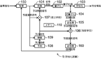
- FIG. 1 is a functional block diagram of an (image) encoding device according to an embodiment of the present invention.
- the encoding device 1 includes a transforming unit 101, a quantizing unit 102, an encoding unit 103, an (encoding side) inverse quantization unit 104, an (encoding side) inverse transform unit 105, an (encoding side) addition unit 106, Difference unit 107, prediction means 108, (encoding side) compensation means 109, (encoding side) memory 110, (encoding side) mapping means 150 and (encoding side) inverse mapping means 160, and a unit of encoding
- the pixel signal is encoded for each block.
- FIG. 2 is a functional block diagram of an (image) decoding apparatus according to an embodiment of the present invention corresponding to the encoding apparatus of FIG.
- Decoding device 2 includes decoding means 203, (decoding side) inverse quantization means 204, (decoding side) inverse transformation means 205, (decoding side) addition means 206, (decoding side) compensation means 209, and (decoding side) memory 210.
- decoding side mapping means 250 and (decoding side) inverse mapping means 260 are provided to decode the pixel signal for each unit block.
- the unit block size for encoding and decoding can be arbitrarily set. After determining the unit block, encoding and decoding may be performed for each predetermined small area obtained by subdividing the unit block.
- each functional block of FIG. 1 and FIG. 2 will be described.
- one of them is appropriately selected as “mapping means 150 (mapping means 250)” for simplification of explanation. It may be described in parentheses.
- FIG. 1 and FIG. 2 a common name is given to the functional blocks having the same or corresponding processes, and the same reference numerals are given in the last two digits.
- the memory 110 (and the memory 210) are encoded pixel signals (decoded pixel signals) required by the functional blocks of the encoding device 1 (and the decoding device 2), respectively.
- the encoded mapped pixel signal (decoded mapped pixel signal) is held for a necessary period, and each functional block provides the signal as necessary for processing, and represents the flow of data exchange at that time
- the arrows are not shown for simplification of the drawing. The data retention and exchange will be described as appropriate.
- the mapping means 150 which is a characteristic configuration of the present invention, (1) for each unit block for encoding the input pixel signal to be encoded, the input signal in the original predetermined color space, The signal is mapped to a signal (referred to as a mapped pixel signal) in a specific space in which the redundancy is reduced by reducing the correlation, and is passed to the conversion unit 101, the compensation unit 109, and the prediction unit 108.
- the mapping means 150 also obtains (2) a mapping coefficient representing the mapping in order to perform the mapping of (1).
- the mapping coefficient obtained in (2) can be obtained by using the encoded pixel signal stored in the memory 110 without using the unit block itself to be converted (1) that is actually converted. Therefore, it is not necessary to encode the mapping coefficient information.
- the initially input pixel signal is an RGB signal
- this is converted into a mapped pixel signal in the specific space ⁇ obtained in (2).
- the ⁇ space is generally required to be different for each unit block to be encoded that is converted in (1).
- the mapping unit 250 obtains a similar mapping coefficient by performing the same processing as the above (2) of the mapping unit 150 on the decoded pixel signal sent from the inverse mapping unit 260 and held in the memory 210. .
- the mapping unit 250 also applies the mapping coefficient to the decoded pixel signal in the region specified by the prediction information sent from the decoding unit 230 among the decoded pixel signals held in the memory 210, and the mapped pixel signal Ask for.
- the determined mapped pixel signal is used by the compensation unit 209 to generate a prediction signal from the prediction information.
- the inverse mapping unit 160 obtains a pixel signal by performing the reverse process of the mapping unit 150 (mapping unit 250) on the mapped pixel signal sent from the addition unit 106 (addition unit 206), By recording in the memory 110 (memory 210), the mapping means 150 (mapping means 250) can be referred to as necessary in the subsequent processing.
- mapping coefficient obtained by the mapping means 150 (mapping means 250) based on a predetermined pixel signal can be immediately used in the reverse mapping means 160 (reverse mapping means 260) by the flow of data exchange (not shown). It becomes a state where reverse mapping can be performed using the mapping coefficient. Details of mapping means 150 (mapping means 250) and reverse mapping means 160 (reverse mapping means 260) will be described later.
- the converting means 101 converts the prediction residual signal in the mapped pixel signal sent from the difference means 107 described later or the mapped pixel signal sent from the mapping means 150 into a frequency domain transform coefficient by orthogonal transformation.
- the transform coefficient obtained by the orthogonal transform is sent to the quantization means 102.
- DCT discrete cosine transform
- DWT discrete wavelet transform
- the conversion unit 101 performs the conversion on the mapped pixel signal sent from the mapping unit 150 instead of the prediction residual signal when using the intra prediction and is the first block in the frame, so that the prediction cannot be applied. This is the case.
- the quantization means 102 quantizes the transform coefficient sent from the transform means 101.
- the quantized value obtained by the quantization is sent to the inverse quantization means 104 and the encoding means 103.
- the quantization parameter used for the quantization process can be set as a combination of constant values. Alternatively, it is possible to improve the encoding efficiency by controlling according to the information amount of the transform coefficient.
- the quantization parameter is non-uniform depending on the element (eigenvalue) of the diagonal matrix representing the information amount of the spatial axis with respect to the transformation coefficient in each spatial axis mapped. It is also possible to set a quantization parameter (set a larger quantization parameter for an axis with a larger amount of information) and perform encoding.
- the encoding unit 103 encodes the quantized value (and the quantization parameter) sent from the quantizing unit 102 and outputs it as code information.
- code information For the encoding, a variable length code or an arithmetic code that removes redundancy between codes can be used.
- the decoding unit 203 decodes the input code information (output from the encoding unit 103 of the encoding device 1) by following the reverse procedure of the encoding process.
- the decoded quantization value (and quantization parameter) and prediction information are sent to the inverse quantization means 204 and the compensation means 209, respectively.
- the inverse quantization means 104 (inverse quantization means 204) performs inverse quantization on the quantized value sent from the quantization means 102 (decoding means 203) by following the reverse procedure of the quantization process.
- the transform coefficient including the quantization error obtained by the inverse quantization is sent to the inverse transform unit 105 (inverse transform unit 205).
- the inverse transform unit 105 (inverse transform unit 205) performs inverse orthogonal transform on the transform coefficient including the quantization error sent from the inverse quantization unit 104 (inverse quantization unit 204) by following the reverse procedure of the orthogonal transform. To do.
- the prediction residual signal or the mapped pixel signal including the quantization error obtained by the inverse transformation is sent to the adding means 106 (adding means 206) described later.
- the adding means 106 calculates the sum of the prediction residual signal sent from the inverse converting means 105 (inverse converting means 205) and the predicted signal sent from the compensating means 109 (compensating means 209) described later. . Note that when the mapped pixel signal is sent as it is instead of the prediction residual signal (in the case of the first block in the frame when using the intra prediction), the addition process is omitted.
- the mapping pixel signal obtained by the addition is sent to the inverse mapping means 160 (inverse mapping means 260) described later.
- the difference means 107 calculates the difference between the mapped pixel signal whose signal redundancy has been reduced by the mapping means 150 described later in detail and the prediction signal sent from the compensation means 109 described later in the unit block to be encoded.
- the prediction residual signal for the mapped pixel signal obtained by the subtraction is sent to the conversion means 101.
- the predicting means 108 is obtained by mapping a predetermined area (area corresponding to the reference source in the prediction information) of the encoded pixel signals held in the memory 110 into a mapped pixel signal by the mapping means 150. Prediction information for approximating the mapping target pixel signal obtained by mapping the encoding target input pixel signal (the encoding target block pixel signal) by the mapping means 150 is determined. The determined prediction information is sent to the compensation means 109 and the encoding means 103. Note that the data flow of the part where the prediction information is sent to the encoding means 103 is not shown.
- intra prediction intra-screen prediction
- intra prediction mode that individually encodes in each intra prediction mode and minimizes the cost calculated from the code amount and the distortion amount
- Predictive information Predictive information.
- motion prediction a frame and coordinates to be referenced are searched and used as prediction information. The application of the intra-screen prediction and motion prediction to the mapping pixel will be described together with the details of the mapping means 150 and the like.
- the compensation unit 109 maps the prediction information sent from the prediction unit 108 (decoding unit 203) and the encoded pixel signal of the reference source area in the prediction information by the mapping unit 150 (mapping unit 250).
- a prediction signal for the region to be encoded (the region to be decoded) is generated based on what has been mapped to the pixel signal.
- the prediction signal is sent to the difference means 107 and the addition means 106 in the encoding device 1 and to the addition means 206 in the decoding device 2.
- mapping coefficient in the mapping means 150 (the mapping means 250) will be described.
- similar pixels to the pixels in the encoding target block (decoding target block) are selected from the encoded region (decoded region) and used, so that both the encoding device 1 and the decoding device 2 have the same mapping. Since the coefficient can be calculated, it is not necessary to encode special additional information and transmit it from the encoding device 1 to the decoding device 2.
- a similar pixel is selected and used when obtaining the mapping coefficient, redundancy is reduced even when the mapping coefficient is applied to the pixel signal in the encoding target block (decoding target block). Therefore, the code amount can be reduced.
- pixels of adjacent blocks that have been encoded (decoded) with respect to the encoding target block (decoding target block) can be used. This is based on the fact that the target block and its neighboring blocks often have similar color characteristics. Further, the adjacent block to the processing target block may be changed according to each piece of prediction information used by the prediction means 108.
- the prediction information is expressed as a prediction mode.
- a predetermined region related to the region indicated by the prediction mode as a reference source of prediction can be used.
- the prediction mode is any one of DC, PLANE, 4, 5, and 6 in the intra prediction
- the left and upper block pixels are used as similar pixels, and the Intra prediction mode is 1 or If it is 8, the pixel of the left block is used, and if the Intra prediction mode is 0, 3, or 7, the pixel of the upper block is used.
- the prediction means 108 uses motion prediction, an area related to the area indicated by the prediction information can be used.
- the use of the intra prediction and the motion prediction for each frame may be determined in advance according to a known method.
- the unit used for calculating the mapping coefficient may be an encoding (decoding) processing unit block or a part of the processing unit block.
- encoding decoding
- adjacent pixels of the encoding target block (decoding target block) or the same region as the adjacent block can be extracted by area division using various known methods such as watershed, and the corresponding pixels can be used.
- the influence of noise is likely to be relatively large, so the region is expanded around the region until the predetermined number of pixels is reached. Also good. Conversely, when the number of pixels included in the region is large, there is an increased possibility that pixels having different correlations between channels will be included. It may be configured.
- the mapping coefficient is actually calculated or encoded with each candidate.
- the encoding may be actually performed with a size that minimizes the encoding cost (encoding including the size information).
- a predetermined size may be determined in advance by experiments or the like so that the size information need not be encoded.
- the size candidate or one predetermined size may be determined by intra prediction and inter prediction.
- mapping coefficient may be set for each region. For example, when similar pixels are configured with flat values, (1) apply a preset mapping coefficient, or (2) mapping coefficients already calculated in the adjacent block of the processing target block for the similar pixel By applying, the calculation load can be reduced, and the encoding efficiency can be improved by reducing the difference from the transform coefficient of the adjacent block.
- the process of performing mapping may be omitted, and the conversion means 101 and later may be processed as pixel signals instead of mapped pixel signals.
- a mapping coefficient corresponding to the identity mapping may be set in advance as the mapping coefficient to be applied.
- the adjacent block is also determined to be flat as a premise, and when the target blocks for which the adjacent pixel is determined to be flat are consecutive, it is assumed that the block is flat first.
- the mapping coefficient calculated from the adjacent pixel of the determined target block is subsequently used as the mapping coefficient in the target block determined to be flat. Further, whether or not it is flat may be determined by, for example, the concentration of pixels of a predetermined ratio or more in a predetermined range in the histogram of similar pixels.
- the calculated mapping coefficient is an input pixel signal to be encoded and a pixel signal that has been encoded and is held in the memory 110 and located at a location referenced by the prediction unit 108 and the compensation unit 109.
- the mapping pixel signal is obtained in the applied range, and the mapping pixel signal in the encoding target block is sent to the difference means 107, the compensation means 109, and the prediction means 108.
- the calculation of the mapping coefficient and the calculation of the mapped pixel signal based on the coefficient are performed for each prediction information candidate to be applied by the prediction unit 108 (in the decoding device 1 side, the predetermined prediction information is determined).
- the one corresponding to the prediction information that minimizes the cost calculated from the code amount and distortion amount when encoding by the encoding means 103 is actually the encoding device. 1 is output to the memory 110 so that the mapping means 150 can be referred to in the subsequent processing of the encoding target block. Saved.
- the calculated mapping coefficient is first applied by the mapping means 250 to the already decoded pixel signal in the region from which the compensation means 209 determined by the prediction information generates the prediction signal, A mapped pixel signal of the generation source area is obtained.
- the compensation unit 209 obtains a prediction signal by applying the prediction information to the mapped pixel signal of the region, and the prediction signal is added to the prediction residual signal by the addition unit 206, thereby obtaining a mapped pixel signal of the decoding target block. It is done.
- the calculated mapping coefficient is further applied as an inverse mapping by the inverse mapping means 260 to the mapping pixel signal of the decoding target block, whereby the pixel signal of the decoding target block is obtained and the decoding device 2 In addition to being output, it is stored in the memory 210 for reference by the mapping means 250 during subsequent processing of the decoding target block.
- mapping pixel signal in the target block to which mapping is applied is compensated from the mapping unit 150 to the difference unit 107, the compensation unit 109, and the prediction unit 108 in the encoding device 1, and from the mapping unit 250 in the decoding device 2.
- Sent to means 209. Separately from the flow of the data to be sent, the mapping pixel signal in the prediction source area required when applying the prediction information to the target block is calculated individually by the mapping unit 150 (mapping unit 250). To the prediction means 108 and the compensation means 109 (compensation means 209).
- the pixel signal to which the inverse mapping is applied is stored in the memory 110 from the inverse mapping unit 160 and then decoded by the mapping unit 150 in the encoding device 1 so as to be used in the subsequent processing of the target block.
- the image data is stored in the memory 210 from the inverse mapping means 260 and then sent to the mapping means 250 and output as a pixel signal.
- FIG. 3 is a diagram for explaining a specific example of application of the mapping means 150 and the like.
- the encoding target block (decoding target block) is set to B0 as shown in (1), and the pixel signal can be referred to when the block is to be encoded (decoded).
- the block (decoded) is the block A1 at the upper left of B0, the block A2 at the upper right of B0, the block A3 at the upper right of B0, and the block A4 at the left of B0.
- the arrangement of the blocks A1 to A4 with respect to the block B0 is performed in the order of raster scanning within the image, but may be in other orders. Further, some of the blocks A1 to A4 may not be referable.
- the case where the prediction unit 108 applies the prediction mode 0 (vertical prediction) of the intra prediction is (2), and the pixel B2 in the bottom row of the processed blocks A2 is adjacent to the processing target block B0. As a reference pixel, it is used to predict B0.
- the mapping means 150 obtains a mapping coefficient from all the pixels of the block A2. Using the mapping coefficient, the mapping unit 150 converts the pixel signal of the prediction source area (area referred to for prediction) B2 and the encoding target block B0 into a mapped pixel signal on the encoding device 1 side. Also, using the mapping coefficient, the mapping unit 250 converts the pixel signal of the prediction source region B2 into a mapped pixel signal on the decoding device 2 side.
- the compensation means 109 (compensation means 209) generates a prediction signal for the mapping pixel signal of the target block B0 from the mapping pixel signal of the prediction source region B2 according to the prediction information of the intra prediction mode 0.
- the mapping pixel signals of the prediction source region B2 and the prediction target region B0 are mapping pixel signals mapped to the same space with the common mapping coefficient obtained by the block A2. Therefore, even if prediction that was originally assumed to be used in a fixed color space such as RGB is used in a space defined by a different mapping relationship for each block in the present invention, the encoding efficiency can be improved. Therefore, it will function effectively.
- the encoding device 1 calculates a prediction residual signal for the mapping pixel signal of the target block B0 as a difference between the mapping pixel signal of the target block B0 and the prediction signal in the difference unit 107, and after the conversion unit 101 Passed to.
- the encoded pixel signal is encoded by the encoding unit 103 and reconstructed by the addition unit 106 on the other side, and the mapping unit 150 uses the mapping coefficient already obtained from the block A2 by the inverse mapping unit 160.
- the inverse mapping is performed to obtain a reconstructed pixel signal of the block B0, and the subsequent processing target block is stored in the memory 110 for reference by the mapping means 150.
- the decoding device 2 obtains the mapping pixel signal of the target block B0 as the sum of the prediction residual signal of the mapping pixel signal of the target block B0 and the prediction signal in the adding unit 206, By using the mapping coefficient calculated in the block A2 already obtained by the mapping means 250, the inverse mapping means 260 performs inverse mapping to obtain the reconstructed pixel signal of the target block B0, and the decoding device 2 And the subsequent processing target block is held in the memory 210 to be referred to by the mapping means 250.
- the mapping coefficient is obtained from the encoded adjacent block A2 of the target block B0 including the reference pixel region B2 used for prediction. Since the adjacent block A2 is in contact with the target block B0, it is generally highly likely that the color distribution is similar. Therefore, the mapping coefficient obtained from A2 is highly likely to reduce the redundancy of B0.
- the mapping coefficient may be obtained not only from all the pixels of the block A2, but only from a part thereof, but the part preferably includes B2. Also, within the encoded (decoded) area that can be referred to at the time of the determination, the mapping means 150 (mapping means 250) applies area division as an additional process, etc. The mapping coefficient may be calculated using a region (a region obtained by adding the block A2 or the region B2 itself) to which the features are determined to be the same.
- (3) is an example of the case where prediction mode 1 (horizontal prediction) of intra-screen prediction is applied by the prediction means 108, and instead of the bottom row B2 of A2 in the case of (2), the lowest of A4
- the right row B3, that is, the reference pixel area corresponding to the prediction mode 1 is replaced with the block A4 (next to the left of B0) instead of the block A2 (the left adjacent to B0), that is, the adjacent block including the reference pixel.
- encoding and decoding can be performed by applying prediction in the case of (3) just like the case of (2).
- (4) is an example of applying prediction mode 2 (DC prediction) for intra prediction in the prediction means 108, and instead of the bottom row A2 of A2 in the case of (2), the bottom row of A2
- the reference pixel area corresponding to the prediction mode 2 corresponding to the prediction mode 2 is replaced with the blocks A1, A2 and A4 (B0) instead of the block A2 (above B0).
- the encoding and decoding are applied in the case of (4) in the same way as in (2). Is possible.
- the present invention can be applied in the same manner when using other prediction modes for in-screen prediction. That is, in the case of prediction mode 4, 5 or 6, the same reference pixel and adjacent block as in (4) are used, and in the case of prediction mode 8, the same reference pixel and adjacent block as in (3) are used. In the case of prediction mode 3 or 7, the same reference pixel and adjacent block as in (2) may be used.
- the prediction means 108 uses motion prediction (inter-screen prediction), similarly, as shown in (5), the area indicated by the prediction information by motion prediction is used as a reference pixel (instead of an adjacent block) as a reference block. do it.
- the target block B0 in the frame F0 is predicted by the block B1 in another frame F1
- the information of the reference frame and the reference block is encoded as prediction information
- the block B1 is A2 (mapping coefficient) in the case of (2).
- Prediction and encoding / decoding can be applied by treating as B2 (calculation target as a prediction source region) and B2 (target for calculating a mapping pixel).
- the block B1 in (5) is not the referenced block itself, but is set as a larger predetermined block that includes the referenced block inside, thereby improving the resistance to noise. You may make it have.
- the prediction means 108 when applying a predetermined intra-screen prediction such as intra-screen prediction, for example, the prediction means 108 actually encodes each of the prediction modes as described above. And the one that minimizes the cost calculated from the code amount and the distortion amount is selected. Even when motion prediction is used, it is assumed that all are individually encoded within a predetermined range and the cost is similarly minimized.
- the size of the encoding unit block does not necessarily have to be 4 ⁇ 4. You may make it utilize.
- the block is directly converted as a pixel signal without performing mapping / inverse mapping or prediction.
- the mapping means 150 and the like obtain mapping coefficients that reduce the correlation between signals in a predetermined color space by principal component transformation and apply them as mapping / inverse mapping.
- the specific procedure of application is as follows. First, to calculate the mapping coefficient, the input pixel signal is separated into m signals.
- the type and number of signals to be separated are not limited, but as an example, it is possible to use a color space signal such as an RGB color signal, a YUV color signal, or a Y color CbCr color signal. If the input pixel signal is previously configured in a predetermined color space, the color space may be used as it is.
- the matrix P calculates the product of the transposed matrix P t as the matrix A (Formula 3).
- t represents a transposition operation.
- the matrix A is a symmetric matrix with the number of elements m of the signal in which both the number of rows and columns are separated. Therefore, the matrix A can be decomposed into matrix products as in the following equation (equation 4).
- U and V are mxm orthogonal matrices
- ⁇ is an mxm diagonal matrix in which the singular values ⁇ i (1 ⁇ i ⁇ rankA) of the matrix A are arranged in descending order.
- Singular value sigma i is the square of the eigenvalue lambda i of A t A.
- the column vector v i of V as shown in the following equation (Equation 6) is obtained as the eigenvector corresponding to the eigenvalue sigma i 2 of A t A.
- the quantization parameter in the above-described quantization means 102 may be determined according to the eigenvalue ⁇ i 2 corresponding to the information amount on the space axis.
- Equation 7 the orthogonal matrix V t is applied to the encoding target pixel Q as a mapping coefficient to calculate a mapped pixel signal Q ′ (Equation 7).
- mapping coefficient used in the inverse mapping means 160 and 260 is given by the orthogonal matrix U, and the pixel signal Q is calculated from the mapped pixel signal Q ′ by the following equation (Equation 8). At this time, the final pixel signal is obtained by making the average not equal to zero by the reverse operation of (Equation 2). That is, the mapping coefficient includes information for shifting the average of (Equation 2).
- the matrix P is obtained from the pixel signal of the block A2, and the mapped pixel signal Q ′ can be obtained by applying it to the block B0 where the encoding target pixel Q exists. Become.
Landscapes
- Engineering & Computer Science (AREA)
- Multimedia (AREA)
- Signal Processing (AREA)
- Compression Or Coding Systems Of Tv Signals (AREA)
Abstract
符号化効率の高い画像符号化装置及び画像復号装置を提供する。 写像手段150にて、所定の色空間で構成された符号化対象の画素信号を主成分分析により信号間の冗長性を低減させる写像画素信号へと写像する。その写像係数は、符号化済みの画素信号から算出することで、写像係数の符号化を不要とすると共に、符号化・復号対象ブロックの類似画素からなる隣接ブロックの画素信号から算出することで、冗長性を大きく低減させる。写像は、対象ブロックの画素信号及び予測情報が参照する画素の領域に適用することで、写像画素信号にさらに予測の適用を可能とし、変換・量子化の後符号化すると共に逆変換・逆量子化する。逆写像手段160にて逆写像を適用することで、写像画素信号から画素信号へと戻す。
Description
本発明は,画像符号化装置および画像復号装置に関し,特に,符号化済みの画素から信号間相関を低減させる写像係数を算出して、符号化対象画素に適用した上で符号化する画像符号化装置及び画像復号装置に関するものである.
従来の画像符号化において符号化効率を向上させる方式としては、時間冗長性を削減す る方法と空間冗長性を削減する方法と信号冗長性を削減する方法とがある。
時間冗長性を削減する方法としては、フレーム差分方式や動き補償方式がある。フレーム差分方式は連続する2枚の画像を単純に減算し差分を符号化する。動き補償方式は、参照フレームに対して動きベクトルを適用することで符号対象フレームの近似画像を生成し、符号対象フレームとの差分を符号化する。画像間の相違を小さくした上で符号化するため、動き補償方式はフレーム差分方式より符号化効率の面で優れる。動き補償方式で用いる動きベクトルの推定方法は様々な方式が提案されており、動き推定に関する主要な従来技術は非特許文献1にて紹介されている。
一方、空間冗長性を削減する方法としては、直交変換係数を量子化する方式がある。直交変換は画素信号を周波数領域に写像し、エネルギーを低域に集中させる。人間の視覚特性が高域に敏感でないことを利用して、高域成分を量子化で除去することで符号化効率を上げることが可能となる。また、直交変換係数乃至画素の予測による空間冗長性削減手法がある。直交変換に関する主要な従来技術は非特許文献2にて紹介されている。
信号冗長性を削減する方法としては、主成分分析で信号間の相関を削減する方法がある。特許文献1では、無相関化した信号に対して符号化処理を施して符号化信号を生成する。同文献の別の実施例では、符号化側で主成分分析法で求めた無相関化変換行列に対して最も近いものを有限個数の無相関化変換行列から選択することにより決定された、無相関化変換行列の固有番号を示す補助情報に従って無相関化変換行列を特定し、無相関化逆変換を実行する方法も記載されている。
http://www.jpo.go.jp/shiryou/s_sonota/map/denki14/2/2-1-2-1.htm
http://www.jpo.go.jp/shiryou/s_sonota/map/denki14/2/2-1-3.htm
動き補償は時間冗長度を削減するが、静止画には利用できない。一方、直交変換と量子化の組み合わせや空間予測方法は空間冗長性を削減するが、いずれも色信号を独立して処 理するため色信号の冗長性まで削減することはできない。
信号冗長性を削減する特許文献1は、無相関化変換に用いた無相関化行列の情報を無相関化パラメータとして保持するため、大幅な符号化効率改善は難しい。近似行列を利用する実施例では、伝送する情報量を大幅に削減することができたとしても、無相関化による冗長性削減は十分ではない。
本発明の目的は上記の従来技術の問題点を解消し、符号化効率の高い画像符号化装置を提供することにある。本発明の目的はまた、上記符号化効率の高い画像符号化装置に対応する画像復号装置を提供することにある。
上記目的を達成するため、本発明は、所定の色空間で構成された符号化対象画素の画素信号を、信号間の相関を低減させる空間に写像した写像画素信号の形で単位ブロック毎に符号化する画像符号化装置であって、符号化対象の画素信号に対して、その信号間の相関を低減させる写像係数を符号化済みの画素信号より算出して適用し、写像画素信号となす写像手段と、符号化済み画素信号の写像画素信号より、符号化対象の写像画素信号を予測する予測情報を決定する予測手段と、当該予測情報に基づいて符号化対象の写像画素信号の予測信号を生成する補償手段と、当該符号化対象の写像画素信号とその予測信号との間で差分処理を行って予測残差信号となす差分手段と、当該予測残差信号を直交変換して変換係数となす変換手段と、当該変換係数を前記写像係数に応じて量子化して量子化値となす量子化手段と、当該量子化値及び前記予測情報を符号化する符号化手段と、当該量子化値を逆量子化して変換係数となす逆量子化手段と、当該変換係数を逆直交変換して予測残差信号となす逆変換手段と、当該予測残差信号と前記予測信号とを加算して符号化済みの写像画素信号となす加算手段と、当該符号化済みの写像画素信号に前記写像係数を逆写像として適用して符号化済みの画素信号となす逆写像手段と、を備え、前記写像手段は前記予測情報が参照する領域を含む所定領域における符号化済み画素信号より前記写像係数を算出すると共に、該写像係数を前記符号化対象の画素信号に対して適用する際に併せて当該参照する所定領域の符号化済み画素信号に適用し、前記予測手段は当該適用された写像係数による前記所定領域の符号化済みの写像画素信号より、符号化対象の写像画素信号を予測することを特徴とする。
また上記目的を達成するため、本発明は、前記画像符号化装置により符号化された情報を前記所定の色空間で構成された画素信号へと単位ブロック毎に復号する画像復号装置であって、前記符号化された量子化値及び予測情報を復号する復号手段と、当該量子化値を逆量子化して変換係数となす復号側逆量子化手段と、当該変換係数を逆直交変換して予測残差信号となす復号側逆変換手段と、復号済みの画素信号より得られる写像画素信号と、前記予測情報と、から復号対象の画素信号に対する写像画素信号の予測信号を生成する復号側補償手段と、当該予測信号と前記予測残差信号とを加算して復号済みの写像画素信号となす復号側加算手段と、前記予測情報が参照する領域を含む所定領域における復号済みの画素信号より前記写像係数を算出する復号側写像手段と、当該算出された写像係数を前記復号済みの写像画素信号に対して逆写像として適用し、復号済みの画素信号となす復号側逆写像手段と、を備え、前記復号側写像手段は前記写像係数を前記所定領域の復号済みの画素信号に適用することで、前記復号側補償手段が前記予測信号を生成する際に前記予測情報と併せて利用する、前記復号済みの画素信号より得られる写像画素信号となすことを特徴とする。
本発明によれば、所定の色空間で構成された符号化対象及び復号対象の画素信号を信号間の冗長性を低減させる写像画素信号へと写像する際の写像係数を、符号化済みの画素信号から算出することで、写像係数の符号化を不要とすると共に、符号化・復号対象ブロックの類似画素とみなせる予測情報の参照領域を含む所定領域から写像係数を算出するので、冗長性が大きく低減され、符号化効率が向上する。また、写像を、対象ブロックの画素信号及び予測情報が参照する画素の領域に適用することで、写像画素信号にさらに予測の適用を可能とすることにより、符号化効率が向上する。
図1は、本発明の一実施形態に係る(画像)符号化装置の機能ブロック図である。符号化装置1は、変換手段101、量子化手段102、符号化手段103、(符号化側)逆量子化手段104、(符号化側)逆変換手段105、(符号化側)加算手段106、差分手段107、予測手段108、(符号化側)補償手段109、(符号化側)メモリ110、(符号化側)写像手段150及び(符号化側)逆写像手段160を備え、符号化の単位ブロック毎に画素信号を符号化する。
図2は、図1の符号化装置に対応する本発明の一実施形態に係る(画像)復号装置の機能ブロック図である。復号装置2は、復号手段203、(復号側)逆量子化手段204、(復号側)逆変換手段205、(復号側)加算手段206、(復号側)補償手段209、(復号側)メモリ210、(復号側)写像手段250及び(復号側)逆写像手段260を備え、単位ブロック毎に画素信号を復号する。
なお、符号化及び復号の単位ブロックのサイズは任意に設定できる。単位ブロックを定めた上でさらに、当該単位ブロックを細分化した所定の小領域毎に符号化及び復号を行うようにしてもよい。
以下、図1及び図2の各機能ブロックについて説明する。なお、図1及び図2で各機能ブロックの処理が同一である、ないし対応している場合は、説明の簡素化のために適宜「写像手段150(写像手段250)」のように、一方を括弧でくくって併記して説明する場合がある。なおまた、図1及び図2において処理が同一ないし対応している機能ブロックには共通の名称を付与すると共に、参照番号として下2桁が共通のものを付与している。
なお、図1(及び図2)においてそれぞれ、メモリ110(及びメモリ210)は符号化装置1(及び復号装置2)の各機能ブロックが必要とする符号化済み画素信号(復号済み画素信号)及び符号化済み写像画素信号(復号済み写像画素信号)を必要な期間に渡って保持し、各機能ブロックが処理をする必要に応じて当該信号を提供するが、その際のデータ授受の流れを表す矢印については、図の簡略化のために図示を省略してある。当該データ保持及び授受については適宜説明する。
本発明の特徴的構成である写像手段150は、(1)入力された符号化対象の画素信号を符号化の単位ブロック毎に、入力された当初の所定の色空間における信号を、信号間の相関を低減させて冗長性が低減されるような特定の空間における信号(写像画素信号と呼ぶ)へと写像し、変換手段101、補償手段109及び予測手段108に渡す。写像手段150はまた、当該(1)の写像を施すために、(2)当該写像を表す写像係数を求める。当該(2)にて求める写像係数はメモリ110に保持されている符号化済み画素信号を用いることで、(1)の実際に変換する符号化対象の単位ブロック自体を利用せずに求めることができるため、写像係数の情報を符号化する必要はない。
例えば当初の入力される画素信号がRGB信号であったとすると、これが(2)にて求める特定の空間αβγにおける写像画素信号に変換される。当該αβγ空間は一般に、(1)にて変換する符号化対象の単位ブロック毎に異なるものが求められる。
写像手段250は、逆写像手段260から送られメモリ210に保持されている復号済みの画素信号に対して写像手段150の上記(2)と同様の処理を行うことで、同様の写像係数を求める。写像手段250はまた、当該写像係数をメモリ210に保持されている復号済み画素信号のうち、復号手段230から送られる予測情報が指定する領域における復号済み画素信号に適用して、その写像画素信号を求める。当該求められた写像画素信号は、補償手段209が予測情報より予測信号を生成するために利用する。
逆写像手段160(逆写像手段260)は、加算手段106(加算手段206)から送られた写像画素信号に対して写像手段150(写像手段250)の逆の処理を行って画素信号を求め、メモリ110(メモリ210)に記録することで、以降の処理において必要に応じて写像手段150(写像手段250)が参照可能なようにする。
なお、写像手段150(写像手段250)が所定の画素信号に基づいて求めた写像係数は、不図示のデータ授受の流れにより、ただちに逆写像手段160(逆写像手段260)においても利用可能となり、当該写像係数を用いて逆写像を施すことが可能な状態となる。なおまた、写像手段150(写像手段250)及び逆写像手段160(逆写像手段260)の詳細については後述する。
変換手段101は、後述する差分手段107から送られる写像画素信号における予測残差信号又は写像手段150から送られた写像画素信号を直交変換によって周波数領域の変換係数に変換する。直交変換によって得られた変換係数は量子化手段102に送られる。直交変換としてはDCT(離散コサイン変換)乃至DCTの近似変換またはDWT(離散ウェーブレット変換)などを利用可能である。
なお、変換手段101が予測残差信号ではなく写像手段150から送られた写像画素信号を対象として変換を行うのは、画面内予測利用時で且つフレーム内の最初のブロックであり予測が適用できないような場合である。
量子化手段102は、変換手段101から送られた変換係数を量子化する。量子化によって得られた量子化値は逆量子化手段104及び符号化手段103に送られる。量子化処理に用いられる量子化パラメータは定数値の組み合わせとして設定することが可能である。または、変換係数の情報量に応じて制御することで符号化効率を向上させることも可能である。
当該量子化パラメータはあるいは詳細を後述するように、写像された各空間軸における変換係数に対して、当該空間軸の情報量を表している対角行列の要素(固有値)に応じて非均等な量子化パラメータを設定する(情報量が多い軸ほど大きい量子化パラメータを設定する)と共に符号化させるようにすることもできる。
符号化手段103は、量子化手段102から送られた量子化値(及び量子化パラメータ)を符号化し、符号情報として出力する。符号化は符号間の冗長性を取り除く可変長符号乃至算術符号などを利用可能である。
復号手段203は、符号化処理の逆の手順を踏むことで、入力された符号情報(符号化装置1の符号化手段103からの出力)を復号する。復号された量子化値(及び量子化パラメータ)並びに予測情報はそれぞれ、逆量子化手段204及び補償手段209に送られる。
逆量子化手段104(逆量子化手段204)は、量子化処理の逆の手順を踏むことで、量子化手段102(復号手段203)から送られた量子化値を逆量子化する。逆量子化によって得られた量子化誤差を含む変換係数は逆変換手段105(逆変換手段205)に送られる。
逆変換手段105(逆変換手段205)は、直交変換の逆の手順を踏むことで,逆量子化手段104(逆量子化手段204)から送られた量子化誤差を含む変換係数を逆直交変換する。逆変換によって得られた量子化誤差を含む予測残差信号又は写像画素信号は後述する加算手段106(加算手段206)に送られる。
加算手段106(加算手段206)は、逆変換手段105(逆変換手段205)から送られる予測残差信号と、後述する補償手段109(補償手段209)から送られる予測信号との合計を計算する。なお、予測残差信号ではなく写像画素信号がそのまま送られた場合(画面内予測を利用する際のフレーム内の最初のブロックなどの場合)は、加算処理は省略される。加算して得られた(又は加算処理が省略されそのまま得られた)写像画素信号は、後述する逆写像手段160(逆写像手段260)に送られる。
差分手段107は、当該符号化対象の単位ブロックにおいて、詳細を後述する写像手段150で信号冗長性を低減された写像画素信号と後述する補償手段109から送られる予測信号との差分を計算する。減算して得られた写像画素信号に対する予測残差信号は変換手段101に送られる。
予測手段108は、メモリ110に保持された符号化済み画素信号のうちの所定領域(予測情報における参照元に対応する領域)のものを写像手段150にて写像画素信号へと写像したものによって、符号化対象の入力画素信号(符号化対象ブロックの画素信号)を写像手段150によって写像した符号化対象の写像画素信号を近似するための予測情報を決定する。決定された予測情報は補償手段109及び符号化手段103に送られる。なお、予測情報が符号化手段103に送られる部分のデータの流れに関しては不図示である。
一例として、H.264のIntra予測(画面内予測)を利用する場合は、各Intra予測モードで個別に符号化し符号量と歪み量から算出されるコストを最小化するIntra予測モードを選択し、予測情報とする。動き予測を利用する場合は、参照するフレーム及び座標を探索し、予測情報とする。なお、写像画素に対して当該画面内予測や動き予測を適用することについては、写像手段150等の詳細の説明の際に併せて説明する。
補償手段109(補償手段209)は、予測手段108(復号手段203)から送られる予測情報と、当該予測情報における参照元の領域の符号化済み画素信号を写像手段150(写像手段250)によって写像画素信号へ写像したものと、によって当該符号化対象の領域(当該復号対象の領域)の予測信号を生成する。予測信号は、符号化装置1においては差分手段107及び加算手段106に、復号装置2においては加算手段206に送られる。
以下、写像手段150(写像手段250)における写像係数の算出等の詳細を説明する。当該算出においては符号化対象ブロック(復号対象ブロック)における画素に対する類似画素を、符号化済み領域(復号済み領域)より選んで用いることで、符号化装置1及び復号装置2のいずれでも同一の写像係数を算出できるため、特段の追加情報を符号化して符号化装置1より復号装置2へと伝送する必要がない。ここで、写像係数を求める際に類似画素を選んで利用することから、符号化対象ブロック(復号対象ブロック)における画素信号に当該写像係数を適用した際も冗長性の低減が達成され、写像係数の符号化が不要であることから符号量低減が達成される。
類似画素には、符号化対象ブロック(復号対象ブロック)に対する符号化済み(復号済み)の隣接ブロックの画素を利用することができる。これは、対象ブロックとその隣接ブロックとはその色特徴が類似している場合が多いことに基づく。また、当該処理対象ブロックに対する隣接ブロックは、予測手段108で用いる予測情報の各々に応じて変化させてもよい。
例えば、予測手段108がIntra予測を利用する場合は、予測情報は予測モードとして表現されることとなる。この場合、予測モードが予測の参照元として示す領域に関連する所定の領域を利用することができる。具体的には、画面内予測において予測モードがDC、PLANE、4、5、6のいずれかである場合は、類似画素として左と上とのブロックの画素を利用し、Intra予測モードが1または8である場合は、左のブロックの画素を利用し、Intra 予測モードが0、3、7のいずれかである場合は上のブロックの画素を利用する。
予測手段108が動き予測を利用する場合も、予測情報が示す領域に関連する領域を利用することができる。なおまた、画面内予測と動き予測とのフレーム毎の使い分けは、周知の手法に従って予め所定のパターンを定めておけばよい。
写像係数算出に用いる単位は、符号化(復号化)の処理単位ブロックであっても良いし、処理単位ブロックの一部であっても良い。あるいは、watershed等の各種の公知手法を用いた領域分割によって、符号化対象ブロック(復号対象ブロック)の隣接画素又は隣接ブロックと同一領域を抽出し該当する画素を用いることもできる。
具体的には、予測情報が示す領域に含まれる画素数が少ない場合は、ノイズの影響が相対的に大きくなりやすいため、予め定めた画素数に達するまで該領域を中心として領域を拡大しても良い。逆に、該領域に含まれる画素数が多い場合は、チャネル間の相関関係が異なる画素が含まれる可能性が増すため、符号化対象ブロックに近い画素の相関関係と一致する画素だけで領域を構成しても良い。
よって、領域分割で同一領域とみなせる領域を抽出する際に、当該抽出される領域のサイズの所定の候補を何通りか定めておいて、各候補で実際に写像係数算出ないし符号化を試みて、符号化コストを最小とするようなサイズで実際に符号化する(当該サイズ情報を含めて符号化する)ようにしてもよい。サイズ情報の符号化が不要なように、予め実験等によって所定の1つのサイズを定めておいてもよい。当該サイズ候補または1つの所定サイズは、画面内予測と画面間予測とでそれぞれ定めるようにしてもよい。
また、写像係数算出の適用の是非を領域ごとに設定しても良い。例えば、類似画素が平坦な値で構成されている場合、(1)予め設定された写像係数を適用する、又は、(2)当該類似画素に対する処理対象ブロックの隣接ブロックで既に算出された写像係数を適用することで、計算負荷を低下させるとともに、(隣接ブロックの変換係数との差を小さくすることで符号化効率の向上を図ることもできる。
なお、(1)の場合、写像を施す処理を省略して、変換手段101以降も写像画素信号ではなく画素信号として処理されるようにしてもよい。あるいは全く同様に、適用すべき写像係数として恒等写像に対応する写像係数を予め設定しておいてもよい。また、(2)の場合は前提として隣接ブロックも平坦であると判定されているものとし、隣接画素が平坦であると判定されるような対象ブロックが連続する場合に、最初に平坦であると判定された対象ブロックの隣接画素より算出された写像係数を、以降続けて平坦であると判定されている対象ブロックでの写像係数として流用することとなる。なおまた、平坦であるか否かは、類似画素のヒストグラムにおいて所定範囲に所定割合以上の画素が集中すること等によって判定すればよい。
算出された写像係数は、符号化装置1においては符号化対象である入力された画素信号並びに符号化済みでメモリ110に保持され予測手段108及び補償手段109が参照する箇所に位置する画素信号に適用され、当該適用された範囲において写像画素信号が求められ、そのうち、当該符号化対象ブロックにおける写像画素信号が差分手段107、補償手段109及び予測手段108に送られる。
なお、当該写像係数の算出及び当該係数のもとでの写像画素信号の算出は、予測手段108で適用する予測情報の候補毎に行われ(なお、復号装置1側では、定められた予測情報に関してのみ算出が行われる)、それら候補の中から符号化手段103で符号化する際の符号量と歪み量から算出されるコストを最小化する予測情報に対応するものが、実際に符号化装置1の出力となすべく符号化されると共に、逆写像手段160によって符号化済み画素信号に逆写像され、以降の符号化対象ブロックの処理の際に写像手段150が参照可能なようにメモリ110に保存される。
復号装置2においては算出された写像係数はまず、予測情報によって定められる補償手段209が予測信号を生成する元となる領域における既に復号済みの画素信号に対して、写像手段250によって適用され、当該生成元の領域の写像画素信号が求められる。補償手段209は当該領域の写像画素信号に予測情報を適用して予測信号を得、当該予測信号が加算手段206によって予測残差信号と加算されることで、復号対象ブロックの写像画素信号が得られる。
復号装置2においては当該算出された写像係数がさらに、逆写像手段260によって逆写像として、復号対象ブロックの写像画素信号に適用されることで、復号対象ブロックの画素信号が求まって復号装置2の出力となると共に、以降の復号対象ブロックの処理の際に写像手段250で参照するためにメモリ210に保存される。
前述のとおり、写像が適用された対象ブロックにおける写像画素信号は、符号化装置1においては写像手段150から差分手段107、補償手段109及び予測手段108に、復号装置2においては写像手段250から補償手段209に送られる。また、当該送られるデータの流れとは別途に、当該対象ブロックに予測情報を適用する際に必要となる予測元の領域における写像画素信号は、写像手段150(写像手段250)が個別に算出して予測手段108及び補償手段109(補償手段209)に提供する。
また前述の通り、逆写像が適用された画素信号は、以降の対象ブロックの処理で利用すべく、符号化装置1においては逆写像手段160からメモリ110に保持された後に写像手段150に、復号装置2においては逆写像手段260からメモリ210に保持された後に写像手段250に送られるとともに画素信号として出力される。
図3は、写像手段150等の適用の具体例を説明するための図である。当該説明においては、(1)に示すように符号化対象ブロック(復号対象ブロック)をB0とし、当該ブロックを符号化(復号)しようとする際に画素信号が参照可能な、既に符号化済み(復号済み)のブロックをB0の左上隣のブロックA1、B0の上隣のブロックA2、B0の右上隣のブロックA3及びB0の左隣のブロックA4とする。当該例では、当該ブロックA1~A4のブロックB0に対する配置は、符号化(復号)を画像内にてラスタスキャン順に行う場合を想定しているが、その他の順であってもよい。また、当該ブロックA1~A4の一部分に参照可能でないものがあってもよい。
予測手段108が画面内予測の予測モード0(垂直方向予測)を適用する場合が(2)であり、処理済みブロックA2のうちの最下段の一列の画素B2が、処理対象ブロックB0に隣接する参照用の画素として、B0の予測に用いられる。
(2)の場合、写像手段150(写像手段250)はブロックA2の全画素より写像係数を求める。当該写像係数を用いて、符号化装置1側にて写像手段150は予測元領域(予測のため参照する領域)B2及び符号化対象ブロックB0の画素信号を写像画素信号へと変換する。また当該写像係数を用いて、復号装置2側にて写像手段250は予測元領域B2の画素信号を写像画素信号へと変換する。
(2)の場合さらに、補償手段109(補償手段209)は当該画面内予測モード0の予測情報に従って、予測元領域B2の写像画素信号より対象ブロックB0の写像画素信号に対する予測信号を生成する。ここで符号化装置1側において特に、予測元領域B2及び予測対象領域B0の写像画素信号はブロックA2により求めた共通の写像係数にて同じ空間に写像された写像画素信号である。よって、本来はRGB等の固定された色空間で利用されることを想定していた予測を、本発明においてブロック毎に異なる写像関係にて定められる空間で利用しても、符号化効率向上のために有効に機能することとなる。
予測信号生成の後、符号化装置1では差分手段107において対象ブロックB0の写像画素信号とその予測信号との差分として対象ブロックB0の写像画素信号に対する予測残差信号が算出され、変換手段101以降へと渡される。その後、符号化手段103にて符号化されると共に、もう一方では加算手段106にて再構成された写像画素信号となり、逆写像手段160にて写像手段150が既にブロックA2より求めた写像係数によって逆写像を施されてブロックB0の再構成された画素信号となり、以降の処理対象ブロックについて写像手段150で参照すべくメモリ110に保存される。
また、予測信号生成の後、復号装置2では、加算手段206において対象ブロックB0の写像画素信号の予測残差信号とその予測信号との和として対象ブロックB0の写像画素信号が得られ、さらに、既に写像手段250で求められているブロックA2で算出した写像係数を用いて、逆写像手段260にて逆写像を施すことで、対象ブロックB0の再構成された画素信号が得られて復号装置2の出力となると共に、以降の処理対象ブロックについて写像手段250で参照すべくメモリ210に保持される。
以上、予測モード0の場合を示した(2)におけるB0の符号化及び復号の際の信号の流れの主要部分をまとめると次のようになる。
<B0を符号化する際の主要な流れ>
[10]A2より写像係数を算出
[11]当該A2の写像係数にてB2及びB0の画素信号を写像画素信号へと写像
[12]B2の写像画素信号よりB0の予測信号を生成して、差分を取ることでB0の写像画素信号に対する予測残差信号を算出
[13]B0の予測残差信号を変換・量子化して(予測情報と共に)符号化
<B0を符号化する際の主要な流れ>
[10]A2より写像係数を算出
[11]当該A2の写像係数にてB2及びB0の画素信号を写像画素信号へと写像
[12]B2の写像画素信号よりB0の予測信号を生成して、差分を取ることでB0の写像画素信号に対する予測残差信号を算出
[13]B0の予測残差信号を変換・量子化して(予測情報と共に)符号化
<B0を復号する際の主要な流れ>
[20]A2より写像係数を算出
[21]当該A2の写像係数にてB2の画素信号を写像画素信号へと写像
[22]B2の写像画素信号よりB0の予測信号を生成して、B0の予測残差信号と加算することでB0の写像画素信号を算出
[23]当該A2の写像係数にてB0の写像画素信号に逆写像を施してB0の画素信号を再構成
[20]A2より写像係数を算出
[21]当該A2の写像係数にてB2の画素信号を写像画素信号へと写像
[22]B2の写像画素信号よりB0の予測信号を生成して、B0の予測残差信号と加算することでB0の写像画素信号を算出
[23]当該A2の写像係数にてB0の写像画素信号に逆写像を施してB0の画素信号を再構成
このように、本発明においては予測に利用する参照画素の領域B2を含む、対象ブロックB0の符号化済みの隣接ブロックA2より写像係数を求める。隣接ブロックA2は対象ブロックB0に接しているので一般に色分布が類似している可能性が高く、従ってA2から求めた写像係数はB0の冗長性を削減する可能性が高い。
なお前述のように、写像係数を求めるのはブロックA2の全画素ではなく、その一部分のみから求めるようにしてもよいが、当該一部分はB2を含むことが好ましい。また、当該求める時点において参照可能な符号化済み(復号済み)の領域内において、写像手段150(写像手段250)が追加処理として領域分割を適用するなどして、ブロックA2又は領域B2と所定基準で特徴が同一であると判定される領域(に当該ブロックA2又は領域B2自身を加えた領域)を用いて写像係数を算出するようにしてもよい。
(3)は、予測手段108にて画面内予測の予測モード1(水平方向予測)を適用する場合の例であり、(2)の場合のA2の最下段の一列B2に代えてA4の最右段の一列B3すなわち当該予測モード1に対応する参照画素領域を、ブロックA2(B0の上隣)に代えてブロックA4(B0の左隣)すなわち当該参照画素を含む隣接ブロックを、それぞれ利用することで、(2)の場合と全く同様に(3)の場合も予測を適用しての符号化及び復号が可能である。
(4)は、予測手段108にて画面内予測の予測モード2(DC予測)を適用する場合の例であり、(2)の場合のA2の最下段の一列B2に代えてA2の最下段の一列、A4の最右段の一列及びそれらの交差部分からなるB4すなわち当該予測モード2に対応する参照画素領域を、ブロックA2(B0の上隣)に代えてブロックA1、A2及びA4(B0の左上隣、上隣及び左隣)すなわち当該参照画素を含む隣接ブロックをそれぞれ利用することで、(2)の場合と全く同様に(4)の場合も予測を適用しての符号化及び復号が可能である。
なお、図3には示していないが、その他の画面内予測の予測モードを利用する場合も全く同様に適用が可能である。すなわち、予測モード4、5又は6の場合であれば(4)と同様の参照画素及び隣接ブロックを利用し、予測モード8の場合であれば(3)と同様の参照画素及び隣接ブロックを利用し、予測モード3又は7の場合であれば(2)と同様の参照画素及び隣接ブロックを利用すればよい。
また、予測手段108が動き予測(画面間予測)を利用する場合も同様に(5)に示すように動き予測による予測情報が示す領域を参照画素かつ(隣接ブロックに代えて)参照ブロックとして利用すればよい。例えばフレームF0における対象ブロックB0を別フレームF1におけるブロックB1で予測する場合、当該参照フレーム及び参照ブロックの情報を予測情報として符号化すると共に、当該ブロックB1を(2)の場合のA2(写像係数算出対象)且つB2(予測元領域として写像画素を算出する対象)として扱うことで、予測及び符号化・復号が適用可能となる。
なお、動き予測を利用する場合には、(5)における上記ブロックB1は参照されるブロック自体ではなく、参照されるブロックを内部に含むより大きな所定のブロックとして設定することで、ノイズに対する耐性を持たせるようにしてもよい。
なおまた、予測手段108は例えば画面内予測のような所定の画面内予測を適用するに際して、各予測モードの中から実際にどれを適用するかについては、前述の通り全てで実際に個別に符号化して、符号量と歪み量から算出されるコストを最小化するものを選ぶものとする。動き予測を利用する場合も、所定範囲内で全て実際に個別に符号化して同様にコストを最小にするものを選ぶものとする。
また4×4画面内予測(予測モード0~8)を利用する場合であっても、符号化の単位ブロックのサイズは必ずしも4×4でなくともよいし、その他の画面内予測を別サイズで利用するようにしてもよい。また前述のように、画面内予測利用時で且つフレーム内の最初のブロックであり予測が適用できないような場合、当該ブロックについては写像・逆写像及び予測等を施すことなく画素信号として直接に変換・量子化・符号化を行い、あるいは写像・逆写像を適用し予測を適用せず且つ写像係数(恒等写像の係数であってもよい)を符号化して写像画素信号として変換・量子化・符号化を行い、復号側でも同様とし、以降のブロックについて上述のような処理が行われる。
また、写像手段150等は主成分変換により所定の色空間における信号間の相関を低減させる写像係数を求めて写像・逆写像として適用するが、適用の具体的な手順は次の通りである。まず、写像係数の算出には入力された画素信号をm 個の信号に分離する。信号を分離する種類や数は問わないが、一例としてRGB 信号やYUV 信号乃至Y CbCr 信号など色空間の信号を利用することが可能である。入力された画素信号が予め所定の色空間で構成されていれば、当該色空間をそのまま利用すればよい。
次に、N 個の画素を列とし、分離されたm 個の信号を各行とした行列の形式で表現する。具体例として、RGB 信号のN 個の各画素をR i 、G i 、B i (i=1,2,...,N)で表した場合(m = 3)、行列P は次式(式1)で表される。

なお、当該各画素R i 、G i 、B iは当該N個の平均の値がゼロとなるよう、あらかじめ平均を減算する処理を施したものとする。すなわち、当初のRGB 信号のN 個の入力画素をri,gi,bi(i=1,2,...,N)すると、(式2)の関係がある。
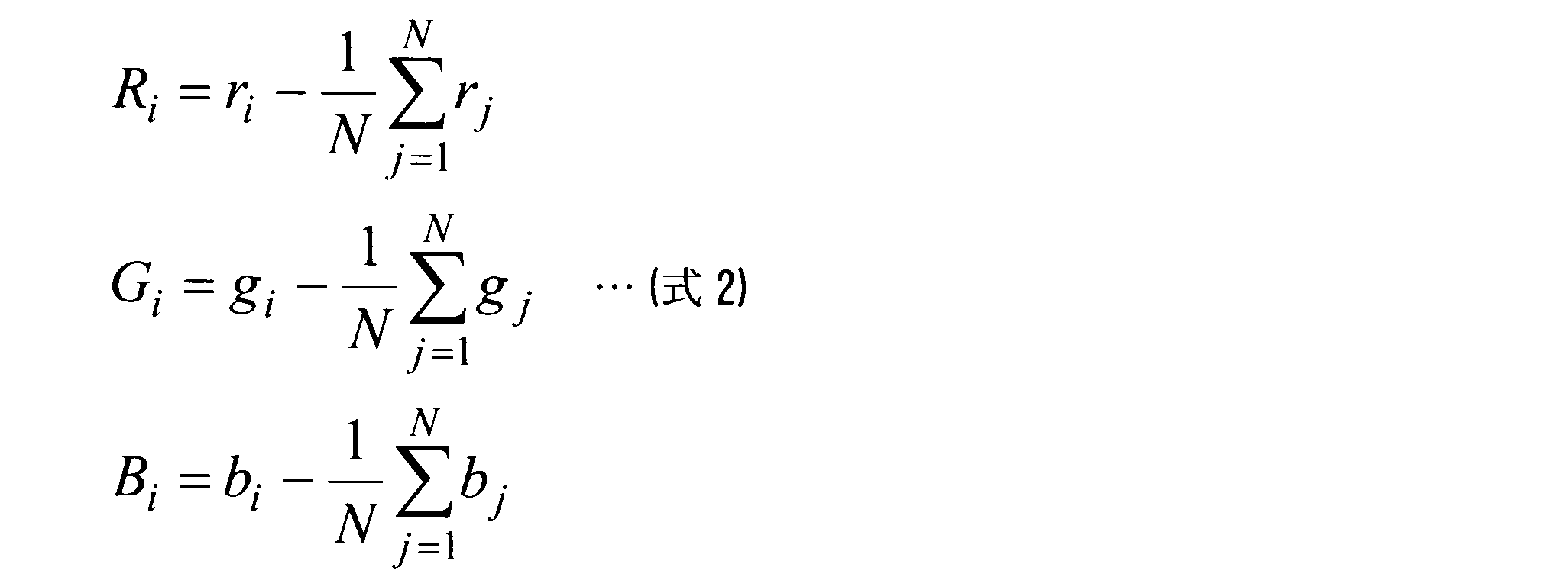
続いて、行列Pは転置行列Ptとの積を行列Aとして算出する(式3)。tは転置操作を表す。

このとき、行列A は行と列の数がいずれも分離された信号の要素数m である対称行列となる。よって、行列A を次式(式4)のように行列の積に分解することができる。

ただし、U およびVはmxmの直交行列、Σは行列Aの特異値σi(1 ≦ i ≦ rankA) を降順に並べたmxm の対角行列を表す。特異値σiは、At Aの固有値λiの平方である。具体的な手順は、まずAt Aの固有値を求め、特異値を算出する。次に、直交行列U 及びV はその定義からUt U = IおよびVt V = I であることを利用して(I は単位行列)、(式5)が得られる。

よって、次式(式6)で示すようにV の列ベクトルvi はAt A の固有値σi
2に対応する固有ベクトルとして求められる。なお、前述の量子化手段102における量子化パラメータを、当該空間軸における情報量に対応している当該固有値σi
2に応じて定めるようにしてもよい。

最後に、直交行列Vt は写像係数として符号化対象画素Qに適用し、写像画素信号Q'を算出する(式7)。

また、逆写像手段160,260で用いる写像係数は直交行列Uで与えられ、次式(式8)で写像画素信号Q'から画素信号Qを算出する。この際さらに、(式2)の逆の操作で平均がゼロではないようにすることで、最終的な画素信号を求める。すなわち、写像係数においては(式2)の平均をシフトさせる情報も含ませておくものとする。

例えば、図3の(2)の例であれば行列PをブロックA2の画素信号より求め、符号化対象画素Qの存在するブロックB0に適用することでその写像画素信号Q'が得られることとなる。
1…画像符号化装置、101…変換手段、102…量子化手段、103…符号化手段、104…(符号化側)逆量子化手段、105…(符号化側)逆変換手段、106…(符号化側)加算手段、107…差分手段、108…予測手段、109…(符号化側)補償手段、110…(符号化側)メモリ、150…(符号化側)写像手段、160…(符号化側)逆写像手段、2…画像復号装置、203…復号手段、204…(復号側)逆量子化手段、205…(復号側)逆変換手段、206…(復号側)加算手段、209…(復号側)補償手段、210…(復号側)メモリ、250…(復号側)写像手段、260…(復号側)逆写像手段
Claims (10)
- 所定の色空間で構成された符号化対象画素の画素信号を、信号間の相関を低減させる空間に写像した写像画素信号の形で単位ブロック毎に符号化する画像符号化装置であって、
符号化対象の画素信号に対して、その信号間の相関を低減させる写像係数を符号化済みの画素信号より算出して適用し、写像画素信号となす写像手段と、
符号化済み画素信号の写像画素信号より、符号化対象の写像画素信号を予測する予測情報を決定する予測手段と、
当該予測情報に基づいて符号化対象の写像画素信号の予測信号を生成する補償手段と、
当該符号化対象の写像画素信号とその予測信号との間で差分処理を行って予測残差信号となす差分手段と、
当該予測残差信号を直交変換して変換係数となす変換手段と、当該変換係数を前記写像係数に応じて量子化して量子化値となす量子化手段と、
当該量子化値及び前記予測情報を符号化する符号化手段と、
当該量子化値を逆量子化して変換係数となす逆量子化手段と、当該変換係数を逆直交変換して予測残差信号となす逆変換手段と、
当該予測残差信号と前記予測信号とを加算して符号化済みの写像画素信号となす加算手段と、
当該符号化済みの写像画素信号に前記写像係数を逆写像として適用して符号化済みの画素信号となす逆写像手段と、を備え、
前記写像手段は前記予測情報が参照する領域を含む所定領域における符号化済み画素信号より前記写像係数を算出すると共に、該写像係数を前記符号化対象の画素信号に対して適用する際に併せて当該参照する所定領域の符号化済み画素信号に適用し、
前記予測手段は当該適用された写像係数による前記所定領域の符号化済みの写像画素信号より、符号化対象の写像画素信号を予測することを特徴とする画像符号化装置。 - 前記写像手段が、主成分分析に基づいて前記写像係数を算出することを特徴とする請求項1に記載の画像符号化装置。
- 前記量子化手段が、写像画素信号の各空間の量子化パラメータを、各空間の主成分分析における固有値に基づいて定めることを特徴とする請求項2に記載の画像符号化装置。
- 前記予測手段は、所定の画面内予測方式における予測モードを決定することで予測情報を決定し、
前記写像手段は、前記所定の画面内予測方式における各予測モードに対して、当該予測モードが参照画素として定める領域を含んだ符号化済みの単位ブロックより写像係数を算出し、当該写像係数を前記符号化対象の画素信号及び当該参照画素の領域に適用し、
前記予測手段は、前記適用された写像係数による当該参照画素の領域の写像画素信号より、符号化対象の写像画素信号を予測する予測情報を決定することを特徴とする請求項1ないし3のいずれかに記載の画像符号化装置。 - 前記写像手段は、前記所定の画面内予測方式における各予測モードに対して、当該予測モードが参照画素として定める領域を含んだ符号化済みの単位ブロックと所定基準で画素分布が同一である符号化済み画素の領域と、当該単位ブロックと、から写像係数を算出し、当該写像係数を符号化対象の画素信号及び当該参照画素の領域に適用することを特徴とする請求項4に記載の画像符号化装置。
- 前記写像手段は、領域分割によって前記所定基準で画素分布が同一である符号化済み画素の領域を定めることを特徴とする請求項5に記載の画像符号化装置。
- 前記予測手段は、前記所定の画面内予測方式における各予測モードの中から、符号化コストを最小にする予測モードを前記予測情報として決定することを特徴とする請求項4ないし6のいずれかに記載の画像符号化装置。
- 前記予測手段が、画面間予測によって参照フレーム及び該参照フレームにおける参照ブロックを決定することで予測情報を決定し、
前記写像手段は、前記参照フレームにおいて前記参照ブロックを内部に含む所定のブロックより写像係数を算出することを特徴とする請求項1ないし7のいずれかに記載の画像符号化装置。 - 前記写像手段が、前記写像係数を算出するのに用いる領域が平坦な場合に当該算出を省略して所定の写像係数を利用する、又は、前記写像係数を算出するのに用いる領域が平坦な場合が符号化対象のブロック単位で連続する場合に最初のブロックにつき算出した写像係数を以降のブロックに対する写像係数に流用することを特徴とする請求項1ないし8のいずれかに記載の画像符号化装置。
- 請求項1ないし9のいずれかに記載の画像符号化装置により符号化された情報を前記所定の色空間で構成された画素信号へと単位ブロック毎に復号する画像復号装置であって、
前記符号化された量子化値及び予測情報を復号する復号手段と、
当該量子化値を逆量子化して変換係数となす復号側逆量子化手段と、当該変換係数を逆直交変換して予測残差信号となす復号側逆変換手段と、
復号済みの画素信号より得られる写像画素信号と、前記予測情報と、から復号対象の画素信号に対する写像画素信号の予測信号を生成する復号側補償手段と、
当該予測信号と前記予測残差信号とを加算して復号済みの写像画素信号となす復号側加算手段と、
前記予測情報が参照する領域を含む所定領域における復号済みの画素信号より前記写像係数を算出する復号側写像手段と、
当該算出された写像係数を前記復号済みの写像画素信号に対して逆写像として適用し、復号済みの画素信号となす復号側逆写像手段と、を備え、
前記復号側写像手段は前記写像係数を前記所定領域の復号済みの画素信号に適用することで、前記復号側補償手段が前記予測信号を生成する際に前記予測情報と併せて利用する、前記復号済みの画素信号より得られる写像画素信号となすことを特徴とする画像復号装置。
Priority Applications (1)
| Application Number | Priority Date | Filing Date | Title |
|---|---|---|---|
| US14/386,905 US9088798B2 (en) | 2012-03-26 | 2013-03-18 | Image encoding device and image decoding device |
Applications Claiming Priority (2)
| Application Number | Priority Date | Filing Date | Title |
|---|---|---|---|
| JP2012069240A JP5796899B2 (ja) | 2012-03-26 | 2012-03-26 | 画像符号化装置及び画像復号装置 |
| JP2012-069240 | 2012-03-26 |
Publications (1)
| Publication Number | Publication Date |
|---|---|
| WO2013146405A1 true WO2013146405A1 (ja) | 2013-10-03 |
Family
ID=49259666
Family Applications (1)
| Application Number | Title | Priority Date | Filing Date |
|---|---|---|---|
| PCT/JP2013/057620 Ceased WO2013146405A1 (ja) | 2012-03-26 | 2013-03-18 | 画像符号化装置及び画像復号装置 |
Country Status (3)
| Country | Link |
|---|---|
| US (1) | US9088798B2 (ja) |
| JP (1) | JP5796899B2 (ja) |
| WO (1) | WO2013146405A1 (ja) |
Cited By (2)
| Publication number | Priority date | Publication date | Assignee | Title |
|---|---|---|---|---|
| GB2533111A (en) * | 2014-12-09 | 2016-06-15 | Gurulogic Microsystems Oy | Encoder, decoder and method for images, video and audio |
| GB2533109A (en) * | 2014-12-09 | 2016-06-15 | Gurulogic Microsystems Oy | Encoder, decoder and method for data |
Families Citing this family (5)
| Publication number | Priority date | Publication date | Assignee | Title |
|---|---|---|---|---|
| US10542265B2 (en) * | 2014-09-09 | 2020-01-21 | Dolby Laboratories Licensing Corporation | Self-adaptive prediction method for multi-layer codec |
| JP6317272B2 (ja) * | 2015-02-10 | 2018-04-25 | 日本電信電話株式会社 | 映像符号化ストリーム生成方法、映像符号化ストリーム生成装置及び映像符号化ストリーム生成プログラム |
| US10163030B2 (en) * | 2016-05-20 | 2018-12-25 | Gopro, Inc. | On-camera image processing based on image activity data |
| US11412260B2 (en) * | 2018-10-29 | 2022-08-09 | Google Llc | Geometric transforms for image compression |
| US10841617B2 (en) | 2018-11-27 | 2020-11-17 | Semiconductor Components Industries, Llc | Methods and apparatus for successive intra block prediction |
Citations (3)
| Publication number | Priority date | Publication date | Assignee | Title |
|---|---|---|---|---|
| JPH0723232A (ja) * | 1993-06-24 | 1995-01-24 | Fujitsu Ltd | カラー画像符号化方式 |
| JPH07154605A (ja) * | 1993-11-25 | 1995-06-16 | Oki Electric Ind Co Ltd | カラー画像処理方法 |
| JPH08186817A (ja) * | 1994-12-28 | 1996-07-16 | Sony Corp | 動画像圧縮装置とその方法 |
Family Cites Families (9)
| Publication number | Priority date | Publication date | Assignee | Title |
|---|---|---|---|---|
| CN1640144A (zh) * | 2002-02-28 | 2005-07-13 | 皇家飞利浦电子股份有限公司 | 对数字彩色视频序列进行编码和解码的方法和设备 |
| US6646578B1 (en) * | 2002-11-22 | 2003-11-11 | Ub Video Inc. | Context adaptive variable length decoding system and method |
| EP1538826A3 (en) * | 2003-12-05 | 2007-03-07 | Samsung Electronics Co., Ltd. | Color transformation method and apparatus |
| KR100703740B1 (ko) * | 2004-10-21 | 2007-04-05 | 삼성전자주식회사 | 다 계층 기반의 모션 벡터를 효율적으로 부호화하는 방법및 장치 |
| KR101246915B1 (ko) * | 2005-04-18 | 2013-03-25 | 삼성전자주식회사 | 동영상 부호화 또는 복호화 방법 및 장치 |
| JP5227987B2 (ja) | 2010-03-10 | 2013-07-03 | 日本放送協会 | 符号化装置、復号装置及びプログラム |
| US20120236931A1 (en) * | 2010-12-23 | 2012-09-20 | Qualcomm Incorporated | Transform coefficient scan |
| US9490839B2 (en) * | 2011-01-03 | 2016-11-08 | Qualcomm Incorporated | Variable length coding of video block coefficients |
| US20130003859A1 (en) * | 2011-06-30 | 2013-01-03 | Qualcomm Incorporated | Transition between run and level coding modes |
-
2012
- 2012-03-26 JP JP2012069240A patent/JP5796899B2/ja active Active
-
2013
- 2013-03-18 WO PCT/JP2013/057620 patent/WO2013146405A1/ja not_active Ceased
- 2013-03-18 US US14/386,905 patent/US9088798B2/en not_active Expired - Fee Related
Patent Citations (3)
| Publication number | Priority date | Publication date | Assignee | Title |
|---|---|---|---|---|
| JPH0723232A (ja) * | 1993-06-24 | 1995-01-24 | Fujitsu Ltd | カラー画像符号化方式 |
| JPH07154605A (ja) * | 1993-11-25 | 1995-06-16 | Oki Electric Ind Co Ltd | カラー画像処理方法 |
| JPH08186817A (ja) * | 1994-12-28 | 1996-07-16 | Sony Corp | 動画像圧縮装置とその方法 |
Non-Patent Citations (1)
| Title |
|---|
| HARUHISA KATO ET AL.: "Improved Video Coding Method Based on Adaptive Basis Functions for Transforming Intra Prediction Error in H.264", THE JOURNAL OF THE INSTITUTE OF IMAGE INFORMATION AND TELEVISION ENGINEERS, vol. 65, no. 2, 1 February 2011 (2011-02-01), pages 229 - 234 * |
Cited By (4)
| Publication number | Priority date | Publication date | Assignee | Title |
|---|---|---|---|---|
| GB2533111A (en) * | 2014-12-09 | 2016-06-15 | Gurulogic Microsystems Oy | Encoder, decoder and method for images, video and audio |
| GB2533109A (en) * | 2014-12-09 | 2016-06-15 | Gurulogic Microsystems Oy | Encoder, decoder and method for data |
| GB2533111B (en) * | 2014-12-09 | 2018-08-29 | Gurulogic Microsystems Oy | Encoder, decoder and method for images, video and audio |
| GB2533109B (en) * | 2014-12-09 | 2018-11-28 | Gurulogic Microsystems Oy | Encoder, decoder and method for data |
Also Published As
| Publication number | Publication date |
|---|---|
| JP5796899B2 (ja) | 2015-10-21 |
| US9088798B2 (en) | 2015-07-21 |
| JP2013201639A (ja) | 2013-10-03 |
| US20150049956A1 (en) | 2015-02-19 |
Similar Documents
| Publication | Publication Date | Title |
|---|---|---|
| RU2699256C1 (ru) | Устройство кодирования изображений, устройство декодирования изображений, способ кодирования изображений, способ декодирования изображений и устройство прогнозирования изображений | |
| US8111914B2 (en) | Method and apparatus for encoding and decoding image by using inter color compensation | |
| JP5796899B2 (ja) | 画像符号化装置及び画像復号装置 | |
| JP5372911B2 (ja) | フレーム内コーディングのための画素ごとの重み付け | |
| JP7612777B2 (ja) | ブロックベース予測 | |
| JP5421757B2 (ja) | 画像符号化装置 | |
| JP7665822B2 (ja) | イントラ予測を用いた符号化 | |
| JP2006203909A (ja) | マクロブロックをイントラ符号化するための予測モードを選択する方法、ビデオデータのマクロブロックに対して少なくとも一つの予測モードを選択するための方法、予測モードの選択を可能にするためにコンピュータ可読媒体に実装されたコンピュータプログラム製品、および複数の予測モードでデータを符号化するためのエンコーダ | |
| CN101449588B (zh) | 用于视频压缩的空间稀疏性诱导瞬时预测 | |
| CN105284111A (zh) | 运动图像编码装置、运动图像解码装置、运动图像编码方法、运动图像解码方法、及程序 | |
| JP2008306720A (ja) | 照度補償方法及び装置、これを利用した映像の符号化、復号化方法及び装置 | |
| JP7806328B2 (ja) | 4:4:4のクロマフォーマット及びシングルツリーの場合のすべてのチャネルに対するmip | |
| JP2023053272A (ja) | 画像符号化装置、画像復号装置、及びプログラム | |
| JP5909149B2 (ja) | 色変換装置、符号化器および復号器ならびにそれらのプログラム | |
| US20170006290A1 (en) | Video encoding device and video encoding method | |
| JP2006174454A (ja) | 画像データの空間予測装置及び方法、それを利用した符号化装置及び方法、画像データの空間予測補償装置及び方法、それを利用した復号化装置及び方法 | |
| KR20190052022A (ko) | 인트라 기반의 로컬 인터-계층 예측을 위한 방법 | |
| JP4726047B2 (ja) | 画像符号化装置 | |
| EP4546776A1 (en) | Image encoding device and image decoding device based on ai, and image encoding and decoding method using same | |
| KR20080018469A (ko) | 영상 변환 방법 및 장치, 역변환 방법 및 장치 | |
| KR20130046377A (ko) | 화소 블록 코딩 및 재구성 방법 및 대응 장치 | |
| JP2022087262A (ja) | 画像復号装置及び画像復号方法 | |
| JP5328629B2 (ja) | エンコーダおよび画像変換装置 | |
| WO2013038888A1 (ja) | 画像符号化装置及び画像復号装置 | |
| KR20130029026A (ko) | 픽셀 블록을 코딩하고 재구성하기 위한 방법 및 대응하는 디바이스들 |
Legal Events
| Date | Code | Title | Description |
|---|---|---|---|
| 121 | Ep: the epo has been informed by wipo that ep was designated in this application |
Ref document number: 13769222 Country of ref document: EP Kind code of ref document: A1 |
|
| WWE | Wipo information: entry into national phase |
Ref document number: 14386905 Country of ref document: US |
|
| NENP | Non-entry into the national phase |
Ref country code: DE |
|
| 122 | Ep: pct application non-entry in european phase |
Ref document number: 13769222 Country of ref document: EP Kind code of ref document: A1 |