WO2013146082A1 - 情報処理システム、情報処理方法、情報処理装置およびその制御方法と制御プログラム - Google Patents
情報処理システム、情報処理方法、情報処理装置およびその制御方法と制御プログラム Download PDFInfo
- Publication number
- WO2013146082A1 WO2013146082A1 PCT/JP2013/055547 JP2013055547W WO2013146082A1 WO 2013146082 A1 WO2013146082 A1 WO 2013146082A1 JP 2013055547 W JP2013055547 W JP 2013055547W WO 2013146082 A1 WO2013146082 A1 WO 2013146082A1
- Authority
- WO
- WIPO (PCT)
- Prior art keywords
- device connection
- mobile terminal
- user
- information processing
- instruction information
- Prior art date
Links
Images


Classifications
-
- H—ELECTRICITY
- H04—ELECTRIC COMMUNICATION TECHNIQUE
- H04N—PICTORIAL COMMUNICATION, e.g. TELEVISION
- H04N7/00—Television systems
- H04N7/14—Systems for two-way working
- H04N7/15—Conference systems
-
- H—ELECTRICITY
- H04—ELECTRIC COMMUNICATION TECHNIQUE
- H04L—TRANSMISSION OF DIGITAL INFORMATION, e.g. TELEGRAPHIC COMMUNICATION
- H04L12/00—Data switching networks
- H04L12/02—Details
- H04L12/16—Arrangements for providing special services to substations
- H04L12/18—Arrangements for providing special services to substations for broadcast or conference, e.g. multicast
- H04L12/1813—Arrangements for providing special services to substations for broadcast or conference, e.g. multicast for computer conferences, e.g. chat rooms
- H04L12/1818—Conference organisation arrangements, e.g. handling schedules, setting up parameters needed by nodes to attend a conference, booking network resources, notifying involved parties
-
- H—ELECTRICITY
- H04—ELECTRIC COMMUNICATION TECHNIQUE
- H04W—WIRELESS COMMUNICATION NETWORKS
- H04W4/00—Services specially adapted for wireless communication networks; Facilities therefor
- H04W4/50—Service provisioning or reconfiguring
-
- H—ELECTRICITY
- H04—ELECTRIC COMMUNICATION TECHNIQUE
- H04W—WIRELESS COMMUNICATION NETWORKS
- H04W76/00—Connection management
- H04W76/10—Connection setup
-
- H—ELECTRICITY
- H04—ELECTRIC COMMUNICATION TECHNIQUE
- H04W—WIRELESS COMMUNICATION NETWORKS
- H04W8/00—Network data management
- H04W8/18—Processing of user or subscriber data, e.g. subscribed services, user preferences or user profiles; Transfer of user or subscriber data
-
- H—ELECTRICITY
- H04—ELECTRIC COMMUNICATION TECHNIQUE
- H04W—WIRELESS COMMUNICATION NETWORKS
- H04W8/00—Network data management
- H04W8/22—Processing or transfer of terminal data, e.g. status or physical capabilities
Definitions
- the present invention relates to a technology for connecting a device to a mobile terminal.
- Patent Document 1 discloses a technology for executing a corresponding device driver in a server when a device is connected to a thin client.
- the server starts a service triggered by the connection of the device, and the connection of the device cannot be predicted.
- An object of the present invention is to provide a technique for solving the above-described problems.
- an information processing apparatus provides: Device connection prediction means for predicting device connection to a mobile terminal; Device connection instruction information transmitting means for transmitting device connection instruction information for instructing the user to connect the device predicted by the device connection prediction means, to a portable terminal carried by the user via the network; Is provided.
- a method for controlling an information processing apparatus includes: A device connection prediction step for predicting device connection to the mobile terminal; Device connection instruction information transmission step for transmitting device connection instruction information for instructing the user to be the device connection predicted in the device connection prediction step to a mobile terminal carried by the user via the network; including.
- a control program for an information processing apparatus provides: A device connection prediction step for predicting device connection to the mobile terminal; Device connection instruction information transmission step for transmitting device connection instruction information for instructing the user to be the device connection predicted in the device connection prediction step to a mobile terminal carried by the user via the network; Is executed on the computer.
- a system comprising a mobile terminal carried by a user and an information processing apparatus connected to the mobile terminal via a network
- the information processing apparatus is Device connection prediction means for predicting device connection to a mobile terminal
- Device connection instruction information transmitting means for transmitting device connection instruction information for instructing a user to be a device connection predicted by the device connection prediction means, to a portable terminal carried by the user via a network
- the mobile terminal is Device connection instruction information receiving means for receiving the device connection instruction information transmitted from the device connection instruction information transmitting means;
- Device connection means capable of connecting a device according to the device connection instruction information; Is provided.
- the method according to the present invention comprises: An information processing method for an information processing system having a device connection means capable of connecting a device and comprising a portable terminal carried by a user and an information processing apparatus connected to the portable terminal via a network, A device connection prediction step in which the information processing apparatus predicts device connection to a mobile terminal; and A device connection instruction information transmitting step in which the information processing apparatus transmits device connection instruction information for instructing the user to make the device connection predicted in the device connection prediction step to a portable terminal carried by the user via the network; , A device connection instruction information receiving step in which the mobile terminal receives the device connection instruction information transmitted in the device connection instruction information transmitting step; including.
- the user can be instructed to predict the device connection to the mobile terminal and to obtain the predicted device connection.
- connection connector DB which concerns on 2nd Embodiment of this invention.
- connection connector DB which concerns on 2nd Embodiment of this invention.
- block diagram which shows the hardware constitutions of the cloud server which concerns on 2nd Embodiment of this invention.
- indication table which concerns on 2nd Embodiment of this invention.
- flowchart which shows the process sequence of the cloud server which concerns on 2nd Embodiment of this invention.
- connection device selection process which concerns on 2nd Embodiment of this invention.
- block diagram which shows the hardware constitutions of the portable terminal which concerns on 2nd Embodiment of this invention.
- connection device DB which concerns on 3rd Embodiment of this invention.
- connection connector DB which concerns on 3rd Embodiment of this invention.
- indication table which concerns on 3rd Embodiment of this invention.
- process sequence of the cloud server which concerns on 3rd Embodiment of this invention.
- process sequence of the connection device selection process which concerns on 3rd Embodiment of this invention. It is a figure explaining operation
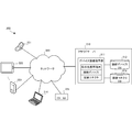
- the information processing apparatus 100 is an apparatus that issues a device connection instruction to the mobile terminal 111.
- the information processing apparatus 100 includes a device connection prediction unit 101 and a device connection instruction information transmission unit 102.
- the device connection prediction unit 101 predicts device connection to the mobile terminals 111 and 112.
- the device connection instruction information transmission unit 102 transmits device connection instruction information 102a instructing the user 120 to connect the device predicted by the device connection prediction unit 101 to the portable terminal 111 carried by the user 120 via the network 130. To do.
- device connection to the mobile terminal can be prepared in advance by predicting and instructing connection of the device to the mobile terminal.
- the information processing system predicts the occurrence of various events, selects and determines a device connection related to the event, and issues a device connection instruction to the user's mobile terminal in advance.
- the present embodiment by predicting an event occurrence and selecting and instructing a device for the user to respond to, it is possible to prepare a device connection to a mobile terminal corresponding to the event occurrence in advance.
- a history of devices used at the time of an event is accumulated and a device to be connected is selected.
- a specific connection device may be stored corresponding to the event.
- FIG. 2 is a diagram for explaining the operation of the information processing system 200 according to the present embodiment.
- the upper part of FIG. 2 is an operation for inquiring Mr. A whether or not to participate in the video conference when the event of starting the video conference occurs.
- the cloud server 210 as an information processing apparatus needs to connect a keyboard and a mouse as connection devices to the mobile terminal 220 in order for Mr. A to participate in this video conference using the mobile terminal 220 as a tablet. To be notified.
- the cloud server 210 selects and starts a program necessary for controlling the keyboard 221 and the mouse 222. Then, the cloud server 210 connects the mobile terminal 220, the keyboard 221, and the mouse 222 to a virtual PC (personal computer), thereby allowing Mr. A to participate in the video conference.
- a virtual PC personal computer
- the middle part of Fig. 2 is an operation to ask Mr. B for a comment when an event occurs that Mr. B who does not participate in the video conference wants a comment.
- the cloud server 210 that is the information processing apparatus notifies that the keyboard needs to be connected to the mobile terminal 230 as a connection device in order for Mr. B to comment on this video conference using the mobile terminal 230 that is a smartphone. .
- the cloud server 210 selects and starts a program necessary for controlling the keyboard 231. Then, the cloud server 210 connects the mobile terminal 230 and the keyboard 231 to a virtual PC (personal computer), and allows Mr. B to input a comment using the keyboard 231 while viewing the screen of the mobile terminal 230.
- a virtual PC personal computer
- the lower part of Fig. 2 is an operation to notify Mr. C of the event that the oil price has risen.
- the cloud server 210 that is the information processing apparatus notifies that it is necessary to connect a large display as a connection device to the mobile terminal 240 in order for Mr. C to obtain this notification using the mobile terminal 240 that is a mobile phone. To do.
- the cloud server 210 selects and starts a program necessary for controlling the large display 241. Then, the cloud server 210 displays detailed oil price fluctuation information on the large display 241 via Mr. C's mobile terminal 240.
- FIG. 3 is a block diagram illustrating a configuration of the information processing system 200 according to the present embodiment.
- the information processing system 200 includes a cloud server 210 connected via a network 330 and mobile terminals 321 to 325 (including a router 325) as shown in FIG.
- a cloud server 210 connected via a network 330 and mobile terminals 321 to 325 (including a router 325) as shown in FIG.
- USB devices can be connected to the portable terminals 321 to 325.
- the cloud server 210 is connected to a connection device DB 312 that accumulates a history of connection devices connected to the mobile terminal in association with the event that has occurred, and a specific connection connector (corresponding to a mobile terminal when there is one connector). And a connection connector DB 313 that stores a history of connection devices. And it has the device connection instruction
- the device connection instructing unit 311 stores the instructed portable terminal, the connection device, and the connection connector as device saving instruction information.
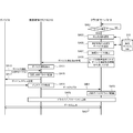
- FIG. 4A is a sequence diagram illustrating an operation procedure for connecting a device to a mobile terminal instructed to connect in the information processing system 200 according to the present embodiment.
- the cloud server 210 waits for an event to occur in step S401. If an event occurrence is detected, the process proceeds to step S403, and a process corresponding to the occurred event is selected. Next, in step S405, a device necessary for the selected process is selected. In step S407, a user who connects the selected device is selected. In step S409, device connection instruction information for the mobile terminal possessed by the selected user is generated and transmitted to the mobile terminals 220 to 240, which are tablets, smartphones, and mobile phones.
- the mobile terminals 220 to 240 that have received the device connection instruction information issue a device connection instruction in step S411 (see FIG. 2).
- the portable terminals 220 to 240 activate the general-purpose USB driver in step S415.
- step S417 device addresses by the portable terminals 220 to 240 are set.
- step S419 a device descriptor is acquired. The acquired descriptor is transferred to the cloud server 210 in step S421.
- step S423 the cloud server 210 that has acquired the descriptor activates a USB device driver that drives the connection device determined from the descriptor.
- step S425 a driver application for connecting the cloud server 210 and the connected device via the mobile terminals 220 to 240 is activated.
- step S427 data input / output between the cloud server 210 and the connected device via the portable terminals 220 to 240 is realized.
- FIG. 4B is a sequence diagram showing an operation procedure for connecting a device to a mobile terminal different from the mobile terminal instructed to connect in the information processing system 200 according to the present embodiment.
- steps similar to those in FIG. 4A are denoted by the same step numbers and description thereof is omitted.
- step S451 the user's portable terminal that notifies the device connection instruction information is selected.
- step S453 a connector for connecting the selected device is selected.
- a mobile terminal for notifying device connection instruction information, a connection connector for connecting a device (corresponding to a mobile terminal when there is one connector), and a device connection instruction for the mobile terminal of the selected user in step S455 Generate and send information.
- This device connection instruction information includes connection connector information.
- device connection instruction information is notified to the portable terminal a. It is assumed that the device connection instruction information includes an instruction to connect the output device B to the portable terminal b and connect the input device A to the router c.
- step S457 the notifying user's mobile terminal a issues a device connection instruction including a connection connector.
- the output device B is connected to the mobile terminal b in step S461.
- the portable terminal a acquires device information (descriptor) in step S463.
- device information In FIG. 4B, a detailed USB driver protocol is omitted to avoid complexity.
- the device information is transferred to the cloud server 210.
- the cloud server 210 activates a device driver that drives the output device B in step S467.
- a driver application for connecting the cloud server 210 and the output device B via the portable terminal b is activated.
- step S471 the input device A is connected to the router c.
- step S473 the router c notifies the cloud server 210 of the device connection.
- step S475 the cloud server 210 requests device information (descriptor) from the input device A via the router c according to the USB protocol.
- the input device A returns device information via the router c in step S477.
- step S479 the cloud server 210 activates a device driver that drives the input device A.
- step S ⁇ b> 481 input data from the input device A is acquired by the cloud server 210 via the router c. If necessary, the output data is sent to the output device B via the portable terminal b in step S483 after data processing. For example, if the input device A is a DVD drive and the output device B is a display, a DVD video is output to the display.
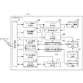
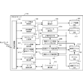
- FIG. 5 is a block diagram showing a functional configuration of the cloud server 210 according to the present embodiment.
- the cloud server 210 includes a communication control unit 501 that communicates with the mobile terminals 220 to 240 and 321 to 325 via the network 330.
- a user information receiving unit 502 receives user information such as a user ID and authentication information from a message received from the portable terminal in the communication control unit 501.
- the terminal information receiving unit 503 receives terminal information such as a portable terminal ID and authentication information. Based on the user information and the terminal information, the user registration unit 504 registers the user in the user registration DB 505 (see FIG. 7).
- the event acquisition unit 506 functions as an event detection unit that acquires an event from the outside via the communication control unit 501 or an event that occurs inside the cloud server 210.
- the transmission destination selection unit 507 refers to the user registration DB 505 to select a transmission destination portable terminal that transmits device connection instruction information.
- the connection device selection unit 508 includes a connection device DB 312 (see FIGS. 9A and 9B) and a device DB 510 (FIG. 8). Based on the above, a connection device for instructing device connection is selected. On the other hand, the connection connector selection unit 509 selects a connection connector that is a connection destination of the connection device included in the device connection instruction based on the connection connector DB 313 (see FIG. 10).
- connection device selected by the connection device selection unit 508 and the connection connector selected by the connection connector selection unit 509 are stored in the device connection instruction table 311a of the device connection instruction unit 311. Then, the device connection instruction unit 311 transmits the device connection instruction information generated based on the device connection instruction table 311a to the transmission destination mobile terminal selected by the transmission destination selection unit 507.
- the device information receiving unit 512 receives device information (descriptor) of the device connected via the mobile terminal.
- the device driver execution unit 513 drives the connected device.
- the data transmission / reception unit 514 performs data transmission / reception with the connected device via the portable terminal.
- FIG. 6 is a block diagram showing a functional configuration of the mobile terminals 220 to 240 and 321 to 324 according to the present embodiment.
- the portable terminal 220 will be described as a representative.
- the portable terminal 220 of this embodiment has a USB connector 601 for connecting a USB device.
- a general-purpose USB driver 602 for acquiring a descriptor of a device connected to the USB connector 601 is provided.
- the mobile terminal 220 has a USB device input data transmission unit 603 for IP encapsulation of input data from the USB device and transmits the input data to the cloud server 210 via the communication control unit 605 via the IP network.
- the mobile terminal 220 receives the output data to the USB device received from the cloud server 210 via the IP network via the communication control unit 605, receives the USB device output data that is unencapsulated and passed to the general-purpose USB driver 602. Part 604.
- the communication control unit 605 is a control unit that controls communication with the cloud server 210 or another portable terminal via the network.
- image and data communication are communicated by 4G / 3G, and voice communication such as a mobile phone or a smartphone is communicated by WiFi.
- the mobile terminal 220 includes a transmission unit 613 and a reception unit 614 that transmit data different from the USB device via the communication control unit 605.
- the mobile terminal 220 includes an operation unit 609 including a touch panel and a keyboard, and an input / output unit 610.
- the input / output unit 610 includes a display unit 611 that displays data received by the receiving unit 614 and an audio input / output unit 612 that inputs and outputs audio.
- FIG. 7 is a diagram showing a configuration of the user registration DB 505 according to the present embodiment.
- the user registration DB 505 is not limited to the configuration shown in FIG.
- the user registration DB 505 is associated with the user ID 701, and includes a portable terminal ID 702, a portable terminal model 703, a communication performance 704, a device connector 705 that the portable terminal has, a mounted device driver 706, a voice communication method 707, and a data communication method. 708 and the like are stored.
- FIG. 8 is a diagram showing a configuration of the device DB 510 according to the present embodiment.
- the device DB 510 is not limited to the configuration shown in FIG.
- the device DB 510 stores a device model 802, an input device or output device type 803, a connection connector 804 included in the device, a communication method 805, a device capability 806, and the like in association with the device ID 801.
- the connection connector 804 corresponds to the communication method 805, only one of them may be stored.
- connection device DB 9A and 9B are diagrams illustrating the configuration of the connection device DB 312 according to the present embodiment. Note that the connection device DB 312 is not limited to the configurations of FIGS. 9A and 9B.
- FIG. 9A is a diagram showing a partial configuration of the connection device DB 312 according to the present embodiment.
- FIG. 9A is a database 910 that accumulates a history of how the cloud server 210 has performed from the contents of the event that has occurred.
- the database 910 stores a first response process 902, a second response process 903,... In association with the event content 901.
- the storage order may be the order of appearance. Moreover, you may memorize
- FIG. 9B is a diagram showing a partial configuration of the connection device DB 312 according to the present embodiment.
- FIG. 9B is a database 920 that accumulates a history of which connected device the user has connected from the corresponding process selected from FIG. 9A or which connected device the cloud server 210 has instructed to connect.
- the database 920 stores the connection device 922 in association with the handling process 921.
- Each connection device 922 stores a usage rate 923 indicating the number of times the device is used with respect to the number of times the corresponding process 921 appears.
- the model 924 included in each connection device 922 is stored.
- the connection connector 925, the connector-equipped device 926, and the cumulative satisfaction 927 of all registered users so far are stored.
- the connector-equipped device 926 includes a mobile terminal, a router, and the like.
- FIG. 10 is a diagram illustrating a configuration of the connection connector DB 313 according to the present embodiment. Note that the connection connector DB 313 is not limited to the configuration of FIG.
- connection connector DB 313 stores the current location 1003 measured by the owner 1002, GPS (Global Positioning System), etc., and an area 1004 including the current location, such as a room, in association with the connector-mounted device 1001. Then, the connection connector 1005, the first connection device and its connection count 1006, the second connection device and its connection count 1007,... Are stored in association with each connector-equipped device 1001.
- the connector-equipped device 1001 includes a mobile terminal, a router, and the like.
- FIG. 11 is a block diagram illustrating a hardware configuration of the cloud server 210 according to the present embodiment.
- a CPU 1110 is an arithmetic control processor, and implements each functional component of the cloud server 210 of FIG. 5 by executing a program.
- the ROM 1120 stores fixed data and programs such as initial data and programs.
- the communication control unit 501 is a communication control unit, and in this embodiment, communicates with the mobile terminals 220, 240 and 321 to 324 and the router 325 via the network 330.
- the CPU 1110 is not limited to one, and may be a plurality of CPUs or may include a GPU (GraphicsGraphProcessingGraphUnit) for image processing.
- the RAM 1140 is a random access memory that the CPU 1110 uses as a work area for temporary storage.
- the RAM 1140 has an area for storing data necessary for realizing the present embodiment.
- the notification destination user ID 1141 is an identifier of a communication destination user who transmits device connection instruction information.
- the notification destination terminal ID 1142 is an identifier of a communication destination portable terminal.
- the device connection instruction table 311a is a table for generating device connection instruction information to be transmitted to the mobile terminal indicated by the notification destination terminal ID 1142.
- the device connection information 1143 is device connection history information including user satisfaction and the like retrieved from the connection device DB 312 and the connection connector DB 313 in order to generate device connection instruction information (see FIG. 12).
- the device data 1144 is data for inputting / outputting to / from the device.
- the transmission / reception data 1145 is a message transmitted / received via the communication control unit 501 with the portable terminal.
- the storage 1150 stores a database, various parameters, or the following data or programs necessary for realizing the present embodiment.
- the user registration DB 505 is the database shown in FIG.
- the device DB 510 is the database shown in FIG.
- the connected device DB 312 is the database shown in FIGS. 9A and 9B.
- the connection connector DB 313 is the database shown in FIG.
- the storage 1150 stores the following programs.
- the cloud server control program 1151 is a program that controls the entire cloud server 210.
- the device connection instruction module 1152 is a module that generates and transmits device connection instruction information for the mobile terminal in the cloud server control program 1151.
- the device connection instruction module 1152 includes connection device selection processing (see FIG. 14).
- the connected device control module 1253 is a module that controls connected devices in the cloud server control program 1151.
- the connection device control module 1153 includes a USB device driver and a driver application for connecting the cloud server 210 and the mobile terminal 220 to the device in cooperation with the driver application of the mobile terminal.
- FIG. 11 shows data and programs related to the present embodiment, and general-purpose data and programs in the cloud server are not shown.
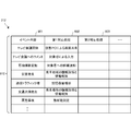
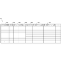
- FIG. 12 is a diagram showing a configuration of the device connection instruction table 311a according to the present embodiment.
- the device connection instruction table 311a stores a corresponding process selected in association with the event content 1201. Each corresponding process stores the connection device 1203 selected as necessary for connection.
- the model 1204, the connection connector 1205, and the connector mounted device 1206 are stored in association with each connection device 1203.
- the connector-equipped device 1206 includes a mobile terminal, a router, and the like.
- a notification destination terminal ID 1207 for transmitting device connection instruction information and a notification destination user ID 1208 are stored in association with each event content 1201 and the corresponding processing 1202.
- a notification destination terminal ID 1207 for transmitting device connection instruction information and a notification destination user ID 1208 are stored in association with each event content 1201 and the corresponding processing 1202.
- FIG. 12 although one notification destination terminal is used, a plurality of notification destination terminals may be provided.
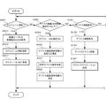
- FIG. 13 is a flowchart showing a processing procedure of the cloud server 210 according to the present embodiment. This flowchart is executed by the CPU 1110 of FIG. 11 using the RAM 1140, and implements the functional configuration unit of FIG. The flowchart of FIG. 13 starts when an event occurrence, device connection notification, data input / output request, or the like occurs in the cloud server 210.
- step S1311 the cloud server 210 determines whether an event occurrence has been detected (or whether an event occurrence has been acquired). In step S1321, the cloud server 210 determines whether a device connection notification is received from the mobile terminal. In step S1331, the cloud server 210 determines whether to request input data from a device connected to the mobile terminal. In step S1341, the cloud server 210 determines whether to request data output to a device connected to the mobile terminal.
- step S1313 selects a corresponding process by referring to the connection device DB 312 from the content of the event that has occurred.
- step S1315 the cloud server 210 selects a mobile terminal that is a transmission destination of the generated device connection instruction information.
- step S1317 the cloud server 210 refers to the connection device DB 312 and the connection connector DB, selects a connection device, and executes connection device selection processing for generating device connection instruction information (see FIG. 14).
- step S1319 the cloud server 210 transmits the generated device connection instruction information to the transmission destination mobile terminal.
- the cloud server 210 proceeds to step S1323 and acquires device information (descriptor) of the device connected from the mobile terminal.
- the cloud server 210 acquires device information directly from a device connected via the mobile terminal.
- the cloud server 210 activates the corresponding device driver from the device information.
- the cloud server 210 activates a driver application for connecting the cloud server 210, the mobile terminal 220, and the connection device.
- the cloud server 210 proceeds to step S1333 and requests data input from the device connected to the mobile terminal. Subsequently, the cloud server 210 waits for reception of input data in step S1335. If the input data is received, the cloud server 210 proceeds to step S1337, uncensors the received data, and stores the input data.
- the cloud server 210 proceeds to step S1343 and acquires output data.
- the output data may be data generated by the cloud server 210 or data acquired by the cloud server 210 via another mobile terminal or from an external server.
- the cloud server 210 encapsulates the acquired data to generate transmission data, and transmits the transmission data to a device connected to the mobile terminal.
- the cloud server 210 waits for completion of reception from the portable terminal, and ends data output if transmission OK can be confirmed.
- FIG. 14 is a flowchart showing a processing procedure of the connected device selection processing S1317 according to the present embodiment.
- step S1401 the cloud server 210 selects an appropriate device candidate necessary for the selected handling process with reference to the connection device DB 312.
- step S1403 the cloud server 210 selects appropriate connection connector candidates that can be used in and around the transmission destination with reference to the connection connector DB 313.
- step S1405 the cloud server 210 selects a candidate for the combination of the selected appropriate connection device and connection connector with reference to the user satisfaction level or the like.
- step S1407 the cloud server 210 generates device connection instruction information to be notified to the mobile terminal from the selected candidate combination of the appropriate connection device and the connection connector.
- FIG. 15 is a block diagram showing a hardware configuration of the mobile terminals 220 to 240 and 321 to 324 according to the present embodiment. Since the configuration is the same, the portable terminal 220 will be described below as a representative.
- a CPU 1510 is a processor for arithmetic control, and implements each functional component of the mobile terminal 220 in FIG. 6 by executing a program.
- the ROM 1520 stores fixed data and programs such as initial data and programs.
- the communication control unit 605 is a communication control unit, and in the present embodiment, communicates with the cloud server 210 via a network. Note that the number of CPUs 1510 is not limited to one, and may be a plurality of CPUs or may include a GPU for image processing.
- the RAM 1540 is a random access memory that the CPU 1510 uses as a work area for temporary storage.
- the RAM 1540 has an area for storing data necessary for realizing the present embodiment.
- the user ID 1541 is an identifier of a user who is using the mobile terminal.
- the device connection instruction information 1542 is information instructing device connection received from the cloud server 210.
- the device connection flag 1543 is a flag indicating that a device is connected to the USB connector 601.
- the acquired descriptor 1544 is a descriptor acquired from the connected USB device.
- the device input / output packet 1545 is a packet input / output to / from the USB device.
- the server transmission / reception packet 1546 is a capsuled packet that is transmitted / received to / from the cloud server 210 via the communication control unit 605.
- Input / output data 1547 indicates input / output data input / output via the input / output interface 1560.
- the storage 1550 stores a database, various parameters, or the following data or programs necessary for realizing the present embodiment.
- the mobile terminal ID 1551 is an identifier of the mobile terminal.
- the storage 1550 stores the following programs.
- the mobile terminal control program 1552 is a control program that controls the entire mobile terminal 220.
- the device connection instruction module 1553 is a module that receives device connection instruction information from the cloud server 210 and displays it on the display unit 611 in the mobile terminal control program 1552.
- the connected device control module 1554 is a module that controls connected devices in the portable terminal control program 1552.
- the connection device control module 1653 includes a general-purpose USB driver or a driver application that links the cloud server 210 to the mobile terminal 220 in cooperation with the driver application of the cloud server 210.
- the input / output interface 1560 interfaces input / output data with input / output devices.
- the input / output interface 1560 is connected to an operation unit 609 including a display unit 611 and a touch panel.
- a voice input / output unit 612 such as a speaker or a microphone is connected.
- a GPS (Global Positioning System) position generation unit 1561, a camera 1562, and the like are connected. Then, the USB connector 601 is connected.
- FIG. 15 shows data and programs related to the present embodiment, and general-purpose data and programs in the mobile terminal are not shown.
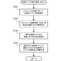
- FIG. 16 is a flowchart showing a processing procedure of the mobile terminals 220 to 240 and 321 to 324 according to the present embodiment. This flowchart is executed by the CPU 1510 using the RAM 1540, and implements each functional component of FIG. Note that the flowchart of FIG. 16 starts when an event such as a device connection instruction from the cloud server 210 in the portable terminal, a USB device connection, or a device input / output process occurs.
- an event such as a device connection instruction from the cloud server 210 in the portable terminal, a USB device connection, or a device input / output process occurs.
- step S ⁇ b> 1611 the mobile terminal determines whether or not device connection instruction information is received from the cloud server 210.
- step S1621 the mobile terminal determines whether the USB device is connected to the USB connector.
- step S1431 the mobile terminal determines whether the input / output processing of the connected device is performed.
- step S1613 the mobile terminal proceeds to step S1613 and notifies the device connection instruction information.
- the notification includes screen display and / or audio output.
- step S ⁇ b> 1615 the portable terminal waits for confirmation of reception of the user's device connection instruction information.
- the portable terminal transmits a receipt notification to the cloud server 210 in step S1617.
- This receipt confirmation is a process for preventing a delay in device connection due to the absence of the user who transmitted the device connection instruction information.
- the information processing system according to the present embodiment is different from the second embodiment in that the approach of the registered schedule is an event occurrence. Since other configurations and operations are the same as those of the second embodiment, the same configurations and operations are denoted by the same reference numerals, and detailed description thereof is omitted.
- the present embodiment by instructing the user to connect the device in response to the approach of the schedule, it is possible to prepare the device connection to the mobile terminal corresponding to the schedule in advance.
- FIG. 17 is a diagram for explaining the operation of the information processing system 1700 according to the present embodiment.
- FIG. 17 shows an operation in the case of processing an event occurrence of device preparation for holding a video conference that is registered in advance as a schedule.
- the schedule for the video conference on March 21 is registered from the mobile terminal 1720 which is Mr. A's smartphone.
- the schedule information includes, for example, a room name to be used (first meeting room), an agenda (smartphone development), and video conference participants (A, B,).
- the schedule is transmitted from the mobile terminal 1720 to the cloud server 1710 and registered in the schedule DB 1715 of the cloud server 1710. That is, the schedule DB 1715 functions as a schedule storage unit.
- an event occurs one week before the start of the video conference, the day before the video conference start, and 30 minutes before the start of the video conference.
- the mobile terminal 1720 which is Mr. A's smartphone in the upper right diagram, is notified whether or not a device that needs to be reserved has been reserved.
- necessary devices and their connection connectors are notified to the mobile terminal 1720, which is Mr. A's smartphone in the middle of the right diagram.
- the user B is notified of the necessary devices and their connection connectors to the mobile terminal 1730 which is Mr. B's smartphone in the lower part of the right figure.
- the mobile terminal 1730 which is Mr. B's smartphone in the lower part of the right figure.
- a participant here, Mr. B
- Mr. A the user of the cloud server
- the device connection instruction is given to the participant. Therefore, the notification is made to the portable terminal 1730 which is the smartphone of Mr. B who is the next participant.
- the projector 1731 is connected to the mobile terminal 1730 that is Mr. B's smartphone, and the keyboard 1742 and the mouse 1743 are connected to the mobile terminal 1740 that is Mr. C's tablet via the router 1741. Is done.
- the cloud server 1710 confirms connection of necessary devices, and runs a video conference program including a device driver, a driver application, a data processing application, and a WEB application on the virtual PC. Then, by connecting each device, preparation for the start of the video conference is completed, and the arrival of the participant is awaited.
- FIG. 18 is a block diagram illustrating a configuration of an information processing system 1700 according to the present embodiment.
- a video conference including a Tokyo headquarters conference room 1820 and a Nara laboratory conference room 1830 is assumed.
- the information processing system 1700 includes a cloud server 1710 connected via a network 1840, each mobile terminal (including a router) in the Tokyo head office conference room 1820, and each mobile terminal in the Nara laboratory conference room 1830. Have.
- the cloud server 1710 includes a schedule registration unit 1814 that registers a schedule instructed by the user in the schedule DB 1715.
- a connection device DB 1812 that accumulates a connection history for selecting a connection device corresponding to the schedule contents of the present embodiment, and a connection connector DB 1813 that accumulates a connection history for selecting a connection connector corresponding to the schedule contents.
- the connection device DB 1812 and the connection connector DB 1813 function as connection history storage means. And it has the device connection instruction
- the device connection instruction unit 1811 stores an instruction destination terminal to which device connection instruction information is transmitted, and a connection device and a connection connector that are device connection instruction information.
- a mobile terminal 1730 which is Mr. B's smartphone and a projector 1731 connected to the mobile terminal 1730 are arranged.
- a mobile terminal 1740 that is Mr. C's smartphone, and a keyboard 1742 and a mouse 1743 connected to the mobile terminal 1740 via the router 1741 are arranged.
- a video camera 1822 and a microphone and speaker 1823 are connected to the router 1821 provided in the conference room as a connection device.
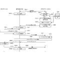
- FIG. 19 is a sequence diagram showing an operation procedure of the information processing system 1700 according to this embodiment.
- steps similar to those in FIG. 4A of the second embodiment are denoted by the same step numbers and description thereof is omitted.
- a schedule is input from A's mobile terminal 1720.
- the cloud server 1710 receives the schedule information from the portable terminal 1720, and registers the schedule in the schedule DB 1715 in step S1903. Thereafter, the cloud server 1710 manages the registered schedule and informs the user's mobile terminal of information related to the connected device in a timely manner.
- step S1911 it is determined whether it is the notification timing of the connected device. For example, one week before, the day before, 30 minutes before, etc. shown in FIG. Note that the notification timing may be unified in advance or set by the user. The operation procedure 30 minutes before in FIG. 17 will be described below.
- connection device and connection connector are selected.
- step S1913 it is determined whether or not Mr. A who registered the schedule participates. If Mr. A participates, the device connection instruction information is transmitted to the portable terminal 1720, and thereafter, preparation for device connection by Mr. A is performed.
- step S1921 the process proceeds to step S1921, and the next transmission destination of the device connection instruction information is selected. As the next transmission destination, other participants in the same schedule or a person close to Mr. A may be selected with reference to past participation history.
- step S1923 device connection instruction information is transmitted to the selected transmission destination portable terminal 1730 (in this example, Mr. B's smartphone).
- step S1925 the portable terminal 1730 receives the device connection instruction information and instructs Mr. B to connect the device.
- step S1931 each of the devices ac is connected to the participating mobile terminal 1730 and mobile terminal 1740 of C and the router 1741 of the conference room.
- step S1933 a notification of device connection is sent from each portable terminal and router to the cloud server 1710.
- step S1935 a virtual PC is generated and the video conference application is activated.
- screen sharing is also possible in the Nara Institute conference room in this example, which is a participating group in another location.
- steps S1937, S1939, and S1941 data input / output to the virtual PC is executed, and a video conference sharing the screen is realized.
- FIG. 20 is a block diagram illustrating a functional configuration of the cloud server 1710 according to the present embodiment.
- the same reference numerals are assigned to the same functional components as those in FIG. 5 of the second embodiment, and the description thereof will be omitted.
- the schedule receiving unit 2015 receives the schedule registration content received from the mobile terminal.
- the schedule registration content is sent to the schedule registration unit 1814 and registered in the schedule DB 1715 (see FIG. 21).
- the connected device DB 1812 accumulates the history of connected devices corresponding to the schedule contents (see FIG. 22).
- the connection connector DB 1813 accumulates connection connector history corresponding to the schedule content (see FIG. 23).
- the connected device notification timing detection unit 2006 detects the notification timing of the connected device based on the schedule information in the schedule DB 1715. Then, the connection device notification timing detection unit 2006 activates the transmission destination selection unit 507, the connection device selection unit 508, and the connection connector selection unit 509.
- the device connection instruction unit 1811 has a device connection instruction table 1811a (see FIG. 23), and stores the connection devices and connection connectors selected corresponding to the schedule contents. Then, the device connection instruction unit 1811 generates device connection instruction information and transmits the device connection instruction information to the transmission destination portable terminal selected by the transmission destination selection unit 507.
- FIG. 21 is a diagram showing a configuration of the schedule DB 1715 according to the present embodiment. Note that the schedule DB 1715 is not limited to FIG.
- the schedule DB 1715 stores the schedule content 2102 in association with the schedule date and time 2101.
- the interval of the date 2101 may be variable depending on the number of schedules.
- the instruction timing 2103 of the connected device and the registered user ID 2104 that registered the schedule are stored.
- the first place information 2105 including the first use place, the preparation manager, and the participant, the second place information 2106 including the second use place, the preparation manager, and the participant are stored.
- the location information may be one. From the place of use, it is possible to search for information such as device devices and routers deployed at the place.
- FIG. 22 is a diagram showing the configuration of the connection device DB 1812 according to this embodiment.
- the connection device DB 1812 is not limited to FIG.
- the connected device DB 1812 stores a connected device candidate 2203 in association with the schedule content 2201 and the connected device instruction timing 2202.
- the connection device candidate 2203 stores the first device, the second device,..., And the usage rate and user satisfaction of each device corresponding to this schedule are added. Then, the usage rate for the combination of devices and the user satisfaction are stored in association with each connected device candidate 2203.
- FIG. 23 is a diagram showing a configuration of the connection connector DB 1813 according to the present embodiment.
- the connection connector DB 1813 is not limited to FIG.
- connection connector DB 1813 stores the position coordinates 2302 and the connection connector 2303 that can be used at the target location in association with the target location 2301 included in the schedule information.
- the connection connector 2303 stores a first connection connector, a second connection connector,.
- Each connection connector includes information on the type and position, the number of connectors, and the current number of uses.
- connection connector DB1813 may be updated at any time, and when selecting a connection connector, it is separate from connection connector DB1813. , You may add.
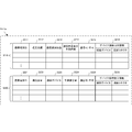
- FIG. 24 is a diagram showing a configuration of the device connection instruction table 2011a according to the present embodiment.
- the device connection instruction table 2011a stores schedule contents 2402 in association with the transmission timing 2401. Then, the device connection instruction information transmission destination 2403, the first device connection candidate 2404, the second device connection candidate 2405, ... are stored in association with each schedule content 2402. As each device connection candidate, at least one connection device candidate (only the first and second are shown in the figure) including the connection connector candidate is stored.
- connection device candidate may be added to each connection device candidate and device connection candidate.
- FIG. 25 is a flowchart showing the processing procedure of the cloud server 1710 according to this embodiment. This flowchart is executed by the CPU 1110 of FIG. 11 using the RAM 1140, and implements the functional configuration unit of FIG. In FIG. 25, the same processing as in FIG. 13 of the second embodiment is omitted, and the same step number is assigned to the same step, and the description is omitted.
- step S2511 the cloud server 1710 determines whether the schedule is registered from the mobile terminal. In step S2521, the cloud server 1710 determines whether it is the notification timing of the device connection instruction information.
- the cloud server 1710 proceeds to step S2513 and acquires the user ID and mobile terminal ID to be registered. Next, the cloud server 1710 acquires the schedule content in step S2515. In step S2517, the cloud server 1710 registers the acquired schedule in the schedule DB 1715.
- the cloud server 1710 proceeds to step S2523 and reads the schedule contents from the schedule DB 1715.
- the cloud server 1710 selects a mobile terminal that is the transmission destination of the device connection instruction information.
- the cloud server 1710 selects a connection device and a connection connector, and executes connection device selection processing for generating device connection instruction information (see FIG. 26).
- the cloud server 1710 transmits the generated device connection instruction information to the selected transmission destination mobile terminal.
- FIG. 26 is a flowchart showing the processing procedure of the connected device selection processing S2527 according to this embodiment.
- steps similar to those in FIG. 14 of the second embodiment are denoted by the same step numbers, and description thereof is omitted.
- step S2601 the cloud server 1710 selects necessary device candidates according to the schedule contents.
- step S2603 the cloud server 1710 selects a connection connector candidate at a schedule execution place or a connection connector candidate that can be used by connecting a connection device in the vicinity.
- the subsequent processing is the same as in FIG.
- the information processing system according to the present embodiment is different from the second embodiment in that the prediction of a change in communication capacity or communication amount is an event occurrence. Since other configurations and operations are the same as those of the second embodiment, the same configurations and operations are denoted by the same reference numerals, and detailed description thereof is omitted.
- a device connection to a mobile terminal corresponding to a communication state can be prepared in advance.
- FIG. 27 is a diagram for explaining the operation of the information processing system 2700 according to this embodiment.
- Communication failures include communication interruptions such as when a vehicle enters a tunnel, communication failures that occur in natural environments such as magnetic storms, connection failures due to relay station failures, communication capacity reduction, or communication volume increases. Etc. are included.
- a window 2723 is opened on the display screen 2722 of the mobile terminal 2720 in the upper center. In the window 2723, for example, a message “Communication failure occurs after 20 minutes.
- FIG. 27 shows a case where a keyboard 2741 and a mouse 2742 are connected to a USB connector of a display screen 2721 of a mobile terminal 2720 which is a smartphone via a router 2740 and a virtual PC of the cloud server 2710 is used.
- a large display 2750 is connected, or a connection is being made according to an instruction from the cloud server 1710.
- the communication amount prediction unit 2712 predicts the total communication amount or the average communication amount of all devices and predicts that a communication problem will occur in the communication capacity of the mobile terminal, it notifies the mobile terminal 2720 of this.
- a window 2728 is opened on the display screen 2727 of the portable terminal 2720 in the lower center. Then, in the window 2728, for example, a message “There is a possibility that the communication capacity is insufficient. Please connect the display to the shop terminal.” Is displayed, and the user can connect the large display to another mobile terminal. Prompt to connect. As shown in the lower right diagram, by connecting a large display 2750 to the USB connector of a portable terminal 2760 that is a nearby friend's tablet, communication failure of the portable terminal 2720 due to an increase in communication volume can be prevented in advance.
- (Operation procedure) 28A and 28B show an operation procedure of the information processing system 2700 according to this embodiment.
- the same step numbers are assigned to the same steps as those in FIGS. 4A and 4B of the second embodiment, and the description thereof is omitted.
- FIG. 28A is a sequence diagram showing an operation procedure when a communication failure occurrence is predicted in the information processing system 2700 according to the present embodiment.
- step S2811 communication between the cloud server 2710 and the portable terminal 2720 has been established, and in the portable terminal 2720, data processing is performed in step S2813.
- step S2817 the transmission destination of the device connection instruction information is selected.
- the transmission destination is the portable terminal 2720 in general. However, it can also be transmitted to other mobile terminals in the vicinity.
- step S2819 a connection device is selected with reference to the communication capacity DB 2816. Then, after the device connection instruction information is generated and transmitted to the mobile terminal 2720, the procedure from when the device (memory device in this example) is connected and becomes controllable from the cloud server 2710 is the same as that in FIG. 4A. is there.
- step S2827 data is downloaded from the cloud server 2710 to the memory device.
- the downloaded data is stored in the memory device in step S2829.
- step S2831 communication between the cloud server 2710 and the portable terminal 2720 is interrupted or the capacity becomes insufficient due to a communication failure.
- step S2833 data downloaded in advance to the memory device is read by the portable terminal 2720. Then, the data processing of the portable terminal 2720 is continued without being affected by the communication failure in step S2835.
- FIG. 28B is a sequence diagram showing an operation procedure when predicting an increase in communication amount in the information processing system 2700 according to the present embodiment.
- the same step number is attached to the same step as in FIG. 28A, and the description is omitted.
- step S2851 a new device is connected to the portable terminal 2720.
- step S2853 the device information of the connected device is transmitted from the portable terminal 2720 to the cloud server 2710.
- step S2855 an increase in the traffic volume is predicted with reference to the traffic volume DB 2817.
- step S2859 a connection connector for changing the connection of the device is selected in order to suppress an increase in communication volume.
- the new device is removed from the mobile terminal 2720 in step S2861.
- the mobile terminal 2760 is connected to another mobile terminal 2760.
- the portable terminal 2760 transmits the acquired device information to the cloud server 2710.
- the cloud server 2710 can input / output data between the device connected to the mobile terminal 2720 and the new device connected to the mobile terminal 2760 via the cloud server 2710 by connecting the new device to the virtual PC. Become.
- FIG. 29 is a block diagram showing a functional configuration of the cloud server 2710 according to the present embodiment.
- the same functional components as those in FIG. 5 of the second embodiment are denoted by the same reference numerals, and description thereof is omitted.
- the communication environment acquisition unit 2918 acquires communication environment information from a portable terminal or other communication device via the communication control unit 501.
- the communication environment information is stored in the communication capacity DB 2816 (see FIG. 30) and the communication amount DB 2817 (see FIG. 31) by the communication environment storage unit 2919.
- the event prediction unit 2906 includes a communication environment prediction unit 2711 and a traffic amount prediction unit 2712.
- the communication environment prediction unit 2711 refers to the communication capacity DB 2816, functions as a communication capacity prediction unit that predicts the communication capacity, and predicts the occurrence of a communication failure.
- the communication amount prediction unit 2712 refers to the communication amount DB 2817 to predict an increase in communication amount. Then, the event prediction unit 2906 predicts a communication failure of the communication environment prediction unit 2711 and an increase in communication amount of the communication amount prediction unit 2712 as an event occurrence.
- the device connection instruction unit 2911 is a device connection instruction table 2911a (see FIG. 32).
- the device connection instruction information including the connection device and the connection connector is generated and transmitted to the selected mobile terminal.
- FIG. 30 is a diagram showing a configuration of the communication capacity DB 2816 according to the present embodiment. Note that the configuration of the communication capacity DB 2816 is not limited to FIG.
- the communication capacity DB 2816 includes a database 3010 that accumulates a history of communication capacity decrease in a specific specific place or region, and a database 3020 that records a communication failure that occurs unexpectedly.
- the database 3010 stores road information 3012 associated with a road, a communication capacity decrease state 3013, a maximum duration 3014 in which the communication capacity decrease continues, and a maximum range 3015 in which the communication capacity decrease extends in association with the area information 3011. To do.
- the database 3020 stores, in association with the regional information 3021, a maximum range 3022 to which a communication failure extends, a communication failure numerical value 3023, a communication failure start time 3024, and a predicted continuous time 3025.
- FIG. 31 is a diagram showing the configuration of the communication volume DB 2817 according to this embodiment. Note that the configuration of the communication volume DB 2817 is not limited to FIG.
- the traffic volume DB 2817 includes a database 3110 for storing a history of traffic volume corresponding to each device, and a database 3120 for storing a history of historical volume when the devices are used in combination.
- the database 3110 stores a maximum communication amount 3112 and an average communication amount 5113 in association with each device 3111.
- the database 3120 stores a maximum communication amount 3122 and an average communication amount 5123 in association with each device combination 3121.
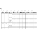
- FIG. 32 is a diagram showing the configuration of the device connection instruction table 2911a according to this embodiment.
- the device connection instruction table 2911a includes a table 3210 used in the operation of FIG. 28A and a table 3220 used in the operation of FIG. 28B.
- the table 3210 stores device connection instruction information 3216 including a current position 3212, a communication use state 3213, a communication capacity decrease predicted time 3214, a communication enable / disable 3215, and a connection device and a connection connector in association with the mobile terminal ID 3211. .
- the table 3220 is associated with the mobile terminal ID 3221 and includes device connection instruction information 3226 including a communication capacity 3222 allowed by the mobile terminal, a connection device 3223, a predicted communication amount 3224, communication enable / disable 3225, a connection device and a connection connector.
- device connection instruction information 3226 including a communication capacity 3222 allowed by the mobile terminal, a connection device 3223, a predicted communication amount 3224, communication enable / disable 3225, a connection device and a connection connector.
- FIG. 33 is a flowchart showing the processing procedure of the cloud server 2710 according to this embodiment. This flowchart is executed by the CPU 1110 of FIG. 11 using the RAM 1140, and implements the functional configuration unit of FIG. In FIG. 33, the same processing as in FIG. 13 of the second embodiment is deleted.
- the cloud server 2710 determines whether or not a communication failure is predicted in step S3311. In addition, the cloud server 2710 determines in step S3321 whether or not an increase in communication amount is predicted.
- the cloud server 2710 proceeds to step S3313 and selects a portable terminal that is the destination of device connection instruction information.
- step S3315 the cloud server 2710 generates device connection instruction information based on the communication capacity DB 2816.
- step S3317 the cloud server 2710 transmits device connection instruction information to the selected transmission destination mobile terminal.
- the cloud server 2710 proceeds to step S3323 and selects a portable terminal that is the destination of device connection instruction information. Next, the cloud server 2710 generates device connection instruction information based on the communication amount DB 2817 in step S3325. In step S3317, the cloud server 2710 transmits device connection instruction information to the selected transmission destination mobile terminal.
- the information processing system according to the present embodiment is different from the second to fourth embodiments in that the program after device connection is determined and executed based on the history of combinations of devices and use programs. Since other configurations and operations are the same as those of the second to fourth embodiments, the same configurations and operations are denoted by the same reference numerals, and detailed description thereof is omitted.
- the information processing apparatus selects and executes a program appropriate for the connected device, thereby receiving a service for using the connected device without user operation. Can do.
- ⁇ Information processing system With reference to FIGS. 34 and 35, the configuration and operation of the information processing system according to the present embodiment will be described.
- a device is connected from the event prediction according to the schedule of the third embodiment, and an appropriate program is selected and activated, whereby the connected device is processed by the cloud server 3410 without any operation by the user.
- An example is shown.
- an example of collecting periodic patient biological information (pulse, blood pressure, body temperature, etc.) using a mobile terminal by connecting a sensor device will be described. However, it is not limited to this.
- FIG. 34 is a diagram for explaining the operation of the information processing system 3400 according to the present embodiment.
- the measurement schedule of the biological information of Mr. A who is the patient is registered from the mobile terminal 3420 which is Mr. A's smartphone.
- the schedule information for example, pulse measurement is set at intervals of 3 hours, blood pressure is measured at 6 o'clock every morning, and body temperature is measured at waking up and before going to bed.
- the schedule is transmitted from the mobile terminal 3420 to the cloud server 3410 and registered in the schedule DB 3415 of the cloud server 3410.
- an event occurs when the pulse time measurement time approaches in the set schedule.
- a message “Pulse measurement time is approaching. Please connect a pulse sensor.” Is displayed on the screen of mobile terminal 3420, which is Mr. A's smartphone.
- a USB pulse sensor 3421 that can be connected to the USB connector of portable terminal 3420 nearby, it is connected to portable terminal 3420 and pulse measurement is performed.
- the USB pulse sensor 3421 is the USB pulse sensor that Mr. A is always using or the same model.
- a program including the device driver must be searched and installed.
- a program corresponding to the connected USB pulse sensor 3421 is automatically selected and installed based on the program combination accumulation DB 3418 of the cloud server 3410. Therefore, no user operation is required.
- the USB pulse sensor is not nearby and the HDMI pulse sensor 3431 is nearby.
- the pulse of Mr. A can be measured by connecting the HDMI pulse sensor 3431 to the portable terminal 3430.
- the mobile terminal 3430 does not measure the pulse, and simply connecting does not work.
- the WEB application and the like to be performed must be searched and installed by the user.
- the program is automatically installed and executed with reference to the history stored in the program combination storage DB 3418 of the cloud server 3410. Therefore, no user operation is required.
- FIG. 35 is a sequence diagram showing an operation procedure after device connection in the information processing system 3400 according to the present embodiment.
- steps similar to those in FIG. 4A of the second embodiment are denoted by the same reference numerals, and description thereof is omitted.
- step S3501 the cloud server 3410 that has acquired the descriptor from the device connected to the mobile terminal 3420 refers to the program combination accumulation DB 3418, and selects a program appropriate for processing using the connected device.
- a device address by the cloud server 3410 is set in step S3505.
- the selected WEB application is activated.
- step S3511 the cloud server 3410 sends a data input request to the portable terminal 3420 in step S3511.
- step S3513 the portable terminal 3420 acquires input data by bulk transfer (IN).
- step S3515 the portable terminal 3420 performs IP encapsulation on the input data and transmits the input data to the cloud server 3410.
- step S3517 the cloud server 3410 stores input data. If data processing is necessary, a data processing application is activated in step S3519. A data processing application is also selected in step S3501.
- the cloud server 3410 acquires output data in step S3521.
- the cloud server 3410 transmits a data output request to the portable terminal 3420 together with output data.
- the portable terminal 3420 sends the unencapsulated output data to the device by bulk transfer (OUT).
- FIG. 36 is a block diagram showing a functional configuration of the cloud server 3410 according to the present embodiment.
- the same functional components as those in FIG. 5 of the second embodiment or FIG. 20 of the third embodiment are denoted by the same reference numerals, and description thereof is omitted.
- the schedule DB 3415 registers a schedule related to biological information measurement of the present embodiment (see FIG. 37).
- the descriptor receiving unit 3621 receives the descriptor of the connected device transmitted by the mobile terminal.
- the device determination unit 3622 determines a connected device from the received descriptor and the contents of the device DB 510.
- the combination selection unit 3623 includes an execution program table 3623a (see FIG. 39), and selects a combination of execution programs with reference to the program combination accumulation DB 3418 (see FIG. 38).
- the program execution unit 3624 executes the selected program.
- the programs to be selected and executed include a USB device driver, a driver application (driver application in the figure), and a WEB application (WEB application in the figure).
- FIG. 37 is a diagram showing a configuration of the schedule DB 3415 according to the present embodiment. Note that the schedule DB 3415 is not limited to FIG. Also, the same reference numerals are assigned to the same columns as in FIG. 21 of the third embodiment.
- the schedule DB 3415 stores the schedule content 3702 in association with the event occurrence date and time 2101 of instructing the user's portable terminal to connect the device according to the schedule.
- the connected device instruction timing 3703, the user ID 2104 that registered the schedule, and the patient ID 3705 to be measured are stored.
- FIG. 38 is a diagram showing the configuration of the program combination accumulation DB 3418 according to this embodiment. Note that the program combination accumulation DB 3418 is not limited to FIG.
- the program combination accumulation DB 3418 stores the connection device 3803 in the connection history in association with the connection terminal 3802 of the portable terminal 3801 and the portable terminal 3801.
- a combination of the used driver 3804 and the used application 3805 is stored in association with each connected device 3803.
- the driver used is a device driver.
- Use applications include a driver application, a data processing application, and a WEB application.
- Use application 3805 may also store different combinations.
- the number of uses 3806, the cumulative satisfaction 3807 of all users, the average satisfaction 3808, and the maximum / minimum satisfaction 3809 are stored. Furthermore, other indices can be stored.
- the association selection unit 3623 refers to these usage count 3806, cumulative satisfaction 3807 of all users, average satisfaction 3808, and maximum / minimum satisfaction 3809, and various combinations that can be used as a combination with connected devices. Points are given to the program, and the program with the highest point is automatically selected and installed.
- FIG. 39 is a diagram showing a configuration of the execution program table 3623a according to the present embodiment.
- the execution program table 3623a stores the cloud server selection program 3905 selected by the patient ID 3903, the connection device 3904, and the cloud server 3410 in association with the mobile terminal ID 3901 and the user ID 3902.
- the cloud server selection program 3905 is an appropriate combination of a device driver, a driver application, and a WEB application, and is automatically executed by the cloud server 3410. Therefore, the user can use the connected device without any operation.
- FIG. 40 is a flowchart showing the processing procedure of the cloud server 3410 according to this embodiment. This flowchart is executed by the CPU 1110 of FIG. 11 using the RAM 1140, and implements the functional configuration unit of FIG. 40 starts when an event such as packet transmission / reception in the cloud server 3410 occurs.
- step S4011 the cloud server 3410 determines whether a packet is received.
- step S4031 the cloud server 3410 determines whether it is a packet transmission. If the packet is received, the cloud server 3410 proceeds to step S4013, performs unencapsulation, and determines whether or not the descriptor of the connected device is received. If it is not a descriptor, the cloud server 3410 determines that input data has been received.
- the cloud server 3410 proceeds to step S4015 and acquires device information of the connected device from the descriptor.
- step S4017 the cloud server 3410 searches the program combination accumulation DB 3418 based on the device information and selects a program that causes the device to operate appropriately.
- step S4019 the cloud server 3410 activates the selected device driver. A device address by the cloud server 3410 is set for the device.
- the cloud server 3410 activates the selected driver application in step S4021. If necessary, the cloud server 3410 downloads an application corresponding to the mobile terminal 3420. Furthermore, the cloud server 3410 activates the selected WEB application in step S4023.
- the cloud server 3410 proceeds to step S4025 and acquires the input data.
- the cloud server 3410 performs data processing as necessary.
- a data processing application may also be selected in step S4017.
- the cloud server 3410 stores input data from the device.
- the cloud server 3410 proceeds to step S4033 and acquires output data.
- the cloud server 3410 outputs the output data encapsulated to the device. That is, the cloud server 3410 passes output data to the device driver, the driver application, and the WEB application.
- the information processing system according to this embodiment is different from the second to fifth embodiments in that the mobile terminal communicates with a plurality of communication paths when the communication amount or the communication capacity is predicted and the bandwidth is not sufficient.
- the same configurations and operations are denoted by the same reference numerals, and detailed description thereof is omitted.
- the bandwidth is automatically changed by predicting the communication amount or the communication capacity, it is possible to perform the device processing in which the user is connected without being aware of the change of the communication amount or the communication capacity.
- FIG. 41 is a sequence diagram illustrating an operation procedure when the mobile terminal communicates via a plurality of communication paths in the information processing system 4100 according to the present embodiment.
- step S4101 the cloud server 4110 and the device 4130 perform data input / output via the mobile terminal 4120.
- step S4111 the communication amount and the communication capacity are predicted.
- step S4113 it is determined whether the communication band of the portable terminal 4120 is sufficient as a result of the prediction of the traffic and the communication capacity. If the communication bandwidth is sufficient, data input / output is measured as it is.
- the cloud server 4110 predicts that the communication band of the mobile terminal 4120 is not sufficient compared to the traffic, the cloud server 4110 proceeds to Step 4115 and selects an appropriate communication method of the mobile terminal 4120.
- the communication method of the portable terminal 4120 is, for example, whether to communicate by 4G / 3G alone, to communicate by WiFi alone, or to communicate by expanding the communication band by using 4G / 3G + WiFi together.
- step S4117 the communication method is changed to the selected communication method.
- step S4119 the first channel driver application of 4G / 3G is activated.
- step S4121 the second channel driver application which is EiFi is activated.
- step S423 the data input / output between the device 4130 and the portable terminal 4120 in step S4123 is separated by the portable terminal 4120.
- step S4125 broadband communication using 4G / 3G + WiFi is performed.
- the communication separation may be performed in units of devices as long as a plurality of devices are connected. Alternatively, input data and output data may be separated. Alternatively, image data and audio data may be separated.
- the information processing system according to the present embodiment is different from the second to sixth embodiments in that the mobile terminal cannot acquire device information when the device is connected to the mobile terminal. Since other configurations and operations are the same as those in the second to sixth embodiments, the same configurations and operations are denoted by the same reference numerals, and detailed description thereof is omitted.
- the cloud server since the cloud server controls the connected device even when the mobile terminal cannot acquire the device information, it is possible to control whatever device is connected.
- FIG. 42 is a sequence diagram illustrating an operation procedure when the mobile terminal cannot acquire device information in the information processing system 4200 according to the present embodiment.
- step S4201 the device is connected to the portable terminal 4220 with an RS232 cable and a USB cable.
- the portable terminal 4220 activates the general-purpose USB driver to acquire the device descriptor.
- step S419 the portable terminal 4220 times out without acquiring the descriptor.
- step S4209 the portable terminal 4220 stops the process of the general-purpose USB driver.
- step S4211 control of the device connected to the cloud server 4210 is requested.
- step S4213 the cloud server 4210 that has received the request for device control sequentially operates drivers that can operate the connected device, and determines the connected device. Specifically, first, a set of drivers is activated in step S4215. In step S4217, the device is accessed using the activated driver. In step S4219, it is determined whether the device can be controlled. If it is determined that control is possible, device information is acquired by the driver in step S4221.
- drivers include drivers that can convert between RS232 and USB, as well as drivers that can drive devices.
- an appropriate program including a device driver, a driver application, a data processing application, and a WEB application is selected with reference to the program combination storage D3418 in step S3501.
- the present invention may be applied to a system composed of a plurality of devices, or may be applied to a single device. Furthermore, the present invention can also be applied to a case where a control program that realizes the functions of the embodiments is supplied directly or remotely to a system or apparatus. Therefore, in order to realize the functions of the present invention on a computer, a control program installed in the computer, a medium storing the control program, and a WWW (World Wide Web) server that downloads the control program are also included in the scope of the present invention. include.
Abstract
Description
携帯端末に対するデバイス接続を予測するデバイス接続予測手段と、
前記デバイス接続予測手段が予測したデバイスの接続となるようユーザに指示するデバイス接続指示情報を、ネットワークを介してユーザが携帯する携帯端末に送信するデバイス接続指示情報送信手段と、
を備える。
携帯端末に対するデバイス接続を予測するデバイス接続予測ステップと、
前記デバイス接続予測ステップにおいて予測したデバイス接続となるようユーザに指示するデバイス接続指示情報を、ネットワークを介してユーザが携帯する携帯端末に送信するデバイス接続指示情報送信ステップと、
を含む。
携帯端末に対するデバイス接続を予測するデバイス接続予測ステップと、
前記デバイス接続予測ステップにおいて予測したデバイス接続となるようユーザに指示するデバイス接続指示情報を、ネットワークを介してユーザが携帯する携帯端末に送信するデバイス接続指示情報送信ステップと、
をコンピュータに実行させる。
ユーザが携帯する携帯端末と、該携帯端末とネットワークを介して接続する情報処理装置とを備える情報処理システムであって、
前記情報処理装置が、
携帯端末に対するデバイス接続を予測するデバイス接続予測手段と、
前記デバイス接続予測手段が予測したデバイス接続となるようユーザに指示するデバイス接続指示情報を、ネットワークを介して前記ユーザが携帯する携帯端末に送信するデバイス接続指示情報送信手段と、
を備え、
前記携帯端末が、
前記デバイス接続指示情報送信手段から送信された前記デバイス接続指示情報を受信するデバイス接続指示情報受信手段と、
前記デバイス接続指示情報に従うデバイスを接続可能なデバイス接続手段と、
を備える。
デバイスを接続可能なデバイス接続手段を有し、ユーザが携帯する携帯端末と、該携帯端末とネットワークを介して接続する情報処理装置とを備える情報処理システムの情報処理方法であって、
前記情報処理装置が、携帯端末に対するデバイス接続を予測するデバイス接続予測ステップと、
前記情報処理装置が、前記デバイス接続予測ステップにおいて予測したデバイス接続となるようユーザに指示するデバイス接続指示情報を、ネットワークを介して前記ユーザが携帯する携帯端末に送信するデバイス接続指示情報送信ステップと、
前記携帯端末が、前記デバイス接続指示情報送信ステップにおいて送信された前記デバイス接続指示情報を受信するデバイス接続指示情報受信ステップと、
を含む。
本発明の第1実施形態としての情報処理装置100について、図1を用いて説明する。情報処理装置100は、携帯端末111へのデバイスの接続指示を行なう装置である。
次に、本発明の第2実施形態に係る情報処理システムについて説明する。本実施形態に係る情報処理システムは、種々のイベントの発生を予測し、そのイベントに関連するデバイス接続を選定、決定して、予めユーザの携帯端末にデバイス接続指示をする。
まず、図2、図3、図4Aおよび図4Bを参照して、本実施形態に係る情報処理システムの構成および動作を説明する。
図2は、本実施形態に係る情報処理システム200の動作を説明する図である。
図3は、本実施形態に係る情報処理システム200の構成を示すブロック図である。
図4Aは、本実施形態に係る情報処理システム200において、接続指示された携帯端末にデバイスを接続する動作手順を示すシーケンス図である。
図5は、本実施形態に係るクラウドサーバ210の機能構成を示すブロック図である。
に基づいて、デバイス接続指示を行なう接続デバイスを選定する。一方、接続コネクタ選定部509は、接続コネクタDB313(図10参照)に基づいて、デバイス接続指示に含まれる接続デバイスの接続先である接続コネクタを選定する。
図6は、本実施形態に係る携帯端末220~240、321~324の機能構成を示すブロック図である。以下、いずれも同様の構成であるので、携帯端末220を代表させて説明する。
図7は、本実施形態に係るユーザ登録DB505の構成を示す図である。なお、ユーザ登録DB505は、図7の構成に限定されない。
図8は、本実施形態に係るデバイスDB510の構成を示す図である。なお、デバイスDB510は、図8の構成に限定されない。
図9Aおよび図9Bは、本実施形態に係る接続デバイスDB312の構成を示す図である。なお、接続デバイスDB312は、図9Aおよび図9Bの構成に限定されない。
図10は、本実施形態に係る接続コネクタDB313の構成を示す図である。なお、接続コネクタDB313は、図10の構成に限定されない。
図11は、本実施形態に係るクラウドサーバ210のハードウェア構成を示すブロック図である。
図12は、本実施形態に係るデバイス接続指示テーブル311aの構成を示す図である。
図13は、本実施形態に係るクラウドサーバ210の処理手順を示すフローチャートである。このフローチャートは、図11のCPU1110がRAM1140を使用して実行し、図5の機能構成部を実現する。なお、図13のフローチャートは、クラウドサーバ210にイベント発生、デバイス接続通知、データ入出力要求などが発生したことによりスタートする。
図14は、本実施形態に係る接続デバイス選定処理S1317の処理手順を示すフローチャートである。
図15は、本実施形態に係る携帯端末220~240、321~324のハードウェア構成を示すブロック図である。なお、同様の構成であるので、以下、携帯端末220を代表させて説明する。
図16は、本実施形態に係る携帯端末220~240、321~324の処理手順を示すフローチャートである。このフローチャートは、CPU1510によりRAM1540を使用して実行され、図6の各機能構成部を実現する。なお、図16のフローチャートは、携帯端末におけるクラウドサーバ210からのデバイス接続指示、USBデバイスの接続、あるいは、デバイスの入出力処理などのイベントが発生したことによりスタートする。
次に、本発明の第3実施形態に係る情報処理システムについて説明する。本実施形態に係る情報処理システムは、上記第2実施形態と比べると登録したスケジュールの接近をイベント発生とした点で異なる。その他の構成および動作は、第2実施形態と同様であるため、同じ構成および動作については同じ符号を付してその詳しい説明を省略する。
図17および図18を参照して、本実施形態に係る情報処理システムの構成および動作を説明する。
図17は、本実施形態に係る情報処理システム1700の動作を説明する図である。図17は、あらかじめスケジュール登録されたテレビ会議開催のためのデバイス準備というイベント発生を処理する場合の動作を示す。
図18は、本実施形態に係る情報処理システム1700の構成を示すブロック図である。図18においては、東京本社会議室1820と奈良研究所会議室1830とを含むテレビ会議を仮定する。
図19は、本実施形態に係る情報処理システム1700の動作手順を示すシーケンス図である。なお、図19において、第2実施形態の図4Aと同様のステップには同じステップ番号を付して、説明を省略する。
図20は、本実施形態に係るクラウドサーバ1710の機能構成を示すブロック図である。なお、図20において、第2実施形態の図5と同様の機能構成部には同じ参照番号を付して、説明は省略する。
図21は、本実施形態に係るスケジュールDB1715の構成を示す図である。なお、スケジュールDB1715は、図21に限定されない。
図22は、本実施形態に係る接続デバイスDB1812の構成を示す図である。なお、接続デバイスDB1812、図22に限定されない。
図23は、本実施形態に係る接続コネクタDB1813の構成を示す図である。なお、接続コネクタDB1813、図23に限定されない。
図24は、本実施形態に係るデバイス接続指示テーブル2011aの構成を示す図である。
図25は、本実施形態に係るクラウドサーバ1710の処理手順を示すフローチャートである。このフローチャートは、図11のCPU1110がRAM1140を使用して実行し、図20の機能構成部を実現する。なお、図25において、第2実施形態の図13と同様の処理は省略し、同様のステップには同じステップ番号を付して、説明は省略する。
図26は、本実施形態に係る接続デバイス選定処理S2527の処理手順を示すフローチャートである。なお、図26において、第2実施形態の図14と同様のステップには同じステップ番号を付して、説明は省略する。
次に、本発明の第4実施形態に係る情報処理システムについて説明する。本実施形態に係る情報処理システムは、上記第2実施形態と比べると、通信容量や通信量の変化の予測をイベント発生とした点で異なる。その他の構成および動作は、第2実施形態と同様であるため、同じ構成および動作については同じ符号を付してその詳しい説明を省略する。
図27、図18Aおよび図18Bを参照して、本実施形態に係る情報処理システムの構成および動作を説明する。
図27は、本実施形態に係る情報処理システム2700の動作を説明する図である。
図28Aおよび図28Bに、本実施形態に係る情報処理システム2700の動作手順を示す。なお、図28Aおよび図28Bにおいて、第2実施形態の図4Aや図4Bと同様のステップには同じステップ番号を付して、説明は省略する。
図29は、本実施形態に係るクラウドサーバ2710の機能構成を示すブロック図である。なお、図29において、第2実施形態の図5と同様の機能構成部には同じ参照番号を付して、説明を省略する。
を有し、接続デバイスと接続コネクタを含むデバイス接続指示情報を生成して、選定した送信先の携帯端末に送信する。
図30は、本実施形態に係る通信容量DB2816の構成を示す図である。なお、通信容量DB2816の構成は、図30に限定されない。
図31は、本実施形態に係る通信量DB2817の構成を示す図である。なお、通信量DB2817の構成は、図31に限定されない。
図32は、本実施形態に係るデバイス接続指示テーブル2911aの構成を示す図である。
図33は、本実施形態に係るクラウドサーバ2710の処理手順を示すフローチャートである。このフローチャートは、図11のCPU1110がRAM1140を使用して実行し、図29の機能構成部を実現する。なお、図33において、第2実施形態の図13と同じ処理は削除した。
次に、本発明の第5実施形態に係る情報処理システムについて説明する。本実施形態に係る情報処理システムは、上記第2乃至第4実施形態と比べると、デバイス接続後のプログラムをデバイスと使用プログラムとの組合せの履歴に基づいて決定して実行する点で異なる。その他の構成および動作は、第2乃至第4実施形態と同様であるため、同じ構成および動作については同じ符号を付してその詳しい説明を省略する。
図34および図35を参照して、本実施形態に係る情報処理システムの構成および動作を説明する。なお、本実施形態においては、第3実施形態のスケジュールによるイベント予測からデバイスを接続して、適切なプログラムを選定して起動することによって、接続したデバイスをユーザに操作なしにクラウドサーバ3410で処理する例を示す。特に、携帯端末を使用した、定期的な患者の生体情報(脈拍や血圧、体温など)を、センサデバイスを接続することで収集する例を説明する。しかし、これに限定されることはない。
図34は、本実施形態に係る情報処理システム3400の動作を説明する図である。
図35は、本実施形態に係る情報処理システム3400における、デバイス接続後の動作手順を示すシーケンス図である。なお、図35において、第2実施形態の図4Aと同様のステップには同じ番号を付して、説明は省略する。
図36は、本実施形態に係るクラウドサーバ3410の機能構成を示すブロック図である。なお、図36において、第2実施形態の図5あるいは第3実施形態の図20と同様の機能構成部には同じ参照番号を付して、説明を省略する。
図37は、本実施形態に係るスケジュールDB3415の構成を示す図である。なお、スケジュールDB3415は、図37に限定されない。また、第3実施形態の図21と同様の欄には同じ参照番号を付す。
図38は、本実施形態に係るプログラム組合蓄積DB3418の構成を示す図である。なお、プログラム組合蓄積DB3418は、図38に限定されない。
組合選定部3623は、これらの利用回数3806、全ユーザの累積満足度3807、平均満足度3808、最大/最小満足度3809を参照することにより、接続したデバイスとの組み合わせとして用いることが可能な各種プログラムにポイントを付与し、そのポイントの一番高いプログラムを自動的に選定してインストールする。
図39は、本実施形態に係る実行プログラムテーブル3623aの構成を示す図である。
図40は、本実施形態に係るクラウドサーバ3410の処理手順を示すフローチャートである。このフローチャートは、図11のCPU1110がRAM1140を使用して実行し、図36の機能構成部を実現する。なお、図40のフローチャートは、クラウドサーバ3410におけるパケット送受信などのイベントが発生したことによりスタートする。
次に、本発明の第6実施形態に係る情報処理システムについ説明する。本実施形態に係る情報処理システムは、上記第2乃至第5実施形態と比べると、通信量あるいは通信容量を予測して帯域が十分でない場合に、携帯端末が複数の通信経路で通信する点で異なる。その他の構成および動作は、第2乃至第5実施形態と同様であるため、同じ構成および動作については同じ符号を付してその詳しい説明を省略する。
図41は、本実施形態に係る情報処理システム4100における、携帯端末が複数の通信経路で通信する場合の動作手順を示すシーケンス図である。
次に、本発明の第7実施形態に係る情報処理システムについ説明する。本実施形態に係る情報処理システムは、上記第2乃至第6実施形態と比べると、デバイスが携帯端末に接続された時に、携帯端末がデバイス情報を取得できない点で異なる。その他の構成および動作は、第2乃至第6実施形態と同様であるため、同じ構成および動作については同じ符号を付してその詳しい説明を省略する。
図42は、本実施形態に係る情報処理システム4200における、携帯端末がデバイス情報を取得できない場合の動作手順を示すシーケンス図である。
以上、実施形態を参照して本発明を説明したが、本発明は上記実施形態に限定されものではない。本発明の構成や詳細には、本発明のスコープ内で当業者が理解し得る様々な変更をすることができる。また、それぞれの実施形態に含まれる別々の特徴を如何様に組み合わせたシステムまたは装置も、本発明の範疇に含まれる。
Claims (16)
- 携帯端末に対するデバイス接続を予測するデバイス接続予測手段と、
前記デバイス接続予測手段が予測したデバイス接続となるようユーザに指示するデバイス接続指示情報を、ネットワークを介してユーザが携帯する携帯端末に送信するデバイス接続指示情報送信手段と、
を備える情報処理装置。 - 前記デバイス接続を要求するイベント発生を検出するイベント検出手段をさらに備え、
前記デバイス接続予測手段は、前記イベント検出手段の前記イベント発生の検出に応答して、前記イベントに対処するための前記デバイス接続を予測する請求項1に記載の情報処理装置。 - 前記イベント検出手段は、ユーザのスケジュールを記憶するスケジュール記憶手段を有し、前記スケジュールの接近をイベント発生として検出し、
前記デバイス接続予測手段は、前記スケジュールの接近に応答して、前記ユーザのスケジュール実施に必要となる前記デバイス接続を予測する請求項2に記載の情報処理装置。 - 前記ユーザのスケジュールはテレビ会議のスケジュールであって、前記スケジュール記憶手段はテレビ会議への参加者を記憶し、
前記デバイス接続指示情報送信手段による前記ユーザに対する前記デバイス接続指示情報への応答がない場合に、前記デバイス接続予測手段は、前記テレビ会議への参加者のうち前記ユーザでない参加者の携帯端末に対するデバイス接続を予測し、前記デバイス接続指示情報送信手段は、前記ユーザでない参加者の携帯端末に前記デバイス接続指示情報を送信する請求項3に記載の情報処理装置。 - 前記ユーザのスケジュールはテレビ会議のスケジュールであって、
前記ユーザによるネットワークを介した接続履歴を蓄積する接続履歴蓄積手段をさらに備え、
前記デバイス接続指示情報送信手段による前記ユーザに対する前記デバイス接続指示情報への応答がない場合に、前記デバイス接続予測手段は、前記接続履歴蓄積手段を参照して前記ユーザでない参加者を推測して、前記推測した参加者の携帯端末に対するデバイス接続を予測し、前記デバイス接続指示情報送信手段は、前記ユーザでない参加者の携帯端末に前記ユーザ接続指示情報を送信する請求項3に記載の情報処理装置。 - 前記イベント検出手段は、前記ユーザが携帯する携帯端末の通信容量を予測する通信容量予測手段を有し、前記通信容量の変化の予測をイベント発生として検出し、
前記デバイス接続予測手段は、前記通信容量予測手段が予測した前記携帯端末の通信容量の変化を参照して、前記通信容量の変化の影響を回避するよう前記携帯端末に対するデバイス接続を予測する請求項2乃至5のいずれか1項に記載の情報処理装置。 - 前記イベント検出手段は、前記ユーザが携帯する携帯端末の通信量を予測する通信量予測手段を有し、前記通信量の増大の予測をイベント発生として検出し、
前記デバイス接続予測手段は、前記通信量予測手段が予測した前記携帯端末の通信量の増大を考慮して、前記携帯端末と異なる携帯端末に対するデバイス接続を予測する請求項2乃至6のいずれか1項に記載の情報処理装置。 - 携帯端末に対するデバイス接続に関連する情報を蓄積するデバイス接続情報蓄積手段をさらに備え、
前記デバイス接続予測手段は、デバイス接続に関連する前記情報に基づいて、携帯端末に対するデバイス接続を予測する請求項1乃至7のいずれか1項に記載の情報処理装置。 - 前記デバイス接続情報蓄積手段は、発生するイベントに対応して使用したデバイスの履歴を蓄積し、
前記デバイス接続予測手段は、使用したデバイスの前記履歴に基づいて、前記イベントに対処するための前記デバイス接続を予測する請求項8に記載の情報処理装置。 - 前記デバイス接続情報蓄積手段は、スケジュールの実施に使用したデバイスの履歴を蓄積し、
前記デバイス接続予測手段は、使用したデバイスの前記履歴に基づいて、前記ユーザのスケジュール実施に必要となる前記デバイス接続を予測する請求項9に記載の情報処理装置。 - 前記携帯端末と接続したデバイスと、前記デバイスを動作させるために使用したプログラムとの組合せを蓄積するプログラム組合蓄積手段と、
前記携帯端末に前記デバイスを接続した場合に、前記プログラム組合蓄積手段を参照して、前記デバイスとプログラムとの適切な組合せを決定する決定手段と、
前記決定手段が決定したデバイスとプログラムとの前記適切な組合せに従って前記プログラムを実行するプログラム実行手段と、
をさらに備える請求項1乃至10のいずれか1項に記載の情報処理装置。 - 前記プログラムは、前記デバイスを駆動するデバイスドライバと、前記デバイスを前記ネットワークおよび前記携帯端末を介して制御するためのドライバアプリケーションと、前記デバイスを使用したデータ処理を前記ネットワークおよび前記携帯端末を介して所定の通信プロトコル上で実行するデータ処理アプリケーションと、を含む請求項11に記載の情報処理装置。
- 携帯端末に対するデバイス接続を予測するデバイス接続予測ステップと、
前記デバイス接続予測ステップにおいて予測したデバイス接続となるようユーザに指示するデバイス接続指示情報を、ネットワークを介してユーザが携帯する携帯端末に送信するデバイス接続指示情報送信ステップと、
を含む情報処理装置の制御方法。 - 携帯端末に対するデバイス接続を予測するデバイス接続予測ステップと、
前記デバイス接続予測ステップにおいて予測したデバイス接続となるようユーザに指示するデバイス接続指示情報を、ネットワークを介してユーザが携帯する携帯端末に送信するデバイス接続指示情報送信ステップと、
をコンピュータに実行させる情報処理装置の制御プログラム。 - ユーザが携帯する携帯端末と、該携帯端末とネットワークを介して接続する情報処理装置とを備える情報処理システムであって、
前記情報処理装置が、
携帯端末に対するデバイス接続を予測するデバイス接続予測手段と、
前記デバイス接続予測手段が予測したデバイス接続となるようユーザに指示するデバイス接続指示情報を、ネットワークを介して前記ユーザが携帯する携帯端末に送信するデバイス接続指示情報送信手段と、
を備え、
前記携帯端末が、
前記デバイス接続指示情報送信手段から送信された前記デバイス接続指示情報を受信するデバイス接続指示情報受信手段と、
前記デバイス接続指示情報に従うデバイスを接続可能なデバイス接続手段と、
を備える情報処理システム。 - デバイスを接続可能なデバイス接続手段を有し、ユーザが携帯する携帯端末と、該携帯端末とネットワークを介して接続する情報処理装置とを備える情報処理システムの情報処理方法であって、
前記情報処理装置が、携帯端末に対するデバイス接続を予測するデバイス接続予測ステップと、
前記情報処理装置が、前記デバイス接続予測ステップにおいて予測したデバイス接続となるようユーザに指示するデバイス接続指示情報を、ネットワークを介して前記ユーザが携帯する携帯端末に送信するデバイス接続指示情報送信ステップと、
前記携帯端末が、前記デバイス接続指示情報送信ステップにおいて送信された前記デバイス接続指示情報を受信するデバイス接続指示情報受信ステップと、
を含む情報処理方法。
Priority Applications (5)
| Application Number | Priority Date | Filing Date | Title |
|---|---|---|---|
| US14/387,695 US9509950B2 (en) | 2012-03-24 | 2013-02-28 | Information processing system, information processing method, information processing apparatus, and control method and control program of information processing apparatus |
| EP13768961.8A EP2829981A4 (en) | 2012-03-24 | 2013-02-28 | INFORMATION PROCESSING SYSTEM, INFORMATION PROCESSING METHOD, INFORMATION PROCESSING DEVICE, AND CONTROL PROCESS AND CONTROL PROGRAM THEREFOR |
| CN201380016269.2A CN104205072A (zh) | 2012-03-24 | 2013-02-28 | 信息处理系统、信息处理方法、信息处理装置和信息处理装置的控制方法和控制程序 |
| AU2013238427A AU2013238427A1 (en) | 2012-03-24 | 2013-02-28 | Information processing system, information processing method, information processing apparatus, and control method and control program of information processing apparatus |
| CA2867561A CA2867561A1 (en) | 2012-03-24 | 2013-02-28 | Information processing system, information processing method, information processing apparatus, and control method and control program of information processing apparatus |
Applications Claiming Priority (2)
| Application Number | Priority Date | Filing Date | Title |
|---|---|---|---|
| JP2012-068503 | 2012-03-24 | ||
| JP2012068503A JP6019653B2 (ja) | 2012-03-24 | 2012-03-24 | 情報処理システム、情報処理方法、情報処理装置およびその制御方法と制御プログラム |
Publications (1)
| Publication Number | Publication Date |
|---|---|
| WO2013146082A1 true WO2013146082A1 (ja) | 2013-10-03 |
Family
ID=49259357
Family Applications (1)
| Application Number | Title | Priority Date | Filing Date |
|---|---|---|---|
| PCT/JP2013/055547 WO2013146082A1 (ja) | 2012-03-24 | 2013-02-28 | 情報処理システム、情報処理方法、情報処理装置およびその制御方法と制御プログラム |
Country Status (7)
| Country | Link |
|---|---|
| US (1) | US9509950B2 (ja) |
| EP (1) | EP2829981A4 (ja) |
| JP (1) | JP6019653B2 (ja) |
| CN (1) | CN104205072A (ja) |
| AU (1) | AU2013238427A1 (ja) |
| CA (1) | CA2867561A1 (ja) |
| WO (1) | WO2013146082A1 (ja) |
Families Citing this family (9)
| Publication number | Priority date | Publication date | Assignee | Title |
|---|---|---|---|---|
| JP6155555B2 (ja) * | 2012-05-30 | 2017-07-05 | 日本電気株式会社 | 情報処理システム、情報処理方法、情報処理装置、携帯端末およびその制御方法と制御プログラム |
| CA2958322A1 (en) * | 2014-09-15 | 2016-03-24 | Qualcomm Life, Inc. | Capturing and managing healthcare information |
| EP3223161A1 (en) | 2014-11-19 | 2017-09-27 | Nec Corporation | Information processing system, information processing method, information processing device, and control method and control program therefor |
| WO2017015961A1 (zh) * | 2015-07-30 | 2017-02-02 | 华为技术有限公司 | 一种用于双活数据中心的仲裁方法、装置及系统 |
| JP6610082B2 (ja) * | 2015-08-24 | 2019-11-27 | 富士ゼロックス株式会社 | 中継装置及び中継処理プログラム |
| US10348891B2 (en) * | 2015-09-06 | 2019-07-09 | Deborah M. Manchester | System for real time, remote access to and adjustment of patient hearing aid with patient in normal life environment |
| JP6947191B2 (ja) * | 2017-01-31 | 2021-10-13 | ソニーグループ株式会社 | 情報処理装置、情報処理方法、およびプログラム |
| CN108881789B (zh) * | 2017-10-10 | 2019-07-05 | 视联动力信息技术股份有限公司 | 一种基于视频会议的数据交互方法和装置 |
| US10212104B1 (en) * | 2017-11-17 | 2019-02-19 | Capital One Services, Llc | Automatic communication failure recovery systems |
Citations (4)
| Publication number | Priority date | Publication date | Assignee | Title |
|---|---|---|---|---|
| JP2005109710A (ja) * | 2003-09-29 | 2005-04-21 | Hitachi East Japan Solutions Ltd | 情報提供あるいは情報の受取を行うための支援システム、その支援方法及び支援のためのコンピュータプログラム |
| JP2007102308A (ja) | 2005-09-30 | 2007-04-19 | Toshiba Corp | シンクライアントサーバシステム |
| JP2009253869A (ja) * | 2008-04-10 | 2009-10-29 | Casio Comput Co Ltd | 電子システムおよび腕装着型端末 |
| JP2011254158A (ja) * | 2010-05-31 | 2011-12-15 | Toshiba Corp | 通信装置及び通信システム |
Family Cites Families (16)
| Publication number | Priority date | Publication date | Assignee | Title |
|---|---|---|---|---|
| JPH0991341A (ja) * | 1995-09-21 | 1997-04-04 | Hitachi Ltd | 会議開催及びスケジュール管理支援装置 |
| US5781731A (en) | 1995-09-21 | 1998-07-14 | Hitachi, Ltd. | Schedule management support system |
| US6738635B1 (en) | 2000-09-21 | 2004-05-18 | Bellsouth Intellectual Property Corporation | Wireless schedule notification method and system |
| US7730165B2 (en) | 2001-11-09 | 2010-06-01 | Sony Corporation | System, method, and computer program product for remotely determining the configuration of a multi-media content user |
| US7480703B2 (en) | 2001-11-09 | 2009-01-20 | Sony Corporation | System, method, and computer program product for remotely determining the configuration of a multi-media content user based on response of the user |
| US7356575B1 (en) | 2001-11-09 | 2008-04-08 | Sony Corporation | System, method, and computer program product for remotely determining the configuration of a multi-media content user |
| US7831679B2 (en) | 2003-10-15 | 2010-11-09 | Microsoft Corporation | Guiding sensing and preferences for context-sensitive services |
| US20050084082A1 (en) | 2003-10-15 | 2005-04-21 | Microsoft Corporation | Designs, interfaces, and policies for systems that enhance communication and minimize disruption by encoding preferences and situations |
| CN100458747C (zh) | 2003-10-31 | 2009-02-04 | 索尼株式会社 | 用于确定计算机的连接速度的方法 |
| US7983201B2 (en) * | 2006-05-09 | 2011-07-19 | Avaya Inc. | Coordinated invitations to a conference call |
| US8250141B2 (en) * | 2008-07-07 | 2012-08-21 | Cisco Technology, Inc. | Real-time event notification for collaborative computing sessions |
| KR101580839B1 (ko) | 2008-08-05 | 2015-12-29 | 삼성전자주식회사 | 홈 네트워크에서 rui 서버의 이벤트를 통지하는 방법 및이를 위한 장치 |
| US9276761B2 (en) | 2009-03-04 | 2016-03-01 | At&T Intellectual Property I, L.P. | Method and apparatus for group media consumption |
| US8797380B2 (en) | 2010-04-30 | 2014-08-05 | Microsoft Corporation | Accelerated instant replay for co-present and distributed meetings |
| US9252950B2 (en) * | 2010-05-28 | 2016-02-02 | Ram Caspi | Methods and apparatus for interactive multimedia communication |
| US8698872B2 (en) * | 2011-03-02 | 2014-04-15 | At&T Intellectual Property I, Lp | System and method for notification of events of interest during a video conference |
-
2012
- 2012-03-24 JP JP2012068503A patent/JP6019653B2/ja active Active
-
2013
- 2013-02-28 WO PCT/JP2013/055547 patent/WO2013146082A1/ja active Application Filing
- 2013-02-28 CA CA2867561A patent/CA2867561A1/en not_active Abandoned
- 2013-02-28 EP EP13768961.8A patent/EP2829981A4/en not_active Withdrawn
- 2013-02-28 AU AU2013238427A patent/AU2013238427A1/en not_active Abandoned
- 2013-02-28 US US14/387,695 patent/US9509950B2/en active Active
- 2013-02-28 CN CN201380016269.2A patent/CN104205072A/zh active Pending
Patent Citations (4)
| Publication number | Priority date | Publication date | Assignee | Title |
|---|---|---|---|---|
| JP2005109710A (ja) * | 2003-09-29 | 2005-04-21 | Hitachi East Japan Solutions Ltd | 情報提供あるいは情報の受取を行うための支援システム、その支援方法及び支援のためのコンピュータプログラム |
| JP2007102308A (ja) | 2005-09-30 | 2007-04-19 | Toshiba Corp | シンクライアントサーバシステム |
| JP2009253869A (ja) * | 2008-04-10 | 2009-10-29 | Casio Comput Co Ltd | 電子システムおよび腕装着型端末 |
| JP2011254158A (ja) * | 2010-05-31 | 2011-12-15 | Toshiba Corp | 通信装置及び通信システム |
Non-Patent Citations (1)
| Title |
|---|
| See also references of EP2829981A4 |
Also Published As
| Publication number | Publication date |
|---|---|
| EP2829981A1 (en) | 2015-01-28 |
| AU2013238427A1 (en) | 2014-10-23 |
| US20150116447A1 (en) | 2015-04-30 |
| EP2829981A4 (en) | 2015-10-28 |
| CN104205072A (zh) | 2014-12-10 |
| JP2013200701A (ja) | 2013-10-03 |
| CA2867561A1 (en) | 2013-10-03 |
| JP6019653B2 (ja) | 2016-11-02 |
| US9509950B2 (en) | 2016-11-29 |
Similar Documents
| Publication | Publication Date | Title |
|---|---|---|
| JP6019653B2 (ja) | 情報処理システム、情報処理方法、情報処理装置およびその制御方法と制御プログラム | |
| CN110537165B (zh) | 一种显示方法及装置 | |
| EP3411780B1 (en) | Intelligent electronic device and method of operating the same | |
| JP2019530043A (ja) | アプリケーション情報を表示するための方法およびデバイス | |
| CN104584650B (zh) | 计算机系统以及相关方法 | |
| US11086678B2 (en) | Information processing device, method of processing information, and method of providing information | |
| KR102607647B1 (ko) | 전자 장치 및 전자 장치의 테더링 연결 방법 | |
| EP2987269B1 (en) | Method and system for controlling external device | |
| KR102511247B1 (ko) | 다면 디스플레이 장치와 그의 운영 방법 | |
| JP6380812B2 (ja) | 経路誘導方法、知能端末デバイス及びウェアラブルデバイス | |
| US20140063344A1 (en) | Augmenting Capabilities of a Host Device | |
| EP3349094A1 (en) | Method for displaying content and electronic device thereof | |
| US20170168766A1 (en) | Content displaying method and device | |
| WO2017012499A1 (zh) | 一种无人机控制方法、装置和系统 | |
| JP2016131306A (ja) | 情報処理装置、情報処理方法、及びプログラム | |
| JP6774561B2 (ja) | 情報インタラクション方法、サーバ、クライアント、記憶媒体及び装置 | |
| CN113289330B (zh) | 渲染方法和装置 | |
| US20140115092A1 (en) | Sensory communication sessions over a network | |
| JP2019114272A (ja) | 端末装置、システム、情報提示方法およびプログラム | |
| JP2017092645A (ja) | 無線通信システム、情報処理方法及びプログラム | |
| CN105204836B (zh) | 信息处理方法及电子设备 | |
| CN111343331B (zh) | 嵌入式计算设备管理 | |
| US20160301795A1 (en) | Display device and method of controlling the same | |
| JP5891967B2 (ja) | 制御装置、制御方法、プログラムおよび記録媒体 | |
| US20200351709A1 (en) | Apparatus and method for transmitting/receiving data in an electronic device |
Legal Events
| Date | Code | Title | Description |
|---|---|---|---|
| 121 | Ep: the epo has been informed by wipo that ep was designated in this application |
Ref document number: 13768961 Country of ref document: EP Kind code of ref document: A1 |
|
| ENP | Entry into the national phase |
Ref document number: 2867561 Country of ref document: CA |
|
| WWE | Wipo information: entry into national phase |
Ref document number: 14387695 Country of ref document: US |
|
| REEP | Request for entry into the european phase |
Ref document number: 2013768961 Country of ref document: EP |
|
| WWE | Wipo information: entry into national phase |
Ref document number: 2013768961 Country of ref document: EP |
|
| ENP | Entry into the national phase |
Ref document number: 2013238427 Country of ref document: AU Date of ref document: 20130228 Kind code of ref document: A |
|
| NENP | Non-entry into the national phase |
Ref country code: DE |