WO2013145685A1 - Fastening tool driven by compressed air - Google Patents
Fastening tool driven by compressed air Download PDFInfo
- Publication number
- WO2013145685A1 WO2013145685A1 PCT/JP2013/001996 JP2013001996W WO2013145685A1 WO 2013145685 A1 WO2013145685 A1 WO 2013145685A1 JP 2013001996 W JP2013001996 W JP 2013001996W WO 2013145685 A1 WO2013145685 A1 WO 2013145685A1
- Authority
- WO
- WIPO (PCT)
- Prior art keywords
- passage
- centerline
- air chamber
- air
- cylinder
- Prior art date
- Legal status (The legal status is an assumption and is not a legal conclusion. Google has not performed a legal analysis and makes no representation as to the accuracy of the status listed.)
- Ceased
Links
Images





Classifications
-
- B—PERFORMING OPERATIONS; TRANSPORTING
- B25—HAND TOOLS; PORTABLE POWER-DRIVEN TOOLS; MANIPULATORS
- B25C—HAND-HELD NAILING OR STAPLING TOOLS; MANUALLY OPERATED PORTABLE STAPLING TOOLS
- B25C1/00—Hand-held nailing tools; Nail feeding devices
- B25C1/04—Hand-held nailing tools; Nail feeding devices operated by fluid pressure, e.g. by air pressure
- B25C1/041—Hand-held nailing tools; Nail feeding devices operated by fluid pressure, e.g. by air pressure with fixed main cylinder
- B25C1/042—Main valve and main cylinder
Definitions
- the head valve is movable in the direction along the centerline of the cylinder, and a first air chamber is provided between the head valve and the piston. Still further, in the head valve chamber, a spring for pressing the head valve toward the cylinder in the direction along the centerline is provided. And, a second passage for connecting between the pressure accumulating chamber and the first air chamber is formed between the head valve and an end surface of the cylinder. Further, a pressure receiving surface which receives air pressure of the pressure accumulating chamber is formed on an outer peripheral surface of the head valve. The air pressure applied to the pressure receiving surface generates force acting in a direction of moving the head valve against the spring.
- FIG. 9 is a front cross-sectional view illustrating a state that a trigger is not operated according to a second example of the fastening tool of the present invention
- Fig. 10 is a front cross-sectional view illustrating a state that the trigger is operated to move a piston according to the second example of the fastening tool of the present invention
- Fig. 11 is a front cross-sectional view illustrating a state that the piston has reached a bottom dead point according to the second example of the fastening tool of the present invention
- Fig. 12 is an enlarged cross-sectional view of Fig. 10 according to the second example of the fastening tool of the present invention.
- a fastening tool 50 includes: a main body 51; an impact-driving part 52; and a magazine 53.
- the main body 51 is a mechanism for generating an impact force for driving the nail
- the main body 51 includes: a handle 54; a head cover 55; and a housing 56.
- the handle 54 is a part which a worker using the fastening tool 50 holds with his/her hand, and the handle 54 is configured to be hollow.
- a pressure accumulating chamber 54a is provided inside the handle 54.
- the handle 54 is formed in a bar shape, and an end of the handle 54 in a longitudinal direction thereof is fixed to an outer wall of the housing 56.
- a plug 54b is provided at an end portion of the handle 54 opposite to an end portion thereof fixed to the housing 56.
- the plug 54b is an air tube communicating with the pressure accumulating chamber 54a, and an air hose can be attached to and detached from the plug 54b.
- a driver blade 63b is provided at an end portion of the piston 63 on the damper 62 side.
- the driver blade 63b is provided so as to extend inside the cylinder 58 and inside the axial hole 62a.
- the driver blade 63b has such a length that a tip thereof reaches the axial hole 59a in a state that the piston 63 is in contact with the stopper 57.
- a cylindrical-shaped guide member 67 is provided inside the head cover 55.
- the guide member 67 is provided coaxially with the cylinder 58, and the guide member 67 is fixed so as to be immovable in the direction along the centerline B.
- An inward flange 67a is provided at an inner peripheral surface of the guide member 67, and a first passage 68 which penetrates through the inward flange 67a in the direction along the centerline B is provided in the inward flange 67a.
- the first passage 68 is always connected to the pressure accumulating chamber 54a.
- the sleeve 80 comes in contact with the head valve 65 to close the fourth passage 82, so that the pressure accumulating chamber 54a and the first air chamber 70 are blocked from each other. As a result, even if the trigger 73 is operated, the compressed air in the pressure accumulating chamber 54a is not supplied to the first air chamber 70.
- the piston 63 is operated (ascended) by the air pressure in the second air chamber 75 in the direction which approaches the stopper 57. And, the piston 63 comes in contact with the stopper 57 to be stopped at the top dead point, and returns to the initial state illustrated in Fig. 9.
- the sleeve 80 has the length in the direction along the centerline B longer than the length of the cylinder 58, so that an operation resistance (frictional resistance) of a contacting portion of the sleeve 80 can be reduced. Therefore, in the prevention of the flowing of the compressed air in the pressure accumulating chamber 54a into the first air chamber 70, a force required for the operation of the sleeve 80 can be reduced. Therefore, an operation response performance of the sleeve 80 is improved.
- the sleeve 80 is lighter than the cylinder 58, the force required for the operation of the sleeve 80 can be further reduced. Further, since the sleeve 80 is operated along the outer peripheral surface of the cylinder 58, a coaxial degree with the head valve 65 is maintained, so that the fourth passage 82 can be securely closed. Further, since the head valve 65 is operated by using the air pressure in the third air chamber 76, it is not required to provide a dedicated actuator for operating the head valve 65. Further, the operation range of the sleeve 80 in the direction along the centerline B overlaps with the arrangement region of the cylinder 58. Therefore, increase in a size of the fastening tool 50 can be suppressed.
- each passage is a pass through which air passes, and it includes a space formed between components, a hole provided in a component, a notch provided in a component, a trench provided in a component, a port provided in a component, and others.
Landscapes
- Physics & Mathematics (AREA)
- Fluid Mechanics (AREA)
- Engineering & Computer Science (AREA)
- Mechanical Engineering (AREA)
- Portable Nailing Machines And Staplers (AREA)
Abstract
Provided is a fastening tool which can improve an operation response performance of a closing member operated for reducing an air amount consumed in a first air chamber. The fastening tool includes: a cylinder 18 provided inside a main body 11; a piston 26 provided inside the cylinder 18; a driver blade 26b coupled to the piston 26; a first air chamber 28 and a second air chamber 36 provided inside the cylinder 18; and a fifth passage 35 which supplies compressed air in a pressure accumulating chamber 15a to the first air chamber 28, the fastening tool further includes: a third air chamber 37 in which air flows when compressed air in the pressure accumulating chamber 15a is supplied to the first air chamber 28; and a head valve 21 which is operated by air pressure in the third air chamber 37 so that the fifth air chamber 35 is closed, and the head valve 21 is shorter than the cylinder 18.
Description
The present invention relates to a fastening tool for impacting a nail with using compressed air, and, more particularly, the present invention relates to a fastening tool in which a consumption amount of the compressed air can be reduced.
A fastening tool for impacting such a fastener as a nail or a screw with using compressed air is known. One example of the fastening tool is described in Patent Literature 1. The fastening tool described in the Patent Literature 1 has a hollow casing, and a pressure accumulating chamber is provided inside the casing. Also, a head valve and a head valve chamber are provided inside the casing. The head valve chamber is a space where air pressure for operating the head valve is generated. Further, the fastening tool has a first passage for supplying compressed air in the pressure accumulating chamber to the head valve chamber. Still further, the fastening tool has a trigger valve for connecting and blocking between the first passage and the pressure accumulating chamber. The trigger valve is provided with a trigger and a spool. The spool is operated by operation of the trigger. In the spool valve, the first passage and the pressure accumulating chamber are connected and blocked to/from each other by operation of the spool.
On the other hand, a cylindrical cylinder (a closing member) is provided inside the casing, and the cylinder is attached inside the casing so as to be movable in a direction along a centerline. Further, a piston is provided inside the cylinder so as to be movable in the direction along the centerline. A bar-shaped driver blade is coupled to the piston so that the piston and the driver blade are integrally operable in the direction along the centerline.
Still further, the head valve is movable in the direction along the centerline of the cylinder, and a first air chamber is provided between the head valve and the piston. Still further, in the head valve chamber, a spring for pressing the head valve toward the cylinder in the direction along the centerline is provided. And, a second passage for connecting between the pressure accumulating chamber and the first air chamber is formed between the head valve and an end surface of the cylinder. Further, a pressure receiving surface which receives air pressure of the pressure accumulating chamber is formed on an outer peripheral surface of the head valve. The air pressure applied to the pressure receiving surface generates force acting in a direction of moving the head valve against the spring.
On the other hand, a returning air chamber is provided between an outer peripheral surface of the cylinder and an inner peripheral surface of the casing, and a third passage which penetrates through the cylinder in a radial direction thereof is provided in the cylinder. A second air chamber is formed in a portion inside the cylinder on an opposite side to the first air chamber, and the second air chamber and the returning air chamber are connected to each other by the third passage. Further, in the cylinder, a check valve for causing the second air chamber and the returning air chamber to communicate with each other is provided. This check valve is configured so as to be opened when the compressed air in the second air chamber flows to the returning air chamber and so as to be closed when the compressed air in the returning air chamber flows to the second air chamber. Further, a flange is formed on an outer peripheral surface of the cylinder, and is configured so that pressing force is generated in a direction in which the cylinder approaches the head valve when the air pressure in the returning air chamber is applied to the flange. Still further, inside the casing, a spring which presses the cylinder in a direction in which the cylinder is separated from the head valve is provided.
In the fastening tool in Patent Literature 1 which is configured as described above, when the trigger is not operated, the air pressure in the pressure accumulating chamber and the force of the spring act on the head valve. Therefore, the head valve comes in contact with the cylinder to close the first passage, the pressure accumulating chamber and the first air chamber are blocked from each other, and the piston comes in contact with a stopper to be stopped.
On the other hand, when the trigger is operated, the head valve chamber communicates with the atmosphere, so that the force which presses the head valve toward the cylinder is lowered. Accordingly, the head valve is lifted so as to be against the force of the spring by the force applied from the pressure accumulating chamber to the pressure receiving surface. The first passage is opened by the lift of the head valve.
Accordingly, the air pressure in the pressure accumulating chamber is transmitted to the first air chamber via the first passage, so that the piston is descended. At a stage prior to a state that the piston reaches the check valve, the compressed air in the second air chamber flows into the returning air chamber via the third passage, and besides, the check valve is closed. When the piston is further descended so that the nail is driven into an object by the driver blade, and besides, when the piston is moved lower than the check valve, the check valve is opened because the air pressure in the first air chamber is higher than the air pressure in the returning air chamber. Then, the piston comes in contact with the stopper to be stopped.
During the operation of the fastening tool described in Patent Literature 1, when the force which presses the flange by the air pressure in the returning air chamber exceeds the pressing force of the spring, the cylinder is operated inside the casing in the direction of approach to the head valve so that an end portion of the cylinder comes in contact with the head valve, and therefore, the first passage is closed. Therefore, in a state that the trigger is operated, the cylinder can be lifted by the air pressure in the returning air chamber to close the first passage. Therefore, the literature describes that, after the nail is impacted by the driver blade, the amount of the air supplied from the pressure accumulating chamber to the first air chamber can be reduced.
However, in order to reduce the amount of the air consumed in the first air chamber, the fastening tool described in Patent Literature 1 has such a structure that the cylinder having a length reaching the vicinity of the stopper from the vicinity of the head valve is operated in the direction of the centerline. Therefore, the fastening tool described in Patent Literature 1 could be improved in the point of operation response performance.
A preferred aim of the present invention is to provide a fastening tool capable of improving response performance of the closing member operated for reducing the amount of the air consumed in the first air chamber.
The present invention relates to a fastening tool including: a main body; a cylindrical cylinder provided inside the main body; a piston provided inside the cylinder so as to be reciprocatable in a direction along a centerline of the cylinder; a driver blade coupled to the piston and operated together with the piston to impact an object to be driven; a first air chamber to which compressed air for applying an operating force to the piston in a direction along the centerline is supplied; a second air chamber whose volume is changed by operation of the piston in a direction along the centerline; a pressure accumulating chamber which accumulates the compressed air to be supplied to the first air chamber; a passage which connects between the first air chamber and the pressure accumulating chamber; and a valving element which moves in the direction along the centerline to switch open/close of the passage, and it further includes: a third air chamber into which air flows after the passage is opened by movement of the valving element; and a closing member which is operated by air pressure in the third air chamber to close the passage after the passage is opened, and has a feature that a length of the closing member in the direction along the centerline is shorter than a length of the cylinder in the direction along the centerline.
According to the present invention, the length of the closing member in the direction along the centerline is shorter than the length of the cylinder in the direction along the centerline. Therefore, in the present invention, force required for operating the closing member is smaller than force required in assumption that the cylinder is operated. Therefore, according to the present invention, operation response performance of the closing member can be improved.
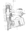
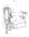
Hereinafter, an embodiment of the present invention will be described in detail with reference to the drawings. First of all, a first example of a fastening tool will be described with reference to Figs. 1 to 8. A fastening tool 10 includes: a main body 11; an impact-driving part 12; and a magazine 13. The main body 11 is a casing which houses a part, a component, or a mechanism for generating an impact force for driving a nail (not illustrated). The main body 11 includes: a housing 14; a handle 15; a head cover 16; and a guide part 17. The housing 14 is configured to be hollow. The housing 14, the guide part 17, and the head cover 16 are fixed to one another in a state that the guide part 17 is arranged between an opening portion of the housing 14 on one end side thereof and the head cover 16. A cylindrical cylinder 18 is provided so as to extend inside the housing 14, the guide part 17, and the head cover 16. The cylinder 18 is provided with taking a centerline A as its center, and the cylinder 18 is fixed so as to be immovable in a direction along the centerline A. The cylinder 18 is made of a metal material.
On the other hand, the handle 15 is a part which a worker using the fastening tool 10 holds with his/her hand, and the handle 15 is configured so as to be hollow. A pressure accumulating chamber 15a is provided inside the handle 15. The handle 15 is formed in a bar shape, and one end of the handle 15 in a longitudinal direction thereof is fixed to an outer wall of the housing 14 and the guide part 17. A plug 15b is provided at an end portion of the handle 15 opposite to the end portion thereof fixed to the housing 14. The plug 15b is an air tube which communicates with the pressure accumulating chamber 15a, and an air hose (not illustrated) can be attached to and detached from the plug 15b.
The guide part 17 includes an outer cylinder 17a and an inner cylinder 17b, and the outer cylinder 17a and the inner cylinder 17b are coaxially arranged with each other with taking the centerline A as the center. The outer cylinder 17a is provided so as to surround an outside of the inner cylinder 17b in a radial direction with taking the centerline A as the center. The outer cylinder 17a and the inner cylinder 17b are connected to each other at a part thereof in a circumferential direction by a connecting part 17c, and a first passage 17d is provided between the outer cylinder 17a and the inner cylinder 17b. The head cover 16 includes: a cylindrical part 16a; and an end part 16b formed by closing one end of the cylindrical part 16a. An opening end of the outer cylinder 17a comes in contact with an opening end of the cylindrical part 16a to be fixed thereto. The pressure accumulating chamber 15a communicates with an inner part 16c of the head cover 16 via the first passage 17d.
A mount part 19 is provided at the inner part 16c of the head cover 16, more specifically, the end part 16b thereof with taking the centerline A as the center. A stopper 20 is attached to the mount part 19, and the stopper 20 is made of a rubber-like elastic body. Further, an annular cylinder 16d is provided at the end part 16b of the head cover 16 so as to surround the mount part 19. Still further, a head valve 21 is provided between the mount part 19 and the cylinder 16d. The head valve 21 is operable in the direction along the centerline A in a state that an outer peripheral surface of the head valve 21 comes in contact with the cylinder 16d and an inner peripheral surface of the head valve 21 comes in contact with the mount part 19. A head valve chamber 22 is provided between the head valve 21 and the end part 16b. Further, a spring 23 is provided between the head valve 21 and the mount part 19, and the spring 23 has a force in a direction of pushing the head valve 21 so as to be separated from the stopper 20 in the direction along the centerline A. A length of the head valve 21 in the direction along the centerline A is shorter than a length of the cylinder 18. Further, the head valve 21 is made of a resin material, and is lighter than the cylinder 18.
The magazine 13 is a container which holds a lot of nails coupled to one another. The magazine 13 has a mechanism (not illustrated) which sequentially transfers the held nails to an impact-driving part 12. The impact-driving part 12 is a mechanism which holds the nail supplied from the magazine 13 at a position at which the nail is to be impacted by the driver blade and linearly guides a direction in which the nail to be impacted is driven. The impact-driving part 12 includes an undercover 12a and a guide cylinder 12b. The undercover 12a is fixed to an opening end of the housing 14 opposite to the opening end thereof attached with the guide part 17. The undercover 12a includes an axial hole 22a which is coaxial with the centerline A. An inner diameter of the axial hole 22a is smaller than an inner diameter of the cylinder 18. The guide cylinder 12b is provided coaxially with the cylinder 18 and the axial hole 22a. Further, a push rod 24 is attached at a tip of the guide cylinder 12b. The push rod 24 comes into contact with an object into which the nail is to be driven.
A damper 25 is provided so as to extend from the inside of the cylinder 18 to the inside of the undercover 12a. The damper 25 is integrally formed of a rubber-like elastic body, and the damper 25 has a cylindrical shape. An inner diameter of an axial hole 25a of the damper 25 is larger than an inner diameter of the axial hole 22a. The damper 25 is arranged coaxially with the cylinder 18. And, a piston 26 is provided inside the cylinder 18. An O-ring 26a is attached to an outer peripheral surface of the piston 26 so that the piston 26 is reciprocable in the direction along the centerline A. A driver blade 26b is provided at an end portion of the piston 26 on the damper 25 side. The driver blade 26b is formed in a bar shape, and the driver blade 26b is provided so as to extend inside the cylinder 18 and inside the axial hole 25a. The driver blade 26b has such a length that a tip thereof reaches the axial hole 22a of the undercover 12a in a state that the piston 26 is in contact with the stopper 20 to be stopped.
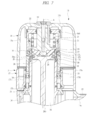
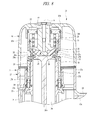
Also, as illustrated in Figs. 7 and 8, a cylindrical member 27 is interposed between the stopper 20 and an end portion of the cylinder 18 on the stopper 20 side. The cylindrical member 27 has a second passage 27a which radially penetrates through therein with taking the centerline A as the center. Further, a first air chamber 28 is provided between the stopper 20 and the piston 26 so that the first air chamber 28 is connected to the second passage 27a. Air pressure in the first air chamber 28 is converted into an operating force for operating the piston 26. The impact force is applied to the driver blade 26b by the operation of the piston 26. That is, the first air chamber 28 is a mechanism for applying the impact force to the driver blade 26b via the piston 26. Still further, a notch 27b is provided on an outer peripheral surface of the cylindrical member 27 in the direction along the centerline A. A plurality of the notches 27b are arranged at a predetermined interval along a circumstantial direction. A main valve 29 is provided so as to surround an outside of the cylinder 18. The main valve 29 is formed in a cylindrical shape with taking the centerline A as the center, and the main valve 29 is operable in the direction along the centerline A. An operation range of the main valve 29 in the direction along the centerline A overlaps with an arrangement region of the cylinder 18 in the direction along the centerline A. Further, an arrangement position of the main valve 29 in the direction along the centerline A is different from an arrangement position of the head valve 21 in the direction along the centerline A. A pressure receiving surface 29a is provided at an end portion of the main valve 29 on the head valve 21 side. The pressure receiving surface 29a is provided at an upper end of the head valve 21 in Figs. 7 and 8. The pressure receiving surface 29a is formed in an annular shape with taking the centerline A as the center, and the pressure receiving surface 29a is inclined with respect to the centerline A. The main valve 29 is pressed in a direction which separates from the mount part 19 when air pressure is applied to the pressure receiving surface 29a.
Further, an annular valve seat (valve seat) 30 is attached to an outer peripheral surface of the cylinder 18. And, a third passage 31 is formed between the main valve 29 and the valve seat 30. Still further, a fourth passage 32 is provided between the main valve 29 and the cylinder 18 so that the fourth passage 32 communicates with an outside of the main body 11, that is, atmosphere.
On the other hand, a holder 33 is provided between the cylinder 18 and the inner cylinder 17b. The holder 33 is formed in an annular shape with taking the centerline A as the center, and a spring 34 is interposed between the holder 33 and the main valve 29. The main valve 29 is pressed toward the head valve 21 by a force of the spring 34. A fifth passage 35 is formed between an end portion of the main valve 29 and an end portion of the head valve 21. The head valve 21 is a mechanism for switching opening/closing of the fifth passage 35.
A second air chamber 36 is provided between the piston 26 and the damper 25 inside the cylinder 18. A volume of the second air chamber 36 is changed by the operation of the piston 26 in the direction along the centerline A. The O-ring 26a attached to the piston 26 comes in contact with an inner peripheral surface of the cylinder 18 so as to form a seal surface. That is, the first air chamber 28 and the second air chamber 36 are partitioned from each other by the O-ring 26a with air tight. Further, an annular third air chamber 37 with taking the centerline A as the center is provided between the outer peripheral surface of the cylinder 18 and the inner peripheral surface of the housing 14. And, in the cylinder 18, a sixth passage 18a which penetrates through therein is radially provided. The sixth passage 18a connects between the second air chamber 36 and the third air chamber 37. Also, a check valve 38 for opening/closing the sixth passage 18a is provided inside the housing 14. The check valve 38 is configured so as to be opened in a direction in which air flows from the second air chamber 36 to the third air chamber 37 and be closed in a direction in which air flows from the third air chamber 37 to the second air chamber 36. Further, in the cylinder 18, a seventh passage 39 which always connects between the second air chamber 36 and the third air chamber 37 is provided. The seventh passage 39 is arranged between the sixth passage 18a and the damper 25 in the direction along the centerline A.
Still further, as illustrated in Fig. 2, the main body 11 includes an eighth passage 40 for connecting between the third air chamber 37 and the head valve chamber 22. The eighth passage 40 is provided so as to extend in the housing 14, the guide part 17, and the head cover 16. Still further, a trigger valve 41 is provided in the handle 15. The trigger valve 41 includes a spool 41a. In the main body 11, a trigger 42 operated by the worker is provided. The spool 41a is operated by operation of the trigger 42.
Next, an operation and a function of the fastening tool 10 of the first example will be described. Note that, in Figs. 1 to 8, the operation and the function of the fastening tool 10 will be described with assumption that the centerline A is arranged in up and down directions (a vertical direction).
As illustrated in Fig. 1, in the fastening tool 10, the head valve 21 is pushed toward the end part 16b to be stopped by the force of the spring 23 when the push rod 24 is not in contact with the object or when the trigger 42 is not operated even if the push rod 24 is in contact with the object. Such a state that the compressed air is supplied to the fastening tool 10 and that the push rod 24 and the trigger 42 are not operated is defined as an initial state. Further, as illustrated in Fig. 7, the main valve 29 is pushed by the force of the spring 34 to come in contact with the head valve 21 so that the fifth passage 35 has been closed. Note that, when the trigger 42 is not operated, it is set that the air pressure in the pressure accumulating chamber 15a is not applied to the pressure receiving surface 29a of the main valve 29 by the operation of the trigger valve 41. Further, the third passage 31 formed between the main valve 29 and the valve seat 30 has been opened. Therefore, the first air chamber 28 communicates with the atmosphere via the second passage 27a, the notches 27b, the third passage 31, and the fourth passage 32. Further, the piston 26 comes in contact with the stopper 20 so as to stop at the top dead point.
Next, when the push rod 24 is in contact with the object, and besides, when the trigger 42 is operated, the air pressure in the pressure accumulating chamber 15a is applied to the pressure receiving surface 29a of the main valve 29 by the operation of the trigger valve 41. Accordingly, as illustrated in Fig. 8, the main valve 29 is operated (descended) in a direction which is against the force of the spring 34 and approaches the holder 33. When the main valve 29 is descended, the fifth passage 35 is opened, and besides, the third passage 31 is closed. And, the air in the pressure accumulating chamber 15a flows into the first air chamber 28 via the fifth passage 35 so that the air pressure in the first air chamber 28 increases. Accordingly, the piston 26 is operated (descended) toward the damper 25, and besides, the air in the second air chamber 36 partially flows into the third air chamber 37 via the seventh passage 39. Here, when the piston 26 is positioned between the sixth passage 18a and the stopper 20 in the direction along the centerline A, the check valve 38 is closed by the air pressure in the third air chamber 37. Further, the air in the third air chamber 37 partially flows into the head valve chamber 22. However, when the force applied from the spring 23 to the head valve 21 is stronger than the force applied to the head valve 21 by the air pressure in the head valve chamber 22, the head valve 21 is in contact with the end part 16b to be stopped.
Thereafter, when the nail is impacted by the driver blade 26b, and besides, the piston 26 is moved between the sixth passage 18a and the damper 25, the check valve 38 is opened by the air pressure in the first air chamber 28. Accordingly, the air in the first air chamber 28 partially flows into the third air chamber 37 via the sixth passage 18a. Further, the piston 26 approaches the damper 25, the piston 26 comes in contact with the damper 25 as illustrated in Fig. 4, and the piston 26 stops at the bottom dead point.
After the nail impact (driving operation) by the driver blade 26b is performed, if the force applied to the head valve 21 by the air pressure in the head valve chamber 22 exceeds the force applied from the spring 23 to the head valve 21, the head valve 21 is operated (descended) in the direction which is against the force of the spring 23 as illustrated in Fig. 5 and which approaches the main valve 29 so that the head valve 21 comes in contact with the main valve 29 to close the fifth passage 35.
Subsequently, as illustrated in Fig. 6, when the operation of the trigger 42 is cancelled, the air pressure applied from the pressure accumulating chamber 15a to the pressure receiving surface 29a of the main valve 29 decreases. Accordingly, the main valve 29 is operated (ascended) in a direction which approaches the cylinder 16d by the force of the spring 34. That is, the main valve 29 is operated in a direction reverse to the direction in which the piston 26 is operated by the air pressure in the first air chamber 28. Further, the head valve 21 is operated in contact with the main valve 29, and the head valve 21 comes in contact with the end part 16b so that the main valve 29 and the head valve 21 stop. Accordingly, the third passage 31 is opened, and the first air chamber 28 communicates with the atmosphere via the second passage 27a, the notches 27b, and the fourth passage 32, so that the air pressure in the first air chamber 28 decreases. Further, the air in the third air chamber 37 partially flows into the second air chamber 36, so that the piston 26 is operated (ascended) in a direction which approaches the stopper 20. And, the piston 26 comes in contact with the stopper 20 to be stopped at the top dead point. That is, the fastening tool 10 returns to the initial state illustrated in Fig. 1. As described above, the third air chamber 37 plays a role of a returning air chamber which accumulates the compressed air for returning the piston 26 to the initial position after the nail impact-driving operation is completed.
As described above, in the fastening tool 10, when the nail is impacted by the driver blade 26b, and besides, when the piston 26 moves between the sixth passage 18a and the damper 25, the head valve 21 is operated to close the fifth passage 35. Therefore, even if the trigger 42 is operated, it is prevented that the compressed air in the pressure accumulating chamber 15a flows into the first air chamber 28. That is, in the fastening tool 10, the consumption amount of the compressed air can be reduced. Further, the length of the head valve 21 in the direction along the centerline A is shorter than the length of the cylinder 18, so that an operational resistance (frictional resistance) of a contracting portion of the head valve 21 can be reduced. Therefore, in the prevention of the flowing of the compressed air in the pressure accumulating chamber 15a into the first air chamber 28, the force required for the operation of the head valve 21 can be reduced. Therefore, the operation response performance of the head valve 21 is improved.
Further, since the head valve 21 is lighter than the cylinder 18, the force required for the operation of the head valve 21 can be further reduced. Still further, by using the fastening tool 10 in the state that the centerline A extends along the up and down directions (the vertical direction), the head valve 21 is descended along a direction of action of the gravity to close the fifth passage 35. Therefore, the force required for the operation of the head valve 21 can be further reduced. Further, the head valve 21 is operated by using the air pressure in the third air chamber 37. Therefore, it is not required to provide a dedicated actuator for operating the head valve 21.
Further, the operation range of the main valve 29 in the direction along the centerline A overlaps with the arrangement region of the cylinder 18. Therefore, it is not required to provide a dedicated arrangement space for the main valve 29 in the direction along the centerline A, so that increase in a size of the fastening tool 10 can be suppressed.
Note that a spring constant of the spring 23 can be a factor for determining the timing of closing the fifth passage 35 by the operation of the head valve 21. For example, by a small spring constant, the timing of closing the fifth passage 35 by the operation of the head valve 21 can be advanced.
Here, in description of a correspondence relation between the configuration of the first example in the fastening tool 10 of the present invention and the configuration of the present invention, the fifth passage 35 corresponds to a passage of the present invention, the main valve 29 corresponds to a closing member of the present invention, and the head valve 21 corresponds to a valving element of the present invention. Further, a position (a top dead point) at which the piston 26 is in contact with the stopper 20 to be stopped corresponds to an initial position of the present invention.
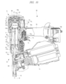
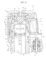
Next, a second example of the fastening tool of the present invention will be described with reference to Figs. 9 to 12. A fastening tool 50 includes: a main body 51; an impact-driving part 52; and a magazine 53. The main body 51 is a mechanism for generating an impact force for driving the nail, and the main body 51 includes: a handle 54; a head cover 55; and a housing 56. The handle 54 is a part which a worker using the fastening tool 50 holds with his/her hand, and the handle 54 is configured to be hollow. Inside the handle 54, a pressure accumulating chamber 54a is provided. The handle 54 is formed in a bar shape, and an end of the handle 54 in a longitudinal direction thereof is fixed to an outer wall of the housing 56. A plug 54b is provided at an end portion of the handle 54 opposite to an end portion thereof fixed to the housing 56. The plug 54b is an air tube communicating with the pressure accumulating chamber 54a, and an air hose can be attached to and detached from the plug 54b.
The housing 56 has a cylindrical shape, and one opening end of the housing 56 is closed by the head cover 55. The head cover 55 includes: a cylindrical part 55a; and an end part 55b formed by closing one opening end of the cylindrical part 55a. A stopper 57 is attached to the end part 55b. The stopper 57 is made of a rubber-like elastic body. Also, a cylinder 58 is provided so as to extend inside the housing 56 and inside the head cover 55. The cylinder 58 has a cylindrical shape, and the cylinder 58 is fixed so as to be immovable with respect to the housing 56 and the head cover 55. The cylinder 58 is made of a metal material.
The magazine 53 is a container which holds a lot of nails coupled to one another. The magazine 53 has a mechanism (not illustrated) which sequentially transfers the held nails to the impact-driving part 52. The impact-driving part 52 is a mechanism which holds the nail supplied from the magazine 53 at a position at which the nail is impacted by the driver blade, and besides, which linearly guides a direction in which the nail to be impacted is driven. The impact-driving part 52 includes an undercover 59 and a guide cylinder 60. The undercover 59 is fixed to an opening end of the housing 56 opposite to the opening end thereof attached with the head cover 55. The undercover 59 includes an axial hole 59a which is coaxial with a centerline B. An inner diameter of the axial hole 59a is smaller than an inner diameter of the cylinder 58. The guide cylinder 60 is coaxially provided with the cylinder 58 and the axial hole 59a. Further, a push rod 61 is attached at a tip of the guide cylinder 60. The push rod 61 comes in contact with an object into which the nail is to be driven.
A damper 62 is provided so as to extend inside the cylinder 58 and inside the undercover 59. The damper 62 is integrally formed of a rubber-like elastic body, the damper 62 is formed in a cylindrical shape, and the damper 62 includes an axial hole 62a. The minimum inner diameter of the axial hole 62a is equal to or larger than the inner diameter of the axial hole 59a. The damper 62 is arranged coaxially with the cylinder 58. And, inside the cylinder 58, a piston 63 is provided. An O-ring 63a is attached to an outer peripheral surface of the piston 63, and the piston 63 is movable in a direction along the centerline B of the cylinder 58. A driver blade 63b is provided at an end portion of the piston 63 on the damper 62 side. When the piston 63 is in contact with the stopper 57, the driver blade 63b is provided so as to extend inside the cylinder 58 and inside the axial hole 62a. The driver blade 63b has such a length that a tip thereof reaches the axial hole 59a in a state that the piston 63 is in contact with the stopper 57.
On the other hand, a head valve holding part 64 is provided at the end part 55b. The head valve holding part 64 is annularly provided with taking the centerline B as the center. Inside the head valve holding part 64, a head valve 65 operable in the direction along the centerline B is inserted. The head valve 65 is formed in a cylindrical shape so as to surround the stopper 57 with taking the centerline B as the center. Inside the head valve holding part 64, a head valve chamber 66 is provided between the head valve 65 and the end part 55b. The head valve 65 is pushed in a direction which approaches the cylinder 58 by air pressure in the head valve chamber 66. Further, as illustrated in Fig. 12, in the head valve 65, a pressure receiving surface 65a is formed at an end portion thereof opposite to the head valve chamber 66 in the direction along the centerline B.
Still further, inside the head cover 55, a cylindrical-shaped guide member 67 is provided. The guide member 67 is provided coaxially with the cylinder 58, and the guide member 67 is fixed so as to be immovable in the direction along the centerline B. An inward flange 67a is provided at an inner peripheral surface of the guide member 67, and a first passage 68 which penetrates through the inward flange 67a in the direction along the centerline B is provided in the inward flange 67a. The first passage 68 is always connected to the pressure accumulating chamber 54a. The air pressure in the pressure accumulating chamber 54a is applied to the pressure receiving surface 65a of the head valve 65 via the first passage 68 to generate a force acting in a direction in which the head valve 65 approaches the end part 55b. Further, when the head valve 65 moves in the direction along the centerline B, an outer peripheral surface thereof comes in contact with an inner peripheral surface of the guide member 67 and an inner peripheral surface of the head valve holding part 64 so as to be guided.
Further, an annular collar part 57a is provided on an outer peripheral surface of the stopper 57, and a second passage 69 is formed between the collar part 57a and the head valve 65. Further, a first air chamber 70 is formed between the stopper 57 and the piston 63. Still further, at the head cover 55, a third passage 71 communicating with the atmosphere outside the main body 51 is provided. Still further, a fourth passage 82 is formed between the head valve 65 and the cylinder 58. The fourth passage 82 is a path for connecting between the first passage 68 and the first air chamber 70. The opening/closing of the fourth passage 82 is switched by movement of the head valve 65 in the direction along the centerline B.
On the other hand, a trigger valve 72 is provided in the handle 54. The trigger valve 72 includes a spool 72a. In the main body 51, a trigger 73 operated by the worker is provided. The spool 72a is operated by operation of the trigger 73. The head valve chamber 66 is connected to the trigger valve 72 via the fifth passage 74, and the fifth passage 74 is connected to either one of the pressure accumulating chamber 54a and the atmosphere by operation of the spool 72a.
A second air chamber 75 is provided between the piston 63 and the damper 62 inside the cylinder 58. The O-ring 63a attached to the outer peripheral surface of the piston 63 comes in contact with the inner peripheral surface of the cylinder 58 to form a seal surface. The first air chamber 70 and the second air chamber 75 are partitioned from each other by the seal surface with air tight. A volume of the second air chamber 75 is changed by operation of the piston 63 in the direction along the centerline B. Further, an annular third air chamber 76 with taking the centerline B as the center is provided between the outer peripheral surface of the cylinder 58 and the inner peripheral surface of the housing 56. In the present embodiment, the third air chamber 76 also serves as a returning air chamber which accumulates compressed air for returning the piston 63 to an initial position after the nail impact-driving operation is completed. It is not required that the third air chamber 76 and the returning air chamber are the same with each other. However, by such a configuration, wasteful usage of the compressed air can be prevented, and besides, the number of chambers to be formed inside the main body 51 can be reduced, and therefore, the main body 51 can be downsized. And, in the cylinder 58, a sixth passage 77 which penetrates through the cylinder 58 in a radial direction is formed. The sixth passage 77 is a passage for connecting between the second air chamber 75 and the third air chamber 76.
Further, a check valve 78 for opening/closing the sixth passage 77 is provided at an outer periphery of the cylinder 58. The check valve 78 has a configuration so as to be opened in a direction in which air flows from the second air chamber 75 to the third air chamber 76 and be closed in a direction in which air flows from the third air chamber 76 to the second air chamber 75. Further, in the cylinder 58, a seventh passage 79 which always connects between the second air chamber 75 and the third air chamber 76 is provided. The seventh passage 79 is provided between the sixth passage 77 and the undercover 59 in the direction along the centerline B.
Further, a cylindrical-shaped sleeve 80 is provided outside the cylinder 58. The sleeve 80 is provided between the sixth passage 77 and the head valve 65 in the direction along the centerline B. That is, a position of the sleeve 80 in the direction along the centerline B is different from a position of the head valve 65 in the direction along the centerline B. The sleeve 80 is pushed toward the head valve 65 by the air pressure in the third air chamber 76. The sleeve 80 is made of a metal material. The sleeve 80 has a length in the direction along the centerline B shorter than a length of the cylinder 58, and is lighter than the cylinder 58. Further, the sleeve 80 is arranged coaxially with the cylinder 58, and the sleeve 80 is movable along the centerline B in a contact state with the outer peripheral surface of the cylinder 58. An operation range of the sleeve 80 in the direction along the centerline B overlaps with an arrangement region of the cylinder 58. Further, a stopper 81 is fixed at an inner peripheral surface of the housing 56. The stopper 81 is formed in an annular shape with taking the centerline B as the center. The stopper 81 is arranged between the sleeve 80 and the sixth passage 77 in the direction along the centerline B. Further, a configuration is adopted, in which air pressure in the pressure accumulating chamber 54a is applied to an end portion of the sleeve 80 on the head valve 65 side via the first passage 68. Therefore, the sleeve 80 is pushed toward the stopper 81 by the air pressure applied via the first passage 68.
Next, an operation and a function of the fastening tool 50 according to the second example will be described. Note that, in Figs. 9 to 12, the operation and the function of the fastening tool 50 will be described with assumption that the centerline B is arranged along up and down directions.
In the fastening tool 50, the pressure accumulating chamber 54a is connected to the head valve chamber 66 via the fifth passage 74 when the push rod 61 is not in contact with an object or when the trigger 73 is not operated as illustrated in Fig. 9 even if the push rod 61 is in contact with the object. The air pressure in the pressure accumulating chamber 54a is applied to the pressure receiving surface 65a of the head valve 65 via the first passage 68. However, a force of pushing the head valve 65 by the air pressure in the head valve chamber 66 is stronger than a force of pushing the head valve 65 by the air pressure in the pressure accumulating chamber 54a via the first passage 68.
Therefore, the head valve 65 is pushed in a direction which approaches the sleeve 80 so that the head valve 65 and the sleeve 80 are in contact with each other, which results in closing the fourth passage 82. Further, the sleeve 80 pushed by the head valve 65 comes in contact with the stopper 81 to be stopped. Still further, the second passage 69 is opened so that the first air chamber 70 communicates with the atmosphere via the second passage 69. Still further, the piston 63 comes in contact with the stopper 57 to be stopped at a top dead point.
Subsequently, when the push rod 61 is in contact with the object, and besides, when the trigger 73 is operated, the head valve chamber 66 communicates with the atmosphere via the fifth passage 74. Accordingly, as illustrated in Figs. 10 and 12, the head valve 65 is operated (ascended) in a direction which separates from the sleeve 80 by the air applied to the pressure receiving surface 65a. By the ascent of the head valve 65, the fourth passage 82 is opened, and besides, the second passage 69 is closed. Note that the air pressure in the pressure accumulating chamber 54a is applied to the end portion of the sleeve 80 on the head valve 65 side, and therefore, the sleeve 80 is maintained in the stopping state in contact with the stopper 81.
Further, when the fourth passage 82 is opened, the compressed air in the pressure accumulating chamber 54a flows into the first air chamber 70 via the first passage 68 and the fourth passage 82. Accordingly, the pressure in the first air chamber 70 increases so that the piston 63 is operated (descended) in the direction which approaches the damper 62. By the descent of the piston 63, the air in the second air chamber 75 partially flows into the third air chamber 76 via the seventh passage 79. Further, the check valve 78 is closed by the air pressure in the third air chamber 76.
During the descent of the piston 63, the pressure of air passing through the fourth passage 82 is applied to the end portion of the sleeve 80 on the head valve 65 side. On the other hand, the air pressure in the third air chamber 76 is applied to an end surface of the sleeve 80. Here, when the piston 63 is positioned between the sixth passage 77 and the stopper 57 in the direction along the centerline B, the air pressure in the pressure accumulating chamber 54a is higher than the air pressure in the third air chamber 76, and therefore, the sleeve 80 is maintained in the contacting state with the stopper 81.
Then, the driver blade 63b is descended together with the piston 63, and the nail is impacted by the driver blade 63b, and then, the piston 63 is moved between the sixth passage 77 and the damper 62 as illustrated in Fig. 11. Accordingly, the air pressure in the first air chamber 70 is higher than the air pressure in the third air chamber 76, and therefore, the check valve 78 is opened so that the air in the first air chamber 70 partially flows into the third air chamber 76 via the sixth air passage 77. The sleeve 80 is operated (ascended) by the air pressure in the third air chamber 76 in the direction which approaches the head valve 65. That is, the sleeve 80 is operated in a direction reverse to the direction in which the piston 63 is operated by the air pressure in the first air chamber 70.
By the ascent of the sleeve 80, the sleeve 80 comes in contact with the head valve 65 to close the fourth passage 82, so that the pressure accumulating chamber 54a and the first air chamber 70 are blocked from each other. As a result, even if the trigger 73 is operated, the compressed air in the pressure accumulating chamber 54a is not supplied to the first air chamber 70.
Subsequently, by cancel of the operation of the trigger 73, the pressure accumulating chamber 54a and the head valve chamber 66 are connected to each other via the fifth passage 74 to increase the air pressure in the head valve chamber 66, so that the head valve 65 is operated (descended) in the direction which approaches the cylinder 58. By the descent of the head valve 65, the second passage 69 is opened to connect between the first air chamber 70 and the atmosphere, so that the air pressure in the first air chamber 70 decreases. Further, the sleeve 80 is descended together with the head valve 65, and is in contact with the stopper 81 to be stopped. That is, the fourth passage 82 is maintained in a closing state by the head valve 65.
As described above, by the decrease in the air pressure in the first air chamber 70, the piston 63 is operated (ascended) by the air pressure in the second air chamber 75 in the direction which approaches the stopper 57. And, the piston 63 comes in contact with the stopper 57 to be stopped at the top dead point, and returns to the initial state illustrated in Fig. 9.
As described above, in the second example, after the nail is impacted by the driver blade 63b, when the piston 63 moves between the sixth passage 77 and the damper 62, the fourth passage 82 is closed even if the trigger 73 is operated, and therefore, the compressed air in the pressure accumulating chamber 54a is not supplied to the first air chamber 70. Therefore, the fastening tool 50 can reduce the consumption amount of the compressed air.
Further, the sleeve 80 has the length in the direction along the centerline B longer than the length of the cylinder 58, so that an operation resistance (frictional resistance) of a contacting portion of the sleeve 80 can be reduced. Therefore, in the prevention of the flowing of the compressed air in the pressure accumulating chamber 54a into the first air chamber 70, a force required for the operation of the sleeve 80 can be reduced. Therefore, an operation response performance of the sleeve 80 is improved.
Further, since the sleeve 80 is lighter than the cylinder 58, the force required for the operation of the sleeve 80 can be further reduced. Further, since the sleeve 80 is operated along the outer peripheral surface of the cylinder 58, a coaxial degree with the head valve 65 is maintained, so that the fourth passage 82 can be securely closed. Further, since the head valve 65 is operated by using the air pressure in the third air chamber 76, it is not required to provide a dedicated actuator for operating the head valve 65. Further, the operation range of the sleeve 80 in the direction along the centerline B overlaps with the arrangement region of the cylinder 58. Therefore, increase in a size of the fastening tool 50 can be suppressed.
Here, in description of a correspondence relation between the configuration of the second example of the fastening tool of the present invention and the configuration of the present invention, the fourth passage 82 corresponds to the passage of the present invention, the sleeve 80 corresponds to the closing member of the present invention, and the head valve 65 corresponds to the valving element of the present invention. The top dead point at which the piston 63 comes in contact with the stopper 57 to be stopped corresponds to the initial position of the present invention.
It is needless to say that the present invention is not limited to the above-described embodiment and various modifications and alterations can be made within the scope of the present invention. For example, in the above-described embodiment, the nail may be a tacker (staple) bent in a U shape in addition to a straight nail. Further, in each drawing, the centerline A or B is arranged along the vertical direction. However, in the fastening tool of the present embodiment, the nail can be impacted by the driver blade even in a state that the centerline A or B is arranged along a horizontal direction or that the centerline A or B is arranged along a direction between the vertical direction and the horizontal direction. In the present invention, each passage is a pass through which air passes, and it includes a space formed between components, a hole provided in a component, a notch provided in a component, a trench provided in a component, a port provided in a component, and others.
Further, of course, the fastening tool of the present invention can be applied to a screw fastening tool for driving a screw with using compressed air of a main valve. That is, an object to be driven by a fastening tool includes a nail, a screw, and others.
The present invention can be used for a fastening tool having a structure that a piston is operated with using compressed air so that a nail is impacted by an operation force of the piston.
Claims (6)
- A fastening tool comprising:
a main body;
a cylinder provided inside the main body;
a piston provided inside the cylinder so as to be reciprocable in a direction along a centerline of the cylinder;
a driver blade fixed to the piston and operated together with the piston to impact an object to be driven;
a first air chamber to which compressed air for applying an operating force acting in a direction along the centerline to the piston is supplied;
a second air chamber whose volume is changed by operation of the piston in a direction along the centerline;
a pressure accumulating chamber which accumulates compressed air to be supplied to the first air chamber;
a passage which connects between the first air chamber and the pressure accumulating chamber; and
a valving element which moves in the direction along the centerline to switch opening/closing of the passage,
characterized in that
the fastening tool includes:
a third air chamber into which air flows after the passage is opened by movement of the valving element; and
a closing member which is operated by the air pressure in the third air chamber to close the passage after the passage is opened, and
a length of the closing member in the direction along the centerline is shorter than a length of the cylinder in the direction along the centerline. - The fastening tool according to claim 1,
characterized in that
the closing member is provided at a position different from the valving element in the direction along the centerline, and is operable in the direction along the centerline. - The fastening tool according to claim 1,
characterized in that
the passage is formed between the closing member and the valving element,
the passage is closed by the valving element and the closing member being in contact with each other in a state that the piston stops at an initial position , and the passage is opened by the valving element being separated from the closing member when the piston and the driver blade moves to the object to be driven, and,
after the valving element is operated so that the passage is opened, the closing member is operated by air pressure in the third air chamber in the direction along the centerline so that the passage is closed. - The fastening tool according to claim 1,
characterized in that
an operation range of the closing member in the direction along the centerline overlaps with an arrangement region of the cylinder in the direction along the centerline,
the closing member is operated in the same direction as a direction in which the piston is operated by air pressure in the first air chamber so that the passage is opened, and
the valving element is provided at a position different from the closing member in the direction along the centerline, and provided coaxially with the closing member, and the closing member is operated in the same direction as a direction in which the piston is operated by the air pressure in the first air chamber so that the passage is closed. - The fastening tool according to claim 1,
characterized in that
the valving element is provided at a position different from the cylinder in the direction along the centerline, and provided coaxially with the cylinder,
an operation range of the closing member in the direction along the centerline overlaps with an arrangement region of the cylinder in the direction along the centerline,
the closing member is operated in a direction reverse to a direction in which the piston is operated by the air pressure in the first air chamber so that the passage is closed, and
the closing member is operated in the same direction as a direction in which the piston is operated by the air pressure in the first air chamber so that the passage is opened. - The fastening tool according to claim 1,
characterized in that
the third air chamber also serves as a returning air chamber which accumulates compressed air for returning the piston to the initial position after completion of an impact-driving operation.
Applications Claiming Priority (2)
| Application Number | Priority Date | Filing Date | Title |
|---|---|---|---|
| JP2012-081816 | 2012-03-30 | ||
| JP2012081816A JP5842713B2 (en) | 2012-03-30 | 2012-03-30 | Driving machine |
Publications (1)
| Publication Number | Publication Date |
|---|---|
| WO2013145685A1 true WO2013145685A1 (en) | 2013-10-03 |
Family
ID=48096121
Family Applications (1)
| Application Number | Title | Priority Date | Filing Date |
|---|---|---|---|
| PCT/JP2013/001996 Ceased WO2013145685A1 (en) | 2012-03-30 | 2013-03-25 | Fastening tool driven by compressed air |
Country Status (2)
| Country | Link |
|---|---|
| JP (1) | JP5842713B2 (en) |
| WO (1) | WO2013145685A1 (en) |
Cited By (2)
| Publication number | Priority date | Publication date | Assignee | Title |
|---|---|---|---|---|
| EP3162510A4 (en) * | 2014-06-30 | 2018-03-14 | Hitachi Koki Co., Ltd. | Driving machine |
| WO2021158125A1 (en) * | 2020-02-03 | 2021-08-12 | Globalforce Ip Limited | Improvements in, or relating to, exhaust valves for pressurised fluid operated devices |
Families Citing this family (2)
| Publication number | Priority date | Publication date | Assignee | Title |
|---|---|---|---|---|
| CN103885458A (en) * | 2014-01-17 | 2014-06-25 | 中国科学院上海技术物理研究所 | Fast reflection mirror scanning tracking system for aerospace imaging field and method thereof |
| KR102668005B1 (en) * | 2017-12-11 | 2024-05-23 | 씨엠엘 인터내셔널 에스. 피. 에이. | Hydraulically operated rotary pipe bending machine |
Citations (2)
| Publication number | Priority date | Publication date | Assignee | Title |
|---|---|---|---|---|
| EP0205633A1 (en) * | 1985-06-21 | 1986-12-30 | Joh. Friedrich Behrens AG | Valve assembly |
| JP2010064225A (en) | 2008-09-12 | 2010-03-25 | Hitachi Koki Co Ltd | Driving machine |
-
2012
- 2012-03-30 JP JP2012081816A patent/JP5842713B2/en not_active Expired - Fee Related
-
2013
- 2013-03-25 WO PCT/JP2013/001996 patent/WO2013145685A1/en not_active Ceased
Patent Citations (2)
| Publication number | Priority date | Publication date | Assignee | Title |
|---|---|---|---|---|
| EP0205633A1 (en) * | 1985-06-21 | 1986-12-30 | Joh. Friedrich Behrens AG | Valve assembly |
| JP2010064225A (en) | 2008-09-12 | 2010-03-25 | Hitachi Koki Co Ltd | Driving machine |
Cited By (4)
| Publication number | Priority date | Publication date | Assignee | Title |
|---|---|---|---|---|
| EP3162510A4 (en) * | 2014-06-30 | 2018-03-14 | Hitachi Koki Co., Ltd. | Driving machine |
| US10744629B2 (en) | 2014-06-30 | 2020-08-18 | Koki Holdings Co., Ltd. | Fastener driving tool |
| WO2021158125A1 (en) * | 2020-02-03 | 2021-08-12 | Globalforce Ip Limited | Improvements in, or relating to, exhaust valves for pressurised fluid operated devices |
| US12365070B2 (en) | 2020-02-03 | 2025-07-22 | Globalforce Ip Limited | Exhaust valves for pressurised fluid operated devices |
Also Published As
| Publication number | Publication date |
|---|---|
| JP2013208693A (en) | 2013-10-10 |
| JP5842713B2 (en) | 2016-01-13 |
Similar Documents
| Publication | Publication Date | Title |
|---|---|---|
| US11185967B2 (en) | Driving tool | |
| EP2747945B1 (en) | Fastening tool | |
| EP3162510B1 (en) | Fastener driving tool | |
| US10016884B2 (en) | Pneumatic nail gun capable of striking nails in automatic mode | |
| JP6819045B2 (en) | Driving machine | |
| CN102528750B (en) | For adjusting the fastened tools of the driving degree of depth of securing member | |
| EP3036069B1 (en) | Pneumatic fastener driver | |
| WO2013145685A1 (en) | Fastening tool driven by compressed air | |
| TWI540028B (en) | Fastener driving tool | |
| CN103029102B (en) | Driver | |
| JP2014233770A (en) | Driving machine | |
| JP5589804B2 (en) | Driving machine | |
| CN111278606B (en) | Compressed air nail gun comprising a safety valve arrangement | |
| US6845896B2 (en) | Expulsion device actuated by a pressure medium | |
| JP7222304B2 (en) | pneumatic tools | |
| JPH0616660Y2 (en) | Recoil absorption mechanism in reciprocating nailer | |
| JP2015058486A (en) | Driving machine | |
| JPH0616670Y2 (en) | Safety device for nailer | |
| JPH0616659Y2 (en) | Recoil absorption mechanism in repetitive actuation impact tool | |
| JP2014147996A (en) | Driving machine | |
| JP2736840B2 (en) | Pneumatic fixture driving machine | |
| JPH0546856Y2 (en) | ||
| JP5741939B2 (en) | Driving machine | |
| JPH0544062Y2 (en) | ||
| JPH0544061Y2 (en) |
Legal Events
| Date | Code | Title | Description |
|---|---|---|---|
| 121 | Ep: the epo has been informed by wipo that ep was designated in this application |
Ref document number: 13716448 Country of ref document: EP Kind code of ref document: A1 |
|
| NENP | Non-entry into the national phase |
Ref country code: DE |
|
| 122 | Ep: pct application non-entry in european phase |
Ref document number: 13716448 Country of ref document: EP Kind code of ref document: A1 |