WO2013145417A1 - Sleep state management device, sleep state management method, and sleep state management program - Google Patents
Sleep state management device, sleep state management method, and sleep state management program Download PDFInfo
- Publication number
- WO2013145417A1 WO2013145417A1 PCT/JP2012/079287 JP2012079287W WO2013145417A1 WO 2013145417 A1 WO2013145417 A1 WO 2013145417A1 JP 2012079287 W JP2012079287 W JP 2012079287W WO 2013145417 A1 WO2013145417 A1 WO 2013145417A1
- Authority
- WO
- WIPO (PCT)
- Prior art keywords
- sleep state
- state management
- unit
- difference
- value
- Prior art date
Links
Images


Classifications
-
- A—HUMAN NECESSITIES
- A61—MEDICAL OR VETERINARY SCIENCE; HYGIENE
- A61B—DIAGNOSIS; SURGERY; IDENTIFICATION
- A61B5/00—Measuring for diagnostic purposes; Identification of persons
- A61B5/48—Other medical applications
- A61B5/4806—Sleep evaluation
- A61B5/4812—Detecting sleep stages or cycles
-
- A—HUMAN NECESSITIES
- A61—MEDICAL OR VETERINARY SCIENCE; HYGIENE
- A61B—DIAGNOSIS; SURGERY; IDENTIFICATION
- A61B5/00—Measuring for diagnostic purposes; Identification of persons
- A61B5/103—Detecting, measuring or recording devices for testing the shape, pattern, colour, size or movement of the body or parts thereof, for diagnostic purposes
- A61B5/11—Measuring movement of the entire body or parts thereof, e.g. head or hand tremor, mobility of a limb
-
- A—HUMAN NECESSITIES
- A61—MEDICAL OR VETERINARY SCIENCE; HYGIENE
- A61B—DIAGNOSIS; SURGERY; IDENTIFICATION
- A61B5/00—Measuring for diagnostic purposes; Identification of persons
- A61B5/48—Other medical applications
- A61B5/4806—Sleep evaluation
- A61B5/4815—Sleep quality
-
- A—HUMAN NECESSITIES
- A61—MEDICAL OR VETERINARY SCIENCE; HYGIENE
- A61B—DIAGNOSIS; SURGERY; IDENTIFICATION
- A61B5/00—Measuring for diagnostic purposes; Identification of persons
- A61B5/68—Arrangements of detecting, measuring or recording means, e.g. sensors, in relation to patient
- A61B5/6887—Arrangements of detecting, measuring or recording means, e.g. sensors, in relation to patient mounted on external non-worn devices, e.g. non-medical devices
- A61B5/6892—Mats
-
- A—HUMAN NECESSITIES
- A61—MEDICAL OR VETERINARY SCIENCE; HYGIENE
- A61B—DIAGNOSIS; SURGERY; IDENTIFICATION
- A61B5/00—Measuring for diagnostic purposes; Identification of persons
- A61B5/72—Signal processing specially adapted for physiological signals or for diagnostic purposes
- A61B5/7271—Specific aspects of physiological measurement analysis
- A61B5/7275—Determining trends in physiological measurement data; Predicting development of a medical condition based on physiological measurements, e.g. determining a risk factor
-
- G—PHYSICS
- G01—MEASURING; TESTING
- G01H—MEASUREMENT OF MECHANICAL VIBRATIONS OR ULTRASONIC, SONIC OR INFRASONIC WAVES
- G01H1/00—Measuring characteristics of vibrations in solids by using direct conduction to the detector
-
- G—PHYSICS
- G01—MEASURING; TESTING
- G01P—MEASURING LINEAR OR ANGULAR SPEED, ACCELERATION, DECELERATION, OR SHOCK; INDICATING PRESENCE, ABSENCE, OR DIRECTION, OF MOVEMENT
- G01P15/00—Measuring acceleration; Measuring deceleration; Measuring shock, i.e. sudden change of acceleration
-
- G—PHYSICS
- G08—SIGNALLING
- G08B—SIGNALLING OR CALLING SYSTEMS; ORDER TELEGRAPHS; ALARM SYSTEMS
- G08B21/00—Alarms responsive to a single specified undesired or abnormal condition and not otherwise provided for
- G08B21/02—Alarms for ensuring the safety of persons
- G08B21/06—Alarms for ensuring the safety of persons indicating a condition of sleep, e.g. anti-dozing alarms
-
- A—HUMAN NECESSITIES
- A61—MEDICAL OR VETERINARY SCIENCE; HYGIENE
- A61B—DIAGNOSIS; SURGERY; IDENTIFICATION
- A61B2562/00—Details of sensors; Constructional details of sensor housings or probes; Accessories for sensors
- A61B2562/02—Details of sensors specially adapted for in-vivo measurements
- A61B2562/0219—Inertial sensors, e.g. accelerometers, gyroscopes, tilt switches
Definitions
- the present invention relates to a sleep state management device, a sleep state management method, and a sleep state management program.
- Patent Document 1 body movement of a measurement subject is detected in a non-contact manner by an infrared sensor provided at a position away from the measurement subject, and a change amount of a signal output from the infrared sensor at a minute time interval sets a threshold value.
- An apparatus is disclosed that determines a section that is frequently exceeded as an awake state section.
- the body motion of the measurement subject is detected by an acceleration sensor attached to the measurement subject, the variation amount of the detection signal is calculated from the time derivative of the output of the acceleration sensor, and the frequency at which the variation amount exceeds the threshold value.
- a device that determines a section with a high wake-up period as a wake-up section.
- Patent Document 3 discloses an apparatus for determining a sleep state of a measurement person using a vibration sensor that detects vibrations in a place where the measurement person is sleeping.
- Patent Document 3 when using a sensor that detects vibration in a place where the person is sleeping, the level of the output signal of the sensor directly detects body movement as in Patent Documents 1 and 2. It is very small compared to the sensor that performs.
- Patent Literatures 1 and 2 are suitable for a configuration with a large sensor output, but as in Patent Literature 3, in a configuration for detecting slight vibrations in a place where the measurement subject is sleeping, It is difficult to accurately determine the presence or absence of body movement.
- the present invention has been made in view of the above circumstances, and provides a sleep state management device, a sleep state management method, and a sleep state management program capable of determining the presence or absence of body movement of a measurement subject with high accuracy. For the purpose.
- the sleep state management device of the present invention calculates a peak value difference, which is a difference between adjacent sensor peak values in a sensor unit that detects movement of the bedding on which the measurement subject is sleeping and a detection signal output from the sensor unit.
- a sleep state management unit that manages a sleep state of the measurement subject using a determination result by the first body movement determination unit.
- the sleep state management method of the present invention includes a peak value difference calculating step of calculating a peak value difference that is a difference between adjacent peak values in a detection signal output from a sensor unit that detects vibration of the bedding on which the measurement subject is sleeping. And a body movement determination step for determining a period in which the number of times the peak value difference exceeds a threshold value is greater than a predetermined value as a period in which the measurement subject has moved, and a determination result obtained by the body movement determination step is used. And a sleep state management step for managing the sleep state of the measurement subject.
- the sleep state management program of the present invention is a program for causing a computer to execute each step of the sleep state management method.
- a sleep state management device a sleep state management method, and a sleep state management program that can determine with high accuracy the presence or absence of the subject's body movement.
- the external view which shows the structure of the sleep state management apparatus 1 for describing one Embodiment of this invention The block diagram which shows the internal structure of the sleep state management apparatus 1 shown in FIG.
- movement of the sleep state management apparatus 1 shown in FIG. The figure for demonstrating the processing content of step S2 in the flowchart shown in FIG.
- movement of the sleep state management apparatus 1 shown in FIG. The figure for demonstrating the processing content of step S21 in the flowchart shown in FIG.
- FIG. 1 is an external view showing a configuration of a sleep state management device 1 for explaining an embodiment of the present invention.
- the sleep state management device 1 is provided with a display unit 11, an operation unit 13, and a sensor 12 in a box-shaped housing 10.
- a display unit 11 and an operation unit 13 are provided on the upper surface of the housing 10 (one of two surfaces parallel to the XY plane).
- the sensor 12 is provided in the housing 10.
- the sleep state management device 1 is placed on the bedding such that the bottom surface of the housing 10 (the other of the two surfaces parallel to the XY plane) comes into contact with the bed and a bedding such as a futon on which the measurement subject sleeps. Used in state.
- the display unit 11 displays various menus and the like of the sleep state management device 1, and is configured by, for example, a liquid crystal display device.
- the operation unit 13 is an interface for performing power-on of the sleep state management device 1 and various operations, and includes, for example, buttons.
- the sensor 12 is a three-axis acceleration sensor and detects acceleration in the X-axis direction, acceleration in the Y-axis direction, and acceleration in the Z-axis direction.
- the detection signal detected by the sensor 12 in a state where the sleep state management device 1 is placed on the bedding corresponds to the movement (vibration) of the bedding. That is, the sensor 12 functions as a vibration detection sensor that detects the movement of the bedding on which the measurement subject is sleeping.
- the sensor 12 detects the movement of the bedding caused by the movement of the measurement subject. Compared to the movement of the body of the person being measured, the movement of the bedding caused by the movement is slight. Therefore, the level of the detection signal detected by the sensor 12 is very small.
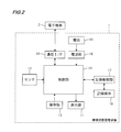
- FIG. 2 is a block diagram showing an internal configuration of the sleep state management device 1 shown in FIG.
- the sleep state management device 1 includes a battery 15, a power supply unit 16, a recording control unit 17, and a communication interface (I / F) 18. And a recording medium 19 and a control unit 14 that performs various arithmetic processes and controls the sleep state management apparatus 1 as a whole.
- the battery 15 is, for example, a button battery.
- the power supply unit 16 supplies the power of the battery 15 to each unit of the sleep state management device 1 via the control unit 14.
- the recording medium 19 is for recording data generated by the control unit 14, and is composed of, for example, a flash memory.
- the recording control unit 17 is a driver for the recording medium 19, and performs data writing to the recording medium 19 and data reading from the recording medium 19 in accordance with instructions from the control unit 14.
- the communication I / F 18 is an interface for performing wireless or wired communication with an electronic device 2 (such as a personal computer or a mobile phone such as a smartphone) external to the sleep state management device 1.
- an electronic device 2 such as a personal computer or a mobile phone such as a smartphone
- the detection signal of the sensor 12 is digitally converted and input to the control unit 14.
- the control unit 14 is configured mainly by a CPU (central processing unit), performs various arithmetic processes based on the input detection signal, and records data based on the result of the arithmetic process in the recording medium 19.
- the operation unit 13 is connected to the control unit 14, and a signal corresponding to the operation of the operation unit 13 is input to the control unit 14, and the control unit 14 performs control according to the signal.
- the control unit 14 also includes a ROM for storing a program executed by the CPU, a RAM as a work memory, and the like.
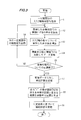
- FIG. 3 is a flowchart for explaining the operation of the sleep state management device 1 shown in FIG. Each step shown in FIG. 3 is performed by the CPU of the control unit 14 based on a program stored in the ROM.
- the measurement subject places the sleep state management device 1 on the bedding and operates the operation unit 13 to instruct to start recording the sleep state.
- a detection signal (digital value) detected by the sensor 12 is stored in the RAM of the control unit 14.
- the recording end instruction of the sleep state is given by the operation of the operation unit 13, the storage of the detection signal in the RAM is stopped.
- the control unit 14 detects the detection signal (X-axis detection signal, Y-axis detection) for a certain period (here, 14 seconds as an example) from the detection signal stored in the RAM. Signal, Z-axis detection signal) is acquired (step S1).
- control unit 14 calculates a difference between adjacent peak values (absolute value ignoring the sign) from the acquired detection signal of each axis (step S2).
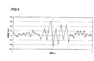
- FIG. 4 is a diagram for explaining the processing content of step S2 in the flowchart shown in FIG. FIG. 4 shows the waveform (X-axis) of the detection signal obtained in 5 to 7 seconds in the above-mentioned fixed period (14 seconds).
- step S2 the control unit 14 first extracts a peak value from the detection signal shown in FIG.
- the peak value is a value at a point (a point surrounded by a broken line in FIG. 4) where the detected acceleration value switches from increase to decrease, increase to no increase, decrease to increase, and decrease to no decrease.
- control unit 14 After extracting the peak value, the control unit 14 extracts each peak value and the peak value adjacent to the peak value (the adjacent peak value obtained after or before the peak value in time series) The difference is calculated.
- control unit 14 uses the calculated difference value as a time representative of the predetermined minute interval (interval of the time between the assumed peak values) including the time when each peak value is obtained. Any one of the start time, end time, intermediate time, etc.) is stored in the RAM.
- control unit 14 integrates the difference value in the X-axis detection signal, the difference value in the Y-axis detection signal, and the difference value in the Z-axis detection signal, which are obtained in step S2, corresponding to the same time. Then, the integrated value of the difference values of the X axis, the Y axis and the Z axis is obtained (step S3).
- FIG. 5 is a diagram showing an example of the difference value after integration obtained in step S3 in the flowchart shown in FIG.
- FIG. 5 shows a graph in which the integrated values of the difference values in the fixed period (14 seconds) are plotted.
- control unit 14 compares the difference value obtained in step S3 with the threshold value Th1, “1” for data when the difference value exceeds the threshold value, and “1” for data when the difference value is equal to or less than the threshold value.
- the data shown in FIG. 6 converted to 0 ′′ is created (step S4), and the created data is stored in the RAM.
- FIG. 6 shows data obtained when the threshold value Th1 is set to 20 in the data shown in FIG.
- the difference value obtained in step S3 indicates that the larger the value, the greater the change in the movement of the bedding on which the measurement subject is sleeping.
- the bedding is moved not only by the movement of the person being measured, but also when the place where the bedding is placed vibrates. In the sleep state management device 1, a slight movement of the bedding is detected by the sensor 12.
- the detection signal of the sensor 12 includes a signal corresponding to the vibration of the place where the bedding is placed. Further, the detection signal of the sensor 12 includes noise unique to the sensor.
- the fluctuation of the detection signal due to the vibration of the place where the bedding is placed and the noise inherent to the sensor are very small compared to the fluctuation of the detection signal due to the movement of the measurement subject.
- the above difference value is compared with the threshold value Th1, thereby eliminating the influence of the vibration of the place where the bedding is placed and the noise unique to the sensor.
- the difference value may increase once or may increase continuously for a certain period. Since it is known that the body movement of the measurement subject occurs continuously for a certain period, it can be determined that the difference value is increased by a factor other than the body movement.
- control unit 14 determines the presence or absence of the body movement of the measurement subject in step S8 described later.
- step S4 the control unit 14 performs the process of step S7 when the processes of step S2 to step S4 are performed for all the detection signals stored in the RAM (step S5: YES).
- Step S5 when the control unit 14 has not performed the processing of Steps S2 to S4 for all the detection signals stored in the RAM (Step S5: NO), the control unit 14 at Step S6 from the RAM for the next certain period (for example, A detection signal of 14 seconds to 28 seconds) is acquired, and the processing after step S2 is performed.
- the control unit 14 at Step S6 from the RAM for the next certain period for example, A detection signal of 14 seconds to 28 seconds
- step S7 the control unit 14 sets a unit section (for example, a section of 3 seconds), for example, every 0.5 seconds for the converted data generated in step S4.
- a unit section for example, a section of 3 seconds
- control unit 14 in FIG. 6 shows a section indicated by a solid arrow (a section from 0 seconds to 3 seconds), a section indicated by a dashed arrow (a section from 0.5 seconds to 3.5 seconds), and a section indicated by a one-dot chain line arrow. (1 second to 4 second interval), etc., and so on, while setting the unit interval while shifting by 0.5 seconds.
- the control unit 14 counts the number of data “1” in each set unit section, and there is body movement of the subject in the section where the number of data “1” exceeds the threshold Th2. It is determined as a section, and a section in which the number of data “1” is equal to or less than the threshold Th2 is determined as a section where there is no body movement of the measurement subject.
- control part 14 determines the period which overlaps with all the unit sections determined to have a body movement as a period with a body movement, and determines the other period as a period without a body movement (step S8).
- control unit 14 manages the sleep state of the measurement subject based on the determination result of step S8 (step S9).
- control unit 14 sets a period in which the occurrence frequency of body motion is equal to or greater than a predetermined threshold as a period of awakening, and sets a period in which the occurrence frequency of body movement is less than a predetermined threshold as a period of sleep state.
- the sleep state of the measurement subject is managed.
- data indicating the sleep state of the measurement subject can be recorded on the recording medium 19 to manage the sleep state of the measurement subject.
- the sleep state management device 1 calculates the difference between adjacent peak values in the detection signal of the sensor 12, and determines the presence or absence of body movement based on the difference value.
- Patent Documents 1 and 2 determine the presence or absence of body movement based on the difference between the signal value sequentially output from the sensor and the signal value output immediately before the signal value. That is, this difference may be a difference between values other than the peak value of the detection signal of the sensor.
- the sleep state management apparatus 1 after using the triaxial acceleration sensor as the sensor 12, and integrating the difference value calculated
- the sensor 12 mounted in the sleep state management apparatus 1 should just be a thing which can detect the motion of bedding, not only an acceleration sensor but the sensor as described in patent document 3 may be used. .
- the acceleration sensor By using the acceleration sensor, it becomes possible to detect the movement of the bedding only with a simple operation of placing the sleep state management device 1 on the bedding, so that the burden on the measurement subject can be reduced.
- step S3 in FIG. 3 When a sensor 12 that outputs only one type of detection signal, such as a single-axis acceleration sensor, is used, the process of step S3 in FIG. 3 is omitted, and in step S4, the difference value calculated in step S2 and the threshold value Th1 are omitted. And data conversion may be performed.
- a sensor 12 that outputs only one type of detection signal such as a single-axis acceleration sensor
- steps S2 to S4 are performed for all detection signals, and then the presence / absence of body motion is determined.
- the processes in S7 to S9 may be performed.
- control unit 14 can determine the awake state and the sleep state while acquiring the detection signal. For example, it is determined that there is a period of the awake state in the vicinity of a preset time. In such a case, an alarm can be sounded to prompt the subject to be awakened.
- the management of the sleep state performed by the control unit 14 includes not only recording data representing the sleep state but also applying some stimulus to the measurement subject according to the sleep state.
- FIG. 7 and 8 are flowcharts for explaining a modification of the operation of the sleep state management device 1 shown in FIG.
- a detection signal (digital value) detected by the sensor 12 is stored in the RAM of the control unit 14.
- the control unit 14 detects the detection signal (X-axis detection signal, Y-axis detection) for a certain period (here, 14 seconds as an example) from the detection signal stored in the RAM. Signal, Z-axis detection signal) is acquired (step S20).
- control unit 14 After acquiring the detection signal for a certain period in step S20, the control unit 14 calculates a moving average for the acquired detection signal for each axis (step S21).
- FIG. 9 is a diagram for explaining the processing content of step S21 in the flowchart shown in FIG.
- FIG. 9 shows the waveform (X-axis) of the detection signal acquired in step S20.
- the control unit 14 detects detection signals that are in the range of 0.5 seconds before and after the time (for example, the range between two broken lines in FIG. 9).
- the average value is calculated as a moving average value at the time.
- the noise (high-frequency component) unrelated to the body movement of the measurement subject can be removed by the process of step S21.
- control unit 14 divides the predetermined period into sections of, for example, 0.5 seconds, and in each divided section, integrates five moving average values corresponding to the divided sections to detect each axis. This is performed on the signal (step S22).
- step S22 By performing the process of step S22, it is possible to reduce the degree of influence of noise that could not be removed by the process of step S21.
- control unit 14 adds the integrated value for the X-axis detection signal, the integrated value for the Y-axis detection signal, and the integrated value for the Z-axis detection signal obtained for each divided section (step S23).
- step S23 when the processing of step S21 to step S23 is performed for all the detection signals stored in the RAM (step S24: YES), the control unit 14 performs the processing after step S25.
- Step S24 NO
- the control unit 14 from the RAM for the next certain period for example, A detection signal of 14 seconds to 28 seconds
- step S25 the control unit 14 sets a plurality of unit sections (for example, sections of 3 seconds) whose start times are shifted by 0.5 seconds in the data generated in step S23.
- the unit interval is set such that the interval from 0 to 3 seconds indicated by a solid arrow, the interval from 0.5 to 3.5 seconds indicated by a dashed arrow, and so on.
- control unit 14 sets the maximum of the six integrated values (added values of the X axis, the Y axis, and the Z axis) corresponding to the six divided sections included in each set unit section.
- a maximum / minimum difference which is a difference between the value and the minimum value (absolute value ignoring the sign), is calculated (step S26).
- step S26 the maximum and minimum differences are obtained for each unit section as shown in FIG.
- control unit 14 determines a unit interval in which the maximum / minimum difference exceeds the threshold Th3 (interval of 1 second to 4 seconds in the example of FIG. 11) as the region with body movement, and the maximum / minimum difference is the threshold value.
- a unit section of Th3 or less is determined as a section without body movement.
- control part 14 determines the period which overlaps with all the unit sections determined to have a body movement as a period with a body movement, and determines the other period as a period without a body movement (step S27).
- control unit 14 After step S27, the control unit 14 performs the processing of step S1 to step S8 in FIG. 3, and then performs the processing of step S28.
- step S28 the control unit 14 manages the sleep state of the measurement subject using the determination result in step S27 and the determination result in step S8.
- control unit 14 sets a period in which the period determined to have body movement in step S27 and the period determined to have body movement in step S8 as a body movement period, and the other period as a period without body movement.
- the recording medium 19 records data in which the period in which the occurrence frequency of body movement is equal to or greater than a predetermined threshold is set as the awake state and the period in which the occurrence frequency of body movement is less than the predetermined threshold is set as the sleep period.
- the sleep state of the measurement subject is managed.
- the body movement of the measurement subject can be accurately determined by the processing in steps S20 to S27 in FIG. 7 even if the detection signal is at a minute level.
- step S27 in FIG. 7 and the determination result in step S8 of FIG. 8 determination of the presence / absence of body movement by a combination of the two methods. Accuracy can be improved.
- step S1 to step S8 in FIG. 8 since the presence or absence of body movement is determined based on the difference between adjacent peak values of the detection signal of the sensor 12, a person to be measured who is light in weight on bedding that does not vibrate easily. Even in the case of sleeping, body movement can be accurately detected.
- steps S20 to S27 in FIG. 7 and the processing in steps S1 to S8 in FIG. 8 are performed separately, but these may be performed in parallel. Further, the order of performing these processes may be reversed.
- the user of the sleep state management device 1 may select which of these processes is performed.
- the processing in steps S20 to S27 in FIG. 7 can reduce the amount of calculation compared to the processing in steps S1 to S8 in FIG. 8, so that when the power saving mode is set, FIG.
- step S27 the battery life of the sleep state management device 1 can be extended by making the flow shift to step S28 after step S27.
- the remaining battery level of the sleep state management device 1 is monitored, and when the remaining battery level is low, any of the processes in steps S20 to S27 in FIG. 7 and the processes in steps S1 to S8 in FIG. Thus, data based on the determination result of either process may be recorded on the recording medium 19.
- step S22 may be omitted.
- step S26 the difference between the maximum value and the minimum value of the moving average values calculated for the unit section may be calculated.
- step S23 in FIG. 7 may be omitted.
- Each step shown in FIG. 3, FIG. 7 and FIG. 8 executed by the control unit 14 of the sleep state management device 1 can also be executed by the electronic device 2 connected to the sleep state management device 1.
- a program for causing the computer to execute the steps shown in FIGS. 3, 7, and 8 performed by the control unit 14 of the sleep state management apparatus 1 may be installed in the electronic device 2.
- Such a program is recorded on a non-transitory recording medium in which the program can be read by a computer.
- Such “computer-readable recording medium” includes, for example, an optical medium such as a CD-ROM (Compact Disc-ROM), a magnetic recording medium such as a memory card, and the like. Such a program can also be provided by downloading via a network.
- an optical medium such as a CD-ROM (Compact Disc-ROM)
- a magnetic recording medium such as a memory card, and the like.
- Such a program can also be provided by downloading via a network.
- the disclosed sleep state management apparatus calculates a peak value difference that is a difference between adjacent sensor peak values in a sensor unit that detects movement of the bedding on which the measurement subject is sleeping and a detection signal output from the sensor unit.
- a peak value difference calculating unit, and a first body motion determining unit that determines a period in which the number of times that the peak value difference exceeds the first threshold is greater than a predetermined value as a period of the subject's body motion,
- a sleep state management unit that manages a sleep state of the measurement subject using a determination result by the first body movement determination unit.
- the sensor unit includes a biaxial or triaxial acceleration sensor.
- the peak value difference includes an integrated value of the differences calculated for the detection signals of the respective axes output from the sensor unit.
- the disclosed sleep state management apparatus obtains a maximum / minimum difference, which is a difference between a maximum value and a minimum value of the detection signal in the unit section, for each unit section in a period in which the detection signal is output from the sensor unit.
- the sleep state management comprising: a difference calculation unit; and a second body motion determination unit that determines the unit interval in which the maximum and minimum difference exceeds a second threshold as a region in which the measurement subject has moved.
- the unit manages the sleep state of the measurement subject using the determination result by the first body movement determination unit and the determination result by the second body movement determination unit.
- the disclosed sleep state management device includes an integrated value calculation unit that calculates an integrated value of the detection signal obtained at regular intervals for each divided section obtained by dividing the unit section, and the maximum and minimum difference calculating unit includes: The difference between the maximum value and the minimum value among the plurality of integrated values calculated corresponding to the unit section is calculated as the maximum / minimum difference.
- the disclosed sleep state management method includes a peak value difference calculating step of calculating a peak value difference that is a difference between adjacent peak values in a detection signal output from a sensor unit that detects vibration of the bedding on which the measurement subject is sleeping. And a body movement determination step for determining a period in which the number of times the peak value difference exceeds a threshold value is greater than a predetermined value as a period in which the measurement subject has moved, and a determination result obtained by the body movement determination step is used. And a sleep state management step for managing the sleep state of the measurement subject.
- the disclosed sleep state management program is a program for causing a computer to execute each step of the sleep state management method.
- the present invention can be applied to, for example, a home sleep management device and can be used for user health management.
Abstract
Description
11 表示部
12 センサ
13 操作部
14 制御部 DESCRIPTION OF
Claims (7)
- 被測定者が寝ている寝具の動きを検知するセンサ部と、
前記センサ部から出力される検知信号における隣接するピーク値の差分であるピーク値差分を算出するピーク値差分算出部と、
前記ピーク値差分が第一の閾値を越える回数が所定値よりも多い期間を、前記被測定者の体動ありの期間として判定する第一の体動判定部と、
前記第一の体動判定部による判定結果を用いて前記被測定者の睡眠状態を管理する睡眠状態管理部と、を備える睡眠状態管理装置。 A sensor unit for detecting movement of the bedding on which the measurement subject is sleeping; and
A peak value difference calculating unit that calculates a peak value difference that is a difference between adjacent peak values in the detection signal output from the sensor unit;
A first body movement determination unit that determines a period in which the number of times that the peak value difference exceeds the first threshold is greater than a predetermined value as a period of body movement of the measurement subject;
A sleep state management device comprising: a sleep state management unit that manages a sleep state of the measurement subject using a determination result by the first body movement determination unit. - 請求項1記載の睡眠状態管理装置であって、
前記センサ部は2軸又は3軸加速度センサである睡眠状態管理装置。 The sleep state management device according to claim 1,
The sleep sensor is a two-axis or three-axis acceleration sensor. - 請求項2記載の睡眠状態管理装置であって、
前記ピーク値差分は、前記センサ部から出力される各軸の検知信号について算出された前記差分の積算値である睡眠状態管理装置。 The sleep state management device according to claim 2,
The said peak value difference is a sleep state management apparatus which is an integrated value of the said difference calculated about the detection signal of each axis | shaft output from the said sensor part. - 請求項1~3のいずれか1項記載の睡眠状態管理装置であって、
前記センサ部から検知信号が出力される期間における単位区間毎に、当該単位区間における前記検知信号の最大値と最小値の差分である最大最小差を求める最大最小差算出部と、
前記最大最小差が第二の閾値を越える前記単位区間を、前記被測定者の体動があった区間として判定する第二の体動判定部とを備え、
前記睡眠状態管理部は、前記第一の体動判定部による判定結果と前記第二の体動判定部による判定結果とを用いて、前記被測定者の睡眠状態を管理する睡眠状態管理装置。 The sleep state management device according to any one of claims 1 to 3,
A maximum / minimum difference calculation unit for obtaining a maximum / minimum difference that is a difference between the maximum value and the minimum value of the detection signal in the unit section for each unit section in a period in which the detection signal is output from the sensor unit;
A second body movement determination unit that determines the unit section in which the maximum and minimum difference exceeds a second threshold as a section in which the subject's body movement has occurred;
The sleep state management unit is a sleep state management device that manages the sleep state of the measurement subject using the determination result by the first body movement determination unit and the determination result by the second body movement determination unit. - 請求項4記載の睡眠状態管理装置であって、
前記単位区間を分割した分割区間毎に、一定時間毎に得られた前記検知信号の積算値を算出する積算値算出部を備え、
前記最大最小差算出部は、前記単位区間に対応して算出された複数の前記積算値のうちの最大値と最小値の差分を前記前記最大最小差として算出する睡眠状態管理装置。 The sleep state management device according to claim 4,
For each divided section obtained by dividing the unit section, an integrated value calculation unit that calculates an integrated value of the detection signal obtained at regular intervals,
The maximum / minimum difference calculation unit is a sleep state management device that calculates a difference between a maximum value and a minimum value among the plurality of integrated values calculated corresponding to the unit section as the maximum / minimum difference. - 被測定者が寝ている寝具の振動を検知するセンサ部から出力される検知信号における隣接するピーク値の差分であるピーク値差分を算出するピーク値差分算出ステップと、
前記ピーク値差分が閾値を越える回数が所定値よりも多い期間を、前記被測定者の体動があった期間として判定する体動判定ステップと、
前記体動判定ステップによる判定結果を用いて前記被測定者の睡眠状態を管理する睡眠状態管理ステップと、を備える睡眠状態管理方法。 A peak value difference calculating step for calculating a peak value difference that is a difference between adjacent peak values in a detection signal output from a sensor unit that detects vibration of the bedding on which the measurement subject is sleeping;
A body movement determination step for determining a period in which the number of times that the peak value difference exceeds a threshold value is greater than a predetermined value as a period in which the body movement of the measurement subject has occurred;
A sleep state management method comprising: a sleep state management step for managing a sleep state of the measurement subject using a determination result in the body movement determination step. - コンピュータに、請求項6記載の睡眠状態管理方法の各ステップを実行させるための睡眠状態管理プログラム。 A sleep state management program for causing a computer to execute each step of the sleep state management method according to claim 6.
Priority Applications (3)
| Application Number | Priority Date | Filing Date | Title |
|---|---|---|---|
| US14/388,120 US9433377B2 (en) | 2012-03-26 | 2012-11-12 | Sleep state management device, sleep state management method, and sleep state management program |
| CN201280071831.7A CN104203095B (en) | 2012-03-26 | 2012-11-12 | Sleep state management devices, sleep state management process |
| DE112012006099.7T DE112012006099T5 (en) | 2012-03-26 | 2012-11-12 | Sleep state management device, sleep state management method, and sleep state management program |
Applications Claiming Priority (2)
| Application Number | Priority Date | Filing Date | Title |
|---|---|---|---|
| JP2012-069608 | 2012-03-26 | ||
| JP2012069608A JP5862400B2 (en) | 2012-03-26 | 2012-03-26 | Sleep state management device, sleep state management method, and sleep state management program |
Publications (1)
| Publication Number | Publication Date |
|---|---|
| WO2013145417A1 true WO2013145417A1 (en) | 2013-10-03 |
Family
ID=49258755
Family Applications (1)
| Application Number | Title | Priority Date | Filing Date |
|---|---|---|---|
| PCT/JP2012/079287 WO2013145417A1 (en) | 2012-03-26 | 2012-11-12 | Sleep state management device, sleep state management method, and sleep state management program |
Country Status (5)
| Country | Link |
|---|---|
| US (1) | US9433377B2 (en) |
| JP (1) | JP5862400B2 (en) |
| CN (1) | CN104203095B (en) |
| DE (1) | DE112012006099T5 (en) |
| WO (1) | WO2013145417A1 (en) |
Cited By (1)
| Publication number | Priority date | Publication date | Assignee | Title |
|---|---|---|---|---|
| JP2016508039A (en) * | 2012-11-27 | 2016-03-17 | コーニンクレッカ フィリップス エヌ ヴェKoninklijke Philips N.V. | Detection of device position change in horizontal or vertical direction |
Families Citing this family (12)
| Publication number | Priority date | Publication date | Assignee | Title |
|---|---|---|---|---|
| JP5862401B2 (en) * | 2012-03-26 | 2016-02-16 | オムロンヘルスケア株式会社 | Sleep state management device, sleep state management method, and sleep state management program |
| US20170135629A1 (en) * | 2014-01-07 | 2017-05-18 | Invicta Medical, Inc. | Determining a level of sleep or a level of consciousness |
| US20170347948A1 (en) * | 2014-12-30 | 2017-12-07 | Nitto Denko Corporation | Device and Method for Sleep Monitoring |
| RU2727245C1 (en) * | 2015-09-29 | 2020-07-21 | Конинклейке Филипс Н.В. | Breast pump |
| RU2740675C2 (en) * | 2016-04-12 | 2021-01-19 | Конинклейке Филипс Н.В. | System for increasing a user's sleep efficiency |
| CN106562771B (en) * | 2016-11-21 | 2019-06-18 | 华南理工大学 | A kind of pet sleep recognition methods of Embedded platform |
| CN107007263B (en) * | 2017-04-25 | 2019-11-19 | 中国科学院计算技术研究所 | A kind of the sleep quality assessment method and system of generalization |
| CN109199355B (en) * | 2018-09-18 | 2021-09-28 | 深圳和而泰数据资源与云技术有限公司 | Heart rate information detection method and device and detection equipment |
| US11491324B2 (en) | 2019-10-16 | 2022-11-08 | Invicta Medical, Inc. | Adjustable devices for treating sleep apnea, and associated systems and methods |
| CN110975107B (en) * | 2019-12-26 | 2022-04-26 | 喜临门家具股份有限公司 | Music sleep-aiding pillow and music sleep-aiding method |
| CN111166295A (en) * | 2020-02-12 | 2020-05-19 | 苏州明皜传感科技有限公司 | Sleep monitoring method and device and sleep monitoring equipment |
| JP2023548970A (en) | 2020-11-04 | 2023-11-21 | インヴィクタ メディカル インコーポレイテッド | Remotely powered implantable electrodes and related systems and methods for treating sleep apnea |
Citations (3)
| Publication number | Priority date | Publication date | Assignee | Title |
|---|---|---|---|---|
| JP2006230789A (en) * | 2005-02-25 | 2006-09-07 | Medical Electronic Science Inst Co Ltd | Sleep condition detecting system and sleep condition detector |
| JP2007292514A (en) * | 2006-04-21 | 2007-11-08 | Matsushita Electric Works Ltd | Data processing method for acceleration sensor, respiratory movement detecting method, and respiratory movement detector |
| JP2008307204A (en) * | 2007-06-14 | 2008-12-25 | Daikin Ind Ltd | Biological signal processing device |
Family Cites Families (11)
| Publication number | Priority date | Publication date | Assignee | Title |
|---|---|---|---|---|
| US20040034285A1 (en) * | 2000-10-31 | 2004-02-19 | Takeshi Sahashi | Body movement analysis system and body movement analysis method |
| JP3960298B2 (en) * | 2003-11-19 | 2007-08-15 | 株式会社デンソー | Sleeping and posture detection device |
| WO2006090876A1 (en) | 2005-02-25 | 2006-08-31 | Medical Electronic Science Institute Co., Ltd. | Sleeping state detecting system and sleeping state detecting device |
| JP4469747B2 (en) | 2005-03-30 | 2010-05-26 | 株式会社東芝 | Alarm device, alarm method and alarm program |
| JP4598581B2 (en) | 2005-03-31 | 2010-12-15 | クロイ電機株式会社 | Sleep diary creation support device |
| WO2006123691A1 (en) * | 2005-05-18 | 2006-11-23 | Matsushita Electric Works, Ltd. | Sleep diagnostic system |
| JP4806237B2 (en) | 2005-09-01 | 2011-11-02 | 関西電力株式会社 | Sleep state estimation method, system and operation program thereof |
| JP4528710B2 (en) * | 2005-11-09 | 2010-08-18 | 株式会社東芝 | Sleep state measurement device, sleep state measurement method, and sleep state measurement system |
| JP4103925B1 (en) * | 2006-12-08 | 2008-06-18 | ダイキン工業株式会社 | Sleep determination device |
| EP2249908B1 (en) * | 2008-01-25 | 2014-01-01 | Medtronic, Inc. | Sleep stage detection |
| WO2011009085A2 (en) * | 2009-07-17 | 2011-01-20 | Oregon Health & Science University | Method and apparatus for assessment of sleep disorders |
-
2012
- 2012-03-26 JP JP2012069608A patent/JP5862400B2/en active Active
- 2012-11-12 WO PCT/JP2012/079287 patent/WO2013145417A1/en active Application Filing
- 2012-11-12 CN CN201280071831.7A patent/CN104203095B/en active Active
- 2012-11-12 DE DE112012006099.7T patent/DE112012006099T5/en not_active Ceased
- 2012-11-12 US US14/388,120 patent/US9433377B2/en active Active
Patent Citations (3)
| Publication number | Priority date | Publication date | Assignee | Title |
|---|---|---|---|---|
| JP2006230789A (en) * | 2005-02-25 | 2006-09-07 | Medical Electronic Science Inst Co Ltd | Sleep condition detecting system and sleep condition detector |
| JP2007292514A (en) * | 2006-04-21 | 2007-11-08 | Matsushita Electric Works Ltd | Data processing method for acceleration sensor, respiratory movement detecting method, and respiratory movement detector |
| JP2008307204A (en) * | 2007-06-14 | 2008-12-25 | Daikin Ind Ltd | Biological signal processing device |
Cited By (1)
| Publication number | Priority date | Publication date | Assignee | Title |
|---|---|---|---|---|
| JP2016508039A (en) * | 2012-11-27 | 2016-03-17 | コーニンクレッカ フィリップス エヌ ヴェKoninklijke Philips N.V. | Detection of device position change in horizontal or vertical direction |
Also Published As
| Publication number | Publication date |
|---|---|
| JP2013198653A (en) | 2013-10-03 |
| CN104203095A (en) | 2014-12-10 |
| DE112012006099T5 (en) | 2014-12-11 |
| CN104203095B (en) | 2016-06-08 |
| US9433377B2 (en) | 2016-09-06 |
| JP5862400B2 (en) | 2016-02-16 |
| US20150029030A1 (en) | 2015-01-29 |
Similar Documents
| Publication | Publication Date | Title |
|---|---|---|
| JP5862400B2 (en) | Sleep state management device, sleep state management method, and sleep state management program | |
| JP5862401B2 (en) | Sleep state management device, sleep state management method, and sleep state management program | |
| EP3212072B1 (en) | Sleep measurement computer system | |
| CN106489066B (en) | Apparatus for predictive data measurement and computer-implemented method for predictive data measurement | |
| CN107710022A (en) | Seismaesthesia sensor and earthquake determination methods | |
| KR102143499B1 (en) | Method and apparatus for quality measurement of sleep using a portable terminal | |
| TWI655928B (en) | Physiological monitoring device, physiological monitoring method and computer readable recording medium for implementing the physiological monitoring method | |
| WO2018098719A1 (en) | Sleep monitoring method, apparatus and terminal | |
| JP6013668B1 (en) | Basal body temperature measuring system and basal body temperature measuring device | |
| WO2022021707A1 (en) | Sleep monitoring method and apparatus, and smart wearable device and readable storage medium | |
| JP6311150B2 (en) | ANALYSIS SYSTEM, ANALYSIS DEVICE, ELECTRONIC DEVICE, ANALYSIS METHOD, AND PROGRAM | |
| JP2016041112A (en) | Activity meter | |
| US20170098365A1 (en) | Activity information measuring apparatus, and method and program for assisting prevention of forgotten attachment of the same | |
| JP6269160B2 (en) | Sleep state evaluation device, sleep state evaluation method, and sleep state evaluation system | |
| KR101864358B1 (en) | Mobile device for collecting sleeping information, method for collecting sleeping information, and application thereof | |
| CN106462335A (en) | Dormancy awakening system, method and device for terminal | |
| JP6107403B2 (en) | Biological information measuring device and program | |
| TW201526874A (en) | Sleeping motion detecting method and wristband electronic device | |
| KR20220077655A (en) | Sleep efficiency managing system and method for measuring sleep efficiency by the system | |
| JP2014048240A (en) | Electronic clock and program |
Legal Events
| Date | Code | Title | Description |
|---|---|---|---|
| 121 | Ep: the epo has been informed by wipo that ep was designated in this application |
Ref document number: 12872720 Country of ref document: EP Kind code of ref document: A1 |
|
| WWE | Wipo information: entry into national phase |
Ref document number: 14388120 Country of ref document: US |
|
| WWE | Wipo information: entry into national phase |
Ref document number: 1120120060997 Country of ref document: DE Ref document number: 112012006099 Country of ref document: DE |
|
| 122 | Ep: pct application non-entry in european phase |
Ref document number: 12872720 Country of ref document: EP Kind code of ref document: A1 |