WO2013145163A1 - Cigarette filter inspection device and inspection method thereof - Google Patents
Cigarette filter inspection device and inspection method thereof Download PDFInfo
- Publication number
- WO2013145163A1 WO2013145163A1 PCT/JP2012/058162 JP2012058162W WO2013145163A1 WO 2013145163 A1 WO2013145163 A1 WO 2013145163A1 JP 2012058162 W JP2012058162 W JP 2012058162W WO 2013145163 A1 WO2013145163 A1 WO 2013145163A1
- Authority
- WO
- WIPO (PCT)
- Prior art keywords
- inspection
- filter element
- filter
- imaging
- setting
- Prior art date
Links
Images


Classifications
-
- A—HUMAN NECESSITIES
- A24—TOBACCO; CIGARS; CIGARETTES; SIMULATED SMOKING DEVICES; SMOKERS' REQUISITES
- A24C—MACHINES FOR MAKING CIGARS OR CIGARETTES
- A24C5/00—Making cigarettes; Making tipping materials for, or attaching filters or mouthpieces to, cigars or cigarettes
- A24C5/32—Separating, ordering, counting or examining cigarettes; Regulating the feeding of tobacco according to rod or cigarette condition
- A24C5/34—Examining cigarettes or the rod, e.g. for regulating the feeding of tobacco; Removing defective cigarettes
- A24C5/3412—Examining cigarettes or the rod, e.g. for regulating the feeding of tobacco; Removing defective cigarettes by means of light, radiation or electrostatic fields
-
- A—HUMAN NECESSITIES
- A24—TOBACCO; CIGARS; CIGARETTES; SIMULATED SMOKING DEVICES; SMOKERS' REQUISITES
- A24D—CIGARS; CIGARETTES; TOBACCO SMOKE FILTERS; MOUTHPIECES FOR CIGARS OR CIGARETTES; MANUFACTURE OF TOBACCO SMOKE FILTERS OR MOUTHPIECES
- A24D3/00—Tobacco smoke filters, e.g. filter-tips, filtering inserts; Filters specially adapted for simulated smoking devices; Mouthpieces for cigars or cigarettes
- A24D3/02—Manufacture of tobacco smoke filters
- A24D3/0295—Process control means
-
- G—PHYSICS
- G01—MEASURING; TESTING
- G01N—INVESTIGATING OR ANALYSING MATERIALS BY DETERMINING THEIR CHEMICAL OR PHYSICAL PROPERTIES
- G01N21/00—Investigating or analysing materials by the use of optical means, i.e. using sub-millimetre waves, infrared, visible or ultraviolet light
- G01N21/84—Systems specially adapted for particular applications
- G01N21/88—Investigating the presence of flaws or contamination
Definitions
- the present invention relates to a cigarette filter inspection apparatus including a filter such as a perfume capsule or activated carbon, and an inspection method thereof.
- a manufacturing machine for manufacturing a filter incorporating such a fragrance capsule includes a capsule supply device that supplies a fragrance capsule to a space between a large number of filter elements placed on a forming paper to form a filter element row, and this supply
- An example of the apparatus is disclosed in Patent Document 1.
- the supply device of Patent Document 1 has a hopper that stores fragrance capsules, and a rotating wheel disposed between the hopper and a manufacturing line of the manufacturing machine.
- the rotating wheel intermittently inserts the fragrance capsules in the hopper into the manufacturing line.
- the rotating wheel has a large number of pockets on the outer peripheral surface thereof, and these pockets are arranged at equal intervals in the circumferential direction of the rotating wheel.
- the fragrance capsule when the fragrance capsule is received in the pocket of the rotating wheel, it is inevitable that the inner wall of the pocket strongly collides with the fragrance capsule. Such a collision causes damage to the perfume capsules and misincorporation of the perfume capsules into the pockets and thus to the filter element spacing.
- a film piece of a broken fragrance capsule is mixed into a filter element, a fragrance leaks from a broken fragrance capsule into a filter element interval, or a plurality of fragrance capsules are mixed into one filter element interval. Or even if no perfume capsules are supplied to the filter element spacing.
- An object of the present invention is to detect and eliminate mixing of a filler into a filter element and erroneous mixing of a packing into a filter element interval, thereby making it possible to manufacture a filter rod of constant quality, and thus a filter cigarette. To provide a cigarette filter inspection apparatus and an inspection method thereof.
- the filter inspection apparatus supplies a filler to the interval between a plurality of filter elements placed on a forming paper to filter the filter.
- a filter manufacturing machine including a filler supply unit that forms an element row, a master sample setting unit that sets a color component of the filler as a master color sample, and an imaging unit that forms an inspection image by imaging the filter element row Inspection area setting means for setting the inspection area in the inspection image in the filter element array, and quality determination means for determining the quality of the filter element array by comparing the color area of the master color sample existing in the inspection area with a predetermined threshold value.
- the filter manufacturing machine further includes hoisting means for winding up the forming paper in the filter element row to form a filter rod, and the imaging means is arranged between the filler supply means and the hoisting means.
- the inspection area setting means sets the inspection area separately for the filter element and the filter element interval based on the inspection image formed by the imaging means.
- the inspection area setting unit detects the position of the edge part on the filter element interval side of the filter element in the filter element row based on the inspection image formed by the imaging unit, and based on the detected position information of the edge part The position of the inspection area is corrected so as to match the area of either the filter element or the filter element interval.
- the filter inspection method is a filter manufacturing method including a filler supply step of forming a filter element row by supplying a filler to an interval between a plurality of filter elements placed on a molding paper.
- a master sample setting process for setting a sample color as a master color sample an imaging process for imaging a filter element array to form an inspection image, an inspection area setting process for setting an inspection area as a filter element array in the inspection image, and an inspection area
- the filter manufacturing method further includes a hoisting step of winding up the forming paper in the filter element row to form a filter rod, and the imaging step is performed between the filling supply step and the hoisting step.
- the inspection area setting step the inspection area is divided into filter elements and filter element intervals based on the inspection image formed in the imaging process.
- the position of the edge portion on the filter element interval side of the filter element in the filter element row is detected based on the inspection image formed in the imaging step, and based on the detected position information of the edge portion
- the position of the inspection area is corrected so as to match the area of either the filter element or the filter element interval.
- the cigarette filter inspection apparatus and the inspection method of the present invention it is possible to detect and eliminate the mixing of the filler into the filter element and the erroneous mixing of the filler into the filter element interval, thereby eliminating the constant quality filter rod.
- a filter cigarette can be manufactured.
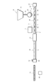
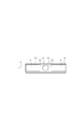
- FIG. 1 schematically shows a part of a filter manufacturing machine.
- This manufacturing machine is equipped with a filter inspection apparatus 1 for performing the filter inspection method of the present invention.
- the production machine includes a production line 2 extending horizontally, and the production line 2 includes an upstream conveyor 4 and a downstream conveyor 6.
- the upstream conveyor 4 is connected to an element supply 10 that supplies a filter element 8.
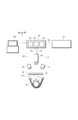
- the filter rod has an acetate fiber tow, that is, a filter material 12 and a wrapping paper 14 that wraps the filter material 12 in a rod shape.
- the element supply source 10 supplies the filter elements 8 obtained by cutting the filter rods equally into the upstream conveyor 4 one by one.
- a filter element row 16 in which the filter elements 8 are arranged at equal intervals on the upstream conveyor 4 is formed.
- the filter element row 16 is transferred on the upstream conveyor 4 toward the downstream conveyor 6.
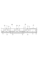
- the forming paper 18 has already been supplied onto the upstream conveyor 4, and the filter element row 16 is placed on the forming paper 18. Therefore, the filter element row 16 is conveyed along the forming paper 18 on the upstream conveyor 4 in the direction of the arrow X toward the subsequent winding section (winding means) 20, and the upstream conveyor 4 is conveyed along the conveyance path for the filter element row 16.
- the forming paper 18 is supplied to the upstream conveyor 4 from a roll (not shown).
- a supply device (filling supply means) 24 for supplying a spherical capsule (filling) 22 as a granular material is disposed immediately above the upstream conveyor 4.
- the supply device 24 includes a hopper 26 that stores the capsules 22, and a rotary wheel 30 that is disposed between the hopper 26 and the production line 2 of the manufacturing machine via a supply path 28.
- the inner capsule 22 is intermittently supplied to the production line 2.
- the rotating wheel 30 has a large number of pockets 32 on the outer peripheral surface thereof, and these pockets 32 are arranged at equal intervals in the circumferential direction of the rotating wheel 30.
- the rotating wheel 30 As the rotating wheel 30 rotates, it receives the capsules 22 from the hopper 26 into the individual pockets 32, and transfers the received capsules 22 together with the pockets 32 toward the production line 2.
- the capsule 22 is dropped and supplied from the pocket 32 to the production line 2.
- the supply device 24 supplies the capsule 22 to the filter element interval 34 of the filter elements 8 constituting the filter element row 16, and when the filter element row 16 is supplied to the hoisting section 20, all of the filter element rows 16 are supplied.
- a capsule 22 is arranged in the filter element interval 34.
- the capsule 22 is a spherical fragrance capsule containing a liquid fragrance, and has a diameter of approximately 2.0 to 7.0 mm, for example.
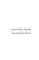
- the hoisting section 20 receives the filter element row 16 and the form paper 18 and continuously wraps the filter element row 16 with the form paper 18 using a garniture tape 36 (see FIG. 2), as is known in the art.
- a rod continuum 38 is formed. After this, the continuum 38 is delivered from the hoisting section 20 and passes through the cutting section 40.
- the cutting section 40 cuts the continuous body 38 at a predetermined length to produce a filter rod 42.
- the filter rod 42 has a length that is a multiple of the filter used in one of the filter cigarettes, and four times longer in this embodiment.
- the manufactured filter rod 42 is supplied to a filter attaching machine (not shown) and used for manufacturing a filter cigarette.
- the filter inspection apparatus 1 of the present invention is disposed immediately above the upstream conveyor 4 between the supply device 24 of the production line 2 and the hoisting section 20.
- the filter inspection apparatus 1 includes a color camera (imaging means) 44, illuminations 46 and 46, a controller 48, a monitor 50, and a proximity sensor 52 arranged on both sides thereof.
- the proximity sensor 52 is disposed in the cutting section 40 and sends a test command signal 54 for the filter element array 16 to the controller 48.
- the controller 48 When the controller 48 receives the inspection command signal 54 from the proximity sensor 52, the controller 48 transmits an illumination command signal 56 for illuminating the illuminations 46, 46 to the illuminations 46, 46, respectively, and is transported directly below the camera 44 in the production line 2.
- An imaging command signal 58 for imaging the filter element array 16 is transmitted to the camera 44, and imaging by the camera 44 is performed under illumination by the illuminations 46 and 46.
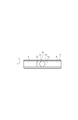
- reference numeral 62 denotes an acrylic plate that is partially visible so as to image the filter element row 16 that is transported through the production line 2 while being protected from dust and the like. Imaging at 44 is performed through the acrylic plate 62, and the acrylic plate 62 also plays a role of preventing the filter element row 16 including the capsule 22 from jumping out of the production line 2.
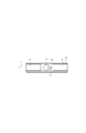
- the captured image of the filter element array 16 in a predetermined imaging range (for example, 35 mm) captured by the camera 44 is transmitted to the controller 48 as the inspection image 60 and used for the filter inspection in the inspection apparatus 1.
- the controller 48 includes a master sample setting unit (master sample setting unit) 64, an inspection region setting unit (inspection region setting unit) 66, and a quality determination unit (quality determination unit) 68.
- master sample setting unit 64 the color component (for example, blue) of the capsule 22 is preset as a master color sample, and the size and shape of the capsule 22 are preset as a master pattern. It is stored in the setting unit 64.
- the inspection region setting unit 66 sets the inspection region 70 in the inspection image 60 captured by the camera 44 as the filter element interval 34 (FIGS. 4A and 4D), or the filter element array 16 Whether the filter element 8 is the front filter element 8 when viewed in the transport direction X (FIG. 4B) or the filter element 8 is the rear filter element 8 when viewed in the transport direction X of the filter element row 16 (FIG. 4C). In other words, three inspection regions 70 of the front filter element 8, the filter element interval 34, and the rear filter element 8 are inspected for one inspection image 60.
- the inspection area setting unit 66 detects the position of the edge portion 72 on the filter element interval 34 side of the filter element 8 in the filter element row 16 based on the inspection image 60 captured by the camera 44. Then, as shown in FIGS. 4A to 4D, by using the detected position data of the edge portion 72, the inspection region 70 is moved to any one of the front filter element 8, the filter element interval 34, and the rear filter element 8. The position of the inspection area 70 is corrected so as to coincide with this area.
- the inspection area setting unit 66 inspects the three inspection areas 70 accurately and at high speed with respect to one inspection image 60, and the entire inspection image 60 is inspected without omission.
- the quality determination unit 68 compares the master color sample data stored in the master sample setting unit 64 with the color component data of the inspection region 70 in the inspection region 70 shown in FIGS.
- the capsule color area inspection is performed by comparing the color area of the master color sample existing in 70 with a predetermined color area threshold (predetermined threshold).
- a capsule shape inspection is performed in which the master pattern data stored in the master sample setting unit 64 is collated with the contour data of an object existing in the inspection area 70 to determine the matching rate. It is also possible to do this.
- the capsule color area inspection and the capsule shape inspection will be described with reference to FIGS. 5A to 5C and FIG.
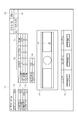
- FIG. 6 shows an example of the configuration of the image inspection screen 74 displayed on the monitor 50 of the filter inspection apparatus 1.
- the image inspection screen 74 includes a setting NO display section 76, a total inspection result display section 78, an inspection condition display section 80, an individual inspection data display section 82 for each inspection area and inspection item, an inspection threshold display section 84, and a total NG data display section. 86, an apparatus state display unit 88, a comprehensive determination result display unit 90, an NG latest image display unit 92, an NG history display unit 94, and the like.
- the measurement value of the color area of the rear filter element 8 is displayed in the W2 area column displayed on the individual inspection data display unit 82 in the inspection region 70 shown in FIG.
- a predetermined threshold value for example, 10
- the measured color area value (36) exceeds the threshold (10). Therefore, an NG signal is issued from the quality determination unit 68 to the outside of the controller 48.
- the corresponding filter element row 16 portion of the inspection area 70 is removed from the production line 2 after passing through the cutting section 40 and transferred to the exclusion processing unit 98 (see FIG. 1).
- the NG signal is received and NG is displayed on the comprehensive determination result display section 90.
- the NG count of the W2 area of the individual inspection data display section 82 and the NG count of the total NG data display section 86 are displayed.
- the latest inspection image 60 that has been counted and stored and becomes NG is enlarged and displayed on the NG latest image display unit 92, and this inspection image 60 is displayed as a history in the NG latest column of the NG history display unit 94.
- the measured value of the color area of the filter element interval 34 is displayed in the column of the W0 area displayed on the individual inspection data display unit 82, and the measured value is displayed in the quality determination unit 68 by the W0 of the inspection threshold value display unit 84. It is determined whether or not the value is larger than a predetermined threshold (for example, 5000) corresponding to the area. At the same time, in order to detect a state in which the capsule 22 is not contained in the filter element gap 34, it is also determined whether or not it is smaller than the predetermined threshold value. At this time, as shown in FIG. 5A, when two capsules 22 are erroneously mixed in the filter element interval 34 and the value of the measured color area exceeds the threshold value, the same as the case shown in FIG. 5C described above. Exclusion processing and display are performed.
- a predetermined threshold for example, 5000
- the measurement value of the color area of the front filter element 8 is displayed.
- this measurement value is displayed on the inspection threshold value display unit 84. It is determined whether or not it is larger than a predetermined threshold (for example, 10) corresponding to the W1 area.
- a predetermined threshold for example, 10
- the capsule shape inspection for example, measurement values representing the shape and size of the capsules 22 arranged at the filter element interval 34 in the inspection region 70 shown in FIG. 4D are measured. It is determined whether it is smaller than the threshold value. When the measured value is less than the threshold value, the same exclusion process and display as in the capsule color area inspection shown in FIGS. 5A to 5C described above are performed.
- the filter inspection performed by the filter inspection apparatus 1 having the above-described configuration is performed from the start by the master sample setting step (step S ⁇ b> 1) performed by the master sample setting unit 64 and by the color camera 44.
- Imaging step (step S2), inspection region setting step (step S3) performed by the inspection region setting unit 66, quality determination step (step S4) performed by the quality determination unit 68, and exclusion step (step S4) performed by the exclusion processing unit 98 The process is performed in the order of step S5) and the process ends.
- the capsule supply process (step S11) performed in the capsule supply device 24 and the winding process (step S12) performed in the winding section 20 in the entire filter manufacturing process.
- the exclusion process (step S5) is performed after the cutting process (step S13) performed in the cutting section 40.
- the capsule color area inspection and the capsule shape inspection as described above are performed, the mixing of the coating pieces 96 and 100 of the capsule 22 into the filter element 8, and the filter element
- the filter element By detecting and eliminating the erroneous mixing of the capsules 22 into the interval 34, it is possible to manufacture a filter rod 42 with a constant quality, and thus a filter cigarette.
- the present invention is not limited to the filter inspection apparatus 1 of the above embodiment, and various modifications can be made.
- FIG. 5D even when the capsule 22 arranged at the filter element interval 34 is broken and broken, it can be detected by the capsule color area inspection described above, and FIG. As shown in FIG. 5, even if the capsule 22 is defective and does not exist in the filter element interval 34, it can be detected by the capsule color area inspection.
- both the capsule color area inspection and the capsule shape inspection are performed in the quality determination unit 68, but only the capsule color area inspection may be performed.
- interval 34 were demonstrated, not only this but another packing, such as activated carbon, was carried out at the filter element space
- the present invention can also be applied to supply.
Abstract
This filter inspection device (1) is provided with: a master sample setting means (64) that sets the color components of a filler (22) as a master color sample; an imaging means (44) that forms an inspection image (60) by imaging a filter element array (16); an inspection region setting means (66) that sets the inspection region (70) in the inspection image to be at the filter elements; and a quality judgment means (68) that judges the quality of the filter element array by comparing the color area of the master color sample present in the inspection region to a predetermined threshold.
Description
本発明は、フィルタに香料カプセル又は活性炭などの充填物を備えるシガレットのフィルタ検査装置及びその検査方法に関する。
The present invention relates to a cigarette filter inspection apparatus including a filter such as a perfume capsule or activated carbon, and an inspection method thereof.
従来、粒状物としての香味カプセル又は活性炭などの充填物を備えるフィルタシガレットが知られており、香料カプセル又は活性炭などの充填物は、フィルタシガレットのフィルタ内に配置されている。このような香料カプセルを内蔵したフィルタを製造する製造機は、成形紙上に載置された多数のフィルタ要素の間隔に香料カプセルを供給してフィルタ要素列を形成するカプセル供給装置を含み、この供給装置の一例が特許文献1に開示されている。
Conventionally, filter cigarettes provided with fillers such as flavor capsules or activated carbon as particulates are known, and fillers such as fragrance capsules or activated carbon are arranged in the filter of the filter cigarette. A manufacturing machine for manufacturing a filter incorporating such a fragrance capsule includes a capsule supply device that supplies a fragrance capsule to a space between a large number of filter elements placed on a forming paper to form a filter element row, and this supply An example of the apparatus is disclosed in Patent Document 1.
特許文献1の供給装置は香料カプセルを蓄えるホッパと、このホッパと製造機の製造ラインとの間に配置された回転ホイールとを有し、この回転ホイールはホッパ内の香料カプセルを製造ラインに間欠的に供給する。詳しくは、回転ホイールは、その外周面に多数のポケットを有し、これらポケットは回転ホイールの周方向に等間隔を存して配置されている。
The supply device of Patent Document 1 has a hopper that stores fragrance capsules, and a rotating wheel disposed between the hopper and a manufacturing line of the manufacturing machine. The rotating wheel intermittently inserts the fragrance capsules in the hopper into the manufacturing line. To supply. Specifically, the rotating wheel has a large number of pockets on the outer peripheral surface thereof, and these pockets are arranged at equal intervals in the circumferential direction of the rotating wheel.
上述の供給装置によれば、香料カプセルが回転ホイールのポケットに受け取られるとき、ポケットの内壁が香料カプセルに強く衝突することは避けられない。このような衝突は香料カプセルの損傷や、ポケットひいてはフィルタ要素間隔への香料カプセルの誤混入を引き起こす。具体的には、破損した香料カプセルの皮膜片がフィルタ要素に混入したり、割れた香料カプセルからフィルタ要素間隔に香料が漏れ出したり、或いは、1つのフィルタ要素間隔に香料カプセルが複数個混入したり、ひいてはフィルタ要素間隔に香料カプセルが供給されない場合も起こり得る。
According to the supply device described above, when the fragrance capsule is received in the pocket of the rotating wheel, it is inevitable that the inner wall of the pocket strongly collides with the fragrance capsule. Such a collision causes damage to the perfume capsules and misincorporation of the perfume capsules into the pockets and thus to the filter element spacing. Specifically, a film piece of a broken fragrance capsule is mixed into a filter element, a fragrance leaks from a broken fragrance capsule into a filter element interval, or a plurality of fragrance capsules are mixed into one filter element interval. Or even if no perfume capsules are supplied to the filter element spacing.
また、活性炭をフィルタ要素間隔へ充填する場合も同様に、活性炭は回転ホイールのポケットからフィルタ要素間隔へ一定量供給される。このとき、活性炭がフィルタ要素間隔から溢れてフィルタ要素の表面に付着するおそれがある。
本発明の目的は、フィルタ要素への充填物の混入や、フィルタ要素間隔への充填物の誤混入を検出して排除することで、一定品質のフィルタロッド、ひいてはフィルタシガレットを製造することができるシガレットのフィルタ検査装置及びその検査方法を提供することにある。 Similarly, when the activated carbon is filled into the filter element interval, the activated carbon is supplied in a certain amount from the pocket of the rotating wheel to the filter element interval. At this time, activated carbon may overflow from the filter element interval and adhere to the surface of the filter element.
An object of the present invention is to detect and eliminate mixing of a filler into a filter element and erroneous mixing of a packing into a filter element interval, thereby making it possible to manufacture a filter rod of constant quality, and thus a filter cigarette. To provide a cigarette filter inspection apparatus and an inspection method thereof.
上記の目的は、本発明のシガレットのフィルタ検査装置及びその検査方法によって達成され、このうちのフィルタ検査装置は、成形紙上に載置された複数のフィルタ要素の間隔に充填物を供給してフィルタ要素列を形成する充填物供給手段を備えたフィルタ製造機において、充填物の色成分をマスター色見本として設定するマスター見本設定手段と、フィルタ要素列を撮像して検査画像を形成する撮像手段と、検査画像における検査領域をフィルタ要素列に設定する検査領域設定手段と、検査領域に存在するマスター色見本の色面積が所定の閾値と比較して前記フィルタ要素列の品質を判定する品質判定手段とを備える。
The above object is achieved by the cigarette filter inspection apparatus and the inspection method thereof according to the present invention. Among these, the filter inspection apparatus supplies a filler to the interval between a plurality of filter elements placed on a forming paper to filter the filter. In a filter manufacturing machine including a filler supply unit that forms an element row, a master sample setting unit that sets a color component of the filler as a master color sample, and an imaging unit that forms an inspection image by imaging the filter element row Inspection area setting means for setting the inspection area in the inspection image in the filter element array, and quality determination means for determining the quality of the filter element array by comparing the color area of the master color sample existing in the inspection area with a predetermined threshold value. With.
好ましくは、フィルタ製造機は、フィルタ要素列において成形紙を巻き上げてフィルタロッドを形成する巻上手段を更に備え、撮像手段は、充填物供給手段と巻上手段との間に配される。
好ましくは、検査領域設定手段は、撮像手段で形成した検査画像に基づいて、検査領域をフィルタ要素とフィルタ要素間隔とに分けて設定する。 Preferably, the filter manufacturing machine further includes hoisting means for winding up the forming paper in the filter element row to form a filter rod, and the imaging means is arranged between the filler supply means and the hoisting means.
Preferably, the inspection area setting means sets the inspection area separately for the filter element and the filter element interval based on the inspection image formed by the imaging means.
好ましくは、検査領域設定手段は、撮像手段で形成した検査画像に基づいてフィルタ要素列におけるフィルタ要素のフィルタ要素間隔側のエッジ部の位置を検出し、検出されたエッジ部の位置情報に基づいて検査領域の位置をフィルタ要素、フィルタ要素間隔の何れかの領域と合致するべく補正する。
Preferably, the inspection area setting unit detects the position of the edge part on the filter element interval side of the filter element in the filter element row based on the inspection image formed by the imaging unit, and based on the detected position information of the edge part The position of the inspection area is corrected so as to match the area of either the filter element or the filter element interval.
一方、フィルタ検査方法は、成形紙上に載置された複数のフィルタ要素の間隔に充填物を供給してフィルタ要素列を形成する充填物供給工程を備えたフィルタ製造方法において、充填物の色成分をマスター色見本として設定するマスター見本設定工程と、フィルタ要素列を撮像して検査画像を形成する撮像工程と、検査画像において検査領域をフィルタ要素列に設定する検査領域設定工程と、検査領域に存在するマスター色見本の色面積が所定の閾値と比較して前記フィルタ要素列の品質を判定する品質判定工程とを備える。
On the other hand, the filter inspection method is a filter manufacturing method including a filler supply step of forming a filter element row by supplying a filler to an interval between a plurality of filter elements placed on a molding paper. A master sample setting process for setting a sample color as a master color sample, an imaging process for imaging a filter element array to form an inspection image, an inspection area setting process for setting an inspection area as a filter element array in the inspection image, and an inspection area A quality determination step of determining the quality of the filter element row by comparing the color area of the existing master color sample with a predetermined threshold value.
好ましくは、フィルタ製造方法は、フィルタ要素列において成形紙を巻き上げてフィルタロッドを形成する巻上工程を更に備え、撮像工程は、充填物供給工程と巻上工程との間において行われる。
好ましくは、検査領域設定工程では、撮像工程で形成した検査画像に基づいて、検査領域をフィルタ要素とフィルタ要素間隔とに分けて設定される。 Preferably, the filter manufacturing method further includes a hoisting step of winding up the forming paper in the filter element row to form a filter rod, and the imaging step is performed between the filling supply step and the hoisting step.
Preferably, in the inspection area setting step, the inspection area is divided into filter elements and filter element intervals based on the inspection image formed in the imaging process.
好ましくは、検査領域設定工程では、撮像工程で形成した検査画像に基づいてフィルタ要素列におけるフィルタ要素のフィルタ要素間隔側のエッジ部の位置を検出し、検出されたエッジ部の位置情報に基づいて検査領域の位置をフィルタ要素、フィルタ要素間隔の何れかの領域と合致するべく補正する。
Preferably, in the inspection region setting step, the position of the edge portion on the filter element interval side of the filter element in the filter element row is detected based on the inspection image formed in the imaging step, and based on the detected position information of the edge portion The position of the inspection area is corrected so as to match the area of either the filter element or the filter element interval.
本発明のシガレットのフィルタ検査装置及びその検査方法によれば、フィルタ要素への充填物の混入や、フィルタ要素間隔への充填物の誤混入を検出して排除することにより、一定品質のフィルタロッド、ひいてはフィルタシガレットを製造することができる。
According to the cigarette filter inspection apparatus and the inspection method of the present invention, it is possible to detect and eliminate the mixing of the filler into the filter element and the erroneous mixing of the filler into the filter element interval, thereby eliminating the constant quality filter rod. Thus, a filter cigarette can be manufactured.
図1はフィルタ製造機の一部を概略的に示す。この製造機は本発明のフィルタの検査方法を実施するフィルタ検査装置1を備えている。製造機は、水平に延びる製造ライン2を含み、この製造ライン2は上流コンベア4及び下流コンベア6を含む。上流コンベア4はフィルタ要素8を供給する要素供給源10に接続されている。
図2に示されるように、フィルタロッドは、アセテート繊維のトウ、即ち、フィルタ材料12と、このフィルタ材料12をロッド形状に包み込む巻紙14とを有する。要素供給源10は、フィルタロッドを等分に切断したフィルタ要素8を1個ずつ上流コンベア4に供給し、この結果、上流コンベア4上ではフィルタ要素8が等間隔に並ぶフィルタ要素列16が形成され、このフィルタ要素列16は上流コンベア4上を下流コンベア6に向けて移送される。 FIG. 1 schematically shows a part of a filter manufacturing machine. This manufacturing machine is equipped with afilter inspection apparatus 1 for performing the filter inspection method of the present invention. The production machine includes a production line 2 extending horizontally, and the production line 2 includes an upstream conveyor 4 and a downstream conveyor 6. The upstream conveyor 4 is connected to an element supply 10 that supplies a filter element 8.
As shown in FIG. 2, the filter rod has an acetate fiber tow, that is, afilter material 12 and a wrapping paper 14 that wraps the filter material 12 in a rod shape. The element supply source 10 supplies the filter elements 8 obtained by cutting the filter rods equally into the upstream conveyor 4 one by one. As a result, a filter element row 16 in which the filter elements 8 are arranged at equal intervals on the upstream conveyor 4 is formed. The filter element row 16 is transferred on the upstream conveyor 4 toward the downstream conveyor 6.
図2に示されるように、フィルタロッドは、アセテート繊維のトウ、即ち、フィルタ材料12と、このフィルタ材料12をロッド形状に包み込む巻紙14とを有する。要素供給源10は、フィルタロッドを等分に切断したフィルタ要素8を1個ずつ上流コンベア4に供給し、この結果、上流コンベア4上ではフィルタ要素8が等間隔に並ぶフィルタ要素列16が形成され、このフィルタ要素列16は上流コンベア4上を下流コンベア6に向けて移送される。 FIG. 1 schematically shows a part of a filter manufacturing machine. This manufacturing machine is equipped with a
As shown in FIG. 2, the filter rod has an acetate fiber tow, that is, a
上流コンベア4上には既に成形紙18が供給され、フィルタ要素列16は成形紙18上に載置される。従って、フィルタ要素列16は成形紙18とともに上流コンベア4上を後段の巻上セクション(巻上手段)20に向けて矢印X方向に搬送され、上流コンベア4はフィルタ要素列16のための搬送経路を形成する。なお、成形紙18は図示しないロールから上流コンベア4に供給される。
The forming paper 18 has already been supplied onto the upstream conveyor 4, and the filter element row 16 is placed on the forming paper 18. Therefore, the filter element row 16 is conveyed along the forming paper 18 on the upstream conveyor 4 in the direction of the arrow X toward the subsequent winding section (winding means) 20, and the upstream conveyor 4 is conveyed along the conveyance path for the filter element row 16. Form. The forming paper 18 is supplied to the upstream conveyor 4 from a roll (not shown).
一方、上流コンベア4の直上には粒状物としての球状のカプセル(充填物)22を供給する供給装置(充填物供給手段)24が配置されている。供給装置24はカプセル22を蓄えるホッパ26と、このホッパ26と製造機の製造ライン2との間に供給経路28を介して配置された回転ホイール30とを有し、この回転ホイール30はホッパ26内のカプセル22を製造ライン2に間欠的に供給する。詳しくは、回転ホイール30は、その外周面に多数のポケット32を有し、これらポケット32は回転ホイール30の周方向に等間隔を存して配置されている。
On the other hand, a supply device (filling supply means) 24 for supplying a spherical capsule (filling) 22 as a granular material is disposed immediately above the upstream conveyor 4. The supply device 24 includes a hopper 26 that stores the capsules 22, and a rotary wheel 30 that is disposed between the hopper 26 and the production line 2 of the manufacturing machine via a supply path 28. The inner capsule 22 is intermittently supplied to the production line 2. Specifically, the rotating wheel 30 has a large number of pockets 32 on the outer peripheral surface thereof, and these pockets 32 are arranged at equal intervals in the circumferential direction of the rotating wheel 30.
回転ホイール30はその回転に伴い、ホッパ26からカプセル22を個々のポケット32に受け取り、そして、受け取ったカプセル22をポケット32とともに製造ライン2に向けて移送し、この後、カプセル22が製造ライン2の直上に達したとき、カプセル22はポケット32から製造ライン2に落下供給される。
フィルタ要素列16が製造ライン2上を回転ホイール30における外周面の周速と同一の速度で走行されていれば、カプセル22はフィルタ要素列16に一定の間隔を存して供給される。即ち、供給装置24はフィルタ要素列16を構成するフィルタ要素8のフィルタ要素間隔34にカプセル22を供給し、フィルタ要素列16が巻上セクション20に供給されるとき、フィルタ要素列16の全てのフィルタ要素間隔34にカプセル22が配置される。なお、カプセル22は、液状の香料を内包した球状の香料カプセルであって、例えば略2.0~7.0mmの直径を有する。 As the rotatingwheel 30 rotates, it receives the capsules 22 from the hopper 26 into the individual pockets 32, and transfers the received capsules 22 together with the pockets 32 toward the production line 2. The capsule 22 is dropped and supplied from the pocket 32 to the production line 2.
If thefilter element row 16 is traveling on the production line 2 at the same speed as the peripheral speed of the outer peripheral surface of the rotary wheel 30, the capsules 22 are supplied to the filter element row 16 at a constant interval. That is, the supply device 24 supplies the capsule 22 to the filter element interval 34 of the filter elements 8 constituting the filter element row 16, and when the filter element row 16 is supplied to the hoisting section 20, all of the filter element rows 16 are supplied. A capsule 22 is arranged in the filter element interval 34. Note that the capsule 22 is a spherical fragrance capsule containing a liquid fragrance, and has a diameter of approximately 2.0 to 7.0 mm, for example.
フィルタ要素列16が製造ライン2上を回転ホイール30における外周面の周速と同一の速度で走行されていれば、カプセル22はフィルタ要素列16に一定の間隔を存して供給される。即ち、供給装置24はフィルタ要素列16を構成するフィルタ要素8のフィルタ要素間隔34にカプセル22を供給し、フィルタ要素列16が巻上セクション20に供給されるとき、フィルタ要素列16の全てのフィルタ要素間隔34にカプセル22が配置される。なお、カプセル22は、液状の香料を内包した球状の香料カプセルであって、例えば略2.0~7.0mmの直径を有する。 As the rotating
If the
巻上セクション20は、フィルタ要素列16及び成形紙18を受け取り、公知のようにガニチャテープ36(図2参照)を使用してフィルタ要素列16を成形紙18で連続的に包み込み、これにより、フィルタロッドの連続体38を成形する。
この後、連続体38は巻上セクション20から送出され、切断セクション40を通過する。この切断セクション40は連続体38を所定の長さ毎に切断し、フィルタロッド42を製造する。このフィルタロッド42はフィルタシガレットの1本に使用されるフィルタの複数倍、本実施例の場合には4倍の長さを有する。製造されたフィルタロッド42は、フィルタ取付け機(図示しない)に供給され、フィルタシガレットの製造に使用される。 The hoistingsection 20 receives the filter element row 16 and the form paper 18 and continuously wraps the filter element row 16 with the form paper 18 using a garniture tape 36 (see FIG. 2), as is known in the art. A rod continuum 38 is formed.
After this, thecontinuum 38 is delivered from the hoisting section 20 and passes through the cutting section 40. The cutting section 40 cuts the continuous body 38 at a predetermined length to produce a filter rod 42. The filter rod 42 has a length that is a multiple of the filter used in one of the filter cigarettes, and four times longer in this embodiment. The manufactured filter rod 42 is supplied to a filter attaching machine (not shown) and used for manufacturing a filter cigarette.
この後、連続体38は巻上セクション20から送出され、切断セクション40を通過する。この切断セクション40は連続体38を所定の長さ毎に切断し、フィルタロッド42を製造する。このフィルタロッド42はフィルタシガレットの1本に使用されるフィルタの複数倍、本実施例の場合には4倍の長さを有する。製造されたフィルタロッド42は、フィルタ取付け機(図示しない)に供給され、フィルタシガレットの製造に使用される。 The hoisting
After this, the
ここで、本発明のフィルタ検査装置1は、製造ライン2の供給装置24と巻上セクション20との間において上流コンベア4の直上に配置されている。
図2に示されるようにフィルタ検査装置1は、カラーカメラ(撮像手段)44、その両側に配置された照明46,46、コントローラ48、モニタ50、近接センサ52を備えている。近接センサ52は切断セクション40に配置されており、コントローラ48にフィルタ要素列16の検査指令信号54を送信する。 Here, thefilter inspection apparatus 1 of the present invention is disposed immediately above the upstream conveyor 4 between the supply device 24 of the production line 2 and the hoisting section 20.
As shown in FIG. 2, thefilter inspection apparatus 1 includes a color camera (imaging means) 44, illuminations 46 and 46, a controller 48, a monitor 50, and a proximity sensor 52 arranged on both sides thereof. The proximity sensor 52 is disposed in the cutting section 40 and sends a test command signal 54 for the filter element array 16 to the controller 48.
図2に示されるようにフィルタ検査装置1は、カラーカメラ(撮像手段)44、その両側に配置された照明46,46、コントローラ48、モニタ50、近接センサ52を備えている。近接センサ52は切断セクション40に配置されており、コントローラ48にフィルタ要素列16の検査指令信号54を送信する。 Here, the
As shown in FIG. 2, the
コントローラ48は、近接センサ52からの検査指令信号54を受信すると、照明46,46を照光させる照光指令信号56をそれぞれ照明46,46に送信するとともに、製造ライン2においてカメラ44の直下を搬送されるフィルタ要素列16を撮像するための撮像指令信号58をカメラ44に送信し、照明46,46による照光下でカメラ44での撮像が行われる。なお、図2中に62で示すのは、粉塵等から保護されながら製造ライン2を移送されるフィルタ要素列16を撮像するために、部分的に可視可能に設けられたアクリル板であり、カメラ44での撮像はこのアクリル板62越しに行われ、アクリル板62はカプセル22を含むフィルタ要素列16が製造ライン2から飛び出すのを防止する役割をも担っている。
When the controller 48 receives the inspection command signal 54 from the proximity sensor 52, the controller 48 transmits an illumination command signal 56 for illuminating the illuminations 46, 46 to the illuminations 46, 46, respectively, and is transported directly below the camera 44 in the production line 2. An imaging command signal 58 for imaging the filter element array 16 is transmitted to the camera 44, and imaging by the camera 44 is performed under illumination by the illuminations 46 and 46. In FIG. 2, reference numeral 62 denotes an acrylic plate that is partially visible so as to image the filter element row 16 that is transported through the production line 2 while being protected from dust and the like. Imaging at 44 is performed through the acrylic plate 62, and the acrylic plate 62 also plays a role of preventing the filter element row 16 including the capsule 22 from jumping out of the production line 2.
図3に示されるようにカメラ44で撮像された所定の撮像範囲(例えば35mm)のフィルタ要素列16の撮像画像は、検査画像60としてコントローラ48に送信され、検査装置1でのフィルタ検査に使用される。
詳しくは、コントローラ48は、マスター見本設定部(マスター見本設定手段)64、検査領域設定部(検査領域設定手段)66、品質判定部(品質判定手段)68を備えている。マスター見本設定部64では、カプセル22の色成分(例えば青色)がマスター色見本として予め設定され、更に、カプセル22の大きさ及び形状がマスターパターンとして予め設定されており、これらのデータはマスター見本設定部64に格納されている。 As shown in FIG. 3, the captured image of thefilter element array 16 in a predetermined imaging range (for example, 35 mm) captured by the camera 44 is transmitted to the controller 48 as the inspection image 60 and used for the filter inspection in the inspection apparatus 1. Is done.
Specifically, thecontroller 48 includes a master sample setting unit (master sample setting unit) 64, an inspection region setting unit (inspection region setting unit) 66, and a quality determination unit (quality determination unit) 68. In the master sample setting unit 64, the color component (for example, blue) of the capsule 22 is preset as a master color sample, and the size and shape of the capsule 22 are preset as a master pattern. It is stored in the setting unit 64.
詳しくは、コントローラ48は、マスター見本設定部(マスター見本設定手段)64、検査領域設定部(検査領域設定手段)66、品質判定部(品質判定手段)68を備えている。マスター見本設定部64では、カプセル22の色成分(例えば青色)がマスター色見本として予め設定され、更に、カプセル22の大きさ及び形状がマスターパターンとして予め設定されており、これらのデータはマスター見本設定部64に格納されている。 As shown in FIG. 3, the captured image of the
Specifically, the
図4A~図4Dに示されるように、検査領域設定部66では、カメラ44で撮像した検査画像60における検査領域70をフィルタ要素間隔34とするか(図4A、図4D)、フィルタ要素列16の搬送方向Xで見て前側のフィルタ要素8とするか(図4B)、或いはフィルタ要素列16の搬送方向Xで見て後側のフィルタ要素8とするか(図4C)が設定される。即ち、1枚の検査画像60に対して前側のフィルタ要素8、フィルタ要素間隔34、後側のフィルタ要素8の3箇所の検査領域70の検査が行われる。
As shown in FIGS. 4A to 4D, the inspection region setting unit 66 sets the inspection region 70 in the inspection image 60 captured by the camera 44 as the filter element interval 34 (FIGS. 4A and 4D), or the filter element array 16 Whether the filter element 8 is the front filter element 8 when viewed in the transport direction X (FIG. 4B) or the filter element 8 is the rear filter element 8 when viewed in the transport direction X of the filter element row 16 (FIG. 4C). In other words, three inspection regions 70 of the front filter element 8, the filter element interval 34, and the rear filter element 8 are inspected for one inspection image 60.
また、検査領域設定部66は、カメラ44で撮像した検査画像60に基づいて、フィルタ要素列16におけるフィルタ要素8のフィルタ要素間隔34側のエッジ部72の位置を検出している。そして、図4A~図4Dに示されるように、検出されたエッジ部72の位置データを利用して、検査領域70を前側のフィルタ要素8、フィルタ要素間隔34、後側のフィルタ要素8の何れかの領域と合致させるべく検査領域70の位置が補正される。そして、検査領域設定部66では、1枚の検査画像60に対して上記3箇所の検査領域70を正確且つ高速で検査し、検査画像60全体の検査が漏れなく行われる。
Further, the inspection area setting unit 66 detects the position of the edge portion 72 on the filter element interval 34 side of the filter element 8 in the filter element row 16 based on the inspection image 60 captured by the camera 44. Then, as shown in FIGS. 4A to 4D, by using the detected position data of the edge portion 72, the inspection region 70 is moved to any one of the front filter element 8, the filter element interval 34, and the rear filter element 8. The position of the inspection area 70 is corrected so as to coincide with this area. The inspection area setting unit 66 inspects the three inspection areas 70 accurately and at high speed with respect to one inspection image 60, and the entire inspection image 60 is inspected without omission.
ここで、図4A~図4Dに示される検査領域70の検査について説明する。
詳しくは、品質判定部68では、図4A~図4Cに示される検査領域70においては、マスター見本設定部64に格納されたマスター色見本データを検査領域70の色成分データと照合し、検査領域70に存在するマスター色見本の色面積が所定の色面積閾値(所定の閾値)と比較することでカプセル色面積検査が行われる。 Here, the inspection of theinspection region 70 shown in FIGS. 4A to 4D will be described.
Specifically, thequality determination unit 68 compares the master color sample data stored in the master sample setting unit 64 with the color component data of the inspection region 70 in the inspection region 70 shown in FIGS. The capsule color area inspection is performed by comparing the color area of the master color sample existing in 70 with a predetermined color area threshold (predetermined threshold).
詳しくは、品質判定部68では、図4A~図4Cに示される検査領域70においては、マスター見本設定部64に格納されたマスター色見本データを検査領域70の色成分データと照合し、検査領域70に存在するマスター色見本の色面積が所定の色面積閾値(所定の閾値)と比較することでカプセル色面積検査が行われる。 Here, the inspection of the
Specifically, the
一方、図4Dに示される検査領域70においては、マスター見本設定部64に格納されたマスターパターンデータを検査領域70に存在するオブジェクトの輪郭データと照合し、その一致率を判定するカプセル形状検査を行うことも可能である。
以下、図5A~図5C、及び図6を参照して上記カプセル色面積検査及びカプセル形状検査について説明する。 On the other hand, in theinspection area 70 shown in FIG. 4D, a capsule shape inspection is performed in which the master pattern data stored in the master sample setting unit 64 is collated with the contour data of an object existing in the inspection area 70 to determine the matching rate. It is also possible to do this.
Hereinafter, the capsule color area inspection and the capsule shape inspection will be described with reference to FIGS. 5A to 5C and FIG.
以下、図5A~図5C、及び図6を参照して上記カプセル色面積検査及びカプセル形状検査について説明する。 On the other hand, in the
Hereinafter, the capsule color area inspection and the capsule shape inspection will be described with reference to FIGS. 5A to 5C and FIG.
図6はフィルタ検査装置1のモニタ50に表示される画像検査画面74の構成の一例を示す。画像検査画面74は、設定NO表示部76、総検査結果表示部78、検査条件表示部80、検査領域及び検査項目毎の個別検査データ表示部82、検査閾値表示部84、総NGデータ表示部86、装置状態表示部88、総合判定結果表示部90、NG最新画像表示部92、NG履歴表示部94等から概略構成されている。
FIG. 6 shows an example of the configuration of the image inspection screen 74 displayed on the monitor 50 of the filter inspection apparatus 1. The image inspection screen 74 includes a setting NO display section 76, a total inspection result display section 78, an inspection condition display section 80, an individual inspection data display section 82 for each inspection area and inspection item, an inspection threshold display section 84, and a total NG data display section. 86, an apparatus state display unit 88, a comprehensive determination result display unit 90, an NG latest image display unit 92, an NG history display unit 94, and the like.
カプセル色面積検査では、例えば図4Cに示す検査領域70において個別検査データ表示部82に表示されるW2面積の欄に、後側のフィルタ要素8の色面積の計測値が表示され、品質判定部68では、この計測値が検査閾値表示部84のW2面積に対応する所定の閾値(例えば10)よりも大であるか否かが判定される。このとき、図5Cに示すように後側のフィルタ要素8にカプセル22の皮膜片96が混入していた場合には、計測された色面積の値(36)が閾値(10)を越えることとなるため、品質判定部68からコントローラ48の外部にNG信号が発せられる。このNG信号を受けて、検査領域70の該当するフィルタ要素列16の部分は切断セクション40の経由後に製造ライン2から外れて排除処理部98(図1参照)に移送される。
In the capsule color area inspection, for example, the measurement value of the color area of the rear filter element 8 is displayed in the W2 area column displayed on the individual inspection data display unit 82 in the inspection region 70 shown in FIG. In 68, it is determined whether or not the measured value is larger than a predetermined threshold value (for example, 10) corresponding to the W2 area of the inspection threshold value display section 84. At this time, when the film piece 96 of the capsule 22 is mixed in the rear filter element 8 as shown in FIG. 5C, the measured color area value (36) exceeds the threshold (10). Therefore, an NG signal is issued from the quality determination unit 68 to the outside of the controller 48. In response to this NG signal, the corresponding filter element row 16 portion of the inspection area 70 is removed from the production line 2 after passing through the cutting section 40 and transferred to the exclusion processing unit 98 (see FIG. 1).
また、画像検査画面74では、上記NG信号を受けて、総合判定結果表示部90にNGが表示され、個別検査データ表示部82のW2面積のNG回数及び総NGデータ表示部86のNG回数が計数、保存され、NGとなった最新の検査画像60がNG最新画像表示部92に拡大表示されるとともに、履歴としてこの検査画像60がNG履歴表示部94のNG最新の欄に表示される。
On the image inspection screen 74, the NG signal is received and NG is displayed on the comprehensive determination result display section 90. The NG count of the W2 area of the individual inspection data display section 82 and the NG count of the total NG data display section 86 are displayed. The latest inspection image 60 that has been counted and stored and becomes NG is enlarged and displayed on the NG latest image display unit 92, and this inspection image 60 is displayed as a history in the NG latest column of the NG history display unit 94.
また、個別検査データ表示部82に表示されるW0面積の欄には、フィルタ要素間隔34の色面積の計測値が表示され、品質判定部68では、この計測値が検査閾値表示部84のW0面積に対応する所定の閾値(例えば5000)よりも大であるか否かが判定される。そして、同時にフィルタ要素間隙34にカプセル22が入ってない状態を検出するために、前記所定の閾値よりも小であるか否かの判定も行われる。このとき、図5Aに示すようにフィルタ要素間隔34に2個のカプセル22が誤混入し、計測された色面積の値が閾値を越えた場合には、上述した図5Cに示す場合と同様の排除処理及び表示が行われる。
In addition, the measured value of the color area of the filter element interval 34 is displayed in the column of the W0 area displayed on the individual inspection data display unit 82, and the measured value is displayed in the quality determination unit 68 by the W0 of the inspection threshold value display unit 84. It is determined whether or not the value is larger than a predetermined threshold (for example, 5000) corresponding to the area. At the same time, in order to detect a state in which the capsule 22 is not contained in the filter element gap 34, it is also determined whether or not it is smaller than the predetermined threshold value. At this time, as shown in FIG. 5A, when two capsules 22 are erroneously mixed in the filter element interval 34 and the value of the measured color area exceeds the threshold value, the same as the case shown in FIG. 5C described above. Exclusion processing and display are performed.
また、個別検査データ表示部82に表示されるW1面積の欄には、前側のフィルタ要素8の色面積の計測値が表示され、品質判定部68では、この計測値が検査閾値表示部84のW1面積に対応する所定の閾値(例えば10)よりも大であるか否かが判定される。このとき、図5Bに示すように前側のフィルタ要素8にカプセル22の皮膜片100が混入し、計測された色面積の値が閾値(10)を越えた場合には、上述した図5A及び図5Cに示す場合と同様の排除処理及び表示が行われる。
In addition, in the column of W1 area displayed on the individual inspection data display unit 82, the measurement value of the color area of the front filter element 8 is displayed. In the quality determination unit 68, this measurement value is displayed on the inspection threshold value display unit 84. It is determined whether or not it is larger than a predetermined threshold (for example, 10) corresponding to the W1 area. At this time, as shown in FIG. 5B, when the film piece 100 of the capsule 22 is mixed in the front filter element 8 and the value of the measured color area exceeds the threshold (10), the above-described FIG. 5A and FIG. Exclusion processing and display similar to those shown in 5C are performed.
一方、カプセル形状検査では、例えば図4Dに示す検査領域70においてフィルタ要素間隔34に配置されたカプセル22の形状及び大きさを表す計測値が計測され、品質判定部68では、この計測値が所定の閾値よりも小であるか否かが判定される。この計測値が閾値未満となる場合、上述した図5A~図5Cに示すカプセル色面積検査の場合と同様の排除処理及び表示が行われる。
On the other hand, in the capsule shape inspection, for example, measurement values representing the shape and size of the capsules 22 arranged at the filter element interval 34 in the inspection region 70 shown in FIG. 4D are measured. It is determined whether it is smaller than the threshold value. When the measured value is less than the threshold value, the same exclusion process and display as in the capsule color area inspection shown in FIGS. 5A to 5C described above are performed.
図7のフローチャートに示されるように、上述した構成のフィルタ検査装置1で行われるフィルタ検査は、開始から、マスター見本設定部64で行われるマスター見本設定工程(ステップS1)、カラーカメラ44で行われる撮像工程(ステップS2)、検査領域設定部66で行われる検査領域設定工程(ステップS3)、品質判定部68で行われる品質判定工程(ステップS4)、排除処理部98で行われる排除工程(ステップS5)の順に行われて終了する。
As shown in the flowchart of FIG. 7, the filter inspection performed by the filter inspection apparatus 1 having the above-described configuration is performed from the start by the master sample setting step (step S <b> 1) performed by the master sample setting unit 64 and by the color camera 44. Imaging step (step S2), inspection region setting step (step S3) performed by the inspection region setting unit 66, quality determination step (step S4) performed by the quality determination unit 68, and exclusion step (step S4) performed by the exclusion processing unit 98 The process is performed in the order of step S5) and the process ends.
特に撮像工程から品質管理工程(ステップS2~ステップS4)は、フィルタ製造工程全体においてカプセル供給装置24で行われるカプセル供給工程(ステップS11)と、巻上セクション20で行われる巻上工程(ステップS12)との間で行われ、排除工程(ステップS5)は、切断セクション40で行われる切断工程(ステップS13)の後に行われる。
In particular, from the imaging process to the quality control process (steps S2 to S4), the capsule supply process (step S11) performed in the capsule supply device 24 and the winding process (step S12) performed in the winding section 20 in the entire filter manufacturing process. The exclusion process (step S5) is performed after the cutting process (step S13) performed in the cutting section 40.
以上のように本実施例のフィルタ検査装置1によれば、上述したようなカプセル色面積検査及びカプセル形状検査を行い、フィルタ要素8へのカプセル22の皮膜片96,100の混入や、フィルタ要素間隔34へのカプセル22の誤混入を検出して排除することにより、一定品質のフィルタロッド42、ひいてはフィルタシガレットを製造することができる。
As described above, according to the filter inspection apparatus 1 of the present embodiment, the capsule color area inspection and the capsule shape inspection as described above are performed, the mixing of the coating pieces 96 and 100 of the capsule 22 into the filter element 8, and the filter element By detecting and eliminating the erroneous mixing of the capsules 22 into the interval 34, it is possible to manufacture a filter rod 42 with a constant quality, and thus a filter cigarette.
また、検査領域設定部66においてエッジ部72の位置を利用した検査領域70の位置補正を行うことにより、フィルタ要素列16におけるNGとなる領域を容易に特定することができるため、フィルタ検査装置1によるNG検出精度を高めることができる。
本発明は、上記実施例のフィルタ検査装置1に制約されるものではなく、種々の変形が可能である。 In addition, by performing position correction of theinspection region 70 using the position of the edge portion 72 in the inspection region setting unit 66, the region that becomes NG in the filter element array 16 can be easily specified, so that the filter inspection device 1 NG detection accuracy can be improved.
The present invention is not limited to thefilter inspection apparatus 1 of the above embodiment, and various modifications can be made.
本発明は、上記実施例のフィルタ検査装置1に制約されるものではなく、種々の変形が可能である。 In addition, by performing position correction of the
The present invention is not limited to the
例えば、図5Dに示すように、フィルタ要素間隔34に配置されたカプセル22が割れて破損しているような場合であっても、上述したカプセル色面積検査によって検出可能であり、また、図5Eに示すように、カプセル22がフィルタ要素間隔34に存在しない不良の場合であってもカプセル色面積検査によって検出可能である。
For example, as shown in FIG. 5D, even when the capsule 22 arranged at the filter element interval 34 is broken and broken, it can be detected by the capsule color area inspection described above, and FIG. As shown in FIG. 5, even if the capsule 22 is defective and does not exist in the filter element interval 34, it can be detected by the capsule color area inspection.
また、上記実施例では、品質判定部68においてカプセル色面積検査及びカプセル形状検査の双方を行うが、カプセル色面積検査だけを行うようにしても良い。
また、上記実施例では、フィルタ要素間隔34にカプセル22を供給する際のカプセル色面積検査及びカプセル形状検査について説明したが、これに限らず、フィルタ要素間隔34に活性炭等の別の充填物を供給する場合にも本発明を適用可能であることは勿論である。 In the above embodiment, both the capsule color area inspection and the capsule shape inspection are performed in thequality determination unit 68, but only the capsule color area inspection may be performed.
Moreover, in the said Example, although the capsule color area test | inspection and capsule shape test | inspection at the time of supplying thecapsule 22 to the filter element space | interval 34 were demonstrated, not only this but another packing, such as activated carbon, was carried out at the filter element space | interval 34. Of course, the present invention can also be applied to supply.
また、上記実施例では、フィルタ要素間隔34にカプセル22を供給する際のカプセル色面積検査及びカプセル形状検査について説明したが、これに限らず、フィルタ要素間隔34に活性炭等の別の充填物を供給する場合にも本発明を適用可能であることは勿論である。 In the above embodiment, both the capsule color area inspection and the capsule shape inspection are performed in the
Moreover, in the said Example, although the capsule color area test | inspection and capsule shape test | inspection at the time of supplying the
1 フィルタ検査装置
8 フィルタ要素
16 フィルタ要素列
18 成形紙
20 巻上セクション(巻上手段)
22 カプセル(充填物)
24 カプセル供給装置(充填物供給手段)
34 フィルタ要素間隔
42 フィルタロッド
44 カラーカメラ(撮像手段)
60 検査画像
64 マスター見本設定部(マスター見本設定手段)
66 検査領域設定部(検査領域設定手段)
68 品質判定部(品質判定手段)
70 検査領域
72 エッジ部 DESCRIPTION OFSYMBOLS 1 Filter inspection apparatus 8 Filter element 16 Filter element row | line | column 18 Forming paper 20 Hoisting section (hoisting means)
22 capsules (filler)
24 Capsule supply device (filler supply means)
34Filter element interval 42 Filter rod 44 Color camera (imaging means)
60Inspection image 64 Master sample setting unit (master sample setting means)
66 Inspection area setting section (inspection area setting means)
68 Quality judging section (quality judging means)
70Inspection area 72 Edge
8 フィルタ要素
16 フィルタ要素列
18 成形紙
20 巻上セクション(巻上手段)
22 カプセル(充填物)
24 カプセル供給装置(充填物供給手段)
34 フィルタ要素間隔
42 フィルタロッド
44 カラーカメラ(撮像手段)
60 検査画像
64 マスター見本設定部(マスター見本設定手段)
66 検査領域設定部(検査領域設定手段)
68 品質判定部(品質判定手段)
70 検査領域
72 エッジ部 DESCRIPTION OF
22 capsules (filler)
24 Capsule supply device (filler supply means)
34
60
66 Inspection area setting section (inspection area setting means)
68 Quality judging section (quality judging means)
70
Claims (8)
- 成形紙上に載置された複数のフィルタ要素の間隔に充填物を供給してフィルタ要素列を形成する充填物供給手段を備えたフィルタ製造機において、
前記充填物の色成分をマスター色見本として設定するマスター見本設定手段と、
前記フィルタ要素列を撮像して検査画像を形成する撮像手段と、
前記検査画像における検査領域を前記フィルタ要素列に設定する検査領域設定手段と、
前記検査領域に存在する前記マスター色見本の色面積が所定の閾値と比較して前記フィルタ要素列の品質を判定する品質判定手段と
を備えることを特徴とするシガレットのフィルタ検査装置。 In a filter manufacturing machine comprising a filler supply means for supplying a filler to an interval between a plurality of filter elements placed on a molding paper to form a filter element row,
Master sample setting means for setting the color component of the filler as a master color sample;
Imaging means for imaging the filter element array to form an inspection image;
Inspection region setting means for setting an inspection region in the inspection image in the filter element row;
A cigarette filter inspection apparatus comprising: a quality determination unit that determines a quality of the filter element row by comparing a color area of the master color sample existing in the inspection region with a predetermined threshold value. - 前記フィルタ製造機は、前記フィルタ要素列において前記成形紙を巻き上げてフィルタロッドを形成する巻上手段を更に備え、
前記撮像手段は、前記充填物供給手段と前記巻上手段との間に配されることを特徴とする請求項1に記載のシガレットのフィルタ検査装置。 The filter manufacturing machine further includes hoisting means for winding up the molding paper in the filter element row to form a filter rod,
The cigarette filter inspection apparatus according to claim 1, wherein the imaging unit is disposed between the filler supply unit and the hoisting unit. - 前記検査領域設定手段は、前記撮像手段で形成した前記検査画像に基づいて、前記検査領域を前記フィルタ要素と前記フィルタ要素間隔とに分けて設定することを特徴とする請求項1に記載のシガレットのフィルタ検査装置。 2. The cigarette according to claim 1, wherein the inspection area setting unit sets the inspection area separately for the filter element and the filter element interval based on the inspection image formed by the imaging unit. Filter inspection device.
- 前記検査領域設定手段は、前記撮像手段で形成した前記検査画像に基づいて前記フィルタ要素列における前記フィルタ要素の前記フィルタ要素間隔側のエッジ部の位置を検出し、検出された前記エッジ部の位置情報に基づいて前記検査領域の位置を前記フィルタ要素、前記フィルタ要素間隔の何れかの領域と合致するべく補正することを特徴とする請求項3に記載のシガレットのフィルタ検査装置。 The inspection area setting means detects the position of the edge part on the filter element interval side of the filter element in the filter element row based on the inspection image formed by the imaging means, and the detected position of the edge part The cigarette filter inspection apparatus according to claim 3, wherein the position of the inspection region is corrected based on the information so as to coincide with any region of the filter element and the filter element interval.
- 前記成形紙上に載置された複数のフィルタ要素の間隔に充填物を供給してフィルタ要素列を形成する充填物供給工程を備えたフィルタ製造方法において、
前記充填物の色成分をマスター色見本として設定するマスター見本設定工程と、
前記フィルタ要素列を撮像して検査画像を形成する撮像工程と、
前記検査画像において検査領域を前記フィルタ要素列に設定する検査領域設定工程と、
前記検査領域に存在する前記マスター色見本の色面積が所定の閾値と比較して前記フィルタ要素列の品質を判定する品質判定工程と
を備えることをシガレットのフィルタ検査方法。 In a filter manufacturing method comprising a filler supply step of supplying a filler to an interval between a plurality of filter elements placed on the molding paper to form a filter element row,
A master sample setting step for setting a color component of the filler as a master color sample;
An imaging step of imaging the filter element row to form an inspection image;
An inspection region setting step of setting an inspection region in the filter element row in the inspection image;
A cigarette filter inspection method comprising: a quality determination step of determining a quality of the filter element row by comparing a color area of the master color sample existing in the inspection region with a predetermined threshold value. - 前記フィルタ製造方法は、前記フィルタ要素列において前記成形紙を巻き上げてフィルタロッドを形成する巻上工程を更に備え、
前記撮像工程は、前記充填物供給工程と前記巻上工程との間において行われることを特徴とする請求項5に記載のシガレットのフィルタ検査方法。 The filter manufacturing method further includes a hoisting step of winding up the molding paper in the filter element row to form a filter rod,
6. The cigarette filter inspection method according to claim 5, wherein the imaging step is performed between the filling supply step and the hoisting step. - 前記検査領域設定工程では、前記撮像工程で形成した前記検査画像に基づいて、前記検査領域を前記フィルタ要素と前記フィルタ要素間隔とに分けて設定されることを特徴とする請求項5に記載のシガレットのフィルタ検査方法。 6. The inspection region setting step, wherein the inspection region is set to be divided into the filter element and the filter element interval based on the inspection image formed in the imaging step. Cigarette filter inspection method.
- 前記検査領域設定工程では、前記撮像工程で形成した前記検査画像に基づいて前記フィルタ要素列における前記フィルタ要素の前記フィルタ要素間隔側のエッジ部の位置を検出し、検出された前記エッジ部の位置情報に基づいて前記検査領域の位置を前記フィルタ要素、前記フィルタ要素間隔の何れかの領域と合致するべく補正することを特徴とする請求項7に記載のシガレットのフィルタ検査方法。 In the inspection region setting step, the position of the edge portion on the filter element interval side of the filter element in the filter element row is detected based on the inspection image formed in the imaging step, and the detected position of the edge portion The cigarette filter inspection method according to claim 7, wherein the position of the inspection region is corrected based on the information so as to coincide with any region of the filter element and the filter element interval.
Priority Applications (1)
| Application Number | Priority Date | Filing Date | Title |
|---|---|---|---|
| PCT/JP2012/058162 WO2013145163A1 (en) | 2012-03-28 | 2012-03-28 | Cigarette filter inspection device and inspection method thereof |
Applications Claiming Priority (1)
| Application Number | Priority Date | Filing Date | Title |
|---|---|---|---|
| PCT/JP2012/058162 WO2013145163A1 (en) | 2012-03-28 | 2012-03-28 | Cigarette filter inspection device and inspection method thereof |
Publications (1)
| Publication Number | Publication Date |
|---|---|
| WO2013145163A1 true WO2013145163A1 (en) | 2013-10-03 |
Family
ID=49258529
Family Applications (1)
| Application Number | Title | Priority Date | Filing Date |
|---|---|---|---|
| PCT/JP2012/058162 WO2013145163A1 (en) | 2012-03-28 | 2012-03-28 | Cigarette filter inspection device and inspection method thereof |
Country Status (1)
| Country | Link |
|---|---|
| WO (1) | WO2013145163A1 (en) |
Cited By (12)
| Publication number | Priority date | Publication date | Assignee | Title |
|---|---|---|---|---|
| CN104095287A (en) * | 2014-04-28 | 2014-10-15 | 红云红河烟草(集团)有限责任公司 | Quality testing system and method used for cigarette product or filter tip rod |
| US9664570B2 (en) | 2012-11-13 | 2017-05-30 | R.J. Reynolds Tobacco Company | System for analyzing a smoking article filter associated with a smoking article, and associated method |
| JP2017527296A (en) * | 2014-09-12 | 2017-09-21 | インターナショナル トバコ マシーネリー ポーランド エスピー.ゼット オー.オー. | Measuring device and measuring method for multi-segment rod-shaped article in tobacco industry |
| US9788570B2 (en) | 2010-01-13 | 2017-10-17 | R. J. Reynolds Tobacco Company | Filtered smoking article inspection system, and associated method |
| US9844232B2 (en) | 2014-03-11 | 2017-12-19 | R.J. Reynolds Tobacco Company | Smoking article inspection system and associated method |
| EP3238552A4 (en) * | 2014-12-26 | 2018-08-08 | Japan Tobacco Inc. | Filter inspection apparatus |
| US10063814B2 (en) | 2014-03-12 | 2018-08-28 | R.J. Reynolds Tobacco Company | Smoking article package inspection system and associated method |
| WO2019116543A1 (en) | 2017-12-15 | 2019-06-20 | 日本たばこ産業株式会社 | Cigarette filter inspection method, cigarette filter inspection device, and cigarette filter inspection program |
| CN110579484A (en) * | 2019-09-26 | 2019-12-17 | 阚晖 | Quality detection equipment and method for multi-element composite rolled product |
| CN111435113A (en) * | 2019-01-11 | 2020-07-21 | 贵州中烟工业有限责任公司 | Cigarette bead blasting appearance detection device |
| CN111896560A (en) * | 2019-05-05 | 2020-11-06 | 贵州中烟工业有限责任公司 | Anti-mixing detection method for bead-explosion filter stick |
| JP2021527422A (en) * | 2018-06-18 | 2021-10-14 | ジー.デー ソチエタ ペル アツィオニG.D Societa Per Azioni | Detection units and methods for the tobacco industry |
Citations (7)
| Publication number | Priority date | Publication date | Assignee | Title |
|---|---|---|---|---|
| JPS61195333A (en) * | 1985-02-25 | 1986-08-29 | フィリップ・モーリス・プロダクツ・インコーポレイテッド | Method and device for detecting and removing foreign matter from flow of particulate material |
| JPH05157704A (en) * | 1991-12-04 | 1993-06-25 | Olympus Optical Co Ltd | Impurity recognition device |
| JP2002014050A (en) * | 2000-06-30 | 2002-01-18 | Japan Tobacco Inc | Equipment for inspecting cigarette |
| JP2002148205A (en) * | 2000-11-08 | 2002-05-22 | Japan Tobacco Inc | Surface-inspecting apparatus for bar-shaped body |
| JP2004504825A (en) * | 2000-07-31 | 2004-02-19 | リームツマ シガレッテンファブリケン ゲー・エム・べー・ハー | Method and apparatus for detecting and selecting foreign matter in cigarettes |
| JP2009508524A (en) * | 2005-09-23 | 2009-03-05 | アール・ジエイ・レイノルズ・タバコ・カンパニー | Instruments for inserting objects into smoking articles |
| WO2011064857A1 (en) * | 2009-11-26 | 2011-06-03 | 日本たばこ産業株式会社 | Cigarette inspection device |
-
2012
- 2012-03-28 WO PCT/JP2012/058162 patent/WO2013145163A1/en active Application Filing
Patent Citations (7)
| Publication number | Priority date | Publication date | Assignee | Title |
|---|---|---|---|---|
| JPS61195333A (en) * | 1985-02-25 | 1986-08-29 | フィリップ・モーリス・プロダクツ・インコーポレイテッド | Method and device for detecting and removing foreign matter from flow of particulate material |
| JPH05157704A (en) * | 1991-12-04 | 1993-06-25 | Olympus Optical Co Ltd | Impurity recognition device |
| JP2002014050A (en) * | 2000-06-30 | 2002-01-18 | Japan Tobacco Inc | Equipment for inspecting cigarette |
| JP2004504825A (en) * | 2000-07-31 | 2004-02-19 | リームツマ シガレッテンファブリケン ゲー・エム・べー・ハー | Method and apparatus for detecting and selecting foreign matter in cigarettes |
| JP2002148205A (en) * | 2000-11-08 | 2002-05-22 | Japan Tobacco Inc | Surface-inspecting apparatus for bar-shaped body |
| JP2009508524A (en) * | 2005-09-23 | 2009-03-05 | アール・ジエイ・レイノルズ・タバコ・カンパニー | Instruments for inserting objects into smoking articles |
| WO2011064857A1 (en) * | 2009-11-26 | 2011-06-03 | 日本たばこ産業株式会社 | Cigarette inspection device |
Cited By (16)
| Publication number | Priority date | Publication date | Assignee | Title |
|---|---|---|---|---|
| US9788570B2 (en) | 2010-01-13 | 2017-10-17 | R. J. Reynolds Tobacco Company | Filtered smoking article inspection system, and associated method |
| US9664570B2 (en) | 2012-11-13 | 2017-05-30 | R.J. Reynolds Tobacco Company | System for analyzing a smoking article filter associated with a smoking article, and associated method |
| US9844232B2 (en) | 2014-03-11 | 2017-12-19 | R.J. Reynolds Tobacco Company | Smoking article inspection system and associated method |
| US10063814B2 (en) | 2014-03-12 | 2018-08-28 | R.J. Reynolds Tobacco Company | Smoking article package inspection system and associated method |
| CN104095287A (en) * | 2014-04-28 | 2014-10-15 | 红云红河烟草(集团)有限责任公司 | Quality testing system and method used for cigarette product or filter tip rod |
| JP2017527296A (en) * | 2014-09-12 | 2017-09-21 | インターナショナル トバコ マシーネリー ポーランド エスピー.ゼット オー.オー. | Measuring device and measuring method for multi-segment rod-shaped article in tobacco industry |
| EP3238552A4 (en) * | 2014-12-26 | 2018-08-08 | Japan Tobacco Inc. | Filter inspection apparatus |
| EP3726203A4 (en) * | 2017-12-15 | 2021-07-14 | Japan Tobacco Inc. | Cigarette filter inspection method, cigarette filter inspection device, and cigarette filter inspection program |
| CN111492230A (en) * | 2017-12-15 | 2020-08-04 | 日本烟草产业株式会社 | Method for inspecting cigarette filter, device for inspecting cigarette filter, and program for inspecting cigarette filter |
| WO2019116543A1 (en) | 2017-12-15 | 2019-06-20 | 日本たばこ産業株式会社 | Cigarette filter inspection method, cigarette filter inspection device, and cigarette filter inspection program |
| US11514566B2 (en) | 2017-12-15 | 2022-11-29 | Japan Tobacco Inc. | Cigarette filter inspection method, cigarette filter inspection apparatus, and cigarette filter inspection program |
| JP2021527422A (en) * | 2018-06-18 | 2021-10-14 | ジー.デー ソチエタ ペル アツィオニG.D Societa Per Azioni | Detection units and methods for the tobacco industry |
| JP7444795B2 (en) | 2018-06-18 | 2024-03-06 | ジー.デー ソチエタ ペル アツィオニ | Detection unit and method for the tobacco industry |
| CN111435113A (en) * | 2019-01-11 | 2020-07-21 | 贵州中烟工业有限责任公司 | Cigarette bead blasting appearance detection device |
| CN111896560A (en) * | 2019-05-05 | 2020-11-06 | 贵州中烟工业有限责任公司 | Anti-mixing detection method for bead-explosion filter stick |
| CN110579484A (en) * | 2019-09-26 | 2019-12-17 | 阚晖 | Quality detection equipment and method for multi-element composite rolled product |
Similar Documents
| Publication | Publication Date | Title |
|---|---|---|
| WO2013145163A1 (en) | Cigarette filter inspection device and inspection method thereof | |
| US9664570B2 (en) | System for analyzing a smoking article filter associated with a smoking article, and associated method | |
| JP5923237B2 (en) | Capsule monitoring and capsule positioning of filters in the tobacco processing industry | |
| US9743689B2 (en) | Method and a system for production of rod-shaped articles | |
| US10063814B2 (en) | Smoking article package inspection system and associated method | |
| US9788570B2 (en) | Filtered smoking article inspection system, and associated method | |
| US20080314397A1 (en) | System for Sensing Cigarette Filters and Method Therefor | |
| EP2199883B1 (en) | A method of setting up and managing the inspection device in a machine for manufacturing tobacco products | |
| JP2009180751A5 (en) | ||
| JP2004097226A (en) | Method for measuring length and/or diameter of virgulate filter and system therefor | |
| WO2019116543A1 (en) | Cigarette filter inspection method, cigarette filter inspection device, and cigarette filter inspection program | |
| WO2013005641A1 (en) | Capsule inspection device and inspection method for same | |
| EP2911534A1 (en) | Detection system | |
| KR102431953B1 (en) | Measuring devices and methods for detecting electrically conductive elements in products, and machines for producing products for the tobacco processing industry | |
| JP6807832B2 (en) | Measuring device and measuring method for multi-segment rod-shaped articles in the tobacco industry | |
| EP1723859B1 (en) | A machine for manufacturing tobacco products and a method for feeding tobacco in said machine | |
| JP5993358B2 (en) | Inspection device and PTP packaging machine | |
| WO2014020698A1 (en) | Cigarette filter inspection device and inspection method thereof | |
| JP3268002B2 (en) | Method and apparatus for measuring the diameter of rod-shaped articles in the tobacco processing industry | |
| EP1532880B1 (en) | A tobacco feed and transport unit in a machine for manufacturing tobacco products | |
| KR102000631B1 (en) | apparatus for inspecting capsule filter | |
| RU2808967C2 (en) | Feeder device for feeding tobacco product segment | |
| KR102568342B1 (en) | Detection system | |
| WO2023095241A1 (en) | Inspection device and inspection method for filter | |
| US11470874B2 (en) | Feeding apparatus for feeding a tobacco industry segment |
Legal Events
| Date | Code | Title | Description |
|---|---|---|---|
| 121 | Ep: the epo has been informed by wipo that ep was designated in this application |
Ref document number: 12872699 Country of ref document: EP Kind code of ref document: A1 |
|
| NENP | Non-entry into the national phase |
Ref country code: DE |
|
| 122 | Ep: pct application non-entry in european phase |
Ref document number: 12872699 Country of ref document: EP Kind code of ref document: A1 |
|
| NENP | Non-entry into the national phase |
Ref country code: JP |