WO2013141070A1 - Air filter for cvd apparatus, and cvd apparatus having same - Google Patents
Air filter for cvd apparatus, and cvd apparatus having same Download PDFInfo
- Publication number
- WO2013141070A1 WO2013141070A1 PCT/JP2013/056731 JP2013056731W WO2013141070A1 WO 2013141070 A1 WO2013141070 A1 WO 2013141070A1 JP 2013056731 W JP2013056731 W JP 2013056731W WO 2013141070 A1 WO2013141070 A1 WO 2013141070A1
- Authority
- WO
- WIPO (PCT)
- Prior art keywords
- cvd apparatus
- air filter
- filter medium
- medium layer
- filter
- Prior art date
Links
Images


Classifications
-
- B—PERFORMING OPERATIONS; TRANSPORTING
- B01—PHYSICAL OR CHEMICAL PROCESSES OR APPARATUS IN GENERAL
- B01D—SEPARATION
- B01D39/00—Filtering material for liquid or gaseous fluids
- B01D39/14—Other self-supporting filtering material ; Other filtering material
- B01D39/16—Other self-supporting filtering material ; Other filtering material of organic material, e.g. synthetic fibres
- B01D39/1607—Other self-supporting filtering material ; Other filtering material of organic material, e.g. synthetic fibres the material being fibrous
- B01D39/1623—Other self-supporting filtering material ; Other filtering material of organic material, e.g. synthetic fibres the material being fibrous of synthetic origin
-
- C—CHEMISTRY; METALLURGY
- C23—COATING METALLIC MATERIAL; COATING MATERIAL WITH METALLIC MATERIAL; CHEMICAL SURFACE TREATMENT; DIFFUSION TREATMENT OF METALLIC MATERIAL; COATING BY VACUUM EVAPORATION, BY SPUTTERING, BY ION IMPLANTATION OR BY CHEMICAL VAPOUR DEPOSITION, IN GENERAL; INHIBITING CORROSION OF METALLIC MATERIAL OR INCRUSTATION IN GENERAL
- C23C—COATING METALLIC MATERIAL; COATING MATERIAL WITH METALLIC MATERIAL; SURFACE TREATMENT OF METALLIC MATERIAL BY DIFFUSION INTO THE SURFACE, BY CHEMICAL CONVERSION OR SUBSTITUTION; COATING BY VACUUM EVAPORATION, BY SPUTTERING, BY ION IMPLANTATION OR BY CHEMICAL VAPOUR DEPOSITION, IN GENERAL
- C23C16/00—Chemical coating by decomposition of gaseous compounds, without leaving reaction products of surface material in the coating, i.e. chemical vapour deposition [CVD] processes
- C23C16/44—Chemical coating by decomposition of gaseous compounds, without leaving reaction products of surface material in the coating, i.e. chemical vapour deposition [CVD] processes characterised by the method of coating
- C23C16/4401—Means for minimising impurities, e.g. dust, moisture or residual gas, in the reaction chamber
- C23C16/4402—Reduction of impurities in the source gas
-
- B—PERFORMING OPERATIONS; TRANSPORTING
- B01—PHYSICAL OR CHEMICAL PROCESSES OR APPARATUS IN GENERAL
- B01D—SEPARATION
- B01D2239/00—Aspects relating to filtering material for liquid or gaseous fluids
- B01D2239/12—Special parameters characterising the filtering material
- B01D2239/1233—Fibre diameter
Definitions
- the present invention relates to an air filter used in a CVD apparatus (air filter for CVD apparatus) and a CVD apparatus having the same.
- the air filter is used to collect (capture) fine particles contained in air, source gas or exhaust gas, and has a high particle capture rate (capability of collecting particles with high efficiency) and pressure loss. Low is required.
- the materials that make up the air filter also vary widely depending on the application.
- Fluorine resin such as polytetrafluoroethylene (PTFE) is known as a material constituting the air filter. Since fluororesins have excellent properties (chemical resistance, plasma resistance, heat resistance, etc.), fluororesin air filters are used in a wide range of applications.
- PTFE polytetrafluoroethylene
- Patent Document 1 discloses a turbine air inlet filter including a composite filter medium and a frame.
- the composite filter medium includes a membrane filter layer containing porous polytetrafluoroethylene (expanded PTFE) and a depth filter medium layer. Comprising.
- Patent Document 2 discloses a filter medium including a PTFE porous membrane (stretched PTFE) obtained by stretching unsintered PTFE under specific conditions.
- Patent Document 3 an PTFE powder is dispersed in a matrix (e.g., viscose) to prepare an aqueous dispersion, and the aqueous dispersion is discharged into a coagulation bath and spun to produce an unstretched PTFE fiber sheet.
- a fluorine fiber thin sheet used for filter applications is disclosed, which is produced by heating and sintering an unstretched PTFE fiber sheet and stretching it at least in the longitudinal direction or the transverse direction.
- Patent Document 4 a raw material for paper making of a fluoro fiber is dehydrated and dried by a wet paper making method using a wire netting die to form a forming raw material, and the forming raw material is subjected to the heat treatment after the forming raw material.
- a fluorine fiber molded article used for a filter which is obtained by inserting the preform into a mold and hot pressing.
- Such a filter made of a fluorine fiber cannot balance pressure loss and particle trapping in a well-balanced manner, and there is still room for improvement in filter performance.
- the chemical vapor deposition (CVD: Chemical Vapor Deposition) method supplies a raw material gas containing the desired thin film components onto the substrate material into the CVD apparatus, and deposits the thin film by chemical reaction on the substrate surface or in the gas phase. It is a method to do. For example, it is generally used in the surface treatment of cutting tools and the manufacturing process of semiconductor elements. Further, the types of CVD are various such as thermal CVD and plasma CVD according to the formation mechanism of the thin film.
- the filter installed at the exhaust port of the CVD apparatus is required to have a high particle capture rate. Furthermore, since the inside of the CVD apparatus is in a high temperature atmosphere (for example, thermal CVD) or the source gas is excited to a plasma state (for example, plasma CVD), it is used in the CVD apparatus. Such a filter is also required to have heat resistance and plasma resistance (radical resistance).
- the present invention exhibits characteristics suitable for use in an air filter for a CVD apparatus, such as a well-balanced filter performance such as low pressure loss and high particle capture rate, and excellent heat resistance and plasma resistance.
- An object of the present invention is to provide an air filter for a CVD apparatus and a CVD apparatus having the same.
- the present inventors have found that when a filter medium layer containing PTFE fibers having a specific average fiber diameter is used as an air filter material, the pressure loss is low and the particle trapping rate is high. It has been found that it exhibits performance and is excellent in heat resistance and plasma resistance. And the present inventors completed this invention based on being able to exhibit the characteristic suitable as such an air filter for CVD apparatuses.
- the gist of the present invention is as follows.
- An air filter for a CVD apparatus having a filter medium layer (a) containing PTFE fiber (a), wherein the PTFE fiber (a) has an average fiber diameter of 10 nm to 50 ⁇ m. Air filter for CVD equipment.
- a CVD apparatus wherein the air filter for a CVD apparatus according to any one of [1] to [5] is installed at a source gas supply port and / or a gas exhaust port.
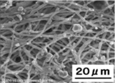
- FIG. 1 is a view showing an electron micrograph obtained in Example 3 before using the actual machine.
- FIG. 2 is an electron micrograph obtained after using the actual machine (surface) obtained in Example 3.
- FIG. 3 is a view showing an electron micrograph of the actual machine obtained in Example 3 after use (back side).
- the air filter for a CVD apparatus has, as an essential component, a polytetrafluoroethylene fiber (a) (PTFE) having an average fiber diameter of 10 nm to 50 ⁇ m.
- PTFE polytetrafluoroethylene fiber
- a filter medium layer (a) comprising fibers (a)), and a support layer (b) is laminated on one side or both sides of the filter medium layer (a) as necessary, as will be described later. Also good.
- the air filter of the present invention is in a state where the source gas and / or the exhaust gas can be filtered into a CVD (chemical vapor deposition) apparatus (specifically, the source gas supply port and / or the exhaust gas discharge port of the apparatus). And collect the particles (dust, dust) contained in the raw material gas and / or exhaust gas by filtering the raw material gas supplied into the device and / or the exhaust gas exhausted from inside the device ( Used to capture).
- the air filter of the present invention exhibits excellent air filter performance such as high heat resistance and high radical resistance (plasma resistance) as well as well-balanced air filter performance such as low pressure loss and high particle capture rate.
- CVD apparatus can be used for various types of CVD apparatuses regardless of the type of deposition and the mechanism of vapor deposition on the substrate.
- the CVD apparatus include a thermal CVD apparatus, a plasma CVD apparatus, a photo CVD apparatus, and a MOCVD (metalorgano-CVD) apparatus.
- the average fiber diameter of the PTFE fiber (a) is 10 nm to 50 ⁇ m, preferably 100 nm to 5000 nm.
- the pressure loss can be reduced and the air trapping performance can be improved, for example, the particle capture rate can be improved.
- the average fiber diameter of the PTFE fiber (a) is a region that is randomly observed by a scanning electron microscope (SEM) for the PTFE fiber (a) to be measured, and this region is then observed by SEM. (Magnification: 10,000 times) 10 PTFE fibers (a) were selected at random, the fiber diameters of the 10 selected PTFE fibers (a) were measured, and the obtained 10 fiber diameter values. Is an arithmetic average value calculated based on SEM.
- the PTFE fiber (a) when the PTFE fiber (a) is obtained by an electrospinning method, the PTFE concentration in the spinning solution, the atmospheric humidity during production, the tip diameter of the spinning nozzle, the applied voltage, the voltage density, etc. are appropriately adjusted. By doing so, PTFE fiber (a) having a desired average fiber diameter can be obtained.
- the electrospinning method the PTFE fiber (a) is obtained by using a spinning solution having a low PTFE concentration, lowering the atmospheric humidity, reducing the tip diameter of the spinning nozzle, increasing the applied voltage, or increasing the voltage density. The average fiber diameter tends to be small.
- PTFE fiber (a) is a fiber containing PTFE in a content of usually 95 to 100% by weight, preferably 99 to 100% by weight, more preferably 100% by weight.
- the air filter for a CVD apparatus according to the present invention can exhibit plasma resistance (radical resistance), heat resistance (particularly low heat shrinkage), and the like due to the characteristics of the PTFE fiber (a).
- the method for producing PTFE fiber (a) is not particularly limited as long as it is a method for producing PTFE fiber having an average fiber diameter in the above range, but is obtained by electrospinning (electrostatic spinning) method. Is preferred.
- the electrospinning method can easily obtain the PTFE fiber (a) having an average fiber diameter in the above range, and when the PTFE fiber (a) obtained by such a method is used for the air filter in the present invention, An air filter having a high particle trapping rate, low pressure loss, and high durability against heat, radicals and harmful substances can be realized.
- electrospinning method for example, from the spinning solution containing the above-mentioned PTFE and a solvent, and optionally additives (fiber forming agent, ionic surfactant, viscosity modifier, etc.), for example, US 2010/0193999 A1.
- a known electrospinning method such as the method described in Japanese Patent Publication No. 1993-2011 can be used.
- the porosity (porosity) of the filter medium layer (a) is preferably 0.60 to 0.95 from the viewpoint of securing a fluid flow path for preventing an increase in pressure loss and securing the filter medium strength. More preferably, it is 0.70 to 0.90.
- the basis weight of the filter medium layer (a) depends on the fiber diameter of the PTFE fiber, it is preferably 1 to 200 g / m 2 from the viewpoint of achieving both high particle capturing performance and low pressure loss and ensuring the filter medium strength. More preferably, it is 10 to 100 g / m 2 .
- the thickness of the filter medium layer (a) depends on the fiber diameter of the PTFE fiber, it is preferably 5 ⁇ m to 200 ⁇ m from the viewpoint of achieving both high particle capturing performance and low pressure loss.
- the porosity, basis weight, and thickness in the filter medium layer (a) are increased by increasing the spinning time or increasing the number of spinning nozzles when preparing the PTFE fiber (a) using the electrospinning method. Tend to.
- the manufacturing method of the air filter for CVD apparatus which concerns on this invention is not specifically limited,
- the process of manufacturing PTFE fiber (a) by the above-mentioned electrospinning method, and said PTFE fiber (a) in a sheet form It includes a step of accumulating to form an air filter.
- the filter medium layer (a) may be formed by collecting the PTFE fibers (a) in a sheet shape and forming them). Good).
- the air filter according to the present invention may be a filter medium layer (a) that is not laminated with a support layer (b) or the like (single-layer air filter), and may further include a filter medium layer.
- the support layer (b) or the like laminated air filter
- the laminated air filter includes, for example, a step of producing PTFE fibers (a) having a specific average fiber diameter as described above, and PTFE fibers (a) on at least one surface of the support layer (b). It can produce by implementing the process of accumulating in a sheet form and forming a filter medium layer (a). These two steps may be performed separately or simultaneously (that is, PTFE fibers (a) are accumulated in a sheet form on at least one surface of the support layer (b) while being produced).
- the filter medium layer (a) may be formed).
- a support body layer (b) the conventionally well-known support body layer in an air filter can be used, for example, the mesh comprised from iron, copper, stainless steel etc., for example, glass fiber, a cellulose fiber, polyolefin fiber, nylon Nonwoven fabrics composed of fibers, polyester fibers and the like can be mentioned.
- a support body layer (b) consists of a nonwoven fabric comprised from the mesh or glass fiber comprised from iron, copper, stainless steel, etc.
- the air filter of the present invention has at least one filter medium layer (c) made of a material different from the filter medium layer (a) in addition to the filter medium layer (a) comprising PTFE fibers (a). It may be.
- the air filter of the present invention may be composed of a filter medium layer (a) and one or more filter medium layers (c), and further laminated with one or more support layers (b). It may be a thing. In order to prevent clogging of the filter medium layer, it is preferable to collect dust for each particle diameter by a plurality of filter medium layers from the viewpoint of maintaining long-term performance of the air filter.
- the filter medium layer (c) is preferably metallic from the viewpoint of durability, and is a powder filter medium made of a sintered metal powder, a mesh filter medium made of a sintered metal wire mesh, a wool and a nonwoven cloth made of metal fibers. Conventionally known materials such as filter media can be used.
- the air filter of the present invention may be subjected to conventionally known processing within a range not impairing its performance, for example, may be subjected to pleating.
- PTFE fiber (a) 1 consisting only of PTFE was produced by an existing electrospinning method. The properties of the produced PTFE fiber (a) 1 were measured or evaluated based on the following “measurement method / evaluation criteria”. The obtained results are shown in Table 1.
- PTFE fiber (a) 1 was deposited (superposed) to produce a filter medium layer (a) 1 (length 10 cm, width 10 cm).
- the characteristics of the produced filter medium layer (a) 1 were measured or evaluated based on the following “measurement method / evaluation criteria”. The obtained results are shown in Table 1.
- Thickness of the filter medium layer (a) 1 The thickness of the filter medium layer (a) 1 was measured by LITEMATAC VL-50 (manufactured by Mitutoyo Corporation).
- the basis weight (g / m 2 ) of the filter medium layer (a) 1 of the filter medium layer (a) 1 was measured according to JIS L 1906 (2000).
- the porosity filter medium layer (a) 1 was cut into a 4 cm square (4 cm long ⁇ 4 cm wide) to prepare a test piece 1, and the weight (g) of the test piece 1 was measured. Then, by using the thickness measured in "2. Filter layer (a) thickness of 1" to calculate the volume above the test piece 1 (cm 3), further, the calculated volume (cm 3 ) And the weight (g) of the test piece 1, the density (g / cm 3 ) was calculated. The porosity was calculated based on the following formula (I) using the calculated density (g / cm 3 ).
- Average flow diameter and average flow diameter pressure Based on ASTM E1294-89 half dry method, average flow diameter and average flow diameter pressure were measured using Galwick (15.9 dyn / cm) as the immersion liquid.
- PTFE fiber (a) 1 was produced in the same manner as in Example 1, and then PTFE fiber (a) 1 was deposited (superposed) to filter medium layer (a) 2 (length 10 cm, width 10 cm, thickness 20 ⁇ m, A porosity of 0.76) was produced. The thickness and the porosity of the filter medium layer (a) 2 were measured in the same manner as in Example 1. The filter medium layer (a) 2 was cut into a size of 40 mm (A) length and 40 mm (B) width to prepare a sample. The prepared sample was left to stand for 30 minutes in an electric furnace (constant temperature dryer DRA430DA (manufactured by Advantech Toyo Co., Ltd.)) maintained at 260 ° C.
- an electric furnace constant temperature dryer DRA430DA (manufactured by Advantech Toyo Co., Ltd.)
- Example 3 The PTFE fiber (a) 1 produced in Example 1 was deposited (superposed) to produce a filter medium layer (a) 3 (length 20 cm, width 20 cm, thickness 59.5 ⁇ m). The thickness of the filter medium layer (a) 3 was measured in the same manner as in Example 1.
- an air filter (a) is manufactured by sequentially laminating a filter medium layer (a) 3, a stainless steel mesh as the support layer (b), and steel wool as the filter medium layer (c).
- a filter medium layer (a) 3 a stainless steel mesh as the support layer (b), and steel wool as the filter medium layer (c).
- the filter medium layer (c) of the air filter (a) was installed inside the CVD apparatus so that the filter medium layer (c) functions as a pre-filter (that is, the filter medium layer (a) 3 is outside the CVD apparatus). Installed).
- the actual machine operation was performed for 30 days, and the exhaust gas was passed through the air filter (a) when exhaust gas was discharged from the inside of the CVD apparatus to the outside.
- the air filter (a) was exposed to radical substances such as SiH 3 and SiH 2 contained in the exhaust gas under a high temperature condition of 200 ° C. with the exhaust gas.
- the filter medium layer (a) 3 is taken out, and the front surface (exhaust gas inlet side (inside the CVD apparatus)) and back surface (exhaust gas outlet surface (outside of the CVD apparatus)) of the filter medium layer (a) 3 are removed. Then, it was subjected to SEM observation (apparatus: S-3400N (manufactured by Hitachi High-Technologies Corporation), magnification: 2000 times) to obtain an electron micrograph.
- the filter medium layer (a) 3 before being incorporated into the CVD apparatus was subjected to SEM observation under the same conditions to obtain an electron micrograph. The obtained electron micrographs are shown in FIGS.
- the average flow diameter ( ⁇ m) and the average flow diameter were the same as in Example 1 except that the filter medium layer (a) 3 taken out after the actual machine operation was used instead of the filter medium layer (a) 1. Pressure (psi) was measured. The results are shown in Table 5.
- FIGS. 1 to 3 SEM photograph before operation of the actual machine (“before use of actual machine”) (FIG. 1), SEM photograph after operation of the actual machine (“after use of actual machine (surface)” (FIG. 2) and “actual machine” Comparing “after use (back surface)” (FIG. 3)), it can be seen that the shape of the PTFE fiber (a) 1 constituting the filter medium layer (a) 3 is not changed at all.
- the filter medium layer (a) 3 has a function of capturing particles in the exhaust gas discharged from the inside of the CVD apparatus to the outside.
- the filter medium layer (a) 3 has durability such as radical resistance and heat resistance required for an air filter for a CVD apparatus.
Abstract
[Problem] To provide an air filter for a CVD apparatus achieving filter performance with good balance between low pressure loss and high particle capture rate, and also having the preferred characteristics for use as an air filter for a CVD apparatus, such as excellent heat resistance and plasma resistance. [Solution] The air filter for a CVD apparatus of the present invention is characterized in having a filtering layer (a) including a PTFE fiber (a), the average fiber diameter of the PTFE fiber (a) being 10 nm to 50 µm.
Description
本発明は、CVD装置に用いられるエアフィルター(CVD装置用エアフィルター)およびそれを有するCVD装置に関する。
The present invention relates to an air filter used in a CVD apparatus (air filter for CVD apparatus) and a CVD apparatus having the same.
エアフィルターは、空気や原料ガスまたは排気ガスに含まれる微細な粒子を捕集(捕捉)するために用いられ、粒子捕捉率が高いこと(粒子を高い効率で捕集できること)や、圧力損失が低いことが求められる。エアフィルターを構成する材料も、用途に応じて多岐にわたっている。
The air filter is used to collect (capture) fine particles contained in air, source gas or exhaust gas, and has a high particle capture rate (capability of collecting particles with high efficiency) and pressure loss. Low is required. The materials that make up the air filter also vary widely depending on the application.
エアフィルターを構成する材料として、ポリテトラフルオロエチレン(PTFE)等のフッ素樹脂が知られている。フッ素樹脂は、優れた特性(耐薬品性、耐プラズマ性、耐熱性等)を有するために、フッ素樹脂製エアフィルターは、幅広い用途で使用されている。
Fluorine resin such as polytetrafluoroethylene (PTFE) is known as a material constituting the air filter. Since fluororesins have excellent properties (chemical resistance, plasma resistance, heat resistance, etc.), fluororesin air filters are used in a wide range of applications.
特許文献1では、複合フィルター媒体とフレームとを含むタービン空気吸入口フィルターが開示され、かかる複合フィルター媒体は、多孔質ポリテトラフルオロエチレン(延伸PTFE)を含む膜フィルター層とデプスフィルター媒体層とを含んでなる。
Patent Document 1 discloses a turbine air inlet filter including a composite filter medium and a frame. The composite filter medium includes a membrane filter layer containing porous polytetrafluoroethylene (expanded PTFE) and a depth filter medium layer. Comprising.
特許文献2では、特定条件で未焼成のPTFEを延伸して得られたPTFE多孔質膜(延伸PTFE)を備えるフィルター濾材が開示されている。
Patent Document 2 discloses a filter medium including a PTFE porous membrane (stretched PTFE) obtained by stretching unsintered PTFE under specific conditions.
これらの延伸PTFE製フィルターは、他のポリマー材料で構成されたフィルターに比べて、耐プラズマ性等は優れているものの、依然として、熱収縮などが発生するため、耐熱性等の点で、改善の余地があった。
Although these expanded PTFE filters are superior in plasma resistance and the like compared to filters made of other polymer materials, heat shrinkage and the like still occur. There was room.
一方で、特許文献3では、PTFE粉末をマトリックス(例:ビスコース)中に分散して水性ディスパージョンを調製し、水性ディスパージョンを凝固浴中に吐出して紡糸して未延伸PTFE系繊維シートを得、未延伸PTFE系繊維シートを加熱焼結し、少なくとも縦方向または横方向に延伸して製造された、フィルター用途に用いられるフッ素繊維薄葉シートが開示されている。
On the other hand, in Patent Document 3, an PTFE powder is dispersed in a matrix (e.g., viscose) to prepare an aqueous dispersion, and the aqueous dispersion is discharged into a coagulation bath and spun to produce an unstretched PTFE fiber sheet. A fluorine fiber thin sheet used for filter applications is disclosed, which is produced by heating and sintering an unstretched PTFE fiber sheet and stretching it at least in the longitudinal direction or the transverse direction.
また、特許文献4では、フッ素系繊維の抄紙原料を、金網抄き型を用いた湿式抄紙法により脱水、乾燥して成形原体を形成し、成形原体を、加熱処理後の該成形原体の内壁に密着可能な型に載置し、フッ素系繊維の融点以上に加熱して繊維間を融着することにより、予備成形体を作成したのち、さらに予備成形体の形状に対応した雌雄の型に該予備成形体を嵌入し熱圧成形して得られた、フィルター用途に用いられるフッ素繊維成形体が開示されている。
Further, in Patent Document 4, a raw material for paper making of a fluoro fiber is dehydrated and dried by a wet paper making method using a wire netting die to form a forming raw material, and the forming raw material is subjected to the heat treatment after the forming raw material. A male and female corresponding to the shape of the preform after it was placed on a mold that can be in close contact with the inner wall of the body and heated between the melting points of the fluorinated fibers to fuse the fibers together. There is disclosed a fluorine fiber molded article used for a filter, which is obtained by inserting the preform into a mold and hot pressing.
このようなフッ素繊維からなるフィルターは、圧力損失と粒子捕捉性とをバランスよく両立できず、依然として、フィルター性能について改善の余地があった。
Such a filter made of a fluorine fiber cannot balance pressure loss and particle trapping in a well-balanced manner, and there is still room for improvement in filter performance.
ところで、化学蒸着(CVD:Chemical Vapor Deposition)法は、基板物質上に、目的とする薄膜の成分を含む原料ガスをCVD装置内に供給し、基板表面や気相での化学反応により薄膜を堆積する方法である。たとえば、切削工具の表面処理や半導体素子の製造工程において一般的に使用されている。また、CVDの種類は、薄膜の形成メカニズムに応じて熱CVDやプラズマCVD等、多岐にわたっている。
By the way, the chemical vapor deposition (CVD: Chemical Vapor Deposition) method supplies a raw material gas containing the desired thin film components onto the substrate material into the CVD apparatus, and deposits the thin film by chemical reaction on the substrate surface or in the gas phase. It is a method to do. For example, it is generally used in the surface treatment of cutting tools and the manufacturing process of semiconductor elements. Further, the types of CVD are various such as thermal CVD and plasma CVD according to the formation mechanism of the thin film.
CVD装置から排出される排気ガス中には、SiO2、SiH4、SiCl4を初めとするさまざまな汚染物質が含まれるため、大気中へ放出される前にフィルター等により除去することが求められる。そのためCVD装置の排気口に設置されるフィルターは、高い粒子捕捉率を有することが求められる。更に、CVD装置内部は、高温雰囲気であったり(たとえば、熱CVD)、原料ガスがプラズマ状態に励起されていたりする(たとえば、プラズマCVD)など、過酷な条件になるために、CVD装置に用いられるフィルターには、耐熱性や耐プラズマ性(耐ラジカル性)も求められる。
Since the exhaust gas discharged from the CVD apparatus contains various pollutants such as SiO 2 , SiH 4 , and SiCl 4 , it is required to be removed by a filter or the like before being released into the atmosphere. . Therefore, the filter installed at the exhaust port of the CVD apparatus is required to have a high particle capture rate. Furthermore, since the inside of the CVD apparatus is in a high temperature atmosphere (for example, thermal CVD) or the source gas is excited to a plasma state (for example, plasma CVD), it is used in the CVD apparatus. Such a filter is also required to have heat resistance and plasma resistance (radical resistance).
本発明は、圧力損失が低く、粒子の捕捉率が高いといった、バランスよいフィルター性能を発揮するとともに、耐熱性や耐プラズマ性に優れる等、CVD装置用エアフィルターに用いられるのに好適な特性を有するCVD装置用エアフィルターおよびそれを有するCVD装置を提供することを目的としている。
The present invention exhibits characteristics suitable for use in an air filter for a CVD apparatus, such as a well-balanced filter performance such as low pressure loss and high particle capture rate, and excellent heat resistance and plasma resistance. An object of the present invention is to provide an air filter for a CVD apparatus and a CVD apparatus having the same.
本発明者らは鋭意研究した結果、エアフィルターの材料として、特定の平均繊維径を有するPTFE繊維を含んでなる濾材層を用いると、圧力損失が低く、粒子の捕捉率が高いといったバランスよいフィルター性能を発揮すること、および、耐熱性や耐プラズマ性に優れることを見出した。そして、本発明者らは、このような、CVD装置用エアフィルターとして好適な特性を発揮し得ることに基づいて、本発明を完成させた。
As a result of intensive studies, the present inventors have found that when a filter medium layer containing PTFE fibers having a specific average fiber diameter is used as an air filter material, the pressure loss is low and the particle trapping rate is high. It has been found that it exhibits performance and is excellent in heat resistance and plasma resistance. And the present inventors completed this invention based on being able to exhibit the characteristic suitable as such an air filter for CVD apparatuses.
すなわち、本発明の要旨は以下の通りである。
That is, the gist of the present invention is as follows.
[1] PTFE繊維(a)を含んでなる濾材層(a)を有するCVD装置用エアフィルターであって、前記PTFE繊維(a)の平均繊維径が、10nm~50μmであることを特徴とする、CVD装置用エアフィルター。
[1] An air filter for a CVD apparatus having a filter medium layer (a) containing PTFE fiber (a), wherein the PTFE fiber (a) has an average fiber diameter of 10 nm to 50 μm. Air filter for CVD equipment.
[2] 濾材層(a)の厚さが、5μm~200μmであることを特徴とする、[1]に記載のCVD装置用エアフィルター。
[2] The CVD apparatus air filter according to [1], wherein the thickness of the filter medium layer (a) is 5 μm to 200 μm.
[3] 濾材層(a)の空隙率が、0.60~0.95であることを特徴とする、[1]または[2]に記載のCVD装置用エアフィルター。
[3] The air filter for a CVD apparatus according to [1] or [2], wherein the porosity of the filter medium layer (a) is 0.60 to 0.95.
[4] 前記PTFE繊維(a)が、電界紡糸法により得られたものであることを特徴とする、[1]~[3]の何れか一項に記載のCVD装置用エアフィルター。
[4] The CVD device air filter according to any one of [1] to [3], wherein the PTFE fiber (a) is obtained by an electrospinning method.
[5] 濾材層(a)の片面または両面に、支持体層(b)が積層されてなることを特徴とする、[1]~[4]の何れか一項に記載のCVD装置用エアフィルター。
[5] The CVD apparatus air according to any one of [1] to [4], wherein the support layer (b) is laminated on one side or both sides of the filter medium layer (a). filter.
[6] [1]~[5]の何れか一項に記載のCVD装置用エアフィルターが、原料ガス供給口および/またはガス排気口に設置されていることを特徴とする、CVD装置。
[6] A CVD apparatus, wherein the air filter for a CVD apparatus according to any one of [1] to [5] is installed at a source gas supply port and / or a gas exhaust port.
本発明に係るCVD装置用エアフィルターによれば、高い耐熱性および高い耐ラジカル性(耐プラズマ性)とともに、低い圧力損失および高い粒子捕捉率を有するといったバランスの良い優れたエアフィルター性能が発揮される。
According to the air filter for a CVD apparatus according to the present invention, excellent air filter performance with a good balance such as having a high pressure resistance and a high particle trapping rate as well as high heat resistance and high radical resistance (plasma resistance) is exhibited. The
以下、本発明をより詳細に説明する。
Hereinafter, the present invention will be described in more detail.
本発明に係るCVD装置用エアフィルター(以後、単に「エアフィルター」と称する場合もある。)は、必須構成要件として、10nm~50μmの平均繊維径を有するポリテトラフルオロエチレン繊維(a)(PTFE繊維(a))を含んでなる濾材層(a)を有し、必要に応じて、後述するように、濾材層(a)の片面または両面に、支持体層(b)が積層されていてもよい。
The air filter for a CVD apparatus according to the present invention (hereinafter sometimes simply referred to as “air filter”) has, as an essential component, a polytetrafluoroethylene fiber (a) (PTFE) having an average fiber diameter of 10 nm to 50 μm. A filter medium layer (a) comprising fibers (a)), and a support layer (b) is laminated on one side or both sides of the filter medium layer (a) as necessary, as will be described later. Also good.
本発明のエアフィルターは、CVD(化学蒸着)装置に、(具体的には、該装置の原料ガス供給口および/または排気ガス排出口に、原料ガスおよび/または排気ガスを濾過できるような状態で)設置して、装置内に供給される原料ガスおよび/または装置内から排出される排気ガスを濾過して、原料ガスおよび/または排気ガスに含まれる粒子(塵、ダスト)を捕集(捕捉)するために用いられる。そして、本発明のエアフィルターは、高い耐熱性および高い耐ラジカル性(耐プラズマ性)とともに、低い圧力損失および高い粒子捕捉率といったバランスの良い優れたエアフィルター性能が発揮されるために、原料ガスの種類、基板への蒸着メカニズムを問わず、様々なタイプのCVD装置に使用することができる。なお、CVD装置としては、熱CVD装置、プラズマCVD装置、光CVD装置、MOCVD(metalorganoic CVD)装置が挙げられる。
The air filter of the present invention is in a state where the source gas and / or the exhaust gas can be filtered into a CVD (chemical vapor deposition) apparatus (specifically, the source gas supply port and / or the exhaust gas discharge port of the apparatus). And collect the particles (dust, dust) contained in the raw material gas and / or exhaust gas by filtering the raw material gas supplied into the device and / or the exhaust gas exhausted from inside the device ( Used to capture). The air filter of the present invention exhibits excellent air filter performance such as high heat resistance and high radical resistance (plasma resistance) as well as well-balanced air filter performance such as low pressure loss and high particle capture rate. It can be used for various types of CVD apparatuses regardless of the type of deposition and the mechanism of vapor deposition on the substrate. Examples of the CVD apparatus include a thermal CVD apparatus, a plasma CVD apparatus, a photo CVD apparatus, and a MOCVD (metalorgano-CVD) apparatus.
本発明のエアフィルターにおいて、PTFE繊維(a)の平均繊維径は、10nm~50μmであり、好ましくは、100nm~5000nmである。PTFE繊維(a)の平均繊維径がこのような範囲にあることで、圧力損失が低減されるとともに、粒子捕捉率が向上するなど、エアフィルター性能を向上させることができる。
In the air filter of the present invention, the average fiber diameter of the PTFE fiber (a) is 10 nm to 50 μm, preferably 100 nm to 5000 nm. When the average fiber diameter of the PTFE fiber (a) is in such a range, the pressure loss can be reduced and the air trapping performance can be improved, for example, the particle capture rate can be improved.
ここで、PTFE繊維(a)の平均繊維径とは、測定対象となるPTFE繊維(a)について、無作為に走査型電子顕微鏡(SEM)観察される領域を選び、次いで、この領域をSEM観察(倍率:10000倍)して無作為に10本のPTFE繊維(a)を選び、選ばれた10本のPTFE繊維(a)の繊維径を測定し、得られた10本の繊維径の値に基づいて算出される算術平均値である。
Here, the average fiber diameter of the PTFE fiber (a) is a region that is randomly observed by a scanning electron microscope (SEM) for the PTFE fiber (a) to be measured, and this region is then observed by SEM. (Magnification: 10,000 times) 10 PTFE fibers (a) were selected at random, the fiber diameters of the 10 selected PTFE fibers (a) were measured, and the obtained 10 fiber diameter values. Is an arithmetic average value calculated based on
後述するように、PTFE繊維(a)が電界紡糸法によって得られるものである場合、紡糸液中のPTFE濃度、製造時の雰囲気湿度、紡糸ノズルの先端径、印加電圧、電圧密度などを適宜調整することで、所望の平均繊維径を有するPTFE繊維(a)を得ることができる。なお、電界紡糸法において、PTFE濃度が低い紡糸液を用いる、雰囲気湿度を下げる、紡糸ノズルの先端径を小さくする、印加電圧を大きくする、あるいは電圧密度を大きくするなどにより、PTFE繊維(a)の平均繊維径は小さくなる傾向にある。
As will be described later, when the PTFE fiber (a) is obtained by an electrospinning method, the PTFE concentration in the spinning solution, the atmospheric humidity during production, the tip diameter of the spinning nozzle, the applied voltage, the voltage density, etc. are appropriately adjusted. By doing so, PTFE fiber (a) having a desired average fiber diameter can be obtained. In the electrospinning method, the PTFE fiber (a) is obtained by using a spinning solution having a low PTFE concentration, lowering the atmospheric humidity, reducing the tip diameter of the spinning nozzle, increasing the applied voltage, or increasing the voltage density. The average fiber diameter tends to be small.
「PTFE繊維(a)」とは、PTFEを、通常95~100重量%、好ましくは99~100重量%、より好ましくは100重量%の含有量で含む繊維である。本発明に係るCVD装置用エアフィルターは、PTFE繊維(a)の特性に起因して、耐プラズマ性(耐ラジカル性)や耐熱性(特に、低い熱収縮性)などを発揮することができる。
“PTFE fiber (a)” is a fiber containing PTFE in a content of usually 95 to 100% by weight, preferably 99 to 100% by weight, more preferably 100% by weight. The air filter for a CVD apparatus according to the present invention can exhibit plasma resistance (radical resistance), heat resistance (particularly low heat shrinkage), and the like due to the characteristics of the PTFE fiber (a).
PTFE繊維(a)の製造方法は、上記範囲の平均繊維径を有するPTFE繊維を製造する方法である限り、特に限定されるものではないが、電界紡糸(静電紡糸)法により得られたものが好ましい。電界紡糸法は、上記範囲の平均繊維径を有するPTFE繊維(a)を容易に得ることができ、本発明におけるエアフィルターに、このような方法で得られたPTFE繊維(a)を用いると、高い粒子捕捉率、低い圧力損失、熱やラジカルや有害物質への高い耐久性を有するエアフィルターを実現できるようになる。
The method for producing PTFE fiber (a) is not particularly limited as long as it is a method for producing PTFE fiber having an average fiber diameter in the above range, but is obtained by electrospinning (electrostatic spinning) method. Is preferred. The electrospinning method can easily obtain the PTFE fiber (a) having an average fiber diameter in the above range, and when the PTFE fiber (a) obtained by such a method is used for the air filter in the present invention, An air filter having a high particle trapping rate, low pressure loss, and high durability against heat, radicals and harmful substances can be realized.
上記電界紡糸法として、上述したPTFEおよび溶媒、さらには必要に応じて添加剤(繊維形成剤、イオン性界面活性剤、粘度調整剤等)を含む紡糸液から、例えば米国特開2010/0193999 A1号公報に記載の方法など公知の電界紡糸法を用いることができる。
As the electrospinning method, for example, from the spinning solution containing the above-mentioned PTFE and a solvent, and optionally additives (fiber forming agent, ionic surfactant, viscosity modifier, etc.), for example, US 2010/0193999 A1. A known electrospinning method such as the method described in Japanese Patent Publication No. 1993-2011 can be used.
濾材層(a)の空隙率(多孔度)は、圧力損失の増加を防ぐための流体流路の確保、ろ材強度の確保という観点からは、好ましくは、0.60~0.95であり、より好ましくは0.70~0.90である。
The porosity (porosity) of the filter medium layer (a) is preferably 0.60 to 0.95 from the viewpoint of securing a fluid flow path for preventing an increase in pressure loss and securing the filter medium strength. More preferably, it is 0.70 to 0.90.
濾材層(a)の目付は、PTFE繊維の繊維径にもよるが、高粒子捕捉性能と低圧力損失との両立、濾材強度の確保という観点からは、好ましくは1~200g/m2であり、より好ましくは10~100g/m2である。
Although the basis weight of the filter medium layer (a) depends on the fiber diameter of the PTFE fiber, it is preferably 1 to 200 g / m 2 from the viewpoint of achieving both high particle capturing performance and low pressure loss and ensuring the filter medium strength. More preferably, it is 10 to 100 g / m 2 .
濾材層(a)の厚さは、PTFE繊維の繊維径にもよるが、高粒子捕捉性能と低圧力損失との両立という観点からは、好ましくは5μm~200μmである。
Although the thickness of the filter medium layer (a) depends on the fiber diameter of the PTFE fiber, it is preferably 5 μm to 200 μm from the viewpoint of achieving both high particle capturing performance and low pressure loss.
なお、濾材層(a)における、空隙率、目付および厚さは、電界紡糸法を用いてPTFE繊維(a)を調製する際に、紡糸時間を長くする、紡糸ノズル数を増やすなどにより、増大する傾向にある。
The porosity, basis weight, and thickness in the filter medium layer (a) are increased by increasing the spinning time or increasing the number of spinning nozzles when preparing the PTFE fiber (a) using the electrospinning method. Tend to.
本発明に係るCVD装置用エアフィルターの製造方法は、特に限定されないが、たとえば、上述したような電界紡糸法によりPTFE繊維(a)を製造する工程、および前記PTFE繊維(a)をシート状に集積してエアフィルターを形成する工程を含むものである。
Although the manufacturing method of the air filter for CVD apparatus which concerns on this invention is not specifically limited, For example, the process of manufacturing PTFE fiber (a) by the above-mentioned electrospinning method, and said PTFE fiber (a) in a sheet form It includes a step of accumulating to form an air filter.
なお、これら2つの工程は、別途独立に行ってもよく、同時に行ってもよい(すなわち、PTFE繊維(a)を製造しつつシート状に集積して、濾材層(a)を形成してもよい)。
Note that these two steps may be performed separately or simultaneously (that is, the filter medium layer (a) may be formed by collecting the PTFE fibers (a) in a sheet shape and forming them). Good).
また、本発明に係るエアフィルターは、支持体層(b)などが積層されていない、濾材層(a)のみからなるもの(単層型エアフィルター)であってもよいし、さらに、濾材層(a)の片面または両面に支持体層(b)等が積層されてなるもの(積層型エアフィルター)であってもよい。
In addition, the air filter according to the present invention may be a filter medium layer (a) that is not laminated with a support layer (b) or the like (single-layer air filter), and may further include a filter medium layer. The support layer (b) or the like (laminated air filter) may be laminated on one or both sides of (a).
なお、上記積層エアフィルターは、たとえば、上記のように特定の平均繊維径を有するPTFE繊維(a)を作製する工程と、支持体層(b)の少なくとも一方の表面にPTFE繊維(a)をシート状に集積して濾材層(a)を形成する工程とを実施することで作製できる。これら2つの工程は、別途独立に行ってもよく、同時に行ってもよい(すなわち、PTFE繊維(a)を、製造しつつ支持体層(b)の少なくとも一方の表面にシート状に集積して、濾材層(a)を形成してもよい)。
The laminated air filter includes, for example, a step of producing PTFE fibers (a) having a specific average fiber diameter as described above, and PTFE fibers (a) on at least one surface of the support layer (b). It can produce by implementing the process of accumulating in a sheet form and forming a filter medium layer (a). These two steps may be performed separately or simultaneously (that is, PTFE fibers (a) are accumulated in a sheet form on at least one surface of the support layer (b) while being produced). The filter medium layer (a) may be formed).
また、支持体層(b)としては、エアフィルターにおける従来公知の支持体層を用いることができ、たとえば鉄、銅、ステンレス等から構成されるメッシュ、たとえばガラス繊維、セルロース繊維、ポリオレフィン繊維、ナイロン繊維、ポリエステル繊維などから構成される不織布などが挙げられる。中でも、耐久性の観点からは、支持体層(b)は鉄、銅、ステンレス等から構成されるメッシュまたはガラス繊維から構成される不織布からなることが好ましい。
Moreover, as a support body layer (b), the conventionally well-known support body layer in an air filter can be used, for example, the mesh comprised from iron, copper, stainless steel etc., for example, glass fiber, a cellulose fiber, polyolefin fiber, nylon Nonwoven fabrics composed of fibers, polyester fibers and the like can be mentioned. Especially, from a viewpoint of durability, it is preferable that a support body layer (b) consists of a nonwoven fabric comprised from the mesh or glass fiber comprised from iron, copper, stainless steel, etc.
また、本発明のエアフィルターは、PTFE繊維(a)を含んでなる濾材層(a)の他に、前記濾材層(a)とは材質の異なる1つ以上の濾材層(c)を有していてもよい。この場合、本発明のエアフィルターは濾材層(a)と1つ以上の濾材層(c)からなるものであってもよいし、さらに1つ以上の支持体層(b)を積層してなるものであってもよい。濾材層の目詰まりの防止につながるため、エアフィルターの長期性能保持の観点から、複数の濾材層により塵(ダスト)を粒径毎に捕集していくことが好ましい。
In addition, the air filter of the present invention has at least one filter medium layer (c) made of a material different from the filter medium layer (a) in addition to the filter medium layer (a) comprising PTFE fibers (a). It may be. In this case, the air filter of the present invention may be composed of a filter medium layer (a) and one or more filter medium layers (c), and further laminated with one or more support layers (b). It may be a thing. In order to prevent clogging of the filter medium layer, it is preferable to collect dust for each particle diameter by a plurality of filter medium layers from the viewpoint of maintaining long-term performance of the air filter.
濾材層(c)としては、耐久性の観点から金属性であることが好ましく、金属焼結粉末からなるパウダー状濾材、焼結金属金網からなるメッシュ状濾材、金属繊維からなるウール状及び不織布状濾材など従来公知のものを用いることができる。
The filter medium layer (c) is preferably metallic from the viewpoint of durability, and is a powder filter medium made of a sintered metal powder, a mesh filter medium made of a sintered metal wire mesh, a wool and a nonwoven cloth made of metal fibers. Conventionally known materials such as filter media can be used.
また、本発明のエアフィルターには、その性能を損なわない範囲で従来公知の加工が施されていてもよく、たとえばプリーツ加工が施されていてもよい。
In addition, the air filter of the present invention may be subjected to conventionally known processing within a range not impairing its performance, for example, may be subjected to pleating.
以下、本発明を実施例によりさらに詳細に説明するが、本発明はこれらの実施例により何ら限定されるものではない。
Hereinafter, the present invention will be described in more detail with reference to examples, but the present invention is not limited to these examples.
[実施例1]
既存の電界紡糸法によりPTFEのみからなるPTFE繊維(a)1を製造した。製造されたPTFE繊維(a)1の特性を、下記「測定方法・評価基準」に基づいて、測定または評価した。得られた結果を表1に示す。 [Example 1]
PTFE fiber (a) 1 consisting only of PTFE was produced by an existing electrospinning method. The properties of the produced PTFE fiber (a) 1 were measured or evaluated based on the following “measurement method / evaluation criteria”. The obtained results are shown in Table 1.
次いで、PTFE繊維(a)1を堆積して(重ね合わせて)濾材層(a)1(縦10cm、横10cm)を製造した。製造された濾材層(a)1の特性を、下記「測定方法・評価基準」に基づいて、測定または評価した。得られた結果を表1に示す。
Next, PTFE fiber (a) 1 was deposited (superposed) to produce a filter medium layer (a) 1 (length 10 cm, width 10 cm). The characteristics of the produced filter medium layer (a) 1 were measured or evaluated based on the following “measurement method / evaluation criteria”. The obtained results are shown in Table 1.
[測定方法・評価基準]
1.PTFE繊維(a)1の平均繊維径
PTFE繊維(a)1について、無作為にSEM観察の領域を選び、この領域をSEM観察(装置:S-3400N((株)日立ハイテクノロジーズ製)、倍率:10000倍)して無作為に10本のPTFE繊維(a)1を選び、これらのPTFE繊維(a)1の測定結果に基づいて、平均(算術平均)繊維径を算出した。 [Measurement method and evaluation criteria]
1. PTFE fiber (a) 1 average fiber diameter For PTFE fiber (a) 1, a region for SEM observation was randomly selected, and this region was subjected to SEM observation (device: S-3400N (manufactured by Hitachi High-Technologies Corporation)),magnification 10 times), 10 PTFE fibers (a) 1 were selected at random, and the average (arithmetic average) fiber diameter was calculated based on the measurement results of these PTFE fibers (a) 1.
1.PTFE繊維(a)1の平均繊維径
PTFE繊維(a)1について、無作為にSEM観察の領域を選び、この領域をSEM観察(装置:S-3400N((株)日立ハイテクノロジーズ製)、倍率:10000倍)して無作為に10本のPTFE繊維(a)1を選び、これらのPTFE繊維(a)1の測定結果に基づいて、平均(算術平均)繊維径を算出した。 [Measurement method and evaluation criteria]
1. PTFE fiber (a) 1 average fiber diameter For PTFE fiber (a) 1, a region for SEM observation was randomly selected, and this region was subjected to SEM observation (device: S-3400N (manufactured by Hitachi High-Technologies Corporation)),
2.濾材層(a)1の厚さ
濾材層(a)1の厚さを、LITEMATIC VL-50((株)ミツトヨ製)により測定した。 2. Thickness of the filter medium layer (a) 1 The thickness of the filter medium layer (a) 1 was measured by LITEMATAC VL-50 (manufactured by Mitutoyo Corporation).
濾材層(a)1の厚さを、LITEMATIC VL-50((株)ミツトヨ製)により測定した。 2. Thickness of the filter medium layer (a) 1 The thickness of the filter medium layer (a) 1 was measured by LITEMATAC VL-50 (manufactured by Mitutoyo Corporation).
3.濾材層(a)1の目付
濾材層(a)1の目付(g/m2)を、JIS L 1906(2000)に準じて測定した。 3. The basis weight (g / m 2 ) of the filter medium layer (a) 1 of the filter medium layer (a) 1 was measured according to JIS L 1906 (2000).
濾材層(a)1の目付(g/m2)を、JIS L 1906(2000)に準じて測定した。 3. The basis weight (g / m 2 ) of the filter medium layer (a) 1 of the filter medium layer (a) 1 was measured according to JIS L 1906 (2000).
4.空隙率
濾材層(a)1を4cm角(縦4cm×横4cm)に切り出して、試験片1を作成し、かかる試験片1の重量(g)を測定した。次いで、「2.濾材層(a)1の厚さ」の項で測定された厚さを用いて、上記試験片1の体積(cm3)を算出し、さらに、算出された体積(cm3)と試験片1の重量(g)とから密度(g/cm3)を算出した。算出された密度(g/cm3)を用いて、下記式(I)に基づいて空隙率を算出した。 4). The porosity filter medium layer (a) 1 was cut into a 4 cm square (4 cm long × 4 cm wide) to prepare a test piece 1, and the weight (g) of the test piece 1 was measured. Then, by using the thickness measured in "2. Filter layer (a) thickness of 1" to calculate the volume above the test piece 1 (cm 3), further, the calculated volume (cm 3 ) And the weight (g) of the test piece 1, the density (g / cm 3 ) was calculated. The porosity was calculated based on the following formula (I) using the calculated density (g / cm 3 ).
濾材層(a)1を4cm角(縦4cm×横4cm)に切り出して、試験片1を作成し、かかる試験片1の重量(g)を測定した。次いで、「2.濾材層(a)1の厚さ」の項で測定された厚さを用いて、上記試験片1の体積(cm3)を算出し、さらに、算出された体積(cm3)と試験片1の重量(g)とから密度(g/cm3)を算出した。算出された密度(g/cm3)を用いて、下記式(I)に基づいて空隙率を算出した。 4). The porosity filter medium layer (a) 1 was cut into a 4 cm square (4 cm long × 4 cm wide) to prepare a test piece 1, and the weight (g) of the test piece 1 was measured. Then, by using the thickness measured in "2. Filter layer (a) thickness of 1" to calculate the volume above the test piece 1 (cm 3), further, the calculated volume (cm 3 ) And the weight (g) of the test piece 1, the density (g / cm 3 ) was calculated. The porosity was calculated based on the following formula (I) using the calculated density (g / cm 3 ).

ASTM E1294-89のハーフドライ法に基づき、Galwick(15.9dyn/cm)を浸漬液として用いて平均流量径および平均流量径圧力を測定した。
縦軸が流量を、横軸が濾材層(a)1に供される圧力を示す、Galwick(浸漬液)に浸漬されていない濾材層(a)1の通気曲線(ドライカーブ)と、Galwick(浸漬液)に浸漬された濾材層(a)1の通気曲線(ウェットカーブ)とを作成した。さらに、ドライカーブの傾きを算出し、ドライカーブの1/2の値の傾きを有する曲線(ハーフドライカーブ)を作成した。
The aeration curve (dry curve) of the filter medium layer (a) 1 not immersed in Galwick (immersion liquid), the vertical axis indicates the flow rate, and the horizontal axis indicates the pressure applied to the filter medium layer (a) 1, and Galwick ( A ventilation curve (wet curve) of the filter medium layer (a) 1 immersed in the immersion liquid) was prepared. Further, the slope of the dry curve was calculated, and a curve (half dry curve) having a half of the value of the dry curve was created.
次いで、ウェットカーブとハーフドライカーブとの交点における圧力(平均流量径圧力)を求め、これを下記のWashburnの式に代入し、平均流量径dを算出した。
Next, the pressure at the intersection of the wet curve and the half dry curve (average flow diameter pressure) was determined, and this was substituted into the following Washburn equation to calculate the average flow diameter d.
d=4γcosθ/P
(式中、θは濾材層と浸漬液との接触角を、γ[N/m]は浸漬液の表面張力を、Pは平均流量径圧力を表す。)
6.粒子捕捉率および圧力損失
濾材層(a)1について、JIS B 9908に準じて、粒子捕捉率を測定した。この際、エアフィルターユニットの替わりに200mm×200mmの大きさに切り出された濾材層(a)1を用い、測定用粉塵として、表2に示されるような特定粒子径範囲を有する大気塵を用いた。粒子捕捉率の測定の際には、空気の流量を面速度5.3cm/sとした。また、この測定と共に、濾材層(a)1の上流側および下流側での圧力の差(すなわち、圧力損失)を微差圧計により測定した。この測定は、表3に示されるように空気の流量を変えて行った。 d = 4γ cos θ / P
(In the formula, θ represents the contact angle between the filter medium layer and the immersion liquid, γ [N / m] represents the surface tension of the immersion liquid, and P represents the average flow diameter pressure.)
6). For the particle trapping rate and the pressure loss filter medium layer (a) 1, the particle trapping rate was measured according to JIS B 9908. At this time, instead of the air filter unit, the filter medium layer (a) 1 cut into a size of 200 mm × 200 mm was used, and atmospheric dust having a specific particle diameter range as shown in Table 2 was used as measurement dust. It was. When measuring the particle capture rate, the air flow rate was set to a surface velocity of 5.3 cm / s. Further, along with this measurement, the pressure difference (that is, pressure loss) between the upstream side and the downstream side of the filter medium layer (a) 1 was measured with a fine differential pressure gauge. This measurement was performed by changing the air flow rate as shown in Table 3.


実施例1と同様にPTFE繊維(a)1を製造し、次いで、PTFE繊維(a)1を堆積して(重ね合わせて)濾材層(a)2(縦10cm、横10cm、厚さ20μm、空隙率0.76)を製造した。なお、濾材層(a)2の厚さおよび空隙率は、実施例1と同様に測定されたものである。この濾材層(a)2を縦40mm(A)、横40mm(B)の寸法に切り出してサンプルを作製した。作製されたサンプルを、枠など固定器具による固定をせずに260℃に保持された電気炉(定温乾燥器DRA430DA(アドバンテック東洋株式会社製))内に30分間静置した。その後電気炉より取り出し、室温まで空冷後、熱処理後の寸法として縦の長さ(a)および横の長さ(b)を測定した。熱処理前の縦の長さ(A)および横の長さ(B)と、熱処理後の縦の長さ(a)および横の長さ(b)の長さと下記式に基づいて、縦および横における収縮率(%)を算出した。結果を表4に示す
PTFE fiber (a) 1 was produced in the same manner as in Example 1, and then PTFE fiber (a) 1 was deposited (superposed) to filter medium layer (a) 2 (

実施例2において濾材層(a)2の代わりに延伸PTFE(縦40mm、横40mm、厚さ108μm、空隙率0.86:住友電気工業株式会社製ポアフロン(登録商標)メンブレン)を用いた以外は同様に、260℃での熱処理後の収縮率の評価を行なった。結果を表4に示す。
Except for using expanded PTFE (length 40 mm, width 40 mm, thickness 108 μm, porosity 0.86: Poaflon (registered trademark) membrane manufactured by Sumitomo Electric Industries, Ltd.) instead of the filter medium layer (a) 2 in Example 2. Similarly, the shrinkage rate after heat treatment at 260 ° C. was evaluated. The results are shown in Table 4.

[実施例3]
実施例1で製造されたPTFE繊維(a)1を堆積して(重ね合わせて)、濾材層(a)3(縦20cm、横20cm、厚さ59.5μm)を製造した。なお、濾材層(a)3の厚さは、実施例1と同様にして測定されたものである。 [Example 3]
The PTFE fiber (a) 1 produced in Example 1 was deposited (superposed) to produce a filter medium layer (a) 3 (length 20 cm, width 20 cm, thickness 59.5 μm). The thickness of the filter medium layer (a) 3 was measured in the same manner as in Example 1.
次に、濾材層(a)3、支持体層(b)としてステンレス製メッシュ、濾材層(c)としてスチールウールを順次積層することによりエアフィルター(a)を製造し、エアフィルター(a)を、シリコン膜形成用プラズマCVD装置のガス排気口に、従来のエアフィルターの代わりに組み込んだ。ここで、濾材層(c)がプレフィルターとして機能するように、エアフィルター(a)の濾材層(c)をCVD装置内部側に設置した(すなわち、濾材層(a)3はCVD装置外部側に設置されている)。
Next, an air filter (a) is manufactured by sequentially laminating a filter medium layer (a) 3, a stainless steel mesh as the support layer (b), and steel wool as the filter medium layer (c). Instead of the conventional air filter, it was incorporated in the gas exhaust port of the plasma CVD apparatus for forming a silicon film. Here, the filter medium layer (c) of the air filter (a) was installed inside the CVD apparatus so that the filter medium layer (c) functions as a pre-filter (that is, the filter medium layer (a) 3 is outside the CVD apparatus). Installed).
次いで、30日間の実機運転を行ない、排気ガスを、CVD装置内部から外部へ排出する際に、エアフィルター(a)を通過させた。ここで、エアフィルター(a)は、排気ガスによって200℃の高温条件下で、排気ガスに含まれるSiH3、SiH2等のラジカル物質に曝された。
Next, the actual machine operation was performed for 30 days, and the exhaust gas was passed through the air filter (a) when exhaust gas was discharged from the inside of the CVD apparatus to the outside. Here, the air filter (a) was exposed to radical substances such as SiH 3 and SiH 2 contained in the exhaust gas under a high temperature condition of 200 ° C. with the exhaust gas.
実機運転終了後、濾材層(a)3を取り出して、濾材層(a)3の表面(排気ガス入り口側(CVD装置内部側))及び裏面(排気ガス出口面(CVD装置外部側))を、SEM観察(装置:S-3400N((株)日立ハイテクノロジーズ製)、倍率:2000倍)に供して、電子顕微鏡写真を得た。なお、CVD装置に組み込む前の濾材層(a)3を、同様の条件でSEM観察に供して電子顕微鏡写真を得た。得られた各電子顕微鏡写真を図1~3に示す。
After the operation of the actual machine is completed, the filter medium layer (a) 3 is taken out, and the front surface (exhaust gas inlet side (inside the CVD apparatus)) and back surface (exhaust gas outlet surface (outside of the CVD apparatus)) of the filter medium layer (a) 3 are removed. Then, it was subjected to SEM observation (apparatus: S-3400N (manufactured by Hitachi High-Technologies Corporation), magnification: 2000 times) to obtain an electron micrograph. The filter medium layer (a) 3 before being incorporated into the CVD apparatus was subjected to SEM observation under the same conditions to obtain an electron micrograph. The obtained electron micrographs are shown in FIGS.
また、濾材層(a)1ではなく、実機運転終了後に取り出された濾材層(a)3を用いたことを除いては、実施例1と同様にして平均流量径(μm)および平均流量径圧力(psi)を測定した。結果を表5に示す。
Further, the average flow diameter (μm) and the average flow diameter were the same as in Example 1 except that the filter medium layer (a) 3 taken out after the actual machine operation was used instead of the filter medium layer (a) 1. Pressure (psi) was measured. The results are shown in Table 5.

また、図2の「実機使用後(表面)」に示されるように、濾材層(a)3の表面に粒子状の物質が捕捉されていることが分かる。すなわち、濾材層(a)3が、CVD装置内から外部へ排出される排気ガス中の粒子を捕捉する機能を有することが理解される。
Further, as shown in “after use of actual machine (surface)” in FIG. 2, it can be seen that particulate matter is trapped on the surface of the filter medium layer (a) 3. That is, it is understood that the filter medium layer (a) 3 has a function of capturing particles in the exhaust gas discharged from the inside of the CVD apparatus to the outside.
さらに、表5に示されるように、実機使用前後において、捕捉粒子によるわずかな平均流量径の減少及び平均流量径圧力の増加が見られたが、フィルターの損傷と想定されるような大きな変化は見られなかった。すなわち、濾材層(a)3はCVD装置用エアフィルターに必要とされる耐ラジカル性および耐熱性等の耐久性を有していることが理解される。
Furthermore, as shown in Table 5, there was a slight decrease in the average flow diameter due to trapped particles and an increase in the average flow diameter pressure before and after using the actual machine. I couldn't see it. That is, it is understood that the filter medium layer (a) 3 has durability such as radical resistance and heat resistance required for an air filter for a CVD apparatus.
Claims (6)
- PTFE繊維(a)を含んでなる濾材層(a)を有するCVD装置用エアフィルターであって、前記PTFE繊維(a)の平均繊維径が、10nm~50μmであることを特徴とする、CVD装置用エアフィルター。 A CVD apparatus air filter having a filter medium layer (a) comprising PTFE fibers (a), wherein the PTFE fibers (a) have an average fiber diameter of 10 nm to 50 μm Air filter.
- 濾材層(a)の厚さが、5μm~200μmであることを特徴とする、請求項1に記載のCVD装置用エアフィルター。 2. The air filter for a CVD apparatus according to claim 1, wherein the thickness of the filter medium layer (a) is 5 μm to 200 μm.
- 濾材層(a)の空隙率が、0.60~0.95であることを特徴とする、請求項1または2に記載のCVD装置用エアフィルター。 3. The air filter for a CVD apparatus according to claim 1, wherein the porosity of the filter medium layer (a) is 0.60 to 0.95.
- 前記PTFE繊維(a)が、電界紡糸法により得られたものであることを特徴とする、請求項1~3の何れか一項に記載のCVD装置用エアフィルター。 The air filter for a CVD apparatus according to any one of claims 1 to 3, wherein the PTFE fiber (a) is obtained by an electrospinning method.
- 濾材層(a)の片面または両面に、支持体層(b)が積層されてなることを特徴とする、請求項1~4の何れか一項に記載のCVD装置用エアフィルター。 The CVD apparatus air filter according to any one of claims 1 to 4, wherein the support layer (b) is laminated on one side or both sides of the filter medium layer (a).
- 請求項1~5の何れか一項に記載のCVD装置用エアフィルターが、原料ガス供給口および/またはガス排気口に設置されていることを特徴とする、CVD装置。 A CVD apparatus, wherein the CVD apparatus air filter according to any one of claims 1 to 5 is installed at a source gas supply port and / or a gas exhaust port.
Applications Claiming Priority (2)
| Application Number | Priority Date | Filing Date | Title |
|---|---|---|---|
| JP2012-062364 | 2012-03-19 | ||
| JP2012062364A JP2013193025A (en) | 2012-03-19 | 2012-03-19 | Air filter for cvd device and cvd device with the same |
Publications (1)
| Publication Number | Publication Date |
|---|---|
| WO2013141070A1 true WO2013141070A1 (en) | 2013-09-26 |
Family
ID=49222530
Family Applications (1)
| Application Number | Title | Priority Date | Filing Date |
|---|---|---|---|
| PCT/JP2013/056731 WO2013141070A1 (en) | 2012-03-19 | 2013-03-12 | Air filter for cvd apparatus, and cvd apparatus having same |
Country Status (3)
| Country | Link |
|---|---|
| JP (1) | JP2013193025A (en) |
| TW (1) | TW201347826A (en) |
| WO (1) | WO2013141070A1 (en) |
Families Citing this family (2)
| Publication number | Priority date | Publication date | Assignee | Title |
|---|---|---|---|---|
| JP6155490B2 (en) * | 2013-12-20 | 2017-07-05 | 日本アイ・ティ・エフ株式会社 | Deposition equipment |
| JP2016022415A (en) * | 2014-07-18 | 2016-02-08 | 日本バルカー工業株式会社 | Water-proof ventilation member having water-proof ventilation film made of nonwoven fabric layer containing polytetrafluoroethylene fiber and adhesive layer and usage of the same |
Citations (1)
| Publication number | Priority date | Publication date | Assignee | Title |
|---|---|---|---|---|
| JP2001170461A (en) * | 1999-10-07 | 2001-06-26 | Daikin Ind Ltd | Air filter medium, air filter pack and air filter unit using the same, and method for manufacturing air filter medium |
-
2012
- 2012-03-19 JP JP2012062364A patent/JP2013193025A/en active Pending
-
2013
- 2013-03-12 WO PCT/JP2013/056731 patent/WO2013141070A1/en active Application Filing
- 2013-03-15 TW TW102109176A patent/TW201347826A/en unknown
Patent Citations (1)
| Publication number | Priority date | Publication date | Assignee | Title |
|---|---|---|---|---|
| JP2001170461A (en) * | 1999-10-07 | 2001-06-26 | Daikin Ind Ltd | Air filter medium, air filter pack and air filter unit using the same, and method for manufacturing air filter medium |
Also Published As
| Publication number | Publication date |
|---|---|
| JP2013193025A (en) | 2013-09-30 |
| TW201347826A (en) | 2013-12-01 |
Similar Documents
| Publication | Publication Date | Title |
|---|---|---|
| EP1878482B1 (en) | Filter medium, process for producing the same, method of use thereof, and filter unit | |
| KR101353726B1 (en) | Process for production of polytetrafluoroethylene porous membrane, filter medium and filter unit | |
| JP5012990B2 (en) | Filter medium provided with porous membrane, manufacturing method thereof, filter pack, and filter unit | |
| JP5037034B2 (en) | Filter filter medium, its production method and method of use, and filter unit | |
| TWI503163B (en) | Teflon porous film and air filter filter | |
| US6808553B2 (en) | Filter medium for turbine and methods of using and producing the same | |
| CN108136343B (en) | Air filter medium, air filter module, and air filter unit | |
| JP2000300921A (en) | Air filter material and air filter unit using the same | |
| JPH1030031A (en) | Polytetrafluoroethylene porous membrane, its production, sheetlike polytetrafluoroethylene molded material and filtering material for air filter | |
| KR20100117127A (en) | Polyethylene membrane and method of its production | |
| Xu et al. | Preparation and properties of PTFE hollow fiber membranes for the removal of ultrafine particles in PM 2.5 with repetitive usage capability | |
| JP2014124578A (en) | Filtration material for filter and production method of the same | |
| JP2006289174A (en) | Suction filter filtering medium and its using method | |
| KR101308358B1 (en) | Asymmetric porous sheet, manufacturing method thereof and air purificaion filter using the same | |
| JP2002370020A (en) | Suction filter medium for turbine, its using method and manufacturing method therefor | |
| WO2013141070A1 (en) | Air filter for cvd apparatus, and cvd apparatus having same | |
| JP2009112888A (en) | Filter medium and filter bag | |
| KR20180083999A (en) | Filtering media comprising porous network of heat resistant polymer fiber for dust collection of middle-high temperature exhaust gas, and preparation method thereof | |
| KR20200052687A (en) | a filter having a super water-repellent and super oil-repellent function and a device for preparation thereof | |
| JP6957472B2 (en) | Non-woven | |
| JP2005169167A (en) | Air filter filtering medium | |
| JP2014069115A (en) | Filtration material for filter and method of producing the same | |
| JP2002346319A (en) | Suction filter medium for turbine | |
| EP3804832A1 (en) | Filter medium and filter unit including same | |
| JP2002370009A (en) | Suction filter medium for turbine and use method therefor |
Legal Events
| Date | Code | Title | Description |
|---|---|---|---|
| 121 | Ep: the epo has been informed by wipo that ep was designated in this application |
Ref document number: 13764187 Country of ref document: EP Kind code of ref document: A1 |
|
| NENP | Non-entry into the national phase |
Ref country code: DE |
|
| 122 | Ep: pct application non-entry in european phase |
Ref document number: 13764187 Country of ref document: EP Kind code of ref document: A1 |