WO2013140807A1 - 動画像符号化装置、動画像符号化方法、動画像符号化プログラム、送信装置、送信方法及び送信プログラム、並びに動画像復号装置、動画像復号方法、動画像復号プログラム、受信装置、受信方法及び受信プログラム - Google Patents
動画像符号化装置、動画像符号化方法、動画像符号化プログラム、送信装置、送信方法及び送信プログラム、並びに動画像復号装置、動画像復号方法、動画像復号プログラム、受信装置、受信方法及び受信プログラム Download PDFInfo
- Publication number
- WO2013140807A1 WO2013140807A1 PCT/JP2013/001929 JP2013001929W WO2013140807A1 WO 2013140807 A1 WO2013140807 A1 WO 2013140807A1 JP 2013001929 W JP2013001929 W JP 2013001929W WO 2013140807 A1 WO2013140807 A1 WO 2013140807A1
- Authority
- WO
- WIPO (PCT)
- Prior art keywords
- motion information
- prediction
- target block
- motion
- predetermined size
- Prior art date
- Legal status (The legal status is an assumption and is not a legal conclusion. Google has not performed a legal analysis and makes no representation as to the accuracy of the status listed.)
- Ceased
Links
Images











Classifications
-
- H—ELECTRICITY
- H04—ELECTRIC COMMUNICATION TECHNIQUE
- H04N—PICTORIAL COMMUNICATION, e.g. TELEVISION
- H04N19/00—Methods or arrangements for coding, decoding, compressing or decompressing digital video signals
- H04N19/10—Methods or arrangements for coding, decoding, compressing or decompressing digital video signals using adaptive coding
- H04N19/134—Methods or arrangements for coding, decoding, compressing or decompressing digital video signals using adaptive coding characterised by the element, parameter or criterion affecting or controlling the adaptive coding
- H04N19/157—Assigned coding mode, i.e. the coding mode being predefined or preselected to be further used for selection of another element or parameter
- H04N19/159—Prediction type, e.g. intra-frame, inter-frame or bidirectional frame prediction
-
- H—ELECTRICITY
- H04—ELECTRIC COMMUNICATION TECHNIQUE
- H04N—PICTORIAL COMMUNICATION, e.g. TELEVISION
- H04N19/00—Methods or arrangements for coding, decoding, compressing or decompressing digital video signals
- H04N19/10—Methods or arrangements for coding, decoding, compressing or decompressing digital video signals using adaptive coding
- H04N19/102—Methods or arrangements for coding, decoding, compressing or decompressing digital video signals using adaptive coding characterised by the element, parameter or selection affected or controlled by the adaptive coding
- H04N19/103—Selection of coding mode or of prediction mode
- H04N19/109—Selection of coding mode or of prediction mode among a plurality of temporal predictive coding modes
-
- H—ELECTRICITY
- H04—ELECTRIC COMMUNICATION TECHNIQUE
- H04N—PICTORIAL COMMUNICATION, e.g. TELEVISION
- H04N19/00—Methods or arrangements for coding, decoding, compressing or decompressing digital video signals
- H04N19/10—Methods or arrangements for coding, decoding, compressing or decompressing digital video signals using adaptive coding
- H04N19/134—Methods or arrangements for coding, decoding, compressing or decompressing digital video signals using adaptive coding characterised by the element, parameter or criterion affecting or controlling the adaptive coding
- H04N19/136—Incoming video signal characteristics or properties
-
- H—ELECTRICITY
- H04—ELECTRIC COMMUNICATION TECHNIQUE
- H04N—PICTORIAL COMMUNICATION, e.g. TELEVISION
- H04N19/00—Methods or arrangements for coding, decoding, compressing or decompressing digital video signals
- H04N19/10—Methods or arrangements for coding, decoding, compressing or decompressing digital video signals using adaptive coding
- H04N19/169—Methods or arrangements for coding, decoding, compressing or decompressing digital video signals using adaptive coding characterised by the coding unit, i.e. the structural portion or semantic portion of the video signal being the object or the subject of the adaptive coding
- H04N19/17—Methods or arrangements for coding, decoding, compressing or decompressing digital video signals using adaptive coding characterised by the coding unit, i.e. the structural portion or semantic portion of the video signal being the object or the subject of the adaptive coding the unit being an image region, e.g. an object
- H04N19/176—Methods or arrangements for coding, decoding, compressing or decompressing digital video signals using adaptive coding characterised by the coding unit, i.e. the structural portion or semantic portion of the video signal being the object or the subject of the adaptive coding the unit being an image region, e.g. an object the region being a block, e.g. a macroblock
-
- H—ELECTRICITY
- H04—ELECTRIC COMMUNICATION TECHNIQUE
- H04N—PICTORIAL COMMUNICATION, e.g. TELEVISION
- H04N19/00—Methods or arrangements for coding, decoding, compressing or decompressing digital video signals
- H04N19/50—Methods or arrangements for coding, decoding, compressing or decompressing digital video signals using predictive coding
- H04N19/503—Methods or arrangements for coding, decoding, compressing or decompressing digital video signals using predictive coding involving temporal prediction
- H04N19/51—Motion estimation or motion compensation
- H04N19/513—Processing of motion vectors
- H04N19/517—Processing of motion vectors by encoding
- H04N19/52—Processing of motion vectors by encoding by predictive encoding
-
- H—ELECTRICITY
- H04—ELECTRIC COMMUNICATION TECHNIQUE
- H04N—PICTORIAL COMMUNICATION, e.g. TELEVISION
- H04N19/00—Methods or arrangements for coding, decoding, compressing or decompressing digital video signals
- H04N19/50—Methods or arrangements for coding, decoding, compressing or decompressing digital video signals using predictive coding
- H04N19/503—Methods or arrangements for coding, decoding, compressing or decompressing digital video signals using predictive coding involving temporal prediction
- H04N19/51—Motion estimation or motion compensation
- H04N19/56—Motion estimation with initialisation of the vector search, e.g. estimating a good candidate to initiate a search
-
- H—ELECTRICITY
- H04—ELECTRIC COMMUNICATION TECHNIQUE
- H04N—PICTORIAL COMMUNICATION, e.g. TELEVISION
- H04N19/00—Methods or arrangements for coding, decoding, compressing or decompressing digital video signals
- H04N19/60—Methods or arrangements for coding, decoding, compressing or decompressing digital video signals using transform coding
- H04N19/61—Methods or arrangements for coding, decoding, compressing or decompressing digital video signals using transform coding in combination with predictive coding
-
- H—ELECTRICITY
- H04—ELECTRIC COMMUNICATION TECHNIQUE
- H04N—PICTORIAL COMMUNICATION, e.g. TELEVISION
- H04N19/00—Methods or arrangements for coding, decoding, compressing or decompressing digital video signals
- H04N19/90—Methods or arrangements for coding, decoding, compressing or decompressing digital video signals using coding techniques not provided for in groups H04N19/10-H04N19/85, e.g. fractals
- H04N19/96—Tree coding, e.g. quad-tree coding
Definitions
- the present invention relates to a moving image encoding and decoding technique using motion compensated prediction.
- moving picture coding represented by H.264 (hereinafter AVC)
- AVC motion compensated prediction is used in which a picture is divided into rectangular blocks, and motion estimation and compensation are performed in units of blocks between pictures.
- a motion vector generated in each block in motion compensation prediction is subjected to a prediction process in order to reduce the code amount.
- AVC by utilizing the fact that there is a strong correlation between motion vectors of adjacent blocks, a prediction value is calculated from the adjacent block, and a code amount is reduced by encoding a difference vector with the prediction value. Yes.
- these prediction methods since the positions of adjacent blocks to be referred to are limited, there is a problem that if the prediction is not successful, the difference between the motion vectors becomes large and the generated code amount increases.
- other motion information such as the prediction type and reference image index is encoded for each block to be processed, so that there is a problem that efficient encoding has not been achieved. It was.
- Patent Document 1 by encoding additional information for specifying an adjacent block to be referred to from among a plurality of adjacent blocks, the motion information of the block to be processed is encoded. Instead, a merge encoding technique is used in which the motion information of adjacent blocks is used for encoding to reduce the code amount.
- Merge encoding reduces the amount of code and reduces the coding efficiency by encoding using the motion information of spatially and temporally adjacent blocks without encoding the motion information of the block to be processed. Has improved. Also, a plurality of adjacent block candidates to be referred to are prepared, and additional information specifying the adjacent block to be referenced is encoded, so that an adjacent block closer to the motion information of the encoding target block can be referred to.
- the prediction type of motion compensation prediction when the prediction type of motion compensation prediction is automatically calculated, the prediction type of a prediction block having a size equal to or smaller than a predetermined prediction block size cannot be limited, and the coding efficiency may decrease. If the prediction type of a prediction block having a size equal to or smaller than a predetermined prediction block size cannot be limited, for example, it may be disadvantageous for suppressing the memory band for motion compensation prediction.
- the present invention has been made in view of such circumstances, and an object thereof is to provide a technique for improving the coding efficiency by controlling the motion information of the motion compensation prediction.
- a video encoding device is a video encoding device that encodes the video using motion compensated prediction in units of blocks obtained by dividing each picture of the video.
- a motion information deriving unit (109) for deriving motion information of the encoding target block, and, when the encoding target block is equal to or smaller than a predetermined size, the derivation of the encoding target block equal to or smaller than the predetermined size.
- a motion information changing unit (108) that changes the motion information, and when the encoding target block is larger than the predetermined size, the encoding target block is equal to or smaller than the predetermined size using the derived motion information.
- a prediction signal generation unit (108) that generates a prediction signal of the coding target block by motion compensation prediction using the changed motion information.
- This apparatus is a moving picture encoding apparatus that encodes the moving picture using motion compensated prediction in units of blocks obtained by dividing each picture of the moving picture, and is spatially or temporally adjacent to the encoding target block.
- a motion information candidate list generation unit (906) that generates a motion information candidate list in which motion information candidates derived from the motion information of the block are registered, and the motion information candidates registered in the motion information candidate list.
- a motion information encoding unit (110) that encodes an index indicating predetermined motion information, and when the encoding target block is equal to or smaller than a predetermined size, the determination is made for the encoding target block equal to or smaller than the predetermined size.
- the motion information changing unit (108) that changes the predetermined motion information, and when the encoding target block is larger than the predetermined size, the determination If the encoding target block is smaller than or equal to the predetermined size using the predetermined motion information, the prediction signal of the encoding target block is predicted by motion compensation prediction using the changed predetermined motion information.
- Still another aspect of the present invention is a video encoding method.
- This method is a moving image coding method for coding the moving image using motion compensated prediction in units of blocks obtained by dividing each picture of the moving image, and derives motion information derivation for deriving the motion information of the encoding target block.
- the coding target block is equal to or smaller than the predetermined size, the changed motion information is used to perform the coding target block by motion compensation prediction.
- Still another aspect of the present invention is also a moving image encoding method.
- This method is a moving image coding method for coding the moving image using motion compensated prediction in units of blocks obtained by dividing each picture of the moving image, and is spatially or temporally adjacent to the encoding target block.
- a motion information candidate list generating step for generating a motion information candidate list in which motion information candidates derived from the motion information of the block are registered; and a predetermined information determined from the motion information candidates registered in the motion information candidate list
- a motion information encoding step for encoding an index indicating motion information; and, when the encoding target block is equal to or smaller than a predetermined size, the determined predetermined motion information is determined for the encoding target block equal to or smaller than the predetermined size.
- the determined location is determined.
- the prediction that generates the prediction signal of the encoding target block by motion compensation prediction using the changed predetermined motion information A signal generation step.
- Still another aspect of the present invention is a transmission device.
- This apparatus packetizes a code string encoded by a moving image encoding method that encodes the moving image using motion compensated prediction in units of blocks obtained by dividing each picture of a moving image to obtain an encoded stream A processing unit and a transmission unit that transmits the packetized encoded stream.
- the moving image encoding method includes a motion information derivation step for deriving motion information of an encoding target block, and, when the encoding target block is equal to or smaller than a predetermined size, the derivation for the encoding target block equal to or smaller than the predetermined size.
- a motion information changing step for changing the motion information and when the encoding target block is larger than the predetermined size, the encoding target block is equal to or smaller than the predetermined size using the derived motion information. Generates a prediction signal of the coding target block by motion compensation prediction using the changed motion information.
- Still another aspect of the present invention is also a transmission device.
- This apparatus packetizes a code string encoded by a moving image encoding method that encodes the moving image using motion compensated prediction in units of blocks obtained by dividing each picture of a moving image to obtain an encoded stream A processing unit and a transmission unit that transmits the packetized encoded stream.
- the moving image encoding method includes a motion information candidate list generating step of generating a motion information candidate list in which motion information candidates derived from motion information of blocks spatially or temporally adjacent to an encoding target block are registered;
- a motion information encoding step for encoding an index indicating predetermined motion information determined from the motion information candidates registered in the motion information candidate list, and when the encoding target block is a predetermined size or less A motion information changing step for changing the determined predetermined motion information for the encoding target block having a size smaller than or equal to the predetermined size, and when the encoding target block is larger than the predetermined size, the determined predetermined If the block to be encoded is equal to or smaller than the predetermined size, the changed predetermined information is used.
- a prediction signal generation step of generating a prediction signal of the encoding target block by motion compensation prediction.
- Still another aspect of the present invention is a transmission method.
- a packet that obtains an encoded stream by packetizing a code string encoded by a moving image encoding method that encodes the moving image using motion compensated prediction in units of blocks obtained by dividing each picture of the moving image A processing step, and a transmission step of transmitting the packetized encoded stream.
- the moving image encoding method includes a motion information derivation step for deriving motion information of an encoding target block, and, when the encoding target block is equal to or smaller than a predetermined size, the derivation for the encoding target block equal to or smaller than the predetermined size.
- a motion information changing step for changing the motion information and when the encoding target block is larger than the predetermined size, the encoding target block is equal to or smaller than the predetermined size using the derived motion information.
- Still another aspect of the present invention is also a transmission method.
- a packet that obtains an encoded stream by packetizing a code string encoded by a moving image encoding method that encodes the moving image using motion compensated prediction in units of blocks obtained by dividing each picture of the moving image A processing step, and a transmission step of transmitting the packetized encoded stream.
- the moving image encoding method includes a motion information candidate list generating step of generating a motion information candidate list in which motion information candidates derived from motion information of blocks spatially or temporally adjacent to an encoding target block are registered;
- a motion information encoding step for encoding an index indicating predetermined motion information determined from the motion information candidates registered in the motion information candidate list, and when the encoding target block is a predetermined size or less A motion information changing step for changing the determined predetermined motion information for the encoding target block having a size smaller than or equal to the predetermined size, and when the encoding target block is larger than the predetermined size, the determined predetermined If the block to be encoded is equal to or smaller than the predetermined size, the changed predetermined information is used.
- a prediction signal generation step of generating a prediction signal of the encoding target block by motion compensation prediction.
- a moving picture decoding apparatus is a moving picture decoding apparatus that decodes a code string that has been encoded using motion compensated prediction in units of blocks obtained by dividing each picture of a moving picture.
- the decoding target block is equal to or smaller than the predetermined size, the changed motion information is used.
- a prediction signal generation unit (608) that generates a prediction signal of the decoding target block by motion compensation prediction.
- This apparatus is a moving picture decoding apparatus that decodes a code sequence encoded using motion compensated prediction in units of blocks obtained by dividing each picture of a moving picture, and is spatially or temporally adjacent to a decoding target block.
- a motion information candidate list generation unit (2604) that generates a motion information candidate list in which motion information candidates derived from the motion information of the block are registered, and selected from the motion information candidates registered in the motion information candidate list
- a motion information decoding unit (606) for decoding an index indicating predetermined motion information to be selected, and selecting the predetermined motion information from the motion information candidate list based on the decoded index; If it is smaller than the predetermined size, the motion for changing the selected predetermined motion information for the decoding target block smaller than the predetermined size.
- the information changing unit (608) uses the selected predetermined motion information, and when the decoding target block is equal to or smaller than the predetermined size, the change A prediction signal generation unit (608) that generates a prediction signal of the decoding target block by motion compensation prediction using the predetermined motion information.
- Still another aspect of the present invention is a moving picture decoding method.
- This method is a moving picture decoding method for decoding a code string encoded using motion compensated prediction in units of blocks obtained by dividing each picture of a moving picture, and for deriving motion information for deriving motion information of a decoding target block.
- Still another aspect of the present invention is also a moving image decoding method.
- This method is a moving picture decoding method for decoding a code sequence encoded using motion compensated prediction in units of blocks obtained by dividing each picture of a moving picture, and is spatially or temporally adjacent to a decoding target block.
- a motion information candidate list generating step for generating a motion information candidate list in which motion information candidates derived from the motion information of the block are registered; and a predetermined information to be selected from the motion information candidates registered in the motion information candidate list
- a motion information decoding step for decoding an index indicating the motion information, selecting the predetermined motion information from the motion information candidate list based on the decoded index, and when the decoding target block is a predetermined size or less
- the motion information change for changing the selected predetermined motion information with respect to the decoding target block having the predetermined size or less
- the decoding target block is larger than the predetermined size, the selected predetermined motion information is used, and when the decoding target block is equal to or smaller than the predetermined size, the changed predetermined
- a prediction signal generation step of generating a prediction signal of the decoding target block by motion compensation prediction using motion information.
- Still another aspect of the present invention is a receiving device.
- This apparatus is a receiving apparatus that receives and decodes a code string in which a moving image is encoded, and the moving image is encoded using motion compensated prediction in units of blocks obtained by dividing each picture of the moving image.
- a receiving unit that receives an encoded stream in which a code string is packetized, a restoration unit that performs packet processing on the received packetized encoded stream and restores an original code string, and motion information of a decoding target block
- a motion information deriving unit for deriving the motion information, a motion information changing unit for changing the derived motion information for a decoding target block having a predetermined size or less when the decoding target block is a predetermined size or less, and the decoding target block Is larger than the predetermined size, using the derived motion information, and when the decoding target block is equal to or smaller than the predetermined size, the changed motion Using broadcast, and a prediction signal generator for generating a prediction signal of the decoding target block by motion compensation prediction.
- Still another aspect of the present invention is also a receiving device.
- This apparatus is a receiving apparatus that receives and decodes a code string in which a moving image is encoded, and the moving image is encoded using motion compensated prediction in units of blocks obtained by dividing each picture of the moving image.
- a receiving unit that receives an encoded stream in which a code string is packetized, a restoration unit that performs packet processing on the received packetized encoded stream and restores the original code string, and a spatial block for a decoding target block
- a motion information candidate list generating unit that generates a motion information candidate list in which motion information candidates derived from motion information of temporally adjacent blocks are registered, and the motion information candidate list from the restored original code string
- a motion information decoding unit that decodes an index indicating predetermined motion information to be selected from the motion information candidates registered in the information, and based on the decoded index Then, when the predetermined motion information is selected from the motion information candidate list and the decoding target block is equal to or smaller than a predetermined size, the selected predetermined motion information is changed for the decoding target block having the predetermined size or smaller.
- the changed motion information changing unit and the decoding target block using the selected predetermined motion information are changed when the decoding target block is larger than the predetermined size.
- a prediction signal generation unit that generates a prediction signal of the decoding target block by motion compensation prediction using the predetermined motion information.
- Still another aspect of the present invention is a receiving method.
- This method is a receiving method for receiving and decoding a code string in which a moving image is encoded, and the moving image is encoded using motion compensated prediction in units of blocks obtained by dividing each picture of the moving image.
- Still another aspect of the present invention is also a receiving method.
- This method is a receiving method for receiving and decoding a code string in which a moving image is encoded, and the moving image is encoded using motion compensated prediction in units of blocks obtained by dividing each picture of the moving image.
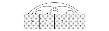
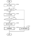
- FIGS. 1 and 2 are diagrams for explaining the prediction types of motion compensation prediction. It is a flowchart which shows the flow of operation
- FIGS. 8A and 8B are diagrams illustrating two prediction modes for encoding motion information used in motion compensated prediction according to the embodiment of the present invention. It is a figure which shows the detailed structure of the prediction mode determination part in the moving image encoder of embodiment. It is a figure which shows the structure of the joint motion information calculation part of FIG. 9 in embodiment. It is a flowchart explaining the detailed operation
- movement of the motion compensation prediction mode / predicted signal generation process of step S502 of FIG. 12 is a flowchart for explaining a detailed operation of the combined motion information candidate list generation of FIG. 11 in the embodiment. It is a figure which shows the space candidate block group used for a space joint motion information candidate list generation. It is a flowchart explaining the detailed operation
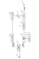
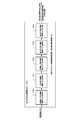
- FIG. 1 is a diagram showing a configuration of a moving picture coding apparatus according to an embodiment of the present invention. Hereinafter, the operation of each unit will be described.
- the moving image coding apparatus according to the embodiment includes an input terminal 100, a subtraction unit 101, an orthogonal transformation / quantization unit 102, a prediction error coding unit 103, an inverse quantization / inverse transformation unit 104, an addition unit 105, and a decoded image.
- a memory 106 a motion vector detection unit 107, a motion compensation prediction unit 108, a prediction mode determination unit 109, a motion information encoding unit 110, a motion information memory 111, a multiplexing unit 112, and an output terminal 113 are provided.
- the image signal of the prediction block to be encoded is extracted from the image signal input from the input terminal 100 based on the position information and the prediction block size of the prediction block, and the image signal of the prediction block is subtracted by the subtractor 101, the motion vector. This is supplied to the detection unit 107 and the prediction mode determination unit 109.
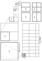
- FIG. 2 is a diagram illustrating an example of an encoding target image.
- the encoding target image is encoded in units of 64 ⁇ 64 pixel encoding blocks (CU), and the prediction block is further divided into encoding blocks. It is composed of units.
- the maximum prediction block size is 64 ⁇ 64 pixels, which is the same as the encoded block, and the minimum prediction block size is 4 ⁇ 4 pixels.
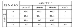
- the coding block is divided into prediction blocks: non-division (2N ⁇ 2N), horizontal / vertical division (N ⁇ N), horizontal only division (2N ⁇ N), and vertical division only (N ⁇ 2N) is possible. Only in the case of horizontal and vertical division, the further divided prediction block can be divided into prediction blocks hierarchically as encoded blocks, and the hierarchy is expressed by the number of CU divisions.
- FIG. 3 is a diagram showing a detailed definition of the predicted block size. There are 13 predicted block sizes from 64 pixels ⁇ 64 pixels, which is the maximum predicted block size with 0 CU divisions, to 4 pixels ⁇ 4 pixels, which is the minimum predicted block size with 3 CU partitions. Will exist.
- the prediction block division configuration according to the embodiment of the present invention is not limited to this combination.
- the selection of the prediction block size in the video encoding apparatus can adaptively select a structure with better encoding efficiency in units of encoding blocks, but the embodiment is a screen in units of prediction blocks. Since the focus is on inter-prediction and inter-frame motion information encoding, the components and description relating to the selection of the optimal prediction block size are omitted. Regarding the subsequent operation of the video encoding apparatus, the operation performed in units of the selected prediction block size will be described.
- the subtraction unit 101 subtracts the image signal supplied from the input terminal 100 and the prediction signal supplied from the prediction mode determination unit 109 to calculate a prediction error signal, and orthogonally transforms / quantizes the prediction error signal. To the conversion unit 102.
- the orthogonal transform / quantization unit 102 performs orthogonal transform and quantization on the prediction error signal supplied from the subtraction unit 101, and the quantized prediction error signal is subjected to a prediction error encoding unit 103 and an inverse quantization / inverse conversion unit. 104 is supplied.
- the prediction error encoding unit 103 entropy-encodes the quantized prediction error signal supplied from the orthogonal transform / quantization unit 102, generates a code string for the prediction error signal, and supplies the code sequence to the multiplexing unit 112 .
- the inverse quantization / inverse transform unit 104 performs processing such as inverse quantization and inverse orthogonal transform on the quantized prediction error signal supplied from the orthogonal transform / quantization unit 102, and outputs the decoded prediction error signal. Generated and supplied to the adding unit 105.
- the addition unit 105 adds the decoded prediction error signal supplied from the inverse quantization / inverse conversion unit 104 and the prediction signal supplied from the prediction mode determination unit 109, generates a decoded image signal, and outputs the decoded image signal.
- the decoded image memory 116 is supplied.
- the decoded image memory 106 stores the decoded image signal supplied from the adding unit 105.
- a decoded image for which decoding of the entire image has been completed is stored as a reference image by a predetermined number of images, and the reference image signal is supplied to the motion vector detection unit 107 and the motion compensation prediction unit 108.
- the motion vector detection unit 107 receives the prediction block image signal supplied from the input terminal 100 and the reference image signal stored in the decoded image memory 106, detects the motion vector for each reference image, and detects the motion vector. The value is supplied to the prediction mode determination unit 109.
- a general motion vector detection method calculates an error evaluation value for an image signal corresponding to a reference image moved by a predetermined movement amount from the same position as the image signal, and moves the movement amount that minimizes the error evaluation value. Let it be a vector.
- the error evaluation value a sum of absolute differences SAD (Sum of Absolute Difference) for each pixel, a sum of squared error values SSE (Sum of Square Error) for each pixel, or the like is used.
- the code amount related to the coding of the motion vector can also be included in the error evaluation value.
- the motion compensated prediction unit 108 refers to the reference image indicated by the reference image designation information in the decoded image memory 106 according to the prediction type, the reference image designation information designated by the prediction mode determination unit 109, the motion vector value, and the bi-prediction restriction information. Is acquired from the same position as the image signal of the prediction block by the motion vector value, and a prediction signal is generated.
- the prediction mode specified by the prediction mode determination unit 109 is uni-prediction, a prediction signal acquired from one reference image is used as a motion-compensated prediction signal.
- the prediction mode is bi-prediction, two reference images are used. A weighted average of the obtained prediction signals is used as a motion compensation prediction signal, and the motion compensation prediction signal is supplied to the prediction mode determination unit 109.
- the ratio of the weighted average of bi-prediction is set to 1: 1.
- motion compensated prediction may be performed with a prediction type different from the prediction type specified by the prediction mode determination unit 109.
- the motion compensation prediction unit 108 corrects the prediction type based on the bi-prediction restriction information and performs motion compensation prediction. Details of motion compensation prediction with a prediction type different from the designated prediction type will be described later.
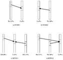
- 4 (a) to 4 (d) are diagrams for explaining the prediction type of motion compensation prediction.
- the process of performing prediction from a single reference image is defined as single prediction.
- single prediction one of reference images registered in two reference image management lists, L0 prediction and L1 prediction, is used.
- FIG. 4A shows a case in which the prediction image is uni-prediction and the reference image (RefL0Pic) for L0 prediction is at a time before the encoding target image (CurPic).
- FIG. 4B shows a case in which the prediction image is a single prediction and the reference image of the L0 prediction is at a time after the encoding target image.
- the L0 prediction reference image shown in FIGS. 4A and 4B can be replaced with the L1 prediction reference image (RefL1Pic) to perform single prediction.
- FIG. 4C illustrates a case where bi-prediction is performed, and the reference image for L0 prediction is at a time before the encoding target image and the reference image for L1 prediction is at a time after the encoding target image.
- FIG. 4D shows a case of bi-prediction, where the reference image for L0 prediction and the reference image for L1 prediction are at a time before the encoding target image.
- the relationship between the prediction type of L0 / L1 and time can be used without being limited to L0 being the past direction and L1 being the future direction.
- Bi-prediction requires image information access to two reference image memories, and therefore may require twice or more memory bandwidth compared to single prediction.
- bi-prediction when the prediction block size of motion compensation prediction is small becomes a bottleneck of the memory band, and in this embodiment, the bottleneck of the memory band is suppressed.
- the prediction mode determination unit 109 detects the motion vector value detected for each reference image input from the motion vector detection unit 107 and the motion information stored in the motion information memory 111 (prediction type, motion Based on the vector value and the reference image designation information), the prediction type, the reference image designation information, the motion vector value, and the bi-prediction restriction information used for each of the motion compensation prediction modes defined in the embodiment are moved.
- the compensation prediction unit 108 Based on the set value, an optimal motion compensation prediction mode is determined using the motion compensation prediction signal supplied from the motion compensation prediction unit 108 and the image signal of the prediction block supplied from the input terminal 100.
- the prediction mode determination unit 109 supplies information that identifies the determined prediction mode and the prediction type, motion vector, and reference image designation information corresponding to the prediction mode to the motion information encoding unit 110, and determines the determined prediction mode and A prediction type, a motion vector value, and reference image designation information for the prediction mode are supplied to the motion information memory 111, and a prediction signal corresponding to the determined prediction mode is supplied to the subtraction unit 101 and the addition unit 105.
- intra prediction is performed using an encoded image in the same screen, but the embodiment focuses on inter prediction. Therefore, the components related to the intra prediction are omitted.
- a detailed configuration of the prediction mode determination unit 109 will be described later.
- the motion information encoding unit 110 encodes the prediction mode supplied from the prediction mode determination unit 109 and information specifying the prediction type, the motion vector, and the reference image designation information according to the prediction mode according to a predetermined syntax structure. Thus, a code string of motion information is generated and supplied to the multiplexing unit 112.
- the motion information memory 111 stores motion information (prediction type, motion vector, and reference image index) supplied from the prediction mode determination unit 109 for a predetermined image on the basis of the minimum prediction block size unit.
- the motion information of the adjacent block of the prediction block to be processed is set as a spatial candidate block group, and the motion information of the block on the ColPic at the same position as the prediction block to be processed and its neighboring blocks is set as the time candidate block group.
- ColPic is a decoded image different from the prediction block to be processed, and is stored in the decoded image memory 106 as a reference image.
- ColPic is a reference image decoded immediately before.
- ColPic is the reference image decoded immediately before.
- the reference image immediately before in display order or the reference image immediately after in display order may be used, and the reference image used for ColPic is directly included in the encoded stream. It is also possible to specify.
- the motion information memory 111 supplies the motion information of the space candidate block group and the time candidate block group to the prediction mode determination unit 109 as motion information of the candidate block group.
- the multiplexing unit 112 multiplexes the prediction error encoded sequence supplied from the prediction error encoding unit 103 and the motion information encoded sequence supplied from the motion information encoding unit 110 to encode the encoded bit stream. And the encoded bit stream is output to the recording medium / transmission path via the output terminal 113.
- the configuration of the moving picture encoding apparatus shown in FIG. 1 can also be realized by hardware such as an information processing apparatus including a CPU (Central Processing Unit), a frame memory, and a hard disk.
- an information processing apparatus including a CPU (Central Processing Unit), a frame memory, and a hard disk.
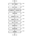
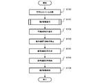
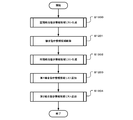
- FIG. 5 is a flowchart showing a flow of an encoding process in the moving image encoding apparatus according to the embodiment of the present invention.
- a prediction block image to be processed is acquired from the input terminal 100 for each prediction block unit (S500).
- the motion vector detection unit 107 calculates a motion vector value for each reference image from the prediction block image to be processed and a plurality of reference images stored in the decoded image memory 106 (S501).
- the prediction mode determination unit 109 uses the motion vector supplied from the motion vector detection unit 107 and the motion information stored in the motion information memory 111 for each of the motion compensation prediction modes defined in the embodiment.
- a prediction signal is acquired using the motion compensation prediction unit 108, an optimal prediction mode is selected, and a prediction signal is generated (S502). Details of the processing in step S502 will be described later.
- the subtraction unit 101 calculates a difference between the prediction block image to be processed and the prediction signal supplied from the prediction mode determination unit 109 as a prediction error signal (S503).
- the motion information encoding unit 110 encodes the prediction mode supplied from the prediction mode determination unit 109 and information specifying the prediction type, the motion vector, and the reference image designation information according to the prediction mode according to a predetermined syntax structure. Then, encoded data of motion information is generated (S504).
- the prediction error encoding unit 103 entropy encodes the quantized prediction error signal generated by the orthogonal transform / quantization unit 102 to generate encoded data of the prediction error (S505).
- the multiplexing unit 112 multiplexes the motion information encoded data supplied from the motion information encoding unit 110 and the prediction error encoded data supplied from the prediction error encoding unit 103 to generate an encoded bitstream. (S506).
- the addition unit 105 adds the decoded prediction error signal supplied from the inverse quantization / inverse conversion unit 104 and the prediction signal supplied from the prediction mode determination unit 109 to generate a decoded image signal (S507).
- the generated decoded image signal is supplied to and stored in the decoded image memory 106 by the adding unit 105, and is used for motion compensation prediction processing of an encoded image to be encoded later (S508).
- the motion information memory 111 stores the motion information (prediction type, motion vector, and reference image designation information) supplied from the motion vector detection unit 107 in units of the minimum predicted block size (S509).
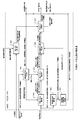
- FIG. 6 is a diagram showing a configuration of the video decoding apparatus according to the embodiment of the present invention.
- the video decoding apparatus includes an input terminal 600, a demultiplexing unit 601, a prediction difference information decoding unit 602, an inverse quantization / inverse transformation unit 603, an addition unit 604, a decoded image memory 605, and a motion information decoding unit 606. , A motion information memory 607, a motion compensation prediction unit 608, and an output terminal 609.
- the encoded bit stream is supplied from the input terminal 600 to the demultiplexing unit 601.
- the demultiplexing unit 601 includes motion information including a coded sequence of the supplied coded bitstream, a coded sequence of prediction error information, and information specifying a prediction mode, a prediction type, a motion vector, and reference image designation information. Are separated into encoded sequences.
- the encoded sequence of the prediction error information is supplied to the prediction difference information decoding unit 602, and the encoded sequence of the motion information is supplied to the motion information decoding unit 606.
- the prediction difference information decoding unit 602 decodes the encoded sequence of prediction error information supplied from the demultiplexing unit 601, and generates a quantized prediction error signal.
- the prediction difference information decoding unit 602 supplies the generated quantized prediction error signal to the inverse quantization / inverse transform unit 603.
- the inverse quantization / inverse transform unit 603 performs a process such as inverse quantization or inverse orthogonal transform on the quantized prediction error signal supplied from the prediction difference information decoding unit 602 to generate a prediction error signal, and performs decoding prediction.
- the error signal is supplied to the adding unit 604.
- the adder 604 adds the decoded prediction error signal supplied from the inverse quantization / inverse transform unit 603 and the prediction signal supplied from the motion compensation prediction unit 608 to generate a decoded image signal, and decodes the decoded image signal This is supplied to the image memory 605.
- the decoded image memory 605 has the same function as the decoded image memory 106 in the moving image encoding apparatus in FIG. 1, stores the decoded image signal supplied from the addition unit 604, and stores the reference image signal in the motion compensation prediction unit 608. Supply. Also, the decoded image memory 605 supplies the stored decoded image signal to the output terminal 609 in accordance with the image display order in accordance with the reproduction time.
- the motion information decoding unit 606 decodes, as motion information, information specifying the prediction mode, the prediction type, the motion vector, and the reference image designation information from the encoded sequence of motion information supplied from the demultiplexing unit 601. Based on the decoded motion information and the motion information of the candidate block group supplied from the motion information memory 607, the prediction type, motion vector, and reference image designation information used for motion compensation prediction are reproduced and supplied to the motion compensation prediction unit 608. In addition, the motion information decoding unit 606 supplies the reproduced motion information to the motion information memory 607. A detailed configuration of the motion information decoding unit 606 will be described later.
- the motion information memory 607 has the same function as that of the motion information memory 111 in the video encoding apparatus of FIG. 1, and reproduces the reproduced motion information supplied from the motion information decoding unit 606 for a predetermined image on the basis of the minimum prediction block size unit.
- the motion information memory 607 supplies the motion information of the space candidate block group and the time candidate block group to the motion information decoding unit 606 as motion information of the candidate block group.
- the motion compensation prediction unit 608 has the same function as that of the motion compensation prediction unit 108 in the video encoding apparatus in FIG. 1, and based on the motion information supplied from the motion information decoding unit 606, the reference image in the decoded image memory 605 A prediction signal is generated by acquiring an image signal at a position obtained by moving the reference image indicated by the designation information from the same position as the image signal of the prediction block by the motion vector value. If the prediction type of motion compensation prediction is bi-prediction, an average of the prediction signals of each prediction type is generated as a prediction signal, and the prediction signal is supplied to the adding unit 604. However, for a prediction block limited in bi-prediction, a prediction signal is generated as single prediction even if the prediction type is bi-prediction.
- motion compensated prediction may be performed using reference image designation information different from the reference image designation information designated by the motion information decoding unit 606. That is, the motion compensation prediction unit 608 corrects the prediction type based on the prediction type and the bi-prediction restriction information, and performs motion compensation prediction. Details of motion compensation prediction with a prediction type different from the designated prediction type will be described later.
- the output terminal 609 reproduces the decoded image signal by outputting the decoded image signal supplied from the decoded image memory 605 to a display medium such as a display.
- the configuration of the video decoding device shown in FIG. 6 can also be realized by hardware such as an information processing device including a CPU, a frame memory, a hard disk, etc., similarly to the configuration of the video encoding device shown in FIG. is there.
- FIG. 7 is a flowchart showing the flow of the decoding process in the moving picture decoding apparatus according to the embodiment of the present invention.
- the demultiplexing unit 601 separates the coded bit stream supplied from the input terminal 600 into a coded sequence of prediction error information and a coded sequence of motion information (S700).
- the separated coded sequence of motion information is supplied to the motion information decoding unit 606, and the motion information of the decoding target block is decoded using the motion information of the candidate block group supplied from the motion information memory 607 (S701). Details of the processing in step S701 will be described later.
- the separated coded sequence of prediction error information is supplied to the prediction difference information decoding unit 602, decoded as a quantized prediction error signal, and dequantized or inverse orthogonal transformed by an inverse quantization / inverse transformation unit 603.
- a decoded prediction error signal is generated (S702).
- the motion information decoding unit 606 supplies the motion information of the decoding target block to the motion compensation prediction unit 608, and the motion compensation prediction unit 608 performs motion compensation prediction according to the motion information to calculate a prediction signal (S703).
- the adding unit 604 adds the decoded prediction error signal supplied from the inverse quantization / inverse transform unit 603 and the prediction signal supplied from the motion compensation prediction unit 608 to generate a decoded image signal (S704).
- the decoded image signal supplied from the adding unit 604 is stored in the decoded image memory 605 (S705), and the motion information of the decoding target block supplied from the motion information decoding unit 606 is stored in the motion information memory 607 ( S706). This completes the decoding process in units of prediction blocks.
- FIGS. 8A and 8B are diagrams for explaining two prediction modes for encoding motion information used in motion compensated prediction according to the embodiment of the present invention.
- the prediction target block directly encodes its own motion information using the continuity of motion in the temporal direction and the spatial direction in the prediction target block and the encoded block adjacent to the prediction target block.
- the motion information of spatially and temporally adjacent blocks is used for encoding, which is called a joint prediction mode (merge mode).
- the prediction target block directly encodes its own motion information using the continuity of motion in the temporal direction and the spatial direction in the prediction target block and the encoded block adjacent to the prediction target block.
- the motion information of spatially and temporally adjacent blocks is used for encoding, which is called a joint prediction mode (merge mode).
- the spatially adjacent block refers to a block adjacent to the prediction target block among encoded blocks belonging to the same image as the prediction target block.
- the temporally adjacent blocks indicate blocks in the same spatial position as the prediction target block and in the vicinity thereof among blocks belonging to an encoded image different from the prediction target block.
- motion information that is selectively combined from a plurality of adjacent block candidates can be defined, and the motion information is encoded with information (index) that specifies the adjacent block to be used.
- the obtained motion information is used as it is for motion compensation prediction.
- a Skip mode is defined in which the prediction signal predicted in the joint prediction mode is a decoded picture without encoding prediction transmission of the prediction difference information, and a decoded image is obtained with information having only the combined motion information. Can be reproduced.
- the motion information transmitted in the Skip mode is designation information that defines adjacent blocks, as in the combined prediction mode.
- the second prediction mode is a technique for coding all the components of motion information individually and transmitting motion information with little prediction error to the prediction block, and is called a motion detection prediction mode.
- the motion detection prediction mode includes a prediction type indicating whether the prediction is bi-prediction or uni-prediction, information for identifying a reference image (reference image index), and encoding of motion information in the conventional motion compensation prediction.
- the information for specifying the motion vector is encoded separately.
- the prediction mode indicates whether to use single prediction or bi-prediction.
- single prediction single prediction information for specifying a reference image for one reference image, and a motion vector prediction vector
- the difference vector is encoded.
- bi-prediction information for specifying reference images for two reference images and a motion vector are individually encoded.
- the prediction vector for the motion vector is generated from the motion information of the adjacent block similarly to the AVC.
- the motion vector used for the prediction vector can be selected from a plurality of adjacent block candidates, and the motion vector is the prediction vector.
- the information is transmitted by encoding two pieces of information (index) for designating adjacent blocks to be used for and a difference vector.
- FIG. 9 is a diagram illustrating a detailed configuration of the prediction mode determination unit 109 in the video encoding device according to the embodiment.
- the prediction mode determination unit 109 has a function of determining an optimal motion compensation prediction mode.
- the prediction mode determination unit 109 includes a motion compensation prediction generation unit 900, a prediction error calculation unit 901, a prediction vector calculation unit 902, a difference vector calculation unit 903, a motion information code amount calculation unit 904, a prediction mode evaluation unit 905, and a combined motion information calculation.
- the motion vector value input from the motion vector detection unit 107 is supplied to the motion compensation prediction generation unit 900, and the motion information input from the motion information memory 111 is the prediction vector.
- the calculation unit 902 and the combined motion information calculation unit 906 are supplied.
- the motion compensation prediction generation unit 900 and the combined motion compensation prediction generation unit 907 output the prediction type, reference image designation information, and motion vector used for motion compensation prediction to the motion compensation prediction unit 108, and motion compensation
- the generated motion compensated prediction image is supplied from the prediction unit 108 to the prediction error calculation unit 901.
- the prediction error calculation unit 901 is further supplied with an image signal of a prediction block to be encoded from the input terminal 100.
- the motion information encoding unit 110 is supplied with motion information to be encoded and the determined prediction mode information from the prediction mode evaluation unit 905, the motion information is supplied to the motion information memory 111, and the motion compensated prediction signal is subtracted. To the unit 101 and the addition unit 105.
- the motion compensation prediction generation unit 900 receives a motion vector value calculated for each reference image that can be used for prediction, performs motion compensation prediction according to bi-prediction restriction information, and generates reference image designation information as a prediction vector calculation unit 902. To output reference image designation information and motion vectors.
- the prediction error calculation unit 901 calculates a prediction error evaluation value from the input motion compensated prediction image and the prediction block image to be processed.
- the sum SAD of the absolute difference value for each pixel, the sum SSE of the square error value for each pixel, and the like can be used as in the error evaluation value in motion vector detection.
- a more accurate error evaluation value can be calculated by taking into account the amount of distortion components generated in the decoded image by performing orthogonal transform / quantization performed when encoding the prediction residual.
- the prediction error calculation unit 901 can be realized by having the functions of the subtraction unit 101, the orthogonal transformation / quantization unit 102, the inverse quantization / inverse transformation unit 104, and the addition unit 105 in FIG.
- the prediction error calculation unit 901 supplies the prediction error evaluation value calculated in each prediction mode and the motion compensation prediction signal to the prediction mode evaluation unit 905.
- the prediction vector calculation unit 902 is supplied with the reference image designation information from the motion compensation prediction generation unit 900, and the motion vector value for the designated reference image from the candidate block group in the motion information of the adjacent block supplied from the motion information memory 111. Are generated together with the prediction vector candidate list, and supplied to the difference vector calculation unit 903 together with the reference image designation information.
- the prediction vector calculation unit 902 creates prediction vector candidates and registers them as prediction vector candidates.
- the difference vector calculation unit 903 calculates the difference between each of the prediction vector candidates supplied from the prediction vector calculation unit 902 and the motion vector value supplied from the motion compensated prediction generation unit 900, and calculates the difference vector value. calculate.
- the prediction vector index which is the designation information for the calculated difference vector value and the prediction vector candidate is encoded
- the code amount is the smallest.
- the difference vector calculation unit 903 supplies the prediction vector index and the difference vector value for the prediction vector having the smallest information amount, together with the reference image designation information, to the motion information code amount calculation unit 904.
- the motion information code amount calculation unit 904 calculates the code amount required for motion information in each prediction mode from the difference vector value, reference image designation information, prediction vector index, and prediction mode supplied from the difference vector calculation unit 903. . Also, the motion information code amount calculation unit 904 receives information indicating the combined motion information index and the prediction mode that need to be transmitted in the combined prediction mode from the combined motion compensation prediction generation unit 907, and performs motion in the combined prediction mode. The amount of code required for information is calculated.
- the motion information code amount calculation unit 904 supplies the motion information calculated in each prediction mode and the code amount required for the motion information to the prediction mode evaluation unit 905.
- the prediction mode evaluation unit 905 uses the prediction error evaluation value of each prediction mode supplied from the prediction error calculation unit 901 and the motion information code amount of each prediction mode supplied from the motion information code amount calculation unit 904. An overall motion compensation prediction error evaluation value for the prediction mode is calculated, a prediction mode having the smallest evaluation value is selected, motion information for the selected prediction mode and the selected prediction mode, a motion information encoding unit 110, a motion information memory To 111. Similarly, the prediction mode evaluation unit 905 selects a prediction signal in the selected prediction mode for the motion compensated prediction signal supplied from the prediction error calculation unit 901 and outputs it to the subtraction unit 101 and the addition unit 105.
- the combined motion information calculation unit 906 uses a candidate block group in the motion information of the adjacent blocks supplied from the motion information memory 111, a prediction type indicating whether it is uni-prediction or bi-prediction, reference image designation information, motion A plurality of pieces of motion information are generated together with the combined motion information candidate list as motion information composed of vector values, and supplied to the combined motion compensation prediction generation unit 907.
- FIG. 10 is a diagram illustrating a configuration of the combined motion information calculation unit 906.
- the combined motion information calculation unit 906 includes a spatial combined motion information candidate list generation unit 1000, a combined motion information candidate list deletion unit 1001, a temporal combined motion information candidate list generation unit 1002, a first combined motion information candidate list addition unit 1003, and a second.
- a combined motion information candidate list adding unit 1004 is included.
- the combined motion information calculation unit 906 creates motion information candidates in a predetermined order from spatially adjacent candidate block groups, deletes candidates having the same motion information from the candidates, and then temporally adjacent. By adding motion information candidates created from the candidate block group, only valid motion information is registered as combined motion information candidates.
- this temporally combined motion information candidate list generation unit is arranged after the combined motion information candidate list deletion unit is a characteristic configuration of the present embodiment, and deletes the same motion information from temporally combined motion information candidates. By eliminating the processing target, it is possible to reduce the amount of calculation without reducing the encoding efficiency.
- the detailed operation of the combined motion information calculation unit 906 will be described later.
- the combined motion compensation prediction generation unit 907 determines, based on the motion information, the prediction type for each registered combined motion information candidate from the combined motion information candidate list supplied from the combined motion information calculation unit 906. In accordance with the reference image designation information and motion vector value of one reference image (uni-prediction) or two reference images (bi-prediction), the motion compensated prediction unit 108 is designated to generate a motion compensated prediction image, The combined motion information index is supplied to the motion information code amount calculation unit 904.
- the motion compensation prediction unit 108 corrects the prediction type based on the prediction type, reference image designation information, motion vector value, and bi-prediction restriction information, and performs motion compensation prediction. Details of motion compensation prediction with a prediction type different from the supplied prediction type will be described later.
- the prediction mode evaluation for each combined motion information index is performed by the prediction mode evaluation unit 905.
- the prediction error evaluation value and the motion information code amount are calculated by the prediction error calculation unit 901 and the motion information code amount calculation.
- the combined motion compensated prediction generation unit 907 the optimal combined motion index of the optimal combined motion compensated prediction is determined and then the optimal prediction mode including other prediction modes is evaluated. Is possible.
- FIG. 11 is a flowchart for explaining the detailed operation of the motion compensation prediction mode / prediction signal generation process in step S502 of FIG. This operation shows the detailed operation in the prediction mode determination unit 109 of FIG.
- a combined motion information candidate list is generated (S1100), and a combined prediction mode evaluation value is generated (S1101). Subsequently, a prediction mode evaluation value is generated (S1102), and the optimal evaluation mode is selected by comparing the generated evaluation values (S1103).
- the order of evaluation value generation in steps S1101 and S1102 is not limited to this.
- the prediction signal is output according to the selected prediction mode (S1104), and the motion information is output according to the selected prediction mode (S1105), thereby completing the motion compensation prediction mode / prediction signal generation process for each prediction block.
- steps S1100, S1101, and S1102 will be described later.
- FIG. 12 is a flowchart for explaining the detailed operation of generating the combined motion information candidate list in step S1100 of FIG. This operation shows the detailed operation of the configuration in the combined motion information calculation unit 906 in FIG.
- the spatially coupled motion information candidate list generation unit 1000 in FIG. 10 performs spatially coupled motion from candidate blocks excluding candidate blocks outside the region or candidate blocks in the intra mode from the spatial candidate block group supplied from the motion information memory 111.
- An information candidate list is generated (S1200). Detailed operations for generating the spatially coupled motion information candidate list will be described later.
- the combined motion information candidate list deletion unit 1001 deletes the combined motion information candidates having the same motion information from the generated spatial combined motion information candidate list and updates the motion information candidate list (S1201). Detailed operation of the combined motion information candidate deletion will be described later.
- the temporally combined motion information candidate list generation unit 1002 subsequently extracts temporally combined motion information from candidate blocks excluding candidate blocks outside the region from the temporal candidate block group supplied from the motion information memory 111 and candidate blocks that are in the intra mode.
- a candidate list is generated (S1202) and combined with the temporally combined motion information candidate list to form a combined motion information candidate list. Detailed operation of the time combination motion information candidate list generation will be described later.
- the first combined motion information candidate list adding unit 1003 outputs 0 to 2 first combined motion information candidates from the combined motion information candidates registered in the combined motion information candidate list generated by the temporal combined motion information candidate list generating unit 1002.
- a combined motion information candidate is generated and added to the combined motion information candidate list (S1203), and the combined motion information candidate list is supplied to the second combined motion information candidate list adding unit 1004. The detailed operation of adding the first combined motion information candidate list will be described later.
- the second combined motion information candidate list adding unit 1004 selects 0 to 4 second combined motion information candidates that do not depend on the combined motion information candidate list supplied from the first combined motion information candidate list adding unit 1003.
- the generated combined motion information candidate list is added to the combined motion information candidate list supplied from the first combined motion information candidate list adding unit 1003 (S1204), and the process ends. Detailed operations for adding the second combined motion information candidate list will be described later.
- the candidate block group of motion information supplied from the motion information memory 111 to the combined motion information calculation unit 906 includes a spatial candidate block group and a temporal candidate block group. First, generation of a spatially coupled motion information candidate list will be described.
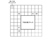
- FIG. 13 is a diagram showing a spatial candidate block group used for generating a spatially coupled motion information candidate list.
- the spatial candidate block group indicates a block of the same image adjacent to the prediction target block of the encoding target image.
- the block group is managed in units of the minimum prediction block size, and the position of the candidate block is managed in units of the minimum prediction block size, but when the prediction block size of the adjacent block is larger than the minimum prediction block size
- the same motion information is stored in all candidate blocks within the predicted block size.
- five blocks of block A0, block A1, block B0, block B1, and block B2 as shown in FIG. 13 are set as space candidate block groups.
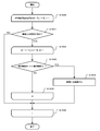
- FIG. 14 is a flowchart for explaining the detailed operation of generating the spatially coupled motion information candidate list.
- the following processing is repeated for block A0, block A1, block B0, block B1, and block B2 in the order of block A1, block B1, block B0, and block A0. (S1400 to S1403).
- the validity of the candidate block is checked (S1401). If the candidate block is not out of the region and not in the intra mode, the candidate block is valid. If the candidate block is valid (S1401: YES), the motion information of the candidate block is added to the spatially combined motion information candidate list (S1402).
- step S1400 If the number of candidates added to the spatially coupled motion information candidate list is less than 4 following the iterative processing from step S1400 to S1403 (S1404: YES), the validity of candidate block B2 is checked (S1405). When the block B2 is not out of the region and is not in the intra mode (S1405: YES), the motion information of the block B2 is added to the spatially coupled motion information candidate list (S1406).
- the spatial combination motion information candidate list includes motion information of four or less candidate blocks, but the spatial candidate block group is at least one or more processed blocks adjacent to the prediction block to be processed.
- the number of spatially coupled motion information candidate lists may be changed depending on the effectiveness of the candidate block, and the present invention is not limited to this.
- FIG. 16 shows a comparison relationship of candidates in the list when there are four combined motion information candidates. That is, four spatially combined motion information candidates that do not include temporally combined motion information candidates are compared by brute force to determine identity, and duplicate candidates are deleted.
- the joint prediction mode uses temporal and spatial continuity of motion
- the prediction target block encodes motion information of spatially and temporally adjacent blocks without directly encoding its own motion information.
- the spatially coupled motion information candidate is based on continuity in the spatial direction
- the temporally coupled motion information candidate is generated by the method described later based on the temporal direction continuity. These properties are different. Therefore, it is rare that the same motion information is included in the temporally combined motion information candidate and the spatially combined motion information candidate, and the temporally combined motion information candidate is removed from the target of the combined motion information candidate deletion process for deleting the same motion information. Even if they are excluded, it is rare that the same motion information is included in the finally obtained combined motion information candidate list.
- temporally combined motion information candidate blocks are managed in units of minimum time prediction blocks that are larger in size than the minimum prediction block, so that the size of prediction blocks that are temporally adjacent are larger than the minimum time prediction block If it is small, motion information at a position deviating from the original position is used, and as a result, the motion information often includes an error. Therefore, the motion information is often different from the motion information of the spatially coupled motion information candidate, and there is little influence even if the motion information is excluded from the target of the combined motion information candidate deletion process for deleting the same motion information.
- FIG. 17 is an example of comparison contents of candidates in the combined motion information candidate deletion when the maximum number of spatially combined motion information candidates is 4.
- FIG. 17A shows the comparison contents when only the spatially coupled motion information candidate is the target of the coupled motion information candidate deletion process
- FIG. 17B is the target of processing the spatially coupled motion information candidate and the temporally coupled motion information. It is a comparison content in the case of.
- the number of motion information comparisons is reduced from 10 to 6 while appropriately deleting the same motion information. Is possible.
- the combined motion information calculated from the B1 position in FIG. 13 is compared with the combined motion information at the A1 position, and the combined motion information calculated from the B0 position is compared with only the combined motion information at the B1 position.
- the number of motion information comparisons can be limited to a maximum of five.
- FIG. 18 is a diagram illustrating the definition of the temporal direction peripheral prediction block used for generating the temporally combined motion information candidate list.
- the temporal candidate block group indicates blocks in the same position as and around the prediction target block among the blocks belonging to the decoded image ColPic different from the image to which the prediction target block belongs.
- the block group is managed in units of minimum time prediction block size, and the positions of candidate blocks are managed in units of minimum time prediction block size.
- the minimum temporal prediction block size is twice the minimum prediction block size in the vertical and horizontal directions.
- FIG. 18B shows motion information of the temporal direction neighboring prediction block when the prediction block size is smaller than the minimum temporal prediction block size.
- blocks at positions A1 to A4, B1 to B4, C, D, E, F1 to F4, G1 to G4, H, and I1 to I16 are temporally adjacent block groups.
- the temporal candidate block group is assumed to be two blocks, block H and block I6.
- FIG. 19 is a flowchart for explaining the detailed operation of generating the time combination motion information candidate list.
- the validity of the candidate block is checked in the order of the block H and the block I11 (S1801). If the candidate block is valid (S1801: YES), the processing of step S1802 to step S1804 is performed, the generated motion information is registered in the temporally combined motion information candidate list, and the processing ends.
- the candidate block indicates a position outside the screen area, or when the candidate block is an intra prediction block (S1801: NO)
- the candidate block is not valid, and valid / invalid determination of the next candidate block is performed.
- the reference image selection candidate to be registered in the combined motion information candidate is determined based on the motion information of the candidate block (S1802).
- the L0 prediction reference image is the reference image closest to the processing target image among the L0 prediction reference images
- the L1 prediction reference image is the most processing target image among the L1 prediction reference images. A reference image at a close distance is used.
- the method for determining the reference image selection candidate here is not limited to this as long as the reference image for L0 prediction and the reference image for L1 prediction can be determined.
- the reference image intended at the time of encoding can be determined by determining the reference image by the same method in the encoding process and the decoding process.
- a method of selecting a reference image having a reference image index of 0 for a reference image for L0 prediction and a reference image for L1 prediction, or a L0 reference image and a L1 reference image used by spatially neighboring blocks. can be used, and a method of specifying a reference image of each prediction type in the encoded stream can be used.
- the motion vector value to be registered in the combined motion information candidate is determined based on the motion information of the candidate block (S1803).
- the temporally coupled motion information calculates bi-prediction motion information based on a motion vector value that is an effective prediction type in motion information of candidate blocks.
- the prediction type of the candidate block is L0 prediction or L1 prediction single prediction
- motion information of the prediction type (L0 prediction or L1 prediction) used for prediction is selected, and its reference image designation information and motion vector value are selected. Is a reference value for generating bi-predictive motion information.
- L0 prediction or L1 prediction motion information is selected as a reference value.
- the reference value selection method selects, for example, motion information existing in the same prediction type as ColPic, and selects a reference image having a shorter inter-image distance from ColPic in each of L0 prediction and L1 prediction of a candidate block. For example, it is possible to select the transmission side and explicitly transmit the syntax.
- the motion vector value used as the reference for bi-predictive motion information generation is determined, the motion vector value to be registered in the combined motion information candidate is calculated.
- FIG. 20 is a diagram for explaining a calculation method of motion vector values mvL0t and mvL1t registered for L0 prediction and L1 prediction with respect to the reference motion vector value ColMv for temporally coupled motion information.
- the distance between images between ColPic for the reference motion vector value ColMv and the reference image that is the target of the motion vector used as a reference for the candidate block is referred to as ColDist.
- the inter-image distance between each reference image of L0 prediction and L1 prediction and the processing target image is set to CurrL0Dist and CurrL1Dist.
- a motion vector obtained by scaling ColMv with a distance ratio of ColDist to CurrL0Dist and CurrL1Dist is set as a motion vector to be registered.
- the motion vector values mvL0t and mvL1t to be registered are calculated by the following formulas 1 and 2.
- mvL0t mvCol ⁇ CurrL0Dist / ColDist (Formula 1)
- mvL1t mvCol ⁇ CurrL1Dist / ColDist (Formula 2) It becomes.
- the bi-predicted reference image selection information (index) and the motion vector value generated in this way are added to the combined motion information candidates (S1804), and the temporal combined motion information candidate list creation process ends. To do.
- FIG. 21 is a flowchart for explaining the operation of the first combined motion information candidate list adding unit 1003.
- NumCandList the number of combined motion information candidates
- MaxNumMergeCand the maximum number of combined motion information candidates registered in the combined motion information candidate list supplied from the temporally combined motion information candidate list generation unit 1002
- MaxNumGenCand which is the maximum number for generating motion information candidates, is calculated from Equation 3 (S2000).
- MaxNumGenCand MaxNumMergeCand-NumCandList; (NumCandList> 1)
- MaxNumGenCand is larger than 0 (S2001). If MaxNumGenCand is not greater than 0 (NO in S2001), the process ends. If MaxNumGenCand is greater than 0 (YES in S2001), the following processing is performed. First, loopTimes that is the number of combination inspections is determined. loopTimes is set to NumCandList ⁇ NumCandList. However, if loopTimes exceeds 8, loopTimes is limited to 8 (S2002). Here, loopTimes is an integer from 0 to 7. The following processing is repeated for loopTimes (S2002 to S2008).
- the combination of combined motion information candidate M and combined motion information candidate N is determined (S2003).
- the relationship between the number of combination inspections, the combined motion information candidate M, and the combined motion information candidate N will be described.
- FIG. 22 is a diagram for explaining the relationship between the number of combination inspections, the combined motion information candidate M, and the combined motion information candidate N.
- M and N are different values. First, M is fixed to 0, the value of N is changed to 1 to 4 (the maximum value is NumCandList), and then the value of N is fixed to 0. The value of M is changed to 1 to 4 (the maximum value is NumCandList).
- Such a combination definition makes effective use of the first motion information in the combined motion information candidate list, which is the motion information with the highest probability of being selected, and actually calculates the combination pattern without having a combination table. There is an effect that can be calculated.
- the combined motion information candidate M uses the motion vector of the L0 prediction of the combined motion information candidate M and the reference image.
- a combined motion information candidate is generated by combining the motion vector of N L1 predictions with the reference image (S2005). If the L0 prediction of the combined motion information candidate M is not valid and the L1 prediction of the combined motion information candidate N is not valid (NO in S2004), the next combination is processed.
- the motion information of the L0 prediction and the L1 prediction may be the same, and even if motion compensation is performed by bi-prediction, the same result as the single prediction of the L0 prediction or the L1 prediction is obtained. Therefore, the additional combined motion information candidate generation in which the motion information of the L0 prediction and the motion information of the L1 prediction are the same is a factor that increases the calculation amount of the motion compensation prediction. Therefore, normally, whether the motion information of the L0 prediction and the motion information of the L1 prediction are the same is compared, and only when the motion information is not the same, the motion information is determined as the first additional combined motion information candidate.
- the motion compensation prediction unit which will be described later, performs a process of collectively converting bi-prediction into single prediction, so the motion information and L1 prediction of the L0 prediction in the first additional combined motion information candidate list adding unit Therefore, it is not necessary to determine the identity of the motion information, and the amount of calculation can be reduced.
- the bi-join motion information candidate is added to the combined motion information candidate list (S2006).
- step S2006 it is checked whether the number of generated double coupled motion information is MaxNumGenCand (S2007). If the number of generated double coupled motion information is MaxNumGenCand (YES in S2007), the process ends. If the number of generated double coupled motion information is not MaxNumGenCand (NO in S2007), the next combination is processed.
- the first additional combined motion information candidate is a combined motion information candidate when there is a slight difference between the motion information of the combined motion information candidate registered in the combined motion information candidate list and the motion information candidate motion to be processed. Coding efficiency can be improved by correcting the motion information of the combined motion information candidates registered in the list to generate effective combined motion information candidates.
- FIG. 23 is a flowchart for explaining the operation of the second combined motion information candidate list adding unit 1004.
- NumCandList the number of combined motion information candidates
- MaxNumMergeCand the maximum number of combined motion information candidates registered in the combined motion information candidate list supplied from the first combined motion information candidate list adding unit 1003.
- MaxNumGenCand which is the maximum number for generating combined motion information candidates, is calculated from Equation 4 (S2200).
- MaxNumGenCand MaxNumMergeCand-NumCandList; (Formula 4)
- i is an integer from 0 to MaxNumGenCand-1.
- the second additional combined motion in which the motion vector for L0 prediction is (0,0), the reference index is i, the motion vector for L1 prediction is (0,0), and the prediction type is i for the reference index is bi-prediction.
- Information candidates are generated (S2202).
- the second additional combined motion information candidate is added to the combined motion information candidate list (S2203).
- the next i is processed (S2204).
- the second additional combined motion information candidate has a motion vector for L0 prediction of (0, 0), a reference index of i, a motion vector of L1 prediction of (0, 0), and a reference index of i.
- the combined motion information candidate whose prediction type is bi-prediction was used. This is because, in a general moving image, the frequency of occurrence of combined motion information candidates in which the motion vector for L0 prediction and the motion vector for L1 prediction are (0, 0) is statistically high.
- the present invention is not limited to this as long as it is a combined motion information candidate that is statistically frequently used without depending on the motion information of the combined motion information candidate registered in the combined motion information candidate list.
- the motion vectors of L0 prediction and L1 prediction may be vector values other than (0, 0), respectively, and may be set so that the reference indexes of L0 prediction and L1 prediction are different.
- the second additional combined motion information candidate can be set as an encoded image or motion information with a high occurrence frequency of a part of the encoded image, encoded in an encoded stream, and transmitted.
- the motion compensation is performed by bi-prediction as in the first additional combined motion information candidate list generation unit.
- the additional combined motion information candidate generation in which the reference image of the L0 prediction and the reference image of the L1 prediction are the same increases the calculation amount of the motion compensation prediction. It becomes a factor.
- the motion compensation prediction unit which will be described later, performs a process of collectively converting bi-prediction into single prediction, so that the motion information and L1 prediction of the L0 prediction in the second additional combined motion information candidate list addition unit Therefore, it is not necessary to determine the identity of the motion information, and the amount of calculation can be reduced.
- the combined motion information candidate registered in the combined motion information candidate list When the number is zero, it is possible to use the joint prediction mode and improve the encoding efficiency.
- the motion information of the combined motion information candidate registered in the combined motion information candidate list and the motion information candidate motion to be processed are different, by generating a new combined motion information candidate and expanding the range of options, Encoding efficiency can be improved.
- FIG. 24 is a flowchart for explaining the detailed operation of the combined prediction mode evaluation value generation process in step S1101 of FIG. This operation shows the detailed operation of the configuration using the combined motion compensation prediction generation unit 907 of FIG.
- the motion information stored in the index i is acquired from the combined motion information candidate list (S2302). Subsequently, a motion information code amount is calculated (S2303). In the joint prediction mode, since only the joint motion information index is encoded, only the joint motion information index becomes the motion information code amount.
- a Truncated Unary code string is used as the code string of the combined motion information index.
- FIG. 25 is a diagram illustrating a truncated unary code string when the number of combined motion information candidates is five.
- the value of the combined motion information index is encoded using the Truncated Unary code string, the smaller the combined motion information index, the smaller the code bits assigned to the combined motion information index.
- the number of combined motion information candidates is 5, if the combined motion information index is 1, it is represented by 2 bits of “10”, but if the combined motion information index is 3, 4 bits of “1110”. It is expressed by
- the Truncated Unary code string is used to encode the combined motion information index, but other code string generation methods can be used, and the present invention is not limited to this.
- the motion compensation prediction unit 108 when the prediction type of motion information is single prediction (S2304: YES), the motion compensation prediction unit 108 generates a motion compensation single prediction block using reference image designation information and a motion vector for one reference image. (S2307).
- the motion compensated prediction unit 108 includes the motion information for L0 prediction and the motion information (reference image information and motion vector) for L1 prediction. It is determined whether the motion information of the L0 prediction and the motion information of the L1 prediction are the same (S2305: YES), and the L0 single prediction motion compensation prediction is performed using only the motion information of the L0 prediction (S2308). . However, the motion information of bi-prediction is maintained and the motion information of L1 prediction is not changed.
- the prediction block size is equal to or smaller than the bi-prediction restriction size, and the prediction block size is equal to or smaller than the bi-prediction restriction block size.
- the L0 single prediction motion compensation prediction is performed using only the motion information of the L0 prediction ( S2308).
- the motion information of bi-prediction is maintained and the motion information of L1 prediction is not changed.
- the purpose of the bi-prediction restriction is to limit the memory band of motion compensation prediction by restricting the bi-prediction to the single prediction. Therefore, the prediction list (L0 / L1) restricted by the bi-prediction restriction is set to the L1 single prediction. Of course it is good.
- the bi-prediction restricted block size is a block less than 8x8.
- the threshold is not limited to 8 ⁇ 8
- the bi-prediction restricted block size may be set to other values as long as it is between the maximum prediction block size and the minimum prediction block size.
- the threshold is not limited to 8 ⁇ 8 blocks including 8 ⁇ 8 blocks. May be set. You may explicitly transmit in the bit stream from the encoding side to the decoding side in the syntax.
- it is transmitted from the encoding side as a flag indicating whether or not bi-prediction restriction is performed with a predetermined block size (for example, 8 ⁇ 8), and predetermined on the decoding side. It may be determined whether or not the bi-prediction restriction is performed based on the block size.
- the motion compensated prediction unit 108 When the prediction block size is not less than or equal to the bi-prediction restricted block size (S2306: NO), the motion compensated prediction unit 108 generates a motion compensated bi-prediction block using reference image designation information and motion vectors for two reference images (S2306). .
- a prediction error evaluation value is calculated from the prediction error and the motion information code amount of the motion compensated prediction block and the prediction target block (S2310). If the prediction error evaluation value is the minimum value, the evaluation value is updated. Then, the prediction error minimum index is updated (S2311).
- a predetermined prediction block size is collectively added at the time of motion compensation prediction after motion information determination, instead of adding a condition determination as to whether it is equal to or smaller than the predetermined prediction block size.
- the prediction type of the following prediction block is bi-prediction, by performing motion compensation prediction as single prediction in the L0 direction, it is possible to suppress the memory bandwidth of motion compensation prediction with the addition of a minimum conditional branch.
- the prediction signal is the same as the single prediction, the motion information can maintain a combined motion information candidate that is bi-predicted. As a result, as shown in FIG.
- bi-prediction information can be used as it is, and the prediction efficiency of the motion prediction processing of a prediction block to be encoded / decoded thereafter can be improved.
- bi-prediction motion information can also be used as motion information when predicting an enhancement layer from a base layer.
- bi-prediction restriction is defined as an encoding / decoding standard, only L0 prediction information is used for motion compensation prediction in decoding defined by the standard, but bi-prediction motion information is used outside the decoding standard. Therefore, image quality can be improved by performing motion compensation prediction.
- the selected prediction error minimum index is used as the combined motion information index used in the combined prediction mode. It outputs together with a motion compensation prediction block (S2312), and complete
- FIG. 26 is a flowchart for explaining the detailed operation of the prediction mode evaluation value generation process in step S1102 of FIG.
- the prediction mode is single prediction (S2500). However, if it is equal to or smaller than the bi-prediction restricted block size, since it is implicitly L0 single prediction, it is not necessary to determine whether or not it is single prediction (S2500).
- FIG. 32 shows a syntax regarding motion information of a prediction block.
- merge_flag indicates whether or not the mode is the joint prediction mode
- merge_flag 0 indicates the motion detection prediction mode.
- a flag inter_pred_flag indicating whether the prediction type is uni-prediction or bi-prediction is transmitted.
- bi_pred_flag is transmitted without prohibiting bi-prediction. That is, when motion information is transmitted with the prediction type as bi-prediction, motion information of L0 and L1 is transmitted, but motion compensation prediction is performed by L0 simple prediction.
- bi-prediction information can be used as it is, and it is possible to improve the prediction efficiency of motion prediction processing of a prediction block that is encoded and decoded thereafter.
- bi-prediction motion information can also be used as motion information when predicting an enhancement layer from a base layer.
- bi-prediction restriction is defined as an encoding / decoding standard
- only L0 prediction information is used for motion compensation prediction in decoding defined by the standard
- bi-prediction motion information is used outside the decoding standard. Therefore, image quality can be improved by performing motion compensation prediction.
- decoding a decoded image that does not become a reference image even if bi-prediction is performed on a prediction block that is limited to bi-prediction, it is normal without affecting the motion compensated prediction of the subsequent decoded picture. It is more effective because it can be decrypted.
- the reference image list (LX) to be processed is set as the reference image list used for prediction (S2501). If it is not uni-prediction, it is bi-prediction, so LX is set to L0 in this case (S2502).
- reference image designation information (index) and motion vector values for LX prediction are acquired (S2503).
- a prediction vector candidate list is generated (S2504), an optimal prediction vector is selected from the prediction vectors, and a difference vector is generated (S2505). It is desirable to select the optimal prediction vector with the least amount of code when the difference vector between the prediction vector and the motion vector to be transmitted is actually encoded. However, the horizontal and vertical components of the difference vector are simply selected. The calculation may be simplified by a method such as selecting one having a small absolute sum.
- step S2506 it is determined again whether or not the prediction mode is single prediction (S2506). If the prediction mode is single prediction, the process proceeds to step S2509. If it is not uni-prediction, that is, if it is bi-prediction, it is determined whether or not the reference list LX to be processed is L1 (S2507). If the reference list LX is L1, the process proceeds to step S2509. If it is not L1, that is, if it is L0, LX is set to L1 (S2508), and the same processing as the processing from step S2503 to step S2506 is performed.
- a motion information code amount is calculated (S2509).
- the motion information to be encoded includes the prediction type, four elements of reference image designation information, difference vector value, and prediction vector index for one reference image, and prediction in the case of the bi-prediction mode.
- a prediction vector index code string generation method a Truncated Unary code string is used in the same manner as the combined motion information index code string.
- the motion compensated prediction unit 108 in FIG. 1 generates a motion compensated prediction block using the reference image designation information and the motion vector for the reference image (S2510).
- the motion detection prediction mode as in the operation for the combined prediction mode, for a prediction block that is limited to bi-prediction of a predetermined block size or less, even if the prediction type of motion information is bi-prediction, the L0 single Motion compensation prediction is performed as prediction.
- a prediction error evaluation value is calculated from the prediction error and the motion information code amount of the motion compensated prediction block and the prediction target block (S2511), and the prediction error evaluation value, the prediction type, and the reference image that is the motion information for the reference image.
- the designation information, the difference vector value, and the prediction vector index are output together with the motion compensated prediction block (S2512), and the prediction mode evaluation value generation process ends.
- the above processing is the detailed operation of the prediction mode determination unit 109 in the video encoding device in the embodiment.
- FIG. 27 is a diagram showing a detailed configuration of the motion information decoding unit 606 in the moving picture decoding apparatus according to the embodiment shown in FIG.
- the motion information decoding unit 606 includes a motion information bitstream decoding unit 2600, a prediction vector calculation unit 2601, a vector addition unit 2602, a motion compensation prediction decoding unit 2603, a combined motion information calculation unit 2604, and a combined motion compensation prediction decoding unit 2605. .
- the motion information bitstream input from the demultiplexing unit 601 is supplied to the motion information bitstream decoding unit 2600, and the motion information input from the motion information memory 607 is predicted. This is supplied to the vector calculation unit 2601 and the combined motion information calculation unit 2604.
- the motion compensation prediction unit 608 outputs the prediction type, the reference image designation information, and the motion vector used for motion compensation prediction from the motion compensation prediction decoding unit 2603 and the combined motion compensation prediction decoding unit 2605 and decoded.
- the motion information is stored in the motion information memory 607.
- the motion information bitstream decoding unit 2600 generates the motion information corresponding to the transmitted prediction mode and the prediction mode by decoding the motion information bitstream input from the demultiplexing unit 601 according to the encoding syntax. To do. Among the generated motion information, the combined motion information index is supplied to the combined motion compensation prediction decoding unit 2605, the reference image designation information is supplied to the prediction vector calculation unit 2601, and the prediction vector index is supplied to the vector addition unit 2602. The difference vector value is supplied to the vector addition unit 2602.
- the prediction vector calculation unit 2601 predicts a reference image to be subjected to motion compensation prediction from the motion information of the adjacent block supplied from the motion information memory 607 and the reference image designation information supplied from the motion information bitstream decoding unit 2600.
- a vector candidate list is generated and supplied to the vector addition unit 2602 together with the reference image designation information.
- the same operation as that of the prediction vector calculation unit 902 of FIG. 9 in the moving image encoding apparatus is performed, and the same candidate list as the prediction vector candidate list at the time of encoding is generated.
- the vector addition unit 2602 indicates a prediction vector index from the prediction vector candidate list and reference image designation information supplied from the prediction vector calculation unit 2601 and the prediction vector index and difference vector supplied from the motion information bitstream decoding unit 2600. By adding the prediction vector value and the difference vector value registered at the set position, the motion vector value for the reference image to be motion compensated prediction is reproduced. The reproduced motion vector value is supplied to the motion compensated prediction decoding unit 2603 together with the reference image designation information and the prediction type.
- the motion compensated prediction decoding unit 2603 is supplied with the reconstructed motion vector value, reference image designation information, and prediction type for the reference image from the vector addition unit 2602, and motion compensated prediction is performed on the motion vector value, the reference image designation information, and the prediction type. By setting in the unit 608, a motion compensated prediction signal is generated.
- the combined motion information calculation unit 2604 generates a combined motion information candidate list from the motion information of adjacent blocks supplied from the motion information memory 607, and combines the combined motion information candidate list and the combined motion information candidate that is a component in the list.
- the prediction type, reference image designation information, and motion vector value are supplied to the combined motion compensated prediction decoding unit 2605.
- the same operation as that of the combined motion information calculation unit 906 in FIG. 9 in the moving image encoding apparatus is performed, and the same candidate list as the combined motion information candidate list at the time of encoding is generated. Is done.
- the combined motion compensated prediction decoding unit 2605 supplies a combined motion information candidate list supplied from the combined motion information calculation unit 2604, reference image designation information of a combined motion information candidate that is a component in the list, a motion vector value, and a motion information bit. Based on the combined motion information index supplied from the stream decoding unit 2600, the prediction type, reference image designation information, and motion vector value in the combined motion information candidate list indicated by the combined motion information index are reproduced and set in the motion compensated prediction unit 608. By doing so, a motion compensated prediction signal is generated.
- FIG. 28 is a flowchart for explaining the detailed operation of the motion information decoding process in step S701 of FIG.
- the motion information decoding process in step S701 in FIG. 7 is performed by the motion information bitstream decoding unit 2600, the prediction vector calculation unit 2601, and the combined motion information calculation unit 2604.
- the motion information decoding process is a process for decoding motion information from an encoded bit stream encoded with a specific syntax structure. First, the Skip flag is decoded in a predetermined unit of the encoded block (S2700). Thereafter, processing is performed in units of prediction blocks.
- step S2702 Joint prediction motion information decoding is performed (S2702). Detailed processing in step S2702 will be described later.
- step S2701 If it is not the Skip mode (S2701: NO), the merge flag is decoded (S2703). If the merge flag indicates 1 (S2704: YES), the process proceeds to joint prediction motion information decoding in step S2702.
- step S2706 Detailed operation of step S2706 will be described later.
- FIG. 29 is a flowchart for explaining a detailed operation of the joint prediction motion information decoding process in step S2702 of FIG.
- the combined prediction mode is set as the prediction mode (S2800), and a combined motion information candidate list is generated (S2801).
- the processing in step S2801 is the same processing as the combined motion information candidate list generation processing in step S1100 of FIG. 11 in the video encoding device.
- the motion information to be acquired includes a prediction type indicating single prediction / bi-prediction, reference image designation information, and a motion vector value.
- the generated motion information is stored as motion information in the joint prediction mode (S2804), and is supplied to the joint motion compensation prediction decoding unit 2606.
- FIG. 30 is a flowchart for explaining the detailed operation of the predicted motion information decoding process in step S2706 of FIG.
- the prediction type is simple prediction (S2900). If it is simple prediction, the reference image list (LX) to be processed is set as the reference image list used for prediction (S2901). If it is not uni-prediction, it is bi-prediction. In this case, LX is set to L0 (S2902).
- the reference image designation information is decoded (S2903), and the difference vector value is decoded (S2904).
- a prediction vector candidate list is generated (S2905).
- the prediction vector index is decoded (S2907), and when the prediction vector candidate list is 1 (S2906: NO), 0 is set to the prediction vector index (S2908).
- step S2905 processing similar to that in step S2504 in the flowchart of FIG. 26 in the moving image coding apparatus is performed.
- the motion vector value stored at the position indicated by the prediction vector index is acquired from the prediction vector candidate list (S2909).
- a motion vector is reproduced by adding the decoded difference vector value and motion vector value (S2910).
- step S2911 it is determined again whether or not the prediction type is single prediction (S2911). If the prediction type is single prediction, the process proceeds to step S2914. If it is not uni-prediction, that is, if it is bi-prediction, it is determined whether or not the reference list LX to be processed is L1 (S2912). If the reference list LX is L1, the process proceeds to step S2914, and if it is not L1, that is, if it is L0, LX is set to L1 (S2913), and the same processing as the processing from step S2903 to step S2911 is performed.
- the prediction type and the reference image designation information and motion vector value for one reference image in the case of uni-prediction, and the reference images for two reference images in the case of bi-prediction are stored as motion information (S2914) and supplied to the motion compensated prediction decoding unit 2603.
- FIG. 31 is a flowchart for explaining the detailed operation of the motion compensation prediction unit 608 in the video decoding apparatus according to the embodiment shown in FIG.
- the motion compensation prediction unit 608 has the same function as that of the motion compensation prediction unit 108 in the moving picture coding apparatus in FIG. 1 and performs the following operations.
- a motion compensated single prediction block is generated using reference image designation information and a motion vector for one reference image (S3104).
- the supplied motion information is not uni-prediction, that is, if the motion information is bi-prediction (S3101: NO), whether the motion information for L0 prediction and the motion information for L1 prediction (reference image information and motion vector) are the same. If the motion information of the L0 prediction and the motion information of the L1 prediction are the same (S3102: YES), the L0 single prediction motion compensation prediction is performed using only the motion information of the L0 prediction (S3105). However, the motion information of bi-prediction is maintained and the motion information of L1 prediction is not changed.
- the prediction block size is equal to or smaller than the bi-prediction restriction size, and the prediction block size is the bi-prediction restriction block size.
- S3103: YES similarly to the case where the motion information of the L0 prediction and the motion information of the L1 prediction are the same (3102: YES), only the motion information of the L0 prediction is used. Is performed (S3105). However, the motion information of bi-prediction is maintained and the motion information of L1 prediction is not changed.
- the purpose of the bi-prediction restriction is to limit the memory band of motion compensation prediction by restricting the bi-prediction to the single prediction. Therefore, the prediction list (L0 / L1) restricted by the bi-prediction restriction is set to the L1 single prediction. Of course it is good.
- the bi-prediction restricted block size is a block of less than 8 ⁇ 8, similar to the bi-prediction restriction on the code side.
- this threshold value is not limited to 8 ⁇ 8, and may be set to other values as long as it is between the maximum prediction block size and the minimum prediction block size, and of course, may be set to blocks of 8 ⁇ 8 or less including 8 ⁇ 8 blocks.
- the bi-prediction restricted block size may be set according to the syntax transmitted from the encoding side.
- it is transmitted from the encoding side as a flag indicating whether or not bi-prediction restriction is performed with a predetermined block size (for example, 8 ⁇ 8), and predetermined on the decoding side. It may be determined whether or not the bi-prediction restriction is performed based on the block size.
- a motion-compensated bi-prediction block is generated using reference image designation information and motion vectors for two reference images (S3106).
- the prediction type of a prediction block having a size equal to or smaller than a predetermined prediction block size is limited in order to suppress a memory band for motion compensation prediction.
- transmission of the prediction type of the prediction block is permitted even when the size is equal to or smaller than the predetermined prediction block size, and for the combined prediction mode, the prediction smaller than the predetermined prediction block size is permitted.
- the block prediction type is bi-prediction, motion compensation prediction is performed as single prediction in the L0 direction. That is, conditional branching regarding bi-prediction restriction is not performed in the motion information determination process.
- a predetermined prediction block is collectively added at the time of motion compensation prediction after motion information determination, instead of adding a condition determination as to whether the size is equal to or smaller than a predetermined prediction block size.
- the motion information can maintain a combined motion information candidate that is bi-predicted.
- the prediction block is smaller than or equal to a predetermined prediction block size
- motion information is stored for both the L0 prediction and the L1 prediction.
- bi-prediction information can be used as it is, and the prediction efficiency of the motion prediction processing of a prediction block to be encoded / decoded thereafter can be improved.
- the present invention at the time of motion compensation prediction, an example in which the memory band of motion compensation prediction is suppressed by changing to single prediction when the prediction type is bi-prediction is shown.
- the present invention can be applied to changes in reference image designation information and motion vector information.
- the reference image designation information indicated by the motion information is other than 0 in order to make the reference images of the prediction blocks having a predetermined block size or less the same. Even if it exists, motion compensation prediction is performed by changing the reference image designation information to 0.
- the motion vector is scaled according to the distance between the changed reference images below the predetermined block size, and the motion vector is trusted. May be improved.
- motion compensation prediction is performed by changing the motion vector value of a prediction block having a predetermined block size or less within a predetermined range. That is, motion vector value clipping processing is performed to suppress an increase in memory bandwidth due to a motion vector having a large value in a prediction block having a predetermined block size or less. For example, when the motion vector is (345, 272), clipping is performed to (256, 256). However, the clipping value is not limited to 256.
- bi-prediction restriction is performed at the time of motion-compensated prediction according to the present embodiment, as compared with the case where it is prohibited to select a prediction block having a predetermined block size or less as bi-prediction when selecting motion information only on the encoding side. Can enhance the error tolerance of the bitstream.
- a restriction on the bitstream accompanying the restriction of bi-prediction is required. Therefore, it is not necessary to restrict the bitstream due to the bi-prediction restriction, and it is not necessary to individually deal with the operation corresponding to the bit stream that is not specified.
- the syntax type that should be restricted changes adaptively depending on whether each candidate of joint prediction mode is bi-prediction, so the prediction type is limited to single prediction only on the encoding side. In this case, it is complicated to determine the bitstream error on the decoding side.
- each syntax of a Skip flag, a merge flag, and a joint motion information index that changes whether or not the value is limited depending on whether the prediction type of the joint prediction mode candidate is bi-prediction. There is no need to consider error determination of elements.
- This embodiment has a configuration with a bi-prediction restriction function that has the least processing load and has error tolerance.
- the moving image encoded stream output from the moving image encoding apparatus of the embodiment described above has a specific data format so that it can be decoded according to the encoding method used in the embodiment. Therefore, the moving picture decoding apparatus corresponding to the moving picture encoding apparatus can decode the encoded stream of this specific data format.
- the encoded stream When a wired or wireless network is used to exchange an encoded stream between a moving image encoding device and a moving image decoding device, the encoded stream is converted into a data format suitable for the transmission form of the communication path. It may be transmitted.
- a video transmission apparatus that converts the encoded stream output from the video encoding apparatus into encoded data in a data format suitable for the transmission form of the communication channel and transmits the encoded data to the network, and receives the encoded data from the network Then, a moving image receiving apparatus that restores the encoded stream and supplies the encoded stream to the moving image decoding apparatus is provided.
- the moving image transmitting apparatus is a memory that buffers the encoded stream output from the moving image encoding apparatus, a packet processing unit that packetizes the encoded stream, and transmission that transmits the packetized encoded data via the network.
- the moving image receiving apparatus generates a coded stream by packetizing the received data, a receiving unit that receives the packetized coded data via a network, a memory that buffers the received coded data, and packet processing. And a packet processing unit provided to the video decoding device.
- the above-described processing related to encoding and decoding can be realized as a transmission, storage, and reception device using hardware, and is stored in a ROM (Read Only Memory), a flash memory, or the like. It can also be realized by firmware or software such as a computer.
- the firmware program and software program can be recorded on a computer-readable recording medium, provided from a server through a wired or wireless network, or provided as a data broadcast of terrestrial or satellite digital broadcasting Is also possible.
- the present invention can be used for a moving picture encoding and decoding technique using motion compensation prediction.
Landscapes
- Engineering & Computer Science (AREA)
- Multimedia (AREA)
- Signal Processing (AREA)
- Compression Or Coding Systems Of Tv Signals (AREA)
Abstract
動画像の各ピクチャを分割したブロック単位で動き補償予測を用いて動画像を符号化する動画像符号化装置において、予測モード判定部109は、符号化対象ブロックの動き情報を導出する。動き補償予測部108は、符号化対象ブロックが所定サイズ以下の場合は、その所定サイズ以下の符号化対象ブロックについて、導出された動き情報を変更する。動き補償予測部108は、符号化対象ブロックが所定サイズよりも大きい場合は、導出された動き情報を用いて、符号化対象ブロックが所定サイズ以下の場合は、変更された動き情報を用いて、動き補償予測により符号化対象ブロックの予測信号を生成する。
Description
本発明は、動き補償予測を用いた動画像符号化及び復号技術に関する。
MPEG-4 AVC/H.264(以後、AVC)等に代表される動画像符号化では、ピクチャを矩形ブロックに分割し、ピクチャ間でブロック単位に動き推定、補償を行う動き補償予測が用いられる。動き補償予測において各ブロックで生成される動きベクトルは、その符号量を削減するために、予測処理が施される。
AVCでは、隣接するブロックの動きベクトルの間に強い相関があることを利用して、隣接ブロックから予測値を算出し、その予測値との差分ベクトルを符号化することによって符号量を削減している。しかし、これらの予測方法では、参照する隣接ブロックの位置が限定されているために、予測が当たらないと、動きベクトルの差分が大きくなり、発生符号量が増加する課題があった。また、動きベクトルの符号量は削減されるものの、予測種別や参照画像インデックス等の他の動き情報は処理対象のブロック毎に符号化されるので、効率的な符号化に至っていないという課題もあった。
これらの課題を解決するために、特許文献1のように、複数の隣接ブロックの中から参照する隣接ブロックを特定する付加情報を符号化することによって、処理対象のブロックの動き情報を符号化せずに、隣接ブロックの動き情報を使用して符号化を行い、符号量を削減するマージ符号化技術が用いられる。
マージ符号化は、処理対象のブロックの動き情報を符号化せずに、空間及び時間的に隣接するブロックの動き情報を使用して符号化を行うことで、符号量を削減して符号化効率を向上させている。また、参照する隣接ブロックの候補を複数用意し、参照する隣接ブロックを特定する付加情報を符号化することによって、より符号化対象ブロックの動き情報に近い隣接ブロックを参照できるようにしている。
そのため、動き補償予測の予測種別が自動的に算出されると、所定予測ブロックサイズ以下の予測ブロックの予測種別を制限できず、符号化効率が低下する場合がある。所定予測ブロックサイズ以下の予測ブロックの予測種別を制限できないと、例えば、動き補償予測のメモリ帯域を抑制するために不利となる場合がある。
本発明はこうした状況に鑑みてなされたものであり、その目的は、動き補償予測の動き情報を制御して符号化効率を向上させる技術を提供することにある。
上記課題を解決するために、本発明のある態様の動画像符号化装置は、動画像の各ピクチャを分割したブロック単位で動き補償予測を用いて前記動画像を符号化する動画像符号化装置であって、符号化対象ブロックの動き情報を導出する動き情報導出部(109)と、前記符号化対象ブロックが所定サイズ以下の場合は、その所定サイズ以下の符号化対象ブロックについて、前記導出された動き情報を変更する動き情報変更部(108)と、前記符号化対象ブロックが前記所定サイズよりも大きい場合は、前記導出された動き情報を用いて、前記符号化対象ブロックが前記所定サイズ以下の場合は、前記変更された動き情報を用いて、動き補償予測により前記符号化対象ブロックの予測信号を生成する予測信号生成部(108)とを備える。
本発明の別の態様もまた、動画像符号化装置である。この装置は、動画像の各ピクチャを分割したブロック単位で動き補償予測を用いて前記動画像を符号化する動画像符号化装置であって、符号化対象ブロックに空間的又は時間的に隣接するブロックの有する動き情報から導出した動き情報候補を登録した動き情報候補リストを生成する動き情報候補リスト生成部(906)と、前記動き情報候補リストに登録された前記動き情報候補の中から決定された所定の動き情報を示すインデックスを符号化する動き情報符号化部(110)と、前記符号化対象ブロックが所定サイズ以下の場合は、その所定サイズ以下の符号化対象ブロックについて、前記決定された前記所定の動き情報を変更する動き情報変更部(108)と、前記符号化対象ブロックが前記所定サイズよりも大きい場合は、前記決定された前記所定の動き情報を用いて、前記符号化対象ブロックが前記所定サイズ以下の場合は、前記変更された前記所定の動き情報を用いて、動き補償予測により前記符号化対象ブロックの予測信号を生成する予測信号生成部(108)とを備える。
本発明のさらに別の態様は、動画像符号化方法である。この方法は、動画像の各ピクチャを分割したブロック単位で動き補償予測を用いて前記動画像を符号化する動画像符号化方法であって、符号化対象ブロックの動き情報を導出する動き情報導出ステップと、前記符号化対象ブロックが所定サイズ以下の場合は、その所定サイズ以下の符号化対象ブロックについて、前記導出された動き情報を変更する動き情報変更ステップと、前記符号化対象ブロックが前記所定サイズよりも大きい場合は、前記導出された動き情報を用いて、前記符号化対象ブロックが前記所定サイズ以下の場合は、前記変更された動き情報を用いて、動き補償予測により前記符号化対象ブロックの予測信号を生成する予測信号生成ステップとを備える。
本発明のさらに別の態様もまた、動画像符号化方法である。この方法は、動画像の各ピクチャを分割したブロック単位で動き補償予測を用いて前記動画像を符号化する動画像符号化方法であって、符号化対象ブロックに空間的又は時間的に隣接するブロックの有する動き情報から導出した動き情報候補を登録した動き情報候補リストを生成する動き情報候補リスト生成ステップと、前記動き情報候補リストに登録された前記動き情報候補の中から決定された所定の動き情報を示すインデックスを符号化する動き情報符号化ステップと、前記符号化対象ブロックが所定サイズ以下の場合は、その所定サイズ以下の符号化対象ブロックについて、前記決定された前記所定の動き情報を変更する動き情報変更ステップと、前記符号化対象ブロックが前記所定サイズよりも大きい場合は、前記決定された前記所定の動き情報を用いて、前記符号化対象ブロックが前記所定サイズ以下の場合は、前記変更された前記所定の動き情報を用いて、動き補償予測により前記符号化対象ブロックの予測信号を生成する予測信号生成ステップとを備える。
本発明のさらに別の態様は、送信装置である。この装置は、動画像の各ピクチャを分割したブロック単位で動き補償予測を用いて前記動画像を符号化する動画像符号化方法により符号化された符号列をパケット化して符号化ストリームを得るパケット処理部と、パケット化された前記符号化ストリームを送信する送信部とを備える。前記動画像符号化方法は、符号化対象ブロックの動き情報を導出する動き情報導出ステップと、前記符号化対象ブロックが所定サイズ以下の場合は、その所定サイズ以下の符号化対象ブロックについて、前記導出された動き情報を変更する動き情報変更ステップと、前記符号化対象ブロックが前記所定サイズよりも大きい場合は、前記導出された動き情報を用いて、前記符号化対象ブロックが前記所定サイズ以下の場合は、前記変更された動き情報を用いて、動き補償予測により前記符号化対象ブロックの予測信号を生成する。
本発明のさらに別の態様もまた、送信装置である。この装置は、動画像の各ピクチャを分割したブロック単位で動き補償予測を用いて前記動画像を符号化する動画像符号化方法により符号化された符号列をパケット化して符号化ストリームを得るパケット処理部と、パケット化された前記符号化ストリームを送信する送信部とを備える。前記動画像符号化方法は、符号化対象ブロックに空間的又は時間的に隣接するブロックの有する動き情報から導出した動き情報候補を登録した動き情報候補リストを生成する動き情報候補リスト生成ステップと、前記動き情報候補リストに登録された前記動き情報候補の中から決定された所定の動き情報を示すインデックスを符号化する動き情報符号化ステップと、前記符号化対象ブロックが所定サイズ以下の場合は、その所定サイズ以下の符号化対象ブロックについて、前記決定された前記所定の動き情報を変更する動き情報変更ステップと、前記符号化対象ブロックが前記所定サイズよりも大きい場合は、前記決定された前記所定の動き情報を用いて、前記符号化対象ブロックが前記所定サイズ以下の場合は、前記変更された前記所定の動き情報を用いて、動き補償予測により前記符号化対象ブロックの予測信号を生成する予測信号生成ステップとを備える。
本発明のさらに別の態様は、送信方法である。この方法は、動画像の各ピクチャを分割したブロック単位で動き補償予測を用いて前記動画像を符号化する動画像符号化方法により符号化された符号列をパケット化して符号化ストリームを得るパケット処理ステップと、パケット化された前記符号化ストリームを送信する送信ステップとを備える。前記動画像符号化方法は、符号化対象ブロックの動き情報を導出する動き情報導出ステップと、前記符号化対象ブロックが所定サイズ以下の場合は、その所定サイズ以下の符号化対象ブロックについて、前記導出された動き情報を変更する動き情報変更ステップと、前記符号化対象ブロックが前記所定サイズよりも大きい場合は、前記導出された動き情報を用いて、前記符号化対象ブロックが前記所定サイズ以下の場合は、前記変更された動き情報を用いて、動き補償予測により前記符号化対象ブロックの予測信号を生成する予測信号生成ステップとを備える。
本発明のさらに別の態様もまた、送信方法である。この方法は、動画像の各ピクチャを分割したブロック単位で動き補償予測を用いて前記動画像を符号化する動画像符号化方法により符号化された符号列をパケット化して符号化ストリームを得るパケット処理ステップと、パケット化された前記符号化ストリームを送信する送信ステップとを備える。前記動画像符号化方法は、符号化対象ブロックに空間的又は時間的に隣接するブロックの有する動き情報から導出した動き情報候補を登録した動き情報候補リストを生成する動き情報候補リスト生成ステップと、前記動き情報候補リストに登録された前記動き情報候補の中から決定された所定の動き情報を示すインデックスを符号化する動き情報符号化ステップと、前記符号化対象ブロックが所定サイズ以下の場合は、その所定サイズ以下の符号化対象ブロックについて、前記決定された前記所定の動き情報を変更する動き情報変更ステップと、前記符号化対象ブロックが前記所定サイズよりも大きい場合は、前記決定された前記所定の動き情報を用いて、前記符号化対象ブロックが前記所定サイズ以下の場合は、前記変更された前記所定の動き情報を用いて、動き補償予測により前記符号化対象ブロックの予測信号を生成する予測信号生成ステップとを備える。
本発明のある態様の動画像復号装置は、動画像の各ピクチャを分割したブロック単位で動き補償予測を用いて符号化された符号列を復号する動画像復号装置であって、復号対象ブロックの動き情報を導出する動き情報導出部(606)と、前記復号対象ブロックが所定サイズ以下の場合は、その所定サイズ以下の復号対象ブロックについて、前記導出された動き情報を変更する動き情報変更部(608)と、前記復号対象ブロックが前記所定サイズよりも大きい場合は、前記導出された動き情報を用いて、前記復号対象ブロックが前記所定サイズ以下の場合は、前記変更された動き情報を用いて、動き補償予測により前記復号対象ブロックの予測信号を生成する予測信号生成部(608)とを備える。
本発明の別の態様もまた、動画像復号装置である。この装置は、動画像の各ピクチャを分割したブロック単位で動き補償予測を用いて符号化された符号列を復号する動画像復号装置であって、復号対象ブロックに空間的又は時間的に隣接するブロックの有する動き情報から導出した動き情報候補を登録した動き情報候補リストを生成する動き情報候補リスト生成部(2604)と、前記動き情報候補リストに登録された前記動き情報候補の中から選択されるべき所定の動き情報を示すインデックスを復号する動き情報復号部(606)と、前記復号されたインデックスに基づいて、前記動き情報候補リストから前記所定の動き情報を選択し、前記復号対象ブロックが所定サイズ以下の場合は、その所定サイズ以下の復号対象ブロックについて、前記選択された前記所定の動き情報を変更する動き情報変更部(608)と、前記復号対象ブロックが前記所定サイズよりも大きい場合は、前記選択された前記所定の動き情報を用いて、前記復号対象ブロックが前記所定サイズ以下の場合は、前記変更された前記所定の動き情報を用いて、動き補償予測により前記復号対象ブロックの予測信号を生成する予測信号生成部(608)とを備える。
本発明のさらに別の態様は、動画像復号方法である。この方法は、動画像の各ピクチャを分割したブロック単位で動き補償予測を用いて符号化された符号列を復号する動画像復号方法であって、復号対象ブロックの動き情報を導出する動き情報導出ステップと、前記復号対象ブロックが所定サイズ以下の場合は、その所定サイズ以下の復号対象ブロックについて、前記導出された動き情報を変更する動き情報変更ステップと、前記復号対象ブロックが前記所定サイズよりも大きい場合は、前記導出された動き情報を用いて、前記復号対象ブロックが前記所定サイズ以下の場合は、前記変更された動き情報を用いて、動き補償予測により前記復号対象ブロックの予測信号を生成する予測信号生成ステップとを備える。
本発明のさらに別の態様もまた、動画像復号方法である。この方法は、動画像の各ピクチャを分割したブロック単位で動き補償予測を用いて符号化された符号列を復号する動画像復号方法であって、復号対象ブロックに空間的又は時間的に隣接するブロックの有する動き情報から導出した動き情報候補を登録した動き情報候補リストを生成する動き情報候補リスト生成ステップと、前記動き情報候補リストに登録された前記動き情報候補の中から選択されるべき所定の動き情報を示すインデックスを復号する動き情報復号ステップと、前記復号されたインデックスに基づいて、前記動き情報候補リストから前記所定の動き情報を選択し、前記復号対象ブロックが所定サイズ以下の場合は、その所定サイズ以下の復号対象ブロックについて、前記選択された前記所定の動き情報を変更する動き情報変更ステップと、前記復号対象ブロックが前記所定サイズよりも大きい場合は、前記選択された前記所定の動き情報を用いて、前記復号対象ブロックが前記所定サイズ以下の場合は、前記変更された前記所定の動き情報を用いて、動き補償予測により前記復号対象ブロックの予測信号を生成する予測信号生成ステップとを備える。
本発明のさらに別の態様は、受信装置である。この装置は、動画像が符号化された符号列を受信して復号する受信装置であって、動画像の各ピクチャを分割したブロック単位で動き補償予測を用いて前記動画像が符号化された符号列がパケット化された符号化ストリームを受信する受信部と、受信された前記パケット化された符号化ストリームをパケット処理して元の符号列を復元する復元部と、復号対象ブロックの動き情報を導出する動き情報導出部と、前記復号対象ブロックが所定サイズ以下の場合は、その所定サイズ以下の復号対象ブロックについて、前記導出された動き情報を変更する動き情報変更部と、前記復号対象ブロックが前記所定サイズよりも大きい場合は、前記導出された動き情報を用いて、前記復号対象ブロックが前記所定サイズ以下の場合は、前記変更された動き情報を用いて、動き補償予測により前記復号対象ブロックの予測信号を生成する予測信号生成部とを備える。
本発明のさらに別の態様もまた、受信装置である。この装置は、動画像が符号化された符号列を受信して復号する受信装置であって、動画像の各ピクチャを分割したブロック単位で動き補償予測を用いて前記動画像が符号化された符号列がパケット化された符号化ストリームを受信する受信部と、受信された前記パケット化された符号化ストリームをパケット処理して元の符号列を復元する復元部と、復号対象ブロックに空間的又は時間的に隣接するブロックの有する動き情報から導出した動き情報候補を登録した動き情報候補リストを生成する動き情報候補リスト生成部と、復元された前記元の符号列から、前記動き情報候補リストに登録された前記動き情報候補の中から選択されるべき所定の動き情報を示すインデックスを復号する動き情報復号部と、前記復号されたインデックスに基づいて、前記動き情報候補リストから前記所定の動き情報を選択し、前記復号対象ブロックが所定サイズ以下の場合は、その所定サイズ以下の復号対象ブロックについて、前記選択された前記所定の動き情報を変更する動き情報変更部と、前記復号対象ブロックが前記所定サイズよりも大きい場合は、前記選択された前記所定の動き情報を用いて、前記復号対象ブロックが前記所定サイズ以下の場合は、前記変更された前記所定の動き情報を用いて、動き補償予測により前記復号対象ブロックの予測信号を生成する予測信号生成部とを備える。
本発明のさらに別の態様は、受信方法である。この方法は、動画像が符号化された符号列を受信して復号する受信方法であって、動画像の各ピクチャを分割したブロック単位で動き補償予測を用いて前記動画像が符号化された符号列がパケット化された符号化ストリームを受信する受信ステップと、受信された前記パケット化された符号化ストリームをパケット処理して元の符号列を復元する復元ステップと、復号対象ブロックの動き情報を導出する動き情報導出ステップと、前記復号対象ブロックが所定サイズ以下の場合は、その所定サイズ以下の復号対象ブロックについて、前記導出された動き情報を変更する動き情報変更ステップと、前記復号対象ブロックが前記所定サイズよりも大きい場合は、前記導出された動き情報を用いて、前記復号対象ブロックが前記所定サイズ以下の場合は、前記変更された動き情報を用いて、動き補償予測により前記復号対象ブロックの予測信号を生成する予測信号生成ステップとを備える。
本発明のさらに別の態様もまた、受信方法である。この方法は、動画像が符号化された符号列を受信して復号する受信方法であって、動画像の各ピクチャを分割したブロック単位で動き補償予測を用いて前記動画像が符号化された符号列がパケット化された符号化ストリームを受信する受信ステップと、受信された前記パケット化された符号化ストリームをパケット処理して元の符号列を復元する復元ステップと、復号対象ブロックに空間的又は時間的に隣接するブロックの有する動き情報から導出した動き情報候補を登録した動き情報候補リストを生成する動き情報候補リスト生成ステップと、復元された前記元の符号列から、前記動き情報候補リストに登録された前記動き情報候補の中から選択されるべき所定の動き情報を示すインデックスを復号する動き情報復号ステップと、前記復号されたインデックスに基づいて、前記動き情報候補リストから前記所定の動き情報を選択し、前記復号対象ブロックが所定サイズ以下の場合は、その所定サイズ以下の復号対象ブロックについて、前記選択された前記所定の動き情報を変更する動き情報変更ステップと、前記復号対象ブロックが前記所定サイズよりも大きい場合は、前記選択された前記所定の動き情報を用いて、前記復号対象ブロックが前記所定サイズ以下の場合は、前記変更された前記所定の動き情報を用いて、動き補償予測により前記復号対象ブロックの予測信号を生成する予測信号生成ステップとを備えることを特徴とする受信方法。
なお、以上の構成要素の任意の組み合わせ、本発明の表現を方法、装置、システム、記録媒体、コンピュータプログラムなどの間で変換したものもまた、本発明の態様として有効である。
本発明によれば、動き情報を処理する際の負荷を抑制しつつ、動き情報の符号化効率を向上させることができる。
以下、図面とともに本発明の実施の形態に係る動画像符号化装置、動画像符号化方法、動画像符号化プログラム、並びに動画像復号装置、動画像復号方法、動画像復号プログラムの好適な実施の形態について詳細に説明する。なお、図面の説明には同一要素には同一符号を付与して重複する説明を省略する。
[動画像符号化装置全体構成]
図1は、本発明の実施の形態に係る動画像符号化装置の構成を示す図である。以下、各部の動作について説明する。実施の形態に係る動画像符号化装置は、入力端子100、減算部101、直交変換・量子化部102、予測誤差符号化部103、逆量子化・逆変換部104、加算部105、復号画像メモリ106、動きベクトル検出部107、動き補償予測部108、予測モード判定部109、動き情報符号化部110、動き情報メモリ111、多重化部112、及び出力端子113を備える。
図1は、本発明の実施の形態に係る動画像符号化装置の構成を示す図である。以下、各部の動作について説明する。実施の形態に係る動画像符号化装置は、入力端子100、減算部101、直交変換・量子化部102、予測誤差符号化部103、逆量子化・逆変換部104、加算部105、復号画像メモリ106、動きベクトル検出部107、動き補償予測部108、予測モード判定部109、動き情報符号化部110、動き情報メモリ111、多重化部112、及び出力端子113を備える。
入力端子100より入力される画像信号から符号化処理対象の予測ブロックの画像信号が、予測ブロックの位置情報と予測ブロックサイズに基づいて切り出され、予測ブロックの画像信号は、減算部101、動きベクトル検出部107及び予測モード判定部109に供給される。
図2は、符号化対象画像の一例を示す図である。実施の形態に係る予測ブロックサイズに関しては、図2に示すように符号化対象画像が64×64画素の符号化ブロック(CU)単位で符号化処理され、予測ブロックは符号化ブロックが更に分割された単位で構成される。最大予測ブロックサイズは符号化ブロックと同じ64×64画素で、最小予測ブロックサイズは4×4画素である。符号化ブロックの予測ブロックへの分割構成は、非分割(2N×2N)、水平・垂直への分割(N×N)、水平方向のみへの分割(2N×N)、垂直方向のみへの分割(N×2N)が可能である。水平・垂直への分割の場合のみ、更に分割された予測ブロックを符号化ブロックとして階層的に予測ブロックに分割でき、その階層をCU分割数で表現する。
図3は、予測ブロックサイズの詳細な定義を示す図である。CU分割数が0であって最大の予測ブロックサイズである64画素×64画素から、CU分割数が3であって最小の予測ブロックサイズである4画素×4画素までの13の予測ブロックサイズが存在することになる。
本発明の実施の形態に係る予測ブロックの分割構成に関して、この組み合わせに限定されない。また、動画像符号化装置における予測ブロックサイズの選択は、符号化ブロック単位で符号化効率のより良い構造を適応的に選択することが可能であるが、実施の形態は予測ブロック単位での画面間予測及び画面間動き情報の符号化に注目したものであるため、最適な予測ブロックサイズの選択に関する構成要素及び説明を省略する。以降の動画像符号化装置の動作に関しては、選択した予測ブロックサイズ単位で施される動作を説明する。
図1に戻り、減算部101は、入力端子100より供給される画像信号と予測モード判定部109より供給される予測信号を減算して予測誤差信号を算出し、予測誤差信号を直交変換・量子化部102に供給する。
直交変換・量子化部102は、減算部101より供給される予測誤差信号に直交変換及び量子化を施し、量子化された予測誤差信号を予測誤差符号化部103及び逆量子化・逆変換部104に供給する。
予測誤差符号化部103は、直交変換・量子化部102より供給される量子化された予測誤差信号をエントロピー符号化して、予測誤差信号に対する符号列を生成して、多重化部112に供給する。
逆量子化・逆変換部104は、直交変換・量子化部102より供給される量子化された予測誤差信号に対して、逆量子化や逆直交変換などの処理を行い、復号予測誤差信号を生成し加算部105に供給する。
加算部105は、逆量子化・逆変換部104より供給される復号予測誤差信号と、予測モード判定部109より供給される予測信号を加算して、復号画像信号を生成し、復号画像信号を復号画像メモリ116に供給する。
復号画像メモリ106は、加算部105より供給される復号画像信号を格納する。また、画像全体の復号が完了した復号画像については参照画像として1以上の所定画像数記憶し、参照画像信号を動きベクトル検出部107と動き補償予測部108に供給する。
動きベクトル検出部107は、入力端子100より供給される予測ブロックの画像信号と、復号画像メモリ106に記憶された参照画像信号の入力を受けて、各参照画像に対する動きベクトルを検出し、動きベクトル値を予測モード判定部109に供給する。
一般的な動きベクトルの検出方法は、画像信号と同一位置より所定の移動量だけ移動させた参照画像に相当する画像信号について誤差評価値を算出し、誤差評価値が最小となる移動量を動きベクトルとする。誤差評価値としては、画素毎の差分絶対値の総和SAD(Sum of Absolute Difference)や、画素毎の二乗誤差値の総和SSE(Sum of Square Error)等を利用する。さらに、動きベクトルの符号化に関わる符号量も誤差評価値に含めることも可能である。
動き補償予測部108は、予測モード判定部109より指定される予測種別、参照画像指定情報と、動きベクトル値及び双予測制限情報に従って、復号画像メモリ106内の参照画像指定情報で示される参照画像を、動きベクトル値だけ予測ブロックの画像信号と同一位置より移動させた位置の画像信号を取得して予測信号を生成する。
予測モード判定部109より指定される予測モードが単予測の場合には、1つの参照画像から取得した予測信号を動き補償予測信号とし、予測モードが双予測の場合には、2つの参照画像から取得した予測信号を重みづけ平均したものを動き補償予測信号とし、動き補償予測信号を予測モード判定部109に供給する。ここでは双予測の重みづけ平均の比率を1:1とする。
本実施の形態では、予測モード判定部109で指定される予測種別と異なる予測種別で動き補償予測を行う場合がある。つまり、動き補償予測部108内で、双予測制限情報に基づいて、予測種別を修正し、動き補償予測を行う。指定される予測種別と異なる予測種別での動き補償予測の詳細については後述する。
図4(a)~(d)は、動き補償予測の予測種別について説明するための図である。単一の参照画像からの予測を行う処理を単予測と定義し、単予測の場合はL0予測またはL1予測という2つの参照画像管理リストに登録された参照画像のいずれか一方を利用する。
図4(a)は単予測であってL0予測の参照画像(RefL0Pic)が符号化対象画像(CurPic)より前の時刻にある場合を示している。図4(b)は単予測であってL0予測の参照画像が符号化対象画像より後の時刻にある場合を示している。同様に、図4(a)および図4(b)のL0予測の参照画像をL1予測の参照画像(RefL1Pic)に置き換えて単予測を行うこともできる。
2つの参照画像からの予測を行う処理を双予測と定義し、双予測の場合はL0予測とL1予測の双方を利用してBI予測と表現する。図4(c)は双予測であってL0予測の参照画像が符号化対象画像より前の時刻にあって、L1予測の参照画像が符号化対象画像より後の時刻にある場合を示している。図4(d)は双予測であってL0予測の参照画像とL1予測の参照画像が符号化対象画像より前の時刻にある場合を示している。このように、L0/L1の予測種別と時間の関係は、L0が過去方向、L1が未来方向とは限定されずに用いることが可能である。
双予測は2つの参照画像メモリへの画像情報アクセスが必要となるため、単予測と比較して2倍以上のメモリ帯域を必要とする場合がある。ハードウェアを構成する場合、動き補償予測の予測ブロックサイズが小さい場合の双予測がメモリ帯域のボトルネックとなり、本実施の形態ではメモリ帯域のボトルネックを抑制する。
図1に戻り、予測モード判定部109は、動きベクトル検出部107より入力される各参照画像に対して検出された動きベクトル値と、動き情報メモリ111に格納された動き情報(予測種別、動きベクトル値、及び参照画像指定情報)をもとに、実施の形態において定義した動き補償予測モードのそれぞれに対して用いられる、予測種別、参照画像指定情報と動きベクトル値及び双予測制限情報を動き補償予測部108に設定する。設定した値によって、動き補償予測部108から供給される動き補償予測信号と、入力端子100より供給される予測ブロックの画像信号を用いて、最適な動き補償予測モードを決定する。
予測モード判定部109は、決定した予測モード、及び予測モードに応じた予測種別、動きベクトル、及び参照画像指定情報を特定する情報を、動き情報符号化部110に供給し、決定した予測モード及びその予測モードに対する、予測種別、動きベクトル値、及び参照画像指定情報を動き情報メモリ111に供給すると共に、減算部101及び加算部105に決定した予測モードに対応する予測信号を供給する。
動画像符号化装置において、基準とする参照画像を符号化するために同一画面内の符号化済画像を用いて予測を行う画面内予測が行われるが、実施の形態は画面間予測に注目したものであるため、画面内予測に関連する構成要素は省略する。予測モード判定部109の詳細な構成については後述する。
動き情報符号化部110は、予測モード判定部109より供給される予測モード、及び予測モードに応じた予測種別、動きベクトル、及び参照画像指定情報を特定する情報を所定のシンタックス構造に従って符号化することで、動き情報の符号列を生成し、多重化部112に供給する。
動き情報メモリ111は、予測モード判定部109より供給される動き情報(予測種別、動きベクトル、及び参照画像インデックス)を、最小予測ブロックサイズ単位を基準として所定画像分記憶する。処理対象の予測ブロックの隣接ブロックの動き情報を空間候補ブロック群とし、処理対象の予測ブロックと同一位置にあるColPic上のブロックとその周辺ブロックの動き情報を時間候補ブロック群とする。
ColPicとは、処理対象の予測ブロックとは別の復号済みの画像であって、復号画像メモリ106に参照画像として記憶されている。実施の形態では、ColPicは直前に復号した参照画像とする。なお、実施の形態では、ColPicは直前に復号した参照画像としたが、表示順で直前の参照画像や表示順で直後の参照画像でもよく、符号化ストリーム中に、ColPicに用いる参照画像を直接指定することも可能である。
動き情報メモリ111は、空間候補ブロック群と時間候補ブロック群の動き情報を、候補ブロック群の動き情報として予測モード判定部109に供給する。多重化部112は、予測誤差符号化部103から供給される予測誤差の符号化列と、動き情報符号化部110から供給される動き情報の符号化列を多重化することで符号化ビットストリームを生成し、出力端子113経由で、記録媒体・伝送路等に当該符号化ビットストリームを出力する。
図1に示した動画像符号化装置の構成は、CPU(Central Processing Unit)、フレームメモリ、ハードディスクなどを備える情報処理装置等のハードウェアによっても実現可能である。
図5は、本発明の実施の形態に係る動画像符号化装置における符号化処理の動作の流れ示すフローチャートである。予測ブロック単位毎に、入力端子100より処理対象の予測ブロック画像を取得する(S500)。動きベクトル検出部107は、処理対象の予測ブロック画像と復号画像メモリ106に格納された複数の参照画像より、参照画像毎の動きベクトル値を算出する(S501)。
続いて、予測モード判定部109は、動きベクトル検出部107より供給される動きベクトルと、動き情報メモリ111に格納された動き情報を用いて、実施の形態において定義した動き補償予測モードのそれぞれに対する予測信号を、動き補償予測部108を用いて取得し、最適な予測モードを選択し、予測信号を生成する(S502)。ステップS502の処理の詳細については後述する。
続いて、減算部101は、処理対象の予測ブロック画像と予測モード判定部109より供給された予測信号との差分を予測誤差信号として算出する(S503)。動き情報符号化部110は、予測モード判定部109より供給される予測モード、及び予測モードに応じた予測種別、動きベクトル、及び参照画像指定情報を特定する情報を所定のシンタックス構造に従って符号化し、動き情報の符号化データを生成する(S504)。
続いて、予測誤差符号化部103は、直交変換・量子化部102で生成された量子化された予測誤差信号をエントロピー符号化して、予測誤差の符号化データを生成する(S505)。多重化部112は、動き情報符号化部110から供給される動き情報の符号化データと、予測誤差符号化部103から供給される予測誤差の符号化データを多重化し、符号化ビットストリームを生成する(S506)。
加算部105は、逆量子化・逆変換部104より供給される復号予測誤差信号と、予測モード判定部109より供給される予測信号を加算して、復号画像信号を生成する(S507)。加算部105によって、生成された復号画像信号が復号画像メモリ106に供給、格納され、以降に符号化する符号化画像の動き補償予測処理に用いられる(S508)。動き情報メモリ111は、動きベクトル検出部107より供給される動き情報(予測種別、動きベクトル、及び参照画像指定情報)を最小の予測ブロックサイズ単位で格納する(S509)。
[動画像復号装置全体構成]
図6は、本発明の実施の形態に係る動画像復号装置の構成を示す図である。以下、各部の動作について説明する。実施の形態に係る動画像復号装置は、入力端子600、多重分離部601、予測差分情報復号部602、逆量子化・逆変換部603、加算部604、復号画像メモリ605、動き情報復号部606、動き情報メモリ607、動き補償予測部608、及び出力端子609を備える。
図6は、本発明の実施の形態に係る動画像復号装置の構成を示す図である。以下、各部の動作について説明する。実施の形態に係る動画像復号装置は、入力端子600、多重分離部601、予測差分情報復号部602、逆量子化・逆変換部603、加算部604、復号画像メモリ605、動き情報復号部606、動き情報メモリ607、動き補償予測部608、及び出力端子609を備える。
入力端子600より符号化ビットストリームが多重分離部601に供給される。多重分離部601は、供給された符号化ビットストリームの符号列を予測誤差情報の符号化列と、予測モード、予測種別、動きベクトル、及び参照画像指定情報を特定する情報で構成される動き情報の符号化列に分離する。当該予測誤差情報の符号化列を予測差分情報復号部602に供給し、当該動き情報の符号化列を動き情報復号部606に供給する。
予測差分情報復号部602は、多重分離部601より供給された予測誤差情報の符号化列を復号し、量子化された予測誤差信号を生成する。予測差分情報復号部602は、生成した量子化された予測誤差信号を逆量子化・逆変換部603に供給する。
逆量子化・逆変換部603は、予測差分情報復号部602より供給される量子化された予測誤差信号を逆量子化や逆直交変換などの処理を行って予測誤差信号を生成し、復号予測誤差信号を加算部604に供給する。
加算部604は、逆量子化・逆変換部603より供給される復号予測誤差信号と、動き補償予測部608より供給される予測信号を加算して復号画像信号を生成し、復号画像信号を復号画像メモリ605に供給する。
復号画像メモリ605は、図1の動画像符号化装置における復号画像メモリ106と同じ機能を有し、加算部604から供給された復号画像信号を格納し、参照画像信号を動き補償予測部608に供給する。また、復号画像メモリ605は、格納された復号画像信号を再生時刻に合わせて、画像の表示順序に従い出力端子609に供給する。
動き情報復号部606は、多重分離部601より供給される動き情報の符号化列より、予測モード、予測種別、動きベクトル、及び参照画像指定情報を特定する情報を動き情報として復号する。復号した動き情報と、動き情報メモリ607より供給される候補ブロック群の動き情報より、動き補償予測に用いる予測種別、動きベクトル及び参照画像指定情報を再生し、動き補償予測部608に供給する。また、動き情報復号部606は再生した動き情報を、動き情報メモリ607に供給する。動き情報復号部606の詳細な構成については後述する。
動き情報メモリ607は、図1の動画像符号化装置における動き情報メモリ111と同じ機能を持ち、動き情報復号部606より供給される再生した動き情報を最小予測ブロックサイズ単位を基準として所定画像分記憶する。また、動き情報メモリ607は、空間候補ブロック群と時間候補ブロック群の動き情報を、候補ブロック群の動き情報として動き情報復号部606に供給する。
動き補償予測部608は、図1の動画像符号化装置における動き補償予測部108と同じ機能を持ち、動き情報復号部606より供給される動き情報に基づいて、復号画像メモリ605内の参照画像指定情報が示す参照画像を、動きベクトル値だけ予測ブロックの画像信号と同一位置より移動させた位置の画像信号を取得して予測信号を生成する。動き補償予測の予測種別が双予測であれば、各予測種別の予測信号を平均したものを予測信号として生成し、予測信号を加算部604に供給する。ただし、双予測制限された予測ブロックについては、予測種別が双予測の場合であっても単予測として予測信号を生成する。
本実施の形態の符号化装置で説明したように、本実施の形態では、動き情報復号部606で指定される参照画像指定情報と異なる参照画像指定情報で動き補償予測を行う場合がある。つまり、動き補償予測部608内で、予測種別、双予測制限情報に基づいて、予測種別を修正し、動き補償予測を行う。指定される予測種別と異なる予測種別での動き補償予測の詳細については後述する。
出力端子609は、復号画像メモリ605より供給された復号画像信号を、ディスプレイなどの表示媒体に出力することで、復号画像信号が再生される。
図6に示した動画像復号装置の構成も、図1に示した動画像符号化装置の構成と同様に、CPU、フレームメモリ、ハードディスクなどを備える情報処理装置等のハードウェアによっても実現可能である。
図7は、本発明の実施の形態に係る動画像復号装置における復号処理の動作の流れを示すフローチャートである。多重分離部601は、入力端子600より供給された符号化ビットストリームを予測誤差情報の符号化列と、動き情報の符号化列に分離する(S700)。分離された動き情報の符号化列は動き情報復号部606に供給され、動き情報メモリ607より供給される候補ブロック群の動き情報を用いて、復号対象ブロックの動き情報を復号する(S701)。ステップS701の処理の詳細については後述する。
分離された予測誤差情報の符号化列は、予測差分情報復号部602に供給され、量子化された予測誤差信号として復号され、逆量子化・逆変換部603で逆量子化や逆直交変換などの処理を施されることで、復号予測誤差信号が生成される(S702)。
動き情報復号部606より、復号対象ブロックの動き情報が動き補償予測部608に供給され、動き補償予測部608は動き情報にしたがって動き補償予測を行い予測信号を算出する(S703)。加算部604は、逆量子化・逆変換部603から供給された復号予測誤差信号と、動き補償予測部608から供給された予測信号とを加算し、復号画像信号を生成する(S704)。
加算部604より供給された復号画像信号は、復号画像メモリ605に格納される(S705)と共に、動き情報復号部606より供給された復号対象ブロックの動き情報が動き情報メモリ607に格納される(S706)。これで、予測ブロック単位の復号処理が終了する。
[実施の形態の詳細機能説明]
本発明の実施の形態に係る動画像符号化装置の予測モード判定部109の動作、図5のフローチャートにおけるステップS502の処理、並びに本発明の実施の形態に係る動画像復号装置における動き情報復号部606の動作、図7のフローチャートにおけるステップS701の処理の詳細動作を、以下説明する。
本発明の実施の形態に係る動画像符号化装置の予測モード判定部109の動作、図5のフローチャートにおけるステップS502の処理、並びに本発明の実施の形態に係る動画像復号装置における動き情報復号部606の動作、図7のフローチャートにおけるステップS701の処理の詳細動作を、以下説明する。
[実施の形態における動き補償予測モードの定義]
図8(a)、(b)は、本発明の実施の形態における動き補償予測において使用される動き情報を符号化するための2つの予測モードを説明するための図である。第一の予測モードは、予測対象ブロックと当該予測対象ブロックに隣接する符号化済ブロックにおける時間方向や空間方向の動きの連続性を用いて、当該予測対象ブロックは自身の動き情報を直接符号化せずに、空間及び時間的に隣接するブロックの動き情報を符号化に使用する手法であり、結合予測モード(マージモード)と呼ぶ。
図8(a)、(b)は、本発明の実施の形態における動き補償予測において使用される動き情報を符号化するための2つの予測モードを説明するための図である。第一の予測モードは、予測対象ブロックと当該予測対象ブロックに隣接する符号化済ブロックにおける時間方向や空間方向の動きの連続性を用いて、当該予測対象ブロックは自身の動き情報を直接符号化せずに、空間及び時間的に隣接するブロックの動き情報を符号化に使用する手法であり、結合予測モード(マージモード)と呼ぶ。
第一の予測モードは、予測対象ブロックと当該予測対象ブロックに隣接する符号化済ブロックにおける時間方向や空間方向の動きの連続性を用いて、当該予測対象ブロックは自身の動き情報を直接符号化せずに、空間及び時間的に隣接するブロックの動き情報を符号化に使用する手法であり、結合予測モード(マージモード)と呼ぶ。
ここで、空間的に隣接するブロックとは予測対象ブロックと同じ画像に属する符号化済みブロックの中で、予測対象ブロックに隣接するブロックを指す。ここで、時間的に隣接するブロックとは予測対象ブロックとは別の符号化済みの画像に属するブロックの中で、予測対象ブロックと同一空間位置及びその周辺にあるブロックを指す。
結合予測モードの場合には、複数の隣接ブロック候補より選択的に結合する動き情報が定義でき、動き情報は使用する隣接ブロックを指定する情報(インデックス)を符号化することで、指定情報をもとに取得した動き情報をそのまま動き補償予測に用いる。更に、結合予測モードにおいては、予測差分情報を符号化伝送せずに、結合予測モードで予測された予測信号を復号ピクチャとするSkipモードを定義し、結合した動き情報のみの少ない情報で復号画像が再生できる構成を有する。Skipモードにおいて伝送する動き情報は、結合予測モードと同様に隣接ブロックを定義する指定情報となる。
第二の予測モードは、動き情報の構成要素を個別にすべて符号化し、予測ブロックに対して予測誤差の少ない動き情報を伝送する手法であり、動き検出予測モードと呼ぶ。動き検出予測モードは、従来の動き補償予測の動き情報の符号化と同様に、双予測であるか単予測であるかを示す予測種別、参照画像を特定するための情報(参照画像インデックス)と、動きベクトルを特定するための情報が別々に符号化される。
動き検出予測モードには、単予測と双予測のどちらを使用するか予測モードで指示し、単予測単予測の場合には1つの参照画像に対する参照画像を特定する情報と、動きベクトルの予測ベクトルとの差分ベクトルを符号化する。双予測の場合には2つの参照画像に対する参照画像を特定する情報と、動きベクトルがそれぞれ個別に符号化される。動きベクトルに対する予測ベクトルは、AVCと同様に隣接ブロックの動き情報から生成されるが、結合予測モードと同様に、複数の隣接ブロック候補より予測ベクトルに用いる動きベクトルを選択でき、動きベクトルは予測ベクトルに使用する隣接ブロックを指定する情報(インデックス)と差分ベクトルの2つを符号化することで伝送される。
[実施の形態における動画像符号化装置における予測モード判定部の詳細動作説明]
図9は、実施の形態の動画像符号化装置における予測モード判定部109の詳細な構成を示す図である。予測モード判定部109は、最適な動き補償予測モードを決定する機能を有する。
図9は、実施の形態の動画像符号化装置における予測モード判定部109の詳細な構成を示す図である。予測モード判定部109は、最適な動き補償予測モードを決定する機能を有する。
予測モード判定部109は、動き補償予測生成部900、予測誤差算出部901、予測ベクトル算出部902、差分ベクトル算出部903、動き情報符号量算出部904、予測モード評価部905、結合動き情報算出部906、及び結合動き補償予測生成部907を含む。
図1における予測モード判定部109に対して、動きベクトル検出部107より入力された動きベクトル値が、動き補償予測生成部900に供給され、動き情報メモリ111より入力された動き情報が、予測ベクトル算出部902、及び結合動き情報算出部906に供給される。
また、動き補償予測部108に対して、動き補償予測生成部900、及び結合動き補償予測生成部907、から、動き補償予測に用いる予測種別と参照画像指定情報と動きベクトルが出力され、動き補償予測部108より、生成された動き補償予測画像が予測誤差算出部901に供給される。予測誤差算出部901には更に、入力端子100より符号化対象となる予測ブロックの画像信号が供給される。
また、予測モード評価部905から、動き情報符号化部110に対して符号化する動き情報と確定した予測モード情報を供給し、動き情報メモリ111に動き情報を供給し、動き補償予測信号を減算部101及び加算部105に供給する。
動き補償予測生成部900は、予測に使用可能な各参照画像に対して算出された動きベクトル値を受信し、双予測制限情報に従って動き補償予測を行い、参照画像指定情報を予測ベクトル算出部902に供給し、参照画像指定情報と動きベクトルを出力する。
予測誤差算出部901は、入力された動き補償予測画像と処理対象の予測ブロック画像より、予測誤差評価値を算出する。誤差評価値を算出するための演算としては、動きベクトル検出における誤差評価値と同様に、画素毎の差分絶対値の総和SADや、画素毎の二乗誤差値の総和SSE等を使用できる。更に、予測残差の符号化を行う際に施される、直交変換・量子化を行うことによって復号画像に生じる歪成分の量を加味することで、より正確な誤差評価値が算出可能である。この場合には、予測誤差算出部901内に、図1における減算部101、直交変換・量子化部102、逆量子化・逆変換部104、加算部105の機能を有することで実現できる。
予測誤差算出部901は、各予測モードにおいて算出された予測誤差評価値と、動き補償予測信号を予測モード評価部905に供給する。
予測ベクトル算出部902は、動き補償予測生成部900より参照画像指定情報を供給され、動き情報メモリ111から供給される隣接ブロックの動き情報における候補ブロック群より、指定された参照画像に対する動きベクトル値を入力し、複数の予測ベクトルを予測ベクトル候補リストと共に生成し、差分ベクトル算出部903に、参照画像指定情報と共に供給する。予測ベクトル算出部902は、予測ベクトルの候補を作成し、予測ベクトル候補として登録する。
差分ベクトル算出部903は、予測ベクトル算出部902より供給された、予測ベクトル候補のそれぞれに対して、動き補償予測生成部900から供給される動きベクトル値との差分を計算し、差分ベクトル値を算出する。算出された差分ベクトル値と予測ベクトル候補に対する指定情報である予測ベクトルインデックスを符号化した際、符号量が最も少ない。差分ベクトル算出部903は、最も少ない情報量である予測ベクトルに対する予測ベクトルインデックスと差分ベクトル値を参照画像指定情報と共に、動き情報符号量算出部904に供給する。
動き情報符号量算出部904は、差分ベクトル算出部903より供給される、差分ベクトル値、参照画像指定情報、予測ベクトルインデックス、および予測モードより、各予測モードにおける動き情報に要する符号量を算出する。また、動き情報符号量算出部904は、結合動き補償予測生成部907より、結合予測モードにおいて伝送する必要がある、結合動き情報インデックスと予測モードを示すための情報を受け取り、結合予測モードにおける動き情報に要する符号量を算出する。
動き情報符号量算出部904は、各予測モードにおいて算出された動き情報及び動き情報に要する符号量を予測モード評価部905に供給する。
予測モード評価部905は、予測誤差算出部901より供給された各予測モードの予測誤差評価値と、動き情報符号量算出部904から供給された各予測モードの動き情報符号量を用いて、各予測モードの総合動き補償予測誤差評価値を算出し、最も少ない評価値である予測モードを選択し、選択した予測モードと選択した予測モードに対する動き情報を、動き情報符号化部110、動き情報メモリ111に出力する。また、予測モード評価部905は同様に、予測誤差算出部901より供給された動き補償予測信号に対して、選択した予測モードにおける予測信号を選択して減算部101及び加算部105に出力する。
結合動き情報算出部906は、動き情報メモリ111より供給される隣接ブロックの動き情報における候補ブロック群を用いて、単予測であるか双予測であるかを示す予測種別、参照画像指定情報、動きベクトル値で構成される動き情報として、複数の動き情報を結合動き情報候補リストと共に生成し、結合動き補償予測生成部907に供給する。
図10は、結合動き情報算出部906の構成を示す図である。結合動き情報算出部906は、空間結合動き情報候補リスト生成部1000、結合動き情報候補リスト削除部1001、時間結合動き情報候補リスト生成部1002、第1結合動き情報候補リスト追加部1003および第2結合動き情報候補リスト追加部1004を含む。結合動き情報算出部906は、空間的に隣接する候補ブロック群より所定の順番で動き情報の候補を作成し、その中から、同一の動き情報を持つ候補を削除したのち、時間的に隣接する候補ブロック群より作成した動き情報の候補を追加することで、有効な動き情報のみを結合動き情報候補として登録する。この時間結合動き情報候補リスト生成部を結合動き情報候補リスト削除部より後段に配置した点が、本実施の形態の特徴的な構成であり、時間結合動き情報候補を同一の動き情報を削除する処理の対象からはずすことにより、符号化効率を落とすことなく演算量を削減することが可能である。結合動き情報算出部906の詳細動作に関しては、後述する。
図9に戻り、結合動き補償予測生成部907は、結合動き情報算出部906より供給された結合動き情報候補リストより、登録された結合動き情報候補のそれぞれに対して、動き情報より、予測種別に応じて1つの参照画像(単予測)もしくは2つの参照画像(双予測)の参照画像指定情報と動きベクトル値を動き補償予測部108に指定して、動き補償予測画像を生成すると共に、それぞれの結合動き情報インデックスを動き情報符号量算出部904に供給する。
本実施の形態では、結合動き情報算出部906から供給される参照画像指定情報と異なる参照画像指定情報で動き補償予測を行う場合がある。つまり、動き補償予測部108では、予測種別、参照画像指定情報、動きベクトル値、双予測制限情報に基づいて、予測種別を修正し、動き補償予測を行う。供給される予測種別と異なる予測種別で動き補償予測の詳細については後述する。
図9の構成では、それぞれの結合動き情報インデックスにおける予測モード評価は、予測モード評価部905で施されるが、予測誤差評価値及び動き情報符号量を予測誤差算出部901及び動き情報符号量算出部904より受け取り、結合動き補償予測生成部907内で、最適な結合動き補償予測の結合動きインデックスを確定させた後に、他の予測モードを含めた最適予測モードの評価を行う構成を取ることも可能である。
図11は、図5のステップS502の動き補償予測モード/予測信号生成処理の詳細動作を説明するためのフローチャートである。この動作は、図9の予測モード判定部109における詳細動作を示している。
最初に、結合動き情報候補リスト生成を行い(S1100)、結合予測モード評価値を生成する(S1101)。続いて、予測モード評価値を生成し(S1102)、生成した評価値を比較することで最適な予測モードを選択する(S1103)。ただし、ステップS1101及びS1102の評価値生成の順序はこれに限らない。
選択された予測モードに従い予測信号を出力し(S1104)、選択された予測モードに従い動き情報を出力する(S1105)ことで、予測ブロック単位の動き補償予測モード/予測信号生成処理が終了する。ステップS1100、S1101、及びS1102の詳細動作に関しては後述する。
図12は、図11のステップS1100の結合動き情報候補リスト生成の詳細動作を説明するためのフローチャートである。この動作は、図9の結合動き情報算出部906における構成の詳細動作を示している。
図10の空間結合動き情報候補リスト生成部1000は、動き情報メモリ111より供給される空間候補ブロック群から領域外である候補ブロックや、イントラモードである候補ブロックを除いた候補ブロックから空間結合動き情報候補リストを生成する(S1200)。空間結合動き情報候補リスト生成の詳細な動作は後述する。
続いて、結合動き情報候補リスト削除部1001において、生成された空間結合動き情報候補リストより、同一の動き情報を持つ結合動き情報候補を削除して動き情報候補リストを更新する(S1201)。結合動き情報候補削除の詳細な動作は後述する。
時間結合動き情報候補リスト生成部1002は、続いて動き情報メモリ111より供給される時間候補ブロック群から領域外である候補ブロックや、イントラモードである候補ブロックを除いた候補ブロックから時間結合動き情報候補リストを生成し(S1202)、時間結合動き情報候補リストと結合して結合動き情報候補リストとする。時間結合動き情報候補リスト生成の詳細な動作は後述する。
次に、第1結合動き情報候補リスト追加部1003は、時間結合動き情報候補リスト生成部1002で生成された結合動き情報候補リストに登録された結合動き情報候補から0個から2個の第1結合動き情報候補を生成して結合動き情報候補リストに追加し(S1203)、当該結合動き情報候補リストを第2結合動き情報候補リスト追加部1004に供給する。第1結合動き情報候補リスト追加の詳細な動作は後述する。
次に、第2結合動き情報候補リスト追加部1004は、第1結合動き情報候補リスト追加部1003より供給される結合動き情報候補リストに依存しない0個から4個の第2結合動き情報候補を生成して第1結合動き情報候補リスト追加部1003より供給される結合動き情報候補リストに追加し(S1204)、処理を終了する。第2結合動き情報候補リスト追加の詳細な動作は後述する。
動き情報メモリ111より、結合動き情報算出部906に供給される動き情報の候補ブロック群には、空間候補ブロック群と時間候補ブロック群が含まれる。まず、空間結合動き情報候補リスト生成について説明する。
図13は、空間結合動き情報候補リスト生成に用いる空間候補ブロック群を示す図である。空間候補ブロック群は、符号化対象画像の予測対象ブロックに隣接している同一画像のブロックを示す。ブロック群は、その管理が最小予測ブロックサイズ単位で行われ、候補ブロックの位置は、最小予測ブロックサイズの単位で管理されるが、隣接ブロックの予測ブロックサイズが最小予測ブロックサイズよりも大きな場合には、予測ブロックサイズ内の全ての候補ブロックに同一の動き情報が格納される。実施の形態においては、隣接するブロック群の内、図13に示すようなブロックA0、ブロックA1、ブロックB0、ブロックB1、ブロックB2の5ブロックを空間候補ブロック群とする。
図14は、空間結合動き情報候補リスト生成の詳細動作を説明するためのフローチャートである。空間候補ブロック群に含まれる5つの候補ブロックのうち、ブロックA0、ブロックA1、ブロックB0、ブロックB1、ブロックB2について、ブロックA1、ブロックB1、ブロックB0、ブロックA0の順序で以下の処理を繰り返し行う(S1400~S1403)。
最初に候補ブロックの有効性を検査する(S1401)。候補ブロックが領域外でなくイントラモードでない場合、候補ブロックは有効となる。候補ブロックが有効であれば(S1401:YES)、候補ブロックの動き情報を空間結合動き情報候補リストに追加する(S1402)。
ステップS1400からS1403までの繰り返し処理に続いて、空間結合動き情報候補リストに追加された候補数が4未満だった場合(S1404:YES)、候補ブロックB2の有効性を検査する(S1405)。ブロックB2が領域外でなくイントラモードでない場合(S1405:YES)、ブロックB2の動き情報を空間結合動き情報候補リストに追加する(S1406)。
ここでは、空間結合動き情報候補リストには4以下の候補ブロックの動き情報が含まれるとしたが、空間候補ブロック群は、処理対象の予測ブロックに隣接する少なくとも1以上の処理済みのブロックであり、候補ブロックの有効性によって空間結合動き情報候補リストの数が変動すればよく、これに限定されない。
図15は、結合動き情報候補削除の詳細動作を説明するためのフローチャートである。空間結合動き情報候補リスト作成処理により、生成される結合動き情報候補の最大数をMaxSpatialCandとすると、i=MaxSpatialCand-1からi>0までの結合動き情報候補(候補(i))に対して以下の処理を繰り返し行う(S1500~S1506)。
候補(i)が存在していれば(S1501のYES)、ii=i-1からii>=0までの結合動き情報候補(候補(ii))に対して以下の処理を繰り返し行い(S1502~S1505)、候補(i)が存在しない場合(S1501のNO)はステップS1502からS1505までの候補(ii)についての繰り返し処理をスキップする。
まず、候補(i)の動き情報(動き情報(i))と候補(ii)の動き情報(動き情報(ii))が同一であるか検査し(S1503)、同じである場合(S1503のYES)、候補(i)を結合動き情報候補リストから削除し(S1504)、候補(ii)についての繰り返し処理を終了する。
動き情報(i)と動き情報(ii)が同一でない場合(S1503のNO)、iiから1を減算し、候補(ii)についての処理を繰り返す(S1502~S1505)。
ステップS1500からS1505までの繰り返し処理に続いて、iから1を減算し、候補(i)についての処理を繰り返す(S1500~S1506)。
図16に結合動き情報候補が4つの場合のリスト中の候補の比較関係を示す。すなわち時間結合動き情報候補を含まない4つの空間結合動き情報候補について総当たりで比較して同一性を判定し、重複する候補を削除する。
ここで、結合予測モードは時間方向や空間方向の動きの連続性を用いて、予測対象ブロックは自身の動き情報を直接符号化せずに、空間及び時間的に隣接するブロックの動き情報を符号化に使用する手法であるが、空間結合動き情報候補が空間方向の連続性を基づいているのに対し、時間結合動き情報候補は時間方向の連続性に基づいて後述する方法で生成されており、これらの性質は異なるものである。よって時間結合動き情報候補と空間結合動き情報候補に同一の動き情報が含まれることは稀であり、同一の動き情報を削除するための結合動き情報候補削除処理の対象から時間結合動き情報候補を除いても、最終的に得られる結合動き情報候補リストに同一の動き情報が含まれることは稀である。
また、後述するように時間結合動き情報候補ブロックは最小予測ブロックよりも大きなサイズである最小時間予測ブロック単位で管理されるため、時間的に隣接する予測ブロックの大きさが最小時間予測ブロックよりも小さな場合には、本来の位置とはずれた位置の動き情報が用いられることとなり、その結果、動き情報に誤差を含む場合が多い。そのため、空間結合動き情報候補の動き情報とは異なる動き情報となることが多く、同一の動き情報を削除するための結合動き情報候補削除処理の対象から除いても影響が少ない。
図17は、空間結合動き情報候補の最大数が4である場合の結合動き情報候補削除における候補の比較内容の一例である。図17(a)は空間結合動き情報候補のみを結合動き情報候補削除処理の対象とした場合の比較内容であり、図17(b)は空間結合動き情報候補と時間結合動き情報を処理の対象とした場合の比較内容である。空間結合動き情報候補のみを結合動き情報候補削除処理の対象とすることにより、動き情報を比較の回数が10回から6回に減少している。
このように、時間結合動き情報候補を結合動き情報候補削除処理の対象にしないことにより、同一の動き情報を適切に削除しながら、動き情報の比較の回数を10回から6回に削減することが可能である。
また、すべての空間予測候補の同一を比較せず、空間的な位置が近い候補間通しの比較のみ行うことで 結合動き情報候補削除処理の回数を削減することも可能である。具体的には、図13のB1位置から算出された結合動き情報はA1位置の結合動き情報と比較し、B0位置から算出された結合動き情報はB1位置の結合動き情報のみと比較し、A0位置から算出された結合動き情報はA1のみと比較し、B2位置から算出された結合動き情報はA1、B1のみと比較することで、動き情報の比較回数を最大5回に制限できる。
上記のように特定の空間予測候補のみ結合動き情報の同一比較を行う場合、空間結合動き情報候補リスト生成中に(S1200)、結合動き情報候補削減処理(S1201)を行った方が、同一結合動き情報が残存してしまうことによる符号化効率低下の影響が少ない。つまり、空間結合動き情報候補リスト生成時に結合動き情報の同一比較を行うことで、不要な結合動き情報を追加せずにすむため、図14のステップS1404の最大空間予測候補数を4つに制限する場合に、B2位置から算出される結合動き情報が追加できる可能性が高まるためである。
続いて、時間結合動き情報候補リスト生成について説明する。図18は、時間結合動き情報候補リスト生成に用いる時間方向周辺予測ブロックの定義を説明する図である。時間候補ブロック群は、予測対象ブロックが属する画像とは別の復号済みの画像ColPicに属するブロックの中で、予測対象ブロックと同位置及びその周辺にあるブロックを示す。ブロック群は、その管理が最小時間予測ブロックサイズ単位で行われ、候補ブロックの位置は、最小時間予測ブロックサイズの単位で管理される。本発明の実施の形態においては、最小時間予測ブロックサイズは最小予測ブロックサイズを垂直方向、水平方向にそれぞれ2倍した大きさとする。時間的に隣接するブロックの予測ブロックのサイズが最小時間予測ブロックサイズよりも大きな場合には、予測ブロックサイズ内のすべての候補ブロックに同一の動きの情報が格納される。一方、予測ブロックのサイズが最小時間予測ブロックサイズよりも小さな場合には、時間方向周辺予測ブロックの左上に位置する予測ブロックの動きの情報を時間方向周辺予測ブロックの情報とする。図18(b)に予測ブロックサイズが最小時間予測ブロックサイズより小さい場合の時間方向周辺予測ブロックの動き情報を示す。
図18(a)におけるA1~A4、B1~B4、C、D、E、F1~F4、G1~G4、H、I1~I16の位置のブロックが、時間的に隣接するブロック群となる。実施の形態においては、これら時間的に隣接するブロック群の内、時間候補ブロック群をブロックHとブロックI6の2ブロックとする。
図19は、時間結合動き情報候補リスト生成の詳細動作を説明するためのフローチャートである。時間候補ブロック群に含まれる2つの候補ブロックであるブロックHとブロックI11について(S1800、S1805)、ブロックH、ブロックI11の順序で候補ブロックの有効性を検査する(S1801)。候補ブロックが有効である場合(S1801:YES)、ステップS1802~ステップS1804の処理が行われ、生成された動き情報が時間結合動き情報候補リストに登録され、処理が終了する。候補ブロックが画面領域外の位置を示す場合や、候補ブロックがイントラ予測ブロックである場合(S1801:NO)、候補ブロックが有効でなく、次の候補ブロックの有効/無効判定が行われる。
候補ブロックが有効である場合(S1801:YES)、候補ブロックの動き情報をもとに結合動き情報候補に登録する参照画像選択候補を確定する(S1802)。実施の形態ではL0予測の参照画像を、L0予測の参照画像のうち処理対象画像に最も近い距離にある参照画像とし、L1予測の参照画像を、L1予測の参照画像のうち処理対象画像に最も近い距離にある参照画像とする。
候補ブロックが有効である場合(S1801:YES)、候補ブロックの動き情報をもとに結合動き情報候補に登録する参照画像選択候補を確定する(S1802)。実施の形態ではL0予測の参照画像を、L0予測の参照画像のうち処理対象画像に最も近い距離にある参照画像とし、L1予測の参照画像を、L1予測の参照画像のうち処理対象画像に最も近い距離にある参照画像とする。
ここでの参照画像選択候補の確定手法は、L0予測の参照画像とL1予測の参照画像が決定できればよく、これに限定されない。符号化処理と復号処理で同一の手法で参照画像を確定することで、符号化時に意図した参照画像を確定できる。他の確定手法としては、例えばL0予測の参照画像及びL1予測の参照画像の参照画像インデックスが0である参照画像を選択する手法や、空間隣接ブロックが使用しているL0参照画像及びL1参照画像を選択する手法や、符号化ストリーム中で各予測種別の参照画像を指定する手法を用いることが可能である。
次に、候補ブロックの動き情報をもとに結合動き情報候補に登録する動きベクトル値を確定する(S1803)。実施の形態における、時間結合動き情報は、候補ブロックの動き情報で有効な予測種別である動きベクトル値をもとに、双予測の動き情報を算出する。候補ブロックの予測種別がL0予測もしくはL1予測の単予測の場合には、予測に用いられている予測種別(L0予測或いはL1予測)の動き情報を選択し、その参照画像指定情報と動きベクトル値を双予測動き情報生成の基準値とする。
候補ブロックの予測種別が双予測である場合には、L0予測或いはL1予測のどちらか一方の動き情報を基準値として選択する。基準値の選択方法は、例えばColPicと同じ予測種別に存在する動き情報を選択する、候補ブロックのL0予測、L1予測のそれぞれの参照画像でColPicとの画像間距離が近い方を選択する、符号化側で選択してシンタックスで明示的に伝送する等が挙げられる。
双予測動き情報生成の基準とする動きベクトル値が確定したら、結合動き情報候補に登録する動きベクトル値を算出する。
図20は、時間結合動き情報に対する基準動きベクトル値ColMvに対する、L0予測、L1予測に対して登録する動きベクトル値mvL0t、mvL1tの算出手法を説明するための図である。
基準動きベクトル値ColMvに対するColPicと候補ブロックの基準とする動きベクトルの対象となる参照画像との画像間距離をColDistとする。L0予測、L1予測の各参照画像と処理対象画像との画像間距離をCurrL0Dist、CurrL1Distとする。ColMvを、ColDistとCurrL0Dist、CurrL1Distの距離比率でスケーリングした動きベクトルを、それぞれに登録する動きベクトルとする。具体的には、登録する動きベクトル値mvL0t、mvL1tは、下記式1、2で算出される。
mvL0t=mvCol×CurrL0Dist/ColDist・・・(式1)
mvL1t=mvCol×CurrL1Dist/ColDist・・・(式2)
となる。
mvL0t=mvCol×CurrL0Dist/ColDist・・・(式1)
mvL1t=mvCol×CurrL1Dist/ColDist・・・(式2)
となる。
図19に戻り、このようにして生成された、双予測の参照画像選択情報(インデックス)と、動きベクトル値を結合動き情報候補に追加し(S1804)、時間結合動き情報候補リスト作成処理が終了する。
続いて、第1結合動き情報候補リスト追加部1003の詳細な動作について説明する。図21は、第1結合動き情報候補リスト追加部1003の動作を説明するためのフローチャートである。最初に、時間結合動き情報候補リスト生成部1002より供給される結合動き情報候補リストに登録された結合動き情報候補の数(NumCandList)と結合動き情報候補最大数(MaxNumMergeCand)から、第1追加結合動き情報候補を生成する最大数であるMaxNumGenCandを式3より算出する(S2000)。
MaxNumGenCand=MaxNumMergeCand-NumCandList; (NumCandList>1)
MaxNumGenCand=0; (NumCandList<=1) (式3)
MaxNumGenCand=MaxNumMergeCand-NumCandList; (NumCandList>1)
MaxNumGenCand=0; (NumCandList<=1) (式3)
次に、MaxNumGenCandが0より大きいか検査する(S2001)。MaxNumGenCandが0より大きくなければ(S2001のNO)、処理を終了する。MaxNumGenCandが0より大きければ(S2001のYES)、以下の処理を行う。まず、組み合わせ検査回数であるloopTimesを決定する。loopTimesはNumCandList×NumCandListに設定する。ただし、loopTimesが8を超える場合にはloopTimesは8に制限する(S2002)。ここで、loopTimesは0から7までの整数となる。loopTimesだけ以下の処理を繰り返し行う(S2002からS2008)。
結合動き情報候補Mと結合動き情報候補Nの組み合わせを決定する(S2003)。ここで、組み合わせ検査回数と結合動き情報候補Mと結合動き情報候補Nの関係について説明する。
図22は組み合わせ検査回数と結合動き情報候補Mと結合動き情報候補Nの関係を説明するための図である。図22のようにMとNは異なる値であって、まずMを0に固定してNの値を1~4(最大値はNumCandList)に変化させ、その後、Nの値を0に固定してMの値を1~4(最大値はNumCandList)に変化させる。このような組み合わせ定義は、最も選択される確率の高い動き情報である結合動き情報候補リスト内で最初の動き情報を有効に活用しつつ、実際には組み合わせテーブルを持たずに計算で組み合わせパターンを算出できる効果がある。
結合動き情報候補MのL0予測が有効で且つ結合動き情報候補NのL1予測が有効であるか検査する(S2004)。結合動き情報候補MのL0予測が有効で且つ結合動き情報候補NのL1予測が有効であれば(S2004のYES)、結合動き情報候補MのL0予測の動きベクトルと参照画像を結合動き情報候補NのL1予測の動きベクトルと参照画像と組み合わせて双結合動き情報候補を生成する(S2005)。結合動き情報候補MのL0予測が有効で且つ結合動き情報候補NのL1予測が有効でなければ(S2004のNO)、次の組み合わせを処理する。ここで、第1追加結合動き情報候補として、L0予測の動き情報とL1予測が同一である場合があり、動き補償を双予測で行ってもL0予測もしくはL1予測の単予測と同じ結果が得られるため、L0予測の動き情報とL1予測の動き情報が同一である追加結合動き情報候補生成は、動き補償予測の演算量を増加させる要因となる。そのため、通常は、L0予測の動き情報とL1予測の動き情報が同一であるかどうか比較し、同一でない場合にのみ、第1追加結合動き情報候補とする。しかし、本実施の形態では後述する動き補償予測部で一括して双予測を単予測に変換する処理を行うため、第1追加結合動き情報候補リスト追加部でのL0予測の動き情報とL1予測の動き情報の同一性判断が不要となり演算量が削減できる。ステップS2005に続いて、双結合動き情報候補を結合動き情報候補リストに追加する(S2006)。ステップS2006に続いて、生成した双結合動き情報の数がMaxNumGenCandであるか検査する(S2007)。生成された双結合動き情報の数がMaxNumGenCandであれば(S2007のYES)、処理を終了する。生成された双結合動き情報の数がMaxNumGenCandでなければ(S2007のNO)、次の組み合わせを処理する。
ここで、第1追加結合動き情報候補は、結合動き情報候補リストに登録された結合動き情報候補の動き情報と処理対象の動き情報候補の動きに微妙にずれがある場合に、結合動き情報候補リストに登録された結合動き情報候補の動き情報を修正して有効な結合動き情報候補を生成することで、符号化効率を高めることができる。
続いて、第2結合動き情報候補リスト追加部1004の詳細な動作について説明する。図23は、第2結合動き情報候補リスト追加部1004の動作を説明するためのフローチャートである。最初に、第1結合動き情報候補リスト追加部1003より供給される結合動き情報候補リストに登録された結合動き情報候補の数(NumCandList)と結合動き情報候補最大数(MaxNumMergeCand)から、第1追加結合動き情報候補を生成する最大数であるMaxNumGenCandを式4より算出する(S2200)。
MaxNumGenCand=MaxNumMergeCand-NumCandList; (式4)
MaxNumGenCand=MaxNumMergeCand-NumCandList; (式4)
次に、以下の処理をiについてMaxNumGenCand回繰り返し行う(S2201からS2205)。ここで、iは0からMaxNumGenCand-1の整数となる。L0予測の動きベクトルが(0,0)、参照インデックスがiであって、L1予測の動きベクトルが(0,0)、参照インデックスがiである予測種別が双予測である第2追加結合動き情報候補を生成する(S2202)。第2追加結合動き情報候補を結合動き情報候補リストに追加する(S2203)。次のiについて処理する(S2204)。
ここでは、第2追加結合動き情報候補を、L0予測の動きベクトルが(0,0)、参照インデックスがiであって、L1予測の動きベクトルが(0,0)、参照インデックスがiである予測種別が双予測である結合動き情報候補とした。これは、一般的な動画像において、L0予測の動きベクトルとL1予測の動きベクトルが(0,0)である結合動き情報候補の発生頻度が統計的に高いためである。結合動き情報候補リストに登録された結合動き情報候補の動き情報に依存せず、統計的に利用頻度が高い結合動き情報候補であれば、これに限定されない。例えば、L0予測やL1予測の動きベクトルはそれぞれ(0,0)以外のベクトル値でもよく、L0予測とL1予測の参照インデックスが異なるように設定してもよい。また、第2追加結合動き情報候補を符号化済みの画像や符号化済みの画像の一部の発生頻度の高い動き情報とし、符号化ストリームに符号化して伝送して設定することもできる。なお、ここではBピクチャ(Bスライス)について説明したが、Pピクチャ(Pスライス)の場合は、L0予測の動きベクトルが(0,0)で、予測種別がL0予測である第2追加結合動き情報候補を生成する。
ここで、第2追加結合動き情報候補として、L0予測の参照画像とL1予測の参照画像が同一である場合、第1追加結合動き情報候補リスト生成部と同様に、動き補償を双予測で行ってもL0予測もしくはL1予測の単予測と同じ結果が得られため、L0予測の参照画像とL1予測の参照画像が同一である追加結合動き情報候補生成は、動き補償予測の演算量を増加させる要因となる。しかし、本実施の形態では後述する動き補償予測部で一括して双予測を単予測に変換する処理を行うため、第2追加結合動き情報候補リスト追加部でのL0予測の動き情報とL1予測の動き情報の同一性判断を行う必要はなく演算量が削減できる。
ここで、第2追加結合動き情報候補として結合動き情報候補リストに登録された結合動き情報候補に依存しない結合動き情報候補を設定することで、結合動き情報候補リストに登録された結合動き情報候補が0個である場合に、結合予測モードを利用することを可能とし、符号化効率を向上させることができる。また、結合動き情報候補リストに登録された結合動き情報候補の動き情報と処理対象の動き情報候補の動きが異なる場合に、新たな結合動き情報候補を生成して選択肢の幅を広げることで、符号化効率を向上させることができる。
図24は、図11のステップS1101における結合予測モード評価値生成処理の詳細動作を説明するためのフローチャートである。この動作は、図9の結合動き補償予測生成部907を用いた構成の詳細動作を示している。
最初に予測誤差評価値を最大値に設定し、予測誤差が最小となる結合動き情報インデックスを初期化(例えば、-1などのリスト外の値)する(S2300)。結合動き情報候補リスト生成処理により、生成された結合動き情報候補リストの数をnum_of_indexとすると、i=0からnum_of_index-1までの結合動き情報候補について以下の処理を繰り返し行う(S2301からS2313)。
先ず、結合動き情報候補リストよりインデックスiに格納された動き情報を取得する(S2302)。続いて動き情報符号量を算出する(S2303)。結合予測モードにおいては、結合動き情報インデックスのみが符号化されるので、結合動き情報インデックスのみが動き情報符号量となる。
結合動き情報インデックスの符号列としては、実施の形態では、Truncated Unary符号列を用いる。図25は、結合動き情報候補数が5の場合のTruncated Unary符号列を示す図である。Truncated Unary符号列を用いて結合動き情報インデックスの値を符号化する場合には、結合動き情報インデックスが小さいほど、結合動き情報インデックスに割り当てられる符号ビットが小さくなる。例えば、結合動き情報候補数が5個である場合、結合動き情報インデックスが1であれば'10'の2ビットで表現されるが、結合動き情報インデックスが3であれば'1110'の4ビットで表現される。なお、ここでは上記のように結合動き情報インデックスの符号化にTruncated Unary符号列を利用しているが、他の符号列生成手法を用いることも可能であり、これに限定されない。
続いて、動き情報の予測種別が単予測である場合(S2304:YES)、動き補償予測部108は、1つの参照画像に対する参照画像指定情報と動きベクトルを用いて動き補償単予測ブロックを生成する(S2307)。
動き情報が単予測でない場合、つまり動き情報が双予測である場合(S2304:NO)、動き補償予測部108は、L0予測の動き情報とL1予測の動き情報(参照画像情報及び動きベクトル)が同一であるかどうか判定し、L0予測の動き情報とL1予測の動き情報が同一である場合(S2305:YES)、L0予測の動き情報のみを用いてL0単予測動き補償予測を行う(S2308)。ただし、双予測の動き情報は維持しL1予測の動き情報は変更しない。
L0予測の動き情報とL1予測の動き情報が同一でない場合(S2305:NO)、予測ブロックサイズが双予測制限サイズ以下であるかどうかを判定し、予測ブロックサイズが双予測制限ブロックサイズ以下である場合(S2306:YES)、L0予測の動き情報とL1予測の動き情報が同一である場合(S2305:YES)と同様に、L0予測の動き情報のみを用いてL0単予測動き補償予測を行う(S2308)。ただし、双予測の動き情報は維持しL1予測の動き情報は変更しない。双予測制限は双予測を単予測に制限することで動き補償予測のメモリ帯域を抑制することが目的であるため、双予測制限によって制限される予測リスト(L0/L1)は、L1単予測にしてももちろん良い。
ここで、双予測制限ブロックサイズは、8x8未満のブロックとする。ただし、この閾値は8x8に限らず最大予測ブロックサイズから最小予測ブロックサイズの間であれば他の値に双予測制限ブロックサイズを設定しても良いし、もちろん8x8ブロックを含む8x8以下のブロックに設定しても良い。符号化側から復号側にビットストリーム内にシンタックスで明示的に伝送しても良い。また、双予測制限に関するシンタックスの符号量を削減するために、所定のブロックサイズ(例えば8x8)で、双予測制限を行うかどうかのフラグとして符号化側から伝送して、復号側で所定のブロックサイズで双予測制限を行うかどうかを判断しても良い。
予測ブロックサイズが双予測制限ブロックサイズ以下でない場合(S2306:NO)、動き補償予測部108は2つの参照画像に対する参照画像指定情報と動きベクトルを用いて動き補償双予測ブロックを生成する(S2306)。
続いて、動き補償予測ブロックと予測対象ブロックの予測誤差と動き情報符号量より、予測誤差評価値を算出し(S2310)、予測誤差評価値が最小値である場合には評価値を更新すると共に、予測誤差最小インデックスを更新する(S2311)。
このように、結合動き予測候補生成中の各処理において、所定予測ブロックサイズ以下であるかの条件判断を追加するのではなく、動き情報決定後の動き補償予測時に一括して、所定予測ブロックサイズ以下の予測ブロックの予測種別が双予測の場合にL0方向の単予測として動き補償予測することで、最小限の条件分岐の追加で動き補償予測のメモリ帯域抑制が可能である。また、予測信号としては単予測と同一でありながら、動き情報は双予測となる結合動き情報候補を維持することができる。これにより、図33に示すように、所定予測ブロックサイズ以下の予測ブロックであっても、L0予測、L1予測ともに動き情報が保存されるため、以降に符号化・復号される予測ブロックの隣接参照動き情報として双予測の情報がそのまま利用でき、以降に符号化・復号される予測ブロックの動き予測処理の予測効率を向上させることができる。また、ピクチャの空間解像度を増やすスケーラブル符号化において、ベースレイヤーからエンハンスメントレイヤーを予測する際の動き情報としても双予測の動き情報を利用可能である。さらに、符号化・復号化の規格として双予測制限を規定した場合、規格で定められた復号化では動き補償予測時にはL0予測情報のみ用いるが、復号化規格の外で双予測の動き情報を用いて動き補償予測を行うことで画質を改善することができる。特に、復号した画像を参照画像とならない画像の復号化では、双予測制限された予測ブロックにおいて双予測を行った場合にも、以降の復号化されるピクチャの動き補償予測に影響を与えず正常に復号化可能であるためより有効である。
図24のフローチャートに戻り、全ての結合動き情報候補についての予測誤差評価値が比較された結果、選択された予測誤差最小インデックスを、結合予測モードで用いる結合動き情報インデックスとして、予測誤差最小値、動き補償予測ブロックと共に出力し(S2312)、結合予測モード評価値生成処理を終了する。
図26は、図11のステップS1102の予測モード評価値生成処理の詳細動作を説明するためのフローチャートである。
最初に、予測モードが単予測であるか否かを判別する(S2500)。ただし、双予測制限ブロックサイズ以下である場合は、暗示的にL0単予測であるため、単予測であるかどうかの判断(S2500)は不要である。
図32に予測ブロックの動き情報に関するシンタックスを示す。図32中のmerge_flagは結合予測モードであるかどうかを示し、merge_flag=0の場合が動き検出予測モードを示す。動き検出予測モードである場合で双予測を用いることが可能なBスライスの場合、予測種別が単予測であるか双予測であるかを示すフラグinter_pred_flagを伝送する。ここで、予測ブロックのサイズが双予測制限ブロックサイズ以下である場合にも双予測を禁止せずinter_pred_flagを伝送する。つまり、予測種別を双予測として動き情報を伝送した場合、L0及びL1の動き情報を伝送するが、動き補償予測はL0単予測で行う。これは、予測ブロックのサイズが双予測制限ブロックサイズ以下であるかどうかに応じてinter_pred_flagを伝送するかどうかを切り替えると、エントロピー符号化・復号化に条件分岐が必要になるため、処理が複雑になるのを防止するためである。また、図33に示すように、所定予測ブロックサイズ以下の予測ブロックであっても、L0予測、L1予測ともに動き情報が保存されるため、以降に符号化・復号される予測ブロックの隣接参照動き情報として双予測の情報がそのまま利用でき、以降に符号化・復号される予測ブロックの動き予測処理の予測効率を向上させることができる。また、ピクチャの空間解像度を増やすスケーラブル符号化において、ベースレイヤーからエンハンスメントレイヤーを予測する際の動き情報としても双予測の動き情報を利用可能である。さらに、符号化・復号化の規格として双予測制限を規定した場合、規格で定められた復号化では動き補償予測時にはL0予測情報のみ用いるが、復号化規格の外で双予測の動き情報を用いて動き補償予測を行うことで画質を改善することができる。特に、復号した画像を参照画像とならない画像の復号化では、双予測制限された予測ブロックにおいて双予測を行った場合にも、以降の復号化されるピクチャの動き補償予測に影響を与えず正常に復号化可能であるためより有効である。
単予測であれば、処理対象とする参照画像リスト(LX)を予測に用いている参照画像リストに設定する(S2501)。単予測でなければ、双予測であるから、この場合はLXをL0とする(S2502)。
図26のフローチャートに戻り、次に、LX予測に対する参照画像指定情報(インデックス)と動きベクトル値を取得する(S2503)。続いて、予測ベクトル候補リストを生成し(S2504)、予測ベクトルの中から最適予測ベクトルを選択し、差分ベクトルを生成する(S2505)。最適予測ベクトルの選択手法は、予測ベクトルと伝送する動きベクトルの差分ベクトルを実際に符号化する際の符号量が最も少ないものを選択することが望ましいが、単純に差分ベクトルの水平・垂直成分の絶対値の総和が小さいものを選択するなどの手法で、簡易的に算出してもよい。
続いて、再度予測モードが単予測である否かを判別し(S2506)、予測モードが単予測であればステップS2509に進む。単予測でない、すなわち、双予測であれば、処理対象の参照リストLXがL1か否かを判定する(S2507)。参照リストLXがL1であれば、ステップS2509に進み、L1でない、すなわち、L0であればLXをL1として(S2508)、ステップS2503からステップS2506までの処理と同じ処理が行われる。
続いて、動き情報符号量を算出する(S2509)。単予測モードの場合に、符号化する動き情報としては、予測種別、1つの参照画像に対する、参照画像指定情報、差分ベクトル値、及び予測ベクトルインデックスの4要素、双予測モードの場合には、予測種別、L0とL1の2つの参照画像に対する、参照画像指定情報、差分ベクトル値、及び予測ベクトルインデックスの計7要素となり、各々符号化された符号量の総量が動き情報符号量として算出される。本実施の形態における予測ベクトルインデックスの符号列生成手法としては、結合動き情報インデックスの符号列と同様にTruncated Unary符号列を用いるものとする。
続いて、図1における動き補償予測部108は、参照画像に対する参照画像指定情報と動きベクトルを用いて動き補償予測ブロックを生成する(S2510)。ここで、動き検出予測モードにおいても、結合予測モードに対する動作と同様に、所定のブロックサイズ以下の双予測制限される予測ブロックについては、動き情報の予測種別が双予測であっても、L0単予測として動き補償予測する。
さらに、動き補償予測ブロックと予測対象ブロックの予測誤差と動き情報符号量より、予測誤差評価値を算出し(S2511)、予測誤差評価値と、予測種別、参照画像に対する動き情報である、参照画像指定情報と差分ベクトル値と予測ベクトルインデックスを動き補償予測ブロックと共に出力し(S2512)、予測モード評価値生成処理を終了する。
以上の処理が、実施の形態における動画像符号化装置における予測モード判定部109の詳細動作となる。
[実施の形態における動画像復号装置における動き情報復号部の詳細動作説明]
図27は、図6に示した実施の形態の動画像復号装置における動き情報復号部606の詳細な構成を示す図である。動き情報復号部606は、動き情報ビットストリーム復号部2600、予測ベクトル算出部2601、ベクトル加算部2602、動き補償予測復号部2603、結合動き情報算出部2604、及び結合動き補償予測復号部2605を含む。
図27は、図6に示した実施の形態の動画像復号装置における動き情報復号部606の詳細な構成を示す図である。動き情報復号部606は、動き情報ビットストリーム復号部2600、予測ベクトル算出部2601、ベクトル加算部2602、動き補償予測復号部2603、結合動き情報算出部2604、及び結合動き補償予測復号部2605を含む。
図6における動き情報復号部606に対して、多重分離部601より入力された動き情報ビットストリームが、動き情報ビットストリーム復号部2600に供給され、動き情報メモリ607より入力された動き情報が、予測ベクトル算出部2601、及び結合動き情報算出部2604に供給される。
また、動き補償予測部608に対して、動き補償予測復号部2603、及び結合動き補償予測復号部2605から、動き補償予測に用いる予測種別と参照画像指定情報と動きベクトルが出力され、復号された動き情報が、動き情報メモリ607に格納される。
動き情報ビットストリーム復号部2600は、多重分離部601より入力された動き情報ビットストリームを符号化シンタックスに従って復号していくことで、伝送された予測モードと、予測モードに応じた動き情報を生成する。生成した動き情報の中で、結合動き情報インデックスは、結合動き補償予測復号部2605に供給され、参照画像指定情報が予測ベクトル算出部2601に供給され、予測ベクトルインデックスがベクトル加算部2602に供給され、差分ベクトル値がベクトル加算部2602に供給される。
予測ベクトル算出部2601は、動き情報メモリ607より供給された隣接ブロックの動き情報と、動き情報ビットストリーム復号部2600より供給された参照画像指定情報から、動き補償予測の対象となる参照画像に対する予測ベクトル候補リストを生成し、参照画像指定情報と共にベクトル加算部2602に供給する。予測ベクトル算出部2601の動作に関しては、動画像符号化装置における図9の予測ベクトル算出部902と同一の動作が行われ、符号化時の予測ベクトル候補リストと同一の候補リストが生成される。
ベクトル加算部2602は、予測ベクトル算出部2601より供給された予測ベクトル候補リスト及び参照画像指定情報と、動き情報ビットストリーム復号部2600から供給された予測ベクトルインデックス及び差分ベクトルより、予測ベクトルインデックスで示された位置に登録された予測ベクトル値と差分ベクトル値を加算することで、動き補償予測対象となる参照画像に対しての動きベクトル値が再生される。再生された動きベクトル値は、参照画像指定情報及び予測種別と共に、動き補償予測復号部2603に供給される。
動き補償予測復号部2603は、ベクトル加算部2602より参照画像に対する、再生された動きベクトル値と参照画像指定情報及び予測種別が供給され、動きベクトル値と参照画像指定情報と予測種別を動き補償予測部608に設定することで、動き補償予測信号を生成する。
結合動き情報算出部2604は、動き情報メモリ607から供給される隣接ブロックの動き情報より、結合動き情報候補リストを生成し、結合動き情報候補リストとリスト内の構成要素である結合動き情報候補の予測種別と参照画像指定情報と動きベクトル値を、結合動き補償予測復号部2605に供給する。
結合動き情報算出部2604の動作に関しては、動画像符号化装置における図9の結合動き情報算出部906と同一の動作が行われ、符号化時の結合動き情報候補リストと同一の候補リストが生成される。
結合動き補償予測復号部2605は、結合動き情報算出部2604より供給される結合動き情報候補リストとリスト内の構成要素である結合動き情報候補の参照画像指定情報と動きベクトル値と、動き情報ビットストリーム復号部2600より供給される結合動き情報インデックスより、結合動き情報インデックスで示された結合動き情報候補リストにおける予測種別と参照画像指定情報と動きベクトル値を再生し、動き補償予測部608に設定することで、動き補償予測信号を生成する。
図28は、図7のステップS701の動き情報復号処理の詳細動作を説明するためのフローチャートである。動き情報ビットストリーム復号部2600と予測ベクトル算出部2601、及び結合動き情報算出部2604により、図7のステップS701の動き情報復号処理が行われる。
動き情報復号処理は、特定のシンタックス構造で符号化された符号化ビットストリームより動き情報を復号する処理である。最初に符号化ブロックの所定単位でSkipフラグを復号する(S2700)。以降は予測ブロック単位の処理となる。
SkipフラグがSkipモードを示している場合(S2701:YES)、結合予測動き情報復号を行う(S2702)。ステップS2702の詳細処理については、後述する。
Skipモードでない場合(S2701:NO)、マージフラグを復号する(S2703)。マージフラグが1を示している場合(S2704:YES)には、ステップS2702の結合予測動き情報復号に進む。
マージフラグが1でない場合(S2704:NO)、動き予測フラグを復号し(S2705)、予測動き情報復号を行う(S2706)。ステップS2706の詳細動作については、後述する。
図29は、図28のステップS2702の結合予測動き情報復号処理の詳細動作を説明するためのフローチャートである。
最初に予測モードに結合予測モードを設定し(S2800)、結合動き情報候補リストを生成する(S2801)。ステップS2801の処理は、動画像符号化装置における図11のステップS1100の結合動き情報候補リスト生成処理と同一の処理である。
つぎに、結合動き情報インデックスを復号し(S2802)、続いて、結合動き情報候補リストより、結合動き情報インデックスで示す位置に格納されている動き情報を取得する(S2803)。取得する動き情報としては、単予測/双予測を示す予測種別、参照画像指定情報、動きベクトル値となる。
生成された動き情報は、結合予測モードの動き情報として格納され(S2804)、結合動き補償予測復号部2606に供給される。
図30は、図28のステップS2706の予測動き情報復号処理の詳細動作を説明するためのフローチャートである。
最初に、予測種別が単予測であるか否かを判別する(S2900)。単予測であれば、処理対象とする参照画像リスト(LX)を予測に用いている参照画像リストに設定する(S2901)。単予測でなければ、双予測であるから、この場合はLXをL0とする(S2902)。
次に、参照画像指定情報を復号し(S2903)、差分ベクトル値を復号する(S2904)。次に、予測ベクトル候補リストを生成し(S2905)、予測ベクトル候補リストが1より大きな場合(S2906:YES)、予測ベクトルインデックスを復号し(S2907)、予測ベクトル候補リストが1の場合(S2906:NO)、予測ベクトルインデックスに0を設定する(S2908)。
ここで、ステップS2905では、動画像符号化装置における図26のフローチャートのステップS2504と同様の処理が行われる。
次に、予測ベクトル候補リストより、予測ベクトルインデックスで示す位置に格納されている動きベクトル値を取得する(S2909)。復号した差分ベクトル値と動きベクトル値を加算することで動きベクトルを再生する(S2910)。
続いて、再度予測種別が単予測である否かを判別し(S2911)、予測種別が単予測であればステップS2914に進む。単予測でない、すなわち、双予測であれば、処理対象の参照リストLXがL1か否かを判定する(S2912)。参照リストLXがL1であれば、ステップS2914に進み、L1でない、すなわち、L0であればLXをL1として(S2913)、ステップS2903からステップS2911までの処理と同じ処理が行われる。
続いて、生成された動き情報として、予測種別及び、単予測の場合には、1つの参照画像に対する参照画像指定情報と動きベクトル値が、双予測の場合には、2つの参照画像に対する参照画像指定情報と動きベクトル値が、動き情報として格納され(S2914)、動き補償予測復号部2603に供給される。
図31は、図6に示した実施の形態の動画像復号装置における動き補償予測部608の詳細動作を説明するフローチャートである。動き補償予測部608は図1の動画像符号化装置における動き補償予測部108と同じ機能を持ち、以下の動作を行う。
供給された動き情報の予測種別が単予測である場合(S3101:YES)、1つの参照画像に対する参照画像指定情報と動きベクトルを用いて動き補償単予測ブロックを生成する(S3104)。
供給された動き情報が単予測でない場合、つまり動き情報が双予測である場合(S3101:NO)、L0予測の動き情報とL1予測の動き情報(参照画像情報及び動きベクトル)が同一であるかどうか判定し、L0予測の動き情報とL1予測の動き情報が同一である場合(S3102:YES)、L0予測の動き情報のみを用いてL0単予測動き補償予測を行う(S3105)。ただし、双予測の動き情報は維持しL1予測の動き情報は変更しない。
供給されたL0予測の動き情報とL1予測の動き情報が同一でない場合(S3102:NO)、予測ブロックサイズが双予測制限サイズ以下であるかどうかを判定し、予測ブロックサイズが双予測制限ブロックサイズ以下である場合(S3103:YES)、L0予測の動き情報とL1予測の動き情報が同一である場合(3102:YES)と同様に、L0予測の動き情報のみを用いてL0単予測動き補償予測を行う(S3105)。ただし、双予測の動き情報は維持しL1予測の動き情報は変更しない。双予測制限は双予測を単予測に制限することで動き補償予測のメモリ帯域を抑制することが目的であるため、双予測制限によって制限される予測リスト(L0/L1)は、L1単予測にしてももちろん良い。
ここで、双予測制限ブロックサイズは、符号側での双予測制限と同様に8x8未満のブロックとする。ただし、この閾値は8x8に限らず最大予測ブロックサイズから最小予測ブロックサイズの間であれば他の値に設定しても良いし、もちろん8x8ブロックを含む8x8以下のブロックに設定しても良い。符号化側から伝送されるシンタックスに従って双予測制限ブロックサイズを設定しても良い。また、双予測制限に関するシンタックスの符号量を削減するために、所定のブロックサイズ(例えば8x8)で、双予測制限を行うかどうかのフラグとして符号化側から伝送して、復号側で所定のブロックサイズで双予測制限を行うかどうかを判断しても良い。
供給された予測ブロックサイズが双予測制限ブロックサイズ以下でない場合(S3103:NO)、2つの参照画像に対する参照画像指定情報と動きベクトルを用いて動き補償双予測ブロックを生成する(S3106)。
実施の形態における、動画像符号化装置及び動画像復号装置においては、動き補償予測のメモリ帯域を抑制するために、所定予測ブロックサイズ以下の予測ブロックの予測種別を制限する。具体的には、動き検出予測モードに対しては、所定予測ブロックサイズ以下においても、予測ブロックの予測種別を伝送することを許可し、結合予測モードに対しては、所定予測ブロックサイズ以下の予測ブロックの予測種別が双予測の場合であってもL0方向の単予測として動き補償予測する。つまり、動き情報決定の処理では双予測制限に関する条件分岐を行わない。動き検出予測モード及び結合動き予測候補生成中の各処理において、所定予測ブロックサイズ以下であるかの条件判断を追加するのではなく、動き情報決定後の動き補償予測時に一括して、所定予測ブロックサイズ以下の予測ブロックの予測種別が双予測の場合にL0方向の単予測として動き補償予測することで、最小限の条件分岐の追加で動き補償予測のメモリ帯域抑制が可能である。
また、予測信号としては単予測と同一でありながら、動き情報は双予測となる結合動き情報候補を維持することができる。これにより、図33に示すように、所定予測ブロックサイズ以下の予測ブロックであっても、L0予測、L1予測ともに動き情報が保存されるため、以降に符号化・復号される予測ブロックの隣接参照動き情報として双予測の情報がそのまま利用でき、以降に符号化・復号される予測ブロックの動き予測処理の予測効率を向上させることができる。
また、本実施の形態では動き補償予測時に、予測種別が双予測の場合に単予測に変更することで、動き補償予測のメモリ帯域を抑制する例を示したが、変更する動き情報は予測種別だけなく、参照画像指定情報や動きベクトル情報の変更にも適応可能である。
動き補償予測のメモリ帯域を抑制するために参照画像指定情報を変更する場合、所定のブロックサイズ以下の予測ブロックの参照画像を同一にするために、動き情報の示す参照画像指定情報が0以外であっても、参照画像指定情報を0に変更して動き補償予測を行う。所定のブロックサイズ以下の予測ブロックの参照画像指定情報をすべて0に指定することで、所定のブロックサイズ以下では、変更した参照画像間の距離に応じて動きベクトルをスケーリングして、動きベクトルの信頼性を向上させても良い。
動き補償予測のメモリ帯域を抑制するために動きベクトル情報を変更する場合、所定のブロックサイズ以下の予測ブロックの動きベクトル値を所定の範囲内に変更して動き補償予測を行う。つまり、動きベクトル値のクリッピング処理を行い、所定のブロックサイズ以下の予測ブロックで動きベクトルが大きな値を持ち、メモリ帯域が増大するのを抑制する。例えば動きベクトルが(345,272)である場合、(256,256)にクリッピングする。ただし、クリッピングする値は256に限らない。
また、符号化側でのみ動き情報選択時に所定のブロックサイズ以下の予測ブロックを双予測として選択することを禁止する場合と比較して、本実施の形態の動き補償予測時に双予測制限を行うことでビットストリームのエラー耐性を強化できる。つまり、動き補償予測時に所定のブロックサイズ以下の予測ブロックの双予測制限機能を持たない構成では、双予測制限に伴うビットストリームの制約が必要となるが、動き補償予測時に双予測を制限する場合、双予測制限に伴うビットストリームの制限が必要なくなり、規定外のビットストリームに対応する動作の対応を復号側で個別に行う必要がなくなる。特に、結合予測モードにおいては、結合予測モードの候補がそれぞれ双予測であるかどうかに応じて制限するべきシンタックス要素が適応的に変化するため、符号化側でのみ予測種別を単予測に制限する場合には、復号側でビットストリームのエラーを判断するのが複雑である。一方、本発明の結合予測モードにおいては、結合予測モード候補の予測種別が双予測化どうかに応じて値が制限されるかどうかが変化するSkipフラグ、マージフラグ、結合動き情報インデックスの各シンタックス要素のエラー判定を考慮する必要がなくなる。本実施の形態は、最も処理量の負荷が少なくエラー耐性が備わった双予測制限機能を持つ構成である。
以上述べた実施の形態の動画像符号化装置が出力する動画像の符号化ストリームは、実施の形態で用いられた符号化方法に応じて復号することができるように特定のデータフォーマットを有しており、動画像符号化装置に対応する動画像復号装置がこの特定のデータフォーマットの符号化ストリームを復号することができる。
動画像符号化装置と動画像復号装置の間で符号化ストリームをやりとりするために、有線または無線のネットワークが用いられる場合、符号化ストリームを通信路の伝送形態に適したデータ形式に変換して伝送してもよい。その場合、動画像符号化装置が出力する符号化ストリームを通信路の伝送形態に適したデータ形式の符号化データに変換してネットワークに送信する動画像送信装置と、ネットワークから符号化データを受信して符号化ストリームに復元して動画像復号装置に供給する動画像受信装置とが設けられる。
動画像送信装置は、動画像符号化装置が出力する符号化ストリームをバッファするメモリと、符号化ストリームをパケット化するパケット処理部と、パケット化された符号化データをネットワークを介して送信する送信部とを含む。動画像受信装置は、パケット化された符号化データをネットワークを介して受信する受信部と、受信された符号化データをバッファするメモリと、符号化データをパケット処理して符号化ストリームを生成し、動画像復号装置に提供するパケット処理部とを含む。
また、以上の符号化及び復号に関する処理は、ハードウェアを用いた伝送、蓄積、受信装置として実現することができるのは勿論のこと、ROM(Read Only Memory)やフラッシュメモリ等に記憶されているファームウェアや、コンピュータ等のソフトウェアによっても実現することができる。そのファームウェアプログラム、ソフトウェアプログラムをコンピュータ等で読み取り可能な記録媒体に記録して提供することも、有線あるいは無線のネットワークを通してサーバから提供することも、地上波あるいは衛星ディジタル放送のデータ放送として提供することも可能である。
以上、本発明を実施の形態をもとに説明した。実施の形態は例示であり、それらの各構成要素や各処理プロセスの組み合わせにいろいろな変形例が可能なこと、またそうした変形例も本発明の範囲にあることは当業者に理解されるところである。
100 入力端子、 101 減算部、 102 直交変換・量子化部、 103 予測誤差符号化部、 104 逆量子化・逆変換部、 105 加算部、 106 復号画像メモリ、 107 動きベクトル検出部、 108 動き補償予測部、 109 予測モード判定部、 110 動き情報符号化部、 111 動き情報メモリ、 112 多重化部、 113 出力端子、 600 入力端子、 601 多重分離部、 602 予測差分情報復号部、 603 逆量子化・逆変換部、 604 加算部、 605 復号画像メモリ、 606 動き情報復号部、 607 動き情報メモリ、 608 動き補償予測部、 609 出力端子、 900 動き補償予測生成部、 901 予測誤差算出部、 902 予測ベクトル算出部、 903 差分ベクトル算出部、 904 動き情報符号量算出部、 905 予測モード評価部、 906 結合動き情報算出部、 907 結合動き補償予測生成部、 1000 空間結合動き情報候補リスト生成部、 1001 結合動き情報候補リスト削除部、 1002 時間結合動き情報候補リスト生成部、 1003 第1結合動き情報候補リスト追加部、 1004 第2結合動き情報候補リスト追加部、 2600 動き情報ビットストリーム復号部、 2601 予測ベクトル算出部、 2602 ベクトル加算部、 2603 動き補償予測復号部、 2604 結合動き情報算出部、 2605 結合動き補償予測復号部。
本発明は、動き補償予測を用いた動画像符号化及び復号技術に利用できる。
Claims (28)
- 動画像の各ピクチャを分割したブロック単位で動き補償予測を用いて前記動画像を符号化する動画像符号化装置であって、
符号化対象ブロックの動き情報を導出する動き情報導出部と、
前記符号化対象ブロックが所定サイズ以下の場合は、その所定サイズ以下の符号化対象ブロックについて、前記導出された動き情報を変更する動き情報変更部と、
前記符号化対象ブロックが前記所定サイズよりも大きい場合は、前記導出された動き情報を用いて、前記符号化対象ブロックが前記所定サイズ以下の場合は、前記変更された動き情報を用いて、動き補償予測により前記符号化対象ブロックの予測信号を生成する予測信号生成部とを備えることを特徴とする動画像符号化装置。 - 動画像の各ピクチャを分割したブロック単位で動き補償予測を用いて前記動画像を符号化する動画像符号化装置であって、
符号化対象ブロックに空間的又は時間的に隣接するブロックの有する動き情報から導出した動き情報候補を登録した動き情報候補リストを生成する動き情報候補リスト生成部と、
前記動き情報候補リストに登録された前記動き情報候補の中から決定された所定の動き情報を示すインデックスを符号化する動き情報符号化部と、
前記符号化対象ブロックが所定サイズ以下の場合は、その所定サイズ以下の符号化対象ブロックについて、前記決定された前記所定の動き情報を変更する動き情報変更部と、
前記符号化対象ブロックが前記所定サイズよりも大きい場合は、前記決定された前記所定の動き情報を用いて、前記符号化対象ブロックが前記所定サイズ以下の場合は、前記変更された前記所定の動き情報を用いて、動き補償予測により前記符号化対象ブロックの予測信号を生成する予測信号生成部とを備えることを特徴とする動画像符号化装置。 - 前記動き情報変更部は、前記所定の動き情報の変更として、双予測情報を変更することを特徴とする請求項2に記載の動画像符号化装置。
- 前記動き情報変更部は、前記所定の動き情報の変更として、少なくとも予測種別を双予測から単予測に変更することを特徴とする請求項2に記載の動画像符号化装置。
- 動画像の各ピクチャを分割したブロック単位で動き補償予測を用いて前記動画像を符号化する動画像符号化方法であって、
符号化対象ブロックの動き情報を導出する動き情報導出ステップと、
前記符号化対象ブロックが所定サイズ以下の場合は、その所定サイズ以下の符号化対象ブロックについて、前記導出された動き情報を変更する動き情報変更ステップと、
前記符号化対象ブロックが前記所定サイズよりも大きい場合は、前記導出された動き情報を用いて、前記符号化対象ブロックが前記所定サイズ以下の場合は、前記変更された動き情報を用いて、動き補償予測により前記符号化対象ブロックの予測信号を生成する予測信号生成ステップとを備えることを特徴とする動画像符号化方法。 - 動画像の各ピクチャを分割したブロック単位で動き補償予測を用いて前記動画像を符号化する動画像符号化方法であって、
符号化対象ブロックに空間的又は時間的に隣接するブロックの有する動き情報から導出した動き情報候補を登録した動き情報候補リストを生成する動き情報候補リスト生成ステップと、
前記動き情報候補リストに登録された前記動き情報候補の中から決定された所定の動き情報を示すインデックスを符号化する動き情報符号化ステップと、
前記符号化対象ブロックが所定サイズ以下の場合は、その所定サイズ以下の符号化対象ブロックについて、前記決定された前記所定の動き情報を変更する動き情報変更ステップと、
前記符号化対象ブロックが前記所定サイズよりも大きい場合は、前記決定された前記所定の動き情報を用いて、前記符号化対象ブロックが前記所定サイズ以下の場合は、前記変更された前記所定の動き情報を用いて、動き補償予測により前記符号化対象ブロックの予測信号を生成する予測信号生成ステップとを備えることを特徴とする動画像符号化方法。 - 動画像の各ピクチャを分割したブロック単位で動き補償予測を用いて前記動画像を符号化する動画像符号化プログラムであって、
符号化対象ブロックの動き情報を導出する動き情報導出ステップと、
前記符号化対象ブロックが所定サイズ以下の場合は、その所定サイズ以下の符号化対象ブロックについて、前記導出された動き情報を変更する動き情報変更ステップと、
前記符号化対象ブロックが前記所定サイズよりも大きい場合は、前記導出された動き情報を用いて、前記符号化対象ブロックが前記所定サイズ以下の場合は、前記変更された動き情報を用いて、動き補償予測により前記符号化対象ブロックの予測信号を生成する予測信号生成ステップとをコンピュータに実行させることを特徴とする動画像符号化プログラム。 - 動画像の各ピクチャを分割したブロック単位で動き補償予測を用いて前記動画像を符号化する動画像符号化プログラムであって、
符号化対象ブロックに空間的又は時間的に隣接するブロックの有する動き情報から導出した動き情報候補を登録した動き情報候補リストを生成する動き情報候補リスト生成ステップと、
前記動き情報候補リストに登録された前記動き情報候補の中から決定された所定の動き情報を示すインデックスを符号化する動き情報符号化ステップと、
前記符号化対象ブロックが所定サイズ以下の場合は、その所定サイズ以下の符号化対象ブロックについて、前記決定された前記所定の動き情報を変更する動き情報変更ステップと、
前記符号化対象ブロックが前記所定サイズよりも大きい場合は、前記決定された前記所定の動き情報を用いて、前記符号化対象ブロックが前記所定サイズ以下の場合は、前記変更された前記所定の動き情報を用いて、動き補償予測により前記符号化対象ブロックの予測信号を生成する予測信号生成ステップとをコンピュータに実行させることを特徴とする動画像符号化プログラム。 - 動画像の各ピクチャを分割したブロック単位で動き補償予測を用いて前記動画像を符号化する動画像符号化方法により符号化された符号列をパケット化して符号化ストリームを得るパケット処理部と、
パケット化された前記符号化ストリームを送信する送信部とを備え、
前記動画像符号化方法は、
符号化対象ブロックの動き情報を導出する動き情報導出ステップと、
前記符号化対象ブロックが所定サイズ以下の場合は、その所定サイズ以下の符号化対象ブロックについて、前記導出された動き情報を変更する動き情報変更ステップと、
前記符号化対象ブロックが前記所定サイズよりも大きい場合は、前記導出された動き情報を用いて、前記符号化対象ブロックが前記所定サイズ以下の場合は、前記変更された動き情報を用いて、動き補償予測により前記符号化対象ブロックの予測信号を生成する予測信号生成ステップとを備えることを特徴とする送信装置。 - 動画像の各ピクチャを分割したブロック単位で動き補償予測を用いて前記動画像を符号化する動画像符号化方法により符号化された符号列をパケット化して符号化ストリームを得るパケット処理部と、
パケット化された前記符号化ストリームを送信する送信部とを備え、
前記動画像符号化方法は、
符号化対象ブロックに空間的又は時間的に隣接するブロックの有する動き情報から導出した動き情報候補を登録した動き情報候補リストを生成する動き情報候補リスト生成ステップと、
前記動き情報候補リストに登録された前記動き情報候補の中から決定された所定の動き情報を示すインデックスを符号化する動き情報符号化ステップと、
前記符号化対象ブロックが所定サイズ以下の場合は、その所定サイズ以下の符号化対象ブロックについて、前記決定された前記所定の動き情報を変更する動き情報変更ステップと、
前記符号化対象ブロックが前記所定サイズよりも大きい場合は、前記決定された前記所定の動き情報を用いて、前記符号化対象ブロックが前記所定サイズ以下の場合は、前記変更された前記所定の動き情報を用いて、動き補償予測により前記符号化対象ブロックの予測信号を生成する予測信号生成ステップとを備えることを特徴とする送信装置。 - 動画像の各ピクチャを分割したブロック単位で動き補償予測を用いて前記動画像を符号化する動画像符号化方法により符号化された符号列をパケット化して符号化ストリームを得るパケット処理ステップと、
パケット化された前記符号化ストリームを送信する送信ステップとを備え、
前記動画像符号化方法は、
符号化対象ブロックの動き情報を導出する動き情報導出ステップと、
前記符号化対象ブロックが所定サイズ以下の場合は、その所定サイズ以下の符号化対象ブロックについて、前記導出された動き情報を変更する動き情報変更ステップと、
前記符号化対象ブロックが前記所定サイズよりも大きい場合は、前記導出された動き情報を用いて、前記符号化対象ブロックが前記所定サイズ以下の場合は、前記変更された動き情報を用いて、動き補償予測により前記符号化対象ブロックの予測信号を生成する予測信号生成ステップとを備えることを特徴とする送信方法。 - 動画像の各ピクチャを分割したブロック単位で動き補償予測を用いて前記動画像を符号化する動画像符号化方法により符号化された符号列をパケット化して符号化ストリームを得るパケット処理ステップと、
パケット化された前記符号化ストリームを送信する送信ステップとを備え、
前記動画像符号化方法は、
符号化対象ブロックに空間的又は時間的に隣接するブロックの有する動き情報から導出した動き情報候補を登録した動き情報候補リストを生成する動き情報候補リスト生成ステップと、
前記動き情報候補リストに登録された前記動き情報候補の中から決定された所定の動き情報を示すインデックスを符号化する動き情報符号化ステップと、
前記符号化対象ブロックが所定サイズ以下の場合は、その所定サイズ以下の符号化対象ブロックについて、前記決定された前記所定の動き情報を変更する動き情報変更ステップと、
前記符号化対象ブロックが前記所定サイズよりも大きい場合は、前記決定された前記所定の動き情報を用いて、前記符号化対象ブロックが前記所定サイズ以下の場合は、前記変更された前記所定の動き情報を用いて、動き補償予測により前記符号化対象ブロックの予測信号を生成する予測信号生成ステップとを備えることを特徴とする送信方法。 - 動画像の各ピクチャを分割したブロック単位で動き補償予測を用いて前記動画像を符号化する動画像符号化方法により符号化された符号列をパケット化して符号化ストリームを得るパケット処理ステップと、
パケット化された前記符号化ストリームを送信する送信ステップとをコンピュータに実行させ、
前記動画像符号化方法は、
符号化対象ブロックの動き情報を導出する動き情報導出ステップと、
前記符号化対象ブロックが所定サイズ以下の場合は、その所定サイズ以下の符号化対象ブロックについて、前記導出された動き情報を変更する動き情報変更ステップと、
前記符号化対象ブロックが前記所定サイズよりも大きい場合は、前記導出された動き情報を用いて、前記符号化対象ブロックが前記所定サイズ以下の場合は、前記変更された動き情報を用いて、動き補償予測により前記符号化対象ブロックの予測信号を生成する予測信号生成ステップとを備えることを特徴とする送信プログラム。 - 動画像の各ピクチャを分割したブロック単位で動き補償予測を用いて前記動画像を符号化する動画像符号化方法により符号化された符号列をパケット化して符号化ストリームを得るパケット処理ステップと、
パケット化された前記符号化ストリームを送信する送信ステップとをコンピュータに実行させ、
前記動画像符号化方法は、
符号化対象ブロックに空間的又は時間的に隣接するブロックの有する動き情報から導出した動き情報候補を登録した動き情報候補リストを生成する動き情報候補リスト生成ステップと、
前記動き情報候補リストに登録された前記動き情報候補の中から決定された所定の動き情報を示すインデックスを符号化する動き情報符号化ステップと、
前記符号化対象ブロックが所定サイズ以下の場合は、その所定サイズ以下の符号化対象ブロックについて、前記決定された前記所定の動き情報を変更する動き情報変更ステップと、
前記符号化対象ブロックが前記所定サイズよりも大きい場合は、前記決定された前記所定の動き情報を用いて、前記符号化対象ブロックが前記所定サイズ以下の場合は、前記変更された前記所定の動き情報を用いて、動き補償予測により前記符号化対象ブロックの予測信号を生成する予測信号生成ステップとを備えることを特徴とする送信プログラム。 - 動画像の各ピクチャを分割したブロック単位で動き補償予測を用いて符号化された符号列を復号する動画像復号装置であって、
復号対象ブロックの動き情報を導出する動き情報導出部と、
前記復号対象ブロックが所定サイズ以下の場合は、その所定サイズ以下の復号対象ブロックについて、前記導出された動き情報を変更する動き情報変更部と、
前記復号対象ブロックが前記所定サイズよりも大きい場合は、前記導出された動き情報を用いて、前記復号対象ブロックが前記所定サイズ以下の場合は、前記変更された動き情報を用いて、動き補償予測により前記復号対象ブロックの予測信号を生成する予測信号生成部とを備えることを特徴とする動画像復号装置。 - 動画像の各ピクチャを分割したブロック単位で動き補償予測を用いて符号化された符号列を復号する動画像復号装置であって、
復号対象ブロックに空間的又は時間的に隣接するブロックの有する動き情報から導出した動き情報候補を登録した動き情報候補リストを生成する動き情報候補リスト生成部と、
前記動き情報候補リストに登録された前記動き情報候補の中から選択されるべき所定の動き情報を示すインデックスを復号する動き情報復号部と、
前記復号されたインデックスに基づいて、前記動き情報候補リストから前記所定の動き情報を選択し、前記復号対象ブロックが所定サイズ以下の場合は、その所定サイズ以下の復号対象ブロックについて、前記選択された前記所定の動き情報を変更する動き情報変更部と、
前記復号対象ブロックが前記所定サイズよりも大きい場合は、前記選択された前記所定の動き情報を用いて、前記復号対象ブロックが前記所定サイズ以下の場合は、前記変更された前記所定の動き情報を用いて、動き補償予測により前記復号対象ブロックの予測信号を生成する予測信号生成部とを備えることを特徴とする動画像復号装置。 - 前記動き情報変更部は、前記所定の動き情報の変更として、双予測情報を変更することを特徴とする請求項16に記載の動画像復号装置。
- 前記動き情報変更部は、前記所定の動き情報の変更として、少なくとも予測種別を双予測から単予測に変更することを特徴とする請求項16に記載の動画像復号装置。
- 動画像の各ピクチャを分割したブロック単位で動き補償予測を用いて符号化された符号列を復号する動画像復号方法であって、
復号対象ブロックの動き情報を導出する動き情報導出ステップと、
前記復号対象ブロックが所定サイズ以下の場合は、その所定サイズ以下の復号対象ブロックについて、前記導出された動き情報を変更する動き情報変更ステップと、
前記復号対象ブロックが前記所定サイズよりも大きい場合は、前記導出された動き情報を用いて、前記復号対象ブロックが前記所定サイズ以下の場合は、前記変更された動き情報を用いて、動き補償予測により前記復号対象ブロックの予測信号を生成する予測信号生成ステップとを備えることを特徴とする動画像復号方法。 - 動画像の各ピクチャを分割したブロック単位で動き補償予測を用いて符号化された符号列を復号する動画像復号方法であって、
復号対象ブロックに空間的又は時間的に隣接するブロックの有する動き情報から導出した動き情報候補を登録した動き情報候補リストを生成する動き情報候補リスト生成ステップと、
前記動き情報候補リストに登録された前記動き情報候補の中から選択されるべき所定の動き情報を示すインデックスを復号する動き情報復号ステップと、
前記復号されたインデックスに基づいて、前記動き情報候補リストから前記所定の動き情報を選択し、前記復号対象ブロックが所定サイズ以下の場合は、その所定サイズ以下の復号対象ブロックについて、前記選択された前記所定の動き情報を変更する動き情報変更ステップと、
前記復号対象ブロックが前記所定サイズよりも大きい場合は、前記選択された前記所定の動き情報を用いて、前記復号対象ブロックが前記所定サイズ以下の場合は、前記変更された前記所定の動き情報を用いて、動き補償予測により前記復号対象ブロックの予測信号を生成する予測信号生成ステップとを備えることを特徴とする動画像復号方法。 - 動画像の各ピクチャを分割したブロック単位で動き補償予測を用いて符号化された符号列を復号する動画像復号プログラムであって、
復号対象ブロックの動き情報を導出する動き情報導出ステップと、
前記復号対象ブロックが所定サイズ以下の場合は、その所定サイズ以下の復号対象ブロックについて、前記導出された動き情報を変更する動き情報変更ステップと、
前記復号対象ブロックが前記所定サイズよりも大きい場合は、前記導出された動き情報を用いて、前記復号対象ブロックが前記所定サイズ以下の場合は、前記変更された動き情報を用いて、動き補償予測により前記復号対象ブロックの予測信号を生成する予測信号生成ステップとをコンピュータに実行させることを特徴とする動画像復号プログラム。 - 動画像の各ピクチャを分割したブロック単位で動き補償予測を用いて符号化された符号列を復号する動画像復号プログラムであって、
復号対象ブロックに空間的又は時間的に隣接するブロックの有する動き情報から導出した動き情報候補を登録した動き情報候補リストを生成する動き情報候補リスト生成ステップと、
前記動き情報候補リストに登録された前記動き情報候補の中から選択されるべき所定の動き情報を示すインデックスを復号する動き情報復号ステップと、
前記復号されたインデックスに基づいて、前記動き情報候補リストから前記所定の動き情報を選択し、前記復号対象ブロックが所定サイズ以下の場合は、その所定サイズ以下の復号対象ブロックについて、前記選択された前記所定の動き情報を変更する動き情報変更ステップと、
前記復号対象ブロックが前記所定サイズよりも大きい場合は、前記選択された前記所定の動き情報を用いて、前記復号対象ブロックが前記所定サイズ以下の場合は、前記変更された前記所定の動き情報を用いて、動き補償予測により前記復号対象ブロックの予測信号を生成する予測信号生成ステップとをコンピュータに実行させることを特徴とする動画像復号プログラム。 - 動画像が符号化された符号列を受信して復号する受信装置であって、
動画像の各ピクチャを分割したブロック単位で動き補償予測を用いて前記動画像が符号化された符号列がパケット化された符号化ストリームを受信する受信部と、
受信された前記パケット化された符号化ストリームをパケット処理して元の符号列を復元する復元部と、
復号対象ブロックの動き情報を導出する動き情報導出部と、
前記復号対象ブロックが所定サイズ以下の場合は、その所定サイズ以下の復号対象ブロックについて、前記導出された動き情報を変更する動き情報変更部と、
前記復号対象ブロックが前記所定サイズよりも大きい場合は、前記導出された動き情報を用いて、前記復号対象ブロックが前記所定サイズ以下の場合は、前記変更された動き情報を用いて、動き補償予測により前記復号対象ブロックの予測信号を生成する予測信号生成部とを備えることを特徴とする受信装置。 - 動画像が符号化された符号列を受信して復号する受信装置であって、
動画像の各ピクチャを分割したブロック単位で動き補償予測を用いて前記動画像が符号化された符号列がパケット化された符号化ストリームを受信する受信部と、
受信された前記パケット化された符号化ストリームをパケット処理して元の符号列を復元する復元部と、
復号対象ブロックに空間的又は時間的に隣接するブロックの有する動き情報から導出した動き情報候補を登録した動き情報候補リストを生成する動き情報候補リスト生成部と、
復元された前記元の符号列から、前記動き情報候補リストに登録された前記動き情報候補の中から選択されるべき所定の動き情報を示すインデックスを復号する動き情報復号部と、
前記復号されたインデックスに基づいて、前記動き情報候補リストから前記所定の動き情報を選択し、前記復号対象ブロックが所定サイズ以下の場合は、その所定サイズ以下の復号対象ブロックについて、前記選択された前記所定の動き情報を変更する動き情報変更部と、
前記復号対象ブロックが前記所定サイズよりも大きい場合は、前記選択された前記所定の動き情報を用いて、前記復号対象ブロックが前記所定サイズ以下の場合は、前記変更された前記所定の動き情報を用いて、動き補償予測により前記復号対象ブロックの予測信号を生成する予測信号生成部とを備えることを特徴とする受信装置。 - 動画像が符号化された符号列を受信して復号する受信方法であって、
動画像の各ピクチャを分割したブロック単位で動き補償予測を用いて前記動画像が符号化された符号列がパケット化された符号化ストリームを受信する受信ステップと、
受信された前記パケット化された符号化ストリームをパケット処理して元の符号列を復元する復元ステップと、
復号対象ブロックの動き情報を導出する動き情報導出ステップと、
前記復号対象ブロックが所定サイズ以下の場合は、その所定サイズ以下の復号対象ブロックについて、前記導出された動き情報を変更する動き情報変更ステップと、
前記復号対象ブロックが前記所定サイズよりも大きい場合は、前記導出された動き情報を用いて、前記復号対象ブロックが前記所定サイズ以下の場合は、前記変更された動き情報を用いて、動き補償予測により前記復号対象ブロックの予測信号を生成する予測信号生成ステップとを備えることを特徴とする受信装置。 - 動画像が符号化された符号列を受信して復号する受信方法であって、
動画像の各ピクチャを分割したブロック単位で動き補償予測を用いて前記動画像が符号化された符号列がパケット化された符号化ストリームを受信する受信ステップと、
受信された前記パケット化された符号化ストリームをパケット処理して元の符号列を復元する復元ステップと、
復号対象ブロックに空間的又は時間的に隣接するブロックの有する動き情報から導出した動き情報候補を登録した動き情報候補リストを生成する動き情報候補リスト生成ステップと、
復元された前記元の符号列から、前記動き情報候補リストに登録された前記動き情報候補の中から選択されるべき所定の動き情報を示すインデックスを復号する動き情報復号ステップと、
前記復号されたインデックスに基づいて、前記動き情報候補リストから前記所定の動き情報を選択し、前記復号対象ブロックが所定サイズ以下の場合は、その所定サイズ以下の復号対象ブロックについて、前記選択された前記所定の動き情報を変更する動き情報変更ステップと、
前記復号対象ブロックが前記所定サイズよりも大きい場合は、前記選択された前記所定の動き情報を用いて、前記復号対象ブロックが前記所定サイズ以下の場合は、前記変更された前記所定の動き情報を用いて、動き補償予測により前記復号対象ブロックの予測信号を生成する予測信号生成ステップとを備えることを特徴とする受信方法。 - 動画像が符号化された符号列を受信して復号する受信プログラムであって、
動画像の各ピクチャを分割したブロック単位で動き補償予測を用いて前記動画像が符号化された符号列がパケット化された符号化ストリームを受信する受信ステップと、
受信された前記パケット化された符号化ストリームをパケット処理して元の符号列を復元する復元ステップと、
復号対象ブロックの動き情報を導出する動き情報導出ステップと、
前記復号対象ブロックが所定サイズ以下の場合は、その所定サイズ以下の復号対象ブロックについて、前記導出された動き情報を変更する動き情報変更ステップと、
前記復号対象ブロックが前記所定サイズよりも大きい場合は、前記導出された動き情報を用いて、前記復号対象ブロックが前記所定サイズ以下の場合は、前記変更された動き情報を用いて、動き補償予測により前記復号対象ブロックの予測信号を生成する予測信号生成ステップとをコンピュータに実行させることを特徴とする受信プログラム。 - 動画像が符号化された符号列を受信して復号する受信プログラムであって、
動画像の各ピクチャを分割したブロック単位で動き補償予測を用いて前記動画像が符号化された符号列がパケット化された符号化ストリームを受信する受信ステップと、
受信された前記パケット化された符号化ストリームをパケット処理して元の符号列を復元する復元ステップと、
復号対象ブロックに空間的又は時間的に隣接するブロックの有する動き情報から導出した動き情報候補を登録した動き情報候補リストを生成する動き情報候補リスト生成ステップと、
復元された前記元の符号列から、前記動き情報候補リストに登録された前記動き情報候補の中から選択されるべき所定の動き情報を示すインデックスを復号する動き情報復号ステップと、
前記復号されたインデックスに基づいて、前記動き情報候補リストから前記所定の動き情報を選択し、前記復号対象ブロックが所定サイズ以下の場合は、その所定サイズ以下の復号対象ブロックについて、前記選択された前記所定の動き情報を変更する動き情報変更ステップと、
前記復号対象ブロックが前記所定サイズよりも大きい場合は、前記選択された前記所定の動き情報を用いて、前記復号対象ブロックが前記所定サイズ以下の場合は、前記変更された前記所定の動き情報を用いて、動き補償予測により前記復号対象ブロックの予測信号を生成する予測信号生成ステップとをコンピュータに実行させることを特徴とする受信プログラム。
Priority Applications (2)
| Application Number | Priority Date | Filing Date | Title |
|---|---|---|---|
| US14/477,778 US10063860B2 (en) | 2012-03-23 | 2014-09-04 | Moving picture coding device, moving picture coding method, and moving picture coding program, and moving picture decoding device, moving picture decoding method, and moving picture decoding program |
| US16/035,913 US10123023B1 (en) | 2012-03-23 | 2018-07-16 | Moving picture coding device and moving picture coding method |
Applications Claiming Priority (4)
| Application Number | Priority Date | Filing Date | Title |
|---|---|---|---|
| JP2012067663A JP2013201531A (ja) | 2012-03-23 | 2012-03-23 | 動画像符号化装置、動画像符号化方法、動画像符号化プログラム、送信装置、送信方法及び送信プログラム |
| JP2012-067664 | 2012-03-23 | ||
| JP2012-067663 | 2012-03-23 | ||
| JP2012067664A JP2013201532A (ja) | 2012-03-23 | 2012-03-23 | 動画像復号装置、動画像復号方法、動画像復号プログラム、受信装置、受信方法及び受信プログラム |
Related Child Applications (1)
| Application Number | Title | Priority Date | Filing Date |
|---|---|---|---|
| US14/477,778 Continuation US10063860B2 (en) | 2012-03-23 | 2014-09-04 | Moving picture coding device, moving picture coding method, and moving picture coding program, and moving picture decoding device, moving picture decoding method, and moving picture decoding program |
Publications (1)
| Publication Number | Publication Date |
|---|---|
| WO2013140807A1 true WO2013140807A1 (ja) | 2013-09-26 |
Family
ID=49222281
Family Applications (1)
| Application Number | Title | Priority Date | Filing Date |
|---|---|---|---|
| PCT/JP2013/001929 Ceased WO2013140807A1 (ja) | 2012-03-23 | 2013-03-21 | 動画像符号化装置、動画像符号化方法、動画像符号化プログラム、送信装置、送信方法及び送信プログラム、並びに動画像復号装置、動画像復号方法、動画像復号プログラム、受信装置、受信方法及び受信プログラム |
Country Status (3)
| Country | Link |
|---|---|
| US (2) | US10063860B2 (ja) |
| TW (2) | TWI569631B (ja) |
| WO (1) | WO2013140807A1 (ja) |
Families Citing this family (20)
| Publication number | Priority date | Publication date | Assignee | Title |
|---|---|---|---|---|
| JP2014093602A (ja) * | 2012-11-01 | 2014-05-19 | Toshiba Corp | 画像処理装置、画像処理方法、画像処理プログラム、および立体画像表示装置 |
| KR102353778B1 (ko) * | 2016-10-11 | 2022-01-20 | 한국전자통신연구원 | 영상 부호화/복호화 방법, 장치 및 비트스트림을 저장한 기록 매체 |
| CN116320411A (zh) * | 2018-03-29 | 2023-06-23 | 日本放送协会 | 图像编码装置、图像解码装置以及程序 |
| KR102840294B1 (ko) | 2018-06-29 | 2025-07-30 | 두인 비전 컴퍼니 리미티드 | 하나 또는 다수의 룩업 테이블들을 사용하여 이전에 코딩된 모션 정보를 순서대로 저장하고 이를 사용하여 후속 블록들을 코딩하는 개념 |
| CN110662052B (zh) | 2018-06-29 | 2022-07-08 | 北京字节跳动网络技术有限公司 | 更新查找表(lut)的条件 |
| CN117354506A (zh) * | 2018-06-29 | 2024-01-05 | 英迪股份有限公司 | 对图像解码和编码的方法及非暂态计算机可读存储介质 |
| WO2020003282A1 (en) | 2018-06-29 | 2020-01-02 | Beijing Bytedance Network Technology Co., Ltd. | Managing motion vector predictors for video coding |
| EP4322533A3 (en) | 2018-06-29 | 2024-03-06 | Beijing Bytedance Network Technology Co., Ltd. | Checking order of motion candidates in lut |
| SG11202013028PA (en) | 2018-06-29 | 2021-01-28 | Beijing Bytedance Network Technology Co Ltd | Interaction between lut and amvp |
| KR102627814B1 (ko) | 2018-06-29 | 2024-01-23 | 베이징 바이트댄스 네트워크 테크놀로지 컴퍼니, 리미티드 | 룩업 테이블의 업데이트: fifo, 제약된 fifo |
| WO2020003265A1 (en) | 2018-06-29 | 2020-01-02 | Beijing Bytedance Network Technology Co., Ltd. | Conditions of usage of luts |
| KR102680903B1 (ko) | 2018-06-29 | 2024-07-04 | 베이징 바이트댄스 네트워크 테크놀로지 컴퍼니, 리미티드 | Hmvp 후보를 병합/amvp에 추가할 때의 부분/풀 프루닝 |
| CN110677669B (zh) | 2018-07-02 | 2021-12-07 | 北京字节跳动网络技术有限公司 | 具有lic的lut |
| WO2020053798A1 (en) | 2018-09-12 | 2020-03-19 | Beijing Bytedance Network Technology Co., Ltd. | Conditions for starting checking hmvp candidates depend on total number minus k |
| KR102648159B1 (ko) | 2019-01-10 | 2024-03-18 | 베이징 바이트댄스 네트워크 테크놀로지 컴퍼니, 리미티드 | Lut 업데이트의 호출 |
| WO2020143824A1 (en) | 2019-01-13 | 2020-07-16 | Beijing Bytedance Network Technology Co., Ltd. | Interaction between lut and shared merge list |
| CN113330739B (zh) | 2019-01-16 | 2025-01-10 | 北京字节跳动网络技术有限公司 | Lut中的运动候选的插入顺序 |
| JP2022068379A (ja) * | 2019-03-08 | 2022-05-10 | シャープ株式会社 | 画像復号装置 |
| CN113615193B (zh) | 2019-03-22 | 2024-06-25 | 北京字节跳动网络技术有限公司 | Merge列表构建和其他工具之间的交互 |
| US12548198B2 (en) * | 2020-10-07 | 2026-02-10 | Qualcomm Incorporated | Motion estimation in geometry point cloud compression |
Family Cites Families (7)
| Publication number | Priority date | Publication date | Assignee | Title |
|---|---|---|---|---|
| JP3637996B2 (ja) | 1997-03-28 | 2005-04-13 | シャープ株式会社 | 領域統合が可能な動き補償フレーム間予測方式を用いた動画像符号化・復号化装置 |
| US7154952B2 (en) * | 2002-07-19 | 2006-12-26 | Microsoft Corporation | Timestamp-independent motion vector prediction for predictive (P) and bidirectionally predictive (B) pictures |
| BRPI0318759B1 (pt) * | 2002-11-25 | 2018-02-27 | Godo Kaisha Ip Bridge 1 | Método e aparelho de codificação de imagem móvel |
| US7835438B2 (en) * | 2003-12-22 | 2010-11-16 | Nec Corporation | Method and device for encoding moving picture using reference frequency of reference frame |
| US20070171977A1 (en) * | 2006-01-25 | 2007-07-26 | Shintaro Kudo | Moving picture coding method and moving picture coding device |
| JP2009159323A (ja) * | 2007-12-26 | 2009-07-16 | Toshiba Corp | 動画像符号化装置、動画像符号化方法及び動画像符号化プログラム |
| US20130195188A1 (en) * | 2012-01-26 | 2013-08-01 | Panasonic Corporation | Image coding method, image coding apparatus, image decoding method, image decoding apparatus, and image coding and decoding apparatus |
-
2013
- 2013-03-21 WO PCT/JP2013/001929 patent/WO2013140807A1/ja not_active Ceased
- 2013-03-22 TW TW102110283A patent/TWI569631B/zh active
- 2013-03-22 TW TW105138888A patent/TWI601413B/zh active
-
2014
- 2014-09-04 US US14/477,778 patent/US10063860B2/en active Active
-
2018
- 2018-07-16 US US16/035,913 patent/US10123023B1/en active Active
Non-Patent Citations (2)
| Title |
|---|
| KENJI KONDO ET AL.: "AHG7: Modification of merge candidate derivation to reduce MC memory bandwidth", JOINT COLLABORATIVE TEAM ON VIDEO CODING (JCT-VC) OF ITU-T SG16 WP3 AND ISO/IEC JTC1/SC29/WG11 8TH MEETING, 1 February 2012 (2012-02-01), SAN JOSE, CA, USA * |
| TOMOHIRO IKAI: "Bi-prediction restriction in small PU", JOINT COLLABORATIVE TEAM ON VIDEO CODING (JCT-VC) OF ITU-T SG16 WP3 AND ISO/IEC JTC1/SC29/WG11 7TH MEETING, 21 November 2011 (2011-11-21), GENEVA * |
Also Published As
| Publication number | Publication date |
|---|---|
| TW201345268A (zh) | 2013-11-01 |
| US10063860B2 (en) | 2018-08-28 |
| TWI569631B (zh) | 2017-02-01 |
| US20180324442A1 (en) | 2018-11-08 |
| US20140376614A1 (en) | 2014-12-25 |
| TW201717636A (zh) | 2017-05-16 |
| US10123023B1 (en) | 2018-11-06 |
| TWI601413B (zh) | 2017-10-01 |
Similar Documents
| Publication | Publication Date | Title |
|---|---|---|
| WO2013140807A1 (ja) | 動画像符号化装置、動画像符号化方法、動画像符号化プログラム、送信装置、送信方法及び送信プログラム、並びに動画像復号装置、動画像復号方法、動画像復号プログラム、受信装置、受信方法及び受信プログラム | |
| WO2013099288A1 (ja) | 動画像符号化装置、動画像符号化方法及び動画像符号化プログラム、並びに動画像復号装置、動画像復号方法及び動画像復号プログラム | |
| KR20230108215A (ko) | 인터 예측에서 디코더측 움직임벡터 리스트 수정 방법 | |
| JP6065069B2 (ja) | 動画像符号化装置、動画像符号化方法、動画像符号化プログラム、送信装置、送信方法及び送信プログラム | |
| JP2015035660A (ja) | 画像符号化装置、画像符号化方法、及び画像符号化プログラム | |
| JP6414307B2 (ja) | 動画像復号装置、動画像復号方法、及び、動画像復号プログラム | |
| JP6065070B2 (ja) | 動画像復号装置、動画像復号方法、動画像復号プログラム、受信装置、受信方法及び受信プログラム | |
| JP2013201532A (ja) | 動画像復号装置、動画像復号方法、動画像復号プログラム、受信装置、受信方法及び受信プログラム | |
| JP2013201531A (ja) | 動画像符号化装置、動画像符号化方法、動画像符号化プログラム、送信装置、送信方法及び送信プログラム | |
| JP6406409B2 (ja) | 動画像復号装置、動画像復号方法、及び、動画像復号プログラム | |
| JP6406408B2 (ja) | 動画像復号装置、動画像復号方法、及び、動画像復号プログラム | |
| JP6399183B2 (ja) | 動画像符号化装置、動画像符号化方法、及び、動画像符号化プログラム | |
| JP6399184B2 (ja) | 動画像符号化装置、動画像符号化方法、及び、動画像符号化プログラム | |
| JP6399182B2 (ja) | 動画像符号化装置、動画像符号化方法、及び、動画像符号化プログラム | |
| JP6323543B2 (ja) | 動画像復号装置、動画像復号方法、及び、動画像復号プログラム | |
| JP6311782B2 (ja) | 動画像符号化装置、動画像符号化方法、及び、動画像符号化プログラム | |
| JP2013141077A (ja) | 動画像符号化装置、動画像符号化方法及び動画像符号化プログラム | |
| JP2013141078A (ja) | 動画像復号装置、動画像復号方法及び動画像復号プログラム | |
| JP2013145974A (ja) | 動画像復号装置、動画像復号方法及び動画像復号プログラム | |
| HK40108772A (zh) | 图像编码/解码方法、记录介质和传输比特流的方法 | |
| HK40111366A (zh) | 图像编码/解码方法、记录介质和传输比特流的方法 | |
| HK40110205A (zh) | 图像编码/解码方法、记录介质和传输比特流的方法 | |
| HK40108773A (zh) | 图像编码/解码方法、记录介质和传输比特流的方法 | |
| HK40111365A (zh) | 图像编码/解码方法、记录介质和传输比特流的方法 | |
| HK40108188A (zh) | 图像编码/解码方法、存储介质和传输比特流的方法 |
Legal Events
| Date | Code | Title | Description |
|---|---|---|---|
| 121 | Ep: the epo has been informed by wipo that ep was designated in this application |
Ref document number: 13763712 Country of ref document: EP Kind code of ref document: A1 |
|
| NENP | Non-entry into the national phase |
Ref country code: DE |
|
| 122 | Ep: pct application non-entry in european phase |
Ref document number: 13763712 Country of ref document: EP Kind code of ref document: A1 |