WO2013140682A1 - Medium processing device - Google Patents
Medium processing device Download PDFInfo
- Publication number
- WO2013140682A1 WO2013140682A1 PCT/JP2012/082395 JP2012082395W WO2013140682A1 WO 2013140682 A1 WO2013140682 A1 WO 2013140682A1 JP 2012082395 W JP2012082395 W JP 2012082395W WO 2013140682 A1 WO2013140682 A1 WO 2013140682A1
- Authority
- WO
- WIPO (PCT)
- Prior art keywords
- tape
- drum
- control unit
- tapes
- state
- Prior art date
Links
Images


Classifications
-
- B—PERFORMING OPERATIONS; TRANSPORTING
- B65—CONVEYING; PACKING; STORING; HANDLING THIN OR FILAMENTARY MATERIAL
- B65H—HANDLING THIN OR FILAMENTARY MATERIAL, e.g. SHEETS, WEBS, CABLES
- B65H29/00—Delivering or advancing articles from machines; Advancing articles to or into piles
- B65H29/006—Winding articles into rolls
-
- B—PERFORMING OPERATIONS; TRANSPORTING
- B65—CONVEYING; PACKING; STORING; HANDLING THIN OR FILAMENTARY MATERIAL
- B65H—HANDLING THIN OR FILAMENTARY MATERIAL, e.g. SHEETS, WEBS, CABLES
- B65H23/00—Registering, tensioning, smoothing or guiding webs
- B65H23/02—Registering, tensioning, smoothing or guiding webs transversely
- B65H23/0204—Sensing transverse register of web
- B65H23/0216—Sensing transverse register of web with an element utilising photoelectric effect
-
- B—PERFORMING OPERATIONS; TRANSPORTING
- B65—CONVEYING; PACKING; STORING; HANDLING THIN OR FILAMENTARY MATERIAL
- B65H—HANDLING THIN OR FILAMENTARY MATERIAL, e.g. SHEETS, WEBS, CABLES
- B65H43/00—Use of control, checking, or safety devices, e.g. automatic devices comprising an element for sensing a variable
- B65H43/08—Photoelectric devices
-
- B—PERFORMING OPERATIONS; TRANSPORTING
- B65—CONVEYING; PACKING; STORING; HANDLING THIN OR FILAMENTARY MATERIAL
- B65H—HANDLING THIN OR FILAMENTARY MATERIAL, e.g. SHEETS, WEBS, CABLES
- B65H2220/00—Function indicators
- B65H2220/01—Function indicators indicating an entity as a function of which control, adjustment or change is performed, i.e. input
-
- B—PERFORMING OPERATIONS; TRANSPORTING
- B65—CONVEYING; PACKING; STORING; HANDLING THIN OR FILAMENTARY MATERIAL
- B65H—HANDLING THIN OR FILAMENTARY MATERIAL, e.g. SHEETS, WEBS, CABLES
- B65H2220/00—Function indicators
- B65H2220/02—Function indicators indicating an entity which is controlled, adjusted or changed by a control process, i.e. output
-
- B—PERFORMING OPERATIONS; TRANSPORTING
- B65—CONVEYING; PACKING; STORING; HANDLING THIN OR FILAMENTARY MATERIAL
- B65H—HANDLING THIN OR FILAMENTARY MATERIAL, e.g. SHEETS, WEBS, CABLES
- B65H2220/00—Function indicators
- B65H2220/11—Function indicators indicating that the input or output entities exclusively relate to machine elements
-
- B—PERFORMING OPERATIONS; TRANSPORTING
- B65—CONVEYING; PACKING; STORING; HANDLING THIN OR FILAMENTARY MATERIAL
- B65H—HANDLING THIN OR FILAMENTARY MATERIAL, e.g. SHEETS, WEBS, CABLES
- B65H2301/00—Handling processes for sheets or webs
- B65H2301/40—Type of handling process
- B65H2301/41—Winding, unwinding
- B65H2301/414—Winding
- B65H2301/4144—Finishing winding process
-
- B—PERFORMING OPERATIONS; TRANSPORTING
- B65—CONVEYING; PACKING; STORING; HANDLING THIN OR FILAMENTARY MATERIAL
- B65H—HANDLING THIN OR FILAMENTARY MATERIAL, e.g. SHEETS, WEBS, CABLES
- B65H2301/00—Handling processes for sheets or webs
- B65H2301/40—Type of handling process
- B65H2301/41—Winding, unwinding
- B65H2301/419—Winding, unwinding from or to storage, i.e. the storage integrating winding or unwinding means
- B65H2301/4191—Winding, unwinding from or to storage, i.e. the storage integrating winding or unwinding means for handling articles of limited length, e.g. AO format, arranged at intervals from each other
- B65H2301/41912—Winding, unwinding from or to storage, i.e. the storage integrating winding or unwinding means for handling articles of limited length, e.g. AO format, arranged at intervals from each other between two belt like members
-
- B—PERFORMING OPERATIONS; TRANSPORTING
- B65—CONVEYING; PACKING; STORING; HANDLING THIN OR FILAMENTARY MATERIAL
- B65H—HANDLING THIN OR FILAMENTARY MATERIAL, e.g. SHEETS, WEBS, CABLES
- B65H2511/00—Dimensions; Position; Numbers; Identification; Occurrences
- B65H2511/50—Occurence
- B65H2511/51—Presence
- B65H2511/512—Marks, e.g. invisible to the human eye; Patterns
-
- B—PERFORMING OPERATIONS; TRANSPORTING
- B65—CONVEYING; PACKING; STORING; HANDLING THIN OR FILAMENTARY MATERIAL
- B65H—HANDLING THIN OR FILAMENTARY MATERIAL, e.g. SHEETS, WEBS, CABLES
- B65H2513/00—Dynamic entities; Timing aspects
- B65H2513/50—Timing
- B65H2513/512—Starting; Stopping
-
- B—PERFORMING OPERATIONS; TRANSPORTING
- B65—CONVEYING; PACKING; STORING; HANDLING THIN OR FILAMENTARY MATERIAL
- B65H—HANDLING THIN OR FILAMENTARY MATERIAL, e.g. SHEETS, WEBS, CABLES
- B65H2701/00—Handled material; Storage means
- B65H2701/10—Handled articles or webs
- B65H2701/19—Specific article or web
- B65H2701/1912—Banknotes, bills and cheques or the like
-
- G—PHYSICS
- G07—CHECKING-DEVICES
- G07D—HANDLING OF COINS OR VALUABLE PAPERS, e.g. TESTING, SORTING BY DENOMINATIONS, COUNTING, DISPENSING, CHANGING OR DEPOSITING
- G07D11/00—Devices accepting coins; Devices accepting, dispensing, sorting or counting valuable papers
- G07D11/10—Mechanical details
- G07D11/16—Handling of valuable papers
- G07D11/165—Picking
-
- G—PHYSICS
- G07—CHECKING-DEVICES
- G07D—HANDLING OF COINS OR VALUABLE PAPERS, e.g. TESTING, SORTING BY DENOMINATIONS, COUNTING, DISPENSING, CHANGING OR DEPOSITING
- G07D11/00—Devices accepting coins; Devices accepting, dispensing, sorting or counting valuable papers
- G07D11/10—Mechanical details
- G07D11/16—Handling of valuable papers
- G07D11/175—Flattening, e.g. straightening out folds
-
- G—PHYSICS
- G07—CHECKING-DEVICES
- G07D—HANDLING OF COINS OR VALUABLE PAPERS, e.g. TESTING, SORTING BY DENOMINATIONS, COUNTING, DISPENSING, CHANGING OR DEPOSITING
- G07D11/00—Devices accepting coins; Devices accepting, dispensing, sorting or counting valuable papers
- G07D11/10—Mechanical details
- G07D11/16—Handling of valuable papers
- G07D11/18—Diverting into different paths or containers
Definitions
- the present invention relates to a medium processing apparatus, and is suitable for application to, for example, an automatic teller machine (ATM) that inserts a medium such as banknotes and performs a desired transaction.
- ATM automatic teller machine
- a banknote deposit / withdrawal port for receiving and receiving banknotes with customers
- a discrimination unit for discriminating the denomination and authenticity of inserted banknotes
- temporarily holding inserted banknotes The thing which has a temporary storage part to perform and the banknote cassette which stores a banknote for every money type is proposed.
- This automatic teller machine in a deposit transaction, when a customer inserts a banknote into a banknote deposit / withdrawal port, the inserted banknote is discriminated by a discrimination unit, and a banknote discriminated from a normal banknote is held in a temporary holding unit, The banknotes identified as not to be traded are returned to the banknote deposit / withdrawal port and returned to the customer. Subsequently, when the deposit amount is confirmed by the customer, the automatic teller machine re-discriminates the denomination of the banknote held in the temporary holding section by the discrimination section and stores it in each banknote cassette according to the identified denomination. .
- the temporary storage section for example, a rotating cylindrical drum and two long tapes, and one end of each tape fixed so as to overlap the peripheral side surface of the drum has been proposed (for example, Japanese Patent Application Laid-Open No. 2010-2010). -See Fig. 1 and Fig. 2 of the 6494 publication).
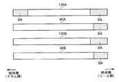
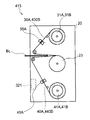
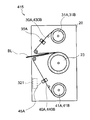
- the conventional temporary storage unit 315 includes a cylindrical drum 23 and a single tape running system 27A.
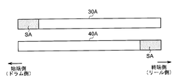
- the tape running system 27A includes an outer tape 30A and an inner tape 40A made of a transparent resin material, and an outer reel 31A and an inner reel 41A around which these are wound.
- the outer tape 30 ⁇ / b> A and the inner tape 40 ⁇ / b> A are fixed so that the end portions are fixed to the outer reel 31 ⁇ / b> A and the inner reel 41 ⁇ / b> A, respectively, and the start ends are overlapped with the peripheral side surface of the drum 23.
- the drum 23 is rotated in the winding direction R1 while the banknote BL is sandwiched between the outer tape 30A and the inner tape 40A, whereby the banknote BL is removed from the outer tape 30A and the inner tape 40A. It can be wound around the peripheral side surface of the drum 23 together with the inner tape 40A.
- the banknotes BL are sequentially discharged by rotating the drum 23 in the rewinding direction R2 while winding the outer tape 30A and the inner tape 40A around the outer reel 31A and the inner reel 41A, respectively. can do.
- light shielding areas SA for blocking light are formed on the start side (drum side) of the outer tape 30A and the end side (reel side) of the inner tape 40A, respectively.
- the temporary storage unit 315 generates a light reception signal of “bright” level corresponding to the transparent portion or “dark” level corresponding to the light shielding area SA by the tape sensor 35A and the tape sensor 45A that irradiates and receives the detection light.
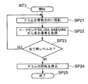
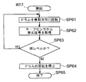
- control unit 321 of the temporary storage unit 315 executes the winding processing procedure RT7 shown in FIG. 21, moves to step SP61, rotates the drum 23 in the winding direction R1, and then performs the next step.
- SP62 a light reception signal is acquired from the tape sensor 45A.
- control unit 321 proceeds to step SP63, and returns to step SP61 again if the light reception signal is at the “bright” level, and moves to next step SP64 if the received light signal is at the “dark” level, and stops the rotation of the drum 23. Further, the process proceeds to step SP65, and the winding processing procedure RT7 is terminated.
- the temporary storage unit 315 can stop the drum 23 before completely winding each tape from each reel, and can prevent damage to the outer tape 30A and the inner tape 40A due to excessive tension. it can.
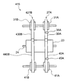
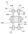
- the tape travel system corresponding to the tape travel system 27A. It is conceivable to configure a temporary holding unit 415 to which 427B is added.
- the temporary storage unit 415 four tapes of two systems are similarly wound up by the cylindrical drum 23. Therefore, when the leading end portion or the ending portion of one tape is detected, the same applies to the other tapes. It is conceivable that it is considered to be in the tip portion or the end portion.
- the light shielding area SA is not provided. It has an outer tape 430B and an inner tape 440B, and the tape sensor is omitted.
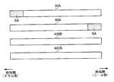
- the temporary storage unit 415 includes the banknote BL wound around the peripheral side surface of the drum 23 when the banknote BL having a fold or a fold is wound around the drum 23 as compared with the case where the flat banknote BL is wound.
- the apparent outer diameter (hereinafter referred to as the winding diameter) increases, so to speak.
- the temporary storage unit 415 is wound around the drum as shown in FIG. 24A and FIG. 24B when the wrinkles or folds are biased to one side in the longitudinal direction of the bill BL, and the winding diameter (swelling) of the drum is also biased.
- the length of the tape is different for each tape running system.
- the outer tape 430B and the inner tape are detected before the tape sensor 45A detects the light shielding area SA at the end portion of the inner tape 40A.
- the tape sensor 45A detects the light shielding area SA at the end portion of the inner tape 40A.
- 440B may reach the end portion, in other words, it may not be possible to detect that the outer tape 440A and the inner tape 440B have reached the end portion.
- the temporary holding unit 415 has a problem that excessive tension is applied to the outer tape 440A and the inner tape 440B to damage these tapes, and the operation must be stopped.
- the present invention has been made in consideration of the above points, and intends to propose a medium processing apparatus that can operate stably.
- a drum that is cylindrical and rotates around the central axis, and a predetermined length in the longitudinal direction, which is drawn from a pre-wound inner reel, the drum A plurality of inner tapes that are wound around the peripheral side surface of the drum at two or more different locations in the axial direction along the central axis of the drum, and a predetermined length in the longitudinal direction, and the inner tape is drawn from a pre-wound outer reel.
- a plurality of outer tapes wound around a peripheral side surface of the drum together with the inner tape and the medium with a paper sheet medium interposed therebetween, and an end on the drum side in at least one of the plurality of inner tapes or the plurality of outer tapes Are formed at the start end, which is a portion, and at the end, which is the end on the inner reel side or the outer reel side, in all inner tapes or all outer tapes, Among the different areas having different properties and the inner tape and the outer tape in which the different areas are formed at the start or end, a plurality of physical properties are detected at a tape position between the drum, the inner reel, and the outer reel. And a control unit for controlling the rotation of the drum based on the detection results of the plurality of detection units.
- the detection unit provided in each tape running system can detect the difference area and reliably detect the arrival of the terminal part, so that the drum rotation is stopped to prevent damage to the inner tape and the outer tape. be able to.
- the detection unit provided in each tape running system can detect the difference area and reliably detect the arrival of the terminal part, so that the drum rotation is stopped and the inner tape and the outer tape are damaged. Can be prevented.
- the present invention can realize a medium processing apparatus that can operate stably.
- the automatic teller machine 1 is configured with a box-shaped housing 2 as the center, and is installed in a financial institution, for example, for a deposit transaction or a withdrawal transaction with a customer. To deal with cash.
- the case 2 has a shape in which a bill BL is inserted or a touch panel is easily operated with a customer facing the front side, that is, a portion extending from the upper part of the front surface to the upper surface is cut off obliquely. In this portion, the customer service section 3 is provided.
- the customer service section 3 directly exchanges cash, bankbooks, etc. with the customer, and is also configured to notify transaction information and accept operation instructions.
- Card entry / exit 4 is a portion where various cards such as cash cards are inserted or ejected.
- a card processing unit (not shown) for reading account numbers and the like magnetically recorded on various cards is provided on the back side of the card slot 4.
- the deposit / withdrawal port 5 is a portion where the bill BL to be deposited by the customer is inserted and the bill BL to be dispensed to the customer is discharged.
- the deposit / withdrawal port 5 is opened or closed by driving a shutter.
- banknote BL is comprised, for example with the rectangular paper.
- the operation display unit 6 is integrated with an LCD (Liquid Crystal Display) for displaying an operation screen at the time of transaction and a touch panel for selecting a transaction type, inputting a personal identification number, transaction amount, and the like.
- LCD Liquid Crystal Display
- the numeric keypad 7 is a physical key that accepts input of numbers such as “0” to “9”, and is used when inputting a password or transaction amount.
- the receipt issuing port 8 is a part for issuing a receipt on which transaction details are printed at the end of transaction processing.
- a receipt processing unit (not shown) for printing transaction contents and the like on the receipt is provided on the back side of the receipt issuing port 8.
- the side of the automated teller machine 1 facing the customer is the front side, the opposite is the rear side, the left and right are the left side and the right side as viewed from the customer facing the front side, and the upper side and the lower side. Is defined and explained.
- a main control unit 9 that performs overall control of the entire automatic teller machine 1, a banknote depositing and dispensing machine 10 that performs various processes related to the banknote BL, and the like.
- the main control unit 9 is mainly configured by a CPU (Central Processing Unit) (not shown), and by reading and executing a predetermined program from a ROM, a flash memory, etc. (not shown), various transactions such as a deposit transaction and a withdrawal transaction are performed. It is made to perform the process.
- a CPU Central Processing Unit
- ROM Read Only Memory
- flash memory etc.
- the main control unit 9 includes a storage unit 9A including a RAM (Random Access Memory), a hard disk drive, a flash memory, and the like, and stores various information in the storage unit 9A.
- a storage unit 9A including a RAM (Random Access Memory), a hard disk drive, a flash memory, and the like, and stores various information in the storage unit 9A.
- the housing 2 is constituted by a door that can be opened and closed on a part of its side such as the front side and the rear side. That is, the housing
- the housing 2 can be easily operated on each part by opening the doors as necessary during maintenance work performed by an operator or the like.
- the banknote depositing and dispensing machine 10 has a configuration in which a plurality of parts that perform various processes related to the banknote BL are combined. Each part of the bill depositing / dispensing machine 10 is controlled by the bill control unit 11.
- the banknote control unit 11 is configured around a CPU (not shown) as in the case of the main control unit 9, and determines a conveyance destination of the banknote BL by reading and executing a predetermined program from a ROM, flash memory, etc. (not shown). Various processing such as processing to perform is performed.
- the banknote control part 11 has 11 A (FIG. 1) memory
- the bill control unit 11 receives a predetermined operation input via the operation display unit 6, and then opens the shutter of the deposit / withdrawal port 5 to within the deposit / withdrawal unit 12. A bill BL is inserted.
- the deposit / withdrawal unit 12 closes the shutter of the deposit / withdrawal port 5, takes out the bill BL one by one from the container 12 ⁇ / b> A, and delivers it to the transport unit 13.
- the conveyance part 13 advances the banknote BL comprised in rectangular paper sheet shape along a short side direction, and conveys it to the discrimination part 14.
- the discriminating unit 14 discriminates the denomination and authenticity of the bill BL, the degree of damage, etc. using the optical element, the magnetic detection element, etc. while conveying the bill BL in the inside, and bill control is performed on the discrimination result. Notification to the unit 11. In response to this, the banknote control unit 11 determines the transport destination of the banknote BL based on the acquired discrimination result.
- the transport unit 13 temporarily holds the banknote BL discriminated as a normal banknote by the discriminating unit 14 by temporarily transporting the banknote BL to the temporary storage unit 15, and deposits / withdraws rejected banknotes identified as not to be traded. It is transported to the section 12 and returned to the customer.
- the banknote control unit 11 allows the customer to confirm the deposit amount via the operation display unit 6, transports the banknote BL held in the temporary storage unit 15 to the discrimination unit 14 by the transport unit 13, and denomination and damage thereof. The degree of such as is discriminated, and the discrimination result is acquired.
- banknote control part 11 will convey this to the rejection cassette 16 by the conveyance part 13 as the banknote BL which should not be reused if the extent of damage of the banknote BL is large, and if this is small, this will be stored.
- a bill BL to be reused is transported by the transport unit 13 and stored in a bill cassette 17 corresponding to the denomination.
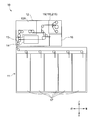
- the temporary storage unit 15 has a configuration in which each component is attached to the frame 20.
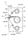
- 3A and 3B schematically show a right side view and a rear view of the temporary storage unit 15, respectively, and some components such as a motor and a gear are omitted for convenience of explanation.
- the temporary holding unit 15 is controlled by the control unit 21 as a whole. Similar to the main control unit 9 and the bill control unit 11 (FIG. 1), the control unit 21 is configured around a CPU (not shown), and in cooperation with the bill control unit 11 and the like, a ROM, a flash memory, etc. not shown. By reading and executing a predetermined program from the above, various processes such as drum rotation and tape running control are performed.
- the control unit 21 has a storage unit such as a RAM and a flash memory, and stores various information in the storage unit.
- a cylindrical drum 23 is provided near the center of the temporary holding unit 15 in the frame 20.
- the drum 23 is attached so as to be able to rotate in the winding direction R1 or the rewinding direction R2 around the rotation shaft 24 along the left-right direction. It is made to be transmitted.
- the drum rotation detection unit 25 detects the rotation state such as the rotation direction and speed of the drum 23 and notifies the control unit 21 of this as a rotation signal so that the control unit 21 stores the immediately preceding rotation direction. Has been made.
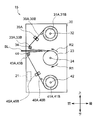
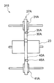
- tape running systems 27A and 27B which are configured in substantially the same manner and are different from each other in part, are provided on the left and right sides, respectively.
- tape running system 27A on the right side.
- the outer tape 30A and the inner tape 40A are both formed into a thin film by a resin material having high light transmittance.
- the outer tape 30A and the inner tape 40A are both sufficiently long in the longitudinal direction, for example, 30 [m], while the length in the short direction (that is, the tape width) is, for example, 20 [mm]. It is sufficiently shorter than the long side of the bill BL.
- the outer reel 31 ⁇ / b> A is formed in a bobbin shape, and is provided on the upper side of the drum 23 so as to rotate around a rotation shaft 32 parallel to the rotation shaft 24 of the drum 23.
- the outer tape 30A is wound around the outer reel 31A after one end of the outer tape 30A is fixed to the peripheral side surface.
- a pulley 33 ⁇ / b> A is provided on the front side of the drum 23.
- the pulley 33A is formed in a columnar shape and is inserted through a shaft 34 parallel to the rotating shaft 24 of the drum 23, and can rotate freely around the shaft 34.
- the outer tape 30A wound around the outer reel 31A is pulled out from the outermost periphery of the outer reel 31A to the front and lower side, and is folded back in the backward direction via the pulley 33A. It is fixed to the peripheral side.
- the outer reel 31A is urged in a direction to wind up the outer tape 30A by a torque limiter (not shown) so that the outer tape 30A is always given a predetermined tension.
- the inner reel 41A is configured in the same form as the outer reel 31A.
- the inner reel 41A is below the outer reel 31A, that is, below the drum 23, with a rotating shaft 42 parallel to the rotating shaft 24 of the drum 23 as a center. It is provided so that it can rotate.
- the inner tape 41A is wound around the inner reel 41A after one end of the inner tape 40A is fixed to the peripheral side surface.
- the winding direction of the inner tape 40A on the inner reel 41A is opposite to the winding direction of the outer tape 30A on the outer reel 31A.
- a pulley 43A is provided in front of the inner reel 41A and below the pulley 33A.
- the pulley 43A is formed in a columnar shape similar to the pulley 33A and is inserted through a shaft 44 parallel to the rotation shaft 24 of the drum 23 so that the pulley 43A can freely rotate around the shaft 44. .
- the inner tape 40A wound around the inner reel 41A is pulled forward from the outermost periphery of the inner reel 41A to the front and upward, and then folded back in the backward direction via the pulley 43A. It is fixed to the side.
- the inner reel 41A is urged in a direction to wind up the inner tape 40A by a torque limiter (not shown) so that the inner tape 40A is always given a predetermined tension. .
- the tape running system 27B on the left side includes an outer tape 30B, an outer reel 31B, an outer tape 30A, an outer reel 31A, a pulley 33A, an inner tape 40A, an inner reel 41A, and a pulley 43A that are configured in the same manner as the tape running system 27A.
- a pulley 33B, an inner tape 40B, an inner reel 41B, and a pulley 43B are provided.
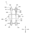
- the temporary storage unit 15 winds the inner tape 40A and the outer tape 30A on the circumferential side surface and the inner tape 40B and the outer tape 30B. .
- the temporary storage unit 15 sandwiches the banknote BL between the inner tapes 40A and 40B and the outer tapes 30A and 30B, the banknote BL is drummed together with the inner tapes 40A and 40B and the outer tapes 30A and 30B. Can be wrapped around
- the temporary storage unit 15 is configured to wind the bill BL around the peripheral side surface of the drum 23 by running four tapes (the outer tapes 30A and 30B and the inner tapes 40A and 40B).
- a tape sensor 35A serving as a detection unit is disposed at the nearest position (hereinafter referred to as a tape position).
- the tape sensor 35A opposes a light emitting unit that emits detection light having a predetermined wavelength and a light receiving unit that receives the detection light so that the outer tape 30A is sandwiched from both sides.
- the tape sensor 35A emits detection light from the light emitting unit, and a portion of the detection light that has passed through the outer tape 30A is received by the light receiving unit, and a light reception signal corresponding to the brightness is generated. 21 is sent out.
- the tape sensor 35A generates a light reception signal corresponding to the ratio of transmitting the detection light at the tape position of the outer tape 30A (that is, the irradiation position of the detection light), and sends it to the control unit 21.
- the control unit 21 determines a “bright” level if the received light signal acquired from the tape sensor 35A is equal to or greater than a predetermined threshold value, and determines a “dark” level if the received light signal is less than the predetermined threshold value. Yes. That is, the determination result obtained in the control unit 21 at this time is a value obtained by binarizing the light transmittance of the outer tape 30A at the position of the tape sensor 35A at this time point to the “light” level or the “dark” level. Become.
- the tape running system 27A has a position where the inner tape 40A is passed between the inner reel 41A and the pulley 43A, that is, in the immediate vicinity of the outermost peripheral portion of the inner tape 40A wound around the inner reel 41A.
- a tape sensor 45A having the same configuration as the tape sensor 35A is disposed.
- the tape running system 27B is provided with a tape sensor 45B corresponding to the inner tape 40B, but is not provided with a tape sensor corresponding to the outer tape 30B.
- the tape sensor 35A is provided only in one tape running system 27A for the outer tape 30 (30A and 30B), and both tape running systems 27A are provided for the inner tape 40 (40A and 40B). And 27B are provided with tape sensors 45A and 45B, respectively.
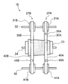
- the outer tape 30 ⁇ / b> A is provided with a tape sensor at a starting end portion (hereinafter referred to as a starting end portion) fixed to the drum 23, similar to the outer tape 30 ⁇ / b> A in the conventional temporary holding portion 415.
- a light blocking area SA that blocks the detection light of 35A is formed.
- the outer tape 30A transmits the detection light of the tape sensor 35A in a transparent portion where the light shielding area SA is not formed, but blocks the detection light in the light shielding area SA.
- the tape sensor 35A increases the signal level of the received light signal because the detection light is transmitted if the tape position of the outer tape 30A is the intermediate portion (the portion that is neither the start end portion nor the end portion) or the end portion. In this case, the detection light is blocked by the light shielding area SA, so that the signal level of the received light signal is lowered.
- the threshold value compared with the light reception signal in the control unit 21 is appropriately selected so that the signal level lowered by the light shielding area SA is set to the “dark” level, and the signal level higher than that is set to the “light” level. Has been.
- a light-shielding area SA is formed in a terminal portion (hereinafter referred to as a terminal portion) fixed to the inner reel 41A.
- the tape sensor 45A raises the signal level of the received light signal because the detection light is transmitted if the tape position of the inner tape 40A is the start end portion or the intermediate portion. Since this is cut off, the signal level of the received light signal is lowered.
- the inner tape 40B of the tape running system 27B is different from the conventional inner tape 440B in that a light-shielding area SA is formed on the end side, like the inner tape 40A.
- the light shielding area SA is not formed at any place, as in the conventional outer tape 430B.
- the temporary storage unit 15 has a configuration in which a tape sensor 45B is added and a light shielding area SA is added to the end side of the inner tape 40B, compared to the conventional temporary storage unit 415 (FIGS. 22A and 22B). It has become.
- the light-shielding area SA is formed only on the outer tape 30A of the tape running system 27A, that is, only on the outer tape 30 in one tape running system 27, with respect to the starting end side of each tape. .
- the light-shielding areas SA are formed on both the inner tapes 40A and 40B, that is, on the inner tapes 40 in all the tape running systems 27, on the end side of each tape.
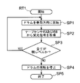
- control unit 21 of the temporary storage unit 15 controls the rotation of the drum 23 and the like according to the flowchart shown in FIG.
- control part 21 of the temporary storage part 15 receives the instruction
- step SP1 the control unit 21 rotates the drum 23 in the winding direction R1, and proceeds to the next step SP2.
- the control unit 21 rotates the drum 23 by a predetermined angle by controlling a stepping motor (not shown).
- step SP2 the control unit 21 acquires the light reception signals from the tape sensors 45A and 45B, and proceeds to the next step SP3.
- step SP3 the control unit 21 determines whether or not all of the acquired light reception signals are at the “bright” level.
- a positive result is obtained, it indicates that none of the inner tapes 40A and 40B has reached the end portion. That is, even if the temporary storage unit 15 continues to rotate the drum 23 in the winding direction R1, there is no possibility of damaging each tape. For this reason, the control part 21 returns to step SP1 again and continues the rotation of the drum 23.
- step SP3 if a negative result is obtained in step SP3, it indicates that the tape position in at least one of the inner tapes 40A and 40B has reached the end portion where the light shielding area SA is formed. That is, in the temporary storage unit 15, if the rotation of the drum 23 in the winding direction R ⁇ b> 1 is continued, each tape may be damaged. Therefore, the control unit 21 proceeds to the next step SP4.
- step SP4 after stopping the rotation of the drum 23, the control unit 21 moves to the next step SP5 and ends the winding processing procedure RT1.
- control unit 21 of the temporary storage unit 15 rotates the drum 23 in the winding direction R1
- it monitors at least one of the inner tapes 40A and 40B by monitoring the light reception signals of both the tape sensors 45A and 45B. The rotation is stopped when the tape position reaches the end portion.
- the inner tapes 40A and 40B are arranged so that the light shielding area SA reaches the position of the tape sensors 45A and 45B before the inner tapes 40A and 40B wound around the inner reels 41A and 41B are all pulled out. The length from the end is properly determined.
- the temporary holding unit 15 when the temporary holding unit 15 receives an instruction to discharge the banknote BL held inside to the outside from the banknote control unit 11 (FIG. 2) or the like, the temporary holding unit 15 starts the rewinding processing procedure RT2 and proceeds to step SP11.
- step SP11 the control unit 21 rotates the drum 23 in the rewinding direction R2, and proceeds to the next step SP12.
- the control unit 21 acquires a light reception signal from the tape sensor 35A, and proceeds to the next step SP13.
- step SP13 the control unit 21 determines whether or not the acquired light reception signal is at “bright” level. If a positive result is obtained here, it indicates that the tape position of the outer tape 30A has not reached the end portion. That is, even if the temporary storage unit 15 continues to rotate the drum 23 in the rewind direction R2, there is no possibility of damaging each tape. For this reason, the control part 21 returns to step SP11 again and continues the rotation of the drum 23.
- step SP13 if a negative result is obtained in step SP13, it indicates that the tape position of the outer tape 30A has reached the starting end where the light shielding area SA is formed. That is, in the temporary storage unit 15, if the rotation of the drum 23 in the rewind direction R2 is continued, each tape may be damaged. Therefore, the control unit 21 proceeds to the next step SP14.
- step SP14 after stopping the rotation of the drum 23, the control unit 21 proceeds to the next step SP15 and ends the rewinding processing procedure RT2.
- control unit 21 of the temporary storage unit 15 rotates the drum 23 in the rewind direction R2
- the time point when the tape position of the outer tape 30A reaches the start end It is designed to stop the rotation.
- the length of the outer tape 30A from the start end in the light shielding area SA is such that the light shielding area SA reaches the position of the tape sensor 35A before all the outer tape 30A wound around the peripheral side surface of the drum 23 is rewound. It is properly defined.
- the temporary storage unit 15 is provided with a light-shielding area SA at the start end of only one outer tape 30A, and this is detected by the tape sensor 35A.
- the temporary storage unit 15 is provided with the tape sensor 45B of the tape running system 27B in addition to the tape sensor 45A of the tape running system 27A, and a light shielding region at the end of the inner tape 40B. SA was provided.
- control unit 21 of the temporary storage unit 15 monitors the light reception signals of the tape sensors 45A and 45B during the winding operation of the drum 23, and terminates when at least one of them becomes the “dark” level and detects the light shielding area SA. And the rotation of the drum 23 is stopped.
- the temporary storage unit 15 can stop the winding operation of the drum 23 when any of the inner tapes 40A or 40B reaches the end portion during the winding operation of the drum 23, and each tape is overloaded. Damage due to the application of a proper tension can be prevented in advance.
- the winding of the drum 23 is caused by wrinkles or the like of the bills BL as in the case of the conventional temporary storage unit 415. It is conceivable that the diameter (the apparent outer diameter including the wound banknote BL) is different between the tape running systems 27A and 27B.
- the temporary holding portion 15 is the point where the inner tape 40B having the larger winding diameter (in this case, the inner tape 40B) has reached the end portion first, and the inner tape 40B is detected by the tape sensor 45B. Therefore, the rotation of the drum 23 can be reliably stopped.
- the temporary storage unit 15 is provided with a tape sensor 45B equivalent to the tape sensor 45A, as compared with the conventional temporary storage unit 415, and forms a light shielding area SA similar to that of the internal tape 40A at the end of the internal tape 40B. Furthermore, it is only necessary to change a part of the winding process procedure of the control unit 21, and it is possible to extremely suppress an increase in parts and a complicated manufacturing process due to the change in configuration.
- the temporary storage unit 15 is provided with the tape sensors 45A and 45B in both the tape running systems 27A and 27B and at the end of the inner tapes 40A and 40B, the light shielding area SA. Were provided. Then, the control unit 21 of the temporary storage unit 15 monitors the light reception signals of the tape sensors 45A and 45B during the winding operation of the drum 23, and when one of them becomes the “dark” level and detects the light shielding area SA, The rotation of the drum 23 was stopped. For this reason, the temporary storage unit 15 can stop the winding operation of the drum 23 when either the inner tape 40A or 40B reaches the terminal portion first during the winding operation of the drum 23. Damage due to excessive tension can be prevented in advance.
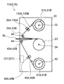
- the automatic teller machine 101 (FIG. 1) according to the second embodiment is different from the automatic teller machine 1 according to the first embodiment in that it has a temporary holding unit 115 instead of the temporary holding unit 15. However, the other parts are configured similarly.
- the temporary storage unit 115 is compared with the temporary storage unit 15 according to the first embodiment.
- the other components are configured in the same manner except that the control unit 121 instead of the tape running system 27A and the tape running system 27B, the tape running system 127A, and the tape running system 127B are provided.
- control unit 121 includes a CPU, a storage unit, and the like (not shown), and performs various processes such as control of drum rotation and tape running.
- a difference is that a winding processing procedure RT3 (described later) instead of the procedure RT1 is executed. *
- the tape traveling system 127A is different from the tape traveling system 27A in that it has an outer tape 130A in place of the outer tape 30A, but the other parts are configured similarly.
- the tape running system 127B is different from the tape running system 27B in that it has an outer tape 130B instead of the outer tape 30B and a tape sensor 135B similar to the tape sensor 35A, but the other parts are the same. It is configured.
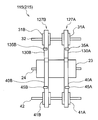
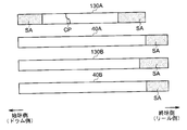
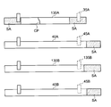
- the outer tapes 130A and 130B have the same reference numerals as those in FIG. 4, and a light-shielding area SA is formed at the end portion as in the case of the inner tapes 40A and 40B.
- the outer tapes 130A and 130B end the light shielding area SA so that the light shielding area SA reaches the position of the tape sensors 35A and 135B before the outer tapes 130A and 130B wound around the outer reels 31A and 31B are all pulled out. The length from is properly determined.
- the path length of the outer tapes 130A and 130B from the outer reels 31A and 31B to the tape sensors 35A and 135B, and the path length of the inner tapes 40A and 40B from the inner reels 41A and 41B to the tape sensors 45A and 45B. are different from each other. Therefore, the lengths of the outer tapes 130A and 130B from the end of the light shielding area SA are different from those of the inner tapes 40A and 40B.
- controller 121 controls the rotation and the like of the drum 23 according to the flowchart shown in FIG. 10 corresponding to FIG.
- control part 121 of the temporary storage part 115 receives the instruction
- step SP21 the control unit 121 rotates the drum 23 in the winding direction R1 as in step SP1, and proceeds to the next step SP22.
- step SP22 the control unit 121 acquires the light reception signals from all the tape sensors, that is, the tape sensors 35A and 135B and the tape sensors 45A and 45B, and proceeds to the next step SP23.
- step SP23 the control unit 121 determines whether or not all of the acquired light reception signals are at the “bright” level. If a positive result is obtained here, it means that none of the outer tapes 130A and 130B and the inner tapes 40A and 40B has reached the end portion. That is, even if the temporary storage unit 115 continues to rotate the drum 23 in the winding direction R1, there is no possibility of damaging each tape. Therefore, the control unit 121 returns to step SP21 again to continue the rotation of the drum 23.
- step SP23 if a negative result is obtained in step SP23, it indicates that the position of at least one of the outer tapes 130A and 130B and the inner tapes 40A and 40B has reached the end. That is, in the temporary storage unit 115, if the rotation of the drum 23 in the winding direction R1 is continued, each tape may be damaged. Therefore, the control unit 121 proceeds to the next step SP24.
- step SP24 the controller 121 stops the rotation of the drum 23 in the same manner as in step SP4, and then proceeds to the next step SP25 to end the winding processing procedure RT3.
- the external tapes 130A and 130B are monitored by monitoring the light reception signals of the tape sensors 35A and 135B and the tape sensors 45A and 45B. The rotation is stopped when at least one of the inner tapes 40A and 40B reaches the end portion.
- the temporary storage unit 115 is provided with the tape sensor 135B similar to the tape sensor 35A in the tape running system 127B, and the light shielding region SA at the end portions of the outer tapes 130A and 130B. It was.
- the control unit 121 of the temporary storage unit 115 monitors the light reception signals of the tape sensors 35A and 135B and the tape sensors 45A and 45B during the winding operation of the drum 23, and at least one of them becomes the “dark” level and the light shielding area SA. Is detected, the drum 23 is determined to have reached the end, and the rotation of the drum 23 is stopped.
- the temporary storage unit 115 stops the winding operation of the drum 23 when at least one tape position of the outer tapes 130A and 130B and the inner tape 40A or 40B reaches the end portion during the winding operation of the drum 23. Any tape can be prevented from being damaged due to an excessive tension applied.
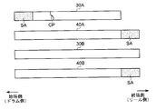
- the banknote BL interferes with surrounding parts at the time of conveyance or winding of the banknote BL having folding folds, hooks, etc., and causes clogging, etc. It can happen that it is cut. In addition, there is a possibility that the maintenance worker may accidentally cut the tape during the maintenance work.
- the temporary holding unit 115 is originally replaced with a new tape. However, if it takes time to obtain a new tape, etc., the remaining part of the tape is cut off as an emergency measure. Are joined to each other at the joining point CP, the tape may be cut off.
- the outer tape 30 ⁇ / b> A in which the light-shielding area SA is not formed at the end portion is cut off in the temporary storage unit 15 in the first embodiment.
- the outer tape 30A reaches the terminal portion before the light blocking area SA of the inner tape 40A or 40B is detected by the tape sensor 45A or 45B, so that the operation is poor. And excessive tension may be applied to the outer tape 30A.
- the temporary storage unit 115 even if the winding operation is performed in a state where the outer tape 130A is cut off, the light shielding area SA formed at the terminal portion of the outer tape 130A is removed.
- the rotation of the drum 23 can be stopped by detection by the tape sensor 35A.
- a light-shielding area SA is provided at the terminal portion of all the tapes (the outer tapes 130A and 130B and the inner tapes 40A and 40B), and the tape sensors (tape sensors 35A, 135B, 45A and 45B), whichever tape is cut down, detects when the shortest tape first reaches the end, and stops rotation of the drum 23 to cause malfunction. It is possible to prevent excessive tension from being applied to the tape and the tape.
- the temporary storage unit 115 can achieve the same effects as the temporary storage unit 15 according to the first embodiment in other respects.
- the temporary storage unit 115 is provided with the tape sensors 35A, 135B, 45A, and 45B, and the light shielding region at the end portions of the outer tapes 130A and 130B and the inner tapes 40A and 40B. SA was provided. Then, the control unit 121 of the temporary storage unit 115 monitors the light reception signals of the tape sensors 35A, 135B, 45A, and 45B during the winding operation of the drum 23, and detects one of the “dark” level and the light shielding area SA. At that time, the rotation of the drum 23 was stopped.
- the temporary storage unit 115 immediately stops the winding operation of the drum 23 when any of the outer tapes 130A and 130B and the inner tape 40A or 40B reaches the end portion first during the winding operation of the drum 23. It is possible to prevent damage due to excessive tension applied to each tape.
- the automatic teller machine 201 (FIG. 1) according to the third embodiment is different from the automatic teller machine 101 according to the second embodiment in that it has a temporary holding unit 215 instead of the temporary holding unit 115.
- the other parts are configured similarly.
- the temporary storage unit 215 differs from the temporary storage unit 115 according to the second embodiment in that it has a control unit 221 that replaces the control unit 121, but the other parts are configured in the same manner.
- control unit 221 includes a CPU, a storage unit, and the like (not shown), and performs various processes such as control on drum rotation and tape running, but will be described later.
- a difference is that a position determination processing procedure RT4 and a winding processing procedure RT5 (described later) instead of the winding processing procedure RT3 in the second embodiment are executed.
- the light-shielding area SA is formed at the end of all the tapes (the outer tapes 130A and 130B and the inner tapes 40A and 40B), and the start end of the outer tape 130A. Also, a light shielding area SA is formed (FIG. 9).
- the tape position is not always the start end, and only the outer tape 30A is earlier than other tapes because of the possibility of being the end, that is, the tape length variation or the like. The possibility of reaching the end may also be considered.
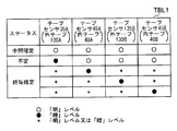
- control unit 221 does not immediately determine the tape position based on the light reception signals obtained from the respective tape sensors (35A, 135B, 45A and 45B), but first displays a “status” indicating a state that can be determined only from the light reception signals. It was classified into three types, and the tape position was finally determined based on this “status”.
- control unit 221 selects one of “intermediate finalized state”, “end finalized state”, and “undefined state” based on the four received light signals from the tape sensors. And store the status.
- control unit 221 determines that the tape position is not the start end portion or the end portion but the intermediate portion.
- control unit 221 cannot determine whether the tape position is the start end portion or the end end portion, and thus sets the “undefined state”.
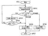
- control unit 221 immediately after the automatic teller machine 201 is turned on and the temporary holding unit 215 is activated, the control unit 221 can determine the status, but cannot determine the tape position particularly when the state is indefinite. Therefore, the control unit 221 executes the flowchart shown in FIG. 14 immediately after the temporary holding unit 215 is activated.
- step SP31 the control unit 221 acquires a light reception signal from each tape sensor, determines whether each is a “bright” level or a “dark” level, and then proceeds to the next step SP32.
- step SP32 the control unit 221 determines the status by comparing the acquired four received light signals with the status table TBL1 (FIG. 13). If the status is “undefined”, the tape position is one of “starting end” and “end”, but at this point it cannot be determined whether it is “starting end” or “end”. Represents that. At this time, the control unit 221 moves to the next step SP33.
- step SP33 the control unit 221 controls the drum 23 to rotate in the winding direction R1 at a low speed, and proceeds to the next step SP34.
- step SP34 the control unit 221 determines whether the drum 23 has actually rotated based on the rotation signal notified from the drum 23. If a positive result is obtained here, this means that the tape has been wound slightly with the rotation of the drum 23, that is, the tape position has changed slightly and the status may have changed. . Therefore, the control unit 221 returns to step SP31 again to reconfirm the status.
- step SP34 if a negative result is obtained in step SP34, it means that the drum 23 did not rotate even if it tried to rotate, that is, one of the tapes reached the end. Therefore, the control unit 221 moves to next step SP35.
- step SP32 when the status is “final terminal finalized state”, it indicates that at least one of the outer tape 130B and the inner tapes 40A and 40B has reached the terminal portion. At this time, the control unit 221 moves to the next step SP35.
- step SP35 the control unit 221 sets the tape position to the end, and then proceeds to step SP37 to end the tape position determination processing procedure RT4 at the time of activation.
- step SP32 If the status is “intermediate confirmed state” in step SP32, the control unit 221 moves to the next step SP36 because each tape is in the intermediate part.
- step SP36 the control unit 221 sets the tape position to the intermediate part, and then proceeds to step SP37 to end the tape position determination processing procedure RT4 at the time of activation.
- control unit 221 determines the tape position by rotating the drum 23 at a low speed in addition to the light reception signal of each tape sensor.
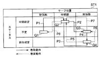
- the temporary holding unit 215 updates the tape position according to the state transition diagram ST1 of FIG. 15 when the winding operation or the rewinding operation is performed after the tape position is determined.
- the state transition diagram ST1 represents the status in the vertical direction and the tape position in the horizontal direction, and represents a combination of both by a transition mode Q represented by a rectangle.
- a solid line arrow indicates a winding operation, which is a rightward or vertical transition in the figure.
- the broken-line arrow represents the rewinding operation, and transitions to the left or up and down in the figure.
- control unit 221 of the temporary storage unit 215 has the status “undefined” when the tape position is “starting end”, and enters the transition mode Q1. If the control unit 221 performs a winding operation and the status becomes “intermediate confirmed state”, the control unit 221 transits to the transition mode Q2 along the arrow P1 and sets the tape position to “intermediate part”.
- control unit 221 when the control unit 221 further performs a winding operation and the status becomes “indeterminate state” or “termination final state”, the control unit 221 transits to the transition mode Q3 or Q4 along the arrow P2 or P3, and changes the tape position to “termination”. Part ". Further, when the control unit 221 performs the winding operation in the transition mode Q3 in which the status is “indeterminate state” and enters the “termination final state”, the control unit 221 transitions to the transition mode Q4 along the arrow P4.
- the controller 221 when the controller 221 performs the rewinding operation in the transition mode Q4 in which the status is “termination final state” and the tape position is “termination part”, the transition occurs along the arrow P5 if the status becomes “intermediate finalization state”. Moving to mode Q2, the tape position is set to “intermediate part”, and when the status becomes “indeterminate state”, the process moves to transition mode Q3 along the arrow P6 and the tape position is kept at “end part”. Further, the control unit 221 performs a rewinding operation in the transition mode Q3, and when the status becomes the “intermediate confirmed state”, the control unit 221 transitions to the transition mode Q2 along the arrow P7 and sets the tape position to “intermediate part”.
- control unit 221 transitions to the transition mode Q1 along the arrow P8 and sets the tape position to the “starting end”.
- the temporary storage unit 215 changes the tape position by transitioning to the new transition mode Q according to the immediately preceding transition mode Q and the type of operation (winding operation or rewinding operation) in the state transition diagram ST1. It has been made to update.
- the temporary holding unit 215 performs a winding operation or a rewinding operation while updating the tape position according to the state transition diagram ST1.
- control unit 221 receives an instruction to hold the banknote BL from the banknote control unit 11 (FIG. 2) or the like in a state where the tape position is found to be the starting end part or the intermediate part, it corresponds to FIG. 5.
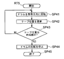
- the winding processing procedure RT5 shown in FIG. 16 is started and the process proceeds to step SP41.
- step SP41 the control unit 221 rotates the drum in the winding direction as in step SP1, and proceeds to the next step SP42.
- step SP42 the control unit 221 updates the tape position by appropriately shifting the transition mode Q according to the state transition diagram ST1, and proceeds to the next step SP43.
- step SP43 the control unit 221 determines whether or not the updated tape position is the end portion. If a negative result is obtained, the rotation of the drum 23 is stopped because the tape position is still the start end or the intermediate portion and the tape position is the start end even if the status is “undefined”. This means that it is not necessary to Therefore, the control unit 221 returns to step SP41 and continues the rotation of the drum 23.
- step SP43 if an affirmative result is obtained in step SP43, it indicates that the tape position is determined to be the end even if the obtained status is “undefined”. At this time, the control unit 221 moves to the next step SP44.
- step SP44 the control unit 221 stops the rotation of the drum 23, moves to the next step SP45, and ends the winding processing procedure RT5.
- control part 221 receives the instruction
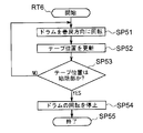
- the rewinding processing procedure RT6 shown in FIG. 17 is started and the process proceeds to step SP51.
- step SP51 the control unit 221 rotates the drum in the rewinding direction as in step SP11, and proceeds to the next step SP52.
- step SP52 as in step SP42, the control unit 221 updates the tape position by appropriately shifting the transition mode Q according to the state transition diagram ST1, and proceeds to the next step SP53.
- step SP53 the control unit 221 determines whether or not the updated tape position is the start end. If a negative result is obtained here, the rotation of the drum 23 is stopped because the tape position is still the terminal part or the intermediate part and the tape position is the terminal part even if the status is “undefined”. This means that it is not necessary to Therefore, the control unit 221 returns to step SP51 and continues the rotation of the drum 23.
- step SP53 if an affirmative result is obtained in step SP53, it indicates that the tape position is determined to be the start end even if the obtained status is “indefinite state”. At this time, the control unit 221 proceeds to the next step SP54.
- step SP54 the control unit 221 stops the rotation of the drum 23, moves to the next step SP55, and ends the rewinding processing procedure RT6.
- the temporary storage unit 215 performs the winding operation and the rewinding operation while updating the tape position according to the state transition diagram ST1, so that the tape position is set to the start end portion or the end position even if the status is “indefinite state”. It is designed so that it can be correctly distinguished from the end portion.
- the temporary holding portion 215 according to the third embodiment is provided at the start end portion of the outer tape 130A, the outer tape 130A and 130B, and the end portion of the inner tape 40A and 40B, as in the second embodiment.
- a light shielding area SA was formed (FIG. 9).
- the temporary storage unit 215 generates a light reception signal corresponding to the light transmittance of each tape by the tape sensors 35A, 135B, 45A, and 45B, and sends it to the control unit 221.
- control unit 221 Based on the light reception signals obtained from the respective tape sensors (35A, 135B, 45A and 45B), the control unit 221 sets the status to “intermediate finalized state”, “end finalized state” or “end” according to the status table TBL1 (FIG. 13). It was decided to be one of “indefinite state”.
- the temporary storage unit 215 sets the “undefined state” in which the tape position is not specified when only the tape sensor 35A is in the “dark” level and the tape position cannot be determined as the start end or the end end. Therefore, it is possible to reliably eliminate the risk of damaging the tape without discriminating it as an erroneous tape position.
- the outer tape 130A is cut off during maintenance work or the like, as shown in FIG. 18, the outer tape is present both at the start end (shown by a solid line) and near the end (shown by a broken line).
- the light shielding area SA is detected only for 130A, the tape sensor 35A becomes “dark” level, and the other tape sensors become “light” level.
- the controller 231 when the controller 221 has just started and cannot determine the previous operation state, the controller 231, by rotating the drum 23 in the winding direction at a low speed, monitors the status change and the rotation of the drum 23, thereby accurately determining the tape position. It can be discriminated as an intermediate part or a terminal part.
- the temporary storage unit 215 transmits a relatively low driving force so as to rotate the drum 23 at a low speed in the winding direction. Therefore, even if the tape is at the end position, the tension applied to the tape is reduced. Since it can suppress, the danger of damaging can be reduced significantly.
- the control unit 221 updates the tape position according to the state transition diagram ST1 (FIG. 15), so that even if the status becomes “indefinite state”, the winding is performed immediately before. Depending on whether the take-up operation or the rewinding operation is performed, it can be correctly specified that the tape position is the end portion or the start end portion.
- the temporary storage unit 215 can use the light shielding area SA having the same optical characteristics at the start end and the end end of the outer tape 130A, and can detect both of them by the tape sensor 35A. For this reason, for example, the temporary storage unit 215 has a significantly simpler configuration than the case where two different types of tape sensors are used while providing regions having different optical characteristics at the start and end portions of the outer tape 130A, for example. Can be
- the temporary storage unit 215 since the temporary storage unit 215 has the same optical characteristics of the light shielding areas SA provided at the start end and the end of the outer tape 130A, only from the signal level of the light reception signal obtained from the tape sensor 35A. In this case, the tape position cannot be accurately determined, but the tape position is specified by considering the change in status when the drum 23 is intentionally rotated in the winding direction R1 or according to the immediately preceding tape position and operation. Can do.
- the temporary storage unit 215 executes the winding processing procedure RT3 (FIG. 10) and the rewinding processing procedure RT2 (FIG. 6), in the vicinity of the end portion (indicated by a broken line in FIG. 18) during the winding operation.
- the winding operation is stopped when the light shielding area SA is detected only in the outer tape 130A.
- the temporary holding unit 215 tries to start the rewinding operation, the light blocking area SA of the outer tape 130A is detected, so that the rewinding operation is stopped immediately and each tape cannot be rewound. was there.
- the tape position is updated according to the state transition diagram ST1, so even if the status becomes “undefined” during the rewinding operation, the transition where the tape position is in the middle If the winding operation is not performed from mode Q2, the tape position does not shift to the transition mode Q1, which is the starting end, and therefore it is possible to correctly determine whether it is the starting end or the end based on the immediately preceding operation.
- the temporary holding unit 215 can stop the rotation only when the tape position reaches the start end by executing the rewinding processing procedure RT6 using the tape position update according to the state transition diagram ST1. Until then, the tape can be properly rewound onto the reel.
- the temporary storage unit 215 can achieve the same effects as the temporary storage unit 115 according to the second embodiment in other respects.
- the temporary storage unit 215 is provided with the tape sensors 35A, 135B, 45A, and 45B, and has a light shielding area at the end portions of the outer tapes 130A and 130B and the inner tapes 40A and 40B. SA was provided. Then, the control unit 221 of the temporary storage unit 215 determines the status as “intermediate finalized state”, “end finalized state”, or “undefined state” based on the light reception signals of the tape sensors 35A, 135B, 45A, and 45B. Then, after determining the tape position, the tape position is updated according to the state transition diagram ST1 according to the operation.
- the temporary holding unit 215 can correctly determine the tape position while providing the same light-shielding area SA at the start end and the end of the outer tape 130A, so when it reaches the end during the winding operation, Alternatively, the drums 23 can be stopped when they reach the start end during the rewinding operation, and damage due to excessive tension applied to each tape can be prevented.
- the start end portion may be detected by the inner tape 40A and the end portion may be detected by the outer tapes 30A and 30B.
- the second and third embodiments are not limited to this.
- the start end portion may be detected by the inner tape 40A and the end portion may be detected by the outer tapes 30A and 30B.
- the second and third embodiments are not limited to this.
- the present invention is not limited to this.
- the light shielding area SA may be provided at the start end of two or more tapes, for example, the light shielding area SA may be provided at the start end of the outer tape 130B.
- the light shielding area SA may be provided at the starting end of any one or more tapes, but the light shielding area SA is provided at the starting edge of one or more tapes in consideration of differentiation from the end. Desirably not. The same applies to the third embodiment.
- the present invention is not limited to this.
- the present invention when it is possible to detect whether the tape position is at the start end by another method, whether the tape position has reached the end based on the light reception signal obtained from the tape sensor. Only whether or not may be determined.
- the light shielding areas SA are respectively formed at the start end of one tape (outer tape 130A) and the end of all the tapes, and the status is “intermediate defined state” and “end end”.
- the tape position is determined based on the previous operating state or the change in status when the drum 23 is rotated at a low speed in the case of the “indefinite state”. I mentioned the case.
- the present invention is not limited to this, and the light shielding areas SA may be provided at the start end of an arbitrary number of tapes and the end of an arbitrary number of tapes. In this case, it is only necessary to distinguish between the combination of the tape having the light shielding area SA at the start end and the combination of the tape having the light shielding area SA at the end. Furthermore, in this case, the status may be determined using a status table corresponding to these combinations, and the tape position may be updated by changing the state according to the state transition diagram corresponding to these combinations.
- the status is not limited to the combination of “intermediate finalized state”, “end finalized state”, or “undefined state”, but for example, “intermediate finalized state” and “undefined state” and the start end of the tape are confirmed. It is good also as a combination of the "start end fixed state”.
- the drum 23 may be rotated in the rewind direction R2 at a low speed, and each reel may be rotated in the direction in which each tape is taken up.
- the tape sensors 35A, 45A and 45B generate a light reception signal corresponding to the light transmittance of each tape at the tape position and send it to the control unit 21.
- the case where the “light” level or the “dark” level is discriminated is described.
- the tape sensors 35A, 45A and 45B detect the light transmittance of each tape at the tape position, and compare the light transmittance with a predetermined threshold value to “bright”. It may be determined whether the level or the “dark” level and the determination result is sent to the control unit 21. The same applies to the second and third embodiments.
- the present invention is not limited to this.
- a motor (not shown) that supplies a driving force to the drum 23, a gear, a belt, or the like (not shown) that transmits the driving force between the motor and the drum 23.
- the rotation of the drum 23 may be detected by providing a sensor. The same applies to the second and third embodiments.
- the present invention is not limited to this, and the winding of the bills BL around the drum 23 may be further stabilized by providing three or more tape running systems 27 in the temporary storage unit 15.
- the light shielding area SA may be formed at the end of the inner tape 40 of each tape running system, and the tape sensor 45 may be provided. The same applies to the second and third embodiments.
- each tape is made of a transparent material as a whole and transmits the detection light, while the light shielding area SA that blocks the detection light is provided at a part of the start and end portions.
- the optical transmittance of the detection light is detected by each tape sensor has been described.
- a reflective region that reflects detection light may be provided at the start and end portions of each tape, and the reflected light of the detection light may be received by a tape sensor. It may be made of a light-shielding material, and a light-transmitting region that transmits light may be provided as appropriate at the start and end portions.
- each tape may be made entirely of a non-magnetic material, and magnetized regions may be formed at some of the start and end portions, and the presence or absence of magnetism may be detected by a magnetic sensor. That is, according to the present invention, a region having a physical characteristic different from that of the entire tape may be provided at a part of the beginning and end of each tape, and a difference between the physical characteristics may be detected by a predetermined sensor. The same applies to the second and third embodiments.
- the present invention is not limited to this, and may be applied to a temporary storage unit incorporated in a cashier system for a staff to perform various cash-related processes in a financial institution, or a gift certificate, a cash voucher, an admission ticket, etc. You may make it apply to the various apparatuses which hold
- the drum 23 as a drum, the inner tapes 40A and 40B as inner tapes, the outer tapes 30A and 30B as outer tapes, and the light shielding area SA as a different area
- the temporary storage unit 15 as the medium processing apparatus is configured by the tape sensors 35A, 45A and 45B as the detection unit and the control unit 21 as the control unit has been described.
- the present invention is not limited to this, and the medium processing apparatus may be configured by a drum having various other configurations, an inner tape, an outer tape, a different area, a detection unit, and a control unit.
- the present invention can also be used in various devices for temporarily holding a paper-like medium such as banknotes around a drum together with a tape.
Landscapes
- Engineering & Computer Science (AREA)
- Mechanical Engineering (AREA)
- Discharge By Other Means (AREA)
- Controlling Rewinding, Feeding, Winding, Or Abnormalities Of Webs (AREA)
- Winding Of Webs (AREA)
- Tyre Moulding (AREA)
Abstract
Description
[1-1.現金自動預払機の全体構成]
図1に外観を示すように、現金自動預払機1は、箱状の筐体2を中心に構成されており、例えば金融機関等に設置され、顧客との間で入金取引や出金取引等の現金に関する取引を行うようになされている。 [1. First Embodiment]
[1-1. Overall configuration of automatic teller machine]
As shown in FIG. 1, the automatic teller machine 1 is configured with a box-shaped
一時保留部15は、図3Aに示すように、フレーム20に各部品が取り付けられた構成となっている。 [1-2. Temporary Hold Configuration]
As shown in FIG. 3A, the
以上の構成において、第1の実施の形態による一時保留部15は、テープ走行系27Aのテープセンサ45Aに加えてテープ走行系27Bのテープセンサ45Bを設け、また内テープ40Bの終端部に遮光領域SAを設けた。 [1-3. Operation and effect]
In the above configuration, the
第2の実施の形態による現金自動預払機101(図1)は、第1の実施の形態による現金自動預払機1と比較して、一時保留部15に代わる一時保留部115を有する点が相違するものの、他の部分については同様に構成されている。 [2. Second Embodiment]
The automatic teller machine 101 (FIG. 1) according to the second embodiment is different from the automatic teller machine 1 according to the first embodiment in that it has a
図3A及び図3Bとの対応部分に同一符号を付した図8A及び図8Bに示すように、一時保留部115は、第1の実施の形態による一時保留部15と比較して、制御部21、テープ走行系27A及びテープ走行系27Bに代わる制御部121、テープ走行系127A及びテープ走行系127Bを有する点が相違するものの、他の部分については同様に構成されている。 [2-1. Temporary Hold Configuration]
As shown in FIG. 8A and FIG. 8B in which parts corresponding to those in FIG. 3A and FIG. 3B are assigned the same reference numerals, the
以上の構成において、第2の実施の形態による一時保留部115は、テープ走行系127Bにテープセンサ35Aと同様のテープセンサ135Bを設けると共に、外テープ130A及び130Bの終端部に遮光領域SAを設けた。 [2-2. Operation and effect]
In the above configuration, the
第3の実施の形態による現金自動預払機201(図1)は、第2の実施の形態による現金自動預払機101と比較して、一時保留部115に代わる一時保留部215を有する点が相違するものの、他の部分については同様に構成されている。 [3. Third Embodiment]
The automatic teller machine 201 (FIG. 1) according to the third embodiment is different from the automatic teller machine 101 according to the second embodiment in that it has a
一時保留部215は、第2の実施の形態による一時保留部115と比較して、制御部121に代わる制御部221を有する点が相違するものの、他の部分については同様に構成されている。 [3-1. Temporary Hold Configuration]
The
以上の構成において、第3の実施の形態による一時保留部215は、第2の実施の形態と同様、外テープ130Aの始端部、並びに外テープ130A及び130B並びに内テープ40A及び40Bの終端部にそれぞれ遮光領域SAを形成した(図9)。 [3-2. Operation and effect]
In the above configuration, the
なお上述した第1の実施の形態においては、外テープ30Aにより始端部を検出し、内テープ40A及び40Bにより終端部を検出するようにした場合について述べた。 [4. Other Embodiments]
In the above-described first embodiment, the case has been described in which the start end is detected by the
Claims (8)
- 円筒状でなり中心軸を中心に回転するドラムと、
長手方向に所定長さを有し、予め巻き付けられた内リールから引き出され、上記ドラムの上記中心軸に沿った軸方向に異なる2以上の箇所において上記ドラムの周側面に巻き付けられる複数の内テープと、
長手方向に上記所定長さを有し、予め巻き付けられた外リールから引き出され、上記内テープとの間に紙葉状の媒体を挟んで当該内テープ及び当該媒体と共に上記ドラムの周側面に巻き付けられる複数の外テープと、
上記複数の内テープ又は上記複数の外テープのうち少なくとも1つにおける上記ドラム側の端部である始端部と、全ての上記内テープ又は全ての上記外テープにおける上記内リール側又は上記外リール側の端部である終端部とにそれぞれ形成され、他の領域と物理的特性が相違する相違領域と、
上記始端部又は上記終端部に上記相違領域が形成された上記内テープ及び上記外テープのうち、上記ドラムと上記内リール及び上記外リールとの間にあるテープ位置において上記物理的特性を検出する複数の検出部と、
上記複数の検出部におけるそれぞれの検出結果に基づき上記ドラムの回転を制御する制御部と
を具えることを特徴とする媒体処理装置。 A drum that is cylindrical and rotates about a central axis;
A plurality of inner tapes having a predetermined length in the longitudinal direction, drawn from a pre-wound inner reel, and wound around the peripheral side surface of the drum at two or more different locations in the axial direction along the central axis of the drum When,
It has the above-mentioned predetermined length in the longitudinal direction, is pulled out from a pre-wrapped outer reel, and is wound around the peripheral side surface of the drum together with the inner tape and the medium with a paper sheet medium sandwiched between the inner tape and the inner tape. Multiple outer tapes,
At least one of the plurality of inner tapes or the plurality of outer tapes, a starting end that is an end on the drum side, and the inner reel side or the outer reel side of all the inner tapes or all the outer tapes A different region that is formed in a terminal portion that is an end portion of each other and has different physical characteristics from other regions,
The physical property is detected at a tape position between the drum, the inner reel, and the outer reel among the inner tape and the outer tape in which the different region is formed at the start end or the end end. A plurality of detection units;
And a control unit that controls rotation of the drum based on detection results of the plurality of detection units. - 上記相違領域は、
全ての上記外テープ及び全ての上記内テープにおける終端部にそれぞれ形成されている
ことを特徴とする請求項1に記載の媒体処理装置。 The difference area is
The medium processing apparatus according to claim 1, wherein each of the outer tapes and the inner tapes are formed at end portions thereof. - 上記制御部は、
上記検出部による上記外テープ及び上記内テープからの上記物理的特性の検出結果を基に上記相違領域の有無をそれぞれ判別し、上記外テープ及び上記内テープのテープ位置として、上記テープ位置が上記始端部、上記終端部、又はそのどちらでもない中間部のいずれであるかを認識し、当該テープ位置を基に上記ドラムの回転を制御する
ことを特徴とする請求項2に記載の媒体処理装置。 The control unit
Based on the detection results of the physical characteristics from the outer tape and the inner tape by the detection unit, the presence or absence of the different area is determined, respectively, and the tape position is the tape position of the outer tape and the inner tape. The medium processing apparatus according to claim 2, wherein the medium processing apparatus recognizes whether it is a starting end portion, an end portion, or an intermediate portion that is neither of them, and controls rotation of the drum based on the tape position. . - 上記制御部は、
上記検出部による検出結果を基に、上記テープの検出状態として、上記テープ位置を上記中間部に確定した中間確定状態、上記テープ位置を上記終端部に確定した終端確定状態、又は上記テープ位置を確定できない不定状態の何れかに分類し、当該検出状態を基に上記テープ位置を認識する
ことを特徴とする請求項3に記載の媒体処理装置。 The control unit
Based on the detection result by the detection unit, as the detection state of the tape, an intermediate determination state in which the tape position is determined in the intermediate portion, an end determination state in which the tape position is determined in the end portion, or the tape position The medium processing apparatus according to claim 3, wherein the medium processing apparatus is classified into any undefined state that cannot be determined, and the tape position is recognized based on the detected state. - 上記制御部は、
上記ドラムの直前の回転方向が、上記外テープ及び上記内テープを巻き取る巻取方向又はその反対である巻戻方向のいずれであるかを記憶し、上記検出状態が上記不定状態であった場合、記憶している上記ドラムの直前の回転方向に応じて上記テープ位置を上記始端部又は上記終端部と認識する
ことを特徴とする請求項4に記載の媒体処理装置。 The control unit
When the rotation direction immediately before the drum is either the winding direction for winding the outer tape and the inner tape or the rewinding direction that is the opposite, and the detection state is the indefinite state The medium processing apparatus according to claim 4, wherein the tape position is recognized as the start end or the end end in accordance with the stored rotation direction immediately before the drum. - 上記制御部は、
上記検出状態が上記不定状態であり、且つ上記ドラムの直前の回転方向を判別できない場合、上記ドラムを低速で回転させ、その後に得られた上記テープの検出状態を基に、上記テープ位置を認識する
ことを特徴とする請求項4に記載の媒体処理装置。 The control unit
When the detection state is the indefinite state and the rotation direction immediately before the drum cannot be determined, the drum position is recognized based on the detection state of the tape obtained after rotating the drum at a low speed. The medium processing apparatus according to claim 4, wherein: - 上記ドラムの回転状態を検出するドラム回転検出部
をさらに具え、
上記制御部は、
上記ドラムを低速で巻取方向又は巻戻方向に回転させるよう制御した際、上記ドラム回転検出部により当該ドラムが回転しなかったことを検出した場合には、上記テープ位置を上記終端部又は上記始端部として認識する
ことを特徴とする請求項6に記載の媒体処理装置。 A drum rotation detection unit for detecting the rotation state of the drum;
The control unit
When the drum rotation detecting unit detects that the drum has not been rotated when the drum is controlled to rotate in the winding direction or the rewinding direction at a low speed, the tape position is set to the end portion or the The medium processing apparatus according to claim 6, wherein the medium processing apparatus is recognized as a start end. - 上記外テープ及び上記内テープは、
所定の検出光を透過する透過材料で構成され、
上記相違領域は、
上記検出光を遮蔽し、
上記検出部は、
上記テープ位置において上記外テープ又は上記内テープが上記検出光を透過する割合を検出する
ことを特徴とする請求項1に記載の媒体処理装置。 The outer tape and the inner tape are
Consists of a transmission material that transmits predetermined detection light,
The difference area is
Shielding the detection light,
The detection unit is
The medium processing apparatus according to claim 1, wherein a ratio at which the outer tape or the inner tape transmits the detection light at the tape position is detected.
Priority Applications (4)
| Application Number | Priority Date | Filing Date | Title |
|---|---|---|---|
| CN201280068362.3A CN104093655B (en) | 2012-03-21 | 2012-12-13 | Media processing apparatus |
| RU2014132886/13A RU2583691C2 (en) | 2012-03-21 | 2012-12-13 | Device for receiving, dispensing and storing money documents |
| US14/376,769 US9938105B2 (en) | 2012-03-21 | 2012-12-13 | Medium processing device |
| IN6489DEN2014 IN2014DN06489A (en) | 2012-03-21 | 2014-08-01 |
Applications Claiming Priority (2)
| Application Number | Priority Date | Filing Date | Title |
|---|---|---|---|
| JP2012063270A JP5853798B2 (en) | 2012-03-21 | 2012-03-21 | Media processing device |
| JP2012-063270 | 2012-03-21 |
Publications (1)
| Publication Number | Publication Date |
|---|---|
| WO2013140682A1 true WO2013140682A1 (en) | 2013-09-26 |
Family
ID=49222168
Family Applications (1)
| Application Number | Title | Priority Date | Filing Date |
|---|---|---|---|
| PCT/JP2012/082395 WO2013140682A1 (en) | 2012-03-21 | 2012-12-13 | Medium processing device |
Country Status (6)
| Country | Link |
|---|---|
| US (1) | US9938105B2 (en) |
| JP (1) | JP5853798B2 (en) |
| CN (2) | CN106829602B (en) |
| IN (1) | IN2014DN06489A (en) |
| RU (1) | RU2583691C2 (en) |
| WO (1) | WO2013140682A1 (en) |
Cited By (2)
| Publication number | Priority date | Publication date | Assignee | Title |
|---|---|---|---|---|
| CN106297075A (en) * | 2016-08-02 | 2017-01-04 | 深圳怡化电脑股份有限公司 | ATM deposits method and device |
| EP3130545A4 (en) * | 2014-04-09 | 2017-07-26 | Glory Ltd. | Paper-sheet bundling device |
Families Citing this family (7)
| Publication number | Priority date | Publication date | Assignee | Title |
|---|---|---|---|---|
| CN103676990B (en) * | 2013-12-30 | 2016-12-07 | 广州广电运通金融电子股份有限公司 | Paper money temporary storage module and its drum speed control method and ATM |
| JP6299435B2 (en) * | 2014-05-29 | 2018-03-28 | 沖電気工業株式会社 | Medium storage apparatus and medium transaction apparatus |
| JP6539991B2 (en) | 2014-11-14 | 2019-07-10 | 沖電気工業株式会社 | Medium processing apparatus and medium transaction apparatus |
| JP2017027198A (en) * | 2015-07-17 | 2017-02-02 | ローレルバンクマシン株式会社 | Paper sheet processor |
| WO2017020186A1 (en) * | 2015-07-31 | 2017-02-09 | 深圳怡化电脑股份有限公司 | Paper medium receiving device and automatic teller machine |
| JP6412623B1 (en) | 2017-09-08 | 2018-10-24 | 日本金銭機械株式会社 | Paper sheet reflux device and reflux paper sheet handling device |
| WO2020198763A2 (en) * | 2019-03-26 | 2020-10-01 | Ridgeway Jaryd | An automatic dispenser |
Citations (2)
| Publication number | Priority date | Publication date | Assignee | Title |
|---|---|---|---|---|
| JP2006290513A (en) * | 2005-04-08 | 2006-10-26 | Laurel Seiki Kk | Storage and delivery device of paper sheet |
| WO2009157264A1 (en) * | 2008-06-24 | 2009-12-30 | 沖電気工業株式会社 | Media housing and dispensing device |
Family Cites Families (20)
| Publication number | Priority date | Publication date | Assignee | Title |
|---|---|---|---|---|
| DE19629900A1 (en) * | 1996-07-24 | 1998-01-29 | Siemens Nixdorf Inf Syst | Roller storage arrangement |
| CA2299827C (en) * | 2000-03-02 | 2009-12-15 | Cashcode Company Inc. | Combination banknote validator and banknote dispenser |
| AR038760A1 (en) * | 2000-09-29 | 2005-01-26 | Diebold Inc | METHOD FOR ACCUMULATION AND PRESENTATION OF SHEETS IN AN AUTOMATIC TRANSACTION MACHINE |
| JP3760375B2 (en) * | 2000-12-22 | 2006-03-29 | 日立オムロンターミナルソリューションズ株式会社 | Banknote handling equipment |
| CA2357930A1 (en) * | 2001-09-28 | 2003-03-28 | Cashcode Company Inc. | Banknote accumulator |
| EP1321408A1 (en) * | 2001-12-20 | 2003-06-25 | Mars Incorporated | Banknote store |
| GB2387167A (en) * | 2002-03-06 | 2003-10-08 | Rue De Int Ltd | Roll storage module |
| CA2502344A1 (en) * | 2005-03-24 | 2006-09-24 | Cashcode Company Inc. | Validator with recycling cassette and stacker |
| EP1772406B1 (en) * | 2005-10-06 | 2014-08-27 | MEI, Inc. | Banknote store |
| DE102007022556A1 (en) * | 2007-05-14 | 2008-11-20 | Wincor Nixdorf International Gmbh | Optimized document management in self-service systems |
| DE102007022558A1 (en) * | 2007-05-14 | 2008-11-20 | Wincor Nixdorf International Gmbh | Roll storage for sheet-shaped objects |
| JP4888442B2 (en) * | 2008-06-11 | 2012-02-29 | 沖電気工業株式会社 | Paper sheet storage and discharge device |
| JP2010095340A (en) * | 2008-10-16 | 2010-04-30 | Laurel Precision Machines Co Ltd | Paper sheets storage and dispensing device |
| JPWO2010052795A1 (en) * | 2008-11-10 | 2012-03-29 | グローリー株式会社 | Paper sheet storage and feeding device |
| DE102009026253A1 (en) * | 2009-07-27 | 2011-02-03 | Wincor Nixdorf International Gmbh | roll storage |
| WO2011036782A1 (en) * | 2009-09-28 | 2011-03-31 | グローリー株式会社 | Paper sheet storing and advancing device |
| US9342944B2 (en) * | 2010-06-07 | 2016-05-17 | Glory Ltd. | Paper-sheet storing/feeding machine, paper-sheet handling machine and method for storing paper sheets |
| US8302757B1 (en) * | 2010-09-09 | 2012-11-06 | Ncr Corporation | Media recycler |
| JP5475615B2 (en) * | 2010-10-29 | 2014-04-16 | 富士通フロンテック株式会社 | Paper sheet storage and feeding device |
| JP5853687B2 (en) * | 2011-12-28 | 2016-02-09 | 沖電気工業株式会社 | Media processing device |
-
2012
- 2012-03-21 JP JP2012063270A patent/JP5853798B2/en active Active
- 2012-12-13 US US14/376,769 patent/US9938105B2/en active Active
- 2012-12-13 CN CN201710034164.XA patent/CN106829602B/en active Active
- 2012-12-13 WO PCT/JP2012/082395 patent/WO2013140682A1/en active Application Filing
- 2012-12-13 RU RU2014132886/13A patent/RU2583691C2/en active
- 2012-12-13 CN CN201280068362.3A patent/CN104093655B/en active Active
-
2014
- 2014-08-01 IN IN6489DEN2014 patent/IN2014DN06489A/en unknown
Patent Citations (2)
| Publication number | Priority date | Publication date | Assignee | Title |
|---|---|---|---|---|
| JP2006290513A (en) * | 2005-04-08 | 2006-10-26 | Laurel Seiki Kk | Storage and delivery device of paper sheet |
| WO2009157264A1 (en) * | 2008-06-24 | 2009-12-30 | 沖電気工業株式会社 | Media housing and dispensing device |
Cited By (2)
| Publication number | Priority date | Publication date | Assignee | Title |
|---|---|---|---|---|
| EP3130545A4 (en) * | 2014-04-09 | 2017-07-26 | Glory Ltd. | Paper-sheet bundling device |
| CN106297075A (en) * | 2016-08-02 | 2017-01-04 | 深圳怡化电脑股份有限公司 | ATM deposits method and device |
Also Published As
| Publication number | Publication date |
|---|---|
| CN106829602A (en) | 2017-06-13 |
| CN104093655A (en) | 2014-10-08 |
| CN106829602B (en) | 2019-02-12 |
| JP2013196431A (en) | 2013-09-30 |
| US9938105B2 (en) | 2018-04-10 |
| CN104093655B (en) | 2017-03-08 |
| US20150014469A1 (en) | 2015-01-15 |
| RU2583691C2 (en) | 2016-05-10 |
| IN2014DN06489A (en) | 2015-06-12 |
| RU2014132886A (en) | 2016-02-27 |
| JP5853798B2 (en) | 2016-02-09 |
Similar Documents
| Publication | Publication Date | Title |
|---|---|---|
| JP5853798B2 (en) | Media processing device | |
| JP5790567B2 (en) | Media processing device | |
| JP4927096B2 (en) | Banknote handling equipment | |
| JP2013061782A (en) | Medium processor and medium transaction device | |
| JP4941526B2 (en) | Banknote processing apparatus and patrol ticket used therefor | |
| JP6187289B2 (en) | Medium processing apparatus and medium transaction apparatus | |
| WO2013054575A1 (en) | Media storage device | |
| JP6539991B2 (en) | Medium processing apparatus and medium transaction apparatus | |
| WO2014097794A1 (en) | Medium processing device and medium transaction device | |
| JP5761094B2 (en) | Media processing device | |
| JP6582544B2 (en) | Medium processing apparatus and medium transaction apparatus | |
| JP6127482B2 (en) | Medium storing and feeding apparatus and medium processing apparatus | |
| JP5958128B2 (en) | Media processing device | |
| JP6299435B2 (en) | Medium storage apparatus and medium transaction apparatus | |
| JP7354665B2 (en) | Media processing equipment and media trading equipment | |
| RU2574482C1 (en) | Carrier processing device |
Legal Events
| Date | Code | Title | Description |
|---|---|---|---|
| 121 | Ep: the epo has been informed by wipo that ep was designated in this application |
Ref document number: 12871854 Country of ref document: EP Kind code of ref document: A1 |
|
| WWE | Wipo information: entry into national phase |
Ref document number: 14376769 Country of ref document: US |
|
| ENP | Entry into the national phase |
Ref document number: 2014132886 Country of ref document: RU Kind code of ref document: A |
|
| WWE | Wipo information: entry into national phase |
Ref document number: IDP00201404888 Country of ref document: ID |
|
| REG | Reference to national code |
Ref country code: BR Ref legal event code: B01A Ref document number: 112014020292 Country of ref document: BR |
|
| NENP | Non-entry into the national phase |
Ref country code: DE |
|
| 122 | Ep: pct application non-entry in european phase |
Ref document number: 12871854 Country of ref document: EP Kind code of ref document: A1 |
|
| ENP | Entry into the national phase |
Ref document number: 112014020292 Country of ref document: BR Kind code of ref document: A2 Effective date: 20140815 |