WO2013137351A1 - Secondary battery electrolyte and secondary battery using same - Google Patents
Secondary battery electrolyte and secondary battery using same Download PDFInfo
- Publication number
- WO2013137351A1 WO2013137351A1 PCT/JP2013/057083 JP2013057083W WO2013137351A1 WO 2013137351 A1 WO2013137351 A1 WO 2013137351A1 JP 2013057083 W JP2013057083 W JP 2013057083W WO 2013137351 A1 WO2013137351 A1 WO 2013137351A1
- Authority
- WO
- WIPO (PCT)
- Prior art keywords
- group
- carbon atoms
- substituted
- secondary battery
- unsubstituted
- Prior art date
Links
Images


Classifications
-
- H—ELECTRICITY
- H01—ELECTRIC ELEMENTS
- H01M—PROCESSES OR MEANS, e.g. BATTERIES, FOR THE DIRECT CONVERSION OF CHEMICAL ENERGY INTO ELECTRICAL ENERGY
- H01M10/00—Secondary cells; Manufacture thereof
- H01M10/05—Accumulators with non-aqueous electrolyte
- H01M10/052—Li-accumulators
-
- H—ELECTRICITY
- H01—ELECTRIC ELEMENTS
- H01M—PROCESSES OR MEANS, e.g. BATTERIES, FOR THE DIRECT CONVERSION OF CHEMICAL ENERGY INTO ELECTRICAL ENERGY
- H01M10/00—Secondary cells; Manufacture thereof
- H01M10/05—Accumulators with non-aqueous electrolyte
- H01M10/056—Accumulators with non-aqueous electrolyte characterised by the materials used as electrolytes, e.g. mixed inorganic/organic electrolytes
- H01M10/0564—Accumulators with non-aqueous electrolyte characterised by the materials used as electrolytes, e.g. mixed inorganic/organic electrolytes the electrolyte being constituted of organic materials only
- H01M10/0566—Liquid materials
- H01M10/0567—Liquid materials characterised by the additives
-
- H—ELECTRICITY
- H01—ELECTRIC ELEMENTS
- H01M—PROCESSES OR MEANS, e.g. BATTERIES, FOR THE DIRECT CONVERSION OF CHEMICAL ENERGY INTO ELECTRICAL ENERGY
- H01M10/00—Secondary cells; Manufacture thereof
- H01M10/05—Accumulators with non-aqueous electrolyte
- H01M10/056—Accumulators with non-aqueous electrolyte characterised by the materials used as electrolytes, e.g. mixed inorganic/organic electrolytes
- H01M10/0564—Accumulators with non-aqueous electrolyte characterised by the materials used as electrolytes, e.g. mixed inorganic/organic electrolytes the electrolyte being constituted of organic materials only
- H01M10/0566—Liquid materials
- H01M10/0569—Liquid materials characterised by the solvents
-
- H—ELECTRICITY
- H01—ELECTRIC ELEMENTS
- H01M—PROCESSES OR MEANS, e.g. BATTERIES, FOR THE DIRECT CONVERSION OF CHEMICAL ENERGY INTO ELECTRICAL ENERGY
- H01M4/00—Electrodes
- H01M4/02—Electrodes composed of, or comprising, active material
- H01M4/36—Selection of substances as active materials, active masses, active liquids
- H01M4/48—Selection of substances as active materials, active masses, active liquids of inorganic oxides or hydroxides
- H01M4/50—Selection of substances as active materials, active masses, active liquids of inorganic oxides or hydroxides of manganese
- H01M4/505—Selection of substances as active materials, active masses, active liquids of inorganic oxides or hydroxides of manganese of mixed oxides or hydroxides containing manganese for inserting or intercalating light metals, e.g. LiMn2O4 or LiMn2OxFy
-
- H—ELECTRICITY
- H01—ELECTRIC ELEMENTS
- H01M—PROCESSES OR MEANS, e.g. BATTERIES, FOR THE DIRECT CONVERSION OF CHEMICAL ENERGY INTO ELECTRICAL ENERGY
- H01M10/00—Secondary cells; Manufacture thereof
- H01M10/05—Accumulators with non-aqueous electrolyte
- H01M10/056—Accumulators with non-aqueous electrolyte characterised by the materials used as electrolytes, e.g. mixed inorganic/organic electrolytes
- H01M10/0564—Accumulators with non-aqueous electrolyte characterised by the materials used as electrolytes, e.g. mixed inorganic/organic electrolytes the electrolyte being constituted of organic materials only
- H01M10/0566—Liquid materials
- H01M10/0568—Liquid materials characterised by the solutes
-
- H—ELECTRICITY
- H01—ELECTRIC ELEMENTS
- H01M—PROCESSES OR MEANS, e.g. BATTERIES, FOR THE DIRECT CONVERSION OF CHEMICAL ENERGY INTO ELECTRICAL ENERGY
- H01M2300/00—Electrolytes
- H01M2300/0017—Non-aqueous electrolytes
- H01M2300/0025—Organic electrolyte
-
- H—ELECTRICITY
- H01—ELECTRIC ELEMENTS
- H01M—PROCESSES OR MEANS, e.g. BATTERIES, FOR THE DIRECT CONVERSION OF CHEMICAL ENERGY INTO ELECTRICAL ENERGY
- H01M2300/00—Electrolytes
- H01M2300/0017—Non-aqueous electrolytes
- H01M2300/0025—Organic electrolyte
- H01M2300/0028—Organic electrolyte characterised by the solvent
-
- Y—GENERAL TAGGING OF NEW TECHNOLOGICAL DEVELOPMENTS; GENERAL TAGGING OF CROSS-SECTIONAL TECHNOLOGIES SPANNING OVER SEVERAL SECTIONS OF THE IPC; TECHNICAL SUBJECTS COVERED BY FORMER USPC CROSS-REFERENCE ART COLLECTIONS [XRACs] AND DIGESTS
- Y02—TECHNOLOGIES OR APPLICATIONS FOR MITIGATION OR ADAPTATION AGAINST CLIMATE CHANGE
- Y02E—REDUCTION OF GREENHOUSE GAS [GHG] EMISSIONS, RELATED TO ENERGY GENERATION, TRANSMISSION OR DISTRIBUTION
- Y02E60/00—Enabling technologies; Technologies with a potential or indirect contribution to GHG emissions mitigation
- Y02E60/10—Energy storage using batteries
Definitions
- the present embodiment relates to an electrolyte for a secondary battery and a secondary battery using the same.
- Lithium ion secondary batteries are small and have a large capacity, and are widely used as power sources for mobile devices such as mobile phones and notebook computers. Recently, the application of a lithium ion secondary battery to a large-sized device such as an automobile such as HEV or EV and a power storage device has been studied, and development thereof is being promoted. As the cycle life of secondary batteries for these applications, a long life of 10 years or more is required. However, the market demands a longer life.
- Patent Documents 1 and 2 1,3-propane sultone, vinylene carbonate, or the like is mixed with a nonaqueous electrolytic solution, and a surface film formed on the electrode surface, a protective film, SEI (Solid Electrolyte Interface: solid electrolyte interface) or It is disclosed that battery characteristics such as self-discharge rate are improved by controlling a film called a film (hereinafter also referred to as “surface film”).
- Patent Document 3 discloses that by adding a cyclic sulfonic acid ester to the electrolytic solution, a film is formed on the surface of the negative electrode, and the cycle life is improved.
- Patent Document 4 discloses that adding a disulfonic acid compound to the electrolytic solution increases chemical stability and improves cycle life.
- Non-Patent Document 1 discloses that when Mn spinel is used as a positive electrode active material and lithium-bis (oxalato) borate (hereinafter referred to as LiBOB) is used as an electrolyte, It has been disclosed that when the amount of Mn deposited was examined, Mn deposition was significantly suppressed as compared with the case where LiPF 6 was used as the electrolyte, and the effect of suppressing the SEI resistance increase on the negative electrode surface was confirmed.
- LiBOB lithium-bis (oxalato) borate
- Patent Document 5 discloses that a stable mixed film of these compounds is formed on an electrode by using a combination of a disulfonic acid ester and LiBOB, and elution of an active material into the electrolytic solution or decomposition of the electrolytic solution is performed. It is disclosed that it can suppress. Furthermore, it is disclosed that the cycle characteristics are good and the resistance increase during storage can be suppressed by effectively suppressing the gas generation caused by LiBOB by the synergistic action of these compounds.
- Patent Document 6 discloses the use of a disulfonic acid ester
- Patent Documents 7 and 8 disclose the use of a methylene bissulfonate derivative.
- JP 63-102173 A Japanese Patent Laid-Open No. 4-169075 JP 2004-281368 A JP 2011-238373 A JP 2006-244776 JP 2005-203342 A International Publication No. 2012/017998 International Publication No. 2012/017999
- Patent Document 5 it is disclosed that the gas generation caused by LiBOB can be suppressed by adding the chain disulfonic acid ester to the electrolytic solution. However, at a high temperature, the gas caused by the chain disulfonic acid ester is reduced. A technique for generating and suppressing this is not disclosed. Further, this technique is not described in other prior art documents.
- An object of the present embodiment is to provide a secondary battery having excellent charge / discharge efficiency, good cycle characteristics, and a high capacity retention rate.
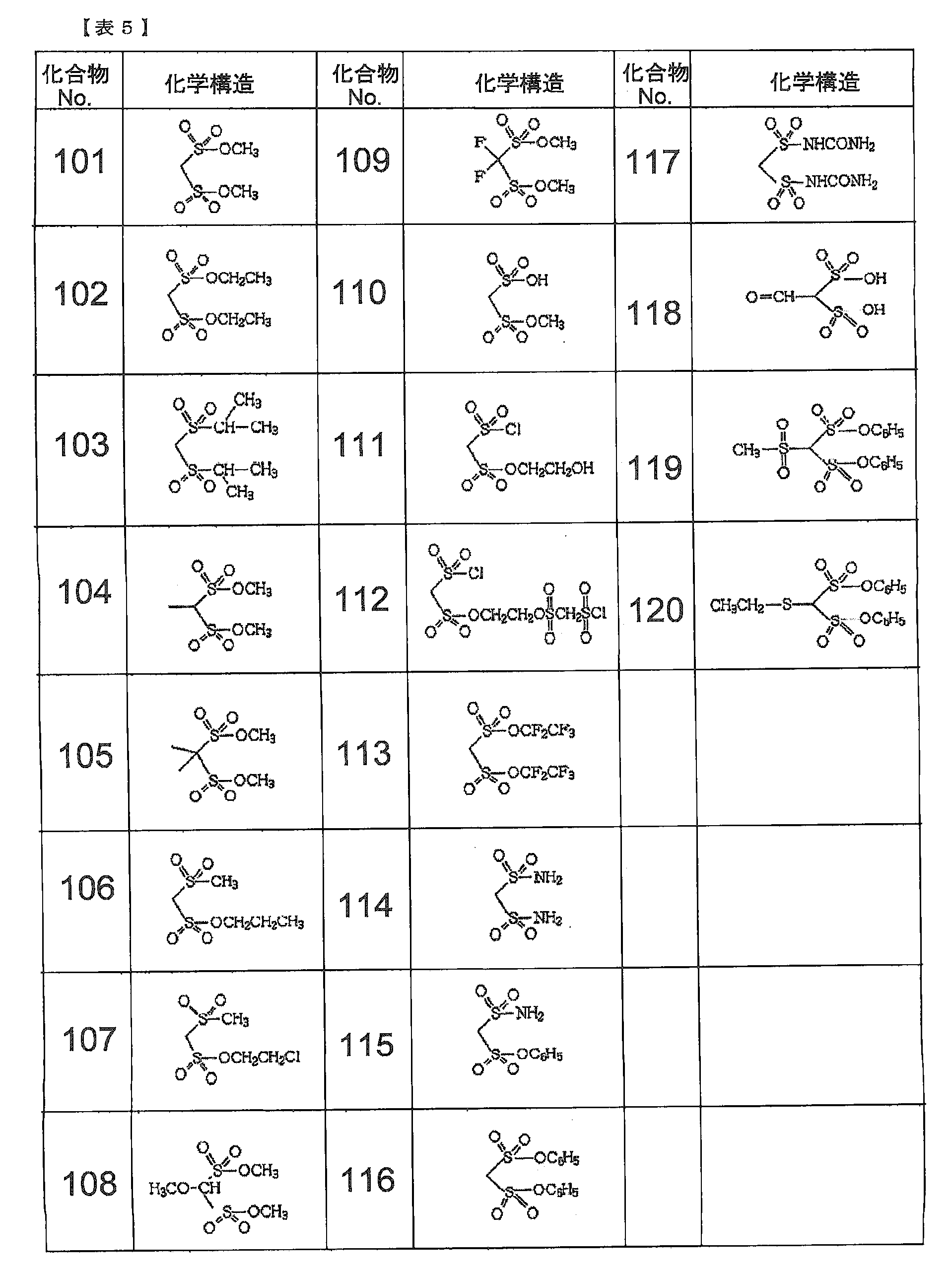
- the electrolyte solution for a secondary battery according to this embodiment includes at least an aprotic solvent, a compound represented by the following formula (1), and a compound represented by the following formula (2).
- Q represents an oxygen atom, a methylene group or a single bond.
- a 1 represents a substituted or unsubstituted alkylene group having 1 to 5 carbon atoms, a carbonyl group, a sulfinyl group, a substituted or unsubstituted carbon number. 1 to 6 fluoroalkylene group, an alkylene unit or a divalent group having 2 to 6 carbon atoms bonded to the fluoroalkylene unit via an ether bond,
- a 2 is a substituted or unsubstituted alkylene group, substituted or unsubstituted A fluoroalkylene group or an oxygen atom.
- T2 represents an alkylene group (CH 2 ) n , and n is an integer of 1 to 4.
- m (R 16 ) each independently represents a halogen atom or a carbon number of 1 to 6; An alkyl group, a haloalkyl group having 1 to 6 carbon atoms, an alkenyl group having 2 to 8 carbon atoms, an alkynyl group having 2 to 8 carbon atoms, or an aryl group, and each m is an integer of 0 to 3)
- the secondary battery according to the present embodiment includes a positive electrode, a negative electrode, and an electrolyte for a secondary battery according to the present embodiment.
- the secondary battery electrolyte according to the present embodiment can provide a secondary battery having excellent charge / discharge efficiency, good cycle characteristics, and a high capacity retention rate.
- FIG. 6 is a diagram showing the results of negative electrode surface energy dispersive X-ray analysis (EDX) after cycling of secondary batteries in Comparative Example 6, Comparative Example 8 and Example 1.
- EDX negative electrode surface energy dispersive X-ray analysis
- An electrolyte solution for a secondary battery according to this embodiment (hereinafter also referred to as an electrolyte solution) includes at least an aprotic solvent, a compound represented by the formula (1), and a compound represented by the formula (2). Including.
- the present inventors have added the compound represented by the above formula (1) and the compound represented by the above formula (2) as an alternative to LiBOB to the electrolyte solution, thereby adding these onto the electrode. It was found that a stable mixed film of the above compound was formed, and elution of the active material into the electrolytic solution and decomposition of the electrolytic solution were suppressed. Furthermore, by the synergistic action of these compounds, the compound represented by the formula (1) effectively suppresses gas generation caused by the compound represented by the formula (2), and is represented by the formula (2). The compound was also found to suppress gas generation caused by the compound represented by the formula (1).
- the surface of the positive electrode and the negative electrode is stable.
- a uniform film is formed, elution of a positive electrode active material such as manganese into the electrolytic solution is suppressed, and decomposition of the electrolytic solution is suppressed, so that a secondary battery excellent in discharge capacity and cycle characteristics can be provided.
- the aprotic solvent is at least selected from the group consisting of cyclic carbonates, chain carbonates, aliphatic carboxylic acid esters, ⁇ -lactones, cyclic ethers, chain ethers and their fluorinated derivatives.
- One organic solvent can be used.
- cyclic carbonates such as propylene carbonate (PC), ethylene carbonate (EC), butylene carbonate (BC), and derivatives thereof; dimethyl carbonate (DMC), diethyl carbonate (DEC), ethyl methyl carbonate ( EMC), dipropyl carbonate (DPC), and chain carbonates such as derivatives thereof; aliphatic carboxylic acid esters such as methyl formate, methyl acetate, ethyl propionate, and derivatives thereof; ⁇ -butyrolactone, and these ⁇ -lactones such as derivatives thereof; cyclic ethers such as tetrahydrofuran, 2-methyltetrahydrofuran, and derivatives thereof; 1,2-diethoxyethane (DEE), ethoxymethoxyethane (EME), diethyl ether, and And chain ethers such as these derivatives; dimethyl sulfoxide, 1,3-dioxolane, formamide, acetamide, dimethylform
- a 1 represents a substituted or unsubstituted alkylene group having 1 to 5 carbon atoms, carbon, from the viewpoints of stability of the compound, ease of synthesis of the compound, solubility in a solvent, cost, and the like.
- At least one CC bond in the polyfluoroalkylene group having 1 to 5 carbon atoms, the substituted or unsubstituted fluoroalkylene group having 1 to 5 carbon atoms, or the substituted or unsubstituted alkylene group having 1 to 5 carbon atoms is C— A group in which an O—C bond is formed, a group in which at least one CC bond in a polyfluoroalkylene group having 1 to 5 carbon atoms is a C—O—C bond, and a substituted or unsubstituted carbon atom having 1 to A group selected from groups in which at least one CC bond in the fluoroalkylene group 5 is a C—O—C bond is preferable.
- a group selected from a substituted or unsubstituted alkylene group having 1 to 5 carbon atoms, a polyfluoroalkylene group having 1 to 5 carbon atoms, and a substituted or unsubstituted fluoroalkylene group having 1 to 5 carbon atoms is more preferable.
- an unsubstituted alkylene group having 1 to 5 carbon atoms is more preferable, and a methylene group, an ethylene group, or a 2,2-propanediyl group is particularly preferable.
- the fluoroalkylene group having 1 to 5 carbon atoms preferably includes a methylene group and a difluoromethylene group, and more preferably includes a methylene group and a difluoromethylene group.
- a 2 is preferably an alkylene group having 1 to 5 carbon atoms, more preferably a methylene group, a 1,1-ethanediyl group, or a 2,2-propanediyl group.
- examples of T2 include a methylene group, an ethylene group, an n-propylene group, and an n-butylene group.
- N in (CH 2 ) n of T2 can be 2-4.
- R 16 is preferably F, Cl, methyl group, ethyl group, n-propyl group, n-butyl group, phenyl group or the like.
- the compound represented by the formula (1) has two sulfonyl groups, has a small LUMO, and is easily reduced.
- Compound No. The LUMO of 1 is as small as -1.8 eV.
- the compound represented by the formula (2) is a compound that easily undergoes an oxidation reaction and a reduction reaction.
- Compound No. The LUMO of 201 methylenebis (benzenesulfonate)
- the HOMO is -9.95 eV.
- the compounds represented by the above formulas (1) and (2) are more aprotic solvents such as cyclic carbonates and chain carbonates (for example, LUMO in ethylene carbonate is 1.2 eV and HOMO is ⁇ 11.8 eV). It is considered that the LUMO is small and the reduced film is formed on the negative electrode before the solvent.
- the compound represented by the formula (2) since the compound represented by the formula (2) has a lower LUMO than the compound represented by the formula (1), when viewed from the LUMO, the compound represented by the formula (2) is higher than the compound represented by the formula (1). It is considered that the compound represented by is easier to form a reduction film on the electrode (positive electrode, negative electrode) and more advantageous.
- the compound represented by the formula (1) is preferably contained in the electrolytic solution in an amount of 0.1% by mass to 5% by mass, and more preferably 0.5% by mass to 2% by mass.
- the compound represented by the formula (1) is contained in the electrolytic solution in these concentration ranges, it is sufficiently effective for forming a film by an electrochemical reaction on the electrode surface, and the viscosity of the electrolytic solution is used. It can be kept in a suitable range.
- the compounds represented by the formula (1) can be used alone or in combination of two or more.
- the compound represented by the formula (2) can be produced with reference to, for example, Japanese Patent Application Laid-Open No. 2011-088914 and Japanese Patent No. 4682248.
- the compound represented by the formula (2) is preferably contained in the electrolytic solution in an amount of 0.05% by mass or more and 1.5% by mass or less, and more preferably 0.1% by mass or more and 1% by mass or less.
- the compound represented by the formula (2) is contained in the electrolyte solution in these concentration ranges, it is sufficiently effective for forming a film by an electrochemical reaction on the electrode surface, and gas is not generated and is safe. Above preferred.
- the compounds represented by the formula (2) can be used alone or in combination of two or more.
- the compound shown by said Formula (1) and (2) is contained 0.005 mass% or more and 10 mass% or less of the whole electrolyte solution, and 0.01 to 5 mass% is contained. Is more preferable.
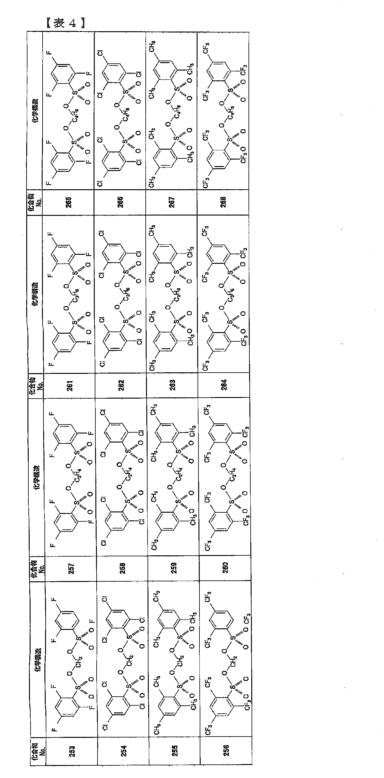
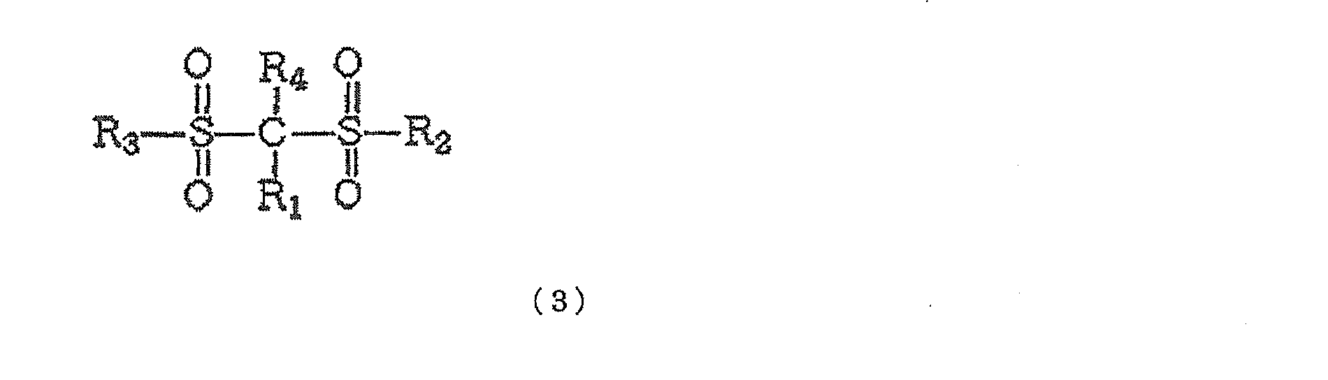
- the electrolytic solution according to the present embodiment preferably includes a disulfonic acid ester represented by the following formula (3).
- R 1 and R 4 are each independently a hydrogen atom, a substituted or unsubstituted alkyl group having 1 to 5 carbon atoms, a substituted or unsubstituted alkoxy group having 1 to 5 carbon atoms, A substituted or unsubstituted fluoroalkyl group having 1 to 5 carbon atoms, a perfluoroalkyl group having 1 to 5 carbon atoms, —SO 2 X 9 (X 9 is a substituted or unsubstituted alkyl group having 1 to 5 carbon atoms), From —SY 1 (Y 1 is a substituted or unsubstituted alkyl group having 1 to 5 carbon atoms), —COZ (Z is a hydrogen atom, or a substituted or unsubstituted alkyl group having 1 to 5 carbon atoms), and a halogen atom R 2 and R 3 each independently represents a substituted or unsubstituted alkyl group having 1 to 5 carbon
- —NY 2 CONY 3 Y 4 (Y 2 to Y 4 are each independently a hydrogen atom or a substituted or unsubstituted alkyl group having 1 to 5 carbon atoms) or one atom or group selected from the group consisting of Is shown.)
- R 1 and R 4 in the formula (3) each independently represents a hydrogen atom, an alkyl group having 1 to 5 carbon atoms, a halogen atom, and —SO 2 X 9 (X 9 is a substituted or unsubstituted alkyl group having 1 to 5 carbon atoms).
- An atom or group selected from is preferable, and a hydrogen atom or an unsubstituted alkyl group having 1 to 5 carbon atoms is more preferable, and a hydrogen atom or a methyl group is more preferable.
- R 1 and R 4 is where R 1 and R 4 is a hydrogen atom. This is because when R 1 and R 4 are hydrogen atoms, the methylene moiety sandwiched between the two sulfonyl groups is activated and a reaction film is easily formed on the electrode.
- R 2 and R 3 are each independently a substituted or unsubstituted C 1-5 carbon atom from the viewpoint of the stability of the compound, the ease of synthesis of the compound, the solubility in a solvent, the price, etc.
- R 2 and R 3 are substituted or unsubstituted alkoxy groups having 1 to 5 carbon atoms. It is.
- the substituted or unsubstituted alkyl group having 1 to 5 carbon atoms is preferably a methyl group or an ethyl group, and the substituted or unsubstituted alkoxy group having 1 to 5 carbon atoms is preferably a methoxy group or An ethoxy group is preferred.
- the content of the compound represented by the formula (3) in the electrolytic solution is not particularly limited, but is 0.1% by mass or more in the electrolytic solution. It is preferably contained in an amount of 0% by mass or less. If it is less than 0.1% by mass, a sufficient effect may not be exhibited in forming a film by an electrochemical reaction on the electrode surface. If it exceeds 5.0 mass%, the viscosity of the electrolytic solution may increase.
- the formula (1), the formula ( 2) and 10 to 90% by mass of the total mass of the compound represented by the formula (3) is preferable.
- the electrolytic solution according to the present embodiment may further include one or more compounds having a sulfonyl group.
- a sultone compound represented by the following formula (4) it is preferable to include a sultone compound represented by the following formula (4).
- R 5 to R 10 are each independently a hydrogen atom, an alkyl group having 1 to 12 carbon atoms, a cycloalkyl group having 3 to 6 carbon atoms, and 6 to 12 carbon atoms.
- the viscosity of the electrolytic solution can be easily adjusted by adding a sultone compound represented by the formula (4).
- the stability of the surface film is improved by using a combination of compounds having a sulfonyl group due to a synergistic effect.
- decomposition suppression of solvent molecules can be suppressed.
- the effect of removing moisture in the electrolytic solution is increased.
- sultone compound examples include sulfolane, 1,3-propane sultone, 1,4-butane sultone, alkanesulfonic acid anhydride, ⁇ -sultone compound, sulfolene derivative, and the like, but are not limited thereto. is not.
- a sultone compound when a sultone compound is further added to the electrolytic solution, it can be added in an amount of 0.005 mass% to 10 mass% in the electrolytic solution. By adding 0.005 mass% or more, a surface film can be effectively formed on the negative electrode surface. More preferably, 0.01% by mass or more can be added. Moreover, the solubility of a sultone compound is maintained by adding 10 mass% or less, and the viscosity increase of electrolyte solution can be suppressed. More preferably, 5 mass% or less can be added.
- the electrolytic solution according to the present embodiment dissolves or disperses the compounds represented by the above formulas (1) and (2) and, if necessary, sultone compounds, lithium salts, and other additives in an aprotic solvent. Is obtained. By mixing additives having different properties, a surface film having different properties can be formed on the negative electrode surface, so that battery characteristics are improved.
- the electrolytic solution further contains vinylene carbonate (VC) or a derivative thereof
- VC vinylene carbonate
- the addition amount of VC or a derivative thereof is preferably 0.01% by mass or more and 10% by mass or less of the entire electrolytic solution. By being 0.01 mass% or more, cycle characteristics can be improved, and resistance increase during storage at high temperatures can be suppressed.
- the resistance value of electrolyte solution can be made low by being 10 mass% or less.
- the electrolytic solution according to the present embodiment can include an electrolyte.
- a lithium salt is used and dissolved in an aprotic solvent.
- the lithium imide salt LiN (C k F 2k + 1 SO 2) 2 and LiN (C n F 2n + 1 SO 2) (C m F 2m + 1 SO 2) (k, n, m are natural numbers) are exemplified. These can be used alone or in combination of two or more. By including these lithium salts, a high energy density can be achieved.
- the secondary battery according to the present embodiment includes at least a positive electrode, a negative electrode, and an electrolyte for a secondary battery according to the present embodiment.
- FIG. 1 shows a schematic structure of an example of the secondary battery according to the present embodiment.
- the secondary battery includes a positive electrode current collector 21, a layer 22 containing a positive electrode active material that can occlude and release lithium ions, a layer 23 containing a negative electrode active material that occludes and releases lithium ions, and a negative electrode current collector 24. , And a separator 25 containing an electrolytic solution.
- the electrolytic solution contains a cyclic disulfonic acid compound (cyclic disulfonic acid ester) represented by the formula (1) and a compound represented by the formula (2).
- the secondary battery which concerns on this embodiment is covered with the laminate exterior body.
- the positive electrode current collector 21 aluminum, stainless steel, nickel, titanium, or an alloy thereof can be used.
- the negative electrode current collector 24 copper, stainless steel, nickel, titanium, or an alloy thereof can be used.
- Separator 25 As the separator 25, it is preferable to use a polyolefin such as polypropylene or polyethylene, or a porous film such as a fluororesin.
- the lithium-containing composite oxide examples include a lithium-manganese composite oxide having a spinel structure, an olivine-type lithium-containing composite oxide, and an inverse spinel-type lithium-containing composite oxide. Since these positive electrode active materials have a high operating voltage, the electrolytic solution is likely to be decomposed. In particular, when a lithium manganese composite oxide having a spinel structure such as LiMn 2 O 4 is used as the positive electrode active material, elution of manganese into the electrolytic solution due to an increase in the hydrogen ion concentration of the electrolytic solution occurs. As a result, the discharge capacity and cycle characteristics are reduced.
- the positive electrode active material is dispersed and kneaded in a solvent such as N-methyl-2-pyrrolidone (NMP) together with a conductive material such as carbon black and a binder such as polyvinylidene fluoride (PVDF).
- NMP N-methyl-2-pyrrolidone
- PVDF polyvinylidene fluoride
- the layer 22 containing the positive electrode active material can be obtained by a method such as coating on a substrate such as a foil.
- Carbon is preferably used as the negative electrode active material.
- carbon lithium-occluded graphite, amorphous carbon, diamond-like carbon, carbon nanotube, and the like can be used. Of these, graphite or amorphous carbon is preferred.
- the graphite material has high electron conductivity, excellent adhesion to a current collector made of a metal such as copper, and voltage flatness, and is formed at a high processing temperature, so it contains few impurities and has negative electrode performance. It is preferable from the viewpoint of being advantageous for improvement.
- An oxide can also be used as the negative electrode active material.
- silicon oxide, tin oxide, indium oxide, zinc oxide, lithium oxide, phosphoric acid, boric acid, or a composite thereof can be used, and silicon oxide is particularly preferable.
- the oxide structure is preferably in an amorphous state. This is because silicon oxide is stable and does not cause a reaction with other compounds, and the amorphous structure does not lead to deterioration due to nonuniformity such as crystal grain boundaries and defects.
- a film forming method a vapor deposition method, a CVD method, a sputtering method, or the like can be used.
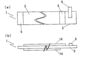
- Example 1 The production of the positive electrode will be described with reference to FIG. 2A shows a top view of the positive electrode, and FIG. 2B shows a side view of the positive electrode.
- 85% by mass of LiMn 2 O 4 , 7% by mass of acetylene black as a conductive auxiliary material, 8% by mass of polyvinylidene fluoride as a binder were mixed, N-methylpyrrolidone was added and further mixed to prepare a positive electrode slurry. This was applied to both surfaces of a 20 ⁇ m thick Al foil 2 serving as a current collector by a doctor blade method so that the thickness after the roll press treatment was 180 ⁇ m.
- the positive electrode active material double-side coating part 3 was formed through the press process.
- One end of the positive electrode 1 is provided with a positive electrode active material non-applied portion 5 where no positive electrode active material is applied on any surface, and a positive electrode active material single-side applied portion 4 where a positive electrode active material is applied on only one surface.
- the positive electrode conductive tab 6 was provided on the positive electrode active material non-applied portion 5. Further, a positive electrode active material non-applied part 5 was provided at the other end of the positive electrode 1.
- FIG. 3A shows a top view of the negative electrode
- FIG. 3B shows a side view of the negative electrode.
- 90% by mass of graphite, 1% by mass of acetylene black as a conductive auxiliary, 9% by mass of polyvinylidene fluoride as a binder, N-methylpyrrolidone was added and further mixed to prepare a negative electrode slurry. This was applied to both surfaces of a 10 ⁇ m thick Cu foil 8 serving as a current collector so that the thickness after the roll press treatment was 120 ⁇ m. Then, this was dried at 120 degreeC for 5 minute (s), and the negative electrode active material double-side coating part 9 was formed through the press process.
- a negative electrode active material single-side application part 10 in which a negative electrode active material is applied only on one side and a negative electrode active material non-application part 11 in which no negative electrode active material is applied are provided at one end of the negative electrode 7.
- a negative electrode conductive tab 12 was attached to the application part 11. Further, a negative electrode active material non-applied part 11 was provided at the other end of the negative electrode 7.
- the production of the battery element will be described with reference to FIG. 2 parts of a separator 13 made of a polypropylene microporous film having a thickness of 25 ⁇ m and a porosity of 55%, which has been subjected to a hydrophilic treatment, is welded and cut on a winding core, and the positive electrode 1 (FIG. 2) And the tip of the negative electrode 7 (FIG. 3) were introduced.
- the positive electrode 1 is on the opposite side of the connecting portion of the positive electrode conductive tab 6, the negative electrode 7 is on the connecting portion side of the negative electrode conductive tab 12, the negative electrode 7 is between the two separators 13, and the positive electrode 1 is the upper surface of the separator 13.
- the battery element hereinafter referred to as jelly roll (J / R) was formed by rotating and winding the core.
- the J / R was housed in an embossed laminate outer package, the positive electrode conductive tab 6 and the negative electrode conductive tab 12 were pulled out, one side of the laminate outer package was folded back, and heat fusion was performed leaving a portion for injection. An electrolyte solution was injected from the injection portion into the laminate outer package, and the injection portion was heat-sealed to produce a secondary battery.
- the obtained secondary battery is charged to a battery voltage of 3.2 V (charging current: 0.2 C, CC charging) as a first charging step, and once opened, vacuum sealed again, and second charged.
- the battery was charged to a battery voltage of 4.2 V (charging current: 0.2 C, CC-CV charging, charging time: 6.5 hours).
- CC discharge was performed at 0.2 C to a battery voltage of 3.0 V, and the discharge capacity at that time was defined as the initial capacity.
- the battery volume change rate after the cycle of the secondary battery was determined as a ratio with the battery volume after 300 cycles, with the battery volume after the initial charge being 1. The results are shown in Table 6.
- the impedance of the secondary battery after initial charge and after 300 cycles was measured using a frequency response analyzer and a potentio / galvanostat to calculate the charge transfer resistance.
- the resistance increase rate is a value obtained by dividing the charge transfer resistance after 300 cycles by the initial charge transfer resistance. The results are shown in Table 6.
- Example 2 In Example 1, compound no. A secondary battery was fabricated in the same manner as in Example 1 except that the amount of 201 was changed to 0.20% by mass. The results are shown in Table 6.
- Example 3 In Example 1, compound no. A secondary battery was fabricated in the same manner as in Example 1 except that the amount of 201 was changed to 1.00% by mass. The results are shown in Table 6.
- Example 4 In Example 1, 1,3-propane sultone was further added so as to contain 1.00% by mass. Otherwise, a secondary battery was fabricated in the same manner as in Example 1. The results are shown in Table 6.
- Example 5 Vinylene carbonate was further added so that it might contain 1.00 mass%. Otherwise, a secondary battery was fabricated in the same manner as in Example 1. The results are shown in Table 6.
- Example 6 In Example 1, 1,3-propane sultone was further added so as to contain 1.00% by mass and vinylene carbonate was added to 1.00% by mass. Otherwise, a secondary battery was fabricated in the same manner as in Example 1. The results are shown in Table 6.
- Example 7 In Example 1, compound no. 1 was adjusted to 0.80%, and the compound No. 1 was further reduced. A secondary battery was fabricated in the same manner as in Example 1 except that 101 was added so that 0.80% was contained. The results are shown in Table 6.
- Example 1 compound no. A secondary battery was fabricated in the same manner as in Example 1 except that 1 was not added. The results are shown in Table 6.
- Example 2 Comparative Example 2 In Example 4, compound no. A secondary battery was fabricated in the same manner as in Example 1 except that 1 was not added. The results are shown in Table 6.
- Example 3 Comparative Example 3
- compound no. A secondary battery was fabricated in the same manner as in Example 1 except that 1 was not added. The results are shown in Table 6.
- Example 6 compound no. A secondary battery was fabricated in the same manner as in Example 1 except that 1 was not added. The results are shown in Table 6.
- Example 7 Comparative Example 5 In Example 7, compound no. A secondary battery was fabricated in the same manner as in Example 1 except that 201 was not added. The results are shown in Table 6.
- Example 1 When the capacity retention rate in the 45 ° C. cycle in Example 1 was compared with Comparative Examples 6 to 9, no significant difference was observed, but in the 60 ° C. cycle, Example 1 showed a significant improvement in cycle characteristics. .
- Comparative Example 6 As shown in FIG. 5, for the batteries shown in Example 1, Comparative Example 6, and Comparative Example 8, the negative electrode surface after 300 cycles at 60 ° C. was examined using energy dispersive X-ray analysis (EDX). As a result, Comparative Example 6 in which no additive was added and Compound No. In Comparative Example 8 in which only 1 was added, a peak indicating Mn was observed, whereas Compound No. 1 and compound no. In Example 1 in which both 201 were added, the intensity of the peak indicating Mn was below the detection limit, and could not be confirmed. From this, it can be said that Comparative Example 8 showed a large Mn elution suppression effect in Example 1 because the amount of Mn elution occurring at the positive electrode was larger than that in Example 1.
- EDX energy dispersive X-ray analysis
- the peak which shows Mn of the comparative example 6 is strong, and it can be said that the additive of the comparative example 8 also showed a certain amount of Mn elution inhibitory effect.
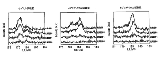
- Example 1 For the secondary batteries shown in Example 1, Comparative Example 1, Comparative Example 6, and Comparative Example 8, the positive electrode surface and the negative electrode surface before and after the cycle were analyzed using X-ray photoelectron spectroscopy (XPS). As a result of peak splitting of the sulfur spectrum, it was confirmed that there were substances having peaks in the vicinity of 164 eV and 169 eV in the positive electrode before the cycle test except for Comparative Example 6 (FIG. 6).
- XPS X-ray photoelectron spectroscopy
- Example 1 Focusing on Comparative Example 1 in which only 201 was added, a peak was observed in the vicinity of 164 eV, but the intensity was weaker than in Example 1 and Comparative Example 8. Further, the difference in peak intensity around 164 eV between the 45 ° C. cycle and the 60 ° C. cycle is the largest in Example 1 (FIG. 8 (1)), and then Comparative Example 8 (FIG. 8 (2)) and Comparative Example 1 ( FIG. 8 (3)) followed by Comparative Example 6 (FIG. 8 (4)). The difference in Comparative Example 6 (FIG. 8 (4)) was not significant because it was not added, and the difference in peak intensity between the 45 ° C. cycle and the 60 ° C. cycle of Comparative Example 1 (FIG.
- Example 1 and Comparative Example 8 there was no difference in capacity retention rate in the 45 ° C. cycle, and the difference in the 60 ° C. cycle was consistent with the tendency of the peak behavior around 164 eV. It is presumed that the cycle characteristics have been improved by increasing the ratio of the above, that is, by forming a better quality film. Further, when Comparative Example 1 and Comparative Example 6 were compared, the cycle characteristics of Comparative Example 1 were better in both 45 ° C. and 60 ° C. cycles, and particularly better in the 60 ° C. cycle. The peak near 164 eV in the 45 ° C. cycle and the 60 ° C. cycle cannot be confirmed in Comparative Example 6, but is confirmed in Comparative Example 1, and the peak intensity is larger at 60 ° C. than at 45 ° C. From this, it can be said that there is a correlation between the difference in cycle characteristics and the peak intensity, as described above.
- Example 1 In Example 1 in which both 201 were added, only slight attenuation was observed. This difference in peak intensity indicates the proportion of the bonded state, and here, it is considered that it represents the state of the film formed on the negative electrode.
- Compound No. 1 shows that the cycle characteristics at 60 ° C. are better in Example 1 than in Comparative Example 8. 1 and compound no. It is presumed that by adding both 201, the proportion of the bonded state was significantly increased compared to the case where each was added alone, that is, a higher quality film was formed.
- Example 7 Comparative Examples 10 to 16
- a secondary battery was produced in the same manner as in Example 1, and cycle evaluation at 60 ° C. was performed. The results are shown in Table 7.
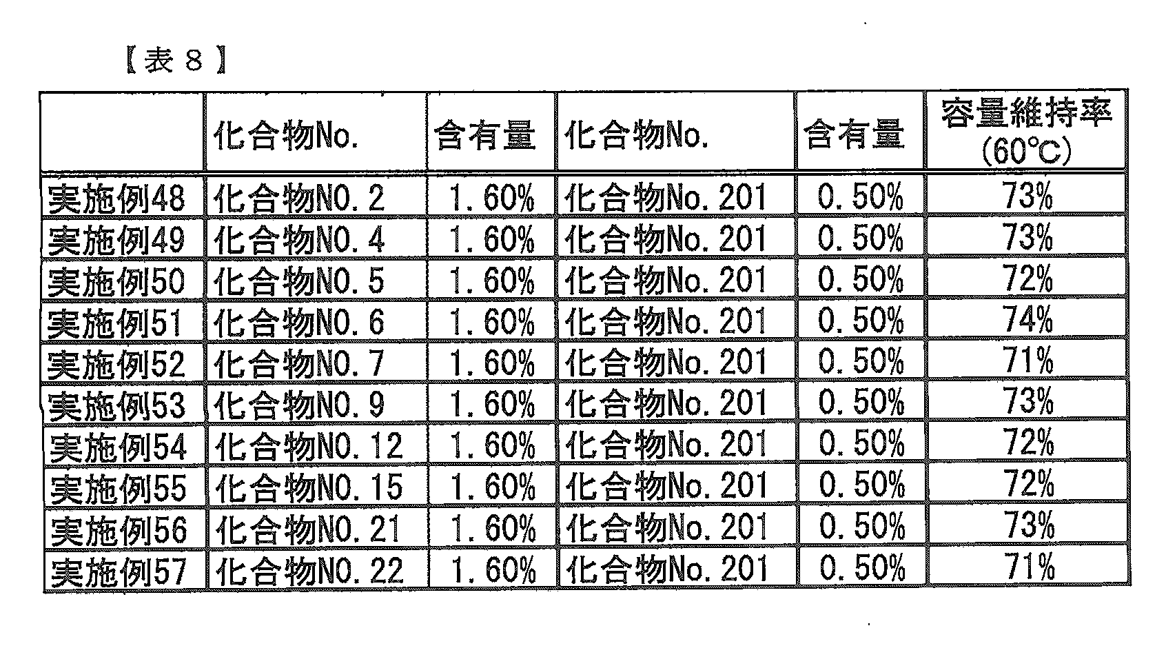
- Example 48 Using the compounds shown in Table 8 as additives contained in the electrolytic solution, a secondary battery was produced in the same manner as in Example 1, and cycle evaluation at 60 ° C. was performed. The results are shown in Table 8.
- This embodiment can also be used for other energy storage devices such as electric double layer capacitors and lithium ion capacitors.
Abstract
Description


本実施形態に係る二次電池は、正極と、負極と、本実施形態に係る二次電池用電解液とを備える。
The secondary battery according to the present embodiment includes a positive electrode, a negative electrode, and an electrolyte for a secondary battery according to the present embodiment.
本実施形態に係る二次電池用電解液(以下、電解液とも示す)は、少なくとも非プロトン性溶媒と、前記式(1)で示される化合物と、前記式(2)で示される化合物とを含む。 [Electrolyte]
An electrolyte solution for a secondary battery according to this embodiment (hereinafter also referred to as an electrolyte solution) includes at least an aprotic solvent, a compound represented by the formula (1), and a compound represented by the formula (2). Including.
非プロトン性溶媒としては、環状カーボネート類、鎖状カーボネート類、脂肪族カルボン酸エステル類、γ-ラクトン類、環状エーテル類、鎖状エーテル類およびこれらのフッ化誘導体からなる群から選択される少なくとも1種の有機溶媒を用いることができる。より具体的には、プロピレンカーボネート(PC)、エチレンカーボネート(EC)、ブチレンカーボネート(BC)、およびこれらの誘導体等の環状カーボネート類;ジメチルカーボネート(DMC)、ジエチルカーボネート(DEC)、エチルメチルカーボネート(EMC)、ジプロピルカーボネート(DPC)、およびこれらの誘導体等の鎖状カーボネート類;ギ酸メチル、酢酸メチル、プロピオン酸エチル、およびこれらの誘導体等の脂肪族カルボン酸エステル類;γ-ブチロラクトン、およびこれらの誘導体等のγ-ラクトン類;テトラヒドロフラン、2-メチルテトラヒドロフラン、およびこれらの誘導体等の環状エーテル類;1,2-ジエトキシエタン(DEE)、エトキシメトキシエタン(EME)、ジエチルエーテル、およびこれらの誘導体等の鎖状エーテル類;ジメチルスルホキシド、1,3-ジオキソラン、ホルムアミド、アセトアミド、ジメチルホルムアミド、アセトニトリル、プロピオニトリル、ニトロメタン、エチルモノグライム、リン酸トリエステル、トリメトキシメタン、ジオキソラン誘導体、メチルスルホラン、1,3-ジメチル-2-イミダゾリジノン、3-メチル-2-オキサゾリジノン、アニソール、N-メチルピロリドン、フッ素化カルボン酸エステル等が挙げられる。これらは一種又は二種以上を混合して使用することができる。 (Aprotic solvent)
The aprotic solvent is at least selected from the group consisting of cyclic carbonates, chain carbonates, aliphatic carboxylic acid esters, γ-lactones, cyclic ethers, chain ethers and their fluorinated derivatives. One organic solvent can be used. More specifically, cyclic carbonates such as propylene carbonate (PC), ethylene carbonate (EC), butylene carbonate (BC), and derivatives thereof; dimethyl carbonate (DMC), diethyl carbonate (DEC), ethyl methyl carbonate ( EMC), dipropyl carbonate (DPC), and chain carbonates such as derivatives thereof; aliphatic carboxylic acid esters such as methyl formate, methyl acetate, ethyl propionate, and derivatives thereof; γ-butyrolactone, and these Γ-lactones such as derivatives thereof; cyclic ethers such as tetrahydrofuran, 2-methyltetrahydrofuran, and derivatives thereof; 1,2-diethoxyethane (DEE), ethoxymethoxyethane (EME), diethyl ether, and And chain ethers such as these derivatives; dimethyl sulfoxide, 1,3-dioxolane, formamide, acetamide, dimethylformamide, acetonitrile, propionitrile, nitromethane, ethyl monoglyme, phosphoric acid triester, trimethoxymethane, dioxolane derivative, methyl Examples include sulfolane, 1,3-dimethyl-2-imidazolidinone, 3-methyl-2-oxazolidinone, anisole, N-methylpyrrolidone, and fluorinated carboxylic acid ester. These can be used alone or in combination of two or more.
本実施形態によれば、非プロトン性溶媒に、少なくとも前記式(1)で示される化合物と、前記式(2)で表される化合物とが含まれる電解液を適用することによって、前記式(1)と(2)で示される化合物の相乗効果により、これらの化合物をそれぞれ単独で電解液に添加した場合よりも優れた充放電効率、抵抗上昇抑制効果、ガス発生抑制効果、サイクル特性を有する二次電池用電解液を得ることができる。 (Additive)
According to this embodiment, by applying an electrolytic solution containing at least a compound represented by the formula (1) and a compound represented by the formula (2) to an aprotic solvent, the formula ( Due to the synergistic effect of the compounds represented by 1) and (2), these compounds have better charge / discharge efficiency, resistance increase suppression effect, gas generation suppression effect, and cycle characteristics than when these compounds are added to the electrolyte alone. An electrolytic solution for a secondary battery can be obtained.


本実施形態に係る電解液は電解質を含むことができる。電解質は、リチウム二次電池の場合にはリチウム塩を用い、これを非プロトン性溶媒中に溶解させる。リチウム塩としては、リチウムイミド塩、LiPF6、LiAsF6、LiAlCl4、LiClO4、LiBF4、LiSbF6などが挙げられる。この中でも特にLiPF6、LiBF4が好ましい。リチウムイミド塩としてはLiN(CkF2k+1SO2)2及びLiN(CnF2n+1SO2)(CmF2m+1SO2)(k、n、mは自然数)が挙げられる。これらは単独で、又は複数種を組み合わせて用いることができる。これらのリチウム塩を含むことで高エネルギー密度を達成することができる。 (Electrolytes)
The electrolytic solution according to the present embodiment can include an electrolyte. As the electrolyte, in the case of a lithium secondary battery, a lithium salt is used and dissolved in an aprotic solvent. The lithium salt,
本実施形態に係る二次電池は、少なくとも正極と負極と本実施形態に係る二次電池用電解液とを備える。図1に本実施形態に係る二次電池の一例について概略構造を示す。該二次電池は、正極集電体21、リチウムイオンを吸蔵、放出し得る正極活物質を含有する層22、リチウムイオンを吸蔵、放出する負極活物質を含有する層23、負極集電体24、および電解液を含むセパレータ25から構成されている。ここで、該電解液は、前記式(1)で示される環状のジスルホン酸化合物(環状のジスルホン酸エステル)及び前記式(2)で示される化合物を含む。また、本実施形態に係る二次電池はラミネート外装体により覆われていることが好ましい。 [Secondary battery]
The secondary battery according to the present embodiment includes at least a positive electrode, a negative electrode, and an electrolyte for a secondary battery according to the present embodiment. FIG. 1 shows a schematic structure of an example of the secondary battery according to the present embodiment. The secondary battery includes a positive electrode
正極集電体21としてはアルミニウム、ステンレス鋼、ニッケル、チタンまたはこれらの合金などを用いることができる。負極集電体24としては銅、ステンレス鋼、ニッケル、チタンまたはこれらの合金を用いることができる。 (Current collector)
As the positive electrode
セパレータ25としては、ポリプロピレン、ポリエチレン等のポリオレフィン、フッ素樹脂等の多孔性フィルムを用いることが好ましい。 (Separator)
As the
正極活物質としては、リチウムを吸蔵、放出できるリチウム含有複合酸化物を用いることが好ましい。具体的には、LiMO2(MはMn、Fe、Co、およびNiから選択される少なくとも1種を含み、さらにMの一部はMg、Al、Tiなどその他カチオンで置換されていてもよい)、Li1+xMn2-x-yMyO4-z(0≦x≦0.2、0≦y<2、x+y≦2、-0.1≦z≦0.1、M=Ni、Mg、Al、Ti、Co、Fe、CrおよびCuから選ばれる少なくとも1種以上である)などが好ましい。リチウム含有複合酸化物としては、スピネル構造を有するリチウムマンガン複合酸化物、オリビン型リチウム含有複合酸化物、逆スピネル型リチウム含有複合酸化物等が挙げられる。これらの正極活物質は高い作動電圧を有するため電解液の分解が起こりやすい。特に、LiMn2O4などのスピネル構造を有するリチウムマンガン複合酸化物を正極活物質として用いた場合、さらに電解液の水素イオン濃度の上昇などに起因する電解液中へのマンガンの溶出が起き、結果として放電容量やサイクル特性が低下する。 (Positive electrode)
As the positive electrode active material, it is preferable to use a lithium-containing composite oxide capable of inserting and extracting lithium. Specifically, LiMO 2 (M includes at least one selected from Mn, Fe, Co, and Ni, and a part of M may be substituted with other cations such as Mg, Al, Ti) Li 1 + x Mn 2-xy M y O 4-z (0 ≦ x ≦ 0.2, 0 ≦ y <2, x + y ≦ 2, −0.1 ≦ z ≦ 0.1, M = Ni, Mg And at least one selected from Al, Ti, Co, Fe, Cr and Cu). Examples of the lithium-containing composite oxide include a lithium-manganese composite oxide having a spinel structure, an olivine-type lithium-containing composite oxide, and an inverse spinel-type lithium-containing composite oxide. Since these positive electrode active materials have a high operating voltage, the electrolytic solution is likely to be decomposed. In particular, when a lithium manganese composite oxide having a spinel structure such as LiMn 2 O 4 is used as the positive electrode active material, elution of manganese into the electrolytic solution due to an increase in the hydrogen ion concentration of the electrolytic solution occurs. As a result, the discharge capacity and cycle characteristics are reduced.
負極活物質としては、炭素を用いることが好ましい。炭素としては、リチウムを吸蔵する黒鉛、非晶質炭素、ダイヤモンド状炭素、カーボンナノチューブなどを用いることができる。このうち、黒鉛または非晶質炭素が好ましい。特に、黒鉛材料は、電子伝導性が高く、銅などの金属からなる集電体との接着性と電圧平坦性が優れており、高い処理温度によって形成されるため含有不純物が少なく、負極性能の向上に有利である観点から好ましい。また、負極活物質として酸化物を用いることもできる。酸化物としては、酸化シリコン、酸化スズ、酸化インジウム、酸化亜鉛、酸化リチウム、リン酸、ホウ酸のいずれか、あるいはこれらの複合物を用いることができ、特に酸化シリコンを用いることが好ましい。酸化物の構造としてはアモルファス状態であることが好ましい。これは、酸化シリコンが安定で他の化合物との反応を引き起こさないため、またアモルファス構造が結晶粒界、欠陥といった不均一性に起因する劣化を導かないためである。成膜方法としては、蒸着法、CVD法、スパッタリング法などの方法を用いることができる。 (Negative electrode)
Carbon is preferably used as the negative electrode active material. As carbon, lithium-occluded graphite, amorphous carbon, diamond-like carbon, carbon nanotube, and the like can be used. Of these, graphite or amorphous carbon is preferred. In particular, the graphite material has high electron conductivity, excellent adhesion to a current collector made of a metal such as copper, and voltage flatness, and is formed at a high processing temperature, so it contains few impurities and has negative electrode performance. It is preferable from the viewpoint of being advantageous for improvement. An oxide can also be used as the negative electrode active material. As the oxide, silicon oxide, tin oxide, indium oxide, zinc oxide, lithium oxide, phosphoric acid, boric acid, or a composite thereof can be used, and silicon oxide is particularly preferable. The oxide structure is preferably in an amorphous state. This is because silicon oxide is stable and does not cause a reaction with other compounds, and the amorphous structure does not lead to deterioration due to nonuniformity such as crystal grain boundaries and defects. As a film forming method, a vapor deposition method, a CVD method, a sputtering method, or the like can be used.
図2により正極の作製について説明する。図2(a)は正極の上面図、図2(b)は正極の側面図を示している。LiMn2O4を85質量%、導電補助材としてアセチレンブラックを7質量%、バインダーとしてポリフッ化ビニリデンを8質量%混合し、N-メチルピロリドンを加えてさらに混合し、正極スラリーを作製した。これをドクターブレード法により集電体となる厚さ20μmのAl箔2の両面にロールプレス処理後の厚さが180μmになるように塗布した。その後、これを120℃で5分間乾燥し、プレス工程を経て正極活物質両面塗布部3を形成した。なお、正極1の一方の端部にはいずれの面にも正極活物質が塗布されていない正極活物質非塗布部5と、片面のみ正極活物質を塗布した正極活物質片面塗布部4を設け、正極活物質非塗布部5に正極導電タブ6を設けた。また、正極1のもう一方の端部には正極活物質非塗布部5を設けた。 (Example 1)
The production of the positive electrode will be described with reference to FIG. 2A shows a top view of the positive electrode, and FIG. 2B shows a side view of the positive electrode. 85% by mass of LiMn 2 O 4 , 7% by mass of acetylene black as a conductive auxiliary material, 8% by mass of polyvinylidene fluoride as a binder were mixed, N-methylpyrrolidone was added and further mixed to prepare a positive electrode slurry. This was applied to both surfaces of a 20 μm
実施例1において、化合物No.201の量を0.20質量%にした他は、実施例1と同様にして二次電池を作製した。結果を表6に示す。 (Example 2)
In Example 1, compound no. A secondary battery was fabricated in the same manner as in Example 1 except that the amount of 201 was changed to 0.20% by mass. The results are shown in Table 6.
実施例1において、化合物No.201の量を1.00質量%にした他は、実施例1と同様にして二次電池を作製した。結果を表6に示す。 (Example 3)
In Example 1, compound no. A secondary battery was fabricated in the same manner as in Example 1 except that the amount of 201 was changed to 1.00% by mass. The results are shown in Table 6.
実施例1において、さらに1,3-プロパンスルトンを1.00質量%含まれるように加えた。他は、実施例1と同様にして二次電池を作製した。結果を表6に示す。 (Example 4)
In Example 1, 1,3-propane sultone was further added so as to contain 1.00% by mass. Otherwise, a secondary battery was fabricated in the same manner as in Example 1. The results are shown in Table 6.
実施例1において、さらにビニレンカーボネートを1.00質量%含まれるように加えた。他は、実施例1と同様にして二次電池を作製した。結果を表6に示す。 (Example 5)
In Example 1, vinylene carbonate was further added so that it might contain 1.00 mass%. Otherwise, a secondary battery was fabricated in the same manner as in Example 1. The results are shown in Table 6.
実施例1において、さらに1,3-プロパンスルトンを1.00質量%、ビニレンカーボネートを1.00質量%含まれるように加えた。他は、実施例1と同様にして二次電池を作製した。結果を表6に示す。 (Example 6)
In Example 1, 1,3-propane sultone was further added so as to contain 1.00% by mass and vinylene carbonate was added to 1.00% by mass. Otherwise, a secondary battery was fabricated in the same manner as in Example 1. The results are shown in Table 6.
実施例1において、化合物No.1の量を0.80%にし、さらに化合物No.101を0.80%含まれるように加えた他は、実施例1と同様にして二次電池を作製した。結果を表6に示す。 (Example 7)
In Example 1, compound no. 1 was adjusted to 0.80%, and the compound No. 1 was further reduced. A secondary battery was fabricated in the same manner as in Example 1 except that 101 was added so that 0.80% was contained. The results are shown in Table 6.
実施例1において、化合物No.1を加えない他は、実施例1と同様にして二次電池を作製した。結果を表6に示す。 (Comparative Example 1)
In Example 1, compound no. A secondary battery was fabricated in the same manner as in Example 1 except that 1 was not added. The results are shown in Table 6.
実施例4において、化合物No.1を加えない他は、実施例1と同様にして二次電池を作製した。結果を表6に示す。 (Comparative Example 2)
In Example 4, compound no. A secondary battery was fabricated in the same manner as in Example 1 except that 1 was not added. The results are shown in Table 6.
実施例5において、化合物No.1を加えない他は、実施例1と同様にして二次電池を作製した。結果を表6に示す。 (Comparative Example 3)
In Example 5, compound no. A secondary battery was fabricated in the same manner as in Example 1 except that 1 was not added. The results are shown in Table 6.
実施例6において、化合物No.1を加えない他は、実施例1と同様にして二次電池を作製した。結果を表6に示す。 (Comparative Example 4)
In Example 6, compound no. A secondary battery was fabricated in the same manner as in Example 1 except that 1 was not added. The results are shown in Table 6.
実施例7において、化合物No.201を加えない他は、実施例1と同様にして二次電池を作製した。結果を表6に示す。 (Comparative Example 5)
In Example 7, compound no. A secondary battery was fabricated in the same manner as in Example 1 except that 201 was not added. The results are shown in Table 6.
添加剤を何も加えない他は、実施例1と同様にして二次電池を作製した。結果を表6に示す。 (Comparative Example 6)
A secondary battery was fabricated in the same manner as in Example 1 except that no additive was added. The results are shown in Table 6.
化合物No.1のみ0.80質量%含まれるように加えた他は、実施例1と同様にして二次電池を作製した。結果を表6に示す。 (Comparative Example 7)
Compound No. A secondary battery was fabricated in the same manner as in Example 1 except that only 1 was added so that 0.81% by mass was contained. The results are shown in Table 6.
化合物No.1のみ1.60質量%含まれるように加えた他は、実施例1と同様にして二次電池を作製した。結果を表6に示す。 (Comparative Example 8)
Compound No. A secondary battery was fabricated in the same manner as in Example 1 except that only 1 was added so as to be contained at 1.60% by mass. The results are shown in Table 6.
化合物No.1のみ2.10質量%含まれるように加えた他は、実施例1と同様にして二次電池を作製した。結果を表6に示す。 (Comparative Example 9)
Compound No. A secondary battery was fabricated in the same manner as in Example 1 except that only 1 was added so as to be contained at 2.10% by mass. The results are shown in Table 6.

電解液に含まれる添加物として表7に示す化合物を用いて、実施例1と同様にして二次電池を作製し、60℃におけるサイクル評価を行った。結果を表7に示す。 (Examples 8 to 47, Comparative Examples 10 to 16)
Using the compounds shown in Table 7 as additives contained in the electrolytic solution, a secondary battery was produced in the same manner as in Example 1, and cycle evaluation at 60 ° C. was performed. The results are shown in Table 7.

電解液に含まれる添加物として表8に示す化合物を用いて、実施例1と同様にして二次電池を作製し、60℃におけるサイクル評価を行った。結果を表8に示す。
Using the compounds shown in Table 8 as additives contained in the electrolytic solution, a secondary battery was produced in the same manner as in Example 1, and cycle evaluation at 60 ° C. was performed. The results are shown in Table 8.
電解液に含まれる添加物として化合物No.1と表9に示す化合物を用いて、実施例1と同様にして二次電池を作製し、60℃におけるサイクル評価を行った。結果を表10に示す。
As an additive contained in the electrolytic solution, Compound No. Using the compounds shown in Table 1 and Table 9, a secondary battery was fabricated in the same manner as in Example 1, and the cycle evaluation at 60 ° C. was performed. The results are shown in Table 10.
2 Al箔
3 正極活物質両面塗布部
4 正極活物質片面塗布部
5 正極活物質非塗布部
6 正極導電タブ
7 負極
8 Cu箔
9 負極活物質両面塗布部
10 負極活物質片面塗布部
11 負極活物質非塗布部
12 負極導電タブ
13 セパレータ
14 正極活物質を含有する層
15 負極活物質を含有する層
21 正極集電体
22 正極活物質を含有する層
23 負極活物質を含有する層
24 負極集電体
25 セパレータ DESCRIPTION OF
Claims (15)
- 少なくとも非プロトン性溶媒と、下記式(1)で示される化合物と、下記式(2)で示される化合物とを含む二次電池用電解液。

- さらに下記式(3)で示される鎖状ジスルホン酸エステルを含む請求項1に記載の二次電池用電解液。

- さらに下記式(4)で示されるスルトン化合物を含む請求項1または2に記載の二次電池用電解液。

- 前記式(1)および(2)に示される化合物が、電解液全体の0.005質量%以上10質量%以下含まれる請求項1から3のいずれか1項に記載の二次電池用電解液。 The electrolytic solution for a secondary battery according to any one of claims 1 to 3, wherein the compound represented by the formulas (1) and (2) is contained in an amount of 0.005 mass% to 10 mass% of the entire electrolytic solution. .
- 前記式(2)に示される化合物が、電解液全体の0.05質量%以上1.5質量%以下含まれる請求項1から3のいずれか1項に記載の二次電池用電解液。 The electrolytic solution for a secondary battery according to any one of claims 1 to 3, wherein the compound represented by the formula (2) is contained in an amount of 0.05% by mass or more and 1.5% by mass or less of the entire electrolytic solution.
- 前記式(2)に示される化合物が、電解液全体の0.1質量%以上1質量%以下含まれる請求項1から3のいずれか1項に記載の二次電池用電解液。 The electrolyte solution for secondary batteries according to any one of claims 1 to 3, wherein the compound represented by the formula (2) is contained in an amount of 0.1% by mass or more and 1% by mass or less of the entire electrolyte solution.
- さらにビニレンカーボネート又はその誘導体を含む請求項1から6のいずれか1項に記載の二次電池用電解液。 The electrolyte solution for a secondary battery according to any one of claims 1 to 6, further comprising vinylene carbonate or a derivative thereof.
- 電解質としてリチウム塩を含む請求項1から7のいずれか1項に記載の二次電池用電解液。 The electrolyte solution for a secondary battery according to any one of claims 1 to 7, comprising a lithium salt as an electrolyte.
- 前記リチウム塩が、LiPF6、LiBF4、LiAsF6、LiSbF6、LiClO4、LiAlCl4およびLiN(CkF2k+1SO2)(CmF2m+1SO2)(k、mはそれぞれ独立して1又は2である)からなる群から選択される少なくとも1種である請求項8に記載の二次電池用電解液。 The lithium salt is LiPF 6 , LiBF 4 , LiAsF 6 , LiSbF 6 , LiClO 4 , LiAlCl 4 and LiN (C k F 2k + 1 SO 2 ) (C m F 2m + 1 SO 2 ) (k and m are each independently 1 The electrolyte solution for secondary batteries according to claim 8, which is at least one selected from the group consisting of:
- 前記非プロトン性溶媒が、環状カーボネート類、鎖状カーボネート類、脂肪族カルボン酸エステル類、γ-ラクトン類、環状エーテル類、鎖状エーテル類およびこれらのフッ化誘導体からなる群から選択される少なくとも1種である請求項1から9のいずれか1項に記載の二次電池用電解液。 The aprotic solvent is at least selected from the group consisting of cyclic carbonates, chain carbonates, aliphatic carboxylic acid esters, γ-lactones, cyclic ethers, chain ethers, and fluorinated derivatives thereof. It is 1 type, The electrolyte solution for secondary batteries of any one of Claim 1 to 9.
- 正極と、負極と、請求項1から10のいずれか1項に記載の二次電池用電解液とを備える二次電池。 A secondary battery comprising a positive electrode, a negative electrode, and the electrolyte solution for a secondary battery according to any one of claims 1 to 10.
- 前記正極が、正極活物質としてリチウムを吸蔵、放出できるリチウム含有複合酸化物を含む請求項11に記載の二次電池。 The secondary battery according to claim 11, wherein the positive electrode includes a lithium-containing composite oxide capable of inserting and extracting lithium as a positive electrode active material.
- 前記リチウム含有複合酸化物が、スピネル構造を有するリチウムマンガン複合酸化物である請求項12に記載の二次電池。 The secondary battery according to claim 12, wherein the lithium-containing composite oxide is a lithium manganese composite oxide having a spinel structure.
- 前記負極が、負極活物質として炭素を含む請求項11から13のいずれか1項に記載の二次電池。 The secondary battery according to any one of claims 11 to 13, wherein the negative electrode contains carbon as a negative electrode active material.
- ラミネート外装体により覆われている請求項11から14のいずれか1項に記載の二次電池。 The secondary battery according to any one of claims 11 to 14, which is covered with a laminate outer package.
Priority Applications (4)
| Application Number | Priority Date | Filing Date | Title |
|---|---|---|---|
| JP2014504977A JP6099155B2 (en) | 2012-03-13 | 2013-03-13 | Secondary battery electrolyte and secondary battery using the same |
| CN201380012225.2A CN104145365A (en) | 2012-03-13 | 2013-03-13 | Secondary battery electrolyte and secondary battery using same |
| EP13760900.4A EP2827433B1 (en) | 2012-03-13 | 2013-03-13 | Secondary battery electrolyte and secondary battery using same |
| US14/377,577 US20160049691A1 (en) | 2012-03-13 | 2013-03-13 | Electrolytic solution for secondary battery and secondary battery using the same |
Applications Claiming Priority (2)
| Application Number | Priority Date | Filing Date | Title |
|---|---|---|---|
| JP2012-055907 | 2012-03-13 | ||
| JP2012055907 | 2012-03-13 |
Publications (1)
| Publication Number | Publication Date |
|---|---|
| WO2013137351A1 true WO2013137351A1 (en) | 2013-09-19 |
Family
ID=49161256
Family Applications (1)
| Application Number | Title | Priority Date | Filing Date |
|---|---|---|---|
| PCT/JP2013/057083 WO2013137351A1 (en) | 2012-03-13 | 2013-03-13 | Secondary battery electrolyte and secondary battery using same |
Country Status (5)
| Country | Link |
|---|---|
| US (1) | US20160049691A1 (en) |
| EP (1) | EP2827433B1 (en) |
| JP (1) | JP6099155B2 (en) |
| CN (1) | CN104145365A (en) |
| WO (1) | WO2013137351A1 (en) |
Cited By (11)
| Publication number | Priority date | Publication date | Assignee | Title |
|---|---|---|---|---|
| CN103825048A (en) * | 2014-02-27 | 2014-05-28 | 宁德新能源科技有限公司 | Lithium ion secondary cell and its electrolyte |
| JP2015090857A (en) * | 2013-11-07 | 2015-05-11 | 三星エスディアイ株式会社Samsung SDI Co.,Ltd. | Lithium ion secondary battery |
| WO2015194559A1 (en) * | 2014-06-16 | 2015-12-23 | 日本電気株式会社 | Electrolyte and secondary cell |
| WO2016025589A1 (en) * | 2014-08-14 | 2016-02-18 | E. I. Du Pont De Nemours And Company | Nonaqueous electrolyte compositions comprising sultone and fluorinated solvent |
| US9673450B2 (en) | 2011-09-02 | 2017-06-06 | Solvay Sa | Lithium ion battery |
| US9882244B2 (en) | 2013-11-07 | 2018-01-30 | Samsung Sdi Co., Ltd. | Rechargeable lithium ion battery |
| US9979050B2 (en) | 2011-09-02 | 2018-05-22 | Solvay Sa | Fluorinated electrolyte compositions |
| US10044066B2 (en) | 2012-06-01 | 2018-08-07 | Solvary SA | Fluorinated electrolyte compositions |
| US10074874B2 (en) | 2012-06-01 | 2018-09-11 | Solvay Sa | Additives to improve electrolyte performance in lithium ion batteries |
| US10516187B2 (en) | 2015-03-25 | 2019-12-24 | Sumitomo Chemical Company, Limited | Nonaqueous electrolyte for sodium secondary battery and sodium secondary battery |
| US10686220B2 (en) | 2013-04-04 | 2020-06-16 | Solvay Sa | Nonaqueous electrolyte compositions |
Families Citing this family (5)
| Publication number | Priority date | Publication date | Assignee | Title |
|---|---|---|---|---|
| CA2887996A1 (en) * | 2012-10-30 | 2014-05-08 | Nec Corporation | Lithium secondary battery |
| CN106505249B (en) * | 2016-12-15 | 2021-01-05 | 东莞市杉杉电池材料有限公司 | Lithium ion battery electrolyte and lithium ion battery containing same |
| KR102459627B1 (en) * | 2017-08-16 | 2022-10-28 | 삼성전자주식회사 | Disulfonate-based additive and Lithium secondary battery comprising the same |
| JP6500154B1 (en) * | 2017-09-29 | 2019-04-10 | 日本山村硝子株式会社 | Release agent coating apparatus for glass bottle finishing mold, release agent coating method for glass bottle finishing mold, glass bottle manufacturing apparatus, and glass bottle manufacturing method |
| JP6577127B1 (en) * | 2018-12-27 | 2019-09-18 | 日本山村硝子株式会社 | Device for applying release agent to glass bottle molds |
Citations (12)
| Publication number | Priority date | Publication date | Assignee | Title |
|---|---|---|---|---|
| JPS63102173A (en) | 1986-10-16 | 1988-05-07 | Hitachi Maxell Ltd | Lithium secondary battery |
| JPH04169075A (en) | 1990-10-31 | 1992-06-17 | Sanyo Electric Co Ltd | Nonaqueous electrolyte battery |
| JP2004281368A (en) | 2002-08-29 | 2004-10-07 | Nec Corp | Electrolyte solution for secondary battery and secondary battery using the same |
| JP2005203342A (en) | 2003-12-15 | 2005-07-28 | Nec Corp | Secondary battery |
| JP2006244776A (en) | 2005-03-01 | 2006-09-14 | Nec Corp | Electrolyte for secondary battery, and the secondary battery using the same |
| JP2011088914A (en) | 2006-09-12 | 2011-05-06 | Wako Pure Chem Ind Ltd | Method of producing disulfonic acid ester |
| JP2011165553A (en) * | 2010-02-12 | 2011-08-25 | Nec Energy Devices Ltd | Polymer electrolyte and secondary battery using the same |
| JP2011238373A (en) | 2010-05-06 | 2011-11-24 | Sony Corp | Secondary battery, electrolytic solution for secondary battery, electric tool, electric vehicle, and power storage system |
| WO2011152534A1 (en) * | 2010-06-04 | 2011-12-08 | 宇部興産株式会社 | Nonaqueous electrolyte solution and electrochemical element using same |
| WO2012017999A1 (en) | 2010-08-05 | 2012-02-09 | 和光純薬工業株式会社 | Nonaqueous electrolyte solution and nonaqueous electrolyte battery using same |
| WO2012017998A1 (en) | 2010-08-05 | 2012-02-09 | 和光純薬工業株式会社 | Nonaqueous electrolyte solution, method for producing same, and nonaqueous electrolyte battery using the electrolyte solution |
| JP2012033346A (en) * | 2010-07-29 | 2012-02-16 | Nec Energy Devices Ltd | Aprotic electrolyte secondary battery |
Family Cites Families (3)
| Publication number | Priority date | Publication date | Assignee | Title |
|---|---|---|---|---|
| JP2010062113A (en) * | 2008-09-08 | 2010-03-18 | Nec Tokin Corp | Lithium ion secondary battery |
| ES2633805T3 (en) * | 2009-08-07 | 2017-09-25 | Wako Pure Chemical Industries, Ltd. | New disulfonic acid ester as an additive for an electrolyte for a secondary lithium battery |
| WO2011099580A1 (en) * | 2010-02-10 | 2011-08-18 | Necエナジーデバイス株式会社 | Nonaqueous electrolyte solution, and lithium ion secondary battery using same |
-
2013
- 2013-03-13 JP JP2014504977A patent/JP6099155B2/en active Active
- 2013-03-13 WO PCT/JP2013/057083 patent/WO2013137351A1/en active Application Filing
- 2013-03-13 EP EP13760900.4A patent/EP2827433B1/en active Active
- 2013-03-13 CN CN201380012225.2A patent/CN104145365A/en active Pending
- 2013-03-13 US US14/377,577 patent/US20160049691A1/en not_active Abandoned
Patent Citations (13)
| Publication number | Priority date | Publication date | Assignee | Title |
|---|---|---|---|---|
| JPS63102173A (en) | 1986-10-16 | 1988-05-07 | Hitachi Maxell Ltd | Lithium secondary battery |
| JPH04169075A (en) | 1990-10-31 | 1992-06-17 | Sanyo Electric Co Ltd | Nonaqueous electrolyte battery |
| JP2004281368A (en) | 2002-08-29 | 2004-10-07 | Nec Corp | Electrolyte solution for secondary battery and secondary battery using the same |
| JP2005203342A (en) | 2003-12-15 | 2005-07-28 | Nec Corp | Secondary battery |
| JP2006244776A (en) | 2005-03-01 | 2006-09-14 | Nec Corp | Electrolyte for secondary battery, and the secondary battery using the same |
| JP4682248B2 (en) | 2006-09-12 | 2011-05-11 | 和光純薬工業株式会社 | Method for producing sulfonate ester |
| JP2011088914A (en) | 2006-09-12 | 2011-05-06 | Wako Pure Chem Ind Ltd | Method of producing disulfonic acid ester |
| JP2011165553A (en) * | 2010-02-12 | 2011-08-25 | Nec Energy Devices Ltd | Polymer electrolyte and secondary battery using the same |
| JP2011238373A (en) | 2010-05-06 | 2011-11-24 | Sony Corp | Secondary battery, electrolytic solution for secondary battery, electric tool, electric vehicle, and power storage system |
| WO2011152534A1 (en) * | 2010-06-04 | 2011-12-08 | 宇部興産株式会社 | Nonaqueous electrolyte solution and electrochemical element using same |
| JP2012033346A (en) * | 2010-07-29 | 2012-02-16 | Nec Energy Devices Ltd | Aprotic electrolyte secondary battery |
| WO2012017999A1 (en) | 2010-08-05 | 2012-02-09 | 和光純薬工業株式会社 | Nonaqueous electrolyte solution and nonaqueous electrolyte battery using same |
| WO2012017998A1 (en) | 2010-08-05 | 2012-02-09 | 和光純薬工業株式会社 | Nonaqueous electrolyte solution, method for producing same, and nonaqueous electrolyte battery using the electrolyte solution |
Non-Patent Citations (1)
| Title |
|---|
| See also references of EP2827433A4 |
Cited By (15)
| Publication number | Priority date | Publication date | Assignee | Title |
|---|---|---|---|---|
| US9979050B2 (en) | 2011-09-02 | 2018-05-22 | Solvay Sa | Fluorinated electrolyte compositions |
| US9673450B2 (en) | 2011-09-02 | 2017-06-06 | Solvay Sa | Lithium ion battery |
| US10074874B2 (en) | 2012-06-01 | 2018-09-11 | Solvay Sa | Additives to improve electrolyte performance in lithium ion batteries |
| US10044066B2 (en) | 2012-06-01 | 2018-08-07 | Solvary SA | Fluorinated electrolyte compositions |
| US10916805B2 (en) | 2013-04-04 | 2021-02-09 | Solvay Sa | Nonaqueous electrolyte compositions |
| US10686220B2 (en) | 2013-04-04 | 2020-06-16 | Solvay Sa | Nonaqueous electrolyte compositions |
| US9882244B2 (en) | 2013-11-07 | 2018-01-30 | Samsung Sdi Co., Ltd. | Rechargeable lithium ion battery |
| JP2015090857A (en) * | 2013-11-07 | 2015-05-11 | 三星エスディアイ株式会社Samsung SDI Co.,Ltd. | Lithium ion secondary battery |
| CN103825048A (en) * | 2014-02-27 | 2014-05-28 | 宁德新能源科技有限公司 | Lithium ion secondary cell and its electrolyte |
| US10566661B2 (en) | 2014-06-16 | 2020-02-18 | Nec Corporation | Electrolytic solution and secondary battery |
| WO2015194559A1 (en) * | 2014-06-16 | 2015-12-23 | 日本電気株式会社 | Electrolyte and secondary cell |
| JP2017531285A (en) * | 2014-08-14 | 2017-10-19 | ソルヴェイ(ソシエテ アノニム) | Non-aqueous electrolyte composition comprising sultone and a fluorinated solvent |
| WO2016025589A1 (en) * | 2014-08-14 | 2016-02-18 | E. I. Du Pont De Nemours And Company | Nonaqueous electrolyte compositions comprising sultone and fluorinated solvent |
| US10673096B2 (en) | 2014-08-14 | 2020-06-02 | Solvay Sa | Nonaqueous electrolyte compositions comprising sultone and fluorinated solvent |
| US10516187B2 (en) | 2015-03-25 | 2019-12-24 | Sumitomo Chemical Company, Limited | Nonaqueous electrolyte for sodium secondary battery and sodium secondary battery |
Also Published As
| Publication number | Publication date |
|---|---|
| JPWO2013137351A1 (en) | 2015-08-03 |
| EP2827433A4 (en) | 2015-10-21 |
| CN104145365A (en) | 2014-11-12 |
| EP2827433B1 (en) | 2019-09-25 |
| US20160049691A1 (en) | 2016-02-18 |
| JP6099155B2 (en) | 2017-03-22 |
| EP2827433A1 (en) | 2015-01-21 |
Similar Documents
| Publication | Publication Date | Title |
|---|---|---|
| JP6099155B2 (en) | Secondary battery electrolyte and secondary battery using the same | |
| JP6398985B2 (en) | Lithium ion secondary battery | |
| US8455142B2 (en) | Non-aqueous electrolyte and non-aqueous electrolyte secondary battery using the same | |
| JP5236875B2 (en) | Nonaqueous electrolyte and nonaqueous electrolyte secondary battery using the same | |
| JP4948025B2 (en) | Non-aqueous secondary battery | |
| WO2017022615A1 (en) | Nonaqueous electrolyte solution for lithium secondary batteries, positive electrode for lithium secondary batteries, method for producing positive electrode for lithium secondary batteries, and lithium secondary battery | |
| JP5310711B2 (en) | Nonaqueous electrolyte secondary battery | |
| JP6380377B2 (en) | Lithium ion secondary battery | |
| JP2006244776A (en) | Electrolyte for secondary battery, and the secondary battery using the same | |
| JP5472554B1 (en) | Non-aqueous electrolyte secondary battery | |
| JP2005149750A (en) | Nonaqueous electrolyte secondary battery | |
| US20190181494A1 (en) | Nonaqueous electrolytic solution and lithium ion secondary battery | |
| JP2010129192A (en) | Lithium ion secondary battery and method for manufacturing the same | |
| JP4968614B2 (en) | Secondary battery electrolyte and secondary battery using the same | |
| US8563179B2 (en) | Nonaqueous secondary battery | |
| JP6036697B2 (en) | Non-aqueous secondary battery | |
| JP2005228631A (en) | Electrolytic solution for secondary battery, and secondary battery using the same | |
| WO2016021596A1 (en) | Lithium secondary battery and production method for same | |
| JP5421220B2 (en) | Secondary battery electrolyte and secondary battery | |
| JP6341195B2 (en) | Secondary battery electrolyte and secondary battery using the same | |
| WO2020054866A1 (en) | Nonaqueous secondary battery | |
| WO2013183769A1 (en) | Lithium-ion secondary battery | |
| WO2014171518A2 (en) | Lithium-ion secondary battery | |
| JPWO2016098428A1 (en) | Lithium ion secondary battery | |
| JP6258180B2 (en) | ELECTROLYTE SOLUTION FOR LITHIUM SECONDARY BATTERY, ELECTROLYTE SOLUTION FOR LITHIUM SECONDARY BATTERY USING THE SAME, LITHIUM SECONDARY BATTERY |
Legal Events
| Date | Code | Title | Description |
|---|---|---|---|
| 121 | Ep: the epo has been informed by wipo that ep was designated in this application |
Ref document number: 13760900 Country of ref document: EP Kind code of ref document: A1 |
|
| WWE | Wipo information: entry into national phase |
Ref document number: 2013760900 Country of ref document: EP |
|
| WWE | Wipo information: entry into national phase |
Ref document number: 14377577 Country of ref document: US |
|
| ENP | Entry into the national phase |
Ref document number: 2014504977 Country of ref document: JP Kind code of ref document: A |
|
| NENP | Non-entry into the national phase |
Ref country code: DE |