WO2013137336A1 - 風速計 - Google Patents
風速計 Download PDFInfo
- Publication number
- WO2013137336A1 WO2013137336A1 PCT/JP2013/057049 JP2013057049W WO2013137336A1 WO 2013137336 A1 WO2013137336 A1 WO 2013137336A1 JP 2013057049 W JP2013057049 W JP 2013057049W WO 2013137336 A1 WO2013137336 A1 WO 2013137336A1
- Authority
- WO
- WIPO (PCT)
- Prior art keywords
- anemometer
- circuit
- thermocouple
- output
- chip
- Prior art date
- Legal status (The legal status is an assumption and is not a legal conclusion. Google has not performed a legal analysis and makes no representation as to the accuracy of the status listed.)
- Ceased
Links
Images



Classifications
-
- G—PHYSICS
- G01—MEASURING; TESTING
- G01P—MEASURING LINEAR OR ANGULAR SPEED, ACCELERATION, DECELERATION, OR SHOCK; INDICATING PRESENCE, ABSENCE, OR DIRECTION, OF MOVEMENT
- G01P5/00—Measuring speed of fluids, e.g. of air stream; Measuring speed of bodies relative to fluids, e.g. of ship, of aircraft
- G01P5/10—Measuring speed of fluids, e.g. of air stream; Measuring speed of bodies relative to fluids, e.g. of ship, of aircraft by measuring thermal variables
-
- G—PHYSICS
- G01—MEASURING; TESTING
- G01P—MEASURING LINEAR OR ANGULAR SPEED, ACCELERATION, DECELERATION, OR SHOCK; INDICATING PRESENCE, ABSENCE, OR DIRECTION, OF MOVEMENT
- G01P13/00—Indicating or recording presence, absence, or direction, of movement
- G01P13/02—Indicating direction only, e.g. by weather vane
Definitions
- the present invention relates to an anemometer, and more particularly to an anemometer using a thermocouple.
- thermocouple As a method for measuring the wind direction and the wind speed, for example, a method using a thermocouple as in Patent Document 1 is known.
- the temperature difference according to a wind speed is produced on a printed circuit board by heating surrounding air using a heating wire. Since the thermocouple formed on the printed circuit board generates an electromotive force according to the temperature difference between the terminals, the wind direction is measured by detecting the electromotive force. The air volume is measured using a thermistor.
- Patent Document 1 it is necessary to secure a large area on the printed circuit board in order to form a heating wire (or heater), a thermocouple, and a thermistor.
- thermocouple and a heater inside the IC chip Therefore, a method of reducing the area necessary for measuring the wind direction and the wind speed by forming a thermocouple and a heater inside the IC chip has been proposed.
- FIG. 4A is a cross-sectional view showing a configuration of a conventional anemometer 101.
- the anemometer 101 is configured by adhering an IC chip 103 to the back surface of a ceramic disk 102 and sealing the IC chip 103 with a resin 104.
- the temperature distribution on the surface of the ceramic disk 102 changes.
- the wind direction anemometer 101 measures the wind direction and the wind speed.
- the IC chip 103 includes a thermocouple 105, a heater 106, and a measurement circuit unit 110.
- the thermocouple 105 and the heater 106 are formed on each side of the IC chip 103.
- a temperature difference corresponding to the wind speed is generated on the back surface of the ceramic disk 102.
- the wind direction anemometer 101 can measure the wind speed by measuring the difference in the electromotive force by the measurement circuit unit 110.
- the wind direction anemometer 101 can also measure a wind direction by measuring the difference of each electromotive force of the thermocouple 105 which faces the vertical direction by the measurement circuit unit 110.
- the measurement circuit unit 110 of the IC chip 103 includes a comparator 111 and a latch circuit 112.
- the comparator 111 detects the difference in electromotive force of the thermocouple 105, and the latch circuit 112 holds the result.
- the comparator 111 is realized by a preamplifier using an offset removal function.
- the output of the latch circuit 112 is connected to the heater 106 inside the IC chip 103, and the measurement circuit unit 110 controls the heater 106 so that the temperature difference between the terminals of the thermocouple 105 becomes zero. Since the output of the latch circuit 112 is 0 or 1 serial data, it is leveled by the filter circuit 120 provided outside the IC chip 103 and read as wind speed.
- the conventional anemometer 101 is configured to detect a weak electromotive force difference from the thermocouple 105 with the comparator 111, the measurement sensitivity is low. Therefore, it is necessary to provide the IC chip 103 on a plate having high thermal conductivity such as the ceramic disk 102. Since the ceramic disk 102 is expensive, and it is necessary to pour the resin 104 after bonding the IC chip 103 to the ceramic disk 102, the anemometer 101 is difficult to mass-produce. For this reason, the anemometer 101 has a problem that it costs more than when the IC chip 103 is mounted on a printed circuit board.
- the anemometer 101 requires a filter circuit 120 that equalizes the output of the latch circuit 112.
- the filter circuit 120 is large in size and easily generates heat, it is usually necessary to provide the filter circuit 120 outside the IC chip 103. For this reason, there is a problem in that the implementation of the filter circuit 120 is expensive.
- the present invention has been made to solve the above problems, and an object thereof is to provide an anemometer using a thermocouple at a low cost.
- an anemometer is an anemometer including a thermocouple that generates an electromotive force due to a temperature difference between two terminals, and a heater that generates heat, An integration circuit that integrates a signal according to an electromotive force from a thermocouple, and the output of the integration circuit is compared with a reference value, and when the output of the integration circuit exceeds the reference value, the integration circuit is set to a predetermined value.
- a comparison circuit that outputs a reset signal for returning to a state and a measurement circuit that measures a wind speed based on an interval at which the reset signal is output are provided.
- thermocouple due to the heat generated by the heater, a temperature difference corresponding to the wind speed occurs between the two terminals of the thermocouple, and the thermocouple generates an electromotive force. Further, the integration circuit integrates a signal corresponding to the electromotive force from the thermocouple, and when the output of the integration circuit exceeds the reference value, the comparison circuit outputs a reset signal. The greater the electromotive force from the thermocouple, the shorter the interval at which the reset signal is output, so the measurement circuit can measure the wind speed based on the interval at which the reset signal is output. Therefore, even if the electromotive force from the thermocouple is small, the wind speed can be measured accurately. Therefore, it is not necessary to mount a thermocouple or heater on a ceramic disk having high thermal conductivity. Therefore, an anemometer using a thermocouple can be provided at low cost.
- the anemometer according to the present invention is an anemometer including a thermocouple that generates an electromotive force due to a temperature difference between two terminals, and a heater that generates heat, from the thermocouple.
- a thermocouple that generates an electromotive force due to a temperature difference between two terminals
- a heater that generates heat, from the thermocouple.
- an integration circuit that integrates a signal according to an electromotive force
- an amplification circuit that amplifies the output of the integration circuit, and an output of the amplification circuit is compared with a reference value, and an output of the amplification circuit exceeds the reference value
- a comparison circuit that outputs a reset signal that returns the integration circuit to a predetermined state, and a measurement circuit that measures the wind speed based on the interval at which the reset signal is output, are used.
- the anemometer can be provided at low cost.
- (A) is sectional drawing which shows the structure of the anemometer which concerns on embodiment of this invention
- (b) is a top view which shows the structure of the IC chip of this anemometer. It is a circuit diagram which shows the further detailed structure of the anemometer shown in (b) of FIG. It is a figure which shows operation
- (A) is sectional drawing which shows the structure of the conventional anemometer
- (b) is a top view which shows the structure of IC chip of this anemometer. It is a circuit diagram which shows the further detailed structure of the anemometer shown in FIG.4 (b).
- FIGS. 1 to 3 An embodiment of the present invention will be described with reference to FIGS. 1 to 3 as follows.
- FIG. 1 (Configuration of wind direction anemometer) (A) of FIG. 1 is sectional drawing which shows the structure of the anemometer 1 which concerns on this embodiment.
- the anemometer 1 includes a substrate 2 and an IC chip 3.
- the IC chip 3 is directly mounted on the surface of the substrate 2 and sealed with a resin package 4.
- the wind direction anemometer 1 measures the wind direction and the wind speed on the surface of the package 4 by measuring the temperature distribution on the surface of the package 4.
- the IC chip 3 includes a thermocouple 5, a heater 6, and a measurement circuit unit 10.
- the thermocouple 5 and the heater 6 are formed on each side of the IC chip 3.
- a temperature difference corresponding to the wind speed is generated in the IC chip 3.
- the anemometer 1 measures the wind speed by measuring the electromotive force by the measurement circuit unit 10.
- the wind direction anemometer 1 can also measure the wind direction by measuring the electromotive force between the terminals of the thermocouple 5 facing in the vertical direction by the measurement circuit unit 10.
- the IC chip 3 may include a thermometer.
- a thermometer By incorporating a thermometer in the IC chip 3, it becomes possible to measure the ambient temperature.
- the ambient temperature measured with the thermometer is used to Sensitivity can be corrected.
- the measurement circuit unit 10 of the IC chip 3 includes an integration circuit 11, an amplification circuit 12, a comparison circuit 13, a delay circuit 14, a counter circuit 15, and an oscillation circuit 16.
- the integrating circuit 11 is a differential integrating circuit including an operational amplifier 11a, two capacitors 11b and 11c, and three switches 11d to 11f, and integrates a current flowing by an electromotive force between terminals of the thermocouple 5.
- the operational amplifier 11 a is a fully differential operational amplifier, and two input terminals of the operational amplifier 11 a constitute a differential input of the integrating circuit 11.
- the capacitor 11b and the switch 11d are connected in parallel between the inverting input terminal and the non-inverting output terminal of the operational amplifier 11a.
- the capacitor 11c and the switch 11e are connected between the non-inverting input terminal and the inverting output terminal of the operational amplifier 11a. They are connected in parallel.
- the switch 11f is provided between the two input terminals of the operational amplifier 11a.
- the capacitors 11b and 11c are variable capacitors, and the integration time of the integration circuit 11 can be adjusted by changing the capacitance values of the capacitors 11b and 11c. Further, ON / OFF of the switches 11d to 11f is controlled by a reset signal R described later, and the integration circuit 11 can be returned to a predetermined state by turning on the switches 11d to 11f.
- the amplifier circuit 12 includes an operational amplifier 12a and four resistors 12b to 12e.
- the resistor 12b is connected between the inverting input terminal and the output terminal of the operational amplifier 12a
- the resistor 12c is connected between the non-inverting input terminal of the operational amplifier 12a and the ground.
- the resistor 12d is connected between the non-inverting output terminal of the operational amplifier 11a and the inverting input terminal of the operational amplifier 12a
- the resistor 12e is connected between the inverting output terminal of the operational amplifier 11a and the non-inverting input terminal of the operational amplifier 12a.
- the resistors 12b and 12c are variable resistors, and the amplification factor of the amplifier circuit 12 can be adjusted by changing the resistance values of the resistors 12b and 12c.
- the integrating circuit 11 integrates the current flowing by the electromotive force generated in the thermocouple 5 according to the temperature difference between the terminals, and the amplifying circuit 12 amplifies the output of the integrating circuit 11.
- the signal amplified by the amplifier circuit 12 is compared with the amplified output reference value by the comparator circuit 13, and the comparator circuit 13 outputs a reset signal R when the output of the amplifier circuit 12 exceeds the amplified output reference value.
- the comparison circuit 13 also outputs a determination signal D indicating which temperature of the thermocouple 5 terminal is higher. Thereby, it can be determined which direction the wind direction is between the terminals of the thermocouple 5.
- the reset signal R is input to the integrating circuit 11 and the counter circuit 15 via the delay circuit 14.
- the integration circuit 11 is returned to a predetermined state by the reset signal R.
- the counter circuit 15 receives the clock signal CL from the oscillation circuit 16.
- the counter circuit 15 and the oscillation circuit 16 constitute a measurement circuit that measures the wind speed based on the interval at which the reset signal is output.
- the counter circuit 15 continues to count the number of rising edges of the clock signal CL in the interval at which the reset signal R is output.
- the count number of the counter circuit 15 is taken into a register circuit (not shown) and then returned to a predetermined value, and the counter circuit 15 newly starts counting.
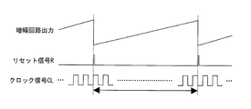
- FIG. 3 is a diagram illustrating an operation of the measurement circuit unit 10 for measuring the wind speed. Assuming that the wind speed is constant, the outputs of the integrating circuit 11 and the amplifying circuit 12 monotonously increase or decrease according to the wind direction. When the output of the amplifier circuit 12 exceeds the amplified output reference value, the reset signal R is output from the comparison circuit 13.
- the counter circuit 15 counts the number of rising edges of the clock signal CL during a period from when the reset signal R rises to when the next reset signal R rises, and stores the count number in the period in the register circuit.
- the number of clocks stored in the register circuit corresponds to the interval at which the reset signal R is output.
- the number of clocks can be read as wind speed by referring to a combination table.
- the measurement circuit unit 10 can measure the wind speed based on the interval at which the reset signal R is output.
- the wind speed can be measured with the IC chip 3 alone, and an external filter circuit is not required as in the prior art.
- the measurement circuit unit 10 is realized by using the integration circuit 11, the wind speed can be accurately measured even when the electromotive force of the thermocouple 5 is small. Therefore, it is not necessary to mount the IC chip 3 on a ceramic disk having a high thermal conductivity. Moreover, even if the temperature difference between the terminals of the thermocouple 5 is reduced by sealing the IC chip 3 with the package 4, no problem occurs. That is, since the IC chip 3 for measuring the wind direction and wind speed can be sealed in the normal package 4, mass production is easy, and the manufacturing cost of the wind direction anemometer 1 can be reduced.
- the thermocouple 5 may be configured to generate an electromotive force according to the temperature distribution on the surface of the IC chip 3 without sealing the IC chip 3 with the package 4. Or you may comprise so that the thermocouple 5 may generate
- the integration circuit 11 and the amplification circuit 12 can adjust the integration time and the amplification factor, respectively. Therefore, instantaneous wind speed measurement and average wind speed measurement can be realized using the same integration circuit 11 and amplification circuit 12.
- the length (output interval) of the reset signal R needs to be changed according to the integration time of the integration circuit 11, and therefore, in the present embodiment, the length of the reset signal R can be adjusted by the delay circuit 14. Yes.
- the frequency of the clock signal CL from the oscillation circuit 16 is variable.
- the frequency of the clock signal CL is adjusted by frequency adjusting means such as a frequency dividing circuit. As the temperature difference between the terminals of the thermocouple 5 becomes smaller, the output interval of the reset signal R becomes longer. Therefore, the counter circuit 15 can be prevented from being saturated by slowing the frequency of the clock signal CL.
- the measurement accuracy of the anemometer 1 can be changed by changing the frequency of the clock signal CL according to the application.
- the electromotive force of the thermocouple 5 can be converted into a current by connecting both ends of the thermocouple 5 to the differential input terminal of the integrating circuit 11.
- the Seebeck coefficient of the thermocouple 5 does not depend on the ambient temperature and the temperature between the terminals of the thermocouple 5 from the relational equation of Mott. It depends only on the difference.
- the integrating circuit 11 uses the capacitors 11b and 11c to integrate the current flowing due to the electromotive force generated in the thermocouple 5, the variation in the absolute values of the capacitors 11b and 11c is the current value, that is, the wind speed. Equivalent to variation. Therefore, it is preferable that the integrating circuit 11 has a redundant capacity in order to correct variations in absolute values of the capacitors 11b and 11c. The accuracy of the relative value of the capacity is more accurate than the accuracy of the absolute value of the capacity.
- a replica circuit that is an integration circuit having the same configuration as the integration circuit 11. By measuring the variation in the absolute values of the capacitors 11b and 11c with this replica circuit, the correction value of the capacitor is calculated.
- the IC chip 3 is mounted on the substrate 2, but the present invention is not limited to this.
- the IC chip 3 may be mounted on a film or plastic surface.
- thermocouple 5 and the heater 6 are mounted inside the IC chip 3, but may be provided outside the IC chip 3.
- the thermocouple 5 and the heater 6 may be directly mounted on the substrate, and the wind speed may be measured based on the temperature distribution on the back surface of the substrate.
- thermocouple 5 is provided along the inner edge of the IC chip 3, but the thermocouple 5 may be provided on the diagonal line of the IC chip 3 or along the diagonal line.
- the output of the integrating circuit 11 is amplified by the amplifier circuit 12, and the amplified output is compared with the amplified output reference value in the comparator circuit 13.
- the present invention is not limited to this. A configuration in which the output of the integrating circuit 11 is compared with a reference value without providing the amplifier circuit 12 may be employed.
- the anemometer 1 is configured to include a plurality of thermocouples 5 in which the directions between terminals are different from each other, but may be configured to include only one thermocouple 5. In that case, the wind direction anemometer 1 may measure only the wind speed without measuring the wind direction.
- the anemometer according to the present invention further includes an amplification circuit that amplifies the output of the integration circuit, and the comparison circuit uses the output of the integration circuit amplified by the amplification circuit as an amplified output reference value.
- the reset signal is output when the amplified output of the integrating circuit exceeds the amplified output reference value.
- the output of the integration circuit is amplified by the amplification circuit, the interval at which the reset signal is output is shortened. For this reason, when a counter circuit is used as a measurement circuit, the counter circuit is less likely to be saturated and measurement is facilitated.
- the amplification factor of the amplifier circuit is preferably variable.
- the integration time of the integration circuit is variable.
- the measurement circuit includes an oscillation circuit that generates a clock signal and a counter circuit that counts the clock signal at intervals at which the reset signal is output.
- the wind speed can be measured.
- the anemometer according to the present invention further includes a register circuit, and the counter circuit is returned to a predetermined state when the reset signal is output, and outputs the count number to the register circuit.
- the counter circuit is returned to a predetermined state by the reset signal, so that a counter circuit with a small number of bits can be used.
- the anemometer according to the present invention preferably includes frequency adjusting means for adjusting the frequency of the clock signal.
- the measurement accuracy of the anemometer can be changed by changing the frequency of the clock signal.
- the frequency adjusting means adjusts the frequency of the clock signal according to a temperature difference between terminals of the thermocouple.
- the counter circuit can be prevented from being saturated by slowing the frequency of the clock signal by the frequency adjusting means.
- the integration circuit is a differential integration circuit, and the two terminals of the thermocouple are respectively connected to a differential input terminal of the integration circuit.
- the electromotive force from the thermocouple can be converted into a current by connecting each terminal of the thermocouple to the differential input terminal of the integrating circuit. This eliminates the need to correct the sensitivity of the thermocouple because the sensitivity of the thermocouple does not depend on the ambient temperature.
- the anemometer according to the present invention preferably includes a delay circuit for adjusting the length of the reset signal.
- the length of the reset signal can be adjusted according to the integration time of the integration circuit.
- the comparison circuit outputs a signal indicating which of the two terminals has a higher temperature.
- the anemometer can determine which direction the wind direction is between the thermocouple terminals.
- thermocouples it is preferable that a plurality of the thermocouples are provided, and the directions between the terminals of the thermocouples are different from each other.
- the wind direction can be accurately measured based on the temperature difference between the terminals of each thermocouple.
- the anemometer according to the present invention preferably includes a replica circuit that is an integration circuit having the same configuration as the integration circuit.
- the variation in the absolute value of the integration capacitance of the integration circuit can be corrected by measuring the variation in the absolute value of the integration capacitance by the replica circuit.
- the anemometer according to the present invention preferably further includes a thermometer for measuring the ambient temperature.
- thermocouple In the anemometer according to the present invention, it is preferable that the sensitivity change of the thermocouple is corrected using the ambient temperature measured by the thermometer.
- the sensitivity of the thermocouple when the sensitivity of the thermocouple changes depending on the ambient temperature, the sensitivity of the thermocouple can be corrected using the ambient temperature measured by the thermometer.
- each of the circuits is preferably built in an IC chip.
- thermocouple and the heater are mounted inside the IC chip.
- the anemometer can be easily downsized.
- thermocouple is preferably provided along the inner edge of the IC chip.
- thermocouple is preferably provided on or along the diagonal line of the IC chip.
- thermocouples having different directions between the terminals are provided, the wind direction can be accurately measured based on the temperature difference between the terminals of each thermocouple.
- thermocouple generates an electromotive force due to a temperature distribution on the surface of the IC chip.
- the wind speed can be measured from the temperature distribution on the surface of the IC chip.
- the IC chip is sealed by a package, and the thermocouple generates an electromotive force due to a temperature distribution on a surface of the package.
- the wind speed can be measured from the temperature distribution on the surface of the package.
- the IC chip is mounted on a substrate, and the thermocouple generates an electromotive force due to a temperature distribution on a back surface of the substrate on which the IC chip is mounted. preferable.
- the wind speed can be measured from the temperature distribution on the back surface of the substrate.
- the present invention can be expressed as follows.
- An anemometer is an anemometer that uses a thermocouple, and integrates a heater that generates heat to create a temperature difference according to the wind speed, and a signal from an electromotive force from the thermocouple.
- thermocouple and the heater are preferably mounted inside the IC.
- thermocouple is preferably placed on the inner edge of the IC.
- thermocouples In the wind direction anemometer according to the present invention, it is preferable to measure the wind direction by detecting a difference in electromotive force between the thermocouples facing each other.
- thermocouple is preferably placed on a diagonal line of the IC.
- both ends of the thermocouple are connected to the differential input of the integrating circuit to convert the electromotive force into a current so that the sensitivity of the thermocouple does not depend on the ambient temperature of the IC. It is preferable to make it.
- the IC is directly mounted on the substrate, and the wind direction and the wind velocity are measured from the temperature distribution of the IC front surface or the back surface of the substrate due to the wind.
- the IC is preferably sealed in a package, and the wind direction and the wind speed are measured from the temperature distribution on the package surface due to the wind.
- the capacitance value of the integration circuit and the resistance value of the amplification circuit are variable in order to make the integration time of the integration circuit and the amplification factor of the amplification circuit variable.
- the comparison circuit also outputs a signal for detecting the wind direction.
- the anemometer according to the present invention has a function of adjusting a clock frequency input so that the counter circuit is not saturated when a temperature difference between the thermocouple terminals changes according to the wind speed. Is preferred.
- the reset signal may be a signal for returning the integration circuit and the counter circuit to a predetermined state and a signal for taking the count number of the counter circuit into a register. preferable.
- the anemometer according to the present invention preferably includes a delay circuit for adjusting the length of the reset signal.
- the anemometer according to the present invention preferably includes a replica circuit having an integration circuit having the same configuration as that of the integration circuit in order to correct variation in the absolute value of the integration capacity of the integration circuit.
- thermometer In the anemometer according to the present invention, it is preferable to measure the ambient temperature by incorporating a thermometer.
- thermocouple it is preferable to correct the change in sensitivity of the thermocouple using the ambient temperature measured by the thermometer.
- the present invention can be used for an anemometer using a thermocouple.
- Anemometer (Anemometer) 2 substrate 3 IC chip 4 package 5 thermocouple 6 heater 10 measuring circuit unit 11 integrating circuit 11a operational amplifier 11b capacitor 11c capacitor 11d switch 11e switch 11f switch 12 amplifier circuit 12a operational amplifier 12b resistor 12c resistor 12d resistor 12e resistor 13 comparison circuit 14 delay circuit 15 Counter circuit 16 Oscillator circuit CL clock signal D determination signal R reset signal
Landscapes
- Physics & Mathematics (AREA)
- General Physics & Mathematics (AREA)
- Engineering & Computer Science (AREA)
- Aviation & Aerospace Engineering (AREA)
- Indicating Or Recording The Presence, Absence, Or Direction Of Movement (AREA)
Abstract
本発明に係る風向風速計(1)は、熱電対(5)と、ヒータと、熱電対(5)からの起電力に応じた信号を積分する積分回路(11)と、積分回路(11)の出力を増幅する増幅回路(12)と、増幅回路(12)の出力が増幅出力基準値を超えた場合に、積分回路(11)を既定の状態に戻すリセット信号を出力する比較回路(13)と、リセット信号が出力される間隔に基づいて風速を計測するカウンタ回路(15)とを備える。これにより、熱電対を用いた風速計を低コストで提供することができる。
Description
本発明は、風速計に関し、特に熱電対を用いた風速計に関する。
風向と風速とを測定する方法として、例えば特許文献1のように熱電対を用いた方法が知られている。特許文献1の発明では、電熱線を用いて周囲の空気を暖めることによりプリント基板上に風速に応じた温度差を作り出す。プリント基板上に形成した熱電対は、端子間の温度差に応じた起電力を発生させるため、その起電力を検出することで風向を測定する。また、風量はサーミスタを用いて測定している。
しかしながら、特許文献1の発明では、電熱線(またはヒータ)、熱電対およびサーミスタを形成するために、プリント基板上に大きな面積を確保する必要とする。
そこで、ICチップ内部に熱電対とヒータとを形成することで、風向と風速とを測定するために必要な面積を小さくする方法も提案されている。
図4の(a)は、従来の風向風速計101の構成を示す断面図である。風向風速計101は、セラミックディスク102の裏面にICチップ103を接着し、ICチップ103を樹脂104で封止して構成される。セラミックディスク102の表面が風によって冷やされることにより、セラミックディスク102の表面の温度分布が変化する。その温度分布をICチップ103によって測定することにより、風向風速計101は、風向と風速とを測定する。
より詳しくは、図4の(b)に示すように、ICチップ103には、熱電対105、ヒータ106および測定回路部110が内蔵されている。熱電対105とヒータ106とは、ICチップ103の各辺に形成されている。ヒータ106で周囲の空気を暖めることにより、セラミックディスク102の裏面に、風速に応じた温度差が生じる。これにより、横方向に向かい合う熱電対105の各起電力に差が生じ、測定回路部110によってこの起電力の差を測定することにより、風向風速計101は風速を測定できる。また、測定回路部110によって、縦方向に向かい合う熱電対105の各起電力の差も測定することにより、風向風速計101は、風向も測定することができる。
図5に示すように、ICチップ103の測定回路部110は、コンパレータ111およびラッチ回路112を備えている。コンパレータ111は、熱電対105の起電力の差を検出し、その結果をラッチ回路112が保持する。コンパレータ111は、オフセット除去機能を用いたプリアンプで実現されている。ラッチ回路112の出力は、ICチップ103内部のヒータ106に接続されており、測定回路部110は、熱電対105の端子間の温度差が0になるようにヒータ106を制御する。また、ラッチ回路112の出力は、0または1のシリアルデータであるため、ICチップ103の外部に設けられたフィルタ回路120で平準化され風速に読み替えられる。
従来の風向風速計101は、熱電対105からの微弱な起電力差をコンパレータ111で検出する構成であるため、測定感度が低い。そのため、ICチップ103をセラミックディスク102等の熱伝導率の高い板に設ける必要がある。セラミックディスク102は高価であり、また、ICチップ103をセラミックディスク102にボンディングした後、樹脂104を流し込む作業が必要であるため、風向風速計101は、量産化が難しい。そのため、風向風速計101は、ICチップ103をプリント基板に実装する場合に比べ、コストがかかるという問題があった。
また、風向風速計101では、ラッチ回路112の出力を平準化するフィルタ回路120を必要とする。しかしながら、フィルタ回路120は、サイズが大きく発熱しやすいため、通常、ICチップ103の外部に設ける必要がある。そのため、フィルタ回路120の実現にコストがかかるという問題もあった。
本発明は、上記の問題点を解決するためになされたもので、その目的は、熱電対を用いた風速計を低コストで提供することにある。
上記の課題を解決するために、本発明に係る風速計は、2つの端子間の温度差による起電力を発生する熱電対と、熱を発生するヒータと、を備える風速計であって、前記熱電対からの起電力に応じた信号を積分する積分回路と、前記積分回路の出力を基準値と比較し、前記積分回路の出力が前記基準値を超えた場合に、前記積分回路を既定の状態に戻すリセット信号を出力する比較回路と、前記リセット信号が出力される間隔に基づいて風速を計測する計測回路と、を備えることを特徴としている。
上記の構成によれば、ヒータが発生する熱により、熱電対の2つの端子間に風速に応じた温度差が生じ、熱電対が起電力を発生する。さらに、積分回路が熱電対からの起電力に応じた信号を積分し、積分回路の出力が基準値を超えた場合に、比較回路がリセット信号を出力する。熱電対からの起電力が大きいほど、リセット信号が出力される間隔が短くなるので、計測回路は、リセット信号が出力される間隔に基づいて風速を計測することができる。よって、熱電対からの起電力が小さくても、正確に風速を測定することができる。そのため、熱電対やヒータを熱伝導率が高いセラミックディスクなどに実装する必要がない。したがって、熱電対を用いた風速計を低コストで提供することができる。
以上のように、本発明に係る風速計は、2つの端子間の温度差による起電力を発生する熱電対と、熱を発生するヒータと、を備える風速計であって、前記熱電対からの起電力に応じた信号を積分する積分回路と、前記積分回路の出力を増幅する増幅回路と、前記増幅回路の出力を基準値と比較し、前記増幅回路の出力が前記基準値を超えた場合に、前記積分回路を既定の状態に戻すリセット信号を出力する比較回路と、前記リセット信号が出力される間隔に基づいて風速を計測する計測回路と、を備える構成であるので、熱電対を用いた風速計を低コストで提供できるという効果を奏する。
本発明の実施の一形態について図1~図3に基づいて説明すれば以下のとおりである。
(風向風速計の構成)
図1の(a)は、本実施形態に係る風向風速計1の構成を示す断面図である。風向風速計1は、基板2およびICチップ3を備えている。ICチップ3は、基板2の表面上に直接実装されており、樹脂のパッケージ4によって封止されている。風向風速計1は、パッケージ4の表面の温度分布を測定することにより、パッケージ4の表面における風向と風速とを測定する。
図1の(a)は、本実施形態に係る風向風速計1の構成を示す断面図である。風向風速計1は、基板2およびICチップ3を備えている。ICチップ3は、基板2の表面上に直接実装されており、樹脂のパッケージ4によって封止されている。風向風速計1は、パッケージ4の表面の温度分布を測定することにより、パッケージ4の表面における風向と風速とを測定する。
より詳しくは、図1の(b)に示すように、ICチップ3には、熱電対5、ヒータ6および測定回路部10が内蔵されている。熱電対5とヒータ6とは、ICチップ3の各辺に形成されている。ヒータ6で周囲の空気を暖めることにより、ICチップ3に風速に応じた温度差が生じる。これにより、横方向に向かい合う熱電対5の2つの端子間に温度差が生じ、熱電対5は、この温度差による起電力を発生させる。風向風速計1は、測定回路部10によってこの起電力を測定することにより、風速を測定する。また、測定回路部10によって、縦方向に向かい合う熱電対5の端子間の起電力も測定することにより、風向風速計1は、風向も測定することができる。
また、ICチップ3は温度計を備えてもよい。ICチップ3に温度計を内蔵することで、周囲温度の測定も可能となり、熱電対5の感度が周囲温度により変化した場合には、温度計で測定した周囲温度を用いて、熱電対5の感度を補正することが可能である。
(ICチップの回路構成)
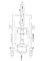
図2に示すように、ICチップ3の測定回路部10は、積分回路11、増幅回路12、比較回路13、遅延回路14、カウンタ回路15および発振回路16を備えている。
図2に示すように、ICチップ3の測定回路部10は、積分回路11、増幅回路12、比較回路13、遅延回路14、カウンタ回路15および発振回路16を備えている。
積分回路11は、オペアンプ11a、2つの容量11b・11cおよび3つのスイッチ11d~11fを備えた差動型積分回路であり、熱電対5の端子間の起電力により流れる電流を積分する。オペアンプ11aは、全差動型のオペアンプであり、オペアンプ11aの2つの入力端子は、積分回路11の差動入力を構成している。容量11bとスイッチ11dとは、オペアンプ11aの反転入力端子と非反転出力端子との間に並列接続されており、容量11cとスイッチ11eとは、オペアンプ11aの非反転入力端子と反転出力端子との間に並列接続されている。また、スイッチ11fは、オペアンプ11aの2つの入力端子間に設けられている。
容量11b・11cは可変容量であり、容量11b・11cの容量値を変化させることにより、積分回路11の積分時間が調整できるようになっている。また、スイッチ11d~11fのON/OFFは、後述するリセット信号Rによって制御され、スイッチ11d~11fがONすることにより、積分回路11を既定の状態に戻すことができる。
増幅回路12は、オペアンプ12aおよび4つの抵抗12b~12eを備えている。抵抗12bは、オペアンプ12aの反転入力端子と出力端子との間に接続されており、抵抗12cは、オペアンプ12aの非反転入力端子と接地との間に接続されている。抵抗12dは、オペアンプ11aの非反転出力端子とオペアンプ12aの反転入力端子との間に接続され、抵抗12eは、オペアンプ11aの反転出力端子とオペアンプ12aの非反転入力端子との間に接続されている。抵抗12b・12cは可変抵抗であり、抵抗12b・12cの抵抗値を変化させることにより、増幅回路12の増幅率を調整できるようになっている。
以上の構成により、積分回路11は、端子間の温度差に応じて熱電対5に発生する起電力により流れる電流を積分し、増幅回路12は、積分回路11の出力を増幅する。増幅回路12で増幅された信号は比較回路13で増幅出力基準値と比較され、比較回路13は、増幅回路12の出力が増幅出力基準値を超えた場合にリセット信号Rを出力する。
また、比較回路13は、熱電対5の端子のいずれの温度が高いかを示す判定信号Dも出力する。これにより、風向が熱電対5の端子間を結ぶ方向のいずれの方向であるかを判定できる。
リセット信号Rは、遅延回路14を介して、積分回路11およびカウンタ回路15に入力される。リセット信号Rによって、積分回路11は既定の状態に戻される。カウンタ回路15には、リセット信号Rの他に発振回路16からクロック信号CLが入力される。
カウンタ回路15および発振回路16は、リセット信号が出力される間隔に基づいて風速を計測する計測回路を構成する。カウンタ回路15は、リセット信号Rが出力される間隔において、クロック信号CLの立ち上がりエッジの数を数え続ける。カウンタ回路15にリセット信号Rが入力された場合、カウンタ回路15のカウント数は、図示しないレジスタ回路に取り込まれたのち既定の値に戻され、カウンタ回路15は、新たにカウントを開始する。
なお、カウンタ回路15が飽和した時にもカウント数は既定の値に戻され、飽和したことを示す信号がカウンタ回路15から出力される。
(風速の計算)
図3は、風速を測定するための測定回路部10の動作を示す図である。風速が一定であると仮定すると、積分回路11および増幅回路12の出力は、風向に応じて単調に増加または減少する。増幅回路12の出力が増幅出力基準値を超えた時に、比較回路13からリセット信号Rが出力される。
図3は、風速を測定するための測定回路部10の動作を示す図である。風速が一定であると仮定すると、積分回路11および増幅回路12の出力は、風向に応じて単調に増加または減少する。増幅回路12の出力が増幅出力基準値を超えた時に、比較回路13からリセット信号Rが出力される。
カウンタ回路15は、リセット信号Rが立ち上がってから次のリセット信号Rが立ち上がるまでの期間、クロック信号CLの立ち上がりエッジの数を数え、該期間におけるカウント数をレジスタ回路に記憶させる。これにより、レジスタ回路に記憶されたクロック数は、リセット信号Rが出力される間隔に対応する。例えば、組み合わせ表を参照することにより、上記クロック数を風速に読み替えることができる。
このように、測定回路部10は、リセット信号Rが出力される間隔に基づいて風速を計測することができる。
(本実施形態の効果)
このように、本実施形態では、ICチップ3単体で風速を測定可能であり、従来のように外部のフィルタ回路を必要としない。
このように、本実施形態では、ICチップ3単体で風速を測定可能であり、従来のように外部のフィルタ回路を必要としない。
また、本実施形態では、積分回路11を用いて測定回路部10を実現しているので、熱電対5の起電力が小さくても、正確に風速を測定することができる。そのため、ICチップ3を熱伝導率が高いセラミックディスクなどに実装する必要がない。また、ICチップ3をパッケージ4によって封止することにより、熱電対5の端子間における温度差が小さくなっても、問題は生じない。すなわち、通常のパッケージ4に風向風速を測定するためのICチップ3を封止することができるため、量産化が容易であり、風向風速計1の製造コストを低減することができる。
なお、ICチップ3をパッケージ4によって封止せずに、熱電対5がICチップ3の表面の温度分布によって起電力を発生するように構成してもよい。あるいは、熱電対5が基板2のICチップ3が実装されている面の裏面の温度分布によって起電力を発生するように構成してもよい。すなわち、風向風速計1は、ICチップ3の表面の温度分布または基板2の裏面の温度分布に基づいて、風向と風速とを測定することも可能である。
(他の特徴)
また、上記のように、積分回路11および増幅回路12は、それぞれ積分時間および増幅率を調整できるようになっている。そのため、瞬間的な風速の測定と平均的な風速の測定が同一の積分回路11および増幅回路12を用いて実現可能である。なお、リセット信号Rの長さ(出力される間隔)は、積分回路11の積分時間に応じて変える必要があるため、本実施形態では、遅延回路14によってリセット信号Rの長さを調整可能としている。
また、上記のように、積分回路11および増幅回路12は、それぞれ積分時間および増幅率を調整できるようになっている。そのため、瞬間的な風速の測定と平均的な風速の測定が同一の積分回路11および増幅回路12を用いて実現可能である。なお、リセット信号Rの長さ(出力される間隔)は、積分回路11の積分時間に応じて変える必要があるため、本実施形態では、遅延回路14によってリセット信号Rの長さを調整可能としている。
また、風速が微弱で熱電対5からの起電力が小さい場合には、比較回路13からリセット信号Rが出力される間隔が広がるため、カウンタ回路15が飽和しやすくなる。そこで、本実施形態では、発振回路16からのクロック信号CLの周波数を可変としている。クロック信号CLの周波数は、分周回路などの周波数調整手段によって調整される。熱電対5の端子間の温度差が小さくなるほど、リセット信号Rの出力間隔が長くなるので、クロック信号CLの周波数を遅くすることで、カウンタ回路15が飽和することを防ぐことができる。また、用途に応じて、クロック信号CLの周波数を変更することで、風向風速計1の測定精度を変更することもできる。
上記のように、熱電対5の両端を積分回路11の差動入力端子に接続することで、熱電対5の起電力を電流に変換することが可能となる。このとき、ICチップ3内部に適切な素材で熱電対5を形成した場合には、Mottの関係式より、熱電対5のゼーベック係数は周囲温度に依存せず、熱電対5の端子間の温度差にのみ依存するようになる。
より詳細には、Mottの関係式よりゼーベック係数S(V/K)と抵抗率ρ(Ω・m)との間には、
S=αρ
という関係が成り立つ。つまり、ゼーベック係数の温度変化は抵抗率の温度変化に等しくなる。
S=αρ
という関係が成り立つ。つまり、ゼーベック係数の温度変化は抵抗率の温度変化に等しくなる。
また、熱電対5の端子間の温度差がΔTのときの起電力Vは、
V=SΔT
で表される。そのため、熱電対5の端子間に流れる電流Iは、
I=V/R=(αρΔT)/(ρL/A)=αAΔT/L
となり、温度差ΔTのみに比例する。つまり、電流Iは周囲温度に依存しない。よって、熱電対5の端子間の起電力により流れる電流を用いることにより、周囲温度を考慮することなく温度測定を行うことができる。この場合、周囲温度に基づいて熱電対5の感度を補正しなくてもよいので、周囲温度を測定するための温度計が不要となる。
V=SΔT
で表される。そのため、熱電対5の端子間に流れる電流Iは、
I=V/R=(αρΔT)/(ρL/A)=αAΔT/L
となり、温度差ΔTのみに比例する。つまり、電流Iは周囲温度に依存しない。よって、熱電対5の端子間の起電力により流れる電流を用いることにより、周囲温度を考慮することなく温度測定を行うことができる。この場合、周囲温度に基づいて熱電対5の感度を補正しなくてもよいので、周囲温度を測定するための温度計が不要となる。
また、積分回路11は、熱電対5に発生する起電力により流れる電流の積分を行うために容量11b・11cを用いているので、容量11b・11cの絶対値のバラツキは、電流値すなわち風速のバラツキと等価である。そのため、積分回路11は、容量11b・11cの絶対値のバラツキを補正するために、冗長な容量を有していることが好ましい。容量の相対値の精度は容量の絶対値の精度よりも正確である。
そこで、積分回路11と同じ構成の積分回路であるレプリカ回路を設けることが好ましい。このレプリカ回路で容量11b・11cの絶対値のバラツキを測定することにより、容量の補正値が計算される。
(変形例)
上述した実施形態では、ICチップ3が基板2に実装されていたが、本発明はこれに限定されない。ICチップ3を、フィルムやプラスチック面に実装してもよい。
上述した実施形態では、ICチップ3が基板2に実装されていたが、本発明はこれに限定されない。ICチップ3を、フィルムやプラスチック面に実装してもよい。
また、上述した実施形態では、熱電対5およびヒータ6を、ICチップ3内部に実装していたが、ICチップ3の外部に設けてもよい。例えば、熱電対5およびヒータ6を基板に直接実装して、基板の裏面の温度分布に基づいて風速を測定してもよい。
また、上述した実施形態では、熱電対5をICチップ3の内縁に沿って設けていたが、熱電対5をICチップ3の対角線上または該対角線に沿って設けてもよい。
また、上述した実施形態では、積分回路11の出力を増幅回路12によって増幅して、増幅した出力を比較回路13において増幅出力基準値と比較する構成であったが、これに限定されない。増幅回路12を設けずに、積分回路11の出力を基準値と比較する構成であってもよい。
また、上述した実施形態では、風向風速計1は、端子間の方向が互いに異なる熱電対5を複数備える構成であったが、熱電対5を1つのみ備える構成であってもよい。その場合、風向風速計1は、風向を測定せず、風速のみを測定してもよい。
(付記事項)
本発明は上述した実施形態に限定されるものではなく、請求項に示した範囲で種々の変更が可能である。すなわち、請求項に示した範囲で適宜変更した技術的手段を組み合わせて得られる実施形態についても本発明の技術的範囲に含まれる。
本発明は上述した実施形態に限定されるものではなく、請求項に示した範囲で種々の変更が可能である。すなわち、請求項に示した範囲で適宜変更した技術的手段を組み合わせて得られる実施形態についても本発明の技術的範囲に含まれる。
以上のように、本発明に係る風速計は、前記積分回路の出力を増幅する増幅回路をさらに備え、前記比較回路は、前記増幅回路によって増幅された前記積分回路の出力を増幅出力基準値と比較し、該増幅された前記積分回路の出力が前記増幅出力基準値を超えた場合に、前記リセット信号を出力することが好ましい。
上記の構成によれば、積分回路の出力は増幅回路によって増幅されるので、リセット信号が出力される間隔が短くなる。そのため、計測回路としてカウンタ回路を用いた場合に、カウンタ回路が飽和しにくくなり、測定が容易になる。
本発明に係る風速計では、前記増幅回路の増幅率が可変であることが好ましい。
本発明に係る風速計では、前記積分回路の積分時間が可変であることが好ましい。
上記の構成によれば、瞬間的な風速の測定と平均的な風速の測定が同一の積分回路および増幅回路を用いて実現可能となる。
本発明に係る風速計では、前記計測回路は、クロック信号を発生する発振回路と、前記リセット信号が出力される間隔において、前記クロック信号をカウントするカウンタ回路と、を備えることが好ましい。
上記の構成によれば、クロック信号の周波数、および、リセット信号が出力される間隔におけるカウンタ回路のカウント数から、リセット信号が出力される間隔が求められるので、風速を計測することができる。
本発明に係る風速計では、レジスタ回路をさらに備え、前記カウンタ回路は、前記リセット信号が出力されると、既定の状態に戻されるとともに、カウント数を前記レジスタ回路に出力することが好ましい。
上記の構成によれば、カウンタ回路は、リセット信号によって既定の状態に戻されるので、ビット数の小さいカウンタ回路を使用することができる。
本発明に係る風速計では、前記クロック信号の周波数を調整する周波数調整手段を備えることが好ましい。
上記の構成によれば、クロック信号の周波数を変更することで、風速計の測定精度を変更することができる。
本発明に係る風速計では、前記周波数調整手段は、前記熱電対の端子間の温度差に応じて、前記クロック信号の周波数を調整することが好ましい。
熱電対の端子間の温度差が小さくなるほど、リセット信号の出力間隔が長くなるので、周波数調整手段によってクロック信号の周波数を遅くすることで、カウンタ回路が飽和することを防ぐことができる。
本発明に係る風速計では、前記積分回路は差動型積分回路であり、前記熱電対の前記2つの端子は、前記積分回路の差動入力端子にそれぞれ接続されていることが好ましい。
上記の構成によれば、熱電対の各端子を積分回路の差動入力端子に接続することで、熱電対からの起電力は電流に変換することが可能となる。これにより、熱電対の感度が周囲温度に依存しなくなるので、熱電対の感度を補正する必要がなくなる。
本発明に係る風速計では、前記リセット信号の長さを調整するための遅延回路を備えていることが好ましい。
上記の構成によれば、積分回路の積分時間に応じてリセット信号の長さを調整することができる。
本発明に係る風速計では、前記比較回路は、前記2つの端子のいずれの温度が高いかを示す信号を出力することが好ましい。
上記の構成によれば、風速計は、風向が熱電対の端子間を結ぶ方向のいずれの方向であるかを判定できる。
本発明に係る風速計では、前記熱電対を複数備え、各熱電対の端子間の方向が、互いに異なることが好ましい。
上記の構成によれば、各熱電対の端子間の温度差に基づいて、風向を正確に測定できる。
本発明に係る風速計では、前記積分回路と同じ構成の積分回路であるレプリカ回路を備えていることが好ましい。
上記の構成によれば、レプリカ回路で積分容量の絶対値のバラツキを測定することにより、積分回路の積分容量の絶対値のバラツキを補正することができる。
本発明に係る風速計では、周囲温度を測定するための温度計をさらに備えることが好ましい。
本発明に係る風速計では、前記温度計により測定した前記周囲温度を用いて熱電対の感度変化を補正することが好ましい。
上記の構成によれば、熱電対の感度が周囲温度により変化した場合には、温度計で測定した周囲温度を用いて、熱電対の感度を補正することができる。
本発明に係る風速計では、前記各回路は、ICチップに内蔵されていることが好ましい。
本発明に係る風速計では、前記熱電対と前記ヒータとが、前記ICチップ内部に実装されていることが好ましい。
上記の構成によれば、風速計を容易に小型化することができる。
本発明に係る風速計では、前記熱電対は、前記ICチップの内縁に沿って設けられていることが好ましい。
本発明に係る風速計では、前記熱電対は、前記ICチップの対角線上または該対角線に沿って設けられていることが好ましい。
上記の構成によれば、端子間の方向が互いに異なる熱電対が複数設けられている場合、各熱電対の端子間の温度差に基づいて、風向を正確に測定できる。
本発明に係る風速計では、前記熱電対は、前記ICチップの表面の温度分布によって起電力を発生することが好ましい。
上記の構成によれば、ICチップの表面の温度分布から風速を測定することができる。
本発明に係る風速計では、前記ICチップはパッケージによって封止されており、前記熱電対は、前記パッケージの表面の温度分布によって起電力を発生することが好ましい。
上記の構成によれば、パッケージの表面の温度分布から風速を測定することができる。
本発明に係る風速計では、前記ICチップは、基板に実装されており、前記熱電対は、前記基板の前記ICチップが実装されている面の裏面の温度分布によって起電力を発生することが好ましい。
上記の構成によれば、基板の裏面の温度分布から風速を測定することができる。
なお、本発明は以下のように表現できる。
本発明に係る風向風速計は、熱電対を用いた風向風速計であって、風速に応じた温度差を作り出すために熱を発生させるヒータと、前記熱電対からの起電力による信号を積分する積分回路と、前記積分回路の出力を増幅するための増幅回路と、前記増幅回路の出力を基準値と比較しリセット信号を出力する比較回路と、前記リセット信号が出力される間隔を調べるカウント回路と、を備えることを特徴とする。
本発明に係る風向風速計では、前記熱電対と前記ヒータをIC内部に実装することが好ましい。
本発明に係る風向風速計では、前記熱電対がICの内縁に置かれていることが好ましい。
本発明に係る風向風速計では、向かい合う前記熱電対の起電力の差を検出することで風向を測定することが好ましい。
本発明に係る風向風速計では、前記熱電対がICの対角線上に置かれていることが好ましい。
本発明に係る風向風速計では、前記熱電対の両端を前記積分回路の差動入力に接続して起電力を電流に変換することで前記熱電対の感度が前記ICの周囲温度に依存しないようにすることが好ましい。
本発明に係る風向風速計では、前記ICを直接基板に実装し、風によるIC表面もしくは基板裏面の温度分布から風向と風速とを測定することが好ましい。
本発明に係る風向風速計では、前記ICをパッケージに封止し、風によるパッケージ表面の温度分布から風向と風速とを測定することが好ましい。
本発明に係る風向風速計では、前記積分回路の積分時間と前記増幅回路の増幅率を可変とするために前記積分回路の容量値と前記増幅回路の抵抗値が可変であることが好ましい。
本発明に係る風向風速計では、前記比較回路は風向を検知するための信号も出力することが好ましい。
本発明に係る風向風速計では、風速に応じて前記熱電対の端子間の温度差が変わった場合には前記カウンタ回路が飽和しないように入力されるクロック周波数を調整する機能を備えていることが好ましい。
本発明に係る風向風速計では、前記カウンタ回路に入力される前記クロック周波数を変更することで測定精度を変更することが好ましい。
本発明に係る風向風速計では、前記リセット信号は、前記積分回路と前記カウンタ回路を既定の状態に戻すための信号であるとともに前記カウンタ回路のカウント数をレジスタに取り込むための信号でもあることが好ましい。
本発明に係る風向風速計では、前記リセット信号の長さを調整するための遅延回路を備えていることが好ましい。
本発明に係る風向風速計では、前記積分回路の積分容量の絶対値のバラツキを補正するために前記積分回路と同じ構成の積分回路を有するレプリカ回路を備えることが好ましい。
本発明に係る風向風速計では、温度計を内蔵することで周囲温度の測定も行うことが好ましい。
本発明に係る風向風速計では、前記温度計により測定した前記周囲温度を用いて熱電対の感度変化を補正することが好ましい。
本発明は、熱電対を用いた風向風速計に利用することができる。
1 風向風速計(風速計)
2 基板
3 ICチップ
4 パッケージ
5 熱電対
6 ヒータ
10 測定回路部
11 積分回路
11a オペアンプ
11b 容量
11c 容量
11d スイッチ
11e スイッチ
11f スイッチ
12 増幅回路
12a オペアンプ
12b 抵抗
12c 抵抗
12d 抵抗
12e 抵抗
13 比較回路
14 遅延回路
15 カウンタ回路
16 発振回路
CL クロック信号
D 判定信号
R リセット信号
2 基板
3 ICチップ
4 パッケージ
5 熱電対
6 ヒータ
10 測定回路部
11 積分回路
11a オペアンプ
11b 容量
11c 容量
11d スイッチ
11e スイッチ
11f スイッチ
12 増幅回路
12a オペアンプ
12b 抵抗
12c 抵抗
12d 抵抗
12e 抵抗
13 比較回路
14 遅延回路
15 カウンタ回路
16 発振回路
CL クロック信号
D 判定信号
R リセット信号
Claims (22)
- 2つの端子間の温度差による起電力を発生する熱電対と、熱を発生するヒータと、を備える風速計であって、
前記熱電対からの起電力に応じた信号を積分する積分回路と、
前記積分回路の出力を基準値と比較し、前記積分回路の出力が前記基準値を超えた場合に、前記積分回路を既定の状態に戻すリセット信号を出力する比較回路と、
前記リセット信号が出力される間隔に基づいて風速を計測する計測回路と、
を備えることを特徴とする風速計。 - 請求項1に記載の風速計であって、
前記積分回路の出力を増幅する増幅回路をさらに備え、
前記比較回路は、前記増幅回路によって増幅された前記積分回路の出力を増幅出力基準値と比較し、該増幅された前記積分回路の出力が前記増幅出力基準値を超えた場合に、前記リセット信号を出力することを特徴とする風速計。 - 請求項2に記載の風速計であって、
前記増幅回路の増幅率が可変であることを特徴とする風速計。 - 請求項1~3のいずれか1項に記載の風速計であって、
前記積分回路の積分時間が可変であることを特徴とする風速計。 - 請求項1~4のいずれか1項に記載の風速計であって、
前記計測回路は、
クロック信号を発生する発振回路と、
前記リセット信号が出力される間隔において、前記クロック信号をカウントするカウンタ回路と、
を備えることを特徴とする風速計。 - 請求項5に記載の風速計であって、
レジスタ回路をさらに備え、
前記カウンタ回路は、前記リセット信号が出力されると、既定の状態に戻されるとともに、カウント数を前記レジスタ回路に出力することを特徴とする風速計。 - 請求項5または6に記載の風速計であって、
前記クロック信号の周波数を調整する周波数調整手段を備えることを特徴とする風速計。 - 請求項7に記載の風速計であって、
前記周波数調整手段は、前記熱電対の端子間の温度差に応じて、前記クロック信号の周波数を調整することを特徴とする風速計。 - 請求項1~8のいずれか1項に記載の風速計であって、
前記積分回路は差動型積分回路であり、
前記熱電対の前記2つの端子は、前記積分回路の差動入力端子にそれぞれ接続されていることを特徴とする風速計。 - 請求項1~9のいずれか1項に記載の風速計であって、
前記リセット信号の長さを調整するための遅延回路を備えていることを特徴とする風速計。 - 請求項1~10のいずれか1項に記載の風速計であって、
前記比較回路は、前記2つの端子のいずれの温度が高いかを示す信号を出力することを特徴とする風速計。 - 請求項1~11のいずれか1項に記載の風速計であって、
前記熱電対を複数備え、
各熱電対の端子間の方向が、互いに異なることを特徴とする風速計。 - 請求項1~12のいずれか1項に記載の風速計であって、
前記積分回路と同じ構成の積分回路であるレプリカ回路を備えていることを特徴とする風速計。 - 請求項1~13のいずれか1項に記載の風速計であって、
周囲温度を測定するための温度計をさらに備えることを特徴とする風速計。 - 請求項14に記載の風速計であって、
前記温度計により測定した前記周囲温度を用いて熱電対の感度変化を補正することを特徴とする風速計。 - 請求項1~15のいずれか1項に記載の風速計であって、
前記各回路は、ICチップに内蔵されていることを特徴とする風速計。 - 請求項16に記載の風速計であって、
前記熱電対と前記ヒータとが、前記ICチップ内部に実装されていることを特徴とする風速計。 - 請求項17に記載の風速計であって、
前記熱電対は、前記ICチップの内縁に沿って設けられていることを特徴とする風速計。 - 請求項17に記載の風速計であって、
前記熱電対は、前記ICチップの対角線上または該対角線に沿って設けられていることを特徴とする風速計。 - 請求項17~19のいずれか1項に記載の風速計であって、
前記熱電対は、前記ICチップの表面の温度分布によって起電力を発生することを特徴とする風速計。 - 請求項17~19のいずれか1項に記載の風速計であって、
前記ICチップはパッケージによって封止されており、
前記熱電対は、前記パッケージの表面の温度分布によって起電力を発生することを特徴とする風速計。 - 請求項17~19のいずれか1項に記載の風速計であって、
前記ICチップは、基板に実装されており、
前記熱電対は、前記基板の前記ICチップが実装されている面の裏面の温度分布によって起電力を発生することを特徴とする風速計。
Applications Claiming Priority (2)
| Application Number | Priority Date | Filing Date | Title |
|---|---|---|---|
| JP2012-059410 | 2012-03-15 | ||
| JP2012059410A JP2013195085A (ja) | 2012-03-15 | 2012-03-15 | 風速計 |
Publications (1)
| Publication Number | Publication Date |
|---|---|
| WO2013137336A1 true WO2013137336A1 (ja) | 2013-09-19 |
Family
ID=49161241
Family Applications (1)
| Application Number | Title | Priority Date | Filing Date |
|---|---|---|---|
| PCT/JP2013/057049 Ceased WO2013137336A1 (ja) | 2012-03-15 | 2013-03-13 | 風速計 |
Country Status (3)
| Country | Link |
|---|---|
| JP (1) | JP2013195085A (ja) |
| TW (1) | TW201346264A (ja) |
| WO (1) | WO2013137336A1 (ja) |
Cited By (3)
| Publication number | Priority date | Publication date | Assignee | Title |
|---|---|---|---|---|
| CN106461700A (zh) * | 2014-06-03 | 2017-02-22 | 株式会社电装 | 风向计、风向风量计以及移动方向测定计 |
| CN113466488A (zh) * | 2021-07-19 | 2021-10-01 | 东南大学 | 二维温度平衡模式mems风速风向传感器及其制备方法 |
| CN114895064A (zh) * | 2022-06-21 | 2022-08-12 | 广州极飞科技股份有限公司 | 温度控制电路、环境风信息测量装置及系统 |
Families Citing this family (5)
| Publication number | Priority date | Publication date | Assignee | Title |
|---|---|---|---|---|
| CN105319387B (zh) * | 2015-12-03 | 2019-12-03 | 东南大学 | 一种交流自加热式风速风向传感器及其测量方法 |
| TWI737858B (zh) * | 2017-11-17 | 2021-09-01 | 鴻海精密工業股份有限公司 | 具有風速偵測功能的電子裝置及風速偵測方法 |
| CN108226568A (zh) * | 2017-12-20 | 2018-06-29 | 东南大学 | 基于八边形热敏电阻结构的风速风向传感器及其制备方法 |
| CN108169509A (zh) * | 2017-12-20 | 2018-06-15 | 东南大学 | 基于八边形热电堆结构的风速风向传感器及其制备方法 |
| CN107907707B (zh) * | 2017-12-28 | 2019-07-12 | 东南大学 | 一种基于双层热电堆结构的风速风向传感器及检测方法 |
Citations (3)
| Publication number | Priority date | Publication date | Assignee | Title |
|---|---|---|---|---|
| JPS56107162A (en) * | 1980-01-31 | 1981-08-25 | Ogasawara Keiki Seisakusho:Kk | Periodical measurenent-type wind velocity measurement |
| JP2001296156A (ja) * | 2000-04-13 | 2001-10-26 | Yazaki Corp | 流量計測装置及び電子式流量メータ |
| JP2004061412A (ja) * | 2002-07-31 | 2004-02-26 | Horiba Ltd | 流体センサ |
Family Cites Families (1)
| Publication number | Priority date | Publication date | Assignee | Title |
|---|---|---|---|---|
| NL8702229A (nl) * | 1987-09-18 | 1989-04-17 | Bronkhorst High Tech Bv | Richtingsgevoelige stroomsnelheidsmeter. |
-
2012
- 2012-03-15 JP JP2012059410A patent/JP2013195085A/ja active Pending
-
2013
- 2013-03-13 WO PCT/JP2013/057049 patent/WO2013137336A1/ja not_active Ceased
- 2013-03-14 TW TW102109097A patent/TW201346264A/zh unknown
Patent Citations (3)
| Publication number | Priority date | Publication date | Assignee | Title |
|---|---|---|---|---|
| JPS56107162A (en) * | 1980-01-31 | 1981-08-25 | Ogasawara Keiki Seisakusho:Kk | Periodical measurenent-type wind velocity measurement |
| JP2001296156A (ja) * | 2000-04-13 | 2001-10-26 | Yazaki Corp | 流量計測装置及び電子式流量メータ |
| JP2004061412A (ja) * | 2002-07-31 | 2004-02-26 | Horiba Ltd | 流体センサ |
Cited By (6)
| Publication number | Priority date | Publication date | Assignee | Title |
|---|---|---|---|---|
| CN106461700A (zh) * | 2014-06-03 | 2017-02-22 | 株式会社电装 | 风向计、风向风量计以及移动方向测定计 |
| EP3153868A4 (en) * | 2014-06-03 | 2017-04-12 | Denso Corporation | Wind direction meter, wind direction and flow meter, and movement direction meter |
| US10345328B2 (en) | 2014-06-03 | 2019-07-09 | Denso Corporation | Wind direction meter, wind direction/flow meter, and movement direction meter |
| CN113466488A (zh) * | 2021-07-19 | 2021-10-01 | 东南大学 | 二维温度平衡模式mems风速风向传感器及其制备方法 |
| CN113466488B (zh) * | 2021-07-19 | 2022-05-27 | 东南大学 | 二维温度平衡模式mems风速风向传感器及其制备方法 |
| CN114895064A (zh) * | 2022-06-21 | 2022-08-12 | 广州极飞科技股份有限公司 | 温度控制电路、环境风信息测量装置及系统 |
Also Published As
| Publication number | Publication date |
|---|---|
| TW201346264A (zh) | 2013-11-16 |
| JP2013195085A (ja) | 2013-09-30 |
Similar Documents
| Publication | Publication Date | Title |
|---|---|---|
| WO2013137336A1 (ja) | 風速計 | |
| CN101680788B (zh) | 热式流量计 | |
| CN103051285B (zh) | 用于修正压阻式振荡器的频率的温度相关性的电路和方法 | |
| US8874387B2 (en) | Air flow measurement device and air flow correction method | |
| CN111542760A (zh) | 用于校正分流电阻器的电流值的系统和方法 | |
| CN102976261B (zh) | 在管芯上结合附加电路的mems气流传感器管芯 | |
| CN100405066C (zh) | 流速传感器 | |
| CN106840287B (zh) | 流量传感器、流量计及流量检测方法 | |
| JP3410562B2 (ja) | 温度・風速測定装置 | |
| US20140278184A1 (en) | Zero Deadband Processing for Velocity Transmitters | |
| JPH09318412A (ja) | 熱式流速センサ | |
| JP2004309202A (ja) | 風速、風量センサ | |
| CN209250231U (zh) | 温度保护电路和用于其的温度检测装置 | |
| JP3454265B2 (ja) | 熱式流速センサ | |
| CN106644139A (zh) | 一种基于铂电阻的测温装置 | |
| JP2012134910A5 (ja) | ||
| Sauter et al. | Thermal flow sensors based on printed circuit board technology | |
| CN115824333B (zh) | 热式气体质量流量计的介质温度的检测电路、方法及设备 | |
| CN212540498U (zh) | 一种用于毫米波功率计的自平衡电桥电路 | |
| JPS63314912A (ja) | 発振型検知回路とその製造方法 | |
| JP2000214030A (ja) | 圧力センサ回路 | |
| JPH04332867A (ja) | 熱線風速計 | |
| JPH03279866A (ja) | 風速センサ | |
| JPS5920658Y2 (ja) | 熱伝導型真空ゲ−ジの検出回路 | |
| JPH048734B2 (ja) |
Legal Events
| Date | Code | Title | Description |
|---|---|---|---|
| 121 | Ep: the epo has been informed by wipo that ep was designated in this application |
Ref document number: 13760416 Country of ref document: EP Kind code of ref document: A1 |
|
| NENP | Non-entry into the national phase |
Ref country code: DE |
|
| 122 | Ep: pct application non-entry in european phase |
Ref document number: 13760416 Country of ref document: EP Kind code of ref document: A1 |