WO2013137249A1 - 鉄鋼材の製造方法 - Google Patents
鉄鋼材の製造方法 Download PDFInfo
- Publication number
- WO2013137249A1 WO2013137249A1 PCT/JP2013/056800 JP2013056800W WO2013137249A1 WO 2013137249 A1 WO2013137249 A1 WO 2013137249A1 JP 2013056800 W JP2013056800 W JP 2013056800W WO 2013137249 A1 WO2013137249 A1 WO 2013137249A1
- Authority
- WO
- WIPO (PCT)
- Prior art keywords
- base material
- steel material
- cooling
- austenite
- strain
- Prior art date
- Legal status (The legal status is an assumption and is not a legal conclusion. Google has not performed a legal analysis and makes no representation as to the accuracy of the status listed.)
- Ceased
Links
Images











Classifications
-
- C—CHEMISTRY; METALLURGY
- C21—METALLURGY OF IRON
- C21D—MODIFYING THE PHYSICAL STRUCTURE OF FERROUS METALS; GENERAL DEVICES FOR HEAT TREATMENT OF FERROUS OR NON-FERROUS METALS OR ALLOYS; MAKING METAL MALLEABLE, e.g. BY DECARBURISATION OR TEMPERING
- C21D8/00—Modifying the physical properties of ferrous metals or ferrous alloys by deformation combined with, or followed by, heat treatment
-
- B—PERFORMING OPERATIONS; TRANSPORTING
- B23—MACHINE TOOLS; METAL-WORKING NOT OTHERWISE PROVIDED FOR
- B23K—SOLDERING OR UNSOLDERING; WELDING; CLADDING OR PLATING BY SOLDERING OR WELDING; CUTTING BY APPLYING HEAT LOCALLY, e.g. FLAME CUTTING; WORKING BY LASER BEAM
- B23K20/00—Non-electric welding by applying impact or other pressure, with or without the application of heat, e.g. cladding or plating
- B23K20/12—Non-electric welding by applying impact or other pressure, with or without the application of heat, e.g. cladding or plating the heat being generated by friction; Friction welding
- B23K20/122—Non-electric welding by applying impact or other pressure, with or without the application of heat, e.g. cladding or plating the heat being generated by friction; Friction welding using a non-consumable tool, e.g. friction stir welding
-
- C—CHEMISTRY; METALLURGY
- C21—METALLURGY OF IRON
- C21D—MODIFYING THE PHYSICAL STRUCTURE OF FERROUS METALS; GENERAL DEVICES FOR HEAT TREATMENT OF FERROUS OR NON-FERROUS METALS OR ALLOYS; MAKING METAL MALLEABLE, e.g. BY DECARBURISATION OR TEMPERING
- C21D9/00—Heat treatment, e.g. annealing, hardening, quenching or tempering, adapted for particular articles; Furnaces therefor
- C21D9/50—Heat treatment, e.g. annealing, hardening, quenching or tempering, adapted for particular articles; Furnaces therefor for welded joints
-
- C—CHEMISTRY; METALLURGY
- C21—METALLURGY OF IRON
- C21D—MODIFYING THE PHYSICAL STRUCTURE OF FERROUS METALS; GENERAL DEVICES FOR HEAT TREATMENT OF FERROUS OR NON-FERROUS METALS OR ALLOYS; MAKING METAL MALLEABLE, e.g. BY DECARBURISATION OR TEMPERING
- C21D2211/00—Microstructure comprising significant phases
- C21D2211/001—Austenite
-
- C—CHEMISTRY; METALLURGY
- C21—METALLURGY OF IRON
- C21D—MODIFYING THE PHYSICAL STRUCTURE OF FERROUS METALS; GENERAL DEVICES FOR HEAT TREATMENT OF FERROUS OR NON-FERROUS METALS OR ALLOYS; MAKING METAL MALLEABLE, e.g. BY DECARBURISATION OR TEMPERING
- C21D2211/00—Microstructure comprising significant phases
- C21D2211/008—Martensite
-
- C—CHEMISTRY; METALLURGY
- C21—METALLURGY OF IRON
- C21D—MODIFYING THE PHYSICAL STRUCTURE OF FERROUS METALS; GENERAL DEVICES FOR HEAT TREATMENT OF FERROUS OR NON-FERROUS METALS OR ALLOYS; MAKING METAL MALLEABLE, e.g. BY DECARBURISATION OR TEMPERING
- C21D7/00—Modifying the physical properties of iron or steel by deformation
- C21D7/02—Modifying the physical properties of iron or steel by deformation by cold working
- C21D7/04—Modifying the physical properties of iron or steel by deformation by cold working of the surface
-
- C—CHEMISTRY; METALLURGY
- C21—METALLURGY OF IRON
- C21D—MODIFYING THE PHYSICAL STRUCTURE OF FERROUS METALS; GENERAL DEVICES FOR HEAT TREATMENT OF FERROUS OR NON-FERROUS METALS OR ALLOYS; MAKING METAL MALLEABLE, e.g. BY DECARBURISATION OR TEMPERING
- C21D9/00—Heat treatment, e.g. annealing, hardening, quenching or tempering, adapted for particular articles; Furnaces therefor
- C21D9/46—Heat treatment, e.g. annealing, hardening, quenching or tempering, adapted for particular articles; Furnaces therefor for sheet metals
Definitions
- An embodiment of the present invention relates to a method for manufacturing a steel material, and relates to a method for manufacturing a steel material that manufactures a steel material having increased strength and ductility by processing a base material of the steel material.
- Friction Stir Welding has various excellent properties including joint properties, and has been applied to aluminum alloys in various industrial fields soon after being developed.
- FSW Friction Stir Welding
- One embodiment of the present invention has been made in view of the above problems, and an object thereof is to provide a method for producing a steel material capable of producing a steel material having high ductility while having high strength. To do.
- a heating step of heating A above point C1 is the temperature at which the base material of the steel material austenite appears
- the M f point is the temperature at which the tissue entirely is the martensite matrix steel
- the amount of strain estimated to drop below the temperature at which the material is used and in the region where martensite is generated in the base material on the continuous cooling transformation diagram (CCT diagram)
- a method of manufacturing a steel material including a cooling step of cooling a base material subjected to a heating step and a strain introduction step to a temperature higher than the Mf point at a cooling rate estimated to intersect lines extrapolating a cooling curve. is there.
- the steel base material is heated to the AC1 point or higher, which is the temperature at which austenite appears. Thereby, austenite can appear in the base material.
- strain introduction step the distortion amount of M f point organization entire preform is at a temperature of the martensite is estimated that falls below the temperature at which the steel material is used to introduce the base material. For this reason, it is possible to prevent the entire structure of the steel material from becoming martensite when the steel material is cooled to a temperature at which the steel material is used, such as room temperature.
- the region where ferrite or pearlite is generated also expands.
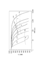
- a continuous cooling transformation diagram showing the phase transformation when the steel base material is continuously cooled on the coordinate plane of time and temperature is shown.
- it further includes an inspection process for inspecting the structure of the base material that has been subjected to the cooling process, and it is found that no austenite remains in the base material structure and martensite is generated in the inspection process.
- an inspection process for inspecting the structure of the base material that has been subjected to the cooling process, and it is found that no austenite remains in the base material structure and martensite is generated in the inspection process.
- the inspection process which inspects the structure
- the M f point is not sufficiently lowered with respect to the temperature at which the steel material is used. Is estimated. Therefore, when manufacturing the steel material next time, an increase in the amount of strain to be introduced into the base material in the strain introduction process, and the addition amount of austenite stabilizing elements such as C, Mn, Ni, Cr and Mo to the base material At least one of the increases is performed. Thereby, the Mf point can be sufficiently lowered with respect to the temperature at which the steel material is used, and austenite can remain.
- the base material is heated and the strain is introduced into the base material by rotating the rotary tool while bringing the tip of the rod-shaped rotary tool into contact with the base material, and the cooling step. Then, at least one of moving the tip of the rotary tool while rotating the rotary tool while the tip of the rotary tool is in contact with the base material and separating the tip of the rotary tool from the base material.
- the base material can be cooled.
- the base material is heated and the strain is introduced into the base material by rotating the rotary tool while bringing the tip of the rod-shaped rotary tool into contact with the base material.
- the tip of the rotating tool is moved while the rotating tool is rotated while the tip of the rotating tool is in contact with the base material, and the tip of the rotating tool is separated from the base material.
- the base material is cooled by at least one of them.
- FIG. 1 is a state diagram of a steel material 1. It is a CCT figure of steel material 2. It is a figure which shows the effect
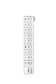
- FIG. 3 is a table showing the chemical composition of steel material 1 in Experimental Example 1.
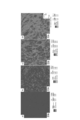
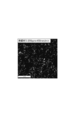
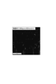
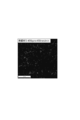
- (A)-(d) shows the phase map of the stirring part of the steel material 1 in Experimental Example 1, and shows the phase map of the stirring part at the rotation speeds of 100 rpm, 200 rpm, 300 rpm, and 400 rpm, respectively.
- FIG. 6 is a diagram showing an EBSD phase distribution image of a stirring portion at a rotational speed of 400 rpm and a joining speed of 100 mm / min of the steel material 2 in Experimental Example 2.
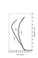
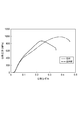
- FIG. 7 is a diagram showing an EBSD phase distribution image of a stirring portion at a rotation speed of 400 rpm and a joining speed of 400 mm / min of the steel material 2 in Experimental Example 2. It is a graph which shows the base material of the steel material 2 in Experimental example 2, and the nominal stress-nominal strain curve at a rotational speed of 400 rpm and a joining speed of 400 mm / min. It is a figure which shows the fcc orientation map of the base material of the steel material 3 in Experimental example 2.
- FIG. 10 is a diagram showing an fcc orientation map of a base material at a rotational speed of 200 rpm and a joining speed of 400 mm / min of the steel material 3 in Experimental Example 2.
- FIG. 10 is a diagram showing an fcc orientation map of a base material at a rotational speed of 300 rpm and a joining speed of 400 mm / min of the steel material 3 in Experimental Example 2.
- FIG. 10 is a diagram showing an fcc orientation map of a base material at a rotational speed of 400 rpm and a joining speed of 400 mm / min of the steel material 3 in Experimental Example 2. It is a table
- FIG. It is a graph which shows the XRD pattern of the stirring part in the different rotational speed in Experimental example 3.
- the base materials 1a and 1b for example, ferritic steel, Cr—Mo steel and high carbon steel can be used.
- the additive 10 can be filled on the stirring portion 20 of the base materials 1a and 1b depending on the situation.
- powdery or granular C, Mn, Ni, Cr, Mo, W, V, Ta, or the like can be used.
- C, Mn, Ni, Cr, Mo, W, V, Ta, etc. in the form of a plate or a thin sheet are formed on the base materials 1 a and 1 b other than the stirrer 20 or the stirrer 20. It may be arranged on the surface.
- the additive 10 is not restricted to the stirring part 20, You may be added to the whole composition of the base materials 1a and 1b.
- the stirring unit 20 is forcibly cooled from the outside by circulating a cooled refrigerant on the upper surface or the lower surface of the stirring unit 20.
- Cooling means may be arranged.
- a cooling means in this case, for example, liquid CO 2 , liquid nitrogen, water, and the like can be supplied to the stirring unit 20.
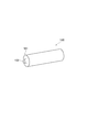
- a rotating tool 100 as shown in FIG. 2 is prepared.
- the rotary tool 100 has a substantially cylindrical shape, and includes a substantially cylindrical probe 102 having a smaller diameter than the shoulder 101 at the tip.
- the material of the rotary tool 100 is made of, for example, tool steel such as SKD61 steel compliant with Japanese Industrial Standards, cemented carbide containing tungsten carbide (WC) as a main component, or ceramic such as Si 3 N 4. Can be.
- C1-point A of each composition of the steel material can be obtained by the following equation (1).
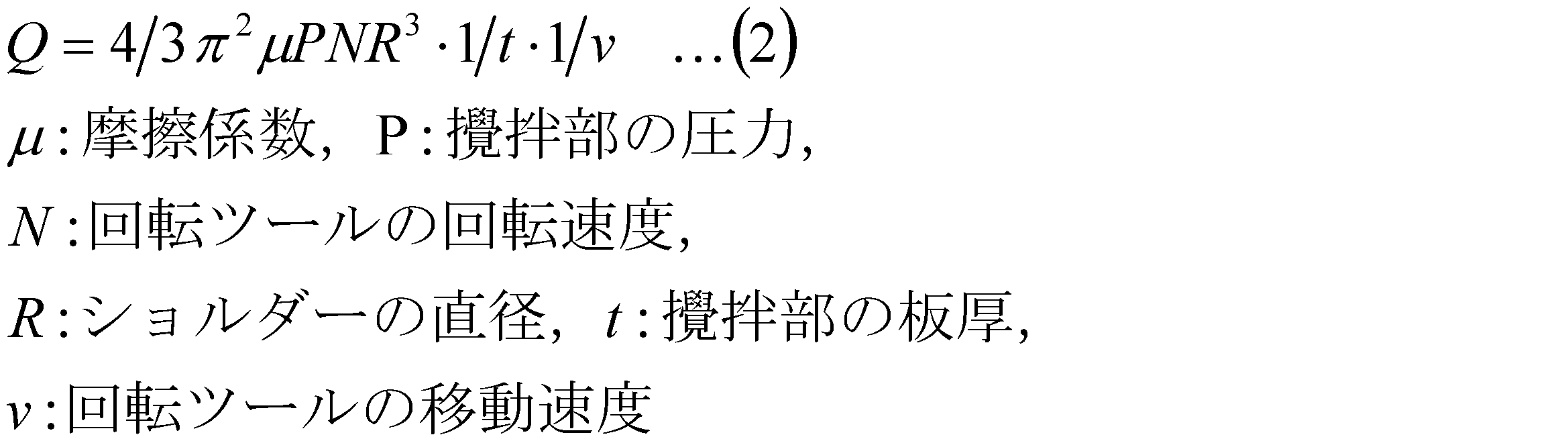
- the amount of heat input Q to the stirring unit 20 during the friction stirring process can be obtained by the following equation (2).
- the amount of M f point that is a temperature at which the entire structure of the base materials 1a and 1b becomes martensite is estimated to be lower than the temperature at which the steel material is used.
- austenite remains in the structure of the stirring unit 20 of the base materials 1a and 1b (S102).
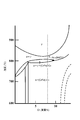
- FIG. 6 when strain is introduced into the stirring portions 20 of the base materials 1a and 1b, the M s point, which is the temperature at which martensite appears, decreases.
- the M f point (not shown), which is a temperature lower than the M s point and at which the entire structure of the base materials 1a and 1b becomes martensite, also decreases.
- both the M f point and the M s point are lowered to a temperature lower than room temperature (20 ° C.).
- room temperature 20 ° C.
- it is possible to leave austenite at the temperature at which the steel material is used by lowering the Mf point below the temperature at which the steel material is used.
- the M s point can be lowered below the temperature at which the steel material is used.
- the strain is introduced into the stirring unit 20 of the base materials 1a and 1b by rotating the probe 102 at the tip of the rotary tool 100 while contacting the stirring unit 20 of the base materials 1a and 1b. It can be performed in one process simultaneously with heating to the AC 1 point or higher.
- the amount of strain introduced using the friction stir welding technique can be obtained by the following equation (4).
- ⁇ is a strain (in the following equation, strain rate, which is the amount of strain introduced per unit time obtained by differentiating ⁇ with respect to time), and R m is 1 / of the rotational speed of the rotary tool 100.
- r e is the effective (average) radius of the stirring unit 20
- L e is the effective (average) depth of the stirring unit 20.
- the stirring unit 20 of the base materials 1a and 1b is cooled to a temperature at which the steel material is used (S103).
- S103 a temperature at which the steel material is used
- the stirrer 20 of the base materials 1a and 1b is completed within the region where pearlite is generated in the stirrer 20 of the base materials 1a and 1b on the CCT diagram as shown in FIG. 6, the stirrer of the base materials 1a and 1b is completed.
- the structure of the part 20 becomes pearlite and no austenite remains.
- the cooling curves of the stirring parts 20 of the base materials 1 a and 1 b are shown in the region where the martensite of the stirring parts 20 of the base materials 1 a and 1 b is generated on the CCT diagram. Due to the cooling rate estimated that the extrapolated lines intersect, the stirring portions 20 of the base materials 1a and 1b are cooled to a temperature that is at least higher than the Mf point, for example, higher than the Ms point (S103). Thereby, austenite remains in the stirring part 20 of the base materials 1a and 1b after cooling.
- the cooling of the stirrer 20 of the base materials 1a and 1b is performed in a state where the probe 102 at the tip of the rotary tool 100 is in contact with the stirrer 20 of the base materials 1a and 1b and rotated.
- the cooling speed can be increased by increasing the rotational speed or moving speed (joining speed) of the rotating tool 100, and the cooling speed can be decreased by decreasing the rotating speed or moving speed (joining speed) of the rotating tool 100.
- a sample of the stirring unit 20 of the base materials 1a and 1b is collected, and the sample structure is inspected (S104).
- the specimen can be inspected by, for example, EBSD (Electron Back-Scatter Diffraction) or XRD (X-ray Diffraction).
- EBSD Electro Back-Scatter Diffraction
- XRD X-ray Diffraction
- austenite remains in the structure of the examined specimen (S105)
- the rotational tool 100 which is the condition of the strain amount introduced in S102 and the cooling rate in S103 is used.
- the diameter of the shoulder 101, the diameter of the probe 102, the length of the probe 102, the rotational speed and the moving speed are maintained (S106).
- the amount of strain can be increased by increasing the number of rotations of the rotary tool 100, increasing the diameter of the shoulder 101, and increasing the diameter of the probe 102.
- the amount of strain can also be increased by lowering the temperature of the stirring unit 20 in the friction stirring process.
- the M s point decreases as the amount of C added increases, and therefore the M s point can be further decreased by increasing the amount of C in the additive 10. It becomes possible.
- the effect of lowering the M s point and the M f point has the greatest influence on the amount of addition of C. Therefore, by controlling the amount of C in the additive 10, the reduction of the M s point and the M f point can be reduced. The degree can be controlled.
- Mn in additive 10 Ni by increasing either the amount of Cr and Mo, it is possible to increase the degree of reduction of the M s point and M f point.
- the increase in the cooling rate is realized by increasing the rotational speed or moving speed (joining speed) of the rotary tool 100. Or it implement
- the region where pearlite or ferrite is generated is an element having an atomic radius larger than that of Fe such as Mo, W, V, and Ta in the additive 10 to the base materials 1a and 1b. It decreases as the amount of elements that inhibit diffusion transformation increases.
- FIG. 6 when strain is introduced into the stirring unit 20, a region where pearlite or ferrite is generated is increased accordingly, but larger than Fe such as Mo, W, V, and Ta. When atoms are added, it is considered that the diffusion transformation is inhibited and the action of increasing the region where pearlite or ferrite is generated is suppressed.
- ferrite or pearlite is generated even at the same cooling rate by increasing the amount of an element having a larger atomic radius than Fe that inhibits the diffusion transformation such as Mo, W, V, and Ta in the additive 10.
- the cooling can be terminated not in the region where the austenite is left but in the region where the austenite remains.
- the following steel material is manufactured under the conditions controlled as described above (S109). Even if austenite remains in S105, the process of S107 is performed when martensite is generated, and the process of S108 is performed when ferrite or pearlite is generated. Thus, in the production of the next steel material, a steel material in which more austenite remains can be produced.
- the base materials 1a and 1b of the steel material are heated to the AC1 point or higher, which is the temperature at which austenite appears (S101). Thereby, austenite can appear in the base materials 1a and 1b.
- An amount of strain estimated to decrease the Mf point, which is the temperature at which the entire structure of the base materials 1a and 1b becomes martensite, falls below room temperature is introduced into the base material (S102). For this reason, it is possible to prevent the entire structure of the steel material from becoming martensite when the steel material is cooled to room temperature.
- CCT diagram Continuous Cooling Transformation diagram
- the strained austenite transforms into hard martensite, and the strength of the strained portion is improved. As a result, deformation of this portion is suppressed, and a TRIP effect is generated in which the transformation propagates to the untransformed austenite portion having a relatively low strength. For this reason, the steel material which has high ductility while having high intensity
- the steel material is subjected to a treatment globally or locally to increase the strength. It is possible to make a steel material having strength and high ductility. For example, in a specific part of a structural member of an automobile, it is necessary to protect the occupant by absorbing the impact with high ductility while maintaining the shape of the vehicle body with high strength against the impact at the time of collision. However, according to the present embodiment, it is possible to add a local treatment to a specific part of the base material of the steel material so that only the specific part has high strength and high ductility.
- tissue of the base materials 1a and 1b is further included (S104).
- S105 When it is found that no austenite remains in the structure of the base material and martensite is generated (S105), it is estimated that the Mf point is not sufficiently lowered with respect to room temperature. Therefore, when the steel material is manufactured next time, the amount of strain introduced into the base materials 1a and 1b in S102 and austenite stabilization such as C, Mn, Ni, Cr and Mo to the base materials 1a and 1b are increased. At least one of the addition amounts of the elements is increased (S107). Thereby, the Mf point can be sufficiently lowered with respect to room temperature, and austenite can be left.
- the base materials 1a and 1b are heated and applied to the base materials 1a and 1b.
- the base material 100 is cooled by introducing strain and moving the tip of the rotary tool 100 while rotating the rotary tool 100 while the tips of the rotary tool 100 are in contact with the base materials 1a and 1b.
- heating, strain introduction, and cooling can be performed in one process.
- the friction stir welding technique it becomes easy to locally heat the base materials 1a and 1b and to locally introduce strain into the base materials 1a and 1b.
- the cooling rate can be easily controlled by adjusting the moving speed of the tip of the rotary tool 100 and the rotational speed of the rotary tool 100.
- this invention is not limited to the said embodiment, A various deformation
- the base materials 1a and 1b are moved by moving the tip of the rotary tool 100 while the rotary tool 100 is rotated while the tip of the rotary tool 100 is in contact with the base materials 1a and 1b.
- the aspect which joined steel and produces steel materials in the stirring part 20 by joining was mainly demonstrated.
- the distal end portion of the rotary tool 100 is rotated at one or more sites in a state where the rotary tool 100 is rotated while the distal end portion of the rotary tool 100 is in contact with the base materials 1a and 1b.
- a steel material may be generated in the stirring unit 20 by a spot-type friction stir welding technique to be stopped.
- the base materials 1a and 1b can be cooled by separating the tip of the rotary tool 100 from the base materials 1a and 1b.
- the cooling rate can be controlled by adjusting the pulling speed, rotating speed, and the like of the rotary tool 100.
- the plate-like base materials 1a and 1b are overlapped, and the powdery or granular additive 10 is filled between them, or the plate-like or sheet-like additive 10 is placed and stirred. Even if the friction stir processing is performed in a manner similar to the superposition joining in which the stirring unit 20 is stirred by rotating the rotating tool 100 in contact with the base material 1a and moving it on the base material 1a. good. Also in this case, a spot-type friction stirring process without the movement of the rotary tool 100 can be performed.
- the rotary tool 100 is brought into contact with the base 1a.
- the structure of the stirring unit 20 may be modified by causing the stirring unit 20 to generate a steel material by stirring the stirring unit 20 by rotating and rotating the base material 1a. Also in this case, a spot-type friction stirring process without the movement of the rotary tool 100 can be performed. In the above-described various friction stir welding and friction stir processing, the arrangement of the additive 10 can be omitted if unnecessary.
- the embodiment of the present invention is not limited to this, and the friction stir processing is performed by performing heating, introduction of strain and cooling to the base material of the steel material so as to meet the conditions specified in the embodiment of the present invention. It is possible to manufacture a steel material having high strength and high ductility.
- the heating of the base material of the steel material can also be performed by a predetermined heat source or the like.
- the introduction of strain into the base material of the steel material can also be performed by processes such as rolling and forging.
- the base material of the steel material can be cooled by a predetermined cooling means.
- the rotational speed was 100 to 400 rpm, and the joining speed was constant at 100 mm / min.
- the steel material 1 is at 750 ° C. or higher, the steel material 1 is easily softened rapidly, so that the load was reduced as much as possible.
- argon gas was used as a shielding gas at a flow rate of 30 l / min to prevent oxidation of the rotating tool and the stirring unit.
- a water-cooled cooling holder was installed to cool the rotating tool and the joining device.
- the stirring unit was inspected. As shown in the phase maps of FIGS. 11 (a) to 11 (d), the structure of the base material of the steel material 1 is ferrite and tempered martensite. It can be confirmed that the amount of retained austenite shown in gray in the three colors of white increases.
- the joint was inspected by EBSD.
- the base material of the steel material 2 shown in FIG. 16 and the joint portion of the steel material 2 shown in FIG. 17 under the condition of rotational speed 400 rpm ⁇ joining speed 100 mm / min there is little residual austenite shown in gray in the figure. I understand.
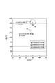
- Tensile tests were performed on the joints obtained from the base metal and each joining speed. As shown in FIG. 19, it can be seen that the joint having a large amount of retained austenite and a joining speed of 400 mm / min is improved in both strength and ductility as compared with the base material.
Landscapes
- Chemical & Material Sciences (AREA)
- Engineering & Computer Science (AREA)
- Mechanical Engineering (AREA)
- Materials Engineering (AREA)
- Thermal Sciences (AREA)
- Crystallography & Structural Chemistry (AREA)
- Physics & Mathematics (AREA)
- Metallurgy (AREA)
- Organic Chemistry (AREA)
- Pressure Welding/Diffusion-Bonding (AREA)
- Heat Treatment Of Steel (AREA)
- Aiming, Guidance, Guns With A Light Source, Armor, Camouflage, And Targets (AREA)
- Adornments (AREA)
Abstract
Description




以下、本実施形態の実験例について説明する。図10に示す化学的組成を有する鉄鋼材1について、摩擦攪拌接合の技術を利用して接合部に鉄鋼材を生成した。回転ツールとしては、WCの超硬合金ツールを使用した。ネジを有しない円柱状のプローブ及び10°の凹み傾斜を有するショルダーを特徴とする単純形状のツールを用いた。長さ200mm×幅50mm×厚さ1.5mmの鉄鋼材1の平板の端部同士を突き合わせ、摩擦攪拌接合により接合した。接合条件は、ショルダーの直径=12mm、プローブの直径=4mm、プローブの長さ=1.3mm、回転ツールの傾き=3°とした。回転速度は100~400rpmとし、接合速度は100mm/minで一定とした。鉄鋼材1は750℃以上にあると急激に軟化しやすくなるため荷重を出来るだけ減少させて接合を行った。接合時は回転ツールおよび攪拌部の酸化防止のためにシールドガスとしてアルゴンガスを30l/minの流量で使用した。回転ツール及び接合装置の冷却のために水冷のクーリングホルダーを装着した。
図15に示す化学的組成を有する鉄鋼材2及び鉄鋼材3について、摩擦攪拌接合の技術を利用して接合部に鉄鋼材を生成した。接合条件は、ショルダーの直径=12mm、プローブの直径=4mm、プローブの長さ=1.4mmとした。接合条件としては、回転ツールの回転速度=200~400rpm、接合速度=100,400mm/min、回転ツールから母材への接合荷重=1500~3300kg、鉄鋼材2及び鉄鋼材3の板厚=1.6mmとした。鉄鋼材2については、回転速度400rpmで一定とし、接合速度を100及び400mm/minに変化させた。鉄鋼材3については、接合速度を400mm/minで一定とし、回転速度を200,300及び400rpmに変化させた。
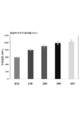
図24に示す化学的組成を有する鉄鋼材4について、摩擦攪拌接合の技術を利用して接合部に鉄鋼材を生成した。板厚=2mm、回転ツールの回転速度=100~400rpmとし、回転ツールの移動速度は100mm/minで一定とした。回転ツールは、超硬合金製であり、ショルダーの直径=12mm、プローブの直径=4mm、プローブの長さ=1.8mmとした。得られた接合部をXRDにより検査した。図25に示すように、回転速度が増加すると残留オーステナイト(γ)のピークが大きくなっていることが判る。
10 添加材
20 攪拌部
100 回転ツール
101 ショルダー
102 プローブ
Claims (3)
- 鉄鋼材の母材をオーステナイトが出現する温度であるAC1点以上に加熱する加熱工程と、
前記母材の組織全面がマルテンサイトとなる温度であるMf点が前記鉄鋼材が使用される温度未満に低下すると推定される量のひずみを前記母材に導入するひずみ導入工程と、
連続冷却変態線図(CCT線図)上の前記母材にマルテンサイトが生成される領域に冷却曲線を外挿した線が交わると推定される冷却速度により、前記加熱工程及び前記ひずみ導入工程が施された前記母材を前記Mf点より高い温度に冷却する冷却工程と、を含む鉄鋼材の製造方法。 - 前記冷却工程が施された前記母材の組織を検査する検査工程をさらに含み、
前記検査工程において前記母材の組織にオーステナイトが残留しておらず、マルテンサイトが生成していることが判明したときは、次に前記鉄鋼材を製造する際に、前記ひずみ導入工程における前記母材に導入するひずみの量の増加、及び前記母材へのオーステナイト安定化元素の添加量の増加の少なくともいずれかを行い、
前記検査工程において前記母材の組織にオーステナイトが残留しておらず、フェライト及びパーライトのいずれかが生成していることが判明したときは、次に前記鉄鋼材を製造する際に、前記冷却工程における前記冷却速度の増加及び前記母材への拡散変態を抑制する元素の添加量の増加の少なくともいずれかを行う、請求項1に記載の鉄鋼材の製造方法。 - 前記加熱工程及び前記ひずみ導入工程では、前記母材に棒状の回転ツールの先端部を当接させながら前記回転ツールを回転させることにより、前記母材の加熱及び前記母材へのひずみの導入を行い、
前記冷却工程では、前記母材に前記回転ツールの前記先端部を当接させながら前記回転ツールを回転させた状態で前記回転ツールの前記先端部を移動させること、及び前記回転ツールの前記先端部を前記母材から離すことの少なくともいずれかにより、前記母材の冷却を行う、請求項1又は2に記載の鉄鋼材の製造方法。
Priority Applications (4)
| Application Number | Priority Date | Filing Date | Title |
|---|---|---|---|
| CN201380014331.4A CN104204233B (zh) | 2012-03-14 | 2013-03-12 | 钢铁材料的制造方法 |
| IN1789MUN2014 IN2014MN01789A (ja) | 2012-03-14 | 2013-03-12 | |
| KR1020147027871A KR102095607B1 (ko) | 2012-03-14 | 2013-03-12 | 철강재의 제조 방법 |
| US14/384,876 US9617613B2 (en) | 2012-03-14 | 2013-03-12 | Method for manufacturing ferrous material |
Applications Claiming Priority (2)
| Application Number | Priority Date | Filing Date | Title |
|---|---|---|---|
| JP2012-057986 | 2012-03-14 | ||
| JP2012057986A JP5900922B2 (ja) | 2012-03-14 | 2012-03-14 | 鉄鋼材の製造方法 |
Publications (1)
| Publication Number | Publication Date |
|---|---|
| WO2013137249A1 true WO2013137249A1 (ja) | 2013-09-19 |
Family
ID=49161155
Family Applications (1)
| Application Number | Title | Priority Date | Filing Date |
|---|---|---|---|
| PCT/JP2013/056800 Ceased WO2013137249A1 (ja) | 2012-03-14 | 2013-03-12 | 鉄鋼材の製造方法 |
Country Status (6)
| Country | Link |
|---|---|
| US (1) | US9617613B2 (ja) |
| JP (1) | JP5900922B2 (ja) |
| KR (1) | KR102095607B1 (ja) |
| CN (1) | CN104204233B (ja) |
| IN (1) | IN2014MN01789A (ja) |
| WO (1) | WO2013137249A1 (ja) |
Cited By (1)
| Publication number | Priority date | Publication date | Assignee | Title |
|---|---|---|---|---|
| JP2018016866A (ja) * | 2016-07-29 | 2018-02-01 | 国立大学法人大阪大学 | 摩擦攪拌接合用鋼及び摩擦攪拌接合方法 |
Families Citing this family (9)
| Publication number | Priority date | Publication date | Assignee | Title |
|---|---|---|---|---|
| US11135674B2 (en) | 2016-06-27 | 2021-10-05 | Kawasaki Jukogyo Kabushiki Kaisha | Friction stir spot welding method and friction stir spot welding device |
| CN112041111B (zh) * | 2018-07-19 | 2022-03-08 | 日本轻金属株式会社 | 液冷套的制造方法 |
| JP2020075255A (ja) * | 2018-11-05 | 2020-05-21 | 日本軽金属株式会社 | 液冷ジャケットの製造方法及び摩擦攪拌接合方法 |
| WO2021025155A1 (ja) * | 2019-08-08 | 2021-02-11 | 日本軽金属株式会社 | 自動接合システム |
| JP6698927B1 (ja) * | 2019-08-22 | 2020-05-27 | 株式会社フルヤ金属 | 金属系筒材の製造方法及びそれに用いられる裏当て治具 |
| KR102147609B1 (ko) | 2019-12-12 | 2020-08-24 | 박성룡 | 프레스 금형용 철강 제조 공정을 위한 제어 방법 및 장치 |
| JP7347235B2 (ja) * | 2020-01-24 | 2023-09-20 | 日本軽金属株式会社 | 液冷ジャケットの製造方法及び摩擦攪拌接合方法 |
| JP7347234B2 (ja) * | 2020-01-24 | 2023-09-20 | 日本軽金属株式会社 | 液冷ジャケットの製造方法及び摩擦攪拌接合方法 |
| CN113798656B (zh) * | 2021-09-07 | 2023-07-25 | 西安建筑科技大学 | 一种高强度钢差动稳奥搅拌摩擦焊接方法和焊接接头 |
Citations (3)
| Publication number | Priority date | Publication date | Assignee | Title |
|---|---|---|---|---|
| JP2008073694A (ja) * | 2006-09-19 | 2008-04-03 | Mazda Motor Corp | 摩擦接合方法 |
| WO2010059201A2 (en) * | 2008-11-18 | 2010-05-27 | Exxonmobil Research And Engineering Company | High strength and toughness steel structures by friction stir welding |
| JP2012040584A (ja) * | 2010-08-17 | 2012-03-01 | Osaka Univ | 鉄系材料の接合方法 |
Family Cites Families (22)
| Publication number | Priority date | Publication date | Assignee | Title |
|---|---|---|---|---|
| DE1458990B2 (de) * | 1962-04-11 | 1971-07-01 | Ford Werke AG, 5000KoIn | Verfahren zum verbessern der mechanischen eigenschaften von haertbarem stahl |
| US4609410A (en) * | 1980-12-04 | 1986-09-02 | United States Steel Corporation | Method for producing high-strength deep-drawable dual-phase steel sheets |
| CA2004548C (en) * | 1988-12-05 | 1996-12-31 | Kenji Aihara | Metallic material having ultra-fine grain structure and method for its manufacture |
| JP3496289B2 (ja) * | 1994-09-30 | 2004-02-09 | 大同特殊鋼株式会社 | マルテンサイト系析出硬化型ステンレス鋼高強度部材の製造方法 |
| US6319338B1 (en) * | 1996-11-28 | 2001-11-20 | Nippon Steel Corporation | High-strength steel plate having high dynamic deformation resistance and method of manufacturing the same |
| JP2002273579A (ja) * | 2001-03-15 | 2002-09-25 | Hitachi Ltd | 鉄基材料の接合方法およびその構造物 |
| DE60228395D1 (de) * | 2001-12-26 | 2008-10-02 | Jfe Steel Corp | Strukturbauelement eines Fahrzeuges aus Martensitischem Rostfreistahlblech |
| AU2005227556B2 (en) * | 2004-03-31 | 2008-02-14 | Jfe Steel Corporation | High-rigidity high-strength thin steel sheet and method for producing same |
| BRPI0608954B1 (pt) * | 2005-03-30 | 2017-06-20 | Nippon Steel & Sumitomo Metal Corporation | Method for manufacturing a martensitic stainless steel tube |
| US8968495B2 (en) * | 2007-03-23 | 2015-03-03 | Dayton Progress Corporation | Methods of thermo-mechanically processing tool steel and tools made from thermo-mechanically processed tool steels |
| US8920583B2 (en) * | 2007-07-23 | 2014-12-30 | Nippon Steel & Sumitomo Metal Corporation | Steel pipe excellent in deformation characteristics and method of producing the same |
| GB0719457D0 (en) * | 2007-10-04 | 2007-11-14 | Skf Ab | Heat-treatment process for a steel |
| CN101323054B (zh) * | 2007-11-09 | 2010-09-01 | 罗键 | 导电-搅拌摩擦复合热源焊接方法及设备 |
| WO2010019735A2 (en) * | 2008-08-14 | 2010-02-18 | Smith International, Inc. | Methods of treating hardbanded joints of pipe using friction stir processing |
| US7874471B2 (en) * | 2008-12-23 | 2011-01-25 | Exxonmobil Research And Engineering Company | Butt weld and method of making using fusion and friction stir welding |
| CN101559534B (zh) * | 2009-05-18 | 2012-07-25 | 北京科技大学 | 可改善焊缝性能的多足式搅拌摩擦焊焊接方法 |
| JP4737319B2 (ja) * | 2009-06-17 | 2011-07-27 | Jfeスチール株式会社 | 加工性および耐疲労特性に優れた高強度合金化溶融亜鉛めっき鋼板およびその製造方法 |
| JP5287770B2 (ja) * | 2010-03-09 | 2013-09-11 | Jfeスチール株式会社 | 高強度鋼板およびその製造方法 |
| JP5333298B2 (ja) * | 2010-03-09 | 2013-11-06 | Jfeスチール株式会社 | 高強度鋼板の製造方法 |
| US9745639B2 (en) * | 2011-06-13 | 2017-08-29 | Kobe Steel, Ltd. | High-strength steel sheet excellent in workability and cold brittleness resistance, and manufacturing method thereof |
| ES2711911T3 (es) * | 2012-02-22 | 2019-05-08 | Nippon Steel & Sumitomo Metal Corp | Chapa de acero laminado en frío y método de fabricación de ésta |
| US20130240096A1 (en) * | 2012-03-16 | 2013-09-19 | Gm Global Technology Operations Llc. | Phase change graded sma actuators |
-
2012
- 2012-03-14 JP JP2012057986A patent/JP5900922B2/ja not_active Expired - Fee Related
-
2013
- 2013-03-12 US US14/384,876 patent/US9617613B2/en not_active Expired - Fee Related
- 2013-03-12 CN CN201380014331.4A patent/CN104204233B/zh not_active Expired - Fee Related
- 2013-03-12 KR KR1020147027871A patent/KR102095607B1/ko not_active Expired - Fee Related
- 2013-03-12 IN IN1789MUN2014 patent/IN2014MN01789A/en unknown
- 2013-03-12 WO PCT/JP2013/056800 patent/WO2013137249A1/ja not_active Ceased
Patent Citations (3)
| Publication number | Priority date | Publication date | Assignee | Title |
|---|---|---|---|---|
| JP2008073694A (ja) * | 2006-09-19 | 2008-04-03 | Mazda Motor Corp | 摩擦接合方法 |
| WO2010059201A2 (en) * | 2008-11-18 | 2010-05-27 | Exxonmobil Research And Engineering Company | High strength and toughness steel structures by friction stir welding |
| JP2012040584A (ja) * | 2010-08-17 | 2012-03-01 | Osaka Univ | 鉄系材料の接合方法 |
Cited By (1)
| Publication number | Priority date | Publication date | Assignee | Title |
|---|---|---|---|---|
| JP2018016866A (ja) * | 2016-07-29 | 2018-02-01 | 国立大学法人大阪大学 | 摩擦攪拌接合用鋼及び摩擦攪拌接合方法 |
Also Published As
| Publication number | Publication date |
|---|---|
| KR102095607B1 (ko) | 2020-03-31 |
| US20150007912A1 (en) | 2015-01-08 |
| US9617613B2 (en) | 2017-04-11 |
| CN104204233A (zh) | 2014-12-10 |
| JP5900922B2 (ja) | 2016-04-06 |
| IN2014MN01789A (ja) | 2015-07-03 |
| CN104204233B (zh) | 2016-07-20 |
| KR20140132396A (ko) | 2014-11-17 |
| JP2013189692A (ja) | 2013-09-26 |
Similar Documents
| Publication | Publication Date | Title |
|---|---|---|
| JP5900922B2 (ja) | 鉄鋼材の製造方法 | |
| Adomako et al. | Laser dissimilar welding of CoCrFeMnNi-high entropy alloy and duplex stainless steel | |
| Sabzi et al. | An experimental investigation on the effect of gas tungsten arc welding current modes upon the microstructure, mechanical, and fractography properties of welded joints of two grades of AISI 316L and AISI310S alloy metal sheets | |
| Sabzi et al. | Post weld heat treatment of hypereutectoid hadfield steel: characterization and control of microstructure, phase equilibrium, mechanical properties and fracture mode of welding joint | |
| Kumar et al. | Microstructure and mechanical properties of friction stir welded AISI 316L austenitic stainless steel joints | |
| Lathabai et al. | Comparison of keyhole and conventional gas tungsten arc welds in commercially pure titanium | |
| Jia et al. | Microstructure and mechanical properties of laser welded dissimilar joints between QP and boron alloyed martensitic steels | |
| Vidyarthy et al. | Influence of M-TIG and A-TIG welding process on microstructure and mechanical behavior of 409 ferritic stainless steel | |
| Mahmoudiniya et al. | Friction stir welding of advanced high strength dual phase steel: Microstructure, mechanical properties and fracture behavior | |
| Khodir et al. | Microstructures and mechanical properties evolution during friction stir welding of SK4 high carbon steel alloy | |
| Tuncel et al. | Effect of heat input on HAZ softening in fiber laser welding of 22MnB5 steel | |
| Karami et al. | Engineering tensile properties by controlling welding parameters and microstructure in a mild steel processed by friction stir welding | |
| Ragab et al. | Microstructure evolution during friction stir welding of 1Cr11Ni2W2MoV martensitic stainless steel at different tool rotation rates | |
| Jun et al. | Microstructure and mechanical properties of adjustable-ring-mode laser welded and hot-stamped Al–Si coated boron steel joints | |
| Wang et al. | Effect of welding speed on microstructure and mechanical properties of laser-welded transformation induced plasticity (TRIP) steels: T. Wang et al. | |
| Sommer et al. | Laser-induction welding of nodular grey cast iron using oscillating beam guidance-microstructural and mechanical characterization | |
| Ramachandran et al. | Effect of paint baking on the fusion boundary softening and fracture behavior of Q&P 980 steel resistance spot welds | |
| Gain et al. | Exploring friction stir welding for joining 316L steel pipes for industrial applications: Mechanical and metallurgical characterization of the joint and analysis of failure | |
| Kong et al. | Design of ultra-strong but ductile iron-based alloys with low supersaturations | |
| Rajeshkannan et al. | Role of arc rotational speed and post-weld heat treatment on the microstructure and mechanical characteristics of 15CDV6 HSLA steel weld joints made by spin arc GMAW | |
| Madeja et al. | Welding of Ti-5Al-5Mo-5 V-1Cr-1Fe parts manufactured in the Electron Beam Melting | |
| Das et al. | Texture and precipitation behavior of friction stir welded Inconel 825 alloy | |
| Cheng et al. | Friction stir welding of ductile iron and low carbon steel | |
| Lv et al. | Microstructures and tensile properties of Fe-30Mn-9Al-0.85 C lightweight steel by friction stir processing and post-aging treatment | |
| Guo et al. | High-performance laser welding of thin Al-Si coated press-hardened steel with dissimilar thicknesses |
Legal Events
| Date | Code | Title | Description |
|---|---|---|---|
| 121 | Ep: the epo has been informed by wipo that ep was designated in this application |
Ref document number: 13761627 Country of ref document: EP Kind code of ref document: A1 |
|
| DPE2 | Request for preliminary examination filed before expiration of 19th month from priority date (pct application filed from 20040101) | ||
| WWE | Wipo information: entry into national phase |
Ref document number: 14384876 Country of ref document: US |
|
| NENP | Non-entry into the national phase |
Ref country code: DE |
|
| ENP | Entry into the national phase |
Ref document number: 20147027871 Country of ref document: KR Kind code of ref document: A |
|
| 122 | Ep: pct application non-entry in european phase |
Ref document number: 13761627 Country of ref document: EP Kind code of ref document: A1 |