WO2013137168A1 - Vehicle wheel disc and manufacturing method therefor - Google Patents
Vehicle wheel disc and manufacturing method therefor Download PDFInfo
- Publication number
- WO2013137168A1 WO2013137168A1 PCT/JP2013/056588 JP2013056588W WO2013137168A1 WO 2013137168 A1 WO2013137168 A1 WO 2013137168A1 JP 2013056588 W JP2013056588 W JP 2013056588W WO 2013137168 A1 WO2013137168 A1 WO 2013137168A1
- Authority
- WO
- WIPO (PCT)
- Prior art keywords
- disk
- disc
- hat
- wheel
- plate thickness
- Prior art date
Links
Images


Classifications
-
- B—PERFORMING OPERATIONS; TRANSPORTING
- B60—VEHICLES IN GENERAL
- B60B—VEHICLE WHEELS; CASTORS; AXLES FOR WHEELS OR CASTORS; INCREASING WHEEL ADHESION
- B60B3/00—Disc wheels, i.e. wheels with load-supporting disc body
- B60B3/002—Disc wheels, i.e. wheels with load-supporting disc body characterised by the shape of the disc
- B60B3/004—Disc wheels, i.e. wheels with load-supporting disc body characterised by the shape of the disc in the hub section
-
- B—PERFORMING OPERATIONS; TRANSPORTING
- B21—MECHANICAL METAL-WORKING WITHOUT ESSENTIALLY REMOVING MATERIAL; PUNCHING METAL
- B21D—WORKING OR PROCESSING OF SHEET METAL OR METAL TUBES, RODS OR PROFILES WITHOUT ESSENTIALLY REMOVING MATERIAL; PUNCHING METAL
- B21D19/00—Flanging or other edge treatment, e.g. of tubes
- B21D19/08—Flanging or other edge treatment, e.g. of tubes by single or successive action of pressing tools, e.g. vice jaws
-
- B—PERFORMING OPERATIONS; TRANSPORTING
- B21—MECHANICAL METAL-WORKING WITHOUT ESSENTIALLY REMOVING MATERIAL; PUNCHING METAL
- B21D—WORKING OR PROCESSING OF SHEET METAL OR METAL TUBES, RODS OR PROFILES WITHOUT ESSENTIALLY REMOVING MATERIAL; PUNCHING METAL
- B21D22/00—Shaping without cutting, by stamping, spinning, or deep-drawing
- B21D22/02—Stamping using rigid devices or tools
-
- B—PERFORMING OPERATIONS; TRANSPORTING
- B21—MECHANICAL METAL-WORKING WITHOUT ESSENTIALLY REMOVING MATERIAL; PUNCHING METAL
- B21D—WORKING OR PROCESSING OF SHEET METAL OR METAL TUBES, RODS OR PROFILES WITHOUT ESSENTIALLY REMOVING MATERIAL; PUNCHING METAL
- B21D35/00—Combined processes according to or processes combined with methods covered by groups B21D1/00 - B21D31/00
- B21D35/002—Processes combined with methods covered by groups B21D1/00 - B21D31/00
- B21D35/005—Processes combined with methods covered by groups B21D1/00 - B21D31/00 characterized by the material of the blank or the workpiece
- B21D35/006—Blanks having varying thickness, e.g. tailored blanks
-
- B—PERFORMING OPERATIONS; TRANSPORTING
- B21—MECHANICAL METAL-WORKING WITHOUT ESSENTIALLY REMOVING MATERIAL; PUNCHING METAL
- B21D—WORKING OR PROCESSING OF SHEET METAL OR METAL TUBES, RODS OR PROFILES WITHOUT ESSENTIALLY REMOVING MATERIAL; PUNCHING METAL
- B21D53/00—Making other particular articles
- B21D53/26—Making other particular articles wheels or the like
- B21D53/30—Making other particular articles wheels or the like wheel rims
-
- B—PERFORMING OPERATIONS; TRANSPORTING
- B60—VEHICLES IN GENERAL
- B60B—VEHICLE WHEELS; CASTORS; AXLES FOR WHEELS OR CASTORS; INCREASING WHEEL ADHESION
- B60B3/00—Disc wheels, i.e. wheels with load-supporting disc body
- B60B3/002—Disc wheels, i.e. wheels with load-supporting disc body characterised by the shape of the disc
- B60B3/005—Disc wheels, i.e. wheels with load-supporting disc body characterised by the shape of the disc in the section adjacent to rim
-
- B—PERFORMING OPERATIONS; TRANSPORTING
- B60—VEHICLES IN GENERAL
- B60B—VEHICLE WHEELS; CASTORS; AXLES FOR WHEELS OR CASTORS; INCREASING WHEEL ADHESION
- B60B3/00—Disc wheels, i.e. wheels with load-supporting disc body
- B60B3/02—Disc wheels, i.e. wheels with load-supporting disc body with a single disc body integral with rim
-
- B—PERFORMING OPERATIONS; TRANSPORTING
- B60—VEHICLES IN GENERAL
- B60B—VEHICLE WHEELS; CASTORS; AXLES FOR WHEELS OR CASTORS; INCREASING WHEEL ADHESION
- B60B3/00—Disc wheels, i.e. wheels with load-supporting disc body
- B60B3/04—Disc wheels, i.e. wheels with load-supporting disc body with a single disc body not integral with rim, i.e. disc body and rim being manufactured independently and then permanently attached to each other in a second step, e.g. by welding
- B60B3/041—Disc wheels, i.e. wheels with load-supporting disc body with a single disc body not integral with rim, i.e. disc body and rim being manufactured independently and then permanently attached to each other in a second step, e.g. by welding characterised by the attachment of rim to wheel disc
- B60B3/044—Disc wheels, i.e. wheels with load-supporting disc body with a single disc body not integral with rim, i.e. disc body and rim being manufactured independently and then permanently attached to each other in a second step, e.g. by welding characterised by the attachment of rim to wheel disc characterised by cross-sectional details of the attachment, e.g. the profile
-
- B—PERFORMING OPERATIONS; TRANSPORTING
- B60—VEHICLES IN GENERAL
- B60B—VEHICLE WHEELS; CASTORS; AXLES FOR WHEELS OR CASTORS; INCREASING WHEEL ADHESION
- B60B3/00—Disc wheels, i.e. wheels with load-supporting disc body
- B60B3/04—Disc wheels, i.e. wheels with load-supporting disc body with a single disc body not integral with rim, i.e. disc body and rim being manufactured independently and then permanently attached to each other in a second step, e.g. by welding
- B60B3/041—Disc wheels, i.e. wheels with load-supporting disc body with a single disc body not integral with rim, i.e. disc body and rim being manufactured independently and then permanently attached to each other in a second step, e.g. by welding characterised by the attachment of rim to wheel disc
- B60B3/045—Disc wheels, i.e. wheels with load-supporting disc body with a single disc body not integral with rim, i.e. disc body and rim being manufactured independently and then permanently attached to each other in a second step, e.g. by welding characterised by the attachment of rim to wheel disc characterised by the attachment portions
-
- B—PERFORMING OPERATIONS; TRANSPORTING
- B60—VEHICLES IN GENERAL
- B60B—VEHICLE WHEELS; CASTORS; AXLES FOR WHEELS OR CASTORS; INCREASING WHEEL ADHESION
- B60B2310/00—Manufacturing methods
-
- B—PERFORMING OPERATIONS; TRANSPORTING
- B60—VEHICLES IN GENERAL
- B60B—VEHICLE WHEELS; CASTORS; AXLES FOR WHEELS OR CASTORS; INCREASING WHEEL ADHESION
- B60B2310/00—Manufacturing methods
- B60B2310/20—Shaping
- B60B2310/212—Shaping by drawing
-
- B—PERFORMING OPERATIONS; TRANSPORTING
- B60—VEHICLES IN GENERAL
- B60B—VEHICLE WHEELS; CASTORS; AXLES FOR WHEELS OR CASTORS; INCREASING WHEEL ADHESION
- B60B2900/00—Purpose of invention
- B60B2900/10—Reduction of
- B60B2900/111—Weight
-
- B—PERFORMING OPERATIONS; TRANSPORTING
- B60—VEHICLES IN GENERAL
- B60B—VEHICLE WHEELS; CASTORS; AXLES FOR WHEELS OR CASTORS; INCREASING WHEEL ADHESION
- B60B2900/00—Purpose of invention
- B60B2900/20—Avoidance of
- B60B2900/212—Damage
-
- B—PERFORMING OPERATIONS; TRANSPORTING
- B60—VEHICLES IN GENERAL
- B60B—VEHICLE WHEELS; CASTORS; AXLES FOR WHEELS OR CASTORS; INCREASING WHEEL ADHESION
- B60B2900/00—Purpose of invention
- B60B2900/30—Increase in
- B60B2900/311—Rigidity or stiffness
-
- B—PERFORMING OPERATIONS; TRANSPORTING
- B60—VEHICLES IN GENERAL
- B60Y—INDEXING SCHEME RELATING TO ASPECTS CROSS-CUTTING VEHICLE TECHNOLOGY
- B60Y2200/00—Type of vehicle
- B60Y2200/10—Road Vehicles
-
- B—PERFORMING OPERATIONS; TRANSPORTING
- B60—VEHICLES IN GENERAL
- B60Y—INDEXING SCHEME RELATING TO ASPECTS CROSS-CUTTING VEHICLE TECHNOLOGY
- B60Y2200/00—Type of vehicle
- B60Y2200/10—Road Vehicles
- B60Y2200/14—Trucks; Load vehicles, Busses
-
- Y—GENERAL TAGGING OF NEW TECHNOLOGICAL DEVELOPMENTS; GENERAL TAGGING OF CROSS-SECTIONAL TECHNOLOGIES SPANNING OVER SEVERAL SECTIONS OF THE IPC; TECHNICAL SUBJECTS COVERED BY FORMER USPC CROSS-REFERENCE ART COLLECTIONS [XRACs] AND DIGESTS
- Y02—TECHNOLOGIES OR APPLICATIONS FOR MITIGATION OR ADAPTATION AGAINST CLIMATE CHANGE
- Y02T—CLIMATE CHANGE MITIGATION TECHNOLOGIES RELATED TO TRANSPORTATION
- Y02T10/00—Road transport of goods or passengers
- Y02T10/80—Technologies aiming to reduce greenhouse gasses emissions common to all road transportation technologies
- Y02T10/86—Optimisation of rolling resistance, e.g. weight reduction
-
- Y—GENERAL TAGGING OF NEW TECHNOLOGICAL DEVELOPMENTS; GENERAL TAGGING OF CROSS-SECTIONAL TECHNOLOGIES SPANNING OVER SEVERAL SECTIONS OF THE IPC; TECHNICAL SUBJECTS COVERED BY FORMER USPC CROSS-REFERENCE ART COLLECTIONS [XRACs] AND DIGESTS
- Y10—TECHNICAL SUBJECTS COVERED BY FORMER USPC
- Y10T—TECHNICAL SUBJECTS COVERED BY FORMER US CLASSIFICATION
- Y10T29/00—Metal working
- Y10T29/49—Method of mechanical manufacture
- Y10T29/49481—Wheel making
- Y10T29/49492—Land wheel
- Y10T29/49496—Disc type wheel
- Y10T29/49504—Disc shaping
Definitions
- the present invention relates to a single attachment type automotive wheel disk having a hat portion and used in a passenger car and the like, and a manufacturing method thereof, and relates to an automotive wheel disk manufactured from a flat disk material and a manufacturing method thereof.
- Patent Documents 1 and 2 disclose a method for manufacturing a wheel disk for automobiles of a single attachment type (a type having a hat portion and used in a passenger car) manufactured from a flat disk material. Patent documents 1 and 2 have disclosed the manufacturing method of the wheel disc for cars which irons a disk flange part and reduces board thickness.
- An object of the present invention is to provide a single mounting type wheel disk for automobiles and a method for manufacturing the same, which can reduce the weight of the disk as compared with the conventional art.
- the present invention for achieving the above object is as follows. (1) Manufactured from flat disk material, A hub attachment portion, a disc flange portion, and a hat portion connecting the hub attachment portion and the disc flange portion; A hat top portion protruding outward in the disk axial direction; a hat inner peripheral portion connecting the hat top portion and the hub mounting portion; and a hat outer peripheral portion connecting the hat top portion and the disc flange portion.
- Have An automotive wheel disc In the outer periphery of the hat, a first plate thickness reduction portion having a plate thickness smaller than the plate thickness of the disk material is provided, Wheel disc for automobile.
- the disk flange portion includes a disk flange portion thick portion at least at a part in the disk circumferential direction at an inner end portion in the disk axial direction of the disk flange portion.
- Automotive wheel disc. (4) A decorative hole is formed on the outer periphery of the hat,
- the first plate thickness reduction portion is provided in any one of (1) to (3), which is provided at a portion of the outer periphery of the hat that is spaced at least on the outer side in the disk radial direction from the decoration hole. Wheel disc for automobile.
- Examples 1 to 4 A method for manufacturing a wheel disk for automobiles, wherein a wheel disk for automobiles is manufactured from a disk material,
- the wheel disc includes a hat top portion, a hat outer peripheral portion, and a hat inner peripheral portion, a disc flange portion, and a first disc portion located outside the disc radial direction from the hat top portion and inside the disc radial direction from the disc flange portion ( D1), a second disk part (D2) at the boundary between the outer periphery of the hat and the disk flange part, a third disk part (D3) at the inner end in the disk axial direction of the disk flange part, A fourth disk portion (D4) located on the inner side in the disk axial direction from the disk portion (D2) and on the outer side in the disk axial direction from the third disk
- a second step of changing one diameter A method for manufacturing a wheel disk for automobiles having (7) [Examples 1 to 3] In the second step, the diameter of both the disk material portion between M2 and M3 and the disk material portion between M1 and M2 is increased, and the method for manufacturing a wheel disk for an automobile according to (6).
- Examples 1 to 4 In the first step, at least a disk material portion between M3 and M4 is formed into a thick portion having a plate thickness larger than that of the adjacent disk material portion or the first plate thickness reduction portion (8) Of manufacturing wheel discs for automobiles. (10) [Examples 1 to 4] The method according to any one of (6) to (9), further comprising a third step of shaping the disc material portion between M2 and M3 into a final disc flange shape after the second step. Of manufacturing wheel discs for automobiles. (11) [Examples 1 to 4] In the third step, at least a part of the disk material portion from M2 to M4 or M2 to M3 is ironed, and the method for manufacturing a wheel disk for an automobile according to (10).
- the wheel disc has a hub attachment
- the disc material includes a hub mounting portion corresponding portion, a hat top corresponding portion, a hat outer peripheral corresponding portion, and a hat inner corresponding portion including a hat inner peripheral corresponding portion, (6) to (11), including a step of preforming the hub attachment portion corresponding portion, the hat inner peripheral portion corresponding portion, and the hat top portion corresponding portion of the disk material before the first step.
- the first plate thickness reduction portion having a plate thickness smaller than the plate thickness of the disc material is provided on the outer periphery of the hat, the weight of the vehicle wheel disc is reduced. Can be effectively and reliably achieved.
- the disc flange portion is provided with the second plate thickness reduction portion having a plate thickness smaller than the plate thickness of the disc material.
- a plate thickness reducing portion is also provided in the flange portion. Therefore, it is possible to reduce the weight of the wheel disc for an automobile as compared with the case where the plate thickness reducing portion is provided only in the disc flange portion.
- the disc flange portion includes the disc flange portion thick portion, the rigidity of the vehicle wheel disc can be improved, and the assembly accuracy with the vehicle wheel rim is also improved. improves.
- the first plate thickness reducing portion is provided at least at the outer peripheral portion of the hat that is separated from the decorative hole on the outer side in the disc radial direction. It is possible to increase the weight reduction rate while securing the strength.
- the second plate thickness reducing portion is provided in the entire area of the disc flange portion in the disc axial direction, and therefore the second plate thickness reducing portion is provided in the disc axial direction. Compared with the case where it is provided only in a part of the disk flange portion, it is possible to reduce the weight of the vehicle wheel disk.
- the method for manufacturing a wheel disk for automobile of (6) above at least a part or all of the disk material portion from M1 to M2 is ironed, and the thickness after the ironing is thinner than the thickness before the ironing. Since it has the 1st process which shape
- the cylindrical part shape-formed by the 1st process can be shape
- both the disk material portion between M2 and M3 and the disk material portion between M1 and M2 are expanded. Therefore, the molding is easier than the case of reducing the diameter of at least one of the disk material portion between M2 and M3 and the disk material portion between M1 and M2.
- the disc material portion from M2 to M4 or M2 to M3 is further ironed, so that not only the outer periphery of the hat but also the disc flange portion
- the disc material portion between M3 and M4 is more than the adjacent disc material portion or the first plate thickness reducing portion. Since it is formed into a thick part having a large plate thickness, it is possible to suppress the occurrence of defects such as cracks in the disk in the second step (particularly during the diameter expansion step).
- the third step of shaping the disc material portion between M2 and M3 to obtain the final disc flange shape after the second step, the third step of shaping the disc material portion between M2 and M3 to obtain the final disc flange shape. Therefore, the disk flange portion can be accurately shaped.
- the disk flange part is accurately formed. In addition to molding, it is possible to reduce the weight of the wheel disk for automobiles.
- the step of preforming the hub attachment portion corresponding portion, the hat inner peripheral portion corresponding portion, and the hat top portion corresponding portion of the disk material before the first step is possible to prevent molding defects such as thinning due to plastic working of the inner peripheral portion of the hat and the hub mounting portion, as compared to the case where the step of preforming is performed before and after the first step.
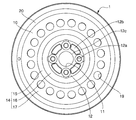
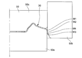
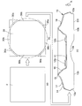
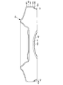
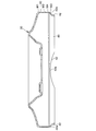
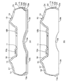
- FIG. 1 It is a front view of the state joined to the rim of the wheel disk for vehicles of the example of the present invention. It is sectional drawing of the state joined to the rim
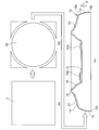
- (A) is a flat plate
- (b) is a circular disk material before the first step
- (c) is a cross section of a wheel disk.
- this figure is also applicable to the second embodiment, the third embodiment, and the fourth embodiment of the present invention.
- FIG. 1 shows the disc material before the first step
- FIG. 1 shows the wheel disc.
- FIG. 1 shows the disc material before the first step
- FIG. 1 shows the wheel disc.
- FIG. 1 shows the disc material before the first step
- FIG. 1 shows the wheel disc.
- FIG. 1 shows the disc material before the first step
- FIG. 1 shows the wheel disc.
- FIG. 1 shows the disc material before the first step
- FIG. 1 shows the wheel disc.
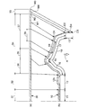
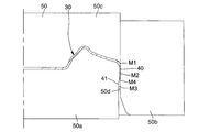
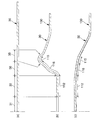
- Embodiment 2 and Embodiment 4 of the present invention It is sectional drawing of the diameter change apparatus just before the 2nd process of the manufacturing method of the wheel disc for motor vehicles of this invention Example 1.
- FIG. However, the left half of the figure is omitted. Note that hatching of the diameter changing device is omitted for clarity of the drawing.
- this figure is applicable also to Example 3 of this invention by changing the board thickness of a board thickness reduction part.
- the present invention can also be applied to the second embodiment.
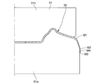
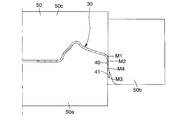
- this figure is also applicable to the second embodiment, the third embodiment, and the fourth embodiment of the present invention. It is sectional drawing of the ironing apparatus after the 1st process of the modification of the manufacturing method of the wheel disk for motor vehicles of Example 1 of this invention. However, the left half of the figure is omitted. Note that hatching of the ironing device is omitted for clarity of the drawing. However, this figure can also be applied to the third embodiment of the present invention by changing the shape of the ironing device and the shape of the cylindrical portion. Moreover, this figure is applicable also to this invention Example 2 and this invention Example 4. FIG. It is sectional drawing of the ironing apparatus after the 1st process of the modification of the manufacturing method of the wheel disk for motor vehicles of Example 1 of this invention.
- FIG. 1 is sectional drawing of the disc raw material after the 1st process of the modification of the manufacturing method of the wheel disc for motor vehicles of Example 1 of this invention.
- this figure can also be applied to the third embodiment of the present invention by changing the shape of the cylindrical portion.
- this figure is applicable also to this invention Example 2 and this invention Example 4.
- FIG. It is the (a) top view and (b) sectional view of the modification of the diameter change apparatus of the 2nd process of the manufacturing method of the wheel disk for vehicles of the example 1 of the present invention. However, (a) the lower half of the plan view is omitted. Note that hatching of the diameter changing device is omitted for clarity of the drawing. Further, the left half of the cross section of the disk material is omitted.
- this figure is also applicable to the second embodiment of the present invention and the third embodiment of the present invention. It is sectional drawing which shows the state before and behind the preforming of the disk raw material of the manufacturing method of the wheel disk for motor vehicles of Example 1 of this invention. However, the left half of the figure is omitted.
- A shows the flat disk-shaped raw material before preforming.
- B shows the disk material after preforming.
- C shows the disk material after preforming into another shape.
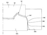
- this figure is also applicable to the second embodiment, the third embodiment, and the fourth embodiment of the present invention. It is sectional drawing of the shaping apparatus after the 3rd process of the manufacturing method of the wheel disk for motor vehicles of this invention Example 2. FIG. However, the left half of the figure is omitted.
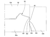
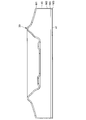
- this figure is also applicable to the second embodiment of the present invention and the third embodiment of the present invention. It is sectional drawing of the diameter change apparatus (reduced diameter) in the state which the 2nd process of the manufacturing method of the wheel disk for motor vehicles of this invention Example 4 was finished. However, the left half of the figure is omitted. Note that hatching of the diameter changing device is omitted for clarity of the drawing. However, this figure is also applicable to the second embodiment of the present invention and the third embodiment of the present invention. It is sectional drawing of the wheel disk after the 3rd process of the modification of the manufacturing method of the wheel disk for motor vehicles of Example 1 of this invention.
- a vehicle wheel disk (hereinafter, also simply referred to as a wheel disk or a disk) 10 is a single attachment type (a type having a hat portion and used in a passenger car). It is.
- the disk 10 is not a double-attached type disk 100 (a type that does not have a hat part and is basically used for a track / bus) as shown in FIG.
- the disk 10 is a disk manufactured from a flat disk material.
- the disk 10 is made of steel, for example. However, the disk 10 may not be made of steel, but may be made of aluminum alloy, titanium alloy, magnesium alloy, or the like.
- the disc 10 is manufactured separately from an annular rim (portion for holding a tire (not shown)) 20 and is joined to the rim 20 by welding, rivet, adhesion or the like to become the wheel 1.
- Rim 20 is manufactured from a plate material.
- the rim 20 includes an inner flange portion 21, an inner bead seat portion 22, an inner sidewall portion 23, a drop portion 24, an outer sidewall portion 25, an outer bead seat portion 26 and an outer flange portion 27.
- the inner flange portion 21, the inner bead seat portion 22, and the inner sidewall portion 23 are arranged in the disc axial direction when the wheel 1 is mounted on the vehicle, rather than the outer sidewall portion 25, the outer bead seat portion 26 and the outer flange portion 27. It is located on the side closer to the inner side of the vehicle (in the wheel axis direction) (center side in the vehicle width direction).
- the disk 10 includes a hub hole 11, a hub mounting part 12, a disk flange part 13, a hat part 14, and a plate thickness reducing part 18.
- the hat portion 14 includes a hat top portion 15, a hat inner peripheral portion 16, and a hat outer peripheral portion 17.
- the disk 10 has a first disk portion (D1) located on the outer side in the disk radial direction from the top 15 of the hat and on the inner side in the disk radial direction from the disk flange part 13, and a second at the boundary between the hat outer peripheral part 17 and the disk flange part 13.
- the entire disc flange portion 13 is a disc flange portion thick portion 13c described later, the second disc portion (D2) and the fourth disc portion (D4) coincide.
- A indicates the inner side in the disk axial direction.
- the hub hole 11 is provided in the center of the disk 10 in the disk radial direction (wheel radial direction).
- the hub attachment portion 12 is provided around the hub hole 11.
- the hub mounting portion 12 has a flat plate shape or a substantially flat plate shape, and is in a plane orthogonal to or substantially orthogonal to the disk axial direction (wheel axial direction).
- a plurality of hub mounting bolt holes 12a are provided in the intermediate portion of the hub mounting portion 12 in the disk radial direction.
- four hub mounting bolt holes 12a are provided at equal intervals on a concentric circle in the disk circumferential direction (wheel circumferential direction).
- the number of hub mounting bolt holes 12a is not limited to four, and may be three or five or more.
- the disk 10 (wheel 1) By inserting hub mounting bolts (both not shown) extending from the vehicle hub into the hub mounting bolt holes 12a and screwing hub nuts (not shown) into the hub mounting bolts, the disk 10 (wheel 1) is fitted to the hub. Fixed. However, the disk 10 (wheel 1) may be fixed to the hub by being screwed into a tap hole formed in the hub mounting portion 12 with a hub bolt. Since the hub mounting portion flat portion 12c, which is a flat portion of the hub mounting portion 12, is not thinned by ironing, the thickness when it is a product is substantially the same as the thickness of the disk material.
- the hub mounting portion 12 may be provided with ribs 12b bulging outwardly in the disk axial direction between the hub mounting bolt holes 12a adjacent to each other in the disk circumferential direction. .
- the ribs 12b are provided to improve the rigidity and durability of the hub mounting portion 12.
- the rib 12b can be provided because the disk 10 is a single mounting type and not a double mounting type. In general, in the double mounting type disc 100 (see FIG. 25), the surface on the inner side of the disc axial direction and the surface on the outer side of the disc axial direction of the hub mounting portion are in close contact with the hub mounting portion of the hub or another wheel. Therefore, the rib 12b is not provided. In the double attachment type disk 100, the rib 12b is difficult to form because the rigidity and strength are increased by making the plate thickness relatively large for the reason of attachment to the hub of the vehicle.
- the disc flange portion 13 is located at the outer end portion (including the vicinity thereof) of the disc 10 in the disc radial direction.
- the disk flange portion 13 has a ring shape continuous in the disk circumferential direction.
- the disk flange portion 13 may have a ring shape partially discontinuous in the disk circumferential direction.
- the disc flange portion 13 extends linearly in the disc axial direction in a disc radial direction cross-sectional view (in a cross-sectional view orthogonal to the disc circumferential direction).
- the inner end of the disk flange portion 13 in the disk axial direction (third disk portion D3) may be located in one plane over the entire circumference in the disk circumferential direction.
- the disk flange portion 13 is a portion that is fitted into the drop portion 24 of the rim 20 and joined (fixed or welded) to the drop portion 24.
- the disk flange portion 13 is viewed from the disk radial direction sectional view until the inner peripheral surface and the outer peripheral surface of the disk 10 both start to incline in the direction intersecting with the disk axial direction of the disk 10 outward from the disk axial inner end D3. It is a disc part.
- the hat portion 14 is provided between the hub attachment portion 12 and the disc flange portion 13 in the disc radial direction, and is a portion connecting the hub attachment portion 12 and the disc flange portion 13 in the disc radial direction.
- the hat portion 14 has a portion located on the outer side in the disc axial direction from the hub attachment portion 12 and the disc flange portion 13. At least the hat top portion 15 of the hat portion 14 is located on the outer side in the disc axial direction from the hub mounting portion 12 and the disc flange portion 13.
- the apex 15a is a point located at the outermost side in the disc axial direction at the hat top 15 (with the disc 10) in an arbitrary disc radial cross section.
- the position of the vertex 15a in the disk axis direction may be constant or different.
- the hat inner peripheral portion 16 is provided between the hub attachment portion 12 and the hat top portion 15 in the disk radial direction, and is a portion connecting the hub attachment portion 12 and the hat top portion 15 in the disk radial direction.
- the inner circumferential portion 16 of the hat has a cross section in the radial direction of the disc, and is entirely or substantially inclined to the outer side in the radial direction of the disc and the outer side in the axial direction of the disc, and smoothly connects the hub attachment portion 12 and the top portion 15 of the hat.
- the hat outer peripheral part 17 is provided between the hat top part 15 and the disk flange part 13 in the disk radial direction, and is a part that connects the hat top part 15 and the disk flange part 13 in the disk radial direction.
- the outer circumferential portion 17 of the hat has a cross section in the disk radial direction, and the whole or substantially the whole is inclined outward in the disk radial direction and inward in the disk axial direction.
- the hat top 15 is a portion protruding outward in the disk axial direction.
- the hat top 15 is a part for securing the rigidity and strength of the disk 10 and protrudes outward in the disk axial direction in an arc shape as shown in FIG.
- the hat top 15 includes a vertex 15a continuously extending in the disk circumferential direction, an inner circumferential curved portion 15b that curves inward in the disk axial direction inside the disk radial direction of the vertex 15a, and a disk axial direction outside the vertex 15a in the disk radial direction.
- An outer peripheral curved portion 15c that curves inward.
- the hat portion 14 extends outward from the hub mounting portion 12 in the radial direction of the disc, and in order from the inner side in the radial direction of the disc, the hat inner circumferential portion 16 extends outward in the axial direction of the disc.
- the hat outer peripheral portion 17 extends inward in the disc axial direction and is connected to the disc flange portion 13. Therefore, the distance between the hub attachment portion 12 and the disc flange portion 13 in the disc axial direction is small, and when the wheel 1 is attached to an automobile, the force is transmitted from the hat portion 14 to the hub attachment portion 12 via the tire and the rim 20. It is difficult to apply a large bending moment.
- the stress state applied to the hat portion 14 of the disk 10 is different from the stress state applied to the hat portion 140 of the double mounting type disk 100.
- a decorative hole 19 is formed in the hat outer peripheral portion 17.
- the decorative hole 19 is provided in the intermediate portion in the disk radial direction of the hat outer peripheral portion 17.
- a plurality of decorative holes 19 are provided at equal intervals in the circumferential direction of the disk.
- the decorative holes 19 may not be provided, may be provided at unequal intervals in the disk circumferential direction, or only one may be provided.
- a portion other than a first plate thickness reducing portion 18a (to be described later) (for example, a portion radially inward of the decorative hole 19) is not greatly deformed by pressing and is thinned by ironing. Therefore, the thickness when it becomes an automobile wheel disc is almost the same as the thickness of the disc material.
- the plate thickness reducing portion 18 is obtained by ironing the flat disk material 30 shown in FIG. 3B or FIG. 11B so that the plate thickness of the disk material 30 before the ironing process (the hub mounting portion of the disk 10).
- the flat portion 12c and the outer peripheral portion 17 of the hat are portions where the plate thickness is smaller than the disk material (such as portions other than the plate thickness reducing portion 18).
- the first disk portion (D1) is a boundary between a portion of the hat outer peripheral portion 17 that is not a portion that is thinned by ironing and that is not a portion. A portion where the plate thickness of the disk material 30 is reduced by shrinkage due to press molding or the like is not the plate thickness reduction portion 18.
- the plate thickness of the plate thickness reducing portion 18 can be 80% or less, or 50% or less of the plate thickness of the disk material 30 before ironing.
- the plate thickness of the thinnest portion of the plate thickness reducing portion 18 can be set to 1 mm, for example.
- the plate thickness of the disk material 30 may be reduced by other methods such as flow forming.
- the plate thickness reducing portion 18 is desirably provided only outside 80% including 80% of the outer diameter of the disc 10 in the disc radial direction, but is not limited to 80% due to the nature of the plate material. This is so that the disk 10 having the plate thickness reducing portion 18 can be formed without cracking.
- the plate thickness reducing portion 18 includes a first plate thickness reducing portion 18 a provided on the hat outer peripheral portion 17.
- the plate thickness reducing portion 18 may further include a second plate thickness reducing portion 18 b provided in the disc flange portion 13.
- the first plate thickness reducing portion 18a and the second plate thickness reducing portion 18b are arranged in the disc axial direction. It may be connected to or may not be continuous.
- the first plate thickness reducing portion 18 a is provided at the outer end portion (including the vicinity thereof) in the disc radial direction of the hat outer peripheral portion 17.
- the first plate thickness reducing portion 18a is provided from the first disk portion D1 to the second disk portion D2.
- the decorative hole 19 is provided only in the disk radial direction intermediate portion of the hat outer peripheral portion 17, the first plate thickness reducing portion 18 a is separated from the outer peripheral portion 17 of the hat outer peripheral portion 17 at least outward in the disk radial direction from the decorative hole 19. It is provided in the part.
- the first plate thickness reducing portion 18 a may include part or all of the peripheral edge portion of the decorative hole 19.
- the plate thickness of the first plate thickness reducing portion 18a may or may not be constant within the first plate thickness reducing portion 18a.
- the plate thickness of at least a part of the first plate thickness reduction portion 18a located at the peripheral portion of the decoration hole 19 may be made thicker than the plate thicknesses of the other first plate thickness reduction portions 18a.
- a part of the plate thickness of the first plate thickness reducing portion 18a may have a portion having a plate thickness substantially the same as the disc material plate thickness.
- the second plate thickness reducing portion 18b is provided in the entire region (entirely) or a part of the disc flange portion 13 in the disc axial direction.
- the second plate thickness reducing portion 18b is provided in the entire region (entirely) or a part from the second disk portion D2 to the third disk portion D3.
- the plate thickness of the second plate thickness reducing portion 18b may or may not be constant within the second plate thickness reducing portion 18b.
- the plate thickness of the second plate thickness reduction portion 18b may be the same as the plate thickness of the first plate thickness reduction portion 18a, or may be greater than the plate thickness of the first plate thickness reduction portion 18a.
- the thickness may be smaller than the thickness of the first thickness reducing portion 18a.
- a part of the plate thickness of the second plate thickness reducing portion 18b may have a portion having a plate thickness substantially the same as the disc material plate thickness.
- the disc flange portion thick portion 13c may be provided at least at the inner end in the disc axial direction of the disc flange portion 13 (for example, from the third disc portion D3 to the fourth disc portion D4).
- the disc flange portion thick portion 13c is a disc portion adjacent to the disc flange portion thick portion 13c in the disc axial direction (for example, the second disc portion D2 to the fourth disc portion D4, the disc flange portion thick portion 13c). Is the portion where the plate thickness is larger than the plate thickness of the first disc portion D1 to the second disc portion D2.
- the disc flange portion thick portion 13c is provided in at least a part of the disc circumferential direction.
- the disc flange portion thick portion 13c may be provided continuously over the entire circumference in the disc circumferential direction, or may be provided intermittently in the disc circumferential direction.
- the disk flange portion thick portion 13c may protrude radially inward as shown in FIG. 24 (a), or may protrude radially outward as shown in FIG. 24 (b). Further, the disk flange portion thick portion 13c may protrude both radially outward and radially inward.
- the rigidity of the disk 10 can be improved. Further, when the disk 10 and the rim 20 are assembled, the plate thickness at the position where the disk flange portion 13 is welded becomes thick, so that welding becomes easy.
- the maximum value of the thickness of the disc flange portion thick portion 13c may be the same as the disc material plate thickness, may be larger than the disc material plate thickness, or may be smaller than the disc material plate thickness. Good.
- the cross-sectional shape between the first disk part D1 and the second disk part D2 may be a straight line as shown in FIG. 24, a large arc shape as a whole, or other shapes. May be.
- FIG. 3 to 19 show a method for manufacturing a wheel disk for automobiles according to Embodiment 1 of the present invention
- FIG. 20 shows a method for manufacturing a wheel disk for automobiles according to Embodiment 2 of the present invention
- 21 shows a method for manufacturing a vehicle wheel disk according to Embodiment 3 of the present invention
- FIGS. 22 and 23 show a method for manufacturing a wheel disk for vehicle according to Embodiment 4 of the present invention.
- the manufacturing method of the wheel disk 10 for automobiles of the embodiment of the present invention is a method for manufacturing the wheel disk 10 for automobiles from the disk material 30 as shown in FIG.
- the disk material 30 includes a hub hole corresponding part 31 corresponding to the hub hole 11, a hub mounting part corresponding part 32 corresponding to the hub mounting part 12, a disk flange part corresponding part 33 corresponding to the disk flange part 13, and a hat part. 14 corresponding to 14, a hat top corresponding portion 35 corresponding to the hat top 15, a hat inner peripheral corresponding portion 36 corresponding to the hat inner peripheral portion 16, and a hat outer periphery corresponding to the hat outer periphery 17.
- a part corresponding part 37 and a decorative hole corresponding part 39 corresponding to the decorative hole 19.
- the disk material 30 also corresponds to a first material part M1 corresponding to the first disk part D1, a second material part M2 corresponding to the second disk part D2, and a third disk part D3.
- a third material part M3 and a fourth material part M4 corresponding to the fourth disk part D4 are provided.
- the disc flange portion corresponding portion 33 is a portion that becomes the disc flange portion 13 when the disc material 30 is manufactured on the disc 10.
- the hat portion corresponding portion 34 is a portion that becomes the hat portion 14 when the disc material 30 is manufactured on the disc 10.
- the hat top corresponding portion 35 is a portion that becomes the hat top 15 when the disc material 30 is manufactured on the disc 10.
- the hat inner periphery corresponding portion 36 is a portion that becomes the hat inner periphery 16 when the disk material 30 is manufactured on the disk 10.
- the hat outer peripheral portion corresponding portion 37 is a portion that becomes the hat outer peripheral portion 17 when the disc material 30 is manufactured on the disc 10.
- the decorative hole corresponding portion 39 is a portion that is punched when the disc material 30 is manufactured into the disc 10 and becomes the decorative hole 19.
- the first material part M1 is a part that becomes the first disk part D1 when the disk material 30 is manufactured on the disk 10.
- the second material part M2 is a part that becomes the second disk part D2 when the disk material 30 is manufactured on the disk 10.
- the third material part M3 is a part that becomes the third disk part D3 when the disk material 30 is manufactured on the disk 10.
- the fourth material part M4 is a part that becomes the fourth disk part D4 when the disk material 30 is manufactured on the disk 10.
- the disk material 30 is a flat plate material in which four corners are dropped from a square (including a substantially square) flat plate 2 by press punching or the like.
- the disc material 30 may be a circular flat plate having no straight part, and has an arc part 30a and a straight part 30b as shown in FIG. 11B. It may be flat.
- the wheel disk 10 manufactured from the disk material 30 does not have the ventilation portion 13a (see FIG. 11C).
- the wheel disk 10 manufactured from the disk material 30 has a ventilation portion 13a as shown in FIG. 11C.
- the arc part 30a becomes the general end part 13b other than the ventilation part 13a
- the linear part 30b becomes the ventilation part 13a.
- the manufacturing method of the wheel disc 10 is as follows: (I) As shown in FIGS. 5 to 7, at least a part or all of the disk material 30 from the first material part M1 to the second material part M2 is ironed, and the thickness after the ironing process is ironed. A first step (squeeze drawing step) for forming a cylindrical portion 40 thinner than the plate thickness before processing; (Ii) After the first step, as shown in FIGS. 8 and 9, the first material portion of the disc material 30 is between the second material portion M2 and the third material portion M3 of the disc material 30. At least one of the second material portion M2 and the third material portion M3 of the disc material 30 and the first material portion M1 of the disc material 30 so as to have a larger diameter than M1.
- a second step of changing the diameter (diameter changing step); Have In the first step, as shown in FIG. 7, all of the first material portion M1 to the third material portion M3 may be ironed.
- the method for manufacturing the wheel disc 10 further includes (iii) the second material portion M2 and the third material portion M3 of the disc material 30 as shown in FIG. 10 after the second step (ii). And a third step (shaping step) to form the final disk flange 13 shape.
- a third step shape to form the final disk flange 13 shape.
- the first step is performed simultaneously on the entire circumference by pressing.
- the ironing and drawing process is not limited to one time, and may be performed a plurality of times including mold change.
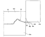
- I-2 In the first step, as shown in FIGS. 5 to 7, ironing and drawing are performed using an ironing device 50 in which a punch 50a, a die 50b and a pressing pad 50c are assembled to a press machine. Ironing may be performed after drawing.
- the die 50b is held with respect to the punch 50a and the pad 50c while the portion located on the inner side in the disk radial direction from the first material portion M1 of the disk material 30 is sandwiched between the punch 50a and the pad 50c.
- Ironing and drawing are performed by relatively moving only in the axial direction of the disk material 30 (the same direction as the axial direction of the disk 10).
- the punch 50a and the pad 50c may be moved relative to the die 50b.
- the thickness of the cylindrical portion 40 formed in the first step is such that the side surface of the punch 50a on the side facing the die 50b is a flat surface (a cylinder having a constant diameter) except for the thick portion 41 described later. Surface) or an uneven surface (an undulating surface, a non-planar surface, a cylindrical surface with a non-constant diameter), it may be constant (including substantially constant) or may not have a constant thickness Good.
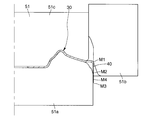
- the thick portion 41 may be formed between the fourth material portion M4 and the third material portion M3 of the disc material 30. .
- the thick part 41 is located at the axially inner end of the disc material 30 after the first step, and is a part having a plate thickness greater than the part adjacent to the thick part 41 in the axial direction.
- the thick portion 41 may extend from the second material portion M2 to the third material portion M3 of the disc material 30.
- the thick portion 41 is provided only between the fourth material portion M4 and the third material portion M3.
- the thick portion 41 is provided in order to suppress the occurrence of defects such as cracks in the disk material 30 in the second step (ii) (particularly during the diameter expansion step).
- the thick portion 41 has a disc flange portion thickness after the second step (ii) and the third step (iii). It becomes the meat part 13c.
- the thick portion 41 is the same as the second disc portion in the third step (iii). The thickness is reduced to the same thickness as that between the fourth disk portion D4.
- the thick portion 41 is at least a portion (hereinafter referred to as the ventilation portion 13a) as shown in FIGS. It is desirable to be provided in the deepest portion 42a of the concave portion 42). This is because, when the second step is a diameter expansion step, the stress applied to the deepest portion 42 a is the largest of the stress applied to the cylindrical portion 40 of the disk material 30.
- FIG. 15 shows a case where the thick part 41 is continuously provided over the entire circumference of the cylindrical part 40 including the deepest part 42a
- FIG. 16 shows the thick part 41 including the deepest part 42a
- FIG. 17 shows a case where the thick portion 41 is provided on the entire inner circumference in the axial direction including the deepest portion 42a.
- the thick part 41 is formed by, for example, the following methods (a1) and (a2). (A1) As shown in FIG. 12, the thick portion 41 is formed by providing a receding portion 50d on the punch 50a. The receding portion 50d is provided on the side surface of the punch 50a facing the die 50b so as to recede in a direction away from the die 50b. By providing the receding portion 50d, the thick portion 41 protruding in the direction of decreasing the inner diameter can be formed between the fourth material portion M4 and the third material portion M3 of the disc material 30. .
- the thickness of the thick portion 41 may be the same (including substantially the same) as the thickness of the disc material 30 before the first step, and is smaller than the thickness of the disc material 30 before the first step. May be.
- the thick portion 41 is configured such that after the die 50b reaches the intermediate portion in the axial direction of the cylindrical portion 40, the die 50b is stopped with respect to the punch 50a, and the die 50b is removed from the punch 50a. Molded by pulling.
- the portion of the disc material 30 that is ahead of the stop position of the die 50b (from the fourth material portion M4 to the third material portion M3 of the disc material 30) is not subjected to the ironing process, and the ironed portion (disc The first material part M1 to the fourth material part M4 of the material 30 are thicker in the direction of increasing the outer diameter.
- the thickness of the thick portion 41 is the same (including substantially the same) as the plate thickness of the disc material 30 before the first step.
- the thick portion 41 protruding inward in the radial direction in FIGS. 14 to 16 protrudes outward in the radial direction. Further, the thick portion 41 may protrude both inward in the radial direction and outward in the radial direction.
- the first step is to squeeze the first material portion M1 to the fourth material portion M4 of the disk material 30. If the thick portion 41 is not formed or the thick portion 41 is formed by the method (a1) (method shown in FIG. 12), the first step is performed. Is a step of forming the cylindrical portion 40 by ironing the first material portion M1 to the third material portion M3 of the disk material 30.
- the second step is performed simultaneously around the entire circumference by pressing.
- the second material portion M2 and the third material portion M3 of the disc material 30 and the first material portion of the disc material 30 are Both the material part M1 and the second material part M2 are expanded in diameter.
- the diameter between the first material portion M1 and the second material portion M2 of the disk material 30 may be reduced.
- a second material portion M2 of the disk material 30 is used by using a diameter changing device 51 in which a punch 51a and a pressing pad 51c are assembled to a press machine.
- the pad 51c is moved relative to the punch 51a only in the axial direction of the disk material 30 (the same direction as the axial direction of the disk 10), and the second material portion M2 and the third material part 3 of the disk material 30 are moved.
- the diameter of both the first material portion M1 and the second material portion M2 of the disk material 30 is expanded.
- the third step is a step of shaping the disk flange portion 13.
- the third step is performed simultaneously all around by pressing.
- the space between the second material portion M2 and the third material portion M3 of the disk material 30 is shaped.
- the first material part M1 and the second material part M2 of the disk material 30 may be shaped.
- shaping is performed using the shaping device 52 in which the punch 52a, the die 52b, and the pressing pad 52c are assembled in a press machine.
- the die 52b is held with respect to the punch 52a and the pad 52c while the portion located on the inner side in the disc radial direction from the first material portion M1 of the disc material 30 is sandwiched between the punch 52a and the pad 52c. Shaping is performed by relatively moving only in the axial direction of the disk material 30 (the same direction as the axial direction of the disk 10). The punch 52a and the pad 52c may be moved relative to the die 52b. (Iii-5)
- the shaping device 52 is used to shape the space between the second material portion M2 and the third material portion M3 of the disc material 30, and the shaping device 52 is used to form the disc.
- the thickness of the material 30 may be reduced by ironing between the second material part M2 and the third material part M3.
- the space between the second material portion M2 and the third material portion M3 of the disk material 30 may be formed to a constant thickness, or the fourth material portion M4 and the third material portion M3
- Between the second material portion M2 and the fourth material portion M4 of the disc material 30 and a thick disc flange portion 13c thicker than the thickness between the second material portion M2 and the fourth material portion M4 may be formed.
- the material part M3 may be formed so that the thickness of the material part M3 is the smallest between the second material part M2 and the third material part M3.
- the third step is to change the diameter by applying a machining force radially outward using a split mold 60 as shown in FIG. 18 (by performing the entire circumference simultaneously by expanding).
- the processing may be performed simultaneously with the second step.
- the third step may be omitted if sufficient accuracy can be secured in the second step.
- the manufacturing method of the wheel disk 10 is further performed before the first step (i ′) as shown in FIG. 19)
- the hub attachment portion corresponding portion 32, the hat inner peripheral portion corresponding portion 36, and the hat top portion corresponding portion 35 of the disc material 30 shown in FIG. 19A are respectively connected to the disc intermediate member 130 (disc material shown in FIG. 19B).
- the first ′ process may be performed after the third process. Further, the first 'step may not be performed.
- the first 1 'step is performed by drawing (simultaneous machining of the entire circumference by pressing).
- the hub attachment portion intermediate corresponding portion 112, the hat inner peripheral portion intermediate corresponding portion 116, and the hat top portion intermediate corresponding portion 115 of the disk intermediate member 130 (one form of the disk material 30) shown in FIG. Alternatively, it may be preformed.
- 19B and FIG. 19C are formed in the fourth step different from the first to third steps, respectively (the portion formed in the first 'step). It is desirable to be formed into a shape.
- the hub attachment portion intermediate corresponding portion 112 the hat inner peripheral portion intermediate corresponding portion 116, and the hat top portion intermediate corresponding portion 115 of the disk intermediate member 130 are respectively connected to the hub of the wheel disk 10.
- the mounting portion 12, the hat inner peripheral portion 16, and the hat top portion 15 are formed into final shapes.
- the fourth step may be before the third step.
- the disc flange portion 13 includes the disc flange portion thick portion 13c at least at the inner end portion in the disc axial direction of the disc flange portion 13 and at least a part of the disc circumferential direction.
- the assembly accuracy with the wheel rim 20 for an automobile can be improved.
- the rigidity of the disk 10 can be improved by projecting the disk flange thick part 13c radially inward. Further, when the disk 10 and the rim 20 are assembled, the plate thickness at the position where the disk flange portion 13 is welded becomes thick, so that welding becomes easy.
- the second material portion M2 and the third material portion are arranged such that the disc material portion between the second material portion M2 and the third material portion M3 has a larger diameter than the first material portion M1. Since there is a second step of changing the diameter of at least one of the disk material portion between M3 and the first material portion M1, the cylindrical portion molded in the first step is replaced with a disk flange portion. 13 and the outer periphery 17 of the hat.
- At least the disk material 30 portion between the third material portion M3 and the fourth material portion M4 is adjacent to the disk material 30 portion or the first plate thickness reducing portion 18a. Since it is formed into the thick portion 41 having a larger plate thickness, it is possible to suppress the occurrence of problems such as cracks in the disk in the second step (particularly during the diameter expansion step).
- the first embodiment of the present invention has the following unique parts.
- the thickness (thickness excluding the thick portion 41) of the cylindrical portion 40 formed in the first step is substantially constant as shown in FIG.
- the gap (minimum gap) between the punch 50a and the die 50b of the ironing device 50 is set to be narrower than the plate thickness of the disk material 30 before the first step.
- the gap (minimum gap) between the punch 52a and the die 52b of the shaping device 52 is set to be narrower than the plate thickness of the thickest flange portion between the second material portion M2 and the third material portion M3 after the second step. Has been. Further, the gap (minimum gap) between the punch 52a and the die 52b of the shaping device 52 is greater than the thickness of the thinnest flange portion between the second material portion M2 and the third material portion M3 after the second step. It may be set narrowly.
- the thick portion 41 is formed between the fourth material portion M4 and the third material portion M3 in the first step, and the plate thickness is larger than the plate thickness of the disc portion adjacent in the disc axial direction in the third step.
- the third process involves ironing between the second material part M2 and the third material part M3 of the disc material 30
- the third material part M2 and the second material part M2 of the disc material 30 are used in the third process.
- the disk flange portion 13 of the wheel disk 10 for an automobile can be formed with high accuracy.
- the second embodiment of the present invention has the following unique parts.
- the shaping device 52 is used to place between the second material part M2 and the third material part M3 of the disc material 30 and the first material part M1 and the second material part of the disc material 30.
- the material portion M2 is only drawn and the disk material 30 is not ironed.
- the thick part 41 is formed between the fourth material part M4 and the third material part M3 in the first process, and the thickness process is not performed on the thick part 41 in the third process.
- the ironing process is not performed between the second material portion M2 and the third material portion M3 of the disc material 30. Therefore, in the third step, the second material portion M2 of the disc material 30 and Compared with the case of ironing with the second material part M3, the processing cost is not severe, so that the mold cost can be reduced.
- the third embodiment of the present invention has the following unique parts.
- the thickness of the cylindrical portion 40 formed in the first step is formed to be at least two types.
- the cylindrical portion 40 is formed in two thicknesses by providing one stepped portion (including a tapered portion) 50e on the side surface of the punch 50a on the side facing the die 50b.
- a plurality of stepped portions 50e may be provided and molded with two or more types of thickness.
- the plate between the second material part M2 and the third material part M3 of the disc material 30 is between the first material part M1 and the second material part M2 of the disc material 30. It is smaller than the thickness.
- the gap (minimum gap) between the punch portion 50f on the axially outer side from the stepped portion 50e and the die 50b is set to be narrower than the plate thickness of the disc material 30 before the first step.
- the gap (minimum gap) between the punch portion 50g and the die 50b located on the inner side in the axial direction from the stepped portion 50e is set narrower than the gap (minimum gap) between the punch portion 50f and the die 50b.
- the thickness between the second material portion M2 and the third material portion M3 of the disc material 30 is larger than the plate thickness between the first material portion M1 and the second material portion M2 of the disc material 30. It may be large.
- the gap (minimum gap) between the punch portion 50g located on the inner side in the axial direction from the stepped portion 50e and the die 50b is set to be narrower than the plate thickness of the disc material 30 before the first step. It may be set widely, may be set widely, and may be set the same. Further, it is set wider than the gap (minimum gap) between the punch portion 50f on the axially outer side from the stepped portion 50e and the die 50b. The gap (minimum gap) between the punch portion 50f on the axially outer side from the stepped portion 50e and the die 50b is set to be narrower than the plate thickness of the disc material 30 before the first step.
- the stepped portion 50e may be in the axial direction, between the first material portion M1 and the second material portion M2, or between the second material portion M2 and the third material portion M3.
- the shaping device 52 is used to place the second material portion M2 and the third material portion M3 of the disc material 30 between the first material portion M1 and the second material portion M3 of the disc material 30. Both the material portion M2 and the material portion M2 are shaped, and the disc material 30 is not ironed. However, ironing may be performed.
- the part ironed in the first step has two or more types of thickness
- the part ironed in the first step needs to have both strength and weight reduction compared to the case where the part ironed only has one type of thickness. It is possible to easily manufacture the automobile wheel disk 10 having a large thickness.
- the fourth embodiment of the present invention has the following unique parts.
- (A) The outer diameter of the cylindrical portion 40 formed in the first step is formed so as to be substantially the same as the outer diameter of the automobile wheel disk 10.
- the following specific effects can be obtained.
- the second step between the second material part M2 and the third material part M3 of the disc material 30 after the ironing process, and between the first material part M1 and the second material part M2 of the disc material 30.
- the second step between the second material portion M2 and the third material portion M3 of the disc material 30 after the ironing process, and in the first step of the disc material 30 Compared with the case where the diameter is increased between the material portion M1 and the second material portion M2, the ironed portion is not expanded, so that cracking is less likely to occur.
Abstract
Description
特許文献1,2に開示された製造方法では、径方向の寸法が実質的に一定で軸方向に平行な部位であり軸方向長さに限界のあるディスクフランジ部のみをしごき加工により板厚を減少させている。そのため、ディスクの軽量化が不十分であった。 However, the conventional method for manufacturing a wheel disk for automobile has the following problems.
In the manufacturing methods disclosed in
(1) 平板状のディスク素材から製造されており、
ハブ取付け部と、ディスクフランジ部と、前記ハブ取付け部と前記ディスクフランジ部とをつなぐハット部と、を有し、
前記ハット部が、ディスク軸方向外側に突出するハット頂部と、該ハット頂部と前記ハブ取付け部とをつなぐハット内周部と、前記ハット頂部と前記ディスクフランジ部とをつなぐハット外周部と、を有する、
自動車用ホイールディスクであって、
前記ハット外周部に、前記ディスク素材の板厚より板厚が小の第1の板厚減少部が設けられている、
自動車用ホイールディスク。
(2) 前記ディスクフランジ部に、前記ディスク素材の板厚より板厚が小の第2の板厚減少部が設けられている、(1)記載の自動車用ホイールディスク。
(3) 前記ディスクフランジ部は、該ディスクフランジ部の少なくともディスク軸方向内側端部でディスク周方向の少なくとも一部に、ディスクフランジ部厚肉部を備えている、(1)または(2)記載の自動車用ホイールディスク。
(4) 前記ハット外周部には飾り穴が形成されており、
前記第1の板厚減少部は、前記ハット外周部の、少なくとも前記飾り穴よりディスク半径方向外側に隔たった部分に設けられている、(1)~(3)のいずれか1つに記載の自動車用ホイールディスク。
(5) 前記第2の板厚減少部は、ディスク軸方向で前記ディスクフランジ部の全域に設けられている、(2)~(4)のいずれか1つに記載の自動車用ホイールディスク。
(6) 〔実施例1~4〕
自動車用のホイールディスクをディスク素材から製造する、自動車用ホイールディスクの製造方法であって、
ホイールディスクは、ハット頂部とハット外周部とハット内周部を備えるハット部と、ディスクフランジ部と、ハット頂部よりディスク半径方向外側でディスクフランジ部よりディスク半径方向内側にある第1のディスク部位(D1)と、ハット外周部とディスクフランジ部との境界にある第2のディスク部位(D2)と、ディスクフランジ部のディスク軸方向内側端にある第3のディスク部位(D3)と、第2のディスク部位(D2)よりディスク軸方向内側で第3のディスク部位(D3)よりディスク軸方向外側にある第4のディスク部位(D4)と、を備えており、
ディスク素材は、第1のディスク部位(D1)に対応する第1の素材部位(M1)と、第2のディスク部位(D2)に対応する第2の素材部位(M2)と、第3のディスク部位(D3)に対応する第3の素材部位(M3)と、第4のディスク部位(D4)に対応する第4の素材部位(M4)と、を備えており、
少なくともM1からM2までの一部または全部のディスク素材部分をしごき加工し、しごき加工後の板厚がしごき加工前の板厚より薄い円筒状部を成形する第1の工程と、
M2とM3との間のディスク素材部分が第1の素材部位M1よりも大径になるように、M2とM3との間のディスク素材部分と、第1の素材部位M1と、の少なくともいずれか一方の径を変える第2の工程と、
を有する自動車用ホイールディスクの製造方法。
(7)〔実施例1~3〕
第2の工程では、M2とM3との間のディスク素材部分と、M1とM2との間のディスク素材部分と、の両方を拡径する、(6)記載の自動車用ホイールディスクの製造方法。
(8)〔実施例1~4〕
第1の工程で、さらにM2からM4またはM2からM3までのディスク素材部分をしごき加工する、(6)または(7)記載の自動車用ホイールディスクの製造方法。
(9)〔実施例1~4〕
第1の工程で、少なくともM3とM4との間のディスク素材部分が、隣接するディスク素材部分または第1の板厚減少部よりも板厚が厚い厚肉部に成形される、(8)記載の自動車用ホイールディスクの製造方法。
(10)〔実施例1~4〕
第2の工程の後に、M2とM3との間のディスク素材部分を整形して最終のディスクフランジ部形状にする第3の工程を有する、(6)~(9)のいずれか1つに記載の自動車用ホイールディスクの製造方法。
(11)〔実施例1~4〕
第3の工程において、M2からM4またはM2からM3までのディスク素材部分の少なくとも一部をしごき加工する、(10)記載の自動車用ホイールディスクの製造方法。
(12)〔実施例1~4〕
ホイールディスクは、ハブ取付け部を備えており、
ディスク素材は、ハブ取付け部対応部と、ハット頂部対応部とハット外周部対応部とハット内周部対応部を備えるハット部対応部と、を備えており、
第1の工程の前に、ディスク素材のハブ取付け部対応部、ハット内周部対応部、ハット頂部対応部を予備成形する工程を有する、(6)~(11)のいずれか1つに記載の自動車用ホイールディスクの製造方法。 The present invention for achieving the above object is as follows.
(1) Manufactured from flat disk material,
A hub attachment portion, a disc flange portion, and a hat portion connecting the hub attachment portion and the disc flange portion;
A hat top portion protruding outward in the disk axial direction; a hat inner peripheral portion connecting the hat top portion and the hub mounting portion; and a hat outer peripheral portion connecting the hat top portion and the disc flange portion. Have
An automotive wheel disc,
In the outer periphery of the hat, a first plate thickness reduction portion having a plate thickness smaller than the plate thickness of the disk material is provided,
Wheel disc for automobile.
(2) The wheel disc for automobiles according to (1), wherein the disc flange portion is provided with a second plate thickness reduction portion having a plate thickness smaller than the plate thickness of the disc material.
(3) The disk flange portion includes a disk flange portion thick portion at least at a part in the disk circumferential direction at an inner end portion in the disk axial direction of the disk flange portion. Automotive wheel disc.
(4) A decorative hole is formed on the outer periphery of the hat,
The first plate thickness reduction portion is provided in any one of (1) to (3), which is provided at a portion of the outer periphery of the hat that is spaced at least on the outer side in the disk radial direction from the decoration hole. Wheel disc for automobile.
(5) The vehicle wheel disc according to any one of (2) to (4), wherein the second plate thickness reduction portion is provided in the entire region of the disc flange portion in the disc axial direction.
(6) [Examples 1 to 4]
A method for manufacturing a wheel disk for automobiles, wherein a wheel disk for automobiles is manufactured from a disk material,
The wheel disc includes a hat top portion, a hat outer peripheral portion, and a hat inner peripheral portion, a disc flange portion, and a first disc portion located outside the disc radial direction from the hat top portion and inside the disc radial direction from the disc flange portion ( D1), a second disk part (D2) at the boundary between the outer periphery of the hat and the disk flange part, a third disk part (D3) at the inner end in the disk axial direction of the disk flange part, A fourth disk portion (D4) located on the inner side in the disk axial direction from the disk portion (D2) and on the outer side in the disk axial direction from the third disk portion (D3),
The disc material includes a first material portion (M1) corresponding to the first disc portion (D1), a second material portion (M2) corresponding to the second disc portion (D2), and a third disc. A third material part (M3) corresponding to the part (D3) and a fourth material part (M4) corresponding to the fourth disk part (D4);
A first step of ironing at least a part or all of the disk material part from M1 to M2, and forming a cylindrical part whose plate thickness after ironing is thinner than the plate thickness before ironing;
At least one of the disk material portion between M2 and M3 and the first material portion M1 so that the disk material portion between M2 and M3 has a larger diameter than the first material portion M1. A second step of changing one diameter;
A method for manufacturing a wheel disk for automobiles having
(7) [Examples 1 to 3]
In the second step, the diameter of both the disk material portion between M2 and M3 and the disk material portion between M1 and M2 is increased, and the method for manufacturing a wheel disk for an automobile according to (6).
(8) [Examples 1 to 4]
The manufacturing method of the wheel disc for automobiles according to (6) or (7), wherein in the first step, the disc material portion from M2 to M4 or M2 to M3 is further ironed.
(9) [Examples 1 to 4]
In the first step, at least a disk material portion between M3 and M4 is formed into a thick portion having a plate thickness larger than that of the adjacent disk material portion or the first plate thickness reduction portion (8) Of manufacturing wheel discs for automobiles.
(10) [Examples 1 to 4]
The method according to any one of (6) to (9), further comprising a third step of shaping the disc material portion between M2 and M3 into a final disc flange shape after the second step. Of manufacturing wheel discs for automobiles.
(11) [Examples 1 to 4]
In the third step, at least a part of the disk material portion from M2 to M4 or M2 to M3 is ironed, and the method for manufacturing a wheel disk for an automobile according to (10).
(12) [Examples 1 to 4]
The wheel disc has a hub attachment,
The disc material includes a hub mounting portion corresponding portion, a hat top corresponding portion, a hat outer peripheral corresponding portion, and a hat inner corresponding portion including a hat inner peripheral corresponding portion,
(6) to (11), including a step of preforming the hub attachment portion corresponding portion, the hat inner peripheral portion corresponding portion, and the hat top portion corresponding portion of the disk material before the first step. Of manufacturing wheel discs for automobiles.
また、M2とM3との間のディスク素材部分が第1の素材部位M1よりも大径になるように、M2とM3との間のディスク素材部分と、第1の素材部位M1と、の少なくともいずれか一方の径を変える第2の工程を有するため、第1の工程で成形した円筒状部を、ハット外周部に成形できる。 According to the method for manufacturing a wheel disk for automobile of (6) above, at least a part or all of the disk material portion from M1 to M2 is ironed, and the thickness after the ironing is thinner than the thickness before the ironing. Since it has the 1st process which shape | molds a cylindrical part, a plate | board thickness reduction | decrease part whose plate | board thickness is smaller than the disk raw material before a 1st process can be provided in a hat outer peripheral part. For this reason, it is possible to effectively and more reliably reduce the weight of the wheel disc for an automobile as compared with the case where the thickness reduction portion is provided only in the disc flange portion.
Further, at least of the disk material portion between M2 and M3 and the first material portion M1 so that the disk material portion between M2 and M3 has a larger diameter than the first material portion M1. Since it has the 2nd process of changing any one diameter, the cylindrical part shape-formed by the 1st process can be shape | molded in a hat outer peripheral part.
本発明実施例の自動車用ホイールディスク(以下、単に、ホイールディスクまたはディスクともいう)10は、図2に示すように、シングル取り付けタイプ(ハット部を有し乗用車などで使用されるタイプ)のディスクである。ディスク10は、図25に示すようなダブル取り付けタイプ(ハット部を有さず基本的にトラック・バスなどで使用されるタイプ)のディスク100ではない。ディスク10は、平板状のディスク素材から製造されるディスクが対象である。ディスク10は、たとえばスチール製である。ただし、ディスク10は、スチール製でなくてもよく、アルミ合金製、チタン合金製、マグネシウム合金製等であってもよい。ディスク10は、環状のリム(図示略のタイヤを保持する部分)20とは別に製造されており、リム20と溶接、リベット、接着等で接合されてホイール1になる。 First, an automotive wheel disk according to an embodiment of the present invention will be described with reference to the drawings.
As shown in FIG. 2, a vehicle wheel disk (hereinafter, also simply referred to as a wheel disk or a disk) 10 according to an embodiment of the present invention is a single attachment type (a type having a hat portion and used in a passenger car). It is. The
ディスク10は、ハット頂部15よりディスク半径方向外側でディスクフランジ部13よりディスク半径方向内側にある第1のディスク部位(D1)と、ハット外周部17とディスクフランジ部13との境界にある第2のディスク部位(D2)と、ディスクフランジ部13のディスク軸方向内側端にある第3のディスク部位(D3)と、第2のディスク部位(D2)よりディスク軸方向内側で第3のディスク部位(D3)よりディスク軸方向外側にある第4のディスク部位(D4)と、を有する。ディスクフランジ部13全体が後述のディスクフランジ部厚肉部13cとなる場合、第2のディスク部位(D2)と第4のディスク部位(D4)は一致する。なお、図中Aは、ディスク軸方向内側を示している。 The
The
ハブ取付け部12は、ハブ穴11の周囲に設けられている。ハブ取付け部12は、平板状または略平板状であり、ディスク軸方向(ホイール軸方向)と直交またはほぼ直交する平面内にある。ハブ取付け部12のディスク半径方向中間部にはハブ取付けボルト穴12aが複数設けられている。ハブ取付けボルト穴12aは、ディスク周方向(ホイール周方向)に同心円上等間隔にたとえば4個設けられている。ただし、ハブ取付けボルト穴12aの数は、4個に限定されるものではなく、3個であってもよく、5個以上であってもよい。車両のハブから延びてくるハブ取付けボルト(両方共に図示略)をハブ取付けボルト穴12aに挿通し、ハブ取付けボルトに図示略のハブナットを螺合することにより、ディスク10(ホイール1)はハブに固定される。ただし、ディスク10(ホイール1)は、ハブ取付け部12に開けられたタップ穴にハブボルトにて螺合することによりハブに固定されてもよい。ハブ取り付け部12の平坦な部分であるハブ取付け部平坦部12cは、しごき加工による薄肉化を行わないので、製品となったときの厚さは、ディスク素材の厚さとほぼ同じである。 As shown in FIG. 1, the
The
ディスクフランジ部13のディスク軸方向内側端(第3のディスク部位D3)は、図2、図3(c)に示すように、ディスク周方向に全周にわたって1つの平面内に位置していてもよく、図11(c)に示すように、ディスク軸方向外側に凹状に湾曲するベンチレーション部13aを有していてもよい。
ディスクフランジ部13は、図2に示すように、リム20のドロップ部24に嵌入されドロップ部24に接合(固定、溶接)される部分である。ディスクフランジ部13は、ディスク半径方向断面視で、ディスク軸方向内側端D3からディスク軸方向外側にディスク10の内周面および外周面が共にディスク10のディスク軸方向と交わる方向へ傾き始めるまでのディスク部分である。 As shown in FIG. 2, the
As shown in FIGS. 2 and 3C, the inner end of the
As shown in FIG. 2, the
飾り穴19は、ハット外周部17のディスク半径方向中間部に設けられている。飾り穴19は、図1に示すように、ディスク周方向に等間隔に複数設けられている。ただし、飾り穴19は無くてもよく、ディスク周方向に不等間隔に設けられていてもよく、1つのみ設けられていてもよい。
ハット外周部17のうち、後述する第1の板厚減少部18a以外の部分(例えば飾り穴19よりも径方向内側の部分)は、プレスによる大きな塑性変形もなく、しごき加工による薄肉化を行わないので、自動車用ホイールディスクとなったときの厚さは、ディスク素材の厚さとほぼ同じである。 A
The
Of the outer
板厚減少部18は、ディスク半径方向でディスク10の外径の80%を含んで80%より外側のみに設けられていることが望ましいが、板材の性質により80%には限らない。これは、板厚減少部18を有するディスク10を割れが無く成形できるようにするためである。 The plate
The plate
ディスクフランジ部厚肉部13cの厚さの最大値は、ディスク素材板厚と同じであってもよく、ディスク素材板厚よりも大であってもよく、ディスク素材板厚より小であってもよい。
第1のディスク部位D1と第2のディスク部位D2の間の断面形状は図24のように直線状であってもよいし、全体が大きな円弧状であってもよいし、その他の形状であってもよい。 The disc flange portion
The maximum value of the thickness of the disc flange portion
The cross-sectional shape between the first disk part D1 and the second disk part D2 may be a straight line as shown in FIG. 24, a large arc shape as a whole, or other shapes. May be.
本発明全実施例にわたって共通する部分には、本発明全実施例にわたって同じ符号を付してある。
まず、本発明全実施例にわたって共通する部分を説明する。 Next, a method for manufacturing the
Portions common to all the embodiments of the present invention are denoted by the same reference numerals throughout the embodiments of the present invention.
First, parts common to all the embodiments of the present invention will be described.
ハット部対応部34は、ディスク素材30をディスク10に製造したときに、ハット部14となる部分である。
ハット頂部対応部35は、ディスク素材30をディスク10に製造したときに、ハット頂部15となる部分である。
ハット内周部対応部36は、ディスク素材30をディスク10に製造したときに、ハット内周部16となる部分である。
ハット外周部対応部37は、ディスク素材30をディスク10に製造したときに、ハット外周部17となる部分である。
飾り穴対応部39は、ディスク素材30をディスク10に製造する際に打ち抜かれて飾り穴19となる部分である。
第1の素材部位M1は、ディスク素材30をディスク10に製造したときに、第1のディスク部位D1となる部分である。
第2の素材部位M2は、ディスク素材30をディスク10に製造したときに、第2のディスク部位D2となる部分である。
第3の素材部位M3は、ディスク素材30をディスク10に製造したときに、第3のディスク部位D3となる部分である。
第4の素材部位M4は、ディスク素材30をディスク10に製造したときに、第4のディスク部位D4となる部分である。 The disc flange
The hat
The hat
The hat inner
The hat outer peripheral
The decorative
The first material part M1 is a part that becomes the first disk part D1 when the
The second material part M2 is a part that becomes the second disk part D2 when the
The third material part M3 is a part that becomes the third disk part D3 when the
The fourth material part M4 is a part that becomes the fourth disk part D4 when the
(i)図5~図7に示すように、ディスク素材30の少なくとも第1の素材部位M1から第2の素材部位M2までの一部または全部をしごき加工し、しごき加工後の板厚がしごき加工前の板厚より薄い円筒状部40を成形する第1の工程(しごき絞り加工工程)と、
(ii)第1の工程の後に、図8、図9に示すように、ディスク素材30の第2の素材部位M2と第3の素材部位M3との間がディスク素材30の第1の素材部位M1よりも大径になるように、ディスク素材30の第2の素材部位M2と第3の素材部位M3との間と、ディスク素材30の第1の素材部位M1と、の少なくともいずれか一方の径を変える第2の工程(径変更工程)と、
を有する。第1の工程では、図7に示すように、第1の素材部位M1から第3の素材部位M3までの全部をしごき加工してもよい。
ホイールディスク10の製造方法は、さらに、上記(ii)の第2の工程の後に、(iii)図10に示すように、ディスク素材30の第2の素材部位M2と第3の素材部位M3との間を整形して最終のディスクフランジ部13形状にする第3の工程(整形工程)を有する。
なお、本発明実施例および図示例では、上記(i)の第1の工程で、第1の素材部位M1から第4の素材部位M4または第1の素材部位M1から第3の素材部位M3までをしごき加工する場合を示す。 The manufacturing method of the
(I) As shown in FIGS. 5 to 7, at least a part or all of the
(Ii) After the first step, as shown in FIGS. 8 and 9, the first material portion of the
Have In the first step, as shown in FIG. 7, all of the first material portion M1 to the third material portion M3 may be ironed.
The method for manufacturing the
In the embodiment of the present invention and the illustrated example, from the first material part M1 to the fourth material part M4 or from the first material part M1 to the third material part M3 in the first step (i) above. The case of ironing is shown.
(i-1)第1の工程は、プレスによって全周同時に行なわれる。しごき絞り加工は1回に限らず、型交換を含めて複数回行ってもよい。
(i-2)第1の工程では、図5~図7に示すように、パンチ50aとダイス50bと押さえパッド50cとをプレス機に組付けたしごき装置50を用いてしごき絞り加工を行なう。絞り加工を行った後しごき加工を行ってもよい。第1の工程では、ディスク素材30の第1の素材部位M1よりディスク半径方向内側に位置する部分を、パンチ50aとパッド50cとで挟持しつつ、ダイス50bを、パンチ50aおよびパッド50cに対してディスク素材30の軸方向(ディスク10の軸方向と同方向)にのみ相対動させてしごき絞り加工する。なお、パンチ50aおよびパッド50cをダイス50bに対して相対動させてもよい。
(i-3)第1の工程で成形される円筒状部40の厚みは、後述する厚肉部41を除いて、パンチ50aのダイス50bに対向する側の側面を平面(径が一定の円柱面)または凹凸のある面(起伏のある面、平面でない面、径が一定でない円筒面)とすることで、一定(略一定を含む)とされていてもよく厚さが一定でなくてもよい。 Regarding the first step (i) (i-1) The first step is performed simultaneously on the entire circumference by pressing. The ironing and drawing process is not limited to one time, and may be performed a plurality of times including mold change.
(I-2) In the first step, as shown in FIGS. 5 to 7, ironing and drawing are performed using an
(I-3) The thickness of the
厚肉部41は、図11に示すように、ディスク素材30からベンチレーション部13aを有するディスク10を製造する場合、図15~図17に示すように、少なくともベンチレーション部13aとなる部分(以下、凹部という)42の最深部42aに設けられることが望ましい。第2の工程が拡径工程である場合、ディスク素材30の円筒状部40にかかる応力の中で最深部42aにかかる応力が最大だからである。なお、図15は、厚肉部41が最深部42aを含んで円筒状部40の全周にわたって連続して設けられる場合を示しており、図16は、厚肉部41が最深部42aを含んで凹部42に設けられる場合を示しており、図17は、厚肉部41が最深部42aを含む軸方向内側全周に設けられる場合を示している。 As shown in FIG. 3, when the
As shown in FIG. 11, when the
(a1)厚肉部41は、図12に示すように、パンチ50aに後退部50dを設けることで成形される。後退部50dは、パンチ50aの、ダイス50bに対向する側の側面に、ダイス50bから離れる方向に後退して設けられる。後退部50dが設けられることにより、ディスク素材30の第4の素材部位M4から第3の素材部位M3までの間に、内径を小にする方向に突出した厚肉部41を成形することができる。厚肉部41の厚みは、第1の工程前のディスク素材30の板厚と同じ(略同じを含む)であってもよく、第1の工程前のディスク素材30の板厚より小であってもよい。
(a2)厚肉部41は、図13に示すように、ダイス50bが円筒状部40の軸方向中間部に達した後、ダイス50bをパンチ50aに対して停止させてダイス50bをパンチ50aから抜くことで成形される。ディスク素材30の、ダイス50bの停止位置より先側にある部分(ディスク素材30の第4の素材部位M4から第3の素材部位M3まで)は、しごき加工されず、しごき加工された部分(ディスク素材30の第1の素材部位M1から第4の素材部位M4まで)に比べて外径を大にする方向に厚肉となる。厚肉部41の厚みは、第1の工程前のディスク素材30の板厚と同じ(略同じを含む)である。この場合、図14~図16で径方向内向きに突出している厚肉部41は、径方向外向きに突出する。また、厚肉部41は径方向内向きと径方向外向きの両方に突出していてもよい。 The
(A1) As shown in FIG. 12, the
(A2) As shown in FIG. 13, the
(ii-1)第2の工程は、プレスによって全周同時に行なわれる。
(ii-2)第2の工程では、図8、図9に示すように、ディスク素材30の第2の素材部位M2と第3の素材部位M3との間と、ディスク素材30の第1の素材部位M1と第2の素材部位M2との間と、の両方を拡径する。ただし、第2の工程では、ディスク素材30の第1の素材部位M1と第2の素材部位M2との間を縮径してもよい。
(ii-3)第2の工程では、図8に示すように、パンチ51aと押さえパッド51cとをプレス機に組付けた径変更装置51を用いて、ディスク素材30の第2の素材部位M2と第3の素材部位M3との間と、ディスク素材30の第1の素材部位M1と第2の素材部位M2との間と、の両方を拡径する。第2の工程では、パッド51cをパンチ51aに対してディスク素材30の軸方向(ディスク10の軸方向と同方向)にのみ相対動させて、ディスク素材30の第2の素材部位M2と第3の素材部位M3との間と、ディスク素材30の第1の素材部位M1と第2の素材部位M2との間と、の両方を拡径する。
(ii-4)第2の工程では、プレスによる軸方向の加工のほかに、図18のような分割型60を用いて径方向外向きにプレスにより分割金型を動かし、加工力を作用させて径を変更する加工を行ってもよい。 Regarding the second step (ii) (ii-1) The second step is performed simultaneously around the entire circumference by pressing.
(Ii-2) In the second step, as shown in FIGS. 8 and 9, the second material portion M2 and the third material portion M3 of the
(Ii-3) In the second step, as shown in FIG. 8, a second material portion M2 of the
(Ii-4) In the second step, in addition to the axial processing by the press, the split die 60 is moved radially outward by using the split die 60 as shown in FIG. 18 to apply the processing force. The diameter may be changed.
(iii-1)第3の工程は、ディスクフランジ部13を整形する工程である。
(iii-2)第3の工程は、プレスによって全周同時に行なわれる。
(iii-3)第3の工程では、図10に示すように、ディスク素材30の第2の素材部位M2と第3の素材部位M3との間を整形加工する。ディスク素材30の第1の素材部位M1と第2の素材部位M2との間も整形加工してもよい。
(iii-4)第3の工程では、パンチ52aとダイス52bと押さえパッド52cとをプレス機に組付けた整形装置52を用いて整形加工を行なう。第3の工程では、ディスク素材30の第1の素材部位M1よりディスク半径方向内側に位置する部分を、パンチ52aとパッド52cとで挟持しつつ、ダイス52bを、パンチ52aおよびパッド52cに対してディスク素材30の軸方向(ディスク10の軸方向と同方向)にのみ相対動させて整形加工する。なお、パンチ52aおよびパッド52cをダイス52bに対して相対動させてもよい。
(iii-5)第3の工程では、整形装置52を用いてディスク素材30の第2の素材部位M2と第3の素材部位M3との間を整形加工するとともに、整形装置52を用いてディスク素材30の第2の素材部位M2と第3の素材部位M3との間をしごき加工して板厚を減少させてもよい。この場合、ディスク素材30の第2の素材部位M2と第3の素材部位M3との間が一定の厚さに成形されてもよいし、第4の素材部位M4と第3の素材部位M3との間にディスク素材30の第2の素材部位M2と第4の素材部位M4との間の厚さよりも厚いディスクフランジ部厚肉部13cが形成するように成形されてもよいし、第3の素材部位M3の厚さが、第2の素材部位M2から第3の素材部位M3の間で最も薄くなるように成形されてもよい。
(iii-6)第3の工程は、図18のような分割型60を用いて径方向外向きに加工力を作用させて径を変更することで(エキスパンドによって全周同時に行なわれることで)、第2の工程と同時に加工を行ってもよい。
(iii-7)第3の工程は、第2の工程で十分な精度が確保できれば省略してもよい。 Regarding the third step (iii) (iii-1) The third step is a step of shaping the
(Iii-2) The third step is performed simultaneously all around by pressing.
(Iii-3) In the third step, as shown in FIG. 10, the space between the second material portion M2 and the third material portion M3 of the
(Iii-4) In the third step, shaping is performed using the
(Iii-5) In the third step, the shaping
(Iii-6) The third step is to change the diameter by applying a machining force radially outward using a
(Iii-7) The third step may be omitted if sufficient accuracy can be secured in the second step.
第1´の工程は、図19(c)に示すディスク中間部材130(ディスク素材30の一形態)のハブ取付け部中間対応部112、ハット内周部中間対応部116、ハット頂部中間対応部115に、予備成形するものであってもよい。
図19(b)、図19(c)の形状に成形された部分(第1´の工程で成形された部分)は、それぞれ、第1~第3の工程とは異なる第4の工程で最終形状に成形されることが望ましい。 In addition to the first to third steps (steps (i) to (iii) above), the manufacturing method of the
In the first step, the hub attachment portion intermediate
19B and FIG. 19C are formed in the fourth step different from the first to third steps, respectively (the portion formed in the first 'step). It is desirable to be formed into a shape.
第4の工程では、ディスク中間部材130のハブ取付け部中間対応部112、ハット内周部中間対応部116、ハット頂部中間対応部115を、それぞれ、ホイールディスク10のハブ取付け部12、ハット内周部16、ハット頂部15の最終形状に成形する。第4の工程は第3の工程より前にあってもよい。 Regarding the fourth step, in the fourth step, the hub attachment portion intermediate
(A-1)ハット外周部17に、ディスク素材30の板厚より板厚が小の第1の板厚減少部18aが設けられているため、自動車用ホイールディスク10の軽量化を効果的に、より確実に図ることができる。 (A) Effects of the
(B-1)ディスク素材30の少なくとも第1の素材部位M1から第2の素材部位M2までの一部または全部のディスク素材部分をしごき加工し、しごき加工後の板厚がしごき加工前の板厚より薄い円筒状部40を成形する第1の工程を有するため、ハット外周部17に、第1の工程前のディスク素材30より板厚が小の板厚減少部18を設けることができる。そのため、ディスクフランジ部13のみに板厚減少部18が設けられている場合に比べて、自動車用ホイールディスク10の軽量化を効果的に、より確実に図ることができる。
また、第2の素材部位M2と第3の素材部位M3との間のディスク素材部分が第1の素材部位M1よりも大径になるように、第2の素材部位M2と第3の素材部位M3との間のディスク素材部分と、第1の素材部位M1と、の少なくともいずれか一方の径を変える第2の工程を有するため、第1の工程で成形した円筒状部を、ディスクフランジ部13とハット外周部17に成形できる。 (B) Effects common to the method of manufacturing the
Further, the second material portion M2 and the third material portion are arranged such that the disc material portion between the second material portion M2 and the third material portion M3 has a larger diameter than the first material portion M1. Since there is a second step of changing the diameter of at least one of the disk material portion between M3 and the first material portion M1, the cylindrical portion molded in the first step is replaced with a disk flange portion. 13 and the
本発明実施例1では、つぎの特有な部分を有する。
(a)第1の工程で成形される円筒状部40の厚み(厚肉部41を除く厚み)は、図7に示すように、ほぼ一定とされている。しごき装置50のパンチ50aとダイス50bとの隙間(最小隙間)は、第1の工程前のディスク素材30の板厚より狭く設定されている。
(b)第3の工程では、図10に示すように、整形装置52を用いてディスク素材30の第2の素材部位M2から第3の素材部位M3までの少なくとも一部をしごき加工して板厚を減少させている。整形装置52のパンチ52aとダイス52bとの隙間(最小隙間)は、第2の工程後の第2の素材部位M2から第3の素材部位M3の間の最も厚いフランジ部の板厚より狭く設定されている。また、整形装置52のパンチ52aとダイス52bとの隙間(最小隙間)は、第2の工程後の第2の素材部位M2から第3の素材部位M3の間の最も薄いフランジ部の板厚より狭く設定されていてもよい。
なお、第1の工程で第4の素材部位M4から第3の素材部位M3の間に厚肉部41を成形し、第3の工程でディスク軸方向に隣接するディスク部分の板厚より板厚が大となるようにしごき加工することで、ディスクフランジ部厚肉部13cを有するディスク10とすることができる。 [Production Example 1] (FIGS. 3 to 19)
The first embodiment of the present invention has the following unique parts.
(A) The thickness (thickness excluding the thick portion 41) of the
(B) In the third step, as shown in FIG. 10, at least a part of the
The
第3の工程では、ディスク素材30の第2の素材部位M2と第3の素材部位M3との間のしごき加工を伴うため、第3の工程でディスク素材30の第2の素材部位M2と第2の素材部位M3との間のしごき加工を伴わない場合に比べて、自動車用ホイールディスク10のディスクフランジ部13を高精度に成形することができる。 In the first embodiment of the present invention, the following specific effects can be obtained.
Since the third process involves ironing between the second material part M2 and the third material part M3 of the
本発明実施例2では、つぎの特有な部分を有する。
(a)第3の工程では、整形装置52を用いてディスク素材30の第2の素材部位M2と第3の素材部位M3との間と、ディスク素材30の第1の素材部位M1と第2の素材部位M2との間と、の両方を絞り加工するだけであり、ディスク素材30をしごき加工していない。
なお、第1の工程で第4の素材部位M4から第3の素材部位M3の間に厚肉部41を成形し、第3の工程では、厚肉部41に対して厚さの加工をしない整形加工をすることで、ディスクフランジ部厚肉部13cを有するディスク10とすることができる。 [Production Example 2] (FIG. 20)
The second embodiment of the present invention has the following unique parts.
(A) In the third step, the shaping
The
第3の工程では、ディスク素材30の第2の素材部位M2と第3の素材部位M3との間のしごき加工を伴わないため、第3の工程でディスク素材30の第2の素材部位M2と第2の素材部位M3との間のしごき加工を伴う場合に比べて、加工条件が厳しくないため金型費用を安価に抑えることができる。 In the second embodiment of the present invention, the following specific effects can be obtained.
In the third step, the ironing process is not performed between the second material portion M2 and the third material portion M3 of the
本発明実施例3では、つぎの特有な部分を有する。
(a)第1の工程で成形される円筒状部40の厚み(厚肉部41を除く厚み)は、図21に示すように、少なくとも2種類の厚さとなるように成形されている。円筒状部40の厚みは、パンチ50aの、ダイス50bに対向する側の側面に段付部(テーパ部を含む)50eを1つ設けることで、2種類の厚さで成形されている。段付部50eを複数設けて、2種類以上の厚さで成形してもよい。
図21の例では、ディスク素材30の第2の素材部位M2と第3の素材部位M3との間が、ディスク素材30の第1の素材部位M1と第2の素材部位M2との間の板厚に比べて小となっている。段付部50eより軸方向外側にあるパンチ部分50fと、ダイス50bとの隙間(最小隙間)は、第1の工程前のディスク素材30の板厚より狭く設定されている。また、段付部50eより軸方向内側にあるパンチ部分50gと、ダイス50bとの隙間(最小隙間)は、パンチ部分50fと、ダイス50bとの隙間(最小隙間)より狭く設定されている。
ただし、ディスク素材30の第2の素材部位M2と第3の素材部位M3との間が、ディスク素材30の第1の素材部位M1と第2の素材部位M2との間の板厚に比べて大となっていてもよい。この場合は、段付部50eより軸方向内側にあるパンチ部分50gと、ダイス50bとの隙間(最小隙間)は、第1の工程前のディスク素材30の板厚より、狭く設定されていてもよいし、広く設定されていてもよいし、同じに設定されていてもよい。また、段付部50eより軸方向外側にあるパンチ部分50fと、ダイス50bとの隙間(最小隙間)より広く設定されている。段付部50eより軸方向外側にあるパンチ部分50fと、ダイス50bとの隙間(最小隙間)は、第1の工程前のディスク素材30の板厚より狭く設定されている。段付部50eは軸方向で、第1の素材部位M1と第2の素材部位M2の間にあってもよいし、第2の素材部位M2と第3の素材部位M3の間にあってもよい。
(b)第3の工程では、整形装置52を用いてディスク素材30の第2の素材部位M2と第3の素材部位M3との間と、ディスク素材30の第1の素材部位M1と第2の素材部位M2との間と、の両方を整形加工しており、ディスク素材30をしごき加工していない。ただし、しごき加工を行なってもよい。 [Production Example 3] (FIG. 21)
The third embodiment of the present invention has the following unique parts.
(A) As shown in FIG. 21, the thickness of the
In the example of FIG. 21, the plate between the second material part M2 and the third material part M3 of the
However, the thickness between the second material portion M2 and the third material portion M3 of the
(B) In the third step, the shaping
第1の工程でしごき加工した部分が、2種類以上の厚みを備えるため、第1の工程でしごき加工した部分が1種類の厚みのみを備える場合に比べて、強度と軽量化を兼ね備えた必要な板厚で構成した自動車用ホイールディスク10を容易に製造することができる。 In the third embodiment of the present invention, the following specific effects can be obtained.
Since the part ironed in the first step has two or more types of thickness, the part ironed in the first step needs to have both strength and weight reduction compared to the case where the part ironed only has one type of thickness. It is possible to easily manufacture the
本発明実施例4では、つぎの特有な部分を有する。
(a)第1の工程で成形される円筒状部40の外径は自動車用ホイールディスク10の外径とほぼ同径となるように成形されている。
(b)第2の工程では、径変更装置51を用いてディスク素材30の第1の素材部位M1と第2の素材部位M2との間を縮径加工している。 [Production Example 4] (FIGS. 22 and 23)
The fourth embodiment of the present invention has the following unique parts.
(A) The outer diameter of the
(B) In the second step, the
第2の工程では、しごき加工工程後のディスク素材30の第2の素材部位M2と第3の素材部位M3との間と、ディスク素材30の第1の素材部位M1と第2の素材部位M2との間に拡径を伴わないため、第2の工程で、しごき加工工程後のディスク素材30の第2の素材部位M2と第3の素材部位M3との間と、ディスク素材30の第1の素材部位M1と第2の素材部位M2との間に拡径を伴う場合に比べて、しごき加工した部分を拡径しないので、割れが発生しにくい。 In the fourth embodiment of the present invention, the following specific effects can be obtained.
In the second step, between the second material part M2 and the third material part M3 of the
2 平板
10 自動車用ホイールディスク
11 ハブ穴
12 ハブ取付け部
12b リブ
13 ディスクフランジ部
13a ベンチレーション部
13b 一般端部
13c ディスクフランジ部厚肉部
14 ハット部
15 ハット頂部
15a 頂点
15b 内周湾曲部
15c 外周湾曲部
16 ハット内周部
17 ハット外周部
18 板厚減少部
18a 第1の板厚減少部
18b 第2の板厚減少部
19 飾り穴
20 リム
21 内側フランジ部
22 内側ビードシート部
23 内側サイドウォール部
24 ドロップ部
25 外側サイドウォール部
26 外側ビードシート部
27 外側フランジ部
30 ディスク素材
31 ハブ穴対応部
32 ハブ取付け部対応部
33 ディスクフランジ部対応部
34 ハット部対応部
35 ハット頂部対応部
36 ハット内周部対応部
37 ハット外周部対応部
39 飾り穴対応部
40 円筒状部
41 厚肉部
D1 第1のディスク部位
D2 第2のディスク部位
D3 第3のディスク部位
D4 第4のディスク部位
M1 第1の素材部位
M2 第2の素材部位
M3 第3の素材部位
M4 第4の素材部位 DESCRIPTION OF
Claims (12)
- 平板状のディスク素材から製造されており、
ハブ取付け部と、ディスクフランジ部と、前記ハブ取付け部と前記ディスクフランジ部とをつなぐハット部と、を有し、
前記ハット部が、ディスク軸方向外側に突出するハット頂部と、該ハット頂部と前記ハブ取付け部とをつなぐハット内周部と、前記ハット頂部と前記ディスクフランジ部とをつなぐハット外周部と、を有する、
自動車用ホイールディスクであって、
前記ハット外周部に、前記ディスク素材の板厚より板厚が小の第1の板厚減少部が設けられている、
自動車用ホイールディスク。 Manufactured from flat disk material,
A hub attachment portion, a disc flange portion, and a hat portion connecting the hub attachment portion and the disc flange portion;
A hat top portion protruding outward in the disk axial direction; a hat inner peripheral portion connecting the hat top portion and the hub mounting portion; and a hat outer peripheral portion connecting the hat top portion and the disc flange portion. Have
An automotive wheel disc,
In the outer periphery of the hat, a first plate thickness reduction portion having a plate thickness smaller than the plate thickness of the disk material is provided,
Wheel disc for automobile. - 前記ディスクフランジ部に、前記ディスク素材の板厚より板厚が小の第2の板厚減少部が設けられている、請求項1記載の自動車用ホイールディスク。 The wheel disc for automobiles according to claim 1, wherein the disc flange portion is provided with a second plate thickness reduction portion having a plate thickness smaller than the plate thickness of the disc material.
- 前記ディスクフランジ部は、該ディスクフランジ部の少なくともディスク軸方向内側端部でディスク周方向の少なくとも一部に、ディスクフランジ部厚肉部を備えている、請求項1または請求項2記載の自動車用ホイールディスク。 3. The automobile flange according to claim 1, wherein the disk flange portion includes a disk flange portion thick portion at least at a part in the disk circumferential direction at an inner end portion in the disk axial direction of the disk flange portion. Wheel disc.
- 前記ハット外周部には飾り穴が形成されており、
前記第1の板厚減少部は、前記ハット外周部の、少なくとも前記飾り穴よりディスク半径方向外側に隔たった部分に設けられている、請求項1~請求項3のいずれか1項に記載の自動車用ホイールディスク。 A decorative hole is formed on the outer periphery of the hat,
The first plate thickness reduction portion is provided at any portion of the outer peripheral portion of the hat that is separated at least from the decoration hole on the outer side in the disk radial direction. Wheel disc for automobile. - 前記第2の板厚減少部は、ディスク軸方向で前記ディスクフランジ部の全域に設けられている、請求項2~請求項4のいずれか1項に記載の自動車用ホイールディスク。 The vehicle wheel disk according to any one of claims 2 to 4, wherein the second plate thickness reduction portion is provided in the entire area of the disk flange portion in the disk axial direction.
- 自動車用のホイールディスクをディスク素材から製造する、自動車用ホイールディスクの製造方法であって、
ホイールディスクは、ハット頂部とハット外周部とハット内周部を備えるハット部と、ディスクフランジ部と、ハット頂部よりディスク半径方向外側でディスクフランジ部よりディスク半径方向内側にある第1のディスク部位(D1)と、ハット外周部とディスクフランジ部との境界にある第2のディスク部位(D2)と、ディスクフランジ部のディスク軸方向内側端にある第3のディスク部位(D3)と、第2のディスク部位(D2)よりディスク軸方向内側で第3のディスク部位(D3)よりディスク軸方向外側にある第4のディスク部位(D4)と、を備えており、
ディスク素材は、第1のディスク部位(D1)に対応する第1の素材部位(M1)と、第2のディスク部位(D2)に対応する第2の素材部位(M2)と、第3のディスク部位(D3)に対応する第3の素材部位(M3)と、第4のディスク部位(D4)に対応する第4の素材部位(M4)と、を備えており、
少なくともM1からM2までの一部または全部のディスク素材部分をしごき加工し、しごき加工後の板厚がしごき加工前の板厚より薄い円筒状部を成形する第1の工程と、
M2とM3との間のディスク素材部分が第1の素材部位M1よりも大径になるように、M2とM3との間のディスク素材部分と、第1の素材部位M1と、の少なくともいずれか一方の径を変える第2の工程と、
を有する自動車用ホイールディスクの製造方法。 A method for manufacturing a wheel disk for automobiles, wherein a wheel disk for automobiles is manufactured from a disk material,
The wheel disc includes a hat top portion, a hat outer peripheral portion, and a hat inner peripheral portion, a disc flange portion, and a first disc portion located outside the disc radial direction from the hat top portion and inside the disc radial direction from the disc flange portion ( D1), a second disk part (D2) at the boundary between the outer periphery of the hat and the disk flange part, a third disk part (D3) at the inner end in the disk axial direction of the disk flange part, A fourth disk portion (D4) located on the inner side in the disk axial direction from the disk portion (D2) and on the outer side in the disk axial direction from the third disk portion (D3),
The disc material includes a first material portion (M1) corresponding to the first disc portion (D1), a second material portion (M2) corresponding to the second disc portion (D2), and a third disc. A third material part (M3) corresponding to the part (D3) and a fourth material part (M4) corresponding to the fourth disk part (D4);
A first step of ironing at least a part or all of the disk material part from M1 to M2, and forming a cylindrical part whose plate thickness after ironing is thinner than the plate thickness before ironing;
At least one of the disk material portion between M2 and M3 and the first material portion M1 so that the disk material portion between M2 and M3 has a larger diameter than the first material portion M1. A second step of changing one diameter;
A method for manufacturing a wheel disk for automobiles having - 第2の工程では、M2とM3との間のディスク素材部分と、M1とM2との間のディスク素材部分と、の両方を拡径する、請求項6記載の自動車用ホイールディスクの製造方法。 The method for manufacturing a wheel disk for an automobile according to claim 6, wherein, in the second step, both the disk material portion between M2 and M3 and the disk material portion between M1 and M2 are expanded in diameter.
- 第1の工程で、さらにM2からM4またはM2からM3までのディスク素材部分をしごき加工する、請求項6または請求項7記載の自動車用ホイールディスクの製造方法。 The method for manufacturing a wheel disc for an automobile according to claim 6 or 7, wherein in the first step, the disc material portion from M2 to M4 or M2 to M3 is further ironed.
- 第1の工程で、少なくともM3とM4との間のディスク素材部分が、隣接するディスク素材部分または第1の板厚減少部よりも板厚が厚い厚肉部に成形される、請求項8記載の自動車用ホイールディスクの製造方法。 The disk material part at least between M3 and M4 is formed into a thick part thicker than the adjacent disk material part or the first plate thickness reduction part in the first step. Of manufacturing wheel discs for automobiles.
- 第2の工程の後に、M2とM3との間のディスク素材部分を整形して最終のディスクフランジ部形状にする第3の工程を有する、請求項6~請求項9のいずれか1項に記載の自動車用ホイールディスクの製造方法。 The third step according to any one of claims 6 to 9, further comprising a third step of shaping the disc material portion between M2 and M3 into a final disc flange shape after the second step. Of manufacturing wheel discs for automobiles.
- 第3の工程において、M2からM4またはM2からM3までのディスク素材部分の少なくとも一部をしごき加工する、請求項10記載の自動車用ホイールディスクの製造方法。 The method for manufacturing an automotive wheel disk according to claim 10, wherein in the third step, at least a part of a disk material portion from M2 to M4 or M2 to M3 is ironed.
- ホイールディスクは、ハブ取付け部を備えており、
ディスク素材は、ハブ取付け部対応部と、ハット頂部対応部とハット外周部対応部とハット内周部対応部を備えるハット部対応部と、を備えており、
第1の工程の前に、ディスク素材のハブ取付け部対応部、ハット内周部対応部、ハット頂部対応部を予備成形する工程を有する、請求項6~請求項11のいずれか1項に記載の自動車用ホイールディスクの製造方法。 The wheel disc has a hub attachment,
The disc material includes a hub mounting portion corresponding portion, a hat top corresponding portion, a hat outer peripheral corresponding portion, and a hat inner corresponding portion including a hat inner peripheral corresponding portion,
12. The method according to claim 6, further comprising a step of preforming a hub attachment portion corresponding portion, a hat inner peripheral portion corresponding portion, and a hat top portion corresponding portion of the disk material prior to the first step. Of manufacturing wheel discs for automobiles.
Priority Applications (6)
| Application Number | Priority Date | Filing Date | Title |
|---|---|---|---|
| JP2014504849A JP6357096B2 (en) | 2012-03-12 | 2013-03-11 | Wheel disc for automobile and manufacturing method thereof |
| MX2014011046A MX350948B (en) | 2012-03-12 | 2013-03-11 | Vehicle wheel disc and manufacturing method therefor. |
| US14/378,225 US9511623B2 (en) | 2012-03-12 | 2013-03-11 | Vehicle wheel disk and a manufacturing method thereof |
| DE112013001275.8T DE112013001275B4 (en) | 2012-03-12 | 2013-03-11 | Manufacturing process for vehicle wheel disc |
| IN6821DEN2014 IN2014DN06821A (en) | 2012-03-12 | 2013-03-11 | |
| CN201380013667.9A CN104245352B (en) | 2012-03-12 | 2013-03-11 | Vehicle wheel disc and manufacturing method therefor |
Applications Claiming Priority (6)
| Application Number | Priority Date | Filing Date | Title |
|---|---|---|---|
| JP2012-053940 | 2012-03-12 | ||
| JP2012053940 | 2012-03-12 | ||
| JP2012-120571 | 2012-05-28 | ||
| JP2012120571 | 2012-05-28 | ||
| JP2012-223818 | 2012-10-09 | ||
| JP2012223818 | 2012-10-09 |
Publications (1)
| Publication Number | Publication Date |
|---|---|
| WO2013137168A1 true WO2013137168A1 (en) | 2013-09-19 |
Family
ID=49161077
Family Applications (1)
| Application Number | Title | Priority Date | Filing Date |
|---|---|---|---|
| PCT/JP2013/056588 WO2013137168A1 (en) | 2012-03-12 | 2013-03-11 | Vehicle wheel disc and manufacturing method therefor |
Country Status (7)
| Country | Link |
|---|---|
| US (1) | US9511623B2 (en) |
| JP (2) | JP6357096B2 (en) |
| CN (2) | CN107053943A (en) |
| DE (1) | DE112013001275B4 (en) |
| IN (1) | IN2014DN06821A (en) |
| MX (1) | MX350948B (en) |
| WO (1) | WO2013137168A1 (en) |
Cited By (2)
| Publication number | Priority date | Publication date | Assignee | Title |
|---|---|---|---|---|
| WO2017085790A1 (en) * | 2015-11-17 | 2017-05-26 | 中央精機株式会社 | Wheel disc manufacturing method, and wheel disc |
| JP2017530897A (en) * | 2014-08-29 | 2017-10-19 | マキシオン ホイールズ ジャーマニー ホールディングス ゲーエムベーハー | Wheel disc for disc wheel |
Families Citing this family (6)
| Publication number | Priority date | Publication date | Assignee | Title |
|---|---|---|---|---|
| DE102012107018B4 (en) * | 2012-08-01 | 2023-04-27 | Dr. Ing. H.C. F. Porsche Aktiengesellschaft | vehicle rim |
| JP6244010B2 (en) * | 2014-03-11 | 2017-12-06 | 中央精機株式会社 | Wheel disc for automobile |
| DE102016209302A1 (en) | 2016-05-30 | 2017-12-14 | Continental Reifen Deutschland Gmbh | Method for sealing and inflating inflatable articles |
| WO2019171159A1 (en) * | 2018-03-07 | 2019-09-12 | Wheels India Limited | A disc wheel for agricultural tractor application |
| JP7118551B2 (en) * | 2018-10-09 | 2022-08-16 | 中央精機株式会社 | Wheel disc for automobile and method for manufacturing wheel disc for automobile |
| DE102021125383A1 (en) | 2021-09-30 | 2023-03-30 | Maxion Wheels Holding Gmbh | Wheel disc for a disc wheel and disc wheel |
Citations (4)
| Publication number | Priority date | Publication date | Assignee | Title |
|---|---|---|---|---|
| US5577810A (en) * | 1994-03-18 | 1996-11-26 | Topy Kogyo Kabushiki Kaisha | Wheel disk having a non-uniform thickness |
| JP2000085302A (en) * | 1998-09-08 | 2000-03-28 | Chuo Motor Wheel Co Ltd | Disk wheel for passenger car |
| JP2000176580A (en) * | 1998-12-10 | 2000-06-27 | Topy Ind Ltd | Manufacture of disk for automobile wheel |
| JP2007083297A (en) * | 2005-09-26 | 2007-04-05 | Topy Ind Ltd | Method for forming vehicle wheel |
Family Cites Families (32)
| Publication number | Priority date | Publication date | Assignee | Title |
|---|---|---|---|---|
| US1650780A (en) * | 1922-08-01 | 1927-11-29 | Steel Wheel Corp | Wheel disk and method of manufacture |
| US2088992A (en) * | 1936-09-16 | 1937-08-03 | Kelsey Hayes Wheel Co | Method of making vehicle wheels |
| US2406062A (en) * | 1944-08-24 | 1946-08-20 | Standard Forgings Corp | Method for making dished disk wheels |
| FR1598727A (en) * | 1968-12-24 | 1970-07-06 | ||
| DK151377A (en) * | 1976-04-07 | 1977-10-08 | Steel Stampings Ltd | WHEEL WHEELS |
| DE2647464A1 (en) * | 1976-10-21 | 1978-04-27 | Hans J Ing Grad Wissner | Light alloy wheel made from flat strip - has rim welded into ring and rolled prior to welding to wheel disc |
| FR2742085B1 (en) * | 1995-12-07 | 1998-01-02 | Lorraine Laminage | METHOD FOR PRODUCING A WHEEL FOR A MOTOR LAND VEHICLE |
| DE19548109A1 (en) | 1995-12-21 | 1997-06-26 | Suedrad Autoraeder | Rim and process for its manufacture |
| JP3295032B2 (en) | 1998-02-18 | 2002-06-24 | トピー工業株式会社 | Method of manufacturing lightweight disc for wheel |
| EP0985552A3 (en) * | 1998-09-08 | 2003-05-28 | Central Motor Wheel Co., Ltd. | Disc wheel for passenger car |
| JP2000142002A (en) * | 1998-11-06 | 2000-05-23 | Topy Ind Ltd | Thin plate structure wheel for automobile and manufacture thereof |
| JP3910001B2 (en) | 1999-05-27 | 2007-04-25 | トピー工業株式会社 | Wheel with damper for automobile and manufacturing method thereof |
| DE29912453U1 (en) | 1999-07-16 | 2000-11-23 | Hayes Lemmerz Holding Gmbh | Vehicle wheel |
| DE29915636U1 (en) * | 1999-09-04 | 1999-11-04 | Hayes Lemmerz Holding Gmbh | Vehicle wheel assembly for commercial vehicles |
| FR2810922B1 (en) * | 2000-06-30 | 2002-09-13 | Usinor | LIGHTWEIGHT AND WIDE BRAKE SPACE |
| JP3967209B2 (en) * | 2002-06-25 | 2007-08-29 | 中央精機株式会社 | Automotive disc wheel |
| JP4270982B2 (en) * | 2003-09-02 | 2009-06-03 | 中央精機株式会社 | Wheel disk manufacturing method |
| FR2863548B1 (en) | 2003-12-12 | 2008-02-01 | Michelin Soc Tech | UTILITY VEHICLE WHEEL |
| CN1910060A (en) * | 2004-01-20 | 2007-02-07 | 鹫兴产株式会社 | Method of manufacturing light-alloy wheel for vehicle and the wheel |
| CN100448566C (en) * | 2004-03-18 | 2009-01-07 | 海斯莱默茨国际公司 | Fabricated vehicle wheel and method for producing same |
| US7922260B2 (en) * | 2006-06-05 | 2011-04-12 | Meritor Comercio E Industria De Sistemas Automotivos Ltda. | Wheel and wheel disk |
| US8050986B2 (en) * | 2006-07-07 | 2011-11-01 | Siemens Product Lifecycle Management Software Inc. | System and method for determining a quantity mismatch report |
| JP5180742B2 (en) * | 2008-09-01 | 2013-04-10 | トピー工業株式会社 | Manufacturing method of wheel disc for automobile |
| JP5384056B2 (en) * | 2008-09-01 | 2014-01-08 | トピー工業株式会社 | Manufacturing method of wheel disc for automobile |
| DE102008051601A1 (en) * | 2008-10-14 | 2010-06-10 | Daimler Ag | Device for fastening vehicle rim to wheel hub of lorry, is designed such vehicle rim is fastened to brake disk in force-fit and/or form-fit manner by screw nuts arranged on threaded section of stud screw |
| JP5281435B2 (en) * | 2009-02-25 | 2013-09-04 | 中央精機株式会社 | Automotive wheel |
| BRPI1004622B1 (en) * | 2009-11-30 | 2020-10-06 | Steel Strips Wheel Ltd. | IMPROVED SEMI-COMPLETE FACE STEEL WHEEL |
| JP2011207352A (en) * | 2010-03-30 | 2011-10-20 | Honda Motor Co Ltd | Vehicle wheel |
| WO2011145209A1 (en) * | 2010-05-21 | 2011-11-24 | 中央精機株式会社 | Wheel for automobile |
| JP5878688B2 (en) * | 2010-12-17 | 2016-03-08 | 中央精機株式会社 | Automotive wheel |
| CN201989552U (en) * | 2011-01-29 | 2011-09-28 | 柳州市银兴车轮制造有限公司 | Spin-formed wheel spoke with thickened end surface |
| JP5755495B2 (en) * | 2011-04-28 | 2015-07-29 | 中央精機株式会社 | Automotive wheel |
-
2013
- 2013-03-11 WO PCT/JP2013/056588 patent/WO2013137168A1/en active Application Filing
- 2013-03-11 CN CN201610922016.7A patent/CN107053943A/en active Pending
- 2013-03-11 JP JP2014504849A patent/JP6357096B2/en active Active
- 2013-03-11 CN CN201380013667.9A patent/CN104245352B/en active Active
- 2013-03-11 MX MX2014011046A patent/MX350948B/en active IP Right Grant
- 2013-03-11 IN IN6821DEN2014 patent/IN2014DN06821A/en unknown
- 2013-03-11 US US14/378,225 patent/US9511623B2/en active Active
- 2013-03-11 DE DE112013001275.8T patent/DE112013001275B4/en active Active
-
2018
- 2018-04-06 JP JP2018074135A patent/JP2018150041A/en active Pending
Patent Citations (4)
| Publication number | Priority date | Publication date | Assignee | Title |
|---|---|---|---|---|
| US5577810A (en) * | 1994-03-18 | 1996-11-26 | Topy Kogyo Kabushiki Kaisha | Wheel disk having a non-uniform thickness |
| JP2000085302A (en) * | 1998-09-08 | 2000-03-28 | Chuo Motor Wheel Co Ltd | Disk wheel for passenger car |
| JP2000176580A (en) * | 1998-12-10 | 2000-06-27 | Topy Ind Ltd | Manufacture of disk for automobile wheel |
| JP2007083297A (en) * | 2005-09-26 | 2007-04-05 | Topy Ind Ltd | Method for forming vehicle wheel |
Cited By (3)
| Publication number | Priority date | Publication date | Assignee | Title |
|---|---|---|---|---|
| JP2017530897A (en) * | 2014-08-29 | 2017-10-19 | マキシオン ホイールズ ジャーマニー ホールディングス ゲーエムベーハー | Wheel disc for disc wheel |
| WO2017085790A1 (en) * | 2015-11-17 | 2017-05-26 | 中央精機株式会社 | Wheel disc manufacturing method, and wheel disc |
| JPWO2017085790A1 (en) * | 2015-11-17 | 2018-08-02 | 中央精機株式会社 | Wheel disk manufacturing method and wheel disk |
Also Published As
| Publication number | Publication date |
|---|---|
| DE112013001275T5 (en) | 2015-01-08 |
| MX350948B (en) | 2017-09-25 |
| CN107053943A (en) | 2017-08-18 |
| DE112013001275B4 (en) | 2024-01-25 |
| CN104245352B (en) | 2017-04-26 |
| MX2014011046A (en) | 2014-12-05 |
| JPWO2013137168A1 (en) | 2015-08-03 |
| JP2018150041A (en) | 2018-09-27 |
| CN104245352A (en) | 2014-12-24 |
| JP6357096B2 (en) | 2018-07-11 |
| IN2014DN06821A (en) | 2015-05-22 |
| US9511623B2 (en) | 2016-12-06 |
| US20150001913A1 (en) | 2015-01-01 |
Similar Documents
| Publication | Publication Date | Title |
|---|---|---|
| JP6357096B2 (en) | Wheel disc for automobile and manufacturing method thereof | |
| US7587825B2 (en) | Method for producing a wheel disc | |
| US7559145B2 (en) | Method for producing a wheel disc | |
| JP6224620B2 (en) | Manufacturing method of large and medium-sized wheel disc and its molded product | |
| JP3884311B2 (en) | Manufacturing method of wheel rim for automobile | |
| US11135641B2 (en) | Vehicle wheel disc and manufacturing method of vehicle wheel disc | |
| US5517759A (en) | Method of making a variable off-set full face wheel | |
| US9630279B2 (en) | Method of manufacturing wheel disc | |
| JP5384056B2 (en) | Manufacturing method of wheel disc for automobile | |
| JP5180742B2 (en) | Manufacturing method of wheel disc for automobile | |
| JP6162540B2 (en) | Manufacturing method of wheel disc for vehicle | |
| JP6727778B2 (en) | Wheel disc for vehicle | |
| JP2000142007A (en) | Light-weighted aluminum wheel and manufacture thereof | |
| JP5794651B2 (en) | Manufacturing method of wheel disc for automobile | |
| JP5575551B2 (en) | Manufacturing method of wheel disc for automobile | |
| WO2018138895A1 (en) | Wheel for vehicle | |
| JP5548566B2 (en) | Manufacturing method of wheel disc for automobile | |
| JP3770865B2 (en) | Wheel disk manufacturing method | |
| JP6244010B2 (en) | Wheel disc for automobile | |
| ITTO20060527A1 (en) | "METHOD OF REALIZATION FOR A LIGHT ALLOY WHEEL AND WHEEL MADE IN ACCORDANCE WITH THIS METHOD" |
Legal Events
| Date | Code | Title | Description |
|---|---|---|---|
| 121 | Ep: the epo has been informed by wipo that ep was designated in this application |
Ref document number: 13760257 Country of ref document: EP Kind code of ref document: A1 |
|
| DPE1 | Request for preliminary examination filed after expiration of 19th month from priority date (pct application filed from 20040101) | ||
| WWE | Wipo information: entry into national phase |
Ref document number: 14378225 Country of ref document: US |
|
| ENP | Entry into the national phase |
Ref document number: 2014504849 Country of ref document: JP Kind code of ref document: A |
|
| WWE | Wipo information: entry into national phase |
Ref document number: IDP00201405473 Country of ref document: ID Ref document number: MX/A/2014/011046 Country of ref document: MX Ref document number: 1120130012758 Country of ref document: DE Ref document number: 112013001275 Country of ref document: DE |
|
| 122 | Ep: pct application non-entry in european phase |
Ref document number: 13760257 Country of ref document: EP Kind code of ref document: A1 |