WO2013137164A1 - 移動局装置、基地局装置、無線通信方法および集積回路 - Google Patents
移動局装置、基地局装置、無線通信方法および集積回路 Download PDFInfo
- Publication number
- WO2013137164A1 WO2013137164A1 PCT/JP2013/056576 JP2013056576W WO2013137164A1 WO 2013137164 A1 WO2013137164 A1 WO 2013137164A1 JP 2013056576 W JP2013056576 W JP 2013056576W WO 2013137164 A1 WO2013137164 A1 WO 2013137164A1
- Authority
- WO
- WIPO (PCT)
- Prior art keywords
- subframe
- station apparatus
- mobile station
- base station
- mbsfn
- Prior art date
- Legal status (The legal status is an assumption and is not a legal conclusion. Google has not performed a legal analysis and makes no representation as to the accuracy of the status listed.)
- Ceased
Links
Images


Classifications
-
- H—ELECTRICITY
- H04—ELECTRIC COMMUNICATION TECHNIQUE
- H04L—TRANSMISSION OF DIGITAL INFORMATION, e.g. TELEGRAPHIC COMMUNICATION
- H04L5/00—Arrangements affording multiple use of the transmission path
- H04L5/003—Arrangements for allocating sub-channels of the transmission path
- H04L5/0053—Allocation of signalling, i.e. of overhead other than pilot signals
- H04L5/0055—Physical resource allocation for ACK/NACK
-
- H—ELECTRICITY
- H04—ELECTRIC COMMUNICATION TECHNIQUE
- H04W—WIRELESS COMMUNICATION NETWORKS
- H04W72/00—Local resource management
- H04W72/20—Control channels or signalling for resource management
- H04W72/23—Control channels or signalling for resource management in the downlink direction of a wireless link, i.e. towards a terminal
-
- H—ELECTRICITY
- H04—ELECTRIC COMMUNICATION TECHNIQUE
- H04L—TRANSMISSION OF DIGITAL INFORMATION, e.g. TELEGRAPHIC COMMUNICATION
- H04L1/00—Arrangements for detecting or preventing errors in the information received
- H04L1/12—Arrangements for detecting or preventing errors in the information received by using return channel
- H04L1/16—Arrangements for detecting or preventing errors in the information received by using return channel in which the return channel carries supervisory signals, e.g. repetition request signals
- H04L1/18—Automatic repetition systems, e.g. Van Duuren systems
- H04L1/1812—Hybrid protocols; Hybrid automatic repeat request [HARQ]
-
- H—ELECTRICITY
- H04—ELECTRIC COMMUNICATION TECHNIQUE
- H04W—WIRELESS COMMUNICATION NETWORKS
- H04W4/00—Services specially adapted for wireless communication networks; Facilities therefor
- H04W4/06—Selective distribution of broadcast services, e.g. multimedia broadcast multicast service [MBMS]; Services to user groups; One-way selective calling services
-
- H—ELECTRICITY
- H04—ELECTRIC COMMUNICATION TECHNIQUE
- H04L—TRANSMISSION OF DIGITAL INFORMATION, e.g. TELEGRAPHIC COMMUNICATION
- H04L1/00—Arrangements for detecting or preventing errors in the information received
- H04L1/12—Arrangements for detecting or preventing errors in the information received by using return channel
- H04L1/16—Arrangements for detecting or preventing errors in the information received by using return channel in which the return channel carries supervisory signals, e.g. repetition request signals
- H04L1/18—Automatic repetition systems, e.g. Van Duuren systems
- H04L1/1829—Arrangements specially adapted for the receiver end
- H04L1/1861—Physical mapping arrangements
-
- H—ELECTRICITY
- H04—ELECTRIC COMMUNICATION TECHNIQUE
- H04L—TRANSMISSION OF DIGITAL INFORMATION, e.g. TELEGRAPHIC COMMUNICATION
- H04L5/00—Arrangements affording multiple use of the transmission path
- H04L5/0001—Arrangements for dividing the transmission path
- H04L5/0014—Three-dimensional division
- H04L5/0023—Time-frequency-space
-
- H—ELECTRICITY
- H04—ELECTRIC COMMUNICATION TECHNIQUE
- H04L—TRANSMISSION OF DIGITAL INFORMATION, e.g. TELEGRAPHIC COMMUNICATION
- H04L5/00—Arrangements affording multiple use of the transmission path
- H04L5/003—Arrangements for allocating sub-channels of the transmission path
- H04L5/0048—Allocation of pilot signals, i.e. of signals known to the receiver
-
- H—ELECTRICITY
- H04—ELECTRIC COMMUNICATION TECHNIQUE
- H04W—WIRELESS COMMUNICATION NETWORKS
- H04W72/00—Local resource management
- H04W72/20—Control channels or signalling for resource management
Definitions
- the present invention relates to a mobile station device, a base station device, a wireless communication system, a wireless communication method, and an integrated circuit.
- LTE Long Term Evolution
- EUTRA Evolved Universal Terrestrial Radio Access
- 3GPP Third Generation Partnership Project
- OFDM orthogonal frequency division multiplexing
- a SC-FDMA Single-Carrier-Frequency-Division-Multiple-Access
- uplink uplink; referred to as UL
- the DFT-Spread OFDM Discrete-Fourier-Transform-Spread-OFDM
- LTE-A LTE-Advanced
- LTE-A is studying to support at least the same channel structure as LTE.
- a channel means a medium used for signal transmission.
- a channel used in the physical layer is called a physical channel.
- a channel used in a medium access control (Medium Access Control: MAC) layer is called a logical channel.
- Physical channel types include physical downlink shared channel (Physical Downlink Shared CHannel: PDSCH) used for transmission / reception of downlink data and control information, physical downlink control channel (Physical Downlink used for transmission / reception of downlink control information) Control CHannel: PDCCH).
- PDSCH Physical Downlink shared channel
- PDCCH Physical Downlink control channel
- a mobile station apparatus or a base station apparatus arranges and transmits a signal generated from control information, data, and the like on each physical channel.
- MBMS Multimedia Broadcast and Multicast Service
- a physical multicast channel (Physical Multicast Channel: PMCH) is a physical channel used for MBMS.
- PMCH and PDSCH are time multiplexed.
- PMCH and PDSCH are not transmitted simultaneously in a single subframe.
- Non-Patent Document 1 Enhanced-Physical Downlink Control Channel: E-PDCCH
- improving the overall control channel capacity is being considered.
- the E-PDCCH is time multiplexed and / or frequency multiplexed with the PDSCH.
- a new channel (Enhanced-Physical) using the same principle as E-PDCCH is used for a channel (Physical Hybrid Automatic Repeat reQuest Indicator Channel: PHICH) for transmitting ACK / NACK for an uplink data signal in the downlink.
- PHICH Physical Hybrid Automatic Repeat reQuest Indicator Channel
- E-PHICH and PMCH cannot be transmitted simultaneously in a certain subframe. Also, a mobile station apparatus not interested in MBMS does not know which subframe is used for PMCH transmission. Therefore, there is a problem that the mobile station apparatus attempts to receive E-PHICH and decodes incorrect information in a subframe that is used for PMCH transmission and not for E-PHICH transmission. .
- the present invention has been made in view of the above points, and an object of the present invention is to provide a mobile station device, a base station device, a wireless communication system, a wireless communication method, and an integrated circuit that can correctly communicate using E-PHICH.
- the purpose is to provide.
- the base station apparatus of the present invention is an MBSFN (Multicast / Broadcast over Single Frequency Network) subframe that is a subset of the downlink subframe in the base station device that communicates with the mobile station device, and a cell-specific reference signal and Is an upper layer processing unit that indicates an MBSFN subframe that transmits a downlink physical channel that transmits HARQ information related to different reference signals, and a transmission that transmits the downlink physical channel in the indicated MBSFN subframe.
- MBSFN Multicast / Broadcast over Single Frequency Network
- the mobile station apparatus of the present invention is an MBSFN (Multicast / Broadcast over Single Frequency Network) subframe, which is a subset of the downlink subframe, in the mobile station device communicating with the base station device, and is cell-specific
- An upper layer processing unit that sets an MBSFN subframe that attempts to decode a downlink physical channel that transmits information on HARQ related to a reference signal different from the reference signal, and the downlink physical channel in the set MBSFN subframe
- a receiving unit that attempts to decode.
- the wireless communication method of the present invention is a wireless communication method used in a base station device that communicates with a mobile station device.
- the wireless communication method of the present invention is an MBSFN (Multicast / Broadcast over Single Frequency Network) subframe that is a subset of a downlink subframe in a wireless communication method used for a mobile station device that communicates with a base station device.
- An MBSFN subframe that attempts to decode a downlink physical channel that transmits information related to HARQ related to a reference signal different from a cell-specific reference signal is set, and in the configured MBSFN subframe, the downlink physical Attempt to decode the channel.
- the integrated circuit of the present invention is mounted on a base station device that communicates with a mobile station device, thereby allowing the base station device to perform a plurality of functions in a downlink subframe.
- An MBSFN (Multicast / Broadcast over Single Frequency Network) subframe that is a subset, indicating an MBSFN subframe that transmits a downlink physical channel that transmits HARQ related information related to a reference signal different from a cell-specific reference signal
- a series of functions including a function and a function of transmitting the downlink physical channel in the indicated MBSFN subframe are caused to be exhibited by the base station apparatus.
- the integrated circuit of the present invention is mounted on a mobile station apparatus that communicates with a base station apparatus, thereby allowing the mobile station apparatus to perform a plurality of functions.
- Subset MBSFN Multicast / Broadcast (overcast) Single (Frequency) Network
- the mobile station apparatus is caused to exhibit a series of functions.
- the mobile station apparatus and the base station apparatus can correctly communicate using E-PHICH.
- FIG. 1 is a conceptual diagram of the wireless communication system of the present embodiment.
- the radio communication system includes mobile station apparatuses 1 A to 1 C and a base station apparatus 3.
- the mobile station apparatuses 1A to 1C are referred to as the mobile station apparatus 1.
- the following signals and physical channels are used in uplink wireless communication from the mobile station apparatus 1 to the base station apparatus 3.
- a channel used in the physical layer is referred to as a physical channel.
- UL RS Uplink Reference Signal
- PUCCH Physical Uplink Control Channel
- PUSCH Physical Uplink Shared Channel
- PRACH Physical Random Access Channel
- the uplink reference signal is used for the base station apparatus 3 to synchronize the uplink time domain.
- the uplink reference signal is used by the base station apparatus 3 to measure uplink reception quality. Further, the uplink reference signal is used for the base station apparatus 3 to perform PUSCH or PUCCH propagation path correction.
- PUCCH is a physical channel used for transmitting uplink control information (Uplink Control Information: UCI) that is information used for communication control.
- the uplink control information includes downlink channel state information (Channel State Information: CSI), scheduling request indicating a request for PUSCH radio resources (Scheduling Request: SR), and decoding of downlink data received by the mobile station apparatus 1.
- CSI Downlink Channel State Information
- SR scheduling request indicating a request for PUSCH radio resources
- SR scheduling Request indicating a request for PUSCH radio resources
- ACK acknowledgement
- NACK negative-acknowledgement
- the PUSCH is a physical channel used for transmitting uplink data (Uplink-Shared Channel: UL-SCH) and uplink control information (ACK / NACK and / or channel state information).
- uplink data Uplink-Shared Channel: UL-SCH
- uplink control information ACK / NACK and / or channel state information
- the following signals and physical channels are used in downlink wireless communication from the base station apparatus 3 to the mobile station apparatus 1.
- Synchronization signal ⁇ Downlink Reference Signal (DL RS) ⁇ Physical Broadcast Channel (PBCH) ⁇ Physical Control Format Indicator Channel (PCFICH) ⁇ Physical HARQ indicator channel (Physical Hybrid automatic repeat request Indicator Channel: PHICH) -Enhanced physical HARQ indicator channel (Enhanced-Physical Hybrid automatic repeat request Indicator Channel: E-PHICH) ⁇ Physical Downlink Control Channel (PDCCH) ⁇ Enhanced Physical Downlink Control Channel (PDCCH) ⁇ Physical Downlink Shared Channel (PDSCH) ⁇ Physical Multicast Channel (PMCH)
- CRS Cell-specific Reference Signals
- MBSFN RS Multicast / Broadcast over Single Frequency Network Reference Signals: MBSFN RS
- URS User equipment-specific reference signals
- CSI-RS Channel state information reference signals
- the mobile station apparatus specific reference signal is used by the mobile station apparatus 1 to perform channel correction of E-PHICH, E-PDCCH, and PDSCH.
- the mobile station device specific reference signal is a reference signal intended for a specific mobile station device 1.
- the mobile station apparatus specific reference signal is transmitted only in the band used for transmitting the PDSCH intended for the corresponding mobile station apparatus 1.
- PHICH and E-PHICH are physical channels used to transmit HARQ indicators (HARQ feedback and response information) indicating success or failure of decoding of uplink data (Uplink Shared Channel: UL-SCH) received by the base station apparatus 3. It is.
- HARQ indicators HARQ feedback and response information
- ACK acknowledgement
- NACK Negative ACKnowledgement
- a single PHICH transmits a HARQ indicator for a single uplink data.
- the base station apparatus 3 transmits each of the HARQ indicators for a plurality of uplink data included in the same PUSCH using a plurality of PHICHs.
- PDCCH and E-PDCCH transmit downlink control information (Downlink Control Information: DCCI) such as downlink grant (also referred to as downlink assignment “downlink assignment”) and uplink grant (uplink grant). It is a physical channel used to The downlink grant is downlink control information used for scheduling a single PDSCH within a single cell.
- the uplink grant is downlink control information used for scheduling a single PUSCH in a single cell.
- PMCH is a physical channel used for transmitting information (Multicast Channel: MCH) related to MBMS (Multimedia Broadcast and Multicast Service).
- MCH Multicast Channel
- MBMS Multimedia Broadcast and Multicast Service
- the base station apparatus 3 can be configured to perform reception processing of E-PHICH and E-PDCCH and / or PHICH and PDCCH for each of the mobile station apparatuses 1 via higher layer signals. .
- the mobile station apparatus 1 performs reception processing of PHICH and PDCCH, and does not perform reception processing of E-PHICH and E-PDCCH. That is, the information is information indicating whether or not the HARQ indicator for transmission of the transport block should be received using E-PHICH. The information is information indicating whether or not downlink control information should be received using the E-PDCCH.
- the mobile station apparatus 1 receives the HARQ indicator for the transport block transmitted based on the downlink control information received using the E-PDCCH, using the E-PHICH. Moreover, the mobile station apparatus 1 receives the HARQ indicator with respect to the transport block transmitted based on the downlink control information received using PDCCH using PHICH.
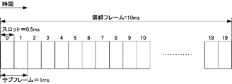
- FIG. 2 is a diagram showing a frame configuration of the present embodiment.
- the horizontal axis is the time domain.
- Downlink and uplink transmissions are organized in radio frames.
- Each single radio frame is 10 ms long.
- Each radio frame is composed of 20 slots.
- Each slot is 0.5 ms long.
- Slots in the radio frame are numbered from 0 to 19.
- a subframe is defined by two consecutive slots.
- Each subframe is 1 ms long.
- the i-th subframe in the radio frame is composed of a (2 ⁇ i) th slot and a (2 ⁇ i + 1) th slot.
- FDD frequency division duplex
- 10 subframes can be used for downlink transmission and 10 subframes can be used for uplink transmission in each 10 ms interval.
- uplink and downlink transmissions are separated in the frequency domain.
- TDD time division duplex
- each of the subframes is reserved for uplink transmission or downlink transmission.
- this embodiment will be described in consideration of the FDD system.
- the present invention is not limited to the FDD system and apparatus, but can be applied to the TDD system and apparatus.
- a subset of downlink subframes in a radio frame can be set as an MBSFN (Multicast / Broadcast over Single Frequency Network) subframe by an upper layer.
- the MBSFN subframe is a subframe reserved for MBSFN.
- a downlink subframe that is not set as an MBSFN subframe is referred to as a non-MBSFN subframe or a unicast subframe.
- the uplink subframe in the radio frame is not used for MBSFN.
- the base station apparatus 3 transmits information (MBSFNsubframeConfigList) indicating a subframe reserved as an MBSFN subframe to the mobile station apparatus 1.
- the mobile station apparatus 1 sets a subset of downlink subframes as MBSFN subframes according to the received MBSFNsubframeConfigList. That is, the MBSFN subframe is a subframe indicated by MBSFNsubframeConfigList.
- the base station apparatus 3 can transmit the PDSCH in the non-MBSFN subframe, and cannot transmit the PMCH. Moreover, the base station apparatus 3 can transmit any one of PDSCH and PMCH in the MBSFN subframe.
- the base station apparatus 3 can transmit a plurality of PDSCHs in a single subframe. In a single subframe, multiple PDSCHs may be frequency multiplexed and / or spatially multiplexed.
- the base station device 3 can transmit a single PMCH using all bands in the subframe in a single subframe.
- Each MBSFN subframe is divided into a non-MBSFN area and an MBSFN area.
- the non-MBSFN region is composed of the first one or two OFDM symbols in the MBSFN subframe.
- the MBSFN region is composed of OFDM symbols that are not used as the non-MBSFN region in the MBSFN subframe.
- the non-MBSFN area is an area that is not reserved for the MBSFN.
- the MBSFN area is an area reserved for MBSFN.
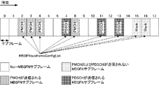
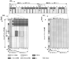
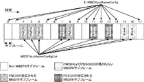
- FIG. 3 is a diagram illustrating an example of setting the MBSFN subframe according to the present embodiment.
- the horizontal axis is the time domain.
- the subframes ⁇ 2, 3, 4, 7, 8, 11, 13, 15, 16 ⁇ are MBSFN subframes, and the remaining subframes are non-MBSFN subframes.
- ⁇ 2, 3, 4, 8 ⁇ subframes are MBSFN subframes used for PMCH transmission.
- subframes ⁇ 7, 11, 13 ⁇ are MBSFN subframes used for PDSCH transmission.
- subframes ⁇ 15, 16 ⁇ are MBSFN subframes in which neither PMCH nor PDSCH is transmitted.
- the subframe MBSFN subframe used for PDSCH transmission and the non-MBSFN subframe used for PDSCH transmission are also referred to as first subframes.
- the MBSFN subframe used for PMCH transmission is also referred to as a second subframe.
- the signal or physical channel transmitted in each subframe is represented by a resource grid.
- the resource grid is defined by a plurality of subcarriers and a plurality of OFDM (Orthogonal-Frequency-Division-Multiplexing) symbols (or SC-FDMA (Single-Carrier-Frequency-Division-Multiple-Access) symbols).
- OFDM Orthogonal-Frequency-Division-Multiplexing
- SC-FDMA Single-Carrier-Frequency-Division-Multiple-Access
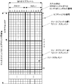
- FIG. 4 is a diagram illustrating a configuration of a first subframe used for PDSCH transmission according to the present embodiment.
- the horizontal axis is the time domain
- the vertical axis is the frequency domain.
- the number of OFDM symbols (SC-FDMA symbols) constituting one slot is seven.
- the resource block is used to express a mapping of resource elements of a certain physical channel (PDSCH or the like).
- resource blocks virtual resource blocks and physical resource blocks are defined.
- a physical channel is first mapped to a virtual resource block. Thereafter, the virtual resource block is mapped to the physical resource block.
- One physical resource block corresponds to one slot in the time domain and corresponds to 180 kHz in the frequency domain. Physical resource blocks are numbered from 0 in the frequency domain.
- one physical resource block is defined by 7 consecutive OFDM symbols (SC-FDMA symbols) in the time domain and 12 consecutive subcarriers in the frequency domain. Therefore, in the first subframe, one physical resource block is composed of (7 ⁇ 12) resource elements.
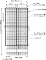
- FIG. 5 is a diagram illustrating a configuration of a second subframe used for PMCH transmission according to the present embodiment.
- the horizontal axis is the time domain
- the vertical axis is the frequency domain.
- the number of OFDM symbols constituting one slot is six.
- one physical resource block is defined by 6 consecutive OFDM symbols in the time domain and 12 consecutive subcarriers in the frequency domain. Therefore, in the second subframe, one physical resource block is composed of (6 ⁇ 12) resource elements.
- the guard interval of the OFDM symbol in the MBSFN area is longer than the guard interval of the OFDM symbol in the non-MBSFN area.
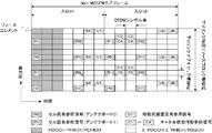
- FIG. 6 is a diagram illustrating an example of an arrangement of physical downlink channels according to the present embodiment.
- the horizontal axis is the time domain, and the vertical axis is the frequency domain.
- the PCFICH is mapped to the 0th (first) OFDM symbol in the nonMBSFN subframe or the MBSFN subframe.
- PCFICH is mapped to four resource element groups distributed in the frequency domain.
- the resource element group is composed of a plurality of resource elements that are continuous in the frequency domain.
- PHICH is mapped to the 0th (first) OFDM symbol in the non-MBSFN subframe or MBSFN subframe.
- One PHICH is mapped to three resource element groups distributed in the frequency domain.
- the base station apparatus 3 can code-multiplex several PHICH on the same resource element.
- PDCCH is mapped to the 0th, 0th and 1st or 0th to 2nd OFDM symbols in the subframe in the non-MBSFN subframe.
- the PDCCH is mapped to the 0th or 0th and 1st OFDM symbols in the subframe in the MBSFN subframe.
- the PDCCH is mapped avoiding the resource elements to which the PCFICH and PHICH are mapped.
- the mobile station apparatus 1 recognizes the OFDM symbol to which the PDCCH is mapped based on the information received by PCFICH. Further, the base station apparatus 3 can time-multiplex and frequency-multiplex a plurality of PDCCHs in a single subframe.
- the base station apparatus 3 can frequency multiplex, time multiplex and / or spatially multiplex a plurality of PDSCHs in a single subframe.
- the E-PDCCH is mapped to an OFDM symbol to which the PDCCH in the nonMBSFN subframe or MBSFN subframe is not mapped.
- E-PDCCH is frequency-multiplexed and time-multiplexed with E-PHICH.
- the E-PDCCH is time-multiplexed with the PDSCH.
- the base station apparatus 3 can frequency multiplex, time multiplex and / or spatially multiplex a plurality of E-PDCCHs within a single subframe.
- PBCH is transmitted in the 0th subframe in each radio frame in the time domain.
- the PBCH is transmitted using OFDM symbols from the 0th to the 3rd in the second slot.
- PBCH is transmitted on 72 subcarriers in the center of the downlink of the cell in the frequency domain.
- the base station apparatus 3 does not transmit PMCH in a subframe in which a synchronization signal and / or PBCH is transmitted.
- Base station apparatus 3 does not reserve a subframe in which a synchronization signal and / or PBCH is transmitted as an MBSFN subframe. That is, the subframe in which the synchronization signal and / or PBCH is transmitted is a non-MBSFN subframe.
- FIG. 7 is a diagram illustrating an example of downlink reference signal mapping in a non-MBSFN subframe used for PDSCH transmission according to the present embodiment.
- the horizontal axis is the time domain, and the vertical axis is the frequency domain.
- FIG. 7 shows only physical resource blocks having the same number in the non-MBSFN subframe.
- a square to which U6 is attached is a resource element used for transmitting the mobile station apparatus specific reference signal of the antenna port 6.
- Resource elements used for CRS transmission are determined based on a physical layer cell identifier (physical-layer cell identity: PCI, Cell ID).
- the resource element used for transmission of CSI-RS in the physical resource block is set by the base station apparatus 3.
- the base station apparatus 3 transmits to the mobile station apparatus 1 information related to CSI-RS settings indicating periodically set downlink subframes, resource elements used for CSI-RS transmission, and the like.
- FIG. 8 is a diagram illustrating an example of mapping of downlink reference signals in the MBSFN subframe used for PMCH transmission according to the present embodiment.
- the horizontal axis is the time domain, and the vertical axis is the frequency domain.
- FIG. 8 shows only physical resource blocks having the same number in the MBSFN subframe.
- a square with M7 is a resource element used for transmitting the MBSFN reference signal of the antenna port 7.
- FIG. 9 is a diagram illustrating an example of mapping of the downlink reference signal in the MBSFN subframe used for PDSCH transmission according to the present embodiment.
- the horizontal axis is the time domain, and the vertical axis is the frequency domain.
- FIG. 9 shows only physical resource blocks having the same number in the MBSFN subframe.
- a square to which U6 is attached is a resource element used for transmitting the mobile station apparatus specific reference signal of the antenna port 6.
- the uplink HARQ in this embodiment is a synchronous HARQ.
- the mobile station apparatus includes one HARQ entity.
- the HARQ entity manages 8 parallel HARQ.
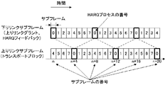
- FIG. 10 is a diagram illustrating an example of synchronous HARQ according to the present embodiment.
- the horizontal axis is the time domain.
- the HARQ process is associated with an uplink or downlink subframe.
- a single downlink or uplink subframe is associated with a single HARQ process.
- the corresponding HARQ process numbers are shifted by 4 in the downlink and uplink subframes.
- the base station apparatus 3 transmits downlink control information and / or HARQ indicator corresponding to the HARQ process number 0 using the downlink subframe n. Based on the downlink control information and / or the HARQ indicator, the mobile station apparatus 1 transmits a transport block corresponding to the 0th HARQ process using the uplink subframe n + 4.
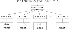
- FIG. 11 is a diagram for explaining an example of the operation of the HARQ entity of the present embodiment.
- the HARQ entity manages HARQ process 0 to HARQ process 7.
- the HARQ entity outputs the input downlink control information, the HARQ indicator, and the transport block to an appropriate HARQ entity.
- Each HARQ process corresponds to a buffer and a state variable. That is, each HARQ process manages a buffer and a state variable.
- the HARQ process stores downlink control information and transport blocks in the buffer.
- the HARQ process sets ACK or NACK in the state variable.
- the HARQ entity When downlink control information for the HARQ process is received and the downlink control information indicates an initial transmission of the transport block, or when downlink control information for the HARQ process is received and stored in the buffer of the identified HARQ process If the transport block is not stored, the HARQ entity obtains the transport block to send, sends the transport block, downlink control information, HARQ indicator to the identified HARQ process, and sends it to the identified HARQ process. Request initial transmission.
- the downlink control information for the HARQ process If the downlink control information for the HARQ process is received, the downlink control information indicates a retransmission of the transport block, and the transport block is stored in the buffer of the identified HARQ process, the HARQ entity Downlink control information and HARQ indicator are sent to the specified HARQ process, and an adaptive retransmission (adaptive retransmission) is requested to the specified HARQ process.
- the HARQ entity sends a HARQ indicator to the identified HARQ process and requests the identified HARQ process for non-adaptive retransmission.
- the HARQ process sets the value of the HARQ indicator (ACK or NACK) in the state variable.
- the HARQ process performs the following operations depending on whether the HARQ entity requests initial transmission, adaptive retransmission, or non-adaptive retransmission.
- the mobile station apparatus 1 acquires a modulation symbol from a PDCCH or E-PDCCH resource element candidate, and attempts to decode downlink control information. Further, the mobile station apparatus 1 generates a CRC code using the decoded downlink control information, and scrambles the generated CRC code using the RNTI assigned to the base station apparatus 3. The mobile station device 1 compares the CRC code generated by itself with the decoded CRC code. When the CRC code generated by itself matches the decoded CRC code, the mobile station device 1 regards that the downlink control information has been successfully decoded and passes the downlink control information to the HARQ entity. When the CRC code generated by itself does not match the decoded CRC code, the mobile station device 1 considers that decoding of the downlink control information has failed.
- FIG. 13 is a flow showing the HARQ indicator encoding method of this embodiment.
- ACK is expressed by ⁇ 1>.
- NACK is expressed by ⁇ 0>.
- the base station apparatus 3 generates a 3-bit sequence ⁇ 0, 0, 0> by encoding NACK ⁇ 0>.
- the base station device 3 generates a 3-bit sequence ⁇ 1, 1, 1> by encoding ACK ⁇ 1> (step S1300).
- the mobile station apparatus 1 transmits a transport block to the base station apparatus 3 using PUSCH and receives an HARQ indicator for transmission of the transport block using E-PHICH is an MBSFN subframe.
- ACK is set to a state variable managed by the HARQ process corresponding to the transport block when the HARQ indicator for the transmission of the transport block is received. That is, the mobile station apparatus 1 does not have to perform E-PHICH reception processing when the HARQ indicator for transmission of the transport block is received using the E-PHICH in the MBSFN subframe.
- the mobile station apparatus 1 sets the HARQ indicator to the HARQ even if the E-PHICH reception process is performed. You may discard it without passing it to the entity.
- the mobile station apparatus 1 when the mobile station apparatus 1 receives the HARQ indicator for transmission of the transport block using the E-PHICH, when the MBSFN subframe indicated by the information is received, the mobile block apparatus 1 The HARQ indicator for the transmission of is received using E-PHICH.
- ACK is set to a state variable managed by the HARQ process corresponding to the transport block.
- the mobile station apparatus 1 can receive the E-PHICH in the MBSFN subframe that is reused for transmitting the PDSCH.
- the mobile station apparatus 1 can determine whether or not the E-PHICH has been correctly decoded in each of the subframes. Also, by this, when the mobile station apparatus 1 fails to decode the E-PHICH transmitted by the base station apparatus 3, or when the base station apparatus 3 transmits E-PHICH, the MBSFN subframe that transmits the PMCH When the E-PHICH cannot be transmitted, the mobile station apparatus 1 considers that the sequence has failed to be decoded, and retransmits the erroneous transport block to pass the ACK to the HARQ entity. Can be avoided.
- the receiving unit 105 separates, demodulates, and decodes the received signal received from the base station apparatus 3 via the transmission / reception antenna 109 according to the control signal input from the control unit 103, and sends the decoded information to the upper layer processing unit 101. Output.
- the demodulating unit 1053 multiplies the PHICH by a corresponding code and synthesizes the signal, demodulates the synthesized signal using a BPSK (Binary Phase Shift Shift Keying) modulation method, and outputs the demodulated signal to the decoding unit 1051.
- Decoding section 1051 decodes the PHICH addressed to the own apparatus, and outputs the decoded HARQ indicator to higher layer processing section 101.
- Demodulation section 1053 demodulates the QPSK modulation scheme for PDCCH and outputs the result to decoding section 1051.
- Decoding section 1051 attempts blind decoding of PDCCH, and when blind decoding is successful, decodes downlink control information and outputs RNTI included in downlink control information to higher layer processing section 101.
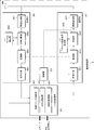
- the upper layer processing unit 301 includes a medium access control (MAC: Medium Access Control) layer, a packet data integration protocol (Packet Data Convergence Protocol: PDCP) layer, a radio link control (Radio Link Control: RLC) layer, a radio resource control (Radio). Resource (Control: RRC) layer processing. Further, upper layer processing section 301 generates control information for controlling receiving section 305 and transmitting section 307 and outputs the control information to control section 303.
- MAC Medium Access Control
- PDCP Packet Data Convergence Protocol
- RLC Radio Link Control
- Radio Radio Resource
- the radio resource control unit 3011 provided in the upper layer processing unit 301 generates downlink data (transport block), RRC signal, MAC CE (Control Element) arranged in the downlink PDSCH, or acquires it from the upper node. And output to the transmission unit 307. Further, the radio resource control unit 3011 manages various setting information of each mobile station apparatus 1. For example, the radio resource control unit 3011 performs management of RNTI and physical channel settings.
- the wireless receiver 3057 removes a portion corresponding to a guard interval (Guard Interval: GI) from the converted digital signal.
- the radio reception unit 3057 performs fast Fourier transform (FFT) on the signal from which the guard interval is removed, extracts a frequency domain signal, and outputs the signal to the demultiplexing unit 3055.
- FFT fast Fourier transform
- the decoding unit 3051 encodes the demodulated PUCCH and PUSCH encoded bits in a predetermined encoding method in advance or the mobile station apparatus 1 previously notified to the mobile station apparatus 1 using an uplink grant. Decoding is performed at a rate, and the decoded uplink data and uplink control information are output to the upper layer processing section 101. When PUSCH is retransmitted, decoding section 3051 performs decoding using the encoded bits held in the HARQ buffer input from higher layer processing section 301 and the demodulated encoded bits.
- Channel measurement section 309 measures an estimated channel value, channel quality, and the like from the uplink reference signal input from demultiplexing section 3055 and outputs the result to demultiplexing section 3055 and higher layer processing section 301.
- the transmission unit 307 generates a downlink reference signal according to the control signal input from the control unit 303, encodes and modulates the HARQ indicator, downlink control information, and downlink data input from the higher layer processing unit 301. Then, the PHICH, PDCCH, PDSCH, and downlink reference signal are multiplexed, and the signal is transmitted to the mobile station device 1 via the transmission / reception antenna 309.
- the encoding unit 3071 is a predetermined encoding method such as block encoding, convolutional encoding, turbo encoding, and the like for the HARQ indicator, downlink control information, and downlink data input from the higher layer processing unit 301 Or is encoded using the encoding method determined by the radio resource control unit 3011.
- the modulation unit 3073 modulates the coded bits input from the coding unit 3071 with a modulation scheme determined in advance by the radio resource control unit 3011 such as BPSK, QPSK, 16QAM, and 64QAM.
- the downlink reference signal generation unit 3079 obtains a sequence known by the mobile station device 1 as a downlink reference signal, which is obtained by a predetermined rule based on a physical layer cell identifier (PCI) for identifying the base station device 3 or the like. Generate.
- the multiplexing unit 3075 multiplexes the modulated modulation symbol of each channel and the generated downlink reference signal. That is, multiplexing section 3075 arranges the modulated modulation symbol of each channel and the generated downlink reference signal in the resource element.
- the wireless transmission unit 3077 performs inverse fast Fourier transform (Inverse Fast Fourier Transform: IFFT) on the multiplexed modulation symbols and the like, performs modulation in the OFDM scheme, adds a guard interval to the OFDM symbol that has been OFDM-modulated, and baseband
- IFFT inverse Fast Fourier Transform
- the baseband digital signal is converted to an analog signal, the in-phase and quadrature components of the intermediate frequency are generated from the analog signal, the extra frequency components for the intermediate frequency band are removed, and the intermediate-frequency signal is generated. Is converted to a high-frequency signal (up-conversion: up convert), an extra frequency component is removed, power is amplified, and output to the transmission / reception antenna 309 for transmission.
- a program that operates in the base station apparatus 3 and the mobile station apparatus 1 related to the present invention is a program (computer functions as a computer) that controls a CPU (Central Processing Unit) so as to realize the functions of the above-described embodiments related to the present invention.
- Program Information handled by these devices is temporarily stored in RAM (Random Access Memory) during the processing, and then stored in various ROMs such as Flash ROM (Read Only Memory) and HDD (Hard Disk Drive). Reading, correction, and writing are performed by the CPU as necessary.
- the program for realizing the control function may be recorded on a computer-readable recording medium, and the program recorded on the recording medium may be read by the computer system and executed.
- the “computer-readable recording medium” is a medium that dynamically holds a program for a short time, such as a communication line when transmitting a program via a network such as the Internet or a communication line such as a telephone line,
- a volatile memory inside a computer system serving as a server or a client may be included and a program that holds a program for a certain time.
- the program may be a program for realizing a part of the functions described above, and may be a program capable of realizing the functions described above in combination with a program already recorded in a computer system.
- a part or all of the mobile station device 1 and the base station device 3 in the above-described embodiment may be realized as an LSI that is typically an integrated circuit, or may be realized as a chip set.
- Each functional block of the mobile station device 1 and the base station device 3 may be individually chipped, or a part or all of them may be integrated into a chip.
- the method of circuit integration is not limited to LSI, and may be realized by a dedicated circuit or a general-purpose processor.
- an integrated circuit based on the technology can also be used.
- the mobile station apparatus of the present invention is a mobile station apparatus that communicates with a base station apparatus using an MBSFNF (Multicast / Broadcast over Single Frequency Network) subframe and a non-MBSFN subframe, and uses a physical uplink shared channel.
- the transport block is transmitted to the base station apparatus, and when the HARQ feedback for the transmission of the transport block is received using the extended physical HARQ indicator channel is an MBSFN subframe, When receiving the HARQ feedback for transmission, ACK (acknowledgement) is set to a state variable managed by the HARQ process corresponding to the transport block.
- MBSFNF Multicast / Broadcast over Single Frequency Network
- the specific MBSFN subframe is an MBSFN subframe in which the mobile station apparatus has not detected a mobile station apparatus specific reference signal.
- the mobile station apparatus receives information indicating a subframe reserved as the MBSFN subframe.
- the transport block corresponds to the corresponding HAR
- a state variable managed by the process is set to ACK (acknowledgement) or NACK (negative-acknowledgement) indicated by the HARQ feedback received using the extended physical HARQ indicator channel, and the transmission block is transmitted. If the extended physical HARQ indicator channel used for transmission of HARQ feedback is not detected, ACK (acknowledgement) is set to a state variable managed by the HARQ process corresponding to the transport block.
- the present invention receives information indicating whether or not HARQ feedback for transmission of a transport block must be received using an extended physical HARQ indicator channel in the above mobile station apparatus. .
- the HARQ feedback for transmission of the transport block in the subframe that is four times after the subframe that transmitted the transport block is the extended physical Receive using the HARQ indicator channel.
- the radio communication method of the present invention is a radio communication method used for a mobile station apparatus that communicates with a base station apparatus using an MBSFN (Multicast / Broadcast (overcast) single (Frequency) Network) subframe and a non-MBSFN subframe.
- MBSFN Multicast / Broadcast (overcast) single (Frequency) Network
- a transport block is transmitted to the base station apparatus using a physical uplink shared channel and HARQ feedback for transmission of the transport block is received using an extended physical HARQ indicator channel, a specific MBSFN If it is a subframe, when receiving the HARQ feedback for transmission of the transport block, an ACK (acknowledgement) is set to a state variable managed by the HARQ process corresponding to the transport block.
- MBSFN Multicast / Broadcast (overcast) single (Frequency) Network
- the radio communication method of the present invention receives HARQ feedback for transmission of a transport block from a base station apparatus using either or either of a physical HARQ indicator channel and an extended physical HARQ indicator channel.
- a wireless communication method used in a mobile station apparatus wherein information indicating a subframe reserved for transmission of the HARQ feedback using the extended physical HARQ indicator channel is received, and a physical uplink shared channel
- the transport block is transmitted to the base station apparatus using the information, and when the HARQ feedback for the transport block transmission is received using the extended physical HARQ indicator channel, the information indicates. If a subframe excluding subframes, when receiving the HARQ feedback for the transmission of the transport block, and sets the ACK (acknowledgment) to a state variable HARQ process the transport block corresponding managed.
- HARQ feedback for transmission of a transport block is received from a base station apparatus using either or both of a physical HARQ indicator channel and an extended physical HARQ indicator channel.
- a wireless communication method used in a mobile station apparatus, wherein the transport block is transmitted to the base station apparatus using a physical uplink shared channel, and the identifier corresponding to the extended physical HARQ indicator channel is used.
- an attempt is made to detect an extended physical HARQ indicator channel and the extended physical HARQ indicator channel used for transmission of the HARQ feedback for transmission of the transport block is detected, Set the state variable managed by the HARQ process corresponding to the block to ACK (acknowledgement) or NACK (negative-acknowledgement) indicated by the HARQ feedback received using the extended physical HARQ indicator channel, and the transport If the extended physical HARQ indicator channel used for transmission of the HARQ feedback for transmission of a block is not detected, an ACK (acknowledgement) is set in a state variable managed by the corresponding HARQ process of the transport block. .
- the integrated circuit of the present invention is mounted on a mobile station apparatus that communicates with a base station apparatus using an MBSFN (Multicast / Broadcast (overcast) single (Frequency) Network) subframe and a non-MBSFN subframe.
- the physical HARQ indicator channel is an MBSFN subframe
- an ACK is sent to the state variable managed by the corresponding HARQ process. (Ackn owledgement) is set to the mobile station apparatus.
- the integrated circuit of the present invention is mounted on a mobile station apparatus that communicates with a base station apparatus using an MBSFN (Multicast / Broadcast (overcast) over Single (Frequency) Network) subframe and a non-MBSFN subframe.
- State variable managed by the corresponding HARQ process when receiving the HARQ feedback for transmission of the transport block, when receiving using the physical HARQ indicator channel is a specific MBSFN subframe AC To exhibit a function to set the (acknowledgment), to the mobile station apparatus.
- the integrated circuit of the present invention is a mobile that receives HARQ feedback for transmission of a transport block from a base station apparatus using both or either of a physical HARQ indicator channel and an extended physical HARQ indicator channel.
- the time to receive using the dedicator channel is a subframe excluding the subframe indicated by the information, the HARQ process to which the transport block corresponds when receiving the HARQ feedback for transmission of the transport block
- the mobile station apparatus has a function of setting ACK (acknowledgement) in a state variable managed by the mobile station apparatus.
- the mobile station apparatus has a function of setting ACK (acknowledgement) in a state variable to be managed.
- the base station apparatus of the present invention communicates with a mobile station apparatus using an MBSFN (Multicast / Broadcast over Single Frequency Network) subframe and a non-MBSFN subframe, and a physical HARQ indicator channel and an extended physical
- MBSFN Multicast / Broadcast over Single Frequency Network
- a physical HARQ indicator channel and an extended physical A base station apparatus that transmits HARQ feedback for transmission of a transport block to the mobile station apparatus using both or one of the HARQ indicator channels, wherein the extended physical HARQ indicator in the MBSFN subframe Information indicating a subframe reserved for transmission of the HARQ feedback using a channel is transmitted.
- the base station apparatus of the present invention transmits HARQ feedback for transmission of the transport block to the mobile station apparatus using either or both of the physical HARQ indicator channel and the extended physical HARQ indicator channel.
- the base station apparatus transmits information indicating a subframe reserved for transmission of the HARQ feedback using the extended physical HARQ indicator channel to the mobile station apparatus.
- the mobile station transmits information indicating whether HARQ feedback for transmission of a transport block should be received using an extended physical HARQ indicator channel. Send to station device.
- the HARQ feedback for transmission of the transport block is the extended physical It transmits to the said mobile station apparatus using a HARQ indicator channel.
- the wireless communication method of the present invention communicates with a mobile station apparatus using an MBSFN (Multicast / Broadcast over Single Frequency Network) subframe and a non-MBSFN subframe, and a physical HARQ indicator channel and an extended physical
- MBSFN Multicast / Broadcast over Single Frequency Network
- the MBSFN subframe includes: Information indicating a subframe reserved for transmission of the HARQ feedback using the extended physical HARQ indicator channel is transmitted.
- the radio communication method of the present invention transmits HARQ feedback for transmission of a transport block to a mobile station apparatus using both or either of a physical HARQ indicator channel and an extended physical HARQ indicator channel.
- a radio communication method used in a base station apparatus, wherein information indicating a subframe reserved for transmission of the HARQ feedback using the extended physical HARQ indicator channel is transmitted to the mobile station apparatus.
- the integrated circuit of the present invention uses a physical HARQ indicator channel and / or an extended physical HARQ indicator channel, or a base that transmits HARQ feedback for transmission of a transport block to a mobile station apparatus.
- An integrated circuit that is implemented in a station device to cause the base station device to function, and indicates a subframe reserved for transmission of the HARQ feedback using the extended physical HARQ indicator channel
- the base station apparatus has a function of transmitting information to be transmitted to the mobile station apparatus.
Landscapes
- Engineering & Computer Science (AREA)
- Signal Processing (AREA)
- Computer Networks & Wireless Communication (AREA)
- Multimedia (AREA)
- Mobile Radio Communication Systems (AREA)
- Detection And Prevention Of Errors In Transmission (AREA)
Priority Applications (3)
| Application Number | Priority Date | Filing Date | Title |
|---|---|---|---|
| CN201380014015.7A CN104170509B (zh) | 2012-03-14 | 2013-03-11 | 移动站装置、基站装置、无线通信方法 |
| US14/384,961 US9320033B2 (en) | 2012-03-14 | 2013-03-11 | Mobile station device, base station device, wireless communication method, and integrated circuit |
| EP13760662.0A EP2827672B1 (en) | 2012-03-14 | 2013-03-11 | Mobile station device, base station device, wireless communication method, and collection circuit |
Applications Claiming Priority (2)
| Application Number | Priority Date | Filing Date | Title |
|---|---|---|---|
| JP2012056894A JP5941305B2 (ja) | 2012-03-14 | 2012-03-14 | 移動局装置、基地局装置、無線通信システム、無線通信方法および集積回路 |
| JP2012-056894 | 2012-03-14 |
Publications (1)
| Publication Number | Publication Date |
|---|---|
| WO2013137164A1 true WO2013137164A1 (ja) | 2013-09-19 |
Family
ID=49161073
Family Applications (1)
| Application Number | Title | Priority Date | Filing Date |
|---|---|---|---|
| PCT/JP2013/056576 Ceased WO2013137164A1 (ja) | 2012-03-14 | 2013-03-11 | 移動局装置、基地局装置、無線通信方法および集積回路 |
Country Status (5)
| Country | Link |
|---|---|
| US (1) | US9320033B2 (enExample) |
| EP (1) | EP2827672B1 (enExample) |
| JP (1) | JP5941305B2 (enExample) |
| CN (1) | CN104170509B (enExample) |
| WO (1) | WO2013137164A1 (enExample) |
Cited By (1)
| Publication number | Priority date | Publication date | Assignee | Title |
|---|---|---|---|---|
| EP3113561A4 (en) * | 2014-02-26 | 2017-10-11 | Sharp Kabushiki Kaisha | Terminal device, integrated circuit, and wireless communication method |
Families Citing this family (17)
| Publication number | Priority date | Publication date | Assignee | Title |
|---|---|---|---|---|
| CN103428713B (zh) * | 2012-05-15 | 2016-11-02 | 上海贝尔股份有限公司 | 物理下行链路控制信道的检测方法与装置 |
| CN104144030B (zh) * | 2013-05-09 | 2019-05-10 | 中兴通讯股份有限公司 | 数据发送、接收方法、数据发送及接收端 |
| CN106160974B (zh) * | 2015-04-08 | 2020-11-24 | 中兴通讯股份有限公司 | 一种实现信道传输的方法及基站 |
| CN106576249B (zh) * | 2015-07-29 | 2019-11-26 | 华为技术有限公司 | 反馈信息的发送装置、接收装置及方法 |
| JPWO2017130800A1 (ja) * | 2016-01-26 | 2018-11-15 | 株式会社Nttドコモ | 基地局及び送信方法 |
| US11319107B2 (en) * | 2016-03-07 | 2022-05-03 | Qualcomm Incorporated | Synchronization for standalone LTE broadcast |
| EP3439395B1 (en) * | 2016-03-31 | 2021-10-27 | Sony Group Corporation | Terminal device, base station and communication method |
| JP2019149591A (ja) * | 2016-07-14 | 2019-09-05 | シャープ株式会社 | 端末装置、基地局装置、通信方法、および、集積回路 |
| CN107634924B (zh) * | 2016-07-18 | 2020-08-11 | 中兴通讯股份有限公司 | 同步信号的发送、接收方法及装置、传输系统 |
| EP3324549B1 (en) * | 2016-11-18 | 2021-02-24 | Nxp B.V. | Method and apparatus for inductive communication |
| CN110050452B (zh) * | 2016-12-28 | 2022-03-01 | 夏普株式会社 | 基站装置、终端装置、通信方法及集成电路 |
| JP2020107918A (ja) * | 2017-04-21 | 2020-07-09 | シャープ株式会社 | 端末装置、基地局装置、通信方法、および、集積回路 |
| CN108809525A (zh) * | 2017-05-04 | 2018-11-13 | 株式会社Ntt都科摩 | Harq-ack反馈方法、harq-ack提取方法、基站和用户设备 |
| IT201800000832A1 (it) * | 2018-01-12 | 2019-07-12 | Inst Rundfunktechnik Gmbh | Sender und/oder empfänger zum senden bzw. empfangen von rundfunkinformationssignalen |
| CN111092696B (zh) * | 2019-08-02 | 2024-08-02 | 中兴通讯股份有限公司 | 一种无线通信的传输方法、终端设备及存储介质 |
| US20230133369A1 (en) * | 2020-03-27 | 2023-05-04 | Ntt Docomo, Inc. | Terminal, radio communication method, and base station |
| US12562845B2 (en) | 2021-01-22 | 2026-02-24 | Beijing Xiaomi Mobile Software Co., Ltd. | Communication method, communication apparatus, and storage medium |
Citations (1)
| Publication number | Priority date | Publication date | Assignee | Title |
|---|---|---|---|---|
| WO2010016274A1 (ja) * | 2008-08-08 | 2010-02-11 | パナソニック株式会社 | 無線通信基地局装置、無線通信端末装置およびチャネル割当方法 |
Family Cites Families (6)
| Publication number | Priority date | Publication date | Assignee | Title |
|---|---|---|---|---|
| KR101454482B1 (ko) * | 2007-05-17 | 2014-10-27 | 삼성전자주식회사 | 무선 통신 시스템에서 공통 제어 정보 송수신 시스템 및방법 |
| JP5928873B2 (ja) * | 2009-02-03 | 2016-06-01 | ノキア ソリューションズ アンド ネットワークス オサケユキチュア | 装置、方法及び製品 |
| US9374148B2 (en) * | 2009-11-17 | 2016-06-21 | Qualcomm Incorporated | Subframe dependent transmission mode in LTE-advanced |
| US8670410B2 (en) * | 2010-09-17 | 2014-03-11 | Qualcomm Incorporated | Uplink control channel resource mapping for carrier aggregation |
| US20130201926A1 (en) * | 2011-08-11 | 2013-08-08 | Samsung Electronics Co., Ltd. | System and method for physical downlink control and hybrid-arq indicator channels in lte-a systems |
| US8842628B2 (en) * | 2011-09-12 | 2014-09-23 | Blackberry Limited | Enhanced PDCCH with transmit diversity in LTE systems |
-
2012
- 2012-03-14 JP JP2012056894A patent/JP5941305B2/ja active Active
-
2013
- 2013-03-11 US US14/384,961 patent/US9320033B2/en active Active
- 2013-03-11 WO PCT/JP2013/056576 patent/WO2013137164A1/ja not_active Ceased
- 2013-03-11 CN CN201380014015.7A patent/CN104170509B/zh active Active
- 2013-03-11 EP EP13760662.0A patent/EP2827672B1/en active Active
Patent Citations (1)
| Publication number | Priority date | Publication date | Assignee | Title |
|---|---|---|---|---|
| WO2010016274A1 (ja) * | 2008-08-08 | 2010-02-11 | パナソニック株式会社 | 無線通信基地局装置、無線通信端末装置およびチャネル割当方法 |
Non-Patent Citations (6)
| Title |
|---|
| "Views on Enhanced PHICH", 3GPP TSG RANI #67, 14 November 2011 (2011-11-14) |
| "Way Forward on downlink Control channel enhancements by UE-specific RS", 3GPP TSG RANI #66B IS, 10 October 2011 (2011-10-10) |
| INTERDIGITAL COMMUNICATIONS: "Considerations on ePHICH in Rel-11", 3GPP TSG RAN WG1 MEETING #68, February 2012 (2012-02-01), XP050599611 * |
| LG ELECTRONICS: "Aspects on DL and UL Control Channels for HARQ with Enhanced PDCCH", 3GPP TSG RAN WG1 MEETING #67, 14 November 2011 (2011-11-14), pages 1 - 4, XP050562275 * |
| SAMSUNG: "PHICH structure in MBSFN subframes", 3GPP TSG RAN WG1 MEETING #50BIS, 12 October 2007 (2007-10-12), pages 1 - 2, XP050108245 * |
| See also references of EP2827672A4 |
Cited By (1)
| Publication number | Priority date | Publication date | Assignee | Title |
|---|---|---|---|---|
| EP3113561A4 (en) * | 2014-02-26 | 2017-10-11 | Sharp Kabushiki Kaisha | Terminal device, integrated circuit, and wireless communication method |
Also Published As
| Publication number | Publication date |
|---|---|
| EP2827672A1 (en) | 2015-01-21 |
| JP5941305B2 (ja) | 2016-06-29 |
| EP2827672B1 (en) | 2022-10-26 |
| US20150029929A1 (en) | 2015-01-29 |
| CN104170509B (zh) | 2018-03-23 |
| EP2827672A4 (en) | 2016-01-20 |
| CN104170509A (zh) | 2014-11-26 |
| US9320033B2 (en) | 2016-04-19 |
| JP2013192037A (ja) | 2013-09-26 |
Similar Documents
| Publication | Publication Date | Title |
|---|---|---|
| JP5941305B2 (ja) | 移動局装置、基地局装置、無線通信システム、無線通信方法および集積回路 | |
| JP6287850B2 (ja) | 端末装置、集積回路、無線通信方法、および、基地局装置 | |
| JP5856810B2 (ja) | 基地局装置、移動局装置、無線通信方法、無線通信システムおよび集積回路 | |
| JP6380956B2 (ja) | 端末装置、基地局装置、集積回路、および、通信方法 | |
| EP3500018B1 (en) | Terminal device, base station device, and communication method | |
| JP6452048B2 (ja) | 端末装置、基地局装置、通信方法、および、集積回路 | |
| JP6240976B2 (ja) | 端末装置、基地局装置、集積回路、および、通信方法 | |
| JP6041295B2 (ja) | 端末装置、基地局装置、および無線通信方法 | |
| JP6179009B2 (ja) | 端末装置、基地局装置、無線通信方法、および集積回路 | |
| WO2014073671A1 (ja) | 端末装置、通信方法および集積回路 | |
| JP6417599B2 (ja) | 端末装置、無線通信方法、および集積回路 | |
| WO2014115781A1 (ja) | 端末装置、集積回路、無線通信方法および基地局装置 | |
| WO2014003104A1 (ja) | 基地局装置、移動局装置、無線通信方法、集積回路、および無線通信システム | |
| JPWO2015045731A1 (ja) | 端末装置、基地局装置、集積回路、および、通信方法 | |
| WO2014136789A1 (ja) | 基地局装置、端末装置、集積回路および無線通信方法 | |
| CN105075374B (zh) | 终端装置、基站装置、集成电路以及无线通信方法 | |
| JP6034946B2 (ja) | 基地局装置、移動局装置、無線通信方法、無線通信システムおよび集積回路 | |
| WO2011155344A1 (ja) | 無線通信システム、基地局装置、移動局装置、無線通信方法および集積回路 | |
| WO2014136790A1 (ja) | 端末装置、集積回路、無線通信方法、および基地局装置 |
Legal Events
| Date | Code | Title | Description |
|---|---|---|---|
| 121 | Ep: the epo has been informed by wipo that ep was designated in this application |
Ref document number: 13760662 Country of ref document: EP Kind code of ref document: A1 |
|
| WWE | Wipo information: entry into national phase |
Ref document number: 14384961 Country of ref document: US |
|
| NENP | Non-entry into the national phase |
Ref country code: DE |
|
| WWE | Wipo information: entry into national phase |
Ref document number: 2013760662 Country of ref document: EP |