WO2013137062A1 - 塗布具 - Google Patents
塗布具 Download PDFInfo
- Publication number
- WO2013137062A1 WO2013137062A1 PCT/JP2013/055983 JP2013055983W WO2013137062A1 WO 2013137062 A1 WO2013137062 A1 WO 2013137062A1 JP 2013055983 W JP2013055983 W JP 2013055983W WO 2013137062 A1 WO2013137062 A1 WO 2013137062A1
- Authority
- WO
- WIPO (PCT)
- Prior art keywords
- sheath
- applicator
- gas
- nozzle
- abdominal cavity
- Prior art date
Links
Images


Classifications
-
- A—HUMAN NECESSITIES
- A61—MEDICAL OR VETERINARY SCIENCE; HYGIENE
- A61B—DIAGNOSIS; SURGERY; IDENTIFICATION
- A61B17/00—Surgical instruments, devices or methods, e.g. tourniquets
- A61B17/00491—Surgical glue applicators
-
- A—HUMAN NECESSITIES
- A61—MEDICAL OR VETERINARY SCIENCE; HYGIENE
- A61M—DEVICES FOR INTRODUCING MEDIA INTO, OR ONTO, THE BODY; DEVICES FOR TRANSDUCING BODY MEDIA OR FOR TAKING MEDIA FROM THE BODY; DEVICES FOR PRODUCING OR ENDING SLEEP OR STUPOR
- A61M25/00—Catheters; Hollow probes
- A61M25/01—Introducing, guiding, advancing, emplacing or holding catheters
- A61M25/06—Body-piercing guide needles or the like
- A61M25/0662—Guide tubes
-
- A—HUMAN NECESSITIES
- A61—MEDICAL OR VETERINARY SCIENCE; HYGIENE
- A61B—DIAGNOSIS; SURGERY; IDENTIFICATION
- A61B17/00—Surgical instruments, devices or methods, e.g. tourniquets
- A61B17/34—Trocars; Puncturing needles
- A61B17/3474—Insufflating needles, e.g. Veress needles
-
- A—HUMAN NECESSITIES
- A61—MEDICAL OR VETERINARY SCIENCE; HYGIENE
- A61M—DEVICES FOR INTRODUCING MEDIA INTO, OR ONTO, THE BODY; DEVICES FOR TRANSDUCING BODY MEDIA OR FOR TAKING MEDIA FROM THE BODY; DEVICES FOR PRODUCING OR ENDING SLEEP OR STUPOR
- A61M25/00—Catheters; Hollow probes
- A61M25/0067—Catheters; Hollow probes characterised by the distal end, e.g. tips
- A61M25/0068—Static characteristics of the catheter tip, e.g. shape, atraumatic tip, curved tip or tip structure
- A61M25/007—Side holes, e.g. their profiles or arrangements; Provisions to keep side holes unblocked
-
- A—HUMAN NECESSITIES
- A61—MEDICAL OR VETERINARY SCIENCE; HYGIENE
- A61M—DEVICES FOR INTRODUCING MEDIA INTO, OR ONTO, THE BODY; DEVICES FOR TRANSDUCING BODY MEDIA OR FOR TAKING MEDIA FROM THE BODY; DEVICES FOR PRODUCING OR ENDING SLEEP OR STUPOR
- A61M5/00—Devices for bringing media into the body in a subcutaneous, intra-vascular or intramuscular way; Accessories therefor, e.g. filling or cleaning devices, arm-rests
- A61M5/14—Infusion devices, e.g. infusing by gravity; Blood infusion; Accessories therefor
- A61M5/1407—Infusion of two or more substances
-
- A—HUMAN NECESSITIES
- A61—MEDICAL OR VETERINARY SCIENCE; HYGIENE
- A61M—DEVICES FOR INTRODUCING MEDIA INTO, OR ONTO, THE BODY; DEVICES FOR TRANSDUCING BODY MEDIA OR FOR TAKING MEDIA FROM THE BODY; DEVICES FOR PRODUCING OR ENDING SLEEP OR STUPOR
- A61M5/00—Devices for bringing media into the body in a subcutaneous, intra-vascular or intramuscular way; Accessories therefor, e.g. filling or cleaning devices, arm-rests
- A61M5/14—Infusion devices, e.g. infusing by gravity; Blood infusion; Accessories therefor
- A61M5/142—Pressure infusion, e.g. using pumps
-
- A—HUMAN NECESSITIES
- A61—MEDICAL OR VETERINARY SCIENCE; HYGIENE
- A61B—DIAGNOSIS; SURGERY; IDENTIFICATION
- A61B17/00—Surgical instruments, devices or methods, e.g. tourniquets
- A61B17/00491—Surgical glue applicators
- A61B2017/00495—Surgical glue applicators for two-component glue
-
- A—HUMAN NECESSITIES
- A61—MEDICAL OR VETERINARY SCIENCE; HYGIENE
- A61M—DEVICES FOR INTRODUCING MEDIA INTO, OR ONTO, THE BODY; DEVICES FOR TRANSDUCING BODY MEDIA OR FOR TAKING MEDIA FROM THE BODY; DEVICES FOR PRODUCING OR ENDING SLEEP OR STUPOR
- A61M5/00—Devices for bringing media into the body in a subcutaneous, intra-vascular or intramuscular way; Accessories therefor, e.g. filling or cleaning devices, arm-rests
- A61M2005/006—Devices for bringing media into the body in a subcutaneous, intra-vascular or intramuscular way; Accessories therefor, e.g. filling or cleaning devices, arm-rests for gases, e.g. CO2
-
- A—HUMAN NECESSITIES
- A61—MEDICAL OR VETERINARY SCIENCE; HYGIENE
- A61M—DEVICES FOR INTRODUCING MEDIA INTO, OR ONTO, THE BODY; DEVICES FOR TRANSDUCING BODY MEDIA OR FOR TAKING MEDIA FROM THE BODY; DEVICES FOR PRODUCING OR ENDING SLEEP OR STUPOR
- A61M25/00—Catheters; Hollow probes
- A61M2025/0098—Catheters; Hollow probes having a strain relief at the proximal end, e.g. sleeve
-
- A—HUMAN NECESSITIES
- A61—MEDICAL OR VETERINARY SCIENCE; HYGIENE
- A61M—DEVICES FOR INTRODUCING MEDIA INTO, OR ONTO, THE BODY; DEVICES FOR TRANSDUCING BODY MEDIA OR FOR TAKING MEDIA FROM THE BODY; DEVICES FOR PRODUCING OR ENDING SLEEP OR STUPOR
- A61M25/00—Catheters; Hollow probes
- A61M25/01—Introducing, guiding, advancing, emplacing or holding catheters
- A61M25/06—Body-piercing guide needles or the like
- A61M25/0662—Guide tubes
- A61M2025/0681—Systems with catheter and outer tubing, e.g. sheath, sleeve or guide tube
Definitions
- the present invention relates to an applicator for applying an anti-adhesion material, a biological tissue adhesive or the like to an affected area, and more particularly to an applicator suitably used for laparoscopic surgery.
- the conventional applicator has a configuration in which components that coagulate when mixed, for example, a solution containing thrombin and a solution containing fibrinogen are separated from each other, sent to the vicinity of the affected area, and applied while mixing in the affected area. is there.
- Patent Document 1 there is one having two syringes each containing different types of liquids and a nozzle for mixing and ejecting liquids from the respective syringes (for example, see Patent Document 1).
- the applicator of Patent Document 1 has a long cylindrical nozzle body and a nozzle head provided on the tip side of the nozzle body, and has a flexibility at the tip of the nozzle body.
- the nozzle formed with the bending portion to be bent and the nozzle body are inserted so as to be movable along the longitudinal axis direction, and the shape of the bending portion is corrected by inserting the bending portion. And a sheath for adjusting the direction with respect to.
- a gap is formed between the sheath and the nozzle along the longitudinal axis direction, and when the pneumoperitoneum pressure in the abdominal cavity increases, the gap discharges the gas in the abdominal cavity to the outside of the body through the gap. Functions as an exhaust path.
- two side holes penetrating the wall portion are formed at one position on the circumference closer to the base end side than the distal end opening. These side holes are arranged opposite to each other via the sheath axis at the same circumferential position in the longitudinal axis direction of the sheath. Each side hole functions as an intake for taking in gas in the abdominal cavity.
- gas is injected into the abdominal cavity during treatment using an adhesion prevention material, a biological tissue adhesive, or the like. This gas increases the pressure in the abdominal cavity, but the gas in the abdominal cavity is discharged outside the body through a side hole.
- the abdominal cavity during treatment using an adhesion preventing material, a biological tissue adhesive, or the like is formed by a side hole formed at one position on the proximal side of the distal end opening of the sheath. The pressure rise inside is suppressed.
- An object of the present invention is to provide an applicator that solves the problems based on the above-described conventional technology and can suppress the influence on the pressure in the abdominal cavity regardless of the form of use.
- the present invention provides a long nozzle body to which a gas and a plurality of types of liquids are supplied, and a gas provided to the nozzle body on the tip side and supplied to the nozzle body.
- a nozzle having a nozzle head for ejecting a mixed liquid of seeds, and a sheath through which the nozzle body is inserted so as to be relatively movable along the longitudinal axis direction.
- the plurality of side holes are formed at equal intervals along the circumferential direction of the sheath at each of the plurality of positions along the longitudinal axis direction of the sheath.
- the number of the plurality of side holes formed along the circumferential direction at each of the plurality of positions along the longitudinal axis direction of the sheath is preferably 2 or 3.
- the discharge route of gas in the abdominal cavity to the outside of the body is provided. It becomes plural, the gas in the abdominal cavity can be discharged out of the body regardless of the usage form of the applicator, and the pressure increase in the abdominal cavity can be suppressed.
- FIG. 1 It is a schematic diagram which shows the applicator of embodiment of this invention. It is a typical perspective view which shows the applicator of embodiment of this invention.
- (A) is typical sectional drawing which shows the crushing part of the applicator of embodiment of this invention
- (b) is a typical perspective view which shows the crushing part of the applicator of embodiment of this invention.
- (A) And (b) is a schematic diagram which shows the apparatus used for the measuring method of sliding resistance.
- A) And (b) is a schematic diagram which shows the usage pattern of the applicator of embodiment of this invention
- (c) is a schematic diagram which shows the usage pattern of the conventional applicator.
- FIG. 1 is a schematic view showing an applicator according to an embodiment of the present invention
- FIG. 2 is a schematic perspective view showing an applicator according to an embodiment of the present invention
- FIG. It is typical sectional drawing which shows the crushing part of the applicator of embodiment
- (b) is a typical perspective view which shows the crushing part of the applicator of embodiment of this invention.
- the applicator 10 shown in FIG. 1 is, for example, inserted into the abdominal cavity 72 during laparoscopic surgery, and is formed by mixing two kinds of liquids having different liquid compositions, or an adhesion preventing material or biological tissue adhesive. This is for applying the material to the affected part such as the organ or the abdominal wall 70.
- the applicator 10 is inserted into the abdominal cavity 72 through a trocar 50 previously placed on the abdominal wall 70.
- the configuration of the trocar 50 is not particularly limited, and various known ones used for laparoscopic surgery can be used.
- the trocar tube disclosed in FIG. 1 of JP-A-2009-226189 Can also be used.
- Such a trocar 50 is shown in FIG.
- the trocar 50 communicates with a tubular main body 52 and is provided with a hollow hub 54.
- the hub 54 has a diameter larger than that of the main body 52 and communicates with the main body 52.
- the main body 52 is for inserting the applicator 10 described in detail later.
- a gap 53 is generated between the main body 52 and the sheath 14 of the applicator 10.
- the main body 52 of the trocar 50 may have its tip opening inclined with respect to the axis of the main body 52. Thereby, the insertion operation into the abdominal cavity 72 of the trocar 50 can be performed easily.
- the hub 54 is connected to the gas supply unit 60 through a tube 62.
- the gas supply unit 60 includes a gas cylinder (not shown) filled with aseptic gas Gv at a high pressure. Aseptic gas Gv passes through the tube 62, the hub 54, and the main body 52 in order by the gas supply unit 60 and is supplied into the abdominal cavity 72.
- An openable and closable valve (not shown) for controlling the supply and supply stop of the sterilized gas Gv is installed in the hub 54, the gas supply unit 60, or the tube 62b. When supplying sterile gas into the abdominal cavity 72, this valve is opened.
- the aseptic gas Gv is, for example, air or nitrogen gas.
- the opening 54 is formed in the hub 54 on the opposite side where the main body 52 is provided.
- a valve 58 is provided so as to cover the opening 56.
- the valve 58 is, for example, a duckbill valve.
- the valve 58 closes the opening 56 when the applicator 10 is not inserted into the opening 56, and opens when the applicator 10 is inserted. The space is sealed.
- the valve 58 can prevent the aseptic gas Gv from flowing out from the opening 56 both when the applicator 10 is not inserted and when it is inserted, and the aseptic gas Gv is reliably supplied into the abdominal cavity 72.
- main body 52 and the hub 54 may be formed integrally, or may be configured as separate bodies, and these separate bodies may be connected and fixed together.
- a pressure sensor (not shown) for measuring the pressure in the abdominal cavity 72 is connected to the trocar 50. Based on the pressure obtained by this pressure sensor, a control unit (not shown) is further provided for supplying aseptic gas Gv from the gas supply unit 60 into the abdominal cavity 72, and the gas supply unit 60 is controlled by the control unit. Aseptic gas Gv is supplied into the abdominal cavity 72, the abdominal cavity pressure (pneumoabdominal pressure) in the abdominal cavity 72 is increased by about 8 to 12 mmHg from the atmospheric pressure, and the abdominal cavity 72 is inflated.
- the sterilized gas Gv is supplied from the gas supply unit 60 into the abdominal cavity 72 by the control of the control unit, so It is kept at a pressure as high as about 12 mmHg. In this way, the abdominal cavity 72 is made large enough to perform laparoscopic surgery using the trocar 50.
- the applicator 10 has a nozzle 12 and a sheath 14 into which the nozzle 12 is inserted.
- the nozzle 12 includes a spray head 20, a tubular nozzle body 22, and a nozzle head 24.
- the nozzle head 24 is curved when no external force is applied.
- the spray head 20 has a substantially pentagonal shape in plan view, and a nozzle body 22 is connected to the apex portion.
- a nozzle head 24 is provided at an end portion (hereinafter also referred to as a tip portion) opposite to the side where the spray head 20 is provided.
- the nozzle body 22 and the nozzle head 24 are inserted into the sheath 14 so as to be relatively movable along the longitudinal axis direction.
- the length of the nozzle body 22 is 30 cm
- the outer diameter of the nozzle body 22 is 3.7 mm
- the inner diameter of the sheath 14 is 4.5 mm.
- the gap 14d functions as an exhaust path through which the gas GL in the abdominal cavity 72 is discharged out of the body via the gap 14d when the pressure in the abdominal cavity 72 increases.
- the gas GL in the abdominal cavity 72 passes through the gap 14d from the distal end portion 14b of the sheath 14, and is discharged out of the body through the rear end portion 14c of the sheath 14.
- the distal end portion 14b of the sheath 14 functions as a gas inlet
- the rear end portion 14c of the sheath 14 functions as a gas leak outlet.
- the sheath 14 is composed of a long tubular body having both ends opened, and a part of the nozzle head 24 and the nozzle body 22 are inserted into the sheath 14.
- the sheath 14 is inserted from the distal end side of the curved portion of the nozzle head 24 to the vicinity of the connecting portion of the nozzle main body 22 with the spray head 20.
- the sheath 14 is movable relative to the nozzle body 22 and the nozzle head 24 along the longitudinal axis direction of the nozzle body 22.
- the sheath 14 has a function as a shape regulating member that regulates the shape of the curved portion of the nozzle body 22 as will be described later.
- a plurality of side holes are formed on the circumference of the sheath 14 at a plurality of formation positions in the longitudinal axis direction at equal intervals along the longitudinal axis direction.
- side holes 15a are formed at two positions along the longitudinal axis direction of the sheath 14 at positions on the distal end portion 14b side
- side holes 15b are formed at positions on the rear end portion 14c side.
- the side holes 15a and 15b are the distance between the distal end portion 14b of the sheath 14 and the formation position of the side hole 15a, the distance between the formation positions of the side hole 15a and the side hole 15b, and the formation of the side hole 15b.
- the gap between the position and the rear end portion 14 c is formed to be equal along the longitudinal axis direction of the sheath 14.
- two side holes 15 a and two side holes 15 b are formed at equal intervals along the circumferential direction of the sheath 14. That is, the two side holes 15a and 15b are formed to face each other on the circumference of the formation position in each longitudinal axis direction.
- Each side holes 15a, 15b extend through the sheath 14 communicates with the gap 14d, inlet gas G L in the abdominal cavity 72 flows into the gap 14d, i.e., introduce a gas G L in the abdominal cavity 72 It functions as an intake.
- side holes 15a are formed at positions 10 cm from the tip portion 14b at intervals of 10 cm along the longitudinal axis direction, and 20 cm from the tip portion 14b.
- Side holes 15b are formed at the positions.
- the interval for forming the side holes is not limited to 10 cm, and may be 5 cm.
- the amount of gas leak varies depending on the distance between the side hole and the rear end portion 14c functioning as a gas leak outlet. The side holes closer to the rear end portion 14c increase the amount of gas leak. For this reason, the side hole 15b has a larger amount of gas leakage than the side hole 15a.
- the gas GL in the abdominal cavity 72 passes from the distal end portion 14 b of the sheath 14 through the gap 14 d to the sheath 14. If the side hole is in the abdominal cavity 72 in addition to the path discharged from the rear end portion 14c (gas leak outlet) to the outside of the body, the gas GL in the abdominal cavity 72 passes through the side hole and passes through the gap 14d and the rear end portion 14c. There are pathways that are discharged outside the body.
- the gas GL in the abdominal cavity 72 enters from the distal end portion 52a of the main body 52 of the trocar 50, passes through the gap 53 between the main body 52 and the sheath 14, and passes through the side hole. There is a path that passes through the gap 14d of the sheath 14 through 15b and is discharged from the rear end portion 14c to the outside of the body.
- the applicator 10 of this embodiment has a gas leak function for discharging the gas GL in the abdominal cavity 72 to the outside as described above.
- the two side holes 15a formed on the distal end portion 14b side of the sheath 14 have a total area of 6.28 mm 2 in order to secure a leak flow rate of 2 to 4 L / min at an abdominal pressure of 8 to 12 mmHg, for example. Is formed. Further, the two side holes 15b formed on the rear end portion 14c side of the sheath 14 are also formed to have a total area of 6.28 mm 2 . When the total area is large, the leak flow rate exceeds 4 L / min.
- the size of the side holes 15a and 15b is preferably 3 mm or less in consideration of the leak flow rate. Particularly preferably, the diameter is 2 mm.
- the number of the side holes provided in the same formation position was two in this embodiment, it is not limited to two, Three or more may be sufficient.
- the nozzle main body 22 may be offset and may contact the inner surface 14a of the sheath 14, At this time, there is a possibility that the side holes may be blocked. In this case, the blocked side hole does not function as a gas GL discharge path in the abdominal cavity 72. Therefore, the number of side holes provided at the same formation position is two or more.
- the formation position of the side holes in the longitudinal axis direction of the sheath 14 and the number of side holes in the circumferential direction of the sheath 14 at each formation position are such that the abdominal pressure is maintained at 8 to 12 mmHg and the leak flow rate is 2 to 2. If it can be set to 4 L / min, it will not specifically limit and it can determine suitably.
- the sheath 14 is made of a material that can regulate the shape of the curved portion of the nozzle head 24 when part or all of the curved portion of the nozzle head 24 is covered.
- a constituent material of the sheath 14 for example, polyethylene is used.
- the spray head 20 constituting the nozzle 12 is connected to the first connecting portion 30a connected to the first syringe 34a and the second syringe 34b on the side opposite to the side where the nozzle body 22 is provided.
- a second connection portion 30b is provided.
- a first inner pipe 32a is connected to the first connection portion 30a.
- the first inner tube 32 a is for ejecting the first liquid supplied from the first syringe 34 a from the nozzle head 24, and is inserted through the nozzle body 22 and further into the nozzle head 24. It is connected.
- a second inner pipe 32b is connected to the second connection portion 30b.
- the second inner tube 32 b is for ejecting the second liquid supplied from the second syringe 34 b from the nozzle head 24, and is inserted through the nozzle body 22 and further connected to the nozzle head 24. Has been.
- the first syringe 34 a and the second syringe 34 b are connected to the pressing portion 36.
- the pressing unit 36 presses the first syringe 34a and the second syringe 34b, and the configuration thereof is not particularly limited, and may be either manual or automatic as long as it can be pressed.
- the first syringe 34 a and the second syringe 34 b are pressed by the pressing unit 36. Accordingly, the first liquid can be easily and reliably supplied to the first inner tube 32a and the second liquid can be supplied to the second inner tube 32b.
- the pressing operation of the pressing unit 36 can be performed at an arbitrary timing by the operator of the applicator 10.
- the first liquid filled in the first syringe 34a and the second liquid filled in the second syringe 34b have different compositions.
- a 1st liquid and a 2nd liquid are suitably selected according to the use of the applicator 10, a purpose of use, a case, etc.
- one of the first liquid and the second liquid is a liquid containing carboxymethyldextrin modified with a succinimidyl group, and the other is sodium carbonate and carbonic acid. It is a liquid containing sodium hydride.
- coating of a biological tissue adhesive material one of a 1st liquid and a 2nd liquid is a liquid containing thrombin, and the other is a liquid containing fibrinogen.
- the first liquid and the second liquid in such a combination are gelled when they are mixed.
- gelling for example, a mixture of the first liquid and the second liquid (hereinafter referred to as “mixed liquid”) can reliably remain in the applied biological tissue (target site).
- the applied biological tissue (target site) can reliably function as a biological tissue adhesive or an adhesion prevention material.
- the types and combinations of the first liquid and the second liquid are not limited to those described above.
- the spray head 20 is provided with a port 29 communicating with the nozzle body 22.
- the port 29 is provided with a gas supply unit 38 via a tube 37.
- the port 29 functions as a connection port for the gas supply port of the gas supply unit 38.
- the gas supply unit 38 includes a gas cylinder (not shown) filled with aseptic gas G at a high pressure.
- the aseptic gas G is for ejecting a mixed liquid Lc described later, and for example, nitrogen gas or air is used.
- the gas supply unit 38 can supply the aseptic gas G to the nozzle head 24 at a high flow rate.
- the gas supply unit 38 or the tube 37 is provided with an openable / closable valve (not shown) for controlling the supply and stop of supply of the sterile gas G. When applying the mixed liquid Lc described later, this valve is opened.
- the first syringe 34a and the second syringe 34b, the pressing unit 36, and the gas supply unit 38 constitute a supply unit.
- the nozzle body 22 is a tubular body made of stainless steel, for example, and is made of a hollow stainless shaft.
- the nozzle body 22 has a length of 30 cm, for example. As described above, the first inner tube 32a and the second inner tube 32b are inserted into the nozzle body 22, and the aseptic gas G passes therethrough.
- the nozzle head 24 is provided at the tip of the nozzle body 22.
- the nozzle head 24 is hollow, and a nozzle portion 26 is provided inside.
- the first inner pipe 32a and the second inner pipe 32b are connected to the nozzle portion 26, and the first liquid supplied through the first inner pipe 32a and the second inner pipe 32b are passed through.
- the supplied second liquid is mixed in the nozzle portion 26.
- Part of the nozzle part 26 is inserted into the opening part 24a of the nozzle head 24.
- the part other than the part inserted into the opening part 24a is formed of a porous material.
- the first liquid and the second liquid are supplied to the nozzle part 26 by the operation of the pressing part 36, and further flow into the nozzle part 26 from the gas supply part 38 through the inside of the nozzle body 22.
- the liquid mixture Lc in the nozzle part 26 can be reliably injected from the opening part 24a.
- the mixed liquid Lc is a mixture of the first liquid, the second liquid, and the sterilized gas G.
- the aseptic gas G that has passed through the nozzle part 26 becomes microbubbles in the mixed liquid that passes through the nozzle part 26. Due to the microbubbles, the mixed liquid Lc is agitated while passing through the nozzle portion 26. As a result, the first liquid and the second liquid are mixed uniformly and reliably, and the liquid mixture Lc is ejected from the opening 24a. In particular, when the viscosities of the two liquids are different from each other, it is difficult to form a uniform mixed liquid simply by joining the liquids. However, by using microbubbles, the first liquid and the second liquid can be combined. A uniform mixed solution Lc is obtained because the stirring action of stirring and accelerating the mixing thereof is exhibited.
- the nozzle head 24 is flexible, and is curved, for example, so that the tip of the nozzle head 24 faces obliquely upward.
- the axis g 2 of the nozzle head 24 is inclined at a predetermined angle with respect to the axis g 1 of the nozzle body 22.
- the inclination angle ⁇ of the axis g 2 of the nozzle head 24 with respect to the axis g 1 of the nozzle body 22 when the nozzle head 24 is curved without being regulated by the sheath 14 described later is about 30 to 90 °. It is more preferable that the angle is about 70 ° to 90 °.
- the curved portion of the nozzle head 24 is made of, for example, a soft material or an elastic material.
- the portion of the nozzle head 24 on the base end side from the curved portion may be made of a hard material, or may be made of a soft material, an elastic material, or the like and have flexibility.
- the curved portion of the nozzle head 24 and the portion on the base end side from the curved portion of the nozzle head 24 may be configured by separate members, and may be fixed by adhesion, fusion, or the like, or may be integrally formed. It may be a configuration.
- the nozzle head 24 may have a configuration disclosed in FIGS. 18 to 26 of US Patent Application Publication No. 2009/0124986, for example.
- the nozzle part 26 is partially comprised with the porous material as mentioned above, it is not limited to this, For example, the whole may be comprised with the porous material.
- the nozzle body 22 is provided with, for example, two crushing portions 28a and 28b at the base end portion 28 on the spray head 20 side.
- Each crushing part 28a, 28b presses the base end part 28 of the nozzle main body 22 from both sides of the nozzle main body 22, for example, by pressing, and the first inner pipe 32a and the second inner pipe 32b are inserted inside.
- the nozzle body 22 is formed by being deformed in a direction orthogonal to the pressing direction pressed by the press (hereinafter, a direction orthogonal to the pressing direction is referred to as a deformation direction), leaving a possible space.
- Each crushing part 28a, 28b is a flat part formed by deforming the nozzle body 22 in the deformation direction as described above.
- the crushed part 28a and the crushed portion 28b, the pressing direction relative to the axis g 1 of the nozzle body 22, respectively, are shifted by a predetermined angle alpha, and are formed adjacent.
- the shifting angle ⁇ is, for example, 90 °. That is, the crushing portion 28a and the crushing portion 28b have different deformation directions, and the angle formed by the deformation directions of the crushing portions 28a and 28b is 90 °.
- the angle ⁇ to be shifted and the angle formed by the deformation direction of each crushing portion 28a, 28b are also referred to as an installation angle.
- the crushing portions 28a and 28b are in contact with the inner surface 14a of the sheath 14 to such an extent that sliding resistance is generated, and are preferably larger than the inner diameter of the sheath 14 and can push the outer surface of the sheath 14 outward. It is. In this way, the crushed portions 28a and 28b are adjacent to and in contact with the inner surface 14a of the sheath 14 in different deformation directions.
- the deformation direction or the diameter expansion direction of the sheath 14 at the contact portion is different.
- the sliding resistance of both can be improved. For example, even when the sheath 14 is deformed by heating at the time of sterilization using an autoclave or aging, for example, when the diameter is expanded, if the deformation or diameter of one direction out of two different directions is particularly large, the sheath 14 is adjacent. Since any one of the crushed portions 28a and 28b can be maintained in contact with the inner surface 14a of the sheath 14, a decrease in sliding resistance can be suppressed.
- each crushed portion 28a, 28b is, for example, 3 to 10 mm in length in the longitudinal axis direction, and preferably 4 to 6 mm.
- the width in the radial direction of the crushed portions 28a and 28b is, for example, 0.1 to 0.9 mm larger than the inner diameter of the sheath 14, and preferably 0.2 to 0.6 mm larger. If the number of the crushing portions 28a and 28b is two or more, the effect can be exhibited, but two is preferable. If the number of the crushing portions 28a and 28b is too large, the bending strength of the nozzle is lowered.
- the installation angle of the crushed portions 28a and 28b is preferably 90 ° ⁇ 30 ° (60 ° to 120 °), and more preferably 90 ° ⁇ 20 ° (70 ° to 110 °). Further, the adjacent interval between the crushed portions 28a and 28b is preferably 2 to 20 mm, and more preferably 3 to 10 mm. If the interval between the crushed portions 28a and 28b is short, processing becomes difficult. On the other hand, if the interval between the crushed portions 28a and 28b is too long, the decrease in sliding resistance against aging cannot be suppressed.
- each of the crushing portions 28a and 28b is provided at an intermediate portion in the longitudinal axis direction of the nozzle main body 22, for example, the workability is remarkably deteriorated by being caught by the opening 56 of the trocar 50.
- the base end portion 28 is provided.
- each crushing part 28a, 28b has high sliding resistance and the sheath 14 can be moved and stopped at a predetermined stop position, the longitudinal direction of the nozzle 12 of the sheath 14 at the stop position is sufficient.
- Functions as positioning means for positioning As a result, the mixed liquid Lc can be ejected while maintaining the nozzle head 24 at a predetermined inclination angle ⁇ .
- the applicator 10 is used while being inserted into the trocar 50.
- the outer peripheral portion of the portion where the crushing portions 28 a and 28 b of the sheath 14 are located comes into contact with the edge portion of the opening portion 56 of the main body 52.
- tip direction with respect to the trocar 50 of the sheath 14 can be controlled.
- each crushing part 28a, 28b regulates the movement limit to the tip direction of the sheath 14 with respect to the trocar 50. It also functions as a regulation means.
- the sliding resistance of the sheath 14 by the crushed portion 28a and the crushed portion 28b of the nozzle body 22 is preferably 3.0 to 11.0N.
- the crushed portion is formed with a size, a number, and an arrangement angle determined so as to achieve this level of sliding resistance.
- the sliding resistance of the sheath 14 is measured as follows. A method for measuring the sliding resistance of the sheath will be described with reference to FIGS. 4A and 4B, the same reference numerals are given to the same components as those of the applicator 10 shown in FIG. 1, and detailed description thereof is omitted.
- the fixing jig 80 is installed in an autograph (not shown), and the applicator 10 is fixed to the fixing jig 80 using the flare processing portion 82, and the nozzle head 24 is fixed downward. To do.
- the spray head 20 is gripped by a chuck on the load cell side of the autograph.
- the spray head 20 is pulled under the following tensile test conditions. At that time, the maximum force generated immediately before the nozzle head 24 touches the sheath 14 is measured, and this maximum force is the sheath when the nozzle body 22 is pulled.
- the sliding resistance value was 14.
- the inter-chuck distance D is the inter-chuck distance from the surface of the fixed jig 80 to the convex portion indicated by reference numeral 84.
- the convex portion 84 corresponds to the port 29 in FIG. 1 and is a connection port for the gas supply port.
- the fixing jig 80 is installed in an autograph (not shown), and the applicator 10 is fixed to the fixing jig 80 using the flare processing portion 82 and the nozzle head 24 is fixed downward. To do.
- the spray head 20 is gripped by a chuck on the load cell side of the autograph.
- the spray head 20 is pushed under the following indentation test conditions, and at that time, the maximum force generated immediately before the spray head 20 touches the sheath 14 is measured, and this maximum force is sheathed when the nozzle body 22 is pushed.
- the sliding resistance value was 14.
- the distance D between the chucks was 31.5 ⁇ 0.5 mm, and the indentation speed was 100 mm / min.
- the curved portion of the nozzle head 24 is inserted into the sheath 14.
- the shape of the curved portion can be changed. Accordingly, the inclination angle of the axis g 2 of the nozzle head 24 with respect to the axis g 1 of the nozzle body 22 theta, i.e., it is possible to adjust the direction of the nozzle head 24.
- the sheath 14 is movable between (the inclination angle ⁇ is the maximum inclination angle).
- each of the crushed portions 28a, 28b has a high sliding resistance with the inner surface 14a of the sheath 14, and the sheath 14 can be stopped at a predetermined stop position. It is resistant to both sterilization heating and aging deterioration, and can maintain a high sliding resistance with the inner surface 14a of the sheath 14 over a long period of time.
- the curved portion of the nozzle head 24 can be accurately regulated by the sheath 14, and the mixed liquid Lc can be applied with the inclination angle ⁇ of the nozzle head 24 kept accurately at a predetermined angle. Furthermore, even if it is used repeatedly, the liquid mixture Lc can be applied while maintaining the inclination angle ⁇ of the nozzle head 24 at a predetermined angle, stably and accurately over a long period of time.
- the mixture 14 is moved from the opening 24a of the nozzle head 24 to the abdominal cavity while changing the inclination angle ⁇ of the nozzle head 24 by moving the sheath 14 and appropriately adjusting the inclination angle ⁇ .
- It can be applied to a plurality of locations in 72, for example, an organ or abdominal wall 70 easily and reliably over a wide range and stably over a long period of time.
- the applicator 10 by appropriately setting the degree of bending (inclination angle ⁇ ) of the curved portion in a natural state to which no external force is applied, for example, when the shape is “U”, the liquid mixture is also applied to the abdominal wall 70. Lc can be applied.
- Fig.5 (a) and (b) are schematic diagrams which show the usage pattern of the applicator of the embodiment of the present invention
- Fig.5 (c) is a schematic diagram showing the usage pattern of the conventional applicator. is there. 5A to 5C, the same components as those of the applicator 10 shown in FIG. 1 are denoted by the same reference numerals, and detailed description thereof is omitted.
- the applicator 10 is inserted into the abdominal cavity 72 such that the insertion length of the applicator 10 into the abdominal cavity 72 is short and the upper side hole 15b is outside the abdominal wall 70.
- the abdominal cavity 72 is ejected by the mixed liquid Lc using the aseptic gas G of the applicator 10. Even if the internal pressure increases, the gas GL in the abdominal cavity 72 can be discharged out of the body from the second path described above.
- route of gas GL in the abdominal cavity 72 has only the above-mentioned 1st path
- the distal end portion 14b of the sheath 14 is blocked by a liquid such as ascites or a cleaning liquid in the abdominal cavity 72
- the abdominal cavity 72 is ejected by the mixed liquid Lc using the aseptic gas G of the applicator 10.
- the gas GL in the abdominal cavity 72 cannot be discharged out of the body.
- the gas leak function is maintained without being affected by the change.
- the gas GL in the abdominal cavity 72 can be discharged out of the body even if the pressure in the abdominal cavity 72 is increased by the injection of the mixed liquid Lc using the sterile gas G of the applicator 10.
- the pressure rise can be suppressed.
- the gas leak function is maintained in the same manner as described above, and the pressure increase in the abdominal cavity 72 due to the use of the applicator 10 can be suppressed. .
- the present invention is basically configured as described above.
- the applicator of the present invention has been described in detail above, but the present invention is not limited to the above-described embodiment, and various improvements or modifications may be made without departing from the spirit of the present invention. .
Landscapes
- Health & Medical Sciences (AREA)
- Life Sciences & Earth Sciences (AREA)
- Animal Behavior & Ethology (AREA)
- General Health & Medical Sciences (AREA)
- Veterinary Medicine (AREA)
- Engineering & Computer Science (AREA)
- Biomedical Technology (AREA)
- Heart & Thoracic Surgery (AREA)
- Public Health (AREA)
- Surgery (AREA)
- Anesthesiology (AREA)
- Hematology (AREA)
- Molecular Biology (AREA)
- Medical Informatics (AREA)
- Nuclear Medicine, Radiotherapy & Molecular Imaging (AREA)
- Vascular Medicine (AREA)
- Biophysics (AREA)
- Pulmonology (AREA)
- Pathology (AREA)
- Surgical Instruments (AREA)
Abstract
塗布具は、生体内に挿入され、生体内の部位に混合液を塗布する。この塗布具は、ガスおよび複数種の液体が供給される長尺状のノズル本体ならびにノズル本体の先端側に設けられ、ノズル本体に供給されたガスおよび複数種の液体の混合液を噴出するノズルヘッドを備えるノズルと、ノズル本体がその長手軸方向に沿って相対的に移動可能に挿通されたシースとを有する。ノズル本体とシースとの間には隙間が設けられている。この間隙は、生体内の圧力が上昇したときに生体内のガスを生体外へ排出する排出路として機能する。シースには、その長手軸方向に沿って等間隔な複数の位置の周上に、それぞれ隙間に連通する複数の側孔が形成されている。
Description
本発明は、癒着防止材、生体組織接着材等を患部等に塗布するための塗布具に関し、特に、腹腔鏡下手術に好適に用いられる塗布具に関する。
従来、2種以上の液体を混合して患部等に噴射し、癒着防止材や生体組織接着材などを形成する方法が知られており、そのための塗布具が開発されている。
従来の塗布具は、混合すると凝固する成分同士、例えば、トロンビンを含有する溶液とフィブリノーゲンを含有する溶液を互いに分別した状態で、患部付近まで送り、患部で混合しながら塗布するという構成によるものである。
このような塗布具としては、異なる種類の液体をそれぞれ含有する2つのシリンジと、各シリンジからの液体を混合して噴出するノズルとを有するものがある(例えば、特許文献1参照)。
特許文献1の塗布具は、長尺の筒状のノズル本体と、ノズル本体の先端側に設けられたノズルヘッドとを有し、ノズル本体の先端部に、可撓性を有し、湾曲または屈曲する湾曲部が形成されたノズルと、ノズル本体をその長手軸方向に沿って移動可能に挿通し、湾曲部を挿入することにより湾曲部の形状を矯正して、ノズルヘッドのノズル本体の軸線に対する方向を調整するシースとを備えている。シースとノズルとの間には、長手軸方向に沿って間隙が形成されており、間隙は、腹腔内の気腹圧が上昇したとき、この間隙を介して腹腔内のガスを体外へ排出する排気路として機能する。
特許文献1の塗布具は、長尺の筒状のノズル本体と、ノズル本体の先端側に設けられたノズルヘッドとを有し、ノズル本体の先端部に、可撓性を有し、湾曲または屈曲する湾曲部が形成されたノズルと、ノズル本体をその長手軸方向に沿って移動可能に挿通し、湾曲部を挿入することにより湾曲部の形状を矯正して、ノズルヘッドのノズル本体の軸線に対する方向を調整するシースとを備えている。シースとノズルとの間には、長手軸方向に沿って間隙が形成されており、間隙は、腹腔内の気腹圧が上昇したとき、この間隙を介して腹腔内のガスを体外へ排出する排気路として機能する。
さらに、特許文献1の塗布具のシースには、先端開口部よりも基端側の周上の1つの位置に、壁部を貫通する2つの側孔が形成されている。これらの側孔は、シースの長手軸方向に関して同じ周上の位置に、シースの軸を介して対向配置されている。各側孔は、腹腔内のガスを取り入れる取入れ口として機能する。特許文献1の塗布具では、癒着防止材や生体組織接着材などの用いた処置の際に腹腔内にガスを噴射する。このガスにより腹腔内の圧力が上昇してしまうが、腹腔内のガスは側孔を経て体外に排出される。
このようにして、この塗布具においては、シースの先端開口部よりも基端側の1つの位置に形成された側孔により、癒着防止材や生体組織接着材などの用いた処置の際の腹腔内の圧力上昇を抑制している。
このようにして、この塗布具においては、シースの先端開口部よりも基端側の1つの位置に形成された側孔により、癒着防止材や生体組織接着材などの用いた処置の際の腹腔内の圧力上昇を抑制している。
しかしながら、特許文献1の塗布具では、シースの先端部が腹腔内にある液体に浸ると、シース先端開口部および側孔が塞がれてしまう虞がある。この場合には、上述の処置の際の腹腔内の圧力上昇を抑制できない虞がある。
本発明の目的は、前記従来技術に基づく問題点を解消し、使用形態によらず、腹腔内の圧力への影響を抑制することができる塗布具を提供することにある。
上記目的を達成するために、本発明は、ガスおよび複数種の液体が供給される長尺状のノズル本体、ならびに前記ノズル本体の先端側に設けられ、前記ノズル本体に供給されたガスおよび複数種の液体の混合液を噴出するノズルヘッドを備えるノズルと、前記ノズル本体がその長手軸方向に沿って相対的に移動可能に挿通されたシースとを有し、生体内に挿入され、生体内の部位に前記混合液を塗布する塗布具であって、前記ノズル本体と前記シースとの間には隙間が設けられており、前記間隙は、前記生体内の圧力が上昇したときに前記生体内のガスを生体外へ排出する排出路として機能するものであり、前記シースには、その長手軸方向に沿って等間隔な複数の位置の周上に、それぞれ前記隙間に連通する複数の側孔が形成されていることを特徴とする塗布具を提供するものである。
例えば、前記複数の側孔は、前記シースの長手軸方向に沿った前記複数の位置の各々において、前記シースの周方向に沿って等間隔に形成されている。
前記シースの長手軸方向に沿った前記複数の位置の各々において前記周方向に沿って形成された前記複数の側孔の数は、2または3であることが好ましい。
例えば、前記複数の側孔は、前記シースの長手軸方向に沿った前記複数の位置の各々において、前記シースの周方向に沿って等間隔に形成されている。
前記シースの長手軸方向に沿った前記複数の位置の各々において前記周方向に沿って形成された前記複数の側孔の数は、2または3であることが好ましい。
本発明の塗布具によれば、シースの長手軸方向に沿って複数の等間隔な位置の周上に、それぞれ複数の側孔を形成することにより、腹腔内のガスの体外への排出経路が複数になり、塗布具の使用形態によらず、腹腔内のガスを体外へ排出することができ、腹腔内の圧力上昇を抑制することができる。
以下に、添付の図面に示す好適実施形態に基づいて、本発明の塗布具を詳細に説明する。
図1は、本発明の実施形態の塗布具を示す模式図であり、図2は、本発明の実施形態の塗布具を示す模式的斜視図であり、図3(a)は、本発明の実施形態の塗布具の潰し部を示す模式的断面図であり、(b)は、本発明の実施形態の塗布具の潰し部を示す模式的斜視図である。
図1に示す塗布具10は、例えば、腹腔鏡下手術の際に、腹腔72内に挿入して、液組成が異なる2種の液体を混合することにより形成される癒着防止材または生体組織接着材を、臓器や腹壁70等の患部に塗布するためのものである。塗布具10の腹腔72内への挿入は、腹壁70に予め留置されたトロカー50を介してなされる。
図1は、本発明の実施形態の塗布具を示す模式図であり、図2は、本発明の実施形態の塗布具を示す模式的斜視図であり、図3(a)は、本発明の実施形態の塗布具の潰し部を示す模式的断面図であり、(b)は、本発明の実施形態の塗布具の潰し部を示す模式的斜視図である。
図1に示す塗布具10は、例えば、腹腔鏡下手術の際に、腹腔72内に挿入して、液組成が異なる2種の液体を混合することにより形成される癒着防止材または生体組織接着材を、臓器や腹壁70等の患部に塗布するためのものである。塗布具10の腹腔72内への挿入は、腹壁70に予め留置されたトロカー50を介してなされる。
まず、トロカー50について説明する。
トロカー50の構成は特に限定されるものではなく、腹腔鏡下手術に用いられる公知の種々のものを用いることができ、例えば、特開2009-226189号公報の図1に開示されているトロカール管を用いることもできる。このようなトロカー50を図1に示す。
トロカー50の構成は特に限定されるものではなく、腹腔鏡下手術に用いられる公知の種々のものを用いることができ、例えば、特開2009-226189号公報の図1に開示されているトロカール管を用いることもできる。このようなトロカー50を図1に示す。
図1に示すように、トロカー50は、管状の本体52に連通して中空のハブ54が設けられている。ハブ54は、本体52より径大なものであり、本体52内に連通している。
本体52は、後に詳述する塗布具10が挿入されるものである。本体52に塗布具10を挿入した際には、本体52と塗布具10のシース14との間には隙間53が生じる。
また、トロカー50の本体52は、その先端開口部が、本体52の軸に対して傾斜していてもよい。これにより、トロカー50の腹腔72内への挿入操作を容易に行うことができる。
本体52は、後に詳述する塗布具10が挿入されるものである。本体52に塗布具10を挿入した際には、本体52と塗布具10のシース14との間には隙間53が生じる。
また、トロカー50の本体52は、その先端開口部が、本体52の軸に対して傾斜していてもよい。これにより、トロカー50の腹腔72内への挿入操作を容易に行うことができる。
ハブ54は、チューブ62を介してガス供給部60に接続されている。ガス供給部60は、無菌ガスGvが高圧に充填されたガスボンベ(図示せず)を備えている。ガス供給部60により、無菌ガスGvがチューブ62、ハブ54内、本体52内を順に通過し、腹腔72内に供給される。無菌ガスGvの供給、供給停止を制御するための開閉自在なバルブ(図示せず)が、ハブ54、ガス供給部60またはチューブ62bに設置されている。無菌ガスを腹腔72内に供給する際には、このバルブを開状態にする。無菌ガスGvは、例えば、空気または窒素ガスである。
ハブ54には、本体52が設けられた反対側に開口部56が形成されている。この開口部56を覆うように、弁58が設けられている。この弁58は、例えば、ダックビル弁である。トロカー50の開口部56に塗布具10等が挿入され、腹腔72内に塗布具10が挿入される。
弁58は、塗布具10が開口部56に挿入されていない状態では、開口部56を閉塞し、塗布具10が挿入されると開口するが、塗布具10のシース14と開口部56との間は封止された状態となるものである。この弁58により、塗布具10が挿入されない状態においても、挿入された状態においても無菌ガスGvの開口部56からの流出を防止でき、無菌ガスGvが確実に腹腔72内に供給される。
また、本体52およびハブ54は、一体的に形成されていてもよいし、それぞれを別体で構成し、これら別体同士が連結固定されていてもよい。
トロカー50に、腹腔72内の圧力を計測するための圧力センサ(図示せず)が接続されている。この圧力センサで得られた圧力に基づいて、ガス供給部60から無菌ガスGvを腹腔72内に供給させる制御部(図示せず)を更に備えており、制御部の制御により、ガス供給部60から無菌ガスGvが腹腔72内に供給され、腹腔72内の腹腔圧(気腹圧)が大気圧よりも8~12mmHg程度上昇されて腹腔72が膨張される。一方、腹腔72内のガスGLのリークにより腹腔72内の圧力が低下すると、制御部の制御によりガス供給部60から無菌ガスGvが腹腔72内に供給されて腹腔圧が大気圧よりも8~12mmHg程度高い圧力に保たれる。このようにして、トロカー50を用いて腹腔72を、腹腔鏡下手術を施すのに十分な大きさにしている。
次に、塗布具10について説明する。
塗布具10は、ノズル12と、ノズル12が挿入されるシース14とを有する。ノズル12は、スプレーヘッド20と、管状のノズル本体22と、ノズルヘッド24とを有する。ノズルヘッド24は、外力が加わっていない状態では湾曲している。
スプレーヘッド20は、平面視略5角形状のものであり、頂角部にノズル本体22が接続されている。ノズル本体22においては、スプレーヘッド20が設けられたのと反対側の端部(以下、先端部ともいう)にノズルヘッド24が設けられている。ノズル本体22およびノズルヘッド24がその長手軸方向に沿って相対的に移動可能にシース14に挿通されている。
塗布具10は、ノズル12と、ノズル12が挿入されるシース14とを有する。ノズル12は、スプレーヘッド20と、管状のノズル本体22と、ノズルヘッド24とを有する。ノズルヘッド24は、外力が加わっていない状態では湾曲している。
スプレーヘッド20は、平面視略5角形状のものであり、頂角部にノズル本体22が接続されている。ノズル本体22においては、スプレーヘッド20が設けられたのと反対側の端部(以下、先端部ともいう)にノズルヘッド24が設けられている。ノズル本体22およびノズルヘッド24がその長手軸方向に沿って相対的に移動可能にシース14に挿通されている。
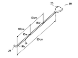
なお、例えば、ノズル本体22の長さは30cmであり、ノズル本体22の外径は3.7mmであり、シース14の内径は4.5mmである。このため、シース14の内面14aとノズル本体22との間には0.4mmの隙間14dがある。隙間14dは、腹腔72内の圧力が上昇したとき、隙間14dを介して腹腔72内のガスGLを体外へ排出する排気路として機能するものである。腹腔72内のガスGLは、シース14の先端部14bから隙間14dを通り、シース14の後端部14cを経て体外に排出される。この場合、シース14の先端部14bがガス取り入れ口として機能し、シース14の後端部14cがガスリーク出口として機能する。
シース14は、両端が開口した長尺状の管体で構成されており、その内部には、ノズルヘッド24の一部およびノズル本体22が挿通されている。本実施形態では、シース14は、ノズルヘッド24の湾曲部分よりも先端側の部分からノズル本体22のスプレーヘッド20の接続部の近傍まで挿入されている。また、シース14は、ノズル本体22およびノズルヘッド24に対し、ノズル本体22の長手軸方向に沿って相対的に移動可能である。
また、シース14は、後述するようにノズル本体22の湾曲部分の形状を規制する形状規制部材としての機能を有する。
また、シース14は、後述するようにノズル本体22の湾曲部分の形状を規制する形状規制部材としての機能を有する。
シース14には、その長手軸方向に沿って等間隔な複数の長手軸方向の形成位置におけるシース14の周上に、それぞれ複数の側孔が形成されている。具体的には、シース14の長手軸方向に沿って2箇所、先端部14b側の位置に側孔15aが形成され、後端部14c側の位置に側孔15bが形成されている。
ここで、側孔15a、15bは、シース14の先端部14bと側孔15aとの形成位置との間の間隔、側孔15aと側孔15bとの形成位置間の間隔および側孔15bの形成位置と後端部14cとの間の間隔とがシース14の長手軸方向に沿って等しくなるように形成されている。
長手軸方向の各形成位置において、側孔15aおよび側孔15bは、それぞれシース14の周方向に沿って等間隔で2つ形成されている。すなわち、それぞれ2つの側孔15a、15bは、各長手軸方向の形成位置の周上において対向して形成されている。
ここで、側孔15a、15bは、シース14の先端部14bと側孔15aとの形成位置との間の間隔、側孔15aと側孔15bとの形成位置間の間隔および側孔15bの形成位置と後端部14cとの間の間隔とがシース14の長手軸方向に沿って等しくなるように形成されている。
長手軸方向の各形成位置において、側孔15aおよび側孔15bは、それぞれシース14の周方向に沿って等間隔で2つ形成されている。すなわち、それぞれ2つの側孔15a、15bは、各長手軸方向の形成位置の周上において対向して形成されている。
各側孔15a、15bは、シース14を貫通し、隙間14dに連通しており、腹腔72内のガスGLが隙間14d内に流入する流入口、すなわち、腹腔72内のガスGLを取り入れる取入れ口として機能するものである。
図2に示すように、例えば、シース14の全長が30cmであれば、その長手軸方向に沿って10cm間隔で、先端部14bから10cmの位置に側孔15aが形成され、先端部14bから20cmの位置に側孔15bが形成される。側孔を形成する間隔は10cmに限定されるものではなく、5cmであってもよい。
側孔とガスリーク出口として機能する後端部14cとの距離によりガスリーク量が変わる。後端部14cに近い側孔程、ガスリーク量が多くなる。このため、側孔15bの方が側孔15aよりもガスリーク量が多い。
側孔とガスリーク出口として機能する後端部14cとの距離によりガスリーク量が変わる。後端部14cに近い側孔程、ガスリーク量が多くなる。このため、側孔15bの方が側孔15aよりもガスリーク量が多い。
シース14の長手軸方向に沿って複数の位置に、それぞれ複数の側孔15a、15bを形成することにより、腹腔72内のガスGLがシース14の先端部14bから隙間14dを通りシース14の後端部14c(ガスリーク出口)から体外に排出される経路以外に、側孔が腹腔72内にあれば、腹腔72内のガスGLが側孔を通り、隙間14dおよび後端部14cを経て体外に排出される経路がある。
また、トロカー50内に側孔が位置しているときには、腹腔72内のガスGLがトロカー50の本体52の先端部52aから入り、本体52とシース14との隙間53を通って、側孔15bを経てシース14の隙間14dを経て、後端部14cから体外に排出される経路がある。
このように、上述の側孔を形成することにより、上述の先端部14bからの経路以外に、腹腔72内のガスGLの体外への複数の排出経路が得られる。本実施形態の塗布具10は、上述のような腹腔72内のガスGLの体外に排出するガスリーク機能を備えている。
また、トロカー50内に側孔が位置しているときには、腹腔72内のガスGLがトロカー50の本体52の先端部52aから入り、本体52とシース14との隙間53を通って、側孔15bを経てシース14の隙間14dを経て、後端部14cから体外に排出される経路がある。
このように、上述の側孔を形成することにより、上述の先端部14bからの経路以外に、腹腔72内のガスGLの体外への複数の排出経路が得られる。本実施形態の塗布具10は、上述のような腹腔72内のガスGLの体外に排出するガスリーク機能を備えている。
シース14の先端部14b側に形成された2つの側孔15aは、例えば、腹腔圧が8~12mmHgで2~4L/minのリーク流量を確保するため、総面積が6.28mm2となる大きさに形成されている。また、シース14の後端部14c側に形成された2つの側孔15bについても、総面積が6.28mm2となる大きさに形成されている。
総面積が大きいと、リーク流量が4L/min超える。トロカー50では、腹腔72内のガスGLのリーク分に対して、腹腔圧を8~12mmHgに維持するために、制御部によりガス供給部60から無菌ガスGvが供給されるが、リーク流量が4L/min超えると、その供給量が多くなる。
また、総面積が小さいと、リーク流量が2L/min未満になり、塗布具10を用いた処置の際に、腹腔圧が8~12mmHg以上に上昇する虞がある。
総面積が大きいと、リーク流量が4L/min超える。トロカー50では、腹腔72内のガスGLのリーク分に対して、腹腔圧を8~12mmHgに維持するために、制御部によりガス供給部60から無菌ガスGvが供給されるが、リーク流量が4L/min超えると、その供給量が多くなる。
また、総面積が小さいと、リーク流量が2L/min未満になり、塗布具10を用いた処置の際に、腹腔圧が8~12mmHg以上に上昇する虞がある。
本実施形態において、側孔15a、15bの大きさは、リーク流量を考慮すると直径3mm以下が好ましい。特に好ましくは、直径2mmである。
また、同じ形成位置に設ける側孔の数は、本実施形態では2つであったが、2つに限定されるものではなく、3つ以上であってもよい。なお、同じ形成位置に設ける側孔の数が1つである場合、ノズル本体22が片寄ってシース14の内面14aと接することがあり、このとき、側孔を塞いでしまう虞がある。この場合、塞がれた側孔は腹腔72内のガスGLの排出経路として機能しなくなる。そこで、同じ形成位置に設ける側孔の数は2以上である。
なお、シース14の長手軸方向における側孔の形成位置、および各形成位置でのシース14の周方向における側孔の数等は、腹腔圧を8~12mmHgに保持し、かつリーク流量が2~4L/minとなるようにできれば、特に限定されるものではなく、適宜決定することができる。
シース14は、ノズルヘッド24の湾曲部分の一部または全部を覆ったときに、ノズルヘッド24の湾曲部分の形状を規制し得る材料で構成されている。シース14の構成材料としては、例えば、ポリエチレンが用いられる。
ノズル12を構成するスプレーヘッド20には、ノズル本体22が設けられたのとは反対側に、第1のシリンジ34aと接続される第1の接続部30a、および第2のシリンジ34bと接続される第2の接続部30bが設けられている。
第1の接続部30aには第1の内管32aが接続されている。この第1の内管32aは、第1のシリンジ34aから供給される第1の液体をノズルヘッド24から噴出させるためのものであり、ノズル本体22内を挿通されて、更にはノズルヘッド24に接続されている。
第2の接続部30bには第2の内管32bが接続されている。この第2の内管32bは、第2のシリンジ34bから供給される第2の液体をノズルヘッド24から噴出させるためのものであり、ノズル本体22内を挿通され、更にはノズルヘッド24に接続されている。
第2の接続部30bには第2の内管32bが接続されている。この第2の内管32bは、第2のシリンジ34bから供給される第2の液体をノズルヘッド24から噴出させるためのものであり、ノズル本体22内を挿通され、更にはノズルヘッド24に接続されている。
第1のシリンジ34aおよび第2のシリンジ34bは、押圧部36に接続されている。
押圧部36は、第1のシリンジ34aおよび第2のシリンジ34bを押圧するものであり、その構成は、特に限定されるものではなく、押圧することができれば手動、自動のいずれでもよい。
押圧部36により第1のシリンジ34aおよび第2のシリンジ34bが押圧される。これにより、第1の液体を第1の内管32aに、第2の液体を第2の内管32bに容易かつ確実に供給することができる。また、押圧部36の押圧操作は、塗布具10の操作者の操作により、自身の任意のタイミングで行なうことができる。
押圧部36は、第1のシリンジ34aおよび第2のシリンジ34bを押圧するものであり、その構成は、特に限定されるものではなく、押圧することができれば手動、自動のいずれでもよい。
押圧部36により第1のシリンジ34aおよび第2のシリンジ34bが押圧される。これにより、第1の液体を第1の内管32aに、第2の液体を第2の内管32bに容易かつ確実に供給することができる。また、押圧部36の押圧操作は、塗布具10の操作者の操作により、自身の任意のタイミングで行なうことができる。
第1のシリンジ34aに充填される第1の液体と、第2のシリンジ34bに充填される第2の液体は、それぞれの組成が異なる。
第1の液体と第2の液体とは、塗布具10の用途、使用目的、症例等に応じて適宜選定される。例えば、癒着防止材の塗布に用いる場合、例えば、第1の液体および第2の液体のうちの一方は、スクシンイミジル基で修飾したカルボキシメチルデキストリンを含有する液体であり、他方は、炭酸ナトリウムおよび炭酸水素ナトリウムを含有する液体である。
また、生体組織接着材の塗布に用いる場合、第1の液体および第2の液体のうちの一方は、トロンビンを含有する液体であり、他方はフィブリノーゲンを含有する液体である。
第1の液体と第2の液体とは、塗布具10の用途、使用目的、症例等に応じて適宜選定される。例えば、癒着防止材の塗布に用いる場合、例えば、第1の液体および第2の液体のうちの一方は、スクシンイミジル基で修飾したカルボキシメチルデキストリンを含有する液体であり、他方は、炭酸ナトリウムおよび炭酸水素ナトリウムを含有する液体である。
また、生体組織接着材の塗布に用いる場合、第1の液体および第2の液体のうちの一方は、トロンビンを含有する液体であり、他方はフィブリノーゲンを含有する液体である。
このような組み合わせの第1の液体および第2の液体は、それらを混合すると、ゲル化する。ゲル化することにより、例えば、第1の液体と第2の液体とが混合したもの(以下、「混合液」という)が、塗布された生体組織(目的部位)に確実に留まることができる。また、混合液が目的部位に確実に留まるため、塗布された生体組織(目的部位)で、生体組織接着材や癒着防止材としての機能を確実に発揮することができる。
なお、第1の液体および第2の液体の種類および組み合わせは、上述のものに限定されるものではない。
なお、第1の液体および第2の液体の種類および組み合わせは、上述のものに限定されるものではない。
スプレーヘッド20には、ノズル本体22に連通したポート29が設けられている。このポート29にはチューブ37を介してガス供給部38が設けられている。ポート29は、ガス供給部38のガス供給口の接続口として機能する。
ガス供給部38は、無菌ガスGが高圧に充填されたガスボンベ(図示せず)を備えている。無菌ガスGは、後述する混合液Lcを噴出させるためのものであり、例えば、窒素ガスあるいは空気が用いられる。
ガス供給部38により、無菌ガスGをノズルヘッド24に速い流速で供給することができる。ガス供給部38またはチューブ37には、無菌ガスGの供給、供給停止を制御するための開閉自在なバルブ(図示せず)が設置されている。後述する混合液Lcを塗布する際には、このバルブを開状態にする。
なお、第1のシリンジ34aおよび第2のシリンジ34bと押圧部36、およびガス供給部38により供給部が構成される。
ガス供給部38は、無菌ガスGが高圧に充填されたガスボンベ(図示せず)を備えている。無菌ガスGは、後述する混合液Lcを噴出させるためのものであり、例えば、窒素ガスあるいは空気が用いられる。
ガス供給部38により、無菌ガスGをノズルヘッド24に速い流速で供給することができる。ガス供給部38またはチューブ37には、無菌ガスGの供給、供給停止を制御するための開閉自在なバルブ(図示せず)が設置されている。後述する混合液Lcを塗布する際には、このバルブを開状態にする。
なお、第1のシリンジ34aおよび第2のシリンジ34bと押圧部36、およびガス供給部38により供給部が構成される。
ノズル本体22は、例えば、ステンレス鋼により構成された管状のものであり、中空ステンレスシャフトで構成される。ノズル本体22は、例えば、長さが30cmである。上述のように、ノズル本体22の内部は、第1の内管32aおよび第2の内管32bが挿通されており、かつ無菌ガスGが通過する。
ノズルヘッド24は、ノズル本体22の先端部に設けられたものである。このノズルヘッド24は、中空であり、内部にノズル部26が設けられている。ノズル部26に第1の内管32aおよび第2の内管32bが接続されており、第1の内管32aを通って供給された第1の液体と、第2の内管32bを通って供給された第2の液体とがノズル部26内で混合される。
ノズル部26は、ノズルヘッド24の開口部24aに一部が挿入されており、例えば、開口部24aに挿入された部分以外は、多孔質材で形成されている。
これにより、押圧部36の操作により、第1の液体と第2の液体とがノズル部26に供給されて、更に、ガス供給部38からノズル本体22内部を通過してノズル部26に流入した無菌ガスGによって、ノズル部26内の混合液Lcを開口部24aから確実に噴射させることができる。なお、混合液Lcとは、第1の液体、第2の液体および無菌ガスGが混合されたものである。
ノズル部26は、ノズルヘッド24の開口部24aに一部が挿入されており、例えば、開口部24aに挿入された部分以外は、多孔質材で形成されている。
これにより、押圧部36の操作により、第1の液体と第2の液体とがノズル部26に供給されて、更に、ガス供給部38からノズル本体22内部を通過してノズル部26に流入した無菌ガスGによって、ノズル部26内の混合液Lcを開口部24aから確実に噴射させることができる。なお、混合液Lcとは、第1の液体、第2の液体および無菌ガスGが混合されたものである。
ノズルヘッド24において、混合液Lcを噴出しているときには、ノズル部26を透過した無菌ガスGは、ノズル部26を通過する混合液中でマイクロバブルとなる。このマイクロバブルにより、混合液Lcは、ノズル部26を通過する過程で攪拌される。これにより、第1の液体と第2の液体とは、均一かつ確実に混合し、混合液Lcとなって開口部24aから噴出される。特に、両液体の粘度が互いに異なる場合には、これら液体同士を単に合流するだけでは均一な混合液になり難いが、マイクロバブルを利用することにより、第1の液体と第2の液体とを攪拌してそれらの混合を促進する攪拌作用を発揮するため、均一な混合液Lcが得られる。
ノズルヘッド24は、柔軟性を有するものであり、例えば、ノズルヘッド24の先端が斜め上側を向くように湾曲している。ノズルヘッド24の軸線g2は、ノズル本体22の軸線g1に対して所定の角度傾斜している。
ノズルヘッド24は、後述するシース14により規制されることなく湾曲した状態のときのノズル本体22の軸線g1に対するノズルヘッド24の軸線g2の傾斜角度θは、30~90°程度であることが好ましく、70°~90°程度であることがより好ましい。
ノズルヘッド24の湾曲部分は、例えば、軟質材料、弾性材料等で構成されている。なお、ノズルヘッド24の湾曲部分より基端側の部分は、硬質材料で構成されているものでも、軟質材料、弾性材料等で構成され、可撓性を有するものでもよい。
また、ノズルヘッド24の湾曲部分と、ノズルヘッド24の湾曲部分より基端側の部分とは、別部材で構成され、接着、融着等により固着された構成でもよく、また、一体成形された構成であってもよい。
また、ノズルヘッド24の湾曲部分と、ノズルヘッド24の湾曲部分より基端側の部分とは、別部材で構成され、接着、融着等により固着された構成でもよく、また、一体成形された構成であってもよい。
ノズルヘッド24としては、例えば、米国特許出願公開第2009/0124986号明細書の図18~図26に開示の構成とすることもできる。なお、ノズル部26は、上述のように一部が多孔質材で構成されているが、これに限定されず、例えば、全体が多孔質材で構成されていてもよい。
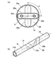
ノズル本体22は、スプレーヘッド20側の基端部28に、図3(a)、(b)に示すように、例えば、2個の潰し部28a、28bが設けられている。
各潰し部28a、28bは、ノズル本体22の基端部28を、例えば、プレスにより、ノズル本体22の両側から押圧して、内部に第1の内管32aおよび第2の内管32bが挿通可能なスペースを残して、ノズル本体22をプレスによって押圧される押圧方向と直交する方向(以下、押圧方向と直交する方向を変形方向という。)に変形させて形成したものである。各潰し部28a、28bは、ノズル本体22を上述のように変形方向に変形させて形成された偏平部である。
潰し部28aと潰し部28bとは、それぞれノズル本体22の軸線g1に対して押圧方向を、所定の角度αずらして、かつ隣接して形成されている。ずらす角度αは、例えば、90°である。すなわち、潰し部28aと潰し部28bは、それぞれ変形方向が異なり、各潰し部28a、28bの変形方向のなす角度は90°である。なお、ずらす角度αおよび各潰し部28a、28bの変形方向のなす角度を、以下、設置角度ともいう。
潰し部28a、28bは、それぞれシース14の内面14aと摺動抵抗が生じる程度に接触するものであり、好ましくは、シース14の内径よりも大きくシース14の外面を外側に押し出すことができる大きさである。このように、各潰し部28a、28bは隣接してそれぞれ異なる変形方向でシース14の内面14aと接触している。
各潰し部28a、28bを上述のように形成することにより、シース14の内面14aと接する状態でシース14とノズル本体22とを、シース14の長手軸方向に沿って相対的に移動させると、各潰し部28a、28bとシース14の内面14aが摺動し、シース14の内面14aと隣接する各潰し部28a、28bとの間に摩擦抵抗が生じ、所要の摺動抵抗を得ることができる。
各潰し部28a、28bを離間して設けた場合、潰し部を1つ設けたものと同様に、シース14が変形した場合に、摺動抵抗が低下する。このため、潰し部28a、28bは隣接して設けることが好ましい。
各潰し部28a、28bを離間して設けた場合、潰し部を1つ設けたものと同様に、シース14が変形した場合に、摺動抵抗が低下する。このため、潰し部28a、28bは隣接して設けることが好ましい。
本実施形態においては、ノズル本体22の潰し部28aと潰し部28bとは、シース14の異なる方向において隣接して接続しているので、接触部分におけるシース14の変形方向または拡径方向が異なるため、両者の摺動抵抗を向上させることができる。例えば、オートクレーブを用いた滅菌時の加熱、または経年変化等により、シース14が変形し、例えば、拡径した場合でも、特に異なる2方向のうちの一方向の変形や拡径であれば、隣接する潰し部28a、28bのうち、いずれかがシース14の内面14aに接した状態に維持できるため、摺動抵抗の低下を抑制することができる。これにより、シース14の変形による塗布具10の操作性の悪化を抑制することができる。しかも、異なる2方向の変形や拡径が起こる前に、一方向の変形や拡径が起こる可能性が高いため、シース14の経年変化等にも対応することができ、塗布具10について、長期に亘り、安定した操作性を得ることができる。
なお、オートクレーブを用いた滅菌時の加熱、または経年変化等によりシース14が変形しても、摺動抵抗の低下を抑制することができれば、潰し部の数は、特に限定されるものではない。
なお、オートクレーブを用いた滅菌時の加熱、または経年変化等によりシース14が変形しても、摺動抵抗の低下を抑制することができれば、潰し部の数は、特に限定されるものではない。
各潰し部28a、28bの大きさは、例えば、長手軸方向の長さが3~10mmであり、好ましくは4~6mmである。また、潰し部28a、28bの径方向の幅は、例えば、シース14の内径よりも0.1~0.9mm大きいものであり、好ましくは0.2~0.6mm大きい。
潰し部28a、28bの数は、2個以上であれば効果を発揮できるが、2個が望ましい。潰し部28a、28bの数が多すぎるとノズルの曲げ強度が低下する愚がある。
潰し部28a、28bの設置角度は、90°±30°(60°~120°)が好ましく、90°±20°(70°~110°)がより好ましい。
また、潰し部28a、28bの隣接間隔は、2~20mmが好ましく、3~10mmがより好ましい。潰し部28a、28b間の間隔が短いと加工が難しくなる。一方、潰し部28a、28bの間隔が長すぎると経年変化に対する摺動抵抗の低下が抑制できなくなる。
潰し部28a、28bの数は、2個以上であれば効果を発揮できるが、2個が望ましい。潰し部28a、28bの数が多すぎるとノズルの曲げ強度が低下する愚がある。
潰し部28a、28bの設置角度は、90°±30°(60°~120°)が好ましく、90°±20°(70°~110°)がより好ましい。
また、潰し部28a、28bの隣接間隔は、2~20mmが好ましく、3~10mmがより好ましい。潰し部28a、28b間の間隔が短いと加工が難しくなる。一方、潰し部28a、28bの間隔が長すぎると経年変化に対する摺動抵抗の低下が抑制できなくなる。
また、各潰し部28a、28bは、例えば、ノズル本体22の長手軸方向に中間部に設けた場合、トロカー50の開口部56に引っ掛る等して作業性が著しく悪くなるため、ノズル本体22の基端部28に設ける。
更には、各潰し部28a、28bは摺動抵抗が高く、シース14を移動して所定の停止位置に停止させておくことができるため、その停止位置でシース14のノズル12の長手軸方向に対する位置決めを行う位置決め手段として機能する。これにより、ノズルヘッド24を所定の傾斜角度θを維持した状態で混合液Lcを噴出することができる。
また、上述のように、塗布具10はトロカー50に挿入した状態で用いられる。この状態で、塗布具10を先端方向に押し込んでいくと、シース14の各潰し部28a、28bが位置する部分の外周部が本体52の開口部56の縁部に当接することとなる。このため、シース14のトロカー50に対する先端方向への移動限界を規制することができる。これにより、塗布具10のシース14がトロカー50内に不本意に入り込んでしまうことを防止することができ、各潰し部28a、28bはシース14のトロカー50に対する先端方向への移動限界を規制する規制手段としても機能する。
本実施形態において、ノズル本体22の潰し部28aと潰し部28bによるシース14の摺動抵抗は3.0~11.0Nであることが好ましい。この程度の摺動抵抗となるように、潰し部は、大きさ、数および配置角度が決定されて、形成されている。なお、シース14の摺動抵抗は、以下に示すようにして測定されたものである。
シースの摺動抵抗の測定方法について、図4(a)、(b)に基づいて説明する。なお、図4(a)、(b)において、図1に示す塗布具10と同様の構成については同一符号を付し、その詳細な説明は省略する。
シースの摺動抵抗の測定方法について、図4(a)、(b)に基づいて説明する。なお、図4(a)、(b)において、図1に示す塗布具10と同様の構成については同一符号を付し、その詳細な説明は省略する。
まず、ノズル本体22を引く場合のシースの摺動抵抗の測定方法について説明する。
図4(a)に示すように、固定ジグ80をオートグラフ(図示せず)に設置に、フレア加工部82を用いて固定ジグ80に塗布具10を、ノズルヘッド24を下側にして固定する。次に、スプレーヘッド20をオートグラフのロードセル側のチャックで把持する。
次に、下記引張試験条件にて、スプレーヘッド20を引張り、そのとき、ノズルヘッド24がシース14に触れる直前までに生じる最大力を測定し、この最大力を、ノズル本体22を引く場合のシース14の摺動抵抗値とした。
引張試験条件としては、チャック間距離D(図4(a)参照)を31.5±0.5mmとし、引張速度を100mm/分とし、ストローク距離を17.0mmとした。
なお、チャック間距離Dとは、固定ジグ80面から符号84で示す凸部までのチャック間距離のことである。この凸部84は、図1のポート29に相当するものであり、ガス供給口の接続口である。
次に、ノズル本体22を押す場合のシースの摺動抵抗の測定方法について説明する。
図4(b)に示すように、固定ジグ80をオートグラフ(図示せず)に設置に、フレア加工部82を用いて固定ジグ80に塗布具10を、ノズルヘッド24を下側にして固定する。次に、スプレーヘッド20をオートグラフのロードセル側のチャックで把持する。
次に、下記押込み試験条件にて、スプレーヘッド20を押込み、そのとき、スプレーヘッド20がシース14に触れる直前までに生じる最大力を測定し、この最大力を、ノズル本体22を押す場合のシース14の摺動抵抗値とした。
押込み試験条件としては、チャック間距離D(図4(b)参照)を31.5±0.5mmとし、押込み速度を100mm/分とした。
図4(b)に示すように、固定ジグ80をオートグラフ(図示せず)に設置に、フレア加工部82を用いて固定ジグ80に塗布具10を、ノズルヘッド24を下側にして固定する。次に、スプレーヘッド20をオートグラフのロードセル側のチャックで把持する。
次に、下記押込み試験条件にて、スプレーヘッド20を押込み、そのとき、スプレーヘッド20がシース14に触れる直前までに生じる最大力を測定し、この最大力を、ノズル本体22を押す場合のシース14の摺動抵抗値とした。
押込み試験条件としては、チャック間距離D(図4(b)参照)を31.5±0.5mmとし、押込み速度を100mm/分とした。
塗布具10においては、シース14をノズル本体22の長手軸方向に沿って相対的に移動させた場合、シース14内にノズルヘッド24の湾曲部分が挿入される。このシース14の先端からのノズルヘッド24の湾曲部分の突出長を調整することにより、その湾曲部分の形状を変更することができる。これにより、ノズル本体22の軸線g1に対するノズルヘッド24の軸線g2の傾斜角度θ、すなわち、ノズルヘッド24の方向を調整することができる。具体的に、例えば、ノズルヘッド24の湾曲部分がシース14により規制されて直線状となり、ノズルヘッド24の軸線g2の方向とノズル本体22の軸線g1の方向とが一致する第1の位置(傾斜角度θ=0°)と、湾曲部分がシース14により規制されることなく湾曲した状態となり、ノズル本体22の軸線g1がノズルヘッド24の軸線g2に対して傾斜する第2の位置(傾斜角度θが最大傾斜角度)との間で、シース14は移動可能である。このため、シース14とノズル本体22との相対的な位置を、第1の位置と第2の位置との間の所定の位置に移動させることにより、ノズルヘッド24の傾斜角度θを0°から最大傾斜角度までの範囲内で自在に調整することができる。
本実施形態においては、上述のように各潰し部28a、28bはシース14の内面14aとの摺動抵抗が高く、シース14を所定の停止位置で停止させることができ、しかも、上述のように滅菌時の加熱に対しても、経年劣化に対しても耐性があり、シース14の内面14aとの高い摺動抵抗を長期に亘り維持することができる。このため、シース14によってノズルヘッド24の湾曲部分を正確に規制することができ、ノズルヘッド24の傾斜角度θを所定の角度に、正確に保って混合液Lcを塗布することができる。さらには、繰り返し使っても、ノズルヘッド24の傾斜角度θを所定の角度に、長期に亘り安定して正確に保って混合液Lcを塗布することができる。
本実施形態においては、上述のように各潰し部28a、28bはシース14の内面14aとの摺動抵抗が高く、シース14を所定の停止位置で停止させることができ、しかも、上述のように滅菌時の加熱に対しても、経年劣化に対しても耐性があり、シース14の内面14aとの高い摺動抵抗を長期に亘り維持することができる。このため、シース14によってノズルヘッド24の湾曲部分を正確に規制することができ、ノズルヘッド24の傾斜角度θを所定の角度に、正確に保って混合液Lcを塗布することができる。さらには、繰り返し使っても、ノズルヘッド24の傾斜角度θを所定の角度に、長期に亘り安定して正確に保って混合液Lcを塗布することができる。
このように、シース14を移動させて、傾斜角度θを適宜調整することによってノズルヘッド24の傾斜角度θを変えつつ、上述のようにして、ノズルヘッド24の開口部24aから混合液Lcを腹腔72内の複数の箇所、例えば、臓器や腹壁70に向けて、容易かつ確実に広範囲にわたって、しかも長期に亘り安定して塗布することができる。
なお、塗布具10では、外力が付与されていない自然状態での湾曲部分の湾曲の程度(傾斜角度θ)を適宜設定することにより、例えば「U」字状にすれば腹壁70にも混合液Lcを塗布することができる。
なお、塗布具10では、外力が付与されていない自然状態での湾曲部分の湾曲の程度(傾斜角度θ)を適宜設定することにより、例えば「U」字状にすれば腹壁70にも混合液Lcを塗布することができる。
ここで、図5(a)および(b)は、本発明の実施形態の塗布具の使用形態を模式図であり、図5(c)は、従来の塗布具の使用形態を示す模式図である。図5(a)~(c)においては、図1に示す塗布具10と同一構成物には同一符号を付し、その詳細な説明は省略する。
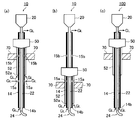
図5(a)に示すように、塗布具10を、上側の側孔15bが腹腔72内に入るように腹腔72内に挿入した場合、腹腔72内のガスGLの排出経路としては、シース14の先端部14bを経る第1の経路、側孔15aを経る第2の経路、および側孔15bを経る第3の経路の合計3つの排出経路がある。このため、シース14の先端部14bが腹腔72内にある腹水、洗浄液等の液体で塞がれてしまった場合に、塗布具10の無菌ガスGを用いた混合液Lcの噴射により、腹腔72内の圧力が高くなっても、上述の第2の経路、および第3の経路から腹腔72内のガスGLを体外に排出することができる。
また、図5(b)に示すように、塗布具10の腹腔72内への挿入長さが浅く、上側の側孔15bが腹壁70外にあるように塗布具10を腹腔72内に挿入した場合、腹腔72内のガスGLの排出経路としては、上述の第1の経路および第2の経路の合計2つの排出経路がある。このため、シース14の先端部14bが腹腔72内にある腹水、洗浄液等の液体で塞がれてしまった場合に、塗布具10の無菌ガスGを用いた混合液Lcの噴射により、腹腔72内の圧力が高くなっても、上述の第2の経路から腹腔72内のガスGLを体外に排出することができる。
図5(c)に示すように、側孔がない従来の塗布具100では、腹腔72内のガスGLの排出経路が上述の第1の経路しかない。このため、シース14の先端部14bが腹腔72内にある腹水、洗浄液等の液体で塞がれてしまった場合に、塗布具10の無菌ガスGを用いた混合液Lcの噴射により、腹腔72内の圧力が高くなっても、腹腔72内のガスGLを体外に排出することができない。
上述のように、本実施形態の塗布具10では、塗布具10の挿入の深さが変わっても、その影響を受けることなく、ガスリーク機能が維持される。このため、塗布具10の無菌ガスGを用いた混合液Lcの噴射により、腹腔72内の圧力が高くなっても、腹腔72内のガスGLを体外に排出することができ、腹腔72内の圧力上昇を抑制することができる。更には、複数の排出経路があるため、排出経路の1つが塞がれても、上述と同様にガスリーク機能が維持され、塗布具10の使用による腹腔72内の圧力上昇を抑制することができる。
上述のように、本実施形態の塗布具10では、塗布具10の挿入の深さが変わっても、その影響を受けることなく、ガスリーク機能が維持される。このため、塗布具10の無菌ガスGを用いた混合液Lcの噴射により、腹腔72内の圧力が高くなっても、腹腔72内のガスGLを体外に排出することができ、腹腔72内の圧力上昇を抑制することができる。更には、複数の排出経路があるため、排出経路の1つが塞がれても、上述と同様にガスリーク機能が維持され、塗布具10の使用による腹腔72内の圧力上昇を抑制することができる。
本発明は、基本的に以上のように構成されるものである。以上、本発明の塗布具について詳細に説明したが、本発明は上記実施形態に限定されず、本発明の主旨を逸脱しない範囲において、種々の改良または変更をしてもよいのはもちろんである。
10 塗布具
12 ノズル
14 シース
14d、53 隙間
15a、15b 側孔
20 スプレーヘッド
22 ノズル本体
24 ノズルヘッド
26 ノズル部
28 端部
28a、28b 潰し部
30b 第2の接続部
30a 第1の接続部
34a 第1のシリンジ
34b 第2のシリンジ
36 押圧部
38、60 ガス供給部
50 トロカー
72 腹腔
80 固定ジグ
Lc 混合液
12 ノズル
14 シース
14d、53 隙間
15a、15b 側孔
20 スプレーヘッド
22 ノズル本体
24 ノズルヘッド
26 ノズル部
28 端部
28a、28b 潰し部
30b 第2の接続部
30a 第1の接続部
34a 第1のシリンジ
34b 第2のシリンジ
36 押圧部
38、60 ガス供給部
50 トロカー
72 腹腔
80 固定ジグ
Lc 混合液
Claims (3)
- ガスおよび複数種の液体が供給される長尺状のノズル本体、ならびに前記ノズル本体の先端側に設けられ、前記ノズル本体に供給されたガスおよび複数種の液体の混合液を噴出するノズルヘッドを備えるノズルと、
前記ノズル本体がその長手軸方向に沿って相対的に移動可能に挿通されたシースとを有し、生体内に挿入され、生体内の部位に前記混合液を塗布する塗布具であって、
前記ノズル本体と前記シースとの間には隙間が設けられており、前記間隙は、前記生体内の圧力が上昇したときに前記生体内のガスを生体外へ排出する排出路として機能するものであり、
前記シースには、その長手軸方向に沿って等間隔な複数の位置の周上に、それぞれ前記隙間に連通する複数の側孔が形成されていることを特徴とする塗布具。 - 前記複数の側孔は、前記シースの長手軸方向に沿った前記複数の位置の各々において、前記シースの周方向に沿って等間隔に形成されている請求項1に記載の塗布具。
- 前記シースの長手軸方向に沿った前記複数の位置の各々において前記周方向に沿って形成された前記複数の側孔の数は、2または3である請求項1または2に記載の塗布具。
Priority Applications (2)
| Application Number | Priority Date | Filing Date | Title |
|---|---|---|---|
| EP13761434.3A EP2826427B1 (en) | 2012-03-15 | 2013-03-05 | Applicator |
| US14/486,194 US20150005698A1 (en) | 2012-03-15 | 2014-09-15 | Applicator |
Applications Claiming Priority (2)
| Application Number | Priority Date | Filing Date | Title |
|---|---|---|---|
| JP2012-058267 | 2012-03-15 | ||
| JP2012058267 | 2012-03-15 |
Related Child Applications (1)
| Application Number | Title | Priority Date | Filing Date |
|---|---|---|---|
| US14/486,194 Continuation US20150005698A1 (en) | 2012-03-15 | 2014-09-15 | Applicator |
Publications (1)
| Publication Number | Publication Date |
|---|---|
| WO2013137062A1 true WO2013137062A1 (ja) | 2013-09-19 |
Family
ID=49160975
Family Applications (1)
| Application Number | Title | Priority Date | Filing Date |
|---|---|---|---|
| PCT/JP2013/055983 WO2013137062A1 (ja) | 2012-03-15 | 2013-03-05 | 塗布具 |
Country Status (4)
| Country | Link |
|---|---|
| US (1) | US20150005698A1 (ja) |
| EP (1) | EP2826427B1 (ja) |
| JP (1) | JPWO2013137062A1 (ja) |
| WO (1) | WO2013137062A1 (ja) |
Cited By (1)
| Publication number | Priority date | Publication date | Assignee | Title |
|---|---|---|---|---|
| WO2016140039A1 (ja) * | 2015-03-04 | 2016-09-09 | オリンパス株式会社 | 挿入具及び医療処置システム |
Families Citing this family (2)
| Publication number | Priority date | Publication date | Assignee | Title |
|---|---|---|---|---|
| US10625032B2 (en) | 2016-08-16 | 2020-04-21 | Ethicon, Inc. | Spray tips for simultaneous multi-directional delivery of dissimilar fluids |
| US10835284B2 (en) * | 2016-10-13 | 2020-11-17 | Lexion Medical, Llc | Method and system for controlling pressurization of a patient cavity using cavity distension measured by a pressure sensor of a trocar |
Citations (4)
| Publication number | Priority date | Publication date | Assignee | Title |
|---|---|---|---|---|
| US20090124986A1 (en) | 2007-11-08 | 2009-05-14 | Terumo Kabushiki Kaisha | Sprayer |
| WO2009107619A1 (ja) * | 2008-02-29 | 2009-09-03 | テルモ株式会社 | 塗布具 |
| WO2010044462A1 (ja) * | 2008-10-17 | 2010-04-22 | 学校法人 聖マリアンナ医科大学 | 骨セメント注入用穿刺針 |
| JP2011182994A (ja) * | 2010-03-09 | 2011-09-22 | Terumo Corp | 骨セメント注入用穿刺針 |
Family Cites Families (3)
| Publication number | Priority date | Publication date | Assignee | Title |
|---|---|---|---|---|
| US7611494B2 (en) * | 2005-02-08 | 2009-11-03 | Confluent Surgical, Inc. | Spray for fluent materials |
| US8210453B2 (en) * | 2008-09-12 | 2012-07-03 | Confluent Surgical, Inc. | Spray applicator |
| WO2010084869A1 (ja) * | 2009-01-21 | 2010-07-29 | 国立大学法人大阪大学 | 気腹形成および体腔内到達路形成用ガイドチューブシステム |
-
2013
- 2013-03-05 EP EP13761434.3A patent/EP2826427B1/en active Active
- 2013-03-05 WO PCT/JP2013/055983 patent/WO2013137062A1/ja active Application Filing
- 2013-03-05 JP JP2014504808A patent/JPWO2013137062A1/ja active Pending
-
2014
- 2014-09-15 US US14/486,194 patent/US20150005698A1/en not_active Abandoned
Patent Citations (6)
| Publication number | Priority date | Publication date | Assignee | Title |
|---|---|---|---|---|
| US20090124986A1 (en) | 2007-11-08 | 2009-05-14 | Terumo Kabushiki Kaisha | Sprayer |
| WO2009107619A1 (ja) * | 2008-02-29 | 2009-09-03 | テルモ株式会社 | 塗布具 |
| JP2009226189A (ja) | 2008-02-29 | 2009-10-08 | Terumo Corp | 塗布具 |
| US20100331766A1 (en) | 2008-02-29 | 2010-12-30 | Terumo Kabushiki Kaisha | Applicator |
| WO2010044462A1 (ja) * | 2008-10-17 | 2010-04-22 | 学校法人 聖マリアンナ医科大学 | 骨セメント注入用穿刺針 |
| JP2011182994A (ja) * | 2010-03-09 | 2011-09-22 | Terumo Corp | 骨セメント注入用穿刺針 |
Cited By (1)
| Publication number | Priority date | Publication date | Assignee | Title |
|---|---|---|---|---|
| WO2016140039A1 (ja) * | 2015-03-04 | 2016-09-09 | オリンパス株式会社 | 挿入具及び医療処置システム |
Also Published As
| Publication number | Publication date |
|---|---|
| EP2826427A1 (en) | 2015-01-21 |
| EP2826427B1 (en) | 2018-04-25 |
| JPWO2013137062A1 (ja) | 2015-08-03 |
| EP2826427A4 (en) | 2015-10-21 |
| US20150005698A1 (en) | 2015-01-01 |
Similar Documents
| Publication | Publication Date | Title |
|---|---|---|
| US8888691B2 (en) | Expanding surgical access port | |
| KR101441729B1 (ko) | 도포구 | |
| EP3758614B1 (en) | Adapter manifold for multi-barrel syringe applicator | |
| US8092431B2 (en) | Seal assembly for a cannula | |
| US9878126B2 (en) | Nozzle for the supply of biological material, in particular cells, medical device with such a nozzle, use of a nozzle, method for mixing fluids and apparatus | |
| US8523806B2 (en) | Sprayer | |
| WO2013137062A1 (ja) | 塗布具 | |
| EP3788964A1 (en) | Spray tips for simultaneous multi-directional delivery of dissimilar fluids | |
| US9603589B2 (en) | Delivery tip for extravascular bioadhesive catheter and methods | |
| US9119606B2 (en) | Sealant delivery device for anastomotic stapler | |
| CN107106152B (zh) | 至医疗施用装置的添加件 | |
| US10413683B2 (en) | Device and method for discharging a reactive liquid | |
| US20120245423A1 (en) | Retention member for laparoscopic access device | |
| WO2013137063A1 (ja) | 塗布具 | |
| JP6095693B2 (ja) | 塗布具 | |
| WO2022014159A1 (ja) | 医療用塗布具 | |
| US20020128660A1 (en) | Apparatus particularly for operative placement of surgical instruments in cavities under controlled pressure | |
| JP2005177141A (ja) | 生体組織用薬剤の供給器具 |
Legal Events
| Date | Code | Title | Description |
|---|---|---|---|
| 121 | Ep: the epo has been informed by wipo that ep was designated in this application |
Ref document number: 13761434 Country of ref document: EP Kind code of ref document: A1 |
|
| ENP | Entry into the national phase |
Ref document number: 2014504808 Country of ref document: JP Kind code of ref document: A |
|
| WWE | Wipo information: entry into national phase |
Ref document number: 2013761434 Country of ref document: EP |
|
| NENP | Non-entry into the national phase |
Ref country code: DE |