WO2013136893A1 - Powder supply apparatus and powder supply method - Google Patents
Powder supply apparatus and powder supply method Download PDFInfo
- Publication number
- WO2013136893A1 WO2013136893A1 PCT/JP2013/053250 JP2013053250W WO2013136893A1 WO 2013136893 A1 WO2013136893 A1 WO 2013136893A1 JP 2013053250 W JP2013053250 W JP 2013053250W WO 2013136893 A1 WO2013136893 A1 WO 2013136893A1
- Authority
- WO
- WIPO (PCT)
- Prior art keywords
- powder
- flow rate
- valve
- powder flow
- feed tank
- Prior art date
Links
Images


Classifications
-
- F—MECHANICAL ENGINEERING; LIGHTING; HEATING; WEAPONS; BLASTING
- F23—COMBUSTION APPARATUS; COMBUSTION PROCESSES
- F23K—FEEDING FUEL TO COMBUSTION APPARATUS
- F23K3/00—Feeding or distributing of lump or pulverulent fuel to combustion apparatus
-
- F—MECHANICAL ENGINEERING; LIGHTING; HEATING; WEAPONS; BLASTING
- F23—COMBUSTION APPARATUS; COMBUSTION PROCESSES
- F23K—FEEDING FUEL TO COMBUSTION APPARATUS
- F23K3/00—Feeding or distributing of lump or pulverulent fuel to combustion apparatus
- F23K3/02—Pneumatic feeding arrangements, i.e. by air blast
-
- F—MECHANICAL ENGINEERING; LIGHTING; HEATING; WEAPONS; BLASTING
- F23—COMBUSTION APPARATUS; COMBUSTION PROCESSES
- F23K—FEEDING FUEL TO COMBUSTION APPARATUS
- F23K2203/00—Feeding arrangements
- F23K2203/006—Fuel distribution and transport systems for pulverulent fuel
-
- F—MECHANICAL ENGINEERING; LIGHTING; HEATING; WEAPONS; BLASTING
- F23—COMBUSTION APPARATUS; COMBUSTION PROCESSES
- F23K—FEEDING FUEL TO COMBUSTION APPARATUS
- F23K2203/00—Feeding arrangements
- F23K2203/10—Supply line fittings
- F23K2203/103—Storage devices
-
- F—MECHANICAL ENGINEERING; LIGHTING; HEATING; WEAPONS; BLASTING
- F23—COMBUSTION APPARATUS; COMBUSTION PROCESSES
- F23K—FEEDING FUEL TO COMBUSTION APPARATUS
- F23K2203/00—Feeding arrangements
- F23K2203/10—Supply line fittings
- F23K2203/104—Metering devices
-
- F—MECHANICAL ENGINEERING; LIGHTING; HEATING; WEAPONS; BLASTING
- F23—COMBUSTION APPARATUS; COMBUSTION PROCESSES
- F23K—FEEDING FUEL TO COMBUSTION APPARATUS
- F23K2203/00—Feeding arrangements
- F23K2203/20—Feeding/conveying devices
- F23K2203/201—Feeding/conveying devices using pneumatic means
Definitions
- the present invention relates to a powder supply apparatus and a powder supply method capable of suppressing the occurrence of undershoot of the powder flow rate while rapidly reducing the powder flow rate.
- a combustion furnace that burns pulverized fuel such as pulverized coal supplied from a powder supply device is known as a combustion furnace used in blast furnace facilities, thermal power plants, and the like.
- pulverized fuel is burned while being injected into the combustion furnace together with air.
- Combustion methods using pulverized coal as pulverized fuel are widely used because of the high combustibility of the coal itself.
- a gas transfer type powder supply device for transferring pulverized fuel by a carrier gas.
- the pulverized fuel in the feed tank is supplied to the powder transport pipe and is transported by the carrier gas in the powder transport pipe.
- Control of the supply amount (powder flow rate) of pulverized fuel per hour into the powder transport pipe is based on the opening of the powder valve provided at the discharge port at the bottom of the feed tank and the pressure in the feed tank.
- the pressure may be controlled by a differential pressure with respect to the pressure in the powder transport pipe (see Patent Document 1 below).
- the opening of the valve for powder and the pressure difference between the pressure in the feed tank and the pressure in the powder transport pipe are generally determined by a powder flow meter or the like provided in the powder transport pipe. It is controlled by feedback of body flow information.
- the powder flow rate is determined based on an instruction from a combustion furnace or the like to which the powder is supplied. Even when the powder flow rate is reduced, the powder flow rate becomes a predetermined target value. As described above, the information on the powder flow rate is fed back to the control of the opening degree of the powder valve, the control of the differential pressure between the pressure in the feed tank and the pressure in the powder transport pipe.
- the powder supply apparatus may be in a rapid load reduction mode in which the powder flow rate must be rapidly reduced due to a trouble in the combustion furnace to which the pulverized fuel is supplied.
- the powder flow rate is reduced instantaneously, a load is applied to the combustion furnace, which may lead to failure of the combustion furnace. Therefore, in the rapid load reduction mode, the powder flow rate must be reduced to a predetermined amount at a predetermined time.
- the powder valve is closed to a predetermined opening so that the powder flow rate becomes the target value without performing the feedback control described above, and the pressure in the feed tank and the powder It is conceivable to reduce the differential pressure from the pressure in the transport pipe. However, in this case, an undershoot may occur in which the powder flow rate is further reduced from the finally determined powder flow rate due to external factors such as pressure fluctuation at the powder supply destination.
- an object of the present invention is to provide a powder supply apparatus and a powder supply method capable of suppressing the occurrence of undershoot of the powder flow rate while rapidly reducing the powder flow rate.
- the present invention provides a powder supply apparatus for supplying powder in a feed tank to the outside of the feed tank from a powder transport pipe connected to the feed tank, the powder tank being connected to the feed tank.
- An internal pressure control valve for adjusting the pressure in the feed tank, a powder valve connected to the powder transport pipe, and a control unit for controlling the internal pressure control valve and the powder valve.
- the control unit is configured to reduce the powder flow rate supplied to the outside of the feed tank to a predetermined amount after a predetermined time, so that the powder flow rate becomes smaller than the predetermined amount after the predetermined time.
- the internal pressure control valve is set in an exhaust state to reduce the pressure in the feed tank, the powder valve is closed to a predetermined opening degree, and the powder flow rate is the predetermined value after the predetermined time. As soon as the powder flow rate becomes smaller than the predetermined powder flow rate before the predetermined time elapses, at least one of the internal pressure control valve and the powder valve is changed to the predetermined powder flow rate. The flow rate is controlled based on the information on the powder flow rate.
- the present invention provides a powder supply method for supplying powder in a feed tank to the outside of the feed tank from a powder transport pipe connected to the feed tank, the feed tank In a rapid load reduction mode in which the powder flow rate supplied to the outside is reduced to a predetermined amount after a predetermined time, the internal pressure adjustment connected to the feed tank so that the powder flow rate becomes smaller than the predetermined amount after the predetermined time
- the valve is in an exhaust state to reduce the pressure in the feed tank, the powder valve connected to the powder transport pipe is closed to a predetermined opening, and the powder flow rate is changed to the predetermined position after the predetermined time.
- At least one of the internal pressure control valve and the powder valve as soon as the powder flow rate becomes smaller than the scheduled powder flow rate before the predetermined time elapses for quantification. But, as the powder flow rate becomes the scheduled powder flow rate, is characterized in that is adjusted based on the powder flow rate information.
- the internal pressure control valve is in the exhaust state and the powder valve is closed to a predetermined opening in the rapid load reduction mode of the powder supply device, it is caused by the operation time of the device, the primary delay, etc.
- the powder flow rate is difficult to decrease immediately after the start of the rapid load reduction mode. Therefore, the actual powder flow rate is higher than the scheduled powder flow rate (powder flow rate set as an index according to the time in the middle of the rapid pressure reduction mode in order to reduce the powder flow rate to a predetermined amount after a predetermined time). Tend to be.
- the internal pressure adjustment valve in the rapid load reduction mode, is brought into an exhaust state so that the powder flow rate becomes smaller than a predetermined amount after a predetermined time,
- the pressure in the feed tank is reduced to reduce the pressure difference between the pressure in the feed tank and the pressure in the powder transport pipe, and in addition, the powder valve is closed to a predetermined opening. Therefore, the flow rate of the powder supplied from the feed tank can be rapidly reduced.
- the powder flow rate becomes the planned powder flow rate after the flow rate of the powder supplied from the feed tank has decreased below the planned powder flow rate for reducing the powder flow rate to a predetermined amount after a predetermined time.
- At least one of the internal pressure control valve and the powder valve is controlled based on the actual powder flow rate. That is, after the powder flow rate reaches the scheduled powder flow rate, at least one of the internal pressure control valve and the powder valve is feedback-controlled. For this reason, it is possible to suppress the powder flow rate from undershooting at the end of the rapid load reduction mode. Thus, in the powder supply apparatus of the present invention, it is realized that the underflow of the powder flow rate is suppressed while the powder flow rate is rapidly reduced.
- powder flow rate simply means the flow rate of the powder supplied from the feed tank and flowing in the powder transport pipe.
- the scheduled powder flow rate is determined based on the powder flow rate immediately before the rapid load reduction mode is entered.
- the scheduled powder flow rate it is possible to obtain an appropriate scheduled powder flow rate according to the state of powder supply before entering the rapid load reduction mode. It can be performed.
- a powder flow meter is connected to the powder transport pipe, and the control unit controls the internal pressure control valve based on information from the powder flow meter.
- the internal pressure control valve and the powder are controlled based on information from a powder flow meter connected to the powder transport pipe.
- the service valve is adjusted.
- the powder flow rate can be finely adjusted following the slight fluctuations in the powder flow rate. it can. Therefore, undershoot can be further suppressed.
- control unit sets the internal pressure control valve to the exhaust state before closing the powder valve to a predetermined opening degree.
- the internal pressure regulating valve is in the exhaust state before the powder valve is closed to a predetermined opening degree.
- the pressure in the feed tank tends to increase temporarily. This tendency occurs due to a temporary exhaust delay or the like even when the timing at which the internal pressure regulating valve is brought into the exhaust state and the timing at which the powder valve is closed to a predetermined opening degree are simultaneous. .
- the powder flow rate is significantly reduced in the initial stage of the rapid load reduction mode, even though the powder valve is closed to a predetermined opening in order to reduce the powder flow rate rapidly. There may not be.
- the pressure in the feed tank is It can suppress becoming higher than before performing exhaust. Therefore, the powder flow rate can be quickly reduced.
- a powder supply device and a powder supply method capable of suppressing the occurrence of undershoot of the powder flow rate while rapidly reducing the powder flow rate.
- FIG. It is a figure which shows the powder supply apparatus which concerns on embodiment of this invention. It is a figure which shows the valve
- FIG. 1 is a diagram showing a powder supply apparatus according to an embodiment of the present invention.
- the powder supply apparatus 1 includes a feed tank 11 that supplies a predetermined amount of pulverized coal or other pulverized fuel, and a pressure equalizing tank 12 that stores the pulverized fuel supplied to the feed tank 11. And an internal pressure gas supply pipe 32 that is connected to the feed tank 11 and conveys the internal pressure gas supplied into the feed tank 11, and an internal pressure adjustment that is connected to the internal pressure gas supply pipe 32 and adjusts the pressure in the feed tank 11.
- a valve 22 a powder transport pipe 31 that transports the pulverized fuel supplied from the feed tank 11, and a powder that is connected to the powder transport pipe 31 and adjusts the amount of the pulverized fuel supplied from the feed tank 11.
- the flow rate of the pulverized fuel transported through the powder transport pipe 31 and the carrier gas main pipe 33 connected to the valve 21 and the powder transport pipe 31 for introducing the carrier gas into the powder transport pipe 31 Comprising a powder flowmeter 40 to output, as the main components.
- the feed tank 11 and the pressure equalizing tank 12 are metal tanks.
- the feed tank 11 is disposed below the pressure equalizing tank 12 and a powder supply pipe 35 connected to the lower part of the pressure equalizing tank 12 is fed to the feed tank 11. It is connected to the upper part of the tank 11. Powdered fuel is supplied from the pressure equalizing tank 12 to the feed tank 11 via the powder supply pipe 35. Further, a powder supply valve 25 is provided in the middle of the powder supply pipe 35, and whether or not powder fuel is supplied from the pressure equalizing tank 12 to the feed tank 11 by opening and closing the powder supply valve 25. Is controlled.
- a load cell 45 is connected to the feed tank 11, and the weight applied from the feed tank 11 to the load cell 45 is continuously detected by the load cell 45.
- a weight indicating controller 46 is connected to the load cell 45, and the weight of the pulverized fuel in the feed tank 11 is continuously measured based on the detection signal output from the load cell. A signal containing information based on weight is output.
- a pressure indicator 48 is connected to the feed tank 11, and the pressure in the feed tank 11 is detected, and a signal including information based on the pressure in the feed tank 11 is output.
- a powder transport pipe 31 is connected to the lower part of the feed tank 11, and the pulverized fuel supplied from the feed tank 11 is introduced into the powder transport pipe 31 from the feed tank 11, as described above. Then, it is conveyed by the powder transport pipe 31.
- the powder valve 21 is connected in the middle of the powder transport pipe 31 below the feed tank 11. Therefore, the pulverized fuel supplied from the feed tank 11 is conveyed by the powder transport pipe 31 through the powder valve 21.
- FIG. 2 is a diagram showing a configuration of a part of the powder valve 21 of the present embodiment
- FIG. 3 is a diagram showing a configuration of the powder valve 21 in a cross section.
- the powder valve 21 is housed in the valve box 76, the valve box 76, each of which has a substantially cylindrical set of valve bodies 71 and the shaft of the valve body 71.
- a penetrating shaft core 73 is provided as a main configuration.
- the valve box 76 is omitted for easy understanding.
- Each valve body 71 has a substantially cylindrical shape as described above, and a notch 75 is formed on a side surface 72 of each valve body 71.
- a shaft core 73 is provided along the axis of each valve element 71.
- each valve body 71 is arrange
- the passages H are formed between the valve bodies 71 by the notches 75. Then, by rotating each valve body 71 about its axis, the hole diameter of the passage port H can be changed steplessly (changing the area of the passage port H in the plane passing through each shaft core 73). Can do that.)
- the passage port H is a hole communicating with the feed tank 11, and the amount of the pulverized fuel supplied from the feed tank 11 is adjusted steplessly by adjusting the hole diameter of the passage port H.
- a powder valve indicator 41 is connected to the powder valve 21, and the powder valve indicator 41 is configured to be able to adjust the opening degree of the powder valve 21. Yes.
- the feed tank 11 is connected to the internal pressure gas supply pipe 32 for supplying the internal pressure gas for adjusting the pressure in the feed tank 11.
- a valve 22 is connected.
- the supply amount of the internal pressure gas supplied to the feed tank 11 is adjusted by the opening degree of the valve connecting the internal pressure gas supply pipe 32 of the internal pressure control valve 22 and the feed tank 11.
- the internal pressure adjustment valve 22 functions as an exhaust valve that exhausts the gas in the feed tank 11 to the outside and reduces the pressure in the feed tank.
- An example of the internal pressure regulating valve 22 having such a function is a three-way valve.
- the internal pressure regulating valve 22 is connected to the internal pressure gas supply pipe 32 and is connected to the feed tank 11 and a pressurization dedicated valve that only supplies the internal pressure gas to the feed tank 11. It may be configured from an exhaust exclusive valve for exhausting the gas in the feed tank 11.
- An internal pressure control valve indicator 42 is connected to the internal pressure control valve 22, and the internal pressure control valve indicator 42 is a valve or exhaust that connects the internal pressure gas supply pipe 32 of the internal pressure control valve 22 and the feed tank 11. It is comprised so that the opening degree of the valve for operation can be adjusted.
- a gas generator 30 is connected to the side opposite to the feed tank 11 side of the internal pressure gas supply pipe 32. Part of the gas output from the gas generator 30 is introduced into the internal pressure gas supply pipe 32 to be used as the internal pressure gas.
- a carrier gas main pipe 33 is connected to the gas generator 30.
- the carrier gas main pipe 33 is a pipe for introducing a carrier gas for carrying the pulverized fuel into the powder transport pipe 31. Therefore, the side opposite to the gas generator 30 side of the carrier gas main pipe 33 is connected to the side opposite to the feed tank 11 side with respect to the powder valve 21 in the powder transport pipe 31 described above.
- the carrier gas introduced from the carrier gas main pipe 33 to the powder transport pipe 31 carries the pulverized fuel introduced from the feed tank 11 through the powder valve 21 to the powder transport pipe 31.
- a pressure indicator 43 is connected to the carrier gas main pipe 33, and the pressure in the carrier gas main pipe 33 is detected, and a signal based on the pressure in the carrier gas main pipe 33 is output.
- the internal pressure gas and the carrier gas are the same gas type.
- the fluidizing gas pipe 34 is branched from the middle of the carrier gas main pipe 33, and the side of the fluidizing gas pipe 34 opposite to the branch side of the carrier gas main pipe 33 is connected to the lower side of the feed tank 11. ing.
- the part where the fluidizing gas pipe 34 is connected to the feed tank 11 is the powder fluidizing part 54.
- a part of the carrier gas flowing in the carrier gas main pipe 33 is introduced into the fluidizing gas pipe 34 as the fluidizing gas, and the fluidizing gas is lowered into the feed tank 11 via the powder fluidizing part 54. It is introduced from the side.
- the fluidized gas and the carrier gas are the same gas type.
- a fluidizing gas valve 24 is provided in the middle of the fluidizing gas pipe 34, and the fluidization gas introduced into the feed tank 11 by adjusting the opening of the fluidizing gas valve 24. The amount of gas is adjusted. Further, a fluidizing gas valve indicator 44 is connected to the fluidizing gas valve 24, and the fluidizing gas valve indicator 44 can adjust the opening degree of the fluidizing gas valve 24. It is configured as follows.
- the refluidizing gas pipe 37 is branched from the middle of the carrier gas main pipe 33 where the fluidizing gas pipe 34 is branched, and the carrier gas main pipe of the refluidizing gas pipe 37 is branched.
- the side opposite to the branch side with respect to 33 is connected between the powder valve 21 and the powder fluidizing portion 54 in the powder transport pipe 31.
- a portion where the refluidizing gas pipe 37 is connected between the powder valve 21 and the powder fluidizing portion 54 is a powder refluidizing portion 57, A refluidizing gas is introduced from the body refluidizing portion 57 into the powder transport pipe 31.
- the powder reflow portion 57 and the powder valve 21 are connected by the powder transport pipe 31, but the powder reflow portion 57 is connected to the powder valve 21. It is preferable that it is directly connected to.
- a part of the carrier gas flowing through the carrier gas main pipe 33 is introduced into the refluidization gas pipe 37 as the refluidization gas, and the refluidization gas passes through the powder refluidization part 57. It is introduced from between the powder valve 21 and the powder fluidizing portion 54.
- the refluidizing gas pipe 37 is branched from the middle of the carrier gas main pipe 33, and in this embodiment, the refluidizing gas and the carrier gas are the same gas type.
- a refluidizing gas valve 27 is provided in the middle of the refluidizing gas pipe 37, and the refluidizing gas introduced by adjusting the opening of the refluidizing gas valve 27. The amount of is adjusted. Further, a reflow gas valve indicator 47 is connected to the reflow gas valve 27, and the reflow gas valve indicator 47 adjusts the opening of the reflow gas valve 27. Configured to be able to.
- a pressure indicator 49 is provided on the downstream side of the part where the pulverized fuel in the powder transport pipe 31 is transported by the carrier gas, that is, the position where the carrier gas main pipe 33 is connected in the powder transport pipe 31. Connected, the pressure in the powder transport pipe 31 is detected, and a signal including information based on the pressure in the powder transport pipe 31 is output.
- a powder flow meter 40 is further provided in the part where the powder fuel in the powder transport pipe 31 is conveyed by the carrier gas, and the flow rate of the powder flowing through the powder transport pipe 31 is detected, and the detected information. Is configured to output a signal including.
- the pressure in the feed tank 11 is made higher than the pressure in the carrier gas main pipe 33, and the pressure in the carrier gas main pipe 33 is higher than the pressure in the powder transport pipe 31. Is also raised.
- the powder supply apparatus 1 is configured to be able to transport pulverized fuel using a differential pressure between these pressures. These pressures are not particularly limited, but are, for example, 2 MPa or more and 4 MPa or less.
- the differential pressure between the pressure in the feed tank 11 and the pressure in the powder transport pipe 31 can be adjusted.
- the flow rate of the pulverized fuel supplied from the feed tank 11 is opened to the above-described powder valve 21.
- it can also be adjusted by this differential pressure.
- the flow rate of the pulverized fuel is controlled rather than adjusting the flow rate of the pulverized fuel by controlling the opening of the powder valve 21. Fine adjustments can be made.
- the powder supply apparatus 1 includes a control unit 60 and a memory 61 connected to the control unit 60.
- the controller 60 is connected to the powder flow meter 40, the pressure indicators 43, 48, 49, and the weight indicator controller 46, and the control unit 60 has the powder output from the powder flow meter 40.
- a signal including information, a signal including information regarding the pressure in the powder transport pipe 31 output from the pressure indicator 49, and a pulverized fuel in the feed tank 11 output from the weight indicating controller 46 A signal or the like including information on the weight of the is input.
- control unit 60 generates a control signal based on information in the memory 61 and information from the powder flow meter 40. At this time, the controller 60 uses signals from the pressure indicators 43, 48, and 49 and signals output from the weight indicator controller 46 as necessary.
- the control unit 60 is connected to a powder valve indicator 41, an internal pressure control valve indicator 42, a fluidizing gas valve indicator 44, and a refluidizing gas valve indicator 47. The control signals generated are input to these.
- the powder valve indicator 41 is configured to adjust the opening of the powder valve 21 based on a control signal from the control unit 60. Therefore, when the control unit 60 outputs a control signal based on the signal from the powder flow meter 40, the powder valve indicator 41 uses the powder valve based on the information from the powder flow meter 40. The opening degree of 21 will be adjusted. On the other hand, when the control unit 60 outputs a control signal based on the information in the memory 61, the powder valve indicator 41 adjusts the opening of the powder valve 21 based on the information in the memory 61. become.
- the internal pressure control valve indicator 42 is based on a signal from the control unit 60, and the opening degree of the valve connecting the internal pressure gas supply pipe 32 of the internal pressure control valve 22 and the feed tank 11 and the opening of the exhaust valve are opened. It is configured so that the degree can be adjusted. Therefore, when the control unit 60 outputs a control signal based on the signal from the powder flow meter 40, the internal pressure control valve indicator 42 determines the internal pressure control valve 22 based on the information from the powder flow meter 40. The opening will be adjusted. On the other hand, when the control unit 60 outputs a control signal based on the information in the memory 61, the internal pressure control valve indicator 42 adjusts the opening degree of the internal pressure control valve 22 based on the information in the memory 61. .
- the controller 60 uses signals from the pressure indicators 43, 48, and 49 as necessary when generating a control signal for controlling the internal pressure regulating valve 22.
- the fluidizing gas valve indicator 44 is configured to be able to adjust the opening degree of the fluidizing gas valve 24 based on a control signal from the control unit 60. Therefore, when the control unit 60 outputs a control signal based on the signal from the powder flow meter 40, the fluidizing gas valve indicator 44 fluidizes based on the information from the powder flow meter 40. The opening degree of the gas valve 24 is adjusted. On the other hand, when the control unit 60 outputs a control signal based on the information in the memory 61, the fluidizing gas valve indicator 44 determines the opening degree of the fluidizing gas valve 24 based on the information in the memory 61. Will be adjusted.
- the reflow gas valve indicator 47 is configured to be able to adjust the opening degree of the reflow gas valve 27 based on a control signal from the control unit 60. Therefore, when the control unit 60 outputs a control signal based on the opening degree of the powder valve 21, the refluidizing gas valve indicator 47 restarts based on the opening degree of the powder valve 21. The opening degree of the fluidizing gas valve 27 is adjusted. In this case, the control signal based on the opening degree of the powder valve 21 output from the control unit 60 may be generated based on the control signal output from the control unit 60 to the powder valve indicator 41. . On the other hand, when the control unit 60 outputs a control signal based on the information in the memory 61, the reflow gas valve indicator 47 opens the reflow gas valve 27 based on the information in the memory 61. Will adjust the degree.
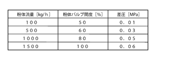
- FIG. 4 is a diagram schematically showing a part of the information in the memory 61.
- the powder flow rate, the opening degree of the powder valve 21, the pressure in the feed tank 11, and the inside of the powder transport pipe 31 are shown.
- this table is referred to as table 1.
- the powder flow rate [kg / h] is specified, the relationship between the opening [%] of the powder valve 21 with respect to the powder flow rate and the differential pressure [MPa] is specified.
- the powder flow rate is 500 [kg / h]
- the opening degree of the powder valve 21 is set to 60 [%]
- the differential pressure is set to 0.03 [MPa].
- a control part controls the opening degree of the valve 21 for powder, and the opening degree of the internal pressure control valve 22 based on the information of the memory 61 which shows the opening degree of the valve 21 for powder as needed.
- the table in the memory 61 is obtained in advance by experiments or the like and recorded in the memory 61.
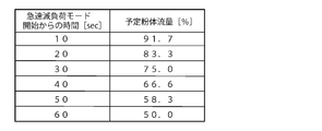
- FIG. 5 is a diagram schematically showing information different from the table 1 of the memory 61.
- FIG. 5 schematically shows a table indicating the relationship between the elapsed time from the start of the rapid load reduction mode and the scheduled powder flow rate at that time when the control unit 60 enters the rapid load reduction mode described later.
- Table 2 This scheduled powder flow rate is the flow rate of the pulverized fuel to be supplied from the feed tank 11 at that time. That is, the powder flow rate is an index in the middle of the rapid load mode so that the powder flow rate decreases to a predetermined amount after a predetermined time from the start of the rapid load reduction mode. As shown in FIG.
- the ratio of the scheduled powder flow rate to the powder flow rate immediately before entering the rapid load reduction mode is specified [%]. Is done. For example, when the elapsed time from the start of the rapid load reduction mode is 20 [sec], the scheduled powder flow rate at that time is 83.3 [%] of the powder flow rate immediately before the rapid load reduction mode is entered. .
- the powder transport pipe 31 is directly or indirectly connected to the combustion furnace 100 that burns pulverized fuel and extracts energy.
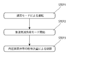
- FIG. 6 is a flowchart showing a method of adjusting the powder flow rate in the rapid load reduction mode.
- the method of supplying the powder flow rate by the powder supply device 1 is STEP1 that operates in the normal operation mode, and the normal operation mode is changed to the rapid load reduction mode, and the internal pressure control valve 22 is in the exhaust state.
- STEP 2 for closing the powder valve to a predetermined opening
- STEP 3 for controlling at least one of the internal pressure control valve and the powder valve based on the information on the powder flow rate.
- the powder supply apparatus 1 operates in the normal operation mode. At this time, the pulverized fuel is already supplied from the pressure equalizing tank 12 into the feed tank 11. Then, the fluidizing gas is introduced into the feed tank 11 from the fluidizing gas pipe 34 through the powder fluidizing portion 54, and the pulverized fuel in the feed tank 11 is fluidized.
- the control unit 60 refers to the table 1 of the memory 61 and the opening degree of the powder valve 21 corresponding to the determined powder flow rate, And the pressure difference between the pressure in the feed tank 11 and the pressure in the carrier gas main pipe 33 is determined. Next, the control unit 60 sends a control signal for determining the opening degree of the powder valve 21 generated based on the information in the memory 61 to the powder valve indicator 41, Based on this control signal, the opening degree of the powder valve 21 is adjusted. Thus, the opening degree of the powder valve 21 is controlled based on the information in the memory 61.
- control unit 60 determines the opening degree of the valve connecting the internal pressure gas supply pipe 32 of the internal pressure control valve 22 and the feed tank 11 based on the information from the table 1 of the memory 61 and the pressure indicators 48 and 49. A control signal is generated, and this control signal is sent to the internal pressure control valve indicator 42.
- the internal pressure control valve indicator 42 adjusts the opening degree of the internal pressure control valve 22 based on this control signal.
- the opening degree of the internal pressure adjusting valve 22 is adjusted, the differential pressure between the pressure in the feed tank 11 and the pressure in the powder transport pipe 31 is set to a predetermined range. In this way, the powder is supplied from the feed tank 11.
- the introduction amount of the refluidizing gas is determined based on the opening degree of the powder valve 21 as described above, as the opening degree of the powder valve 21 increases, the refluidizing gas use amount is increased.
- the opening degree of the valve 27 is reduced, and the amount of refluidized gas introduced is reduced. That is, in this embodiment, the amount of refluidized gas introduced is controlled to be inversely proportional to the opening of the powder valve 21.
- the control unit 60 controls the internal pressure adjustment valve 22 to adjust the pressure difference between the pressure in the feed tank 11 and the pressure in the carrier gas main pipe 33. This is because controlling the internal pressure control valve 22 and adjusting the differential pressure between the pressure in the feed tank 11 and the pressure in the carrier gas main pipe 33 is more effective than adjusting the opening of the powder valve 21. This is because the powder flow rate can be precisely controlled.
- control unit 60 controls the opening degree of the powder valve 21 again, and then controls the internal pressure adjusting valve 22 again, so that the pressure in the feed tank 11 is controlled. And the differential pressure between the pressure in the carrier gas main pipe 33 is adjusted.
- feedback control is performed by a signal including information on the powder flow rate from the powder flow meter 40, and the powder flow rate is accurately adjusted.
- FIG. 7 is a diagram showing temporal changes in the scheduled powder flow rate SV and the powder flow rate PV from the feed tank 11 in the rapid load reduction mode.
- the time when the rapid load reduction mode is set is t1
- the time after the predetermined time has elapsed from the time t1 when the rapid load reduction mode is set is t3
- the time after the predetermined time has elapsed is 50% of the powder flow rate before the rapid load reduction mode is entered.
- control unit 60 when the control unit 60 receives an abnormality signal or the like of the combustion furnace 100, or when a signal indicating an abnormality is input by an operator, the control unit 60 rapidly decreases. It becomes load mode.
- the control unit 60 first sets the internal pressure control valve 22 to the exhaust state. That is, in this embodiment, the opening of the valve connecting the internal pressure gas supply pipe 32 of the internal pressure control valve 22 and the feed tank 11 is reduced, the gas in the feed tank 11 is exhausted, and the pressure in the feed tank is reduced.
- the exhaust valve for reduction is set to a predetermined opening, and the gas in the feed tank 11 is exhausted to the outside of the feed tank 11.
- the control unit 60 controls the powder valve 21 to close to a predetermined opening.
- the period from when the internal pressure adjustment valve 22 is in the exhaust state to when the powder valve 21 is closed to a predetermined opening is not particularly limited, but is, for example, 3 seconds.
- the flow rate of the powder supplied from the feed tank 11 is lowered by setting the internal pressure regulating valve 22 to the exhaust state and closing the powder valve 21 to a predetermined opening degree.
- the internal pressure adjusting valve 22 and the powder valve 21 are controlled without feeding back the information on the powder flow rate from the powder flow meter 40, and the powder flow rate PV after the powder flow rate PV starts to decrease. Is made larger in the negative direction than the average of the inclination of the scheduled powder flow rate SV.
- the internal pressure control valve 22 is exhausted so that the powder flow rate becomes less than a predetermined amount (50% of the powder flow rate before entering the rapid load reduction mode) after a predetermined time (time t3).
- the valve 21 is closed to a predetermined opening.
- Such control of the internal pressure adjusting valve 22 and the powder valve 21 is obtained in advance through experiments or the like.
- the powder valve 21 of the present embodiment can change the hole diameter of the passage port H steplessly and adjust the amount of pulverized fuel supplied from the feed tank 11 steplessly. can do. Therefore, in the emergency load reduction mode, the pressure reduction in the feed tank 11 by the internal pressure adjusting valve 22 and the opening degree of the powder valve 21 can be balanced.
- the internal pressure control valve 22 is in the exhausted state before the powder valve 21 is closed to a predetermined opening when the rapid load reduction mode is set, for the following reason. That is, when the powder valve 21 is closed to a predetermined opening, the pressure in the feed tank 11 tends to increase temporarily. This tendency is attributed to a temporary exhaust delay or the like even when the timing at which the internal pressure control valve 22 is in the exhaust state and the timing at which the powder valve 21 is closed to a predetermined opening degree are simultaneous. Occur. Therefore, in the rapid load reduction mode, the powder flow rate is as high as expected in the early stage of the rapid load reduction mode even though the powder valve 21 is closed to a predetermined opening in order to rapidly reduce the powder flow rate. It may not decrease.
- control unit 60 compares the scheduled powder flow rate SV with the actual powder flow rate PV when in the rapid load reduction mode.
- the expected powder flow rate SV in FIG. 7 is obtained so that the powder flow rate is reduced when the powder flow rate is reduced to a predetermined amount after a predetermined time.
- FIG. 5 shows information on how to reduce the powder flow rate so that the scheduled powder flow rate SV of this embodiment becomes 50.0% of the powder flow rate before the rapid load reduction mode after 60 seconds. It is shown based on the table 2 of the memory 61.
- the actual powder flow rate PV is shown based on information from the powder flow meter 40.
- the flow rate of the powder supplied from the feed tank 11 decreases. However, as shown in FIG. 7, it decreases rapidly due to the time required for the operation of the internal pressure control valve 22 and the powder valve 21 and the temporary delay after the internal pressure control valve 22 and the powder valve 21 operate.
- the powder flow rate PV does not decrease immediately after the load mode is set, but the powder flow rate PV decreases after a predetermined time. For this reason, the powder flow rate PV from the feed tank 11 changes more than the scheduled powder flow rate SV for a while after the rapid load reduction mode is set.
- the control unit 60 controls at least one of the internal pressure control valve 22 and the powder valve 21 so that the powder flow rate PV becomes the planned powder flow rate SV. Control is performed based on information relating to the powder flow rate from the powder flow meter 40. That is, the control unit 60 feedback-controls at least one of the internal pressure control valve 22 and the powder valve 21 using information related to the powder flow rate from the powder flow meter 40, so that the powder flow rate PV becomes the expected powder. Approach the body SV.
- the control unit 60 is to control the internal pressure control valve 22.
- the opening degree is controlled so that the powder valve 21 is opened.
- adjusting the differential pressure between the pressure in the feed tank 11 and the pressure in the carrier gas main pipe 33 is more effective than adjusting the opening of the powder valve 21. Since precise control is possible, it is preferable to control the internal pressure control valve 22 with the opening of the powder valve 21 fixed.
- the powder amount is set to a predetermined amount, and the rapid load reduction mode ends.
- the flow rate of the powder supplied to the combustion furnace 100 is rapidly reduced.
- control for increasing the powder flow rate is not performed again, and normal control in which the powder flow rate is set to a predetermined amount is continued until an instruction is given.
- the internal pressure regulating valve 22 is brought into the exhaust state, whereby the inside of the feed tank 11 is decompressed, and the feed tank 11 The pressure difference between the internal pressure and the pressure in the powder transport pipe is reduced, and in addition, the powder valve 21 is closed to a predetermined opening. Therefore, the flow rate of the powder supplied from the feed tank 11 can be rapidly reduced.
- the internal pressure control valve 22 and the powder flow rate are reduced.
- At least one of the valves 21 is feedback-controlled based on information from the powder flow meter 40. For this reason, it is possible to suppress the powder flow rate from undershooting at the end of the rapid load reduction mode. Thus, in the powder supply apparatus 1 of the present invention, it is realized that the underflow of the powder flow rate is suppressed while the powder flow rate is rapidly reduced.
- the scheduled powder flow rate is determined based on the powder flow rate immediately before the rapid load reduction mode is entered. Therefore, it is possible to obtain an appropriate scheduled powder flow rate according to the situation where the powder is being supplied, and it is possible to rapidly reduce the powder flow rate without difficulty.
- control unit 60 may control only the powder valve 21, and the internal pressure adjusting valve 22 and Both of the powder valves 21 may be controlled.
- the internal pressure control valve 22 and the powder valve 21 are controlled based on the powder flow rate information from the powder flow meter 40.
- the present invention is not limited to this, and the powder flow rate may be calculated by the control unit 60 based on information from the weight indicating controller 46, and the internal pressure control valve 22 and the powder valve 21 may be controlled. .
- valve 21 another form of valve may be used as the powder valve 21.
- a ball valve in which a through hole having a predetermined inner diameter is formed in a sphere may be used.
- the scheduled powder flow rate is determined based on the powder flow rate immediately before the rapid load reduction mode is entered, but the present invention is not limited to this.
- the scheduled powder flow rate in the rapid load reduction mode may be a flow rate that is not based on the powder flow rate immediately before entering the rapid load reduction mode.
- the scheduled powder flow rate in the table 2 of the memory 61 is an absolute amount indicated by [kg / h].
- the pulverized fuel in the feed tank is fluidized by the fluidizing gas, and the pulverized fuel is re-fluidized in the powder transport pipe 31.
- refluidization is not essential.
- the powder supply apparatus which supplies the powder which is powder fuels, such as pulverized coal, was demonstrated, this invention is not limited to this, The other powder which is not a powder fuel is supplied.
- the present invention can also be applied to a powder supply apparatus.
- a powder supply apparatus and a powder supply method capable of suppressing the occurrence of undershoot of the powder flow rate while rapidly reducing the powder flow rate.
- the present invention can be applied to a powder supply device for supplying a pulverized fuel to a combustion furnace used in a blast furnace facility, a thermal power plant or the like, and other powder supply devices.
Landscapes
- Engineering & Computer Science (AREA)
- Chemical & Material Sciences (AREA)
- Combustion & Propulsion (AREA)
- Mechanical Engineering (AREA)
- General Engineering & Computer Science (AREA)
- Air Transport Of Granular Materials (AREA)
- Blast Furnaces (AREA)
- Manufacture Of Iron (AREA)
Abstract
Description
まず、粉体供給装置1は、通常運転モードで運転をする。このとき、フィードタンク11内には、既に、均圧タンク12から粉体燃料が供給されている。そして、流動化ガスが、流動化ガス管34から粉体流動化部54を介して、フィードタンク11内に導入され、フィードタンク11内の粉体燃料は流動化されている。 <STEP1>
First, the
図7は、急速減負荷モードにおける予定粉体流量SVと、フィードタンク11からの粉体流量PVの時間的な変化を示す図である。本実施形態では、図7に示すように、急速減負荷モードとなる時刻がt1とされ、急速減負荷モードとなる時刻t1から所定時間経過後の時刻がt3とされ、所定時間経過後の時刻t3において所定量となる粉体流量が、急速減負荷モードとなる前の粉体流量の50%とされる。 <STEP2>
FIG. 7 is a diagram showing temporal changes in the scheduled powder flow rate SV and the powder flow rate PV from the
粉体流量PVが予定粉体SVよりも少なくなり次第、制御部60は、内圧調節弁22及び粉体用バルブ21の少なくとも一方を、粉体流量PVが予定粉体流量SVとなるように、粉体流量計40からの粉体流量に係る情報に基づいて制御する。つまり、制御部60は、粉体流量計40からの粉体流量に係る情報を用いて、内圧調節弁22及び粉体用バルブ21の少なくとも一方をフィードバック制御して、粉体流量PVが予定粉体SVに近づくようにする。時刻t2の経過直後においては、フィードタンク11からの粉体流量PVが、予定粉体流量SVよりも少ないため、この時点において、制御部60は、内圧調節弁22を制御する場合であれば、例えば、フィードタンク11からの排気が少なくなるように制御し、粉体用バルブ21を制御する場合であれば、粉体用バルブ21が開くように開度を制御する。なお、上述のように、フィードタンク11内の圧力とキャリアガス本管33内の圧力との差圧を調整する方が、粉体用バルブ21の開度を調節するよりも、粉体流量の緻密な制御ができるため、粉体用バルブ21の開度を固定として、内圧調節弁22を制御する方が好ましい。 <STEP3>
As soon as the powder flow rate PV becomes smaller than the planned powder SV, the
11・・・フィードタンク
12・・・均圧タンク
21・・・粉体用バルブ
22・・・内圧調節弁
24・・・流動化ガス用バルブ
25・・・粉体供給用弁
27・・・再流動化ガス用バルブ
30・・・ガス発生装置
31・・・粉体輸送配管
32・・・内圧用ガス供給配管
33・・・キャリアガス本管
34・・・流動化ガス管
35・・・粉体供給配管
37・・・再流動化ガス管
40・・・粉体流量計
41・・・粉体用バルブ指示計
42・・・内圧調節弁指示計
43・・・圧力指示計
44・・・流動化ガス用バルブ指示計
45・・・ロードセル
46・・・重量指示調節計
47・・・再流動化ガス用バルブ指示計
48・・・圧力指示計
49・・・圧力指示計
54・・・粉体流動化部
57・・・粉体再流動化部
60・・・制御部
61・・・メモリ
100・・・燃焼炉 DESCRIPTION OF
Claims (8)
- フィードタンク内の粉体を前記フィードタンクに接続された粉体輸送配管から前記フィードタンク外に供給する粉体供給装置であって、
前記フィードタンクに接続され、前記フィードタンク内の圧力を調節する内圧調節弁と、
前記粉体輸送配管に接続される粉体用バルブと、
前記内圧調節弁及び前記粉体用バルブを制御する制御部と、
を備え、
前記制御部は、
前記フィードタンク外に供給される粉体流量を所定時間後に所定量まで減らす急速減負荷モードにおいて、
前記粉体流量が前記所定時間後に前記所定量よりも少なくなるように前記内圧調節弁を前記フィードタンク内の圧力を減らす排気状態とすると共に、前記粉体用バルブを所定の開度まで閉じ、
前記粉体流量が前記所定時間後に前記所定量となるための前記所定時間経過前における予定粉体流量よりも、前記粉体流量が少なくなり次第、前記内圧調節弁及び前記粉体用バルブの少なくとも一方を、前記粉体流量が前記予定粉体流量となるように、前記粉体流量の情報に基づいて制御する
ことを特徴とする粉体供給装置。 A powder supply device for supplying powder in a feed tank to the outside of the feed tank from a powder transport pipe connected to the feed tank,
An internal pressure regulating valve connected to the feed tank and regulating the pressure in the feed tank;
A powder valve connected to the powder transport pipe;
A control unit for controlling the internal pressure control valve and the powder valve;
With
The controller is
In the rapid load reduction mode in which the powder flow rate supplied to the outside of the feed tank is reduced to a predetermined amount after a predetermined time,
The powder flow rate is set to an exhaust state in which the pressure in the feed tank is reduced so that the powder flow rate becomes less than the predetermined amount after the predetermined time, and the powder valve is closed to a predetermined opening degree.
As soon as the powder flow rate becomes lower than the scheduled powder flow rate before the predetermined time has elapsed for the powder flow rate to reach the predetermined amount after the predetermined time, at least one of the internal pressure control valve and the powder valve One side is controlled based on the information on the powder flow rate so that the powder flow rate becomes the scheduled powder flow rate. - 前記予定粉体流量は、前記急速減負荷モードとなる直前の前記粉体流量に基づいて定められることを特徴とする請求項1に記載の粉体供給装置。 The powder supply apparatus according to claim 1, wherein the scheduled powder flow rate is determined based on the powder flow rate immediately before the rapid load reduction mode is entered.
- 前記粉体輸送配管には、粉体流量計が接続されており、
前記制御部は、前記予定粉体流量よりも前記粉体流量が少なくなり次第、前記粉体流量計からの情報に基づいて、前記内圧調節弁及び前記粉体用バルブを制御する
ことを特徴とする請求項1または2に記載の粉体供給装置。 A powder flow meter is connected to the powder transport pipe,
The control unit controls the internal pressure control valve and the powder valve based on information from the powder flow meter as soon as the powder flow rate becomes smaller than the scheduled powder flow rate. The powder supply apparatus according to claim 1 or 2. - 前記制御部は、前記粉体用バルブを所定の開度まで閉じる前に、前記内圧調節弁を前記排気状態とすることを特徴とする請求項1から3のいずれか1項に記載の粉体供給装置。 4. The powder according to claim 1, wherein the control unit sets the internal pressure regulating valve to the exhaust state before closing the powder valve to a predetermined opening degree. 5. Feeding device.
- フィードタンク内の粉体を前記フィードタンクに接続された粉体輸送配管から前記フィードタンク外に供給する粉体供給方法であって、
前記フィードタンク外に供給される粉体流量を所定時間後に所定量まで減らす急速減負荷モードにおいて、
前記粉体流量が前記所定時間後に前記所定量よりも少なくなるように前記フィードタンクに接続される内圧調節弁が前記フィードタンク内の圧力を減らす排気状態とされると共に、前記粉体輸送配管に接続される粉体用バルブが所定の開度まで閉じられ、
前記粉体流量が前記所定時間後に前記所定量となるための前記所定時間経過前における予定粉体流量よりも、前記粉体流量が少なくなり次第、前記内圧調節弁及び前記粉体用バルブの少なくとも一方が、前記粉体流量が前記予定粉体流量となるように、前記粉体流量の情報に基づいて調節される
ことを特徴とする粉体供給方法。 A powder supply method for supplying powder in a feed tank to the outside of the feed tank from a powder transport pipe connected to the feed tank,
In the rapid load reduction mode in which the powder flow rate supplied to the outside of the feed tank is reduced to a predetermined amount after a predetermined time,
An internal pressure control valve connected to the feed tank is in an exhaust state to reduce the pressure in the feed tank so that the powder flow rate becomes less than the predetermined amount after the predetermined time, and The connected powder valve is closed to a predetermined opening,
As soon as the powder flow rate becomes lower than the scheduled powder flow rate before the predetermined time has elapsed for the powder flow rate to reach the predetermined amount after the predetermined time, at least one of the internal pressure control valve and the powder valve One of the powder supply methods is characterized in that the powder flow rate is adjusted based on the information on the powder flow rate so that the powder flow rate becomes the planned powder flow rate. - 前記予定粉体流量は、前記急速減負荷モードとなる直前の前記粉体流量に基づいて定められることを特徴とする請求項5に記載の粉体供給方法。 6. The powder supply method according to claim 5, wherein the scheduled powder flow rate is determined based on the powder flow rate immediately before the rapid load reduction mode is entered.
- 前記予定粉体流量よりも前記粉体流量が少なくなり次第、前記粉体輸送配管に接続される粉体流量計からの情報に基づいて、前記内圧調節弁及び前記粉体用バルブは調節される
ことを特徴とする請求項5または6に記載の粉体供給方法。 As soon as the powder flow rate becomes smaller than the scheduled powder flow rate, the internal pressure control valve and the powder valve are adjusted based on information from a powder flow meter connected to the powder transport pipe. The powder supply method according to claim 5 or 6, wherein: - 前記粉体用バルブが所定の開度まで閉じられる前に、前記内圧調節弁が前記排気状態とされることを特徴とする請求項5から7のいずれか1項に記載の粉体供給方法。 The powder supply method according to any one of claims 5 to 7, wherein the internal pressure control valve is brought into the exhaust state before the powder valve is closed to a predetermined opening degree.
Priority Applications (4)
| Application Number | Priority Date | Filing Date | Title |
|---|---|---|---|
| CN201380014290.9A CN104169198B (en) | 2012-03-14 | 2013-02-12 | powder supply device and powder supply method |
| JP2013525481A JP5324729B1 (en) | 2012-03-14 | 2013-02-12 | Powder supply apparatus and powder supply method |
| DE112013001463.7T DE112013001463T5 (en) | 2012-03-14 | 2013-02-12 | Powder feeder and powder feed method |
| US14/382,157 US20150021358A1 (en) | 2012-03-14 | 2013-02-12 | Powder supply device and powder supply method |
Applications Claiming Priority (2)
| Application Number | Priority Date | Filing Date | Title |
|---|---|---|---|
| JP2012-056870 | 2012-03-14 | ||
| JP2012056870 | 2012-03-14 |
Publications (1)
| Publication Number | Publication Date |
|---|---|
| WO2013136893A1 true WO2013136893A1 (en) | 2013-09-19 |
Family
ID=49160812
Family Applications (1)
| Application Number | Title | Priority Date | Filing Date |
|---|---|---|---|
| PCT/JP2013/053250 WO2013136893A1 (en) | 2012-03-14 | 2013-02-12 | Powder supply apparatus and powder supply method |
Country Status (5)
| Country | Link |
|---|---|
| US (1) | US20150021358A1 (en) |
| JP (1) | JP5324729B1 (en) |
| CN (1) | CN104169198B (en) |
| DE (1) | DE112013001463T5 (en) |
| WO (1) | WO2013136893A1 (en) |
Families Citing this family (8)
| Publication number | Priority date | Publication date | Assignee | Title |
|---|---|---|---|---|
| JP5520244B2 (en) * | 2011-02-21 | 2014-06-11 | ダイヤモンドエンジニアリング株式会社 | Powder supply apparatus and powder supply method |
| WO2013035701A1 (en) * | 2011-09-05 | 2013-03-14 | ダイヤモンドエンジニアリング株式会社 | Powder supply device and powder supply method |
| CN103906693B (en) * | 2011-10-25 | 2016-02-17 | 钻石工程株式会社 | powder supply device and powder supply method |
| EP2787402B1 (en) * | 2013-04-04 | 2017-02-15 | Fast&Fluid Management B.V. | Fluid dispenser and method for dispensing fluids |
| CN104874502B (en) * | 2015-06-04 | 2017-08-22 | 杭州特诚基础工程科技有限公司 | A kind of feeder apparatus for realizing the control of pulvis automatic ration |
| US10412369B2 (en) | 2015-07-31 | 2019-09-10 | Dell Products, Lp | Method and apparatus for compensating for camera error in a multi-camera stereo camera system |
| WO2017201293A1 (en) * | 2016-05-18 | 2017-11-23 | Graco Minnesota Inc. | Vapor abrasive blasting system with closed loop flow control |
| CN114985773B (en) * | 2022-03-15 | 2023-07-07 | 南京辉锐光电科技有限公司 | Powder mixing and feeding device of laser material adding equipment and laser material adding equipment |
Citations (3)
| Publication number | Priority date | Publication date | Assignee | Title |
|---|---|---|---|---|
| JPH03297729A (en) * | 1990-04-13 | 1991-12-27 | Nippon Alum Co Ltd | Low speed and high density transportation method for bulk material |
| JPH06115690A (en) * | 1991-07-16 | 1994-04-26 | Daiyamondo Eng Kk | Pulverized coal discharge quantity control device |
| JP2003302281A (en) * | 2002-04-10 | 2003-10-24 | Aisan Ind Co Ltd | Powder feeder and power feeding method |
Family Cites Families (1)
| Publication number | Priority date | Publication date | Assignee | Title |
|---|---|---|---|---|
| JPH08152128A (en) * | 1994-11-29 | 1996-06-11 | Mitsubishi Heavy Ind Ltd | Crushed coal supply device |
-
2013
- 2013-02-12 JP JP2013525481A patent/JP5324729B1/en active Active
- 2013-02-12 US US14/382,157 patent/US20150021358A1/en not_active Abandoned
- 2013-02-12 DE DE112013001463.7T patent/DE112013001463T5/en active Pending
- 2013-02-12 WO PCT/JP2013/053250 patent/WO2013136893A1/en active Application Filing
- 2013-02-12 CN CN201380014290.9A patent/CN104169198B/en active Active
Patent Citations (3)
| Publication number | Priority date | Publication date | Assignee | Title |
|---|---|---|---|---|
| JPH03297729A (en) * | 1990-04-13 | 1991-12-27 | Nippon Alum Co Ltd | Low speed and high density transportation method for bulk material |
| JPH06115690A (en) * | 1991-07-16 | 1994-04-26 | Daiyamondo Eng Kk | Pulverized coal discharge quantity control device |
| JP2003302281A (en) * | 2002-04-10 | 2003-10-24 | Aisan Ind Co Ltd | Powder feeder and power feeding method |
Also Published As
| Publication number | Publication date |
|---|---|
| JPWO2013136893A1 (en) | 2015-08-03 |
| US20150021358A1 (en) | 2015-01-22 |
| CN104169198B (en) | 2016-03-30 |
| DE112013001463T5 (en) | 2014-12-04 |
| CN104169198A (en) | 2014-11-26 |
| JP5324729B1 (en) | 2013-10-23 |
Similar Documents
| Publication | Publication Date | Title |
|---|---|---|
| JP5324729B1 (en) | Powder supply apparatus and powder supply method | |
| JP5520244B2 (en) | Powder supply apparatus and powder supply method | |
| WO2012115061A1 (en) | Powder supply apparatus and powder supply method | |
| JP5160292B2 (en) | Pressurized powder supply apparatus and operation method thereof | |
| JP5087879B2 (en) | Powder injection method | |
| JP5255734B1 (en) | Powder supply apparatus and powder supply method | |
| US9296570B2 (en) | Powder supply device and powder supply method | |
| JP5738046B2 (en) | Coal gasification coal transfer system | |
| JP6139763B1 (en) | Powder parallel blowing system and powder parallel blowing method | |
| JP4537953B2 (en) | Control method of pulverized coal injection to blast furnace and its control device | |
| JP4448499B2 (en) | Control method of pulverized coal injection into blast furnace | |
| JP2014088219A (en) | Powder supply device and powder supply method | |
| WO2012115060A1 (en) | Powder supply apparatus and powder supply method | |
| JP2012086164A (en) | Device and method for producing mixed gas production | |
| JPH0711313A (en) | Control method for blowing of pulverized coal | |
| JP2014088220A (en) | Powder supply device and powder supply method | |
| CN111690442A (en) | Pulverized coal flow control method | |
| JP2007205224A (en) | Fuel gas pressure control device and fuel gas pressure control method for dual fuel combustion gas turbine | |
| JP6812071B2 (en) | Powder parallel blowing system and powder parallel blowing method | |
| CN100557041C (en) | The high-temperature ring annealing furnace protective gas proportioning cascade feedback control method | |
| CN103740875B (en) | A kind of blast furnace injection device and blowing method | |
| JPS59164820A (en) | Fuel system control of coal-fired power plant | |
| JP2001220016A (en) | Control method for transporting speed of powder and grain and transporting device | |
| JPH0117968B2 (en) | ||
| JP2003056809A (en) | Pressurized fluidized bed boiler and method for controlling amount of combustion air |
Legal Events
| Date | Code | Title | Description |
|---|---|---|---|
| WWE | Wipo information: entry into national phase |
Ref document number: 201380014290.9 Country of ref document: CN |
|
| ENP | Entry into the national phase |
Ref document number: 2013525481 Country of ref document: JP Kind code of ref document: A |
|
| 121 | Ep: the epo has been informed by wipo that ep was designated in this application |
Ref document number: 13761917 Country of ref document: EP Kind code of ref document: A1 |
|
| WWE | Wipo information: entry into national phase |
Ref document number: 14382157 Country of ref document: US |
|
| WWE | Wipo information: entry into national phase |
Ref document number: 1120130014637 Country of ref document: DE Ref document number: 112013001463 Country of ref document: DE |
|
| 122 | Ep: pct application non-entry in european phase |
Ref document number: 13761917 Country of ref document: EP Kind code of ref document: A1 |