WO2013129504A1 - Procédé de commande de communication, terminal utilisateur et station de base - Google Patents
Procédé de commande de communication, terminal utilisateur et station de base Download PDFInfo
- Publication number
- WO2013129504A1 WO2013129504A1 PCT/JP2013/055200 JP2013055200W WO2013129504A1 WO 2013129504 A1 WO2013129504 A1 WO 2013129504A1 JP 2013055200 W JP2013055200 W JP 2013055200W WO 2013129504 A1 WO2013129504 A1 WO 2013129504A1
- Authority
- WO
- WIPO (PCT)
- Prior art keywords
- precoder matrix
- fed back
- information
- correction value
- user terminal
- Prior art date
Links
Images


Classifications
-
- H—ELECTRICITY
- H04—ELECTRIC COMMUNICATION TECHNIQUE
- H04W—WIRELESS COMMUNICATION NETWORKS
- H04W16/00—Network planning, e.g. coverage or traffic planning tools; Network deployment, e.g. resource partitioning or cells structures
- H04W16/24—Cell structures
- H04W16/28—Cell structures using beam steering
-
- H—ELECTRICITY
- H04—ELECTRIC COMMUNICATION TECHNIQUE
- H04B—TRANSMISSION
- H04B7/00—Radio transmission systems, i.e. using radiation field
- H04B7/02—Diversity systems; Multi-antenna system, i.e. transmission or reception using multiple antennas
- H04B7/04—Diversity systems; Multi-antenna system, i.e. transmission or reception using multiple antennas using two or more spaced independent antennas
- H04B7/0413—MIMO systems
- H04B7/0417—Feedback systems
-
- H—ELECTRICITY
- H04—ELECTRIC COMMUNICATION TECHNIQUE
- H04B—TRANSMISSION
- H04B7/00—Radio transmission systems, i.e. using radiation field
- H04B7/02—Diversity systems; Multi-antenna system, i.e. transmission or reception using multiple antennas
- H04B7/04—Diversity systems; Multi-antenna system, i.e. transmission or reception using multiple antennas using two or more spaced independent antennas
- H04B7/0413—MIMO systems
- H04B7/0456—Selection of precoding matrices or codebooks, e.g. using matrices antenna weighting
-
- H—ELECTRICITY
- H04—ELECTRIC COMMUNICATION TECHNIQUE
- H04B—TRANSMISSION
- H04B7/00—Radio transmission systems, i.e. using radiation field
- H04B7/02—Diversity systems; Multi-antenna system, i.e. transmission or reception using multiple antennas
- H04B7/04—Diversity systems; Multi-antenna system, i.e. transmission or reception using multiple antennas using two or more spaced independent antennas
- H04B7/06—Diversity systems; Multi-antenna system, i.e. transmission or reception using multiple antennas using two or more spaced independent antennas at the transmitting station
- H04B7/0613—Diversity systems; Multi-antenna system, i.e. transmission or reception using multiple antennas using two or more spaced independent antennas at the transmitting station using simultaneous transmission
- H04B7/0615—Diversity systems; Multi-antenna system, i.e. transmission or reception using multiple antennas using two or more spaced independent antennas at the transmitting station using simultaneous transmission of weighted versions of same signal
- H04B7/0619—Diversity systems; Multi-antenna system, i.e. transmission or reception using multiple antennas using two or more spaced independent antennas at the transmitting station using simultaneous transmission of weighted versions of same signal using feedback from receiving side
- H04B7/0621—Feedback content
- H04B7/0632—Channel quality parameters, e.g. channel quality indicator [CQI]
-
- H—ELECTRICITY
- H04—ELECTRIC COMMUNICATION TECHNIQUE
- H04B—TRANSMISSION
- H04B7/00—Radio transmission systems, i.e. using radiation field
- H04B7/02—Diversity systems; Multi-antenna system, i.e. transmission or reception using multiple antennas
- H04B7/04—Diversity systems; Multi-antenna system, i.e. transmission or reception using multiple antennas using two or more spaced independent antennas
- H04B7/06—Diversity systems; Multi-antenna system, i.e. transmission or reception using multiple antennas using two or more spaced independent antennas at the transmitting station
- H04B7/0613—Diversity systems; Multi-antenna system, i.e. transmission or reception using multiple antennas using two or more spaced independent antennas at the transmitting station using simultaneous transmission
- H04B7/0615—Diversity systems; Multi-antenna system, i.e. transmission or reception using multiple antennas using two or more spaced independent antennas at the transmitting station using simultaneous transmission of weighted versions of same signal
- H04B7/0619—Diversity systems; Multi-antenna system, i.e. transmission or reception using multiple antennas using two or more spaced independent antennas at the transmitting station using simultaneous transmission of weighted versions of same signal using feedback from receiving side
- H04B7/0636—Feedback format
- H04B7/0639—Using selective indices, e.g. of a codebook, e.g. pre-distortion matrix index [PMI] or for beam selection
-
- H—ELECTRICITY
- H04—ELECTRIC COMMUNICATION TECHNIQUE
- H04B—TRANSMISSION
- H04B7/00—Radio transmission systems, i.e. using radiation field
- H04B7/02—Diversity systems; Multi-antenna system, i.e. transmission or reception using multiple antennas
- H04B7/04—Diversity systems; Multi-antenna system, i.e. transmission or reception using multiple antennas using two or more spaced independent antennas
- H04B7/06—Diversity systems; Multi-antenna system, i.e. transmission or reception using multiple antennas using two or more spaced independent antennas at the transmitting station
- H04B7/0613—Diversity systems; Multi-antenna system, i.e. transmission or reception using multiple antennas using two or more spaced independent antennas at the transmitting station using simultaneous transmission
- H04B7/0615—Diversity systems; Multi-antenna system, i.e. transmission or reception using multiple antennas using two or more spaced independent antennas at the transmitting station using simultaneous transmission of weighted versions of same signal
- H04B7/0619—Diversity systems; Multi-antenna system, i.e. transmission or reception using multiple antennas using two or more spaced independent antennas at the transmitting station using simultaneous transmission of weighted versions of same signal using feedback from receiving side
- H04B7/0636—Feedback format
- H04B7/0641—Differential feedback
-
- H—ELECTRICITY
- H04—ELECTRIC COMMUNICATION TECHNIQUE
- H04B—TRANSMISSION
- H04B7/00—Radio transmission systems, i.e. using radiation field
- H04B7/02—Diversity systems; Multi-antenna system, i.e. transmission or reception using multiple antennas
- H04B7/04—Diversity systems; Multi-antenna system, i.e. transmission or reception using multiple antennas using two or more spaced independent antennas
- H04B7/06—Diversity systems; Multi-antenna system, i.e. transmission or reception using multiple antennas using two or more spaced independent antennas at the transmitting station
- H04B7/0613—Diversity systems; Multi-antenna system, i.e. transmission or reception using multiple antennas using two or more spaced independent antennas at the transmitting station using simultaneous transmission
- H04B7/0615—Diversity systems; Multi-antenna system, i.e. transmission or reception using multiple antennas using two or more spaced independent antennas at the transmitting station using simultaneous transmission of weighted versions of same signal
- H04B7/0619—Diversity systems; Multi-antenna system, i.e. transmission or reception using multiple antennas using two or more spaced independent antennas at the transmitting station using simultaneous transmission of weighted versions of same signal using feedback from receiving side
- H04B7/0652—Feedback error handling
-
- H—ELECTRICITY
- H04—ELECTRIC COMMUNICATION TECHNIQUE
- H04L—TRANSMISSION OF DIGITAL INFORMATION, e.g. TELEGRAPHIC COMMUNICATION
- H04L1/00—Arrangements for detecting or preventing errors in the information received
- H04L1/0001—Systems modifying transmission characteristics according to link quality, e.g. power backoff
- H04L1/0023—Systems modifying transmission characteristics according to link quality, e.g. power backoff characterised by the signalling
- H04L1/0026—Transmission of channel quality indication
-
- H—ELECTRICITY
- H04—ELECTRIC COMMUNICATION TECHNIQUE
- H04L—TRANSMISSION OF DIGITAL INFORMATION, e.g. TELEGRAPHIC COMMUNICATION
- H04L1/00—Arrangements for detecting or preventing errors in the information received
- H04L1/0001—Systems modifying transmission characteristics according to link quality, e.g. power backoff
- H04L1/0023—Systems modifying transmission characteristics according to link quality, e.g. power backoff characterised by the signalling
- H04L1/0028—Formatting
- H04L1/0031—Multiple signaling transmission
-
- H—ELECTRICITY
- H04—ELECTRIC COMMUNICATION TECHNIQUE
- H04B—TRANSMISSION
- H04B7/00—Radio transmission systems, i.e. using radiation field
- H04B7/02—Diversity systems; Multi-antenna system, i.e. transmission or reception using multiple antennas
- H04B7/022—Site diversity; Macro-diversity
- H04B7/024—Co-operative use of antennas of several sites, e.g. in co-ordinated multipoint or co-operative multiple-input multiple-output [MIMO] systems
-
- H—ELECTRICITY
- H04—ELECTRIC COMMUNICATION TECHNIQUE
- H04B—TRANSMISSION
- H04B7/00—Radio transmission systems, i.e. using radiation field
- H04B7/02—Diversity systems; Multi-antenna system, i.e. transmission or reception using multiple antennas
- H04B7/04—Diversity systems; Multi-antenna system, i.e. transmission or reception using multiple antennas using two or more spaced independent antennas
- H04B7/0413—MIMO systems
- H04B7/0452—Multi-user MIMO systems
-
- H—ELECTRICITY
- H04—ELECTRIC COMMUNICATION TECHNIQUE
- H04B—TRANSMISSION
- H04B7/00—Radio transmission systems, i.e. using radiation field
- H04B7/02—Diversity systems; Multi-antenna system, i.e. transmission or reception using multiple antennas
- H04B7/04—Diversity systems; Multi-antenna system, i.e. transmission or reception using multiple antennas using two or more spaced independent antennas
- H04B7/06—Diversity systems; Multi-antenna system, i.e. transmission or reception using multiple antennas using two or more spaced independent antennas at the transmitting station
- H04B7/0613—Diversity systems; Multi-antenna system, i.e. transmission or reception using multiple antennas using two or more spaced independent antennas at the transmitting station using simultaneous transmission
- H04B7/0615—Diversity systems; Multi-antenna system, i.e. transmission or reception using multiple antennas using two or more spaced independent antennas at the transmitting station using simultaneous transmission of weighted versions of same signal
- H04B7/0619—Diversity systems; Multi-antenna system, i.e. transmission or reception using multiple antennas using two or more spaced independent antennas at the transmitting station using simultaneous transmission of weighted versions of same signal using feedback from receiving side
- H04B7/0636—Feedback format
- H04B7/0643—Feedback on request
-
- H—ELECTRICITY
- H04—ELECTRIC COMMUNICATION TECHNIQUE
- H04B—TRANSMISSION
- H04B7/00—Radio transmission systems, i.e. using radiation field
- H04B7/02—Diversity systems; Multi-antenna system, i.e. transmission or reception using multiple antennas
- H04B7/04—Diversity systems; Multi-antenna system, i.e. transmission or reception using multiple antennas using two or more spaced independent antennas
- H04B7/06—Diversity systems; Multi-antenna system, i.e. transmission or reception using multiple antennas using two or more spaced independent antennas at the transmitting station
- H04B7/0613—Diversity systems; Multi-antenna system, i.e. transmission or reception using multiple antennas using two or more spaced independent antennas at the transmitting station using simultaneous transmission
- H04B7/0615—Diversity systems; Multi-antenna system, i.e. transmission or reception using multiple antennas using two or more spaced independent antennas at the transmitting station using simultaneous transmission of weighted versions of same signal
- H04B7/0665—Feed forward of transmit weights to the receiver
-
- H—ELECTRICITY
- H04—ELECTRIC COMMUNICATION TECHNIQUE
- H04L—TRANSMISSION OF DIGITAL INFORMATION, e.g. TELEGRAPHIC COMMUNICATION
- H04L27/00—Modulated-carrier systems
- H04L27/0008—Modulated-carrier systems arrangements for allowing a transmitter or receiver to use more than one type of modulation
Definitions
- the present invention relates to a communication control method for handling precoder matrix information, a user terminal, and a base station.
- 3GPP 3rd Generation Partnership Project
- a standardization project for mobile communication systems supports multi-antenna transmission technology in which a base station directs a beam to a specific user terminal and directs a null to another user terminal.
- a base station directs a beam to a specific user terminal and directs a null to another user terminal.
- each of a plurality of user terminals feeds back to the base station precoder matrix information indicating a precoder matrix preferable for use in the downlink.
- the base station precodes the downlink signal using a precoder matrix based on precoder matrix information fed back for each user terminal. Then, the base station transmits the precoded downlink signal via a plurality of antenna ports (a plurality of feeding points).
- the precoder matrix is composed of a plurality of precoder matrix elements (a plurality of weights) corresponding to a plurality of antenna ports.
- the base station directs the beam toward the specific user terminal and accurately directs the null to other user terminals. There is a problem that is difficult.
- an object of the present invention is to provide a communication control method, a user terminal, and a base station in which the base station can direct the beam / null appropriately to the user terminal.
- the present invention has the following features.
- the communication control method of the present invention includes a base station that transmits a downlink signal precoded using a precoder matrix via a plurality of antenna ports, and precoder matrix information indicating a precoder matrix that is preferable for use in the downlink.
- the communication control method further includes a step B of instructing from the base station to notify the correction value information.
- the user terminal responds to an instruction from the base station in the step B.
- the correction value information may be fed back.
- step A each time the user terminal feeds back the correction value information, the user terminal may increase the resolution of the correction value information to be fed back.
- the correction value information may include information indicating the resolution of the correction value information.
- the communication control method further includes a step C of accumulating the correction value information every time the base station receives the correction value information when the correction value information is fed back multiple times from the user terminal. May be.
- the base station applies a precoder to transmit a downlink signal according to the precoder matrix information fed back from the user terminal and the accumulated correction value information obtained in the step C.
- a matrix may be determined.
- the communication control method may further include a step E of resetting the accumulated correction value information obtained in the step C when the precoder matrix information to be fed back is changed.
- the communication control method further includes a step F of feeding back channel quality information indicating a modulation scheme / coding rate preferable for use in downlink from the user terminal to the base station, and in the step F, When feeding back the correction value information, the user terminal may correct the channel quality information to be fed back.
- the precoder matrix information may indicate a precoder matrix in which null is directed toward the user terminal.
- the precoder matrix information may indicate a precoder matrix in which a beam is directed toward the user terminal.
- the user terminal of the present invention feeds back precoder matrix information indicating a precoder matrix preferable for use in the downlink to a base station that transmits a downlink signal precoded using the precoder matrix via a plurality of antenna ports.
- a control unit that feeds back correction value information for correcting the precoder matrix information to the base station when the precoder matrix information is fed back or after the precoder matrix information is fed back. It is characterized by having.
- a base station of the present invention is a base station that transmits a downlink signal precoded using a precoder matrix via a plurality of antenna ports, and receives a precoder matrix information fed back from a user terminal. And a second receiving unit that receives correction value information fed back from the user terminal when the precoder matrix information is fed back or after the precoder matrix information is fed back, and the precoder matrix
- the information indicates a precoder matrix preferable for use in downlink, and the correction value information is information for correcting the precoder matrix information.
- the communication control method includes a base station that transmits a downlink signal precoded using a precoder matrix via a plurality of antenna ports, and precoder matrix information indicating a precoder matrix preferable for use in downlink.
- the present invention is applied to a mobile communication system having a user terminal that feeds back to a base station.
- correction value information for correcting the precoder matrix information is transmitted from the user terminal to the base station.
- the base station can correct the fed back precoder matrix information (specifically, the precoder matrix indicated by the precoder matrix information) using the feedback correction value information.
- Beam / null can be directed with high accuracy.
- FIG. 1 is a configuration diagram of an LTE system.
- the LTE system 1 includes a UE (User Equipment), an E-UTRAN (Evolved-UMTS Terrestrial Radio Access Network), and an EPC (Evolved Packet Core).
- UE User Equipment
- E-UTRAN Evolved-UMTS Terrestrial Radio Access Network
- EPC Evolved Packet Core
- the UE is a mobile radio communication device and corresponds to a user terminal.
- the UE is a mobile radio communication device, and performs radio communication with a cell (referred to as a “serving cell”) that has established a connection in a connected state corresponding to a connected state.
- a serving cell a cell that has established a connection in a connected state corresponding to a connected state.
- E-UTRAN consists of multiple eNBs (evolved Node-B).
- the eNB is a fixed radio communication device that performs radio communication with the UE, and corresponds to a base station.
- Each eNB constitutes one or a plurality of cells.
- the eNB has, for example, a radio resource management (RRM) function, a user data routing function, and a measurement control function for mobility control and scheduling.
- RRM radio resource management
- EPC includes MME (Mobility Management Entity) and S-GW (Serving-Gateway).
- EPC corresponds to a core network.
- the MME is a network entity that performs various types of mobility control for the UE, and corresponds to a control station.
- the S-GW is a network entity that performs transfer control of user data, and corresponds to a switching center.
- ENBs are connected to each other via the X2 interface. Also, the eNB is connected to the MME and S-GW via the S1 interface.
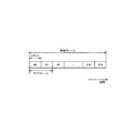
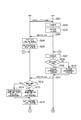
- FIG. 2 is a configuration diagram of a radio frame used in the LTE system 1.
- the LTE system 1 employs OFDMA (Orthogonal Frequency Division Multiplexing Access) for the downlink (DL) and SC-FDMA (Single Carrier Division Multiple Access) for the uplink (UL).
- OFDMA Orthogonal Frequency Division Multiplexing Access
- SC-FDMA Single Carrier Division Multiple Access
- the radio frame is composed of ten subframes arranged in the time direction, and each subframe is composed of two slots arranged in the time direction.
- the length of each subframe is 1 ms, and the length of each slot is 0.5 ms.
- Each subframe includes a plurality of resource blocks (RBs) in the frequency direction and includes a plurality of symbols in the time direction.
- the resource block is composed of 12 consecutive subcarriers, and constitutes one unit when allocating frequency / time resources to the UE.
- a guard interval called a cyclic prefix (CP) is provided at the head of each symbol.
- CP cyclic prefix
- the section of the first few symbols of each subframe is a control region mainly used as a physical downlink control channel (PDCCH).
- the remaining section of each subframe is a data area mainly used as a physical downlink shared channel (PDSCH).
- PDCCH carries a control signal.
- the control signal is, for example, uplink SI (Scheduling Information), downlink SI, and TPC bits.
- Uplink SI indicates allocation of uplink frequency / time resources
- downlink SI indicates allocation of downlink frequency / time resources.
- the TPC bit is a signal instructing increase / decrease in uplink transmission power.
- the PDSCH carries control signals and / or user data.
- the downlink data area may be allocated only to user data, or may be allocated such that user data and control signals are multiplexed.
- an acknowledgment (ACK) / negative acknowledgment (NACK) is carried via the physical HARQ notification channel (PHICH).
- ACK / NACK indicates whether or not the signal transmitted via the uplink physical channel (for example, PUSCH) has been successfully decoded.
- both ends in the frequency direction in each subframe are control regions mainly used as a physical uplink control channel (PUCCH). Further, the central portion in the frequency direction in each subframe is a data region mainly used as a physical uplink shared channel (PUSCH).
- PUCCH physical uplink control channel
- PUSCH physical uplink shared channel
- the PUCCH carries a control signal.
- the control signal includes, for example, CQI (Channel Quality Indicator), PMI (Precoding Matrix Indicator), RI (Rank Indicator), SR (Scheduling Request), ACK / NACK, and the like.
- CQI indicates a modulation scheme and a coding rate (MCS) that are preferable for use in the downlink based on the channel quality of the downlink.
- MCS coding rate
- the CQI corresponds to channel quality information.
- PMI indicates a precoder matrix (PM) preferable for use in the downlink. Specifically, the PMI indicates a precoder matrix in which the beam is directed toward the UE that is the transmission source of the PMI. In this embodiment, the PMI corresponds to precoder matrix information.
- PM precoder matrix
- RI indicates the number of layers (number of streams) preferable for use in the downlink.
- SR is a signal requesting allocation of uplink frequency / time resources (resource blocks).
- ACK / NACK indicates whether or not decoding of a signal transmitted via a downlink physical channel (for example, PDSCH) has succeeded.
- PUSCH is a physical channel that carries control signals and / or user data.
- the uplink data area may be allocated only to user data, or may be allocated such that user data and control signals are multiplexed.
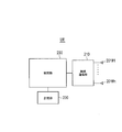
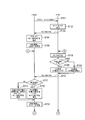
- FIG. 3 is a block diagram of the eNB.
- the eNB includes a plurality of antenna elements 101 # 0 to 101 # 3, a radio communication unit 110, a network communication unit 120, a storage unit 130, and a control unit 140.
- Antenna elements 101 # 0 to 101 # 3 are connected to antenna ports AP # 0 to AP # 3, respectively.
- the number of antenna ports AP is four, but may be two or eight.
- One antenna element 101 is connected to one antenna port AP, but two or more antenna elements 101 may be connected to one antenna port AP.
- the wireless communication unit 110 performs wireless communication via a plurality of antenna ports AP (a plurality of antenna elements 101). At the time of transmission, the radio communication unit 110 performs signal processing on the baseband signal, and then performs up-conversion and amplification, and transmits the radio signal. At the time of reception, the radio communication unit 110 performs amplification and down-conversion of the received signal, and then processes the baseband signal and outputs it to the control unit 140.
- the radio communication unit 110 transmits a cell-specific reference signal and / or a CSI reference signal (hereinafter simply referred to as “reference signal (RS)”) used for measurement and demodulation in the UE for each antenna port AP. Since the reference signal transmitted for each antenna port AP is different, the UE can perform measurement for each antenna port AP.
- RS reference signal
- the radio communication unit 110 transmits a downlink signal (control signal and / or user data) precoded using a precoder matrix via a plurality of antenna ports AP, thereby controlling directivity patterns, for example, a beam. It can be formed or a null can be formed.
- the radio communication unit 110 may support closed-loop spatial multiplexing in which a plurality of data streams (layers) are transmitted in parallel using the same frequency / time resource (resource block) based on PMI and RI fed back from the UE.
- Closed-loop spatial multiplexing includes SU-MIMO for a single user (SU) and MU-MIMO for multiple users (SU).
- FIG. 4 is a block diagram of the wireless communication unit 110 for performing spatial multiplexing. The details of each block are described in 3GPP TS 36.211. Here, the outline is described. As shown in FIG. 4, one or two codewords to be transmitted on the physical channel are scrambled and modulated into modulation symbols, and then mapped to a plurality of layers by the layer mapper 111. The code word is a data unit for error correction. The number of layers is determined based on the RI fed back from the UE.
- the precoder 112 precodes the modulation symbols of each layer using the precoder matrix for each layer.
- the precoder matrix is determined based on the PMI fed back from the UE.
- the precoded modulation symbols are mapped to resource elements, converted into time-domain OFDM signals, and output to each antenna port AP.
- the resource element is a resource unit composed of one subcarrier and one symbol.
- the network communication unit 120 communicates with the EPC using the S1 interface. Moreover, the network communication part 120 performs communication (communication between base stations) with adjacent eNB using an X2 interface.
- the storage unit 130 is configured using a memory or the like, and stores various types of information used for control by the control unit 140 and the like.
- the control unit 140 is configured using a processor or the like, and controls various functions of the eNB.
- FIG. 5 is a block diagram of the UE.
- the UE includes a plurality of antenna elements 201 # 1 to 201 # n, a wireless communication unit 210, a storage unit 220, and a control unit 230.
- the UE may include a user interface unit and a battery.
- the wireless communication unit 210 performs wireless communication via the plurality of antenna elements 201. At the time of transmission, the wireless communication unit 210 performs signal processing on the baseband signal and then performs up-conversion and amplification to transmit the wireless signal. At the time of reception, the wireless communication unit 210 performs amplification and down-conversion of the received signal, and then performs signal processing on the baseband signal and outputs it to the control unit 230.
- the radio communication unit 210 When closed-loop spatial multiplexing is performed, the radio communication unit 210 generates channel state information (CSI) based on a reference signal received from the eNB, and feeds back the channel state information to the eNB.
- the channel state information includes CQI, PMI, RI, and the like.
- Radio communication section 210 selects an appropriate precoder matrix from predetermined precoder matrix candidates (codebook) according to a predetermined standard, and feeds back the index of the selected precoder matrix as PMI.
- the radio communication unit 210 performs decoding (MIMO decoding) of a downlink signal received from the eNB based on a reference signal received from the eNB or TPMI (Transmitted PMI) notified from the eNB.
- the TPMI is information indicating a precoder matrix used by the eNB for transmission of the downlink signal, and corresponds to transmission precoder matrix information.
- the storage unit 220 is configured using a memory or the like, and stores various types of information used for control by the control unit 230 and the like.
- the control unit 230 is configured using a processor or the like, and controls various functions of the UE.
- the eNB and UE support CB (Coordinated Beamforming) -CoMP (Coordinated Multi-Point).
- CoMP positions an antenna group at the same place as one “point”, and a plurality of points cooperate to communicate with the UE.
- the point group that performs cooperative communication with the UE is referred to as a CoMP cooperating set.
- CB-CoMP is a method in which only one point holds data on the downlink and performs beam forming in cooperation with a plurality of points.
- a CoMP cooperating set is configured by a plurality of eNBs.
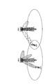
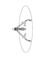
- 6 and 7 are diagrams showing the operating environment of the eNB and the UE according to the present embodiment.
- UE # 1 communicates with eNB # 1 as a serving cell
- UE # 2 communicates with eNB # 2 as a serving cell
- eNB # 1 and eNB # 2 perform CB-CoMP with UE # 1.
- eNB # 1 directs a beam toward UE # 1 under its control.
- the eNB # 2 directs a null toward the UE # 1 under the control of the eNB # 1, while directing a beam toward the UE # 2 under the control of the eNB # 2.
- UE # 1 feeds back a PMI indicating a precoder matrix whose beam is directed to UE # 1 to eNB # 1 based on a reference signal received from eNB # 1.
- UE # 1 sends a Best Companion PMI (hereinafter referred to as “BC-PMI”) indicating a precoder matrix in which a null is directed to UE # 1 to eNB # 2 based on a reference signal received from eNB # 2. Feedback.
- BC-PMI Best Companion PMI
- BC-PMI may be directly fed back from UE # 1 to eNB # 2.
- BC-PMI may be indirectly fed back from UE # 1 to eNB # 2 via eNB # 1.
- UE # 2 may feed back to the eNB # 2 a PMI indicating a precoder matrix in which the beam is directed to the UE # 2, based on the reference signal received from the eNB # 2.
- the eNB # 1 performs precoding using the precoder matrix indicated by the PMI fed back from the UE # 1, so that the beam directs the UE # 1 to the UE # 1 with a directivity pattern.
- a downlink signal is transmitted.
- eNB # 2 transmits a downlink signal to UE # 2 with a directivity pattern in which a null is directed to UE # 1 by performing precoding using the precoder matrix indicated by BC-PMI fed back from UE # 1 To do.
- precoding for directing nulls requires very high accuracy, but the values (indexes) that BC-PMI can take are limited, so eNB # 2 achieves such high accuracy Possible precoder matrices cannot be used. As a result, it is difficult to perform CB-CoMP well.
- CB-CoMP can be performed satisfactorily by the following method.
- UE # 1 selects an optimal precoder matrix from predetermined precoder matrix candidates (codebook) so that null is directed toward UE # 1, and indicates the selected precoder matrix Obtain BC-PMI.
- BC-PMI corresponds to precoder matrix information.
- UE # 1 calculates a correction value for fine-tuning the precoder matrix indicated by BC-PMI in order to improve the accuracy with which null is directed toward UE # 1, and PAI ( Get Precoding Adjustment Indicator).
- the PAI corresponds to correction value information.
- PAI is an index of the correction value calculated by UE # 1.
- BC-PMI and PAI may be fed back directly from UE # 1 to eNB # 2.
- BC-PMI and PAI may be indirectly fed back from UE # 1 to eNB # 2 via eNB # 1.
- the PAI may be fed back after the BC-PMI is fed back, not limited to the case where the PAI is fed back simultaneously as additional information of the BC-PMI.
- eNB # 2 may instruct UE # 1 to perform PAI feedback.
- the eNB # 2 reflects (multiplies) the correction value indicated by the PAI notified from the UE # 1 to the precoder matrix indicated by the BC-PMI fed back from the UE # 1, thereby the precoder matrix. Correct. Then, eNB # 2 applies the corrected precoder matrix to the transmission to UE # 2.
- UE # 1 increases the resolution of the correction value indicated by the PAI every time the PAI is fed back. For example, the resolution of the correction value indicated by the PAI is increased, such as ⁇ ⁇ / 4 for the first time and ⁇ ⁇ / 8 for the second time. However, after reaching the predetermined resolution, the increase in resolution may be stopped, that is, the resolution may reach its peak.
- the PAI may include information on the resolution of the correction value indicated by the PAI. For example, a field for storing resolution information is provided in the PAI, and if the value in the field is “0”, ⁇ ⁇ / 4 is specified, and if the value is “1”, ⁇ ⁇ / 8 is specified. it can.
- the eNB # 2 When the PAI is fed back multiple times from the UE # 1, the eNB # 2 accumulates the correction value indicated by the PAI every time the PAI is received, and the accumulated correction value (hereinafter referred to as “cumulative PAI correction value”). Called). And eNB # 2 determines the precoder matrix applied to transmission of the downlink signal to UE # 2 according to the fed back BC-PMI and the accumulated PAI correction value. Specifically, eNB # 2 corrects the precoder matrix by reflecting the accumulated PAI correction value on the precoder matrix indicated by the fed back BC-PMI.
- ENB # 2 resets the accumulated PAI when the BC-PMI to be fed back is changed. In other words, eNB # 2 continues to accumulate PAI until the BC-PMI (value) to be fed back is changed.
- null steering can be appropriately performed in CB-CoMPO.
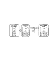
- FIG. 8 is a diagram for explaining a specific example of operations of the UE # 1 and the eNB # 2 according to the present embodiment.
- UE # 1 feeds back BC-PMI “1” to eNB # 2.
- the weight corresponding to the antenna port AP # 0 of the eNB # 2 is “1/2”
- the weight corresponding to the antenna port AP # 1 is “j / 2 ”
- the weight corresponding to the antenna port AP # 2 is“ ⁇ 1/2 ”
- the weight corresponding to the antenna port AP # 3 is“ ⁇ j / 2 ”.
- the correction value indicated by the PAI is “0” for the correction value corresponding to the antenna port AP # 0 of the eNB # 2, and “0” for the correction value corresponding to the antenna port AP # 1.
- the weight corresponding to the antenna port AP # 2 is “(1 ⁇ j) / ⁇ 2”, and the weight corresponding to the antenna port AP # 3 is “(1 + j) / ⁇ 2”.
- the precoder matrix is designed so that the weight corresponding to the antenna port AP # 0 is fixed, so that the weight corresponding to the antenna port AP # 0 is not corrected.
- ENB # 2 corrects the precoder matrix indicated by BC-PMI fed back from UE # 1 with the correction value indicated by PAI fed back from UE # 1.
- the weight corresponding to the antenna port AP # 2 is corrected from “ ⁇ 1/2” to “( ⁇ 1 + j) / 2 ⁇ 2”, and the weight corresponding to the antenna port AP # 3 is “ ⁇ ”.
- j / 2 is corrected to" (1-j) / 2 ⁇ 2 ".
- eNB # 2 determines to apply the corrected precoder matrix (PM) to downlink signal transmission to UE # 2.
- eNB # 2 transmits a downlink signal to UE # 2 using the determined precoder matrix.
- FIG. 9 is a sequence diagram showing a specific example of the operation sequence of UE # 1 and eNB # 2 according to the present embodiment.
- step S101 eNB # 2 (or eNB # 1) instructs UE # 1 to start PAI feedback in response to starting CB-CoMP.
- step S102 UE # 1 determines BC-PMI and PAI to be fed back to eNB # 2.
- step S103 UE # 1 feeds back the determined BC-PMI and PAI to eNB # 2.
- step S104 eNB # 2 determines a precoder matrix to be applied to transmission of a downlink signal to UE # 2 according to BC-PMI and PAI from UE # 1.
- step S105 eNB # 2 transmits a downlink signal to UE # 2 using the determined precoder matrix.
- step S106 UE # 1 determines BC-PMI to be fed back to eNB # 2.
- step S107 UE # 1 confirms whether the BC-PMI fed back this time is the same as the BC-PMI fed back last time.
- step S108 the UE # 1 improves the resolution of the correction value compared to the previous time, thereby improving the resolution of the current PAI. To decide.
- step S109 the UE # 1 sets the correction value to the default resolution and sets the current PAI. To decide.
- step S110 UE # 1 feeds back the determined BC-PMI and PAI to eNB # 2.
- step S111 the eNB # 2 confirms whether the BC-PMI fed back this time is the same as the BC-PMI fed back last time.
- step S112 When the BC-PMI fed back this time is the same as the BC-PMI fed back last time (step S111; YES), in step S112, the eNB # 2 has fed back the correction value indicated by the PAI fed back this time last time. Accumulate in the correction value indicated by PAI. Then, the precoder matrix indicated by the BC-PMI is corrected by the accumulated PAI correction value.
- step S111 when the BC-PMI fed back this time is different from the BC-PMI fed back last time (step S111; NO), the eNB # 2 initializes (resets) the accumulated PAI correction value in step S113. Then, the precoder matrix indicated by the BC-PMI is corrected by the correction value indicated by the PAI fed back this time.
- step S114 eNB # 2 transmits a downlink signal to UE # 2 using the corrected precoder matrix. Thereafter, the process returns to step S106.
- the LTE system 1 includes the eNB # 2 that transmits the downlink signal precoded using the precoder matrix via the plurality of antenna ports AP, and the BC that indicates a precoder matrix preferable for use in the downlink.
- -UE # 1 that feeds back PMI (precoder matrix information) to eNB # 2.
- UE # 1 feeds back PAI (correction value information) for correcting BC-PMI to eNB # 2 when feeding back BC-PMI or after feeding back BC-PMI.
- the eNB # 2 can correct the fed back BC-PMI (specifically, the precoder matrix indicated by the BC-PMI) using the fed back PAI. Null can be directed accurately.
- eNB # 2 (or eNB # 1) instructs UE # 1 to notify PAI when performing CB-CoMP.
- UE # 1 feeds back PAI in response to an instruction from eNB # 2 (or eNB # 1).
- the PAI is fed back in the case where the PAI is required, the PAI is not fed back in the case where the PAI is not required, so that an increase in overhead can be suppressed.
- UE # 1 increases the resolution of the PAI to be fed back every time the PAI is fed back.
- the PAI may include information indicating the resolution of the PAI.
- the eNB # 2 accumulates the PAI every time it receives the PAI.
- the eNB # 2 determines a precoder matrix to be applied to transmission of the downlink signal to the UE # 2, according to the BC-PMI fed back from the UE # 1 and the accumulated PAI.
- the eNB # 2 resets the accumulated PAI when the BC-PMI to be fed back is changed.
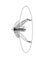
- FIG.10 and FIG.11 is a figure which shows the operation environment of eNB and UE which concern on this embodiment.
- the eNB performs closed-loop spatial multiplexing communication with two UEs (UE # 1 and UE # 2). That is, the eNB allocates the same frequency / time resource (resource block) to the UE # 1 and the UE # 2, and performs MU-MIMO.
- UE # 1 feeds back a PMI indicating a precoder matrix in which a beam is directed to UE # 1, to eNB based on a reference signal received from eNB.
- the UE # 2 feeds back the PMI indicating the precoder matrix in which the beam is directed to the UE # 2 to the eNB.
- PMI is fed back in MU-MIMO.
- BC-PMI may be fed back instead of or in addition to PMI.
- the eNB performs precoding using the precoder matrix indicated by the PMI fed back from the UE # 1, thereby the downlink to the UE # 1 with a directivity pattern in which the beam is directed to the UE # 1.
- Send a signal Moreover, eNB transmits the downlink signal to UE # 2 with the directivity pattern in which a beam is directed to UE # 2 by performing precoding using the precoder matrix which PMI fed back from UE # 2 shows.
- MU-MIMO when the UEs to be multiplexed are close to each other, it is preferable to improve the accuracy of directing the beam to each UE. Therefore, in the present embodiment, good beam forming is realized in MU-MIMO as follows.
- each UE selects an optimal precoder matrix from predetermined precoder matrix candidates (codebook) so that the beam is directed toward itself, and obtains a PMI indicating the selected precoder matrix.
- the PMI corresponds to precoder matrix information.
- each UE calculates a correction value for fine-tuning the precoder matrix indicated by the PMI in order to improve the accuracy of the beam pointing toward itself, and obtains a PAI indicating the calculated correction value.
- the PAI is used as an index of the calculated correction value.
- each UE feeds back the acquired PMI and PAI to the eNB.
- the PAI may be fed back after the feedback of the PMI, not limited to the case where the PAI is fed back simultaneously as additional information of the PMI.
- PAI feedback may not be performed.
- the eNB may instruct each UE to perform PAI feedback.
- the eNB corrects the precoder matrix by reflecting (multiplying) the correction value indicated by the PAI on the precoder matrix indicated by the fed back PMI. Then, the eNB applies the corrected precoder matrix to the transmission.
- each UE increases the resolution of the correction value indicated by the PAI every time the PAI is fed back.
- the resolution of the correction value indicated by the PAI is increased, such as ⁇ ⁇ / 4 for the first time and ⁇ ⁇ / 8 for the second time.
- the increase in resolution may be stopped, that is, the resolution may reach its peak.
- the PAI may include information on the resolution of the correction value indicated by the PAI. For example, a field for storing resolution information is provided in the PAI, and if the value in the field is “0”, ⁇ ⁇ / 4 is specified, and if the value is “1”, ⁇ ⁇ / 8 is specified. it can.
- the eNB When the PAI is fed back multiple times from each UE, the eNB accumulates the correction value indicated by the PAI every time the PAI is received for each UE, and the accumulated correction value (hereinafter referred to as “cumulative PAI correction value”). Called). Then, the eNB determines a precoder matrix to be applied to downlink signal transmission according to the fed back PMI and the accumulated PAI correction value. Specifically, the eNB corrects the precoder matrix by reflecting the accumulated PAI correction value on the precoder matrix indicated by the fed back PMI.
- ENB resets accumulated PAI when PMI fed back is changed. In other words, the eNB continues to accumulate PAI until the (feedback) PMI is changed.
- each UE when notifying PAI to the eNB, each UE corrects the CQI to be fed back to the eNB in anticipation of quality improvement by correction using the PAI.
- the eNB in the transmission mode using the cell-specific reference signal for data decoding, the eNB must notify the UE of the PMI corresponding to the precoder matrix used for transmission by the eNB as TPMI. This is because the CRS is not subjected to precoding, and therefore the UE cannot specify the precoding state (precoder matrix) based on the CRS and cannot decode the precoded data.
- the eNB corrects the precoder matrix indicated by the PMI, for the TPMI notified to the UE, if the PMI corresponding to the corrected precoder matrix is not defined, the eNB changes the PMI corresponding to the precoder matrix before the change to the TPMI. If a PMI corresponding to the corrected precoder matrix is defined, the PMI is selected as TPMI.
- DMRS DeModulation Reference Signal / UE specific Reference Signal
- FIG. 12 is a sequence diagram showing a specific example of the operation sequence of UE # 1 and eNB according to the present embodiment.
- step S201 the eNB instructs UE # 1 to start PAI feedback in response to starting MU-MIMO.
- step S202 UE # 1 determines a PMI to be fed back to the eNB.
- step S203 UE # 1 determines the PAI and CQI to be fed back to the eNB.
- UE # 1 determines the CQI that is expected to be improved by the PAI as the CQI to be fed back compared to the original CQI (that is, the CQI corresponding to the determined PMI).
- step S204 UE # 1 feeds back the determined PMI, PAI, and CQI to the eNB.
- step S205 the eNB determines a corrected precoder matrix to be applied to the transmission of the downlink signal to the UE # 1, according to the PMI and PAI fed back from the UE # 1.
- step S206 the eNB transmits a downlink signal to UE # 1 using the corrected precoder matrix and the MCS indicated by the CQI fed back from UE # 1.
- step S207 UE # 1 determines a PMI to be fed back to the eNB.
- step S208 UE # 1 confirms whether the PMI fed back this time is the same as the PMI fed back last time.
- step S209 the UE # 1 determines the current PAI so as to improve the resolution of the correction value compared to the previous time. In this case, UE # 1 determines the CQI that is expected to be improved by the cumulative correction as the CQI to be fed back in consideration of the cumulative correction by PAI.
- step S210 UE # 1 determines the current PAI so that the correction value becomes the default resolution. In this case, UE # 1 determines the CQI that is expected to be improved by PAI as compared to the original CQI (that is, the CQI corresponding to the determined PMI) as the CQI to be fed back.
- step S211 UE # 1 feeds back the determined PMI, PAI, and CQI to the eNB.
- step S212 the eNB confirms whether the PMI fed back this time is the same as the PMI fed back last time.
- step S213 the eNB changes the correction value indicated by the PAI fed back this time to the correction value indicated by the PAI fed back last time. Accumulate. Then, the precoder matrix indicated by the PMI is corrected by the accumulated PAI correction value.
- step S212 when the PMI fed back this time is different from the PMI fed back last time (step S212; NO), the eNB initializes (resets) the accumulated PAI correction value in step S214. Then, the precoder matrix indicated by the PMI is corrected by the correction value indicated by the PAI fed back this time.
- step S215 the eNB transmits a downlink signal to the UE # 1 using the corrected precoder matrix and the MCS indicated by the CQI fed back from the UE # 1.
- UE # 1 feeds back PAI (correction value information) for correcting PMI to eNB when feeding back PMI or after feeding back PMI.
- PAI correction value information
- the eNB can correct the fed back PMI (specifically, the precoder matrix indicated by the PMI) using the fed back PAI, and thus directs the beam to UE # 1 with high accuracy. Can do.
- the eNB instructs UE # 1 to notify PAI when performing MU-MIMO.
- UE # 1 feeds back PAI in response to an instruction from the eNB.
- the PAI is fed back in the case where the PAI is required, the PAI is not fed back in the case where the PAI is not required, so that an increase in overhead can be suppressed.
- UE # 1 increases the resolution of the PAI to be fed back every time the PAI is fed back.
- the PAI may include information indicating the resolution of the PAI.
- the eNB accumulates the PAI every time it receives the PAI.
- the eNB determines a precoder matrix to be applied to transmission of the downlink signal to the UE # 1, according to the PMI fed back from the UE # 1 and the accumulated PAI.
- the eNB resets the accumulated PAI when the fed back PMI is changed.
- the first embodiment and the second embodiment described above are not limited to being implemented separately and can be implemented in combination with each other. That is, the present invention can be applied to an operating environment in which CB-CoMP and MU-MIMO are used in combination.
- the present invention is useful in the mobile communication field.
Landscapes
- Engineering & Computer Science (AREA)
- Computer Networks & Wireless Communication (AREA)
- Signal Processing (AREA)
- Quality & Reliability (AREA)
- Physics & Mathematics (AREA)
- Mathematical Physics (AREA)
- Mobile Radio Communication Systems (AREA)
- Radio Transmission System (AREA)
Abstract
Priority Applications (3)
| Application Number | Priority Date | Filing Date | Title |
|---|---|---|---|
| US14/381,097 US9531453B2 (en) | 2012-02-29 | 2013-02-27 | Communication control method, user terminal, and base station |
| EP13754735.2A EP2822314A4 (fr) | 2012-02-29 | 2013-02-27 | Procédé de commande de communication, terminal utilisateur et station de base |
| JP2014502325A JP5841232B2 (ja) | 2012-02-29 | 2013-02-27 | 通信制御方法、ユーザ端末、基地局、及びプロセッサ |
Applications Claiming Priority (2)
| Application Number | Priority Date | Filing Date | Title |
|---|---|---|---|
| US201261604685P | 2012-02-29 | 2012-02-29 | |
| US61/604,685 | 2012-02-29 |
Publications (1)
| Publication Number | Publication Date |
|---|---|
| WO2013129504A1 true WO2013129504A1 (fr) | 2013-09-06 |
Family
ID=49082698
Family Applications (1)
| Application Number | Title | Priority Date | Filing Date |
|---|---|---|---|
| PCT/JP2013/055200 WO2013129504A1 (fr) | 2012-02-29 | 2013-02-27 | Procédé de commande de communication, terminal utilisateur et station de base |
Country Status (4)
| Country | Link |
|---|---|
| US (1) | US9531453B2 (fr) |
| EP (1) | EP2822314A4 (fr) |
| JP (1) | JP5841232B2 (fr) |
| WO (1) | WO2013129504A1 (fr) |
Cited By (1)
| Publication number | Priority date | Publication date | Assignee | Title |
|---|---|---|---|---|
| WO2015064524A1 (fr) * | 2013-10-29 | 2015-05-07 | 京セラ株式会社 | Procédé de commande de communication et station de base |
Families Citing this family (7)
| Publication number | Priority date | Publication date | Assignee | Title |
|---|---|---|---|---|
| JP2013236122A (ja) * | 2012-05-02 | 2013-11-21 | Fujitsu Ltd | 基地局装置及び送信電力制御方法 |
| KR102143791B1 (ko) * | 2012-10-19 | 2020-08-12 | 삼성전자주식회사 | 다중 사용자 무선 시스템과 하이브리드 자동 재전송에서의 채널 출력 피드백 적용 |
| US9825666B2 (en) * | 2014-01-28 | 2017-11-21 | Maxlinear Asia Singapore Private Limited | Communication system for telephone line access with crosstalk stability |
| WO2015114442A1 (fr) | 2014-01-28 | 2015-08-06 | Marvell World Trade Ltd. | Système de communication pour l'accès à une ligne téléphonique présentant une stabilité diaphonique |
| US10205494B2 (en) * | 2014-07-31 | 2019-02-12 | Lg Electronics Inc. | Method for supporting D2D communication to which MIMO technology is applied and device therefor |
| CN105450343B (zh) * | 2014-08-30 | 2018-11-06 | 华为技术有限公司 | 一种预编码的方法、装置及系统 |
| WO2016190215A1 (fr) * | 2015-05-22 | 2016-12-01 | 株式会社Nttドコモ | Terminal d'utilisateur, station de base sans fil, et procédé de communication sans fil |
Citations (3)
| Publication number | Priority date | Publication date | Assignee | Title |
|---|---|---|---|---|
| WO2010109518A1 (fr) * | 2009-03-24 | 2010-09-30 | 富士通株式会社 | Système de communication sans fil, dispositif de terminal, dispositif de station de base, procédé de communication sans fil dans un système de communication sans fil |
| US20110007685A1 (en) * | 2009-07-10 | 2011-01-13 | Futurewei Technologies, Inc. | System and Method for Downlink Channel Sounding in Wireless Communications Systems |
| US20110170623A1 (en) * | 2010-01-12 | 2011-07-14 | Pantech Co., Ltd. | Apparatus and method for channel information feedback, base station receiving the channel information, and communication method of the base station |
Family Cites Families (13)
| Publication number | Priority date | Publication date | Assignee | Title |
|---|---|---|---|---|
| US8179775B2 (en) | 2007-08-14 | 2012-05-15 | Texas Instruments Incorporated | Precoding matrix feedback processes, circuits and systems |
| CN101388699A (zh) * | 2007-09-12 | 2009-03-18 | 夏普株式会社 | 基于空时频域的信息反馈方法和系统、用户设备及基站 |
| US8649456B2 (en) * | 2009-03-12 | 2014-02-11 | Futurewei Technologies, Inc. | System and method for channel information feedback in a wireless communications system |
| JP2011004161A (ja) * | 2009-06-18 | 2011-01-06 | Sharp Corp | 通信システム、通信装置および通信方法 |
| EP2478646B1 (fr) * | 2009-09-16 | 2017-08-16 | LG Electronics Inc. | Appareil et procédé de transmission d'informations de commande de liaison montante |
| CN102640431A (zh) * | 2009-10-30 | 2012-08-15 | 诺基亚公司 | 支持有效的秩重配的信道反馈 |
| WO2011085082A2 (fr) * | 2010-01-08 | 2011-07-14 | Interdigital Patent Holdings, Inc. | Retour d'informations sans fil amélioré |
| WO2011096646A2 (fr) * | 2010-02-07 | 2011-08-11 | Lg Electronics Inc. | Procédé et appareil pour émettre un signal de référence descendant dans un système de communication sans fil prenant en charge plusieurs antennes |
| KR101231487B1 (ko) | 2010-06-03 | 2013-02-07 | (주)휴맥스 | 차분 선부호화 방법 및 그 방법을 지원하는 기지국 |
| HUE046967T2 (hu) * | 2010-10-04 | 2020-04-28 | Samsung Electronics Co Ltd | Eljárás és berendezés kódkönyv alhalmazkorlátozás bitmap átvitelére és vételére |
| US8611449B2 (en) * | 2010-11-15 | 2013-12-17 | FutureWei Technologes, Inc. | Method and apparatus for demodulation of a reference signal |
| KR102585652B1 (ko) * | 2011-01-07 | 2023-10-05 | 인터디지탈 패튼 홀딩스, 인크 | 다중 송신 포인트의 채널 상태 정보(csi) 전달 |
| US9294179B2 (en) * | 2012-02-07 | 2016-03-22 | Google Technology Holdings LLC | Gain normalization correction of PMI and COI feedback for base station with antenna array |
-
2013
- 2013-02-27 JP JP2014502325A patent/JP5841232B2/ja not_active Expired - Fee Related
- 2013-02-27 EP EP13754735.2A patent/EP2822314A4/fr not_active Withdrawn
- 2013-02-27 WO PCT/JP2013/055200 patent/WO2013129504A1/fr active Application Filing
- 2013-02-27 US US14/381,097 patent/US9531453B2/en active Active
Patent Citations (3)
| Publication number | Priority date | Publication date | Assignee | Title |
|---|---|---|---|---|
| WO2010109518A1 (fr) * | 2009-03-24 | 2010-09-30 | 富士通株式会社 | Système de communication sans fil, dispositif de terminal, dispositif de station de base, procédé de communication sans fil dans un système de communication sans fil |
| US20110007685A1 (en) * | 2009-07-10 | 2011-01-13 | Futurewei Technologies, Inc. | System and Method for Downlink Channel Sounding in Wireless Communications Systems |
| US20110170623A1 (en) * | 2010-01-12 | 2011-07-14 | Pantech Co., Ltd. | Apparatus and method for channel information feedback, base station receiving the channel information, and communication method of the base station |
Non-Patent Citations (2)
| Title |
|---|
| "TS 36.300 V11. 0. 0", 3GPP TECHNOLOGY SPECIFICATIONS, December 2011 (2011-12-01) |
| See also references of EP2822314A4 |
Cited By (1)
| Publication number | Priority date | Publication date | Assignee | Title |
|---|---|---|---|---|
| WO2015064524A1 (fr) * | 2013-10-29 | 2015-05-07 | 京セラ株式会社 | Procédé de commande de communication et station de base |
Also Published As
| Publication number | Publication date |
|---|---|
| JPWO2013129504A1 (ja) | 2015-07-30 |
| EP2822314A4 (fr) | 2015-10-28 |
| EP2822314A1 (fr) | 2015-01-07 |
| US9531453B2 (en) | 2016-12-27 |
| US20150049688A1 (en) | 2015-02-19 |
| JP5841232B2 (ja) | 2016-01-13 |
Similar Documents
| Publication | Publication Date | Title |
|---|---|---|
| JP5841232B2 (ja) | 通信制御方法、ユーザ端末、基地局、及びプロセッサ | |
| JP6148718B2 (ja) | 通信制御方法、ユーザ端末、及び基地局 | |
| EP3375238B1 (fr) | Système et procédé pour la transmission et la réception de canaux de commande et de données avec un signal de référence de groupe | |
| US9184818B2 (en) | Method and apparatus for transreceiving channel state information in cooperative multipoint communication system | |
| JP5993238B2 (ja) | 通信システム、基地局装置、端末装置、及び通信方法 | |
| KR101769382B1 (ko) | 무선 통신 시스템에서 채널 상태 정보를 보고하는 방법 및 이를 위한 장치 | |
| WO2014038321A1 (fr) | Procédé de communication radio, terminal d'utilisateur, station de base radio, et système de communication radio | |
| WO2014042479A1 (fr) | Procédé et appareil de réception de données dans un système de communication sans fil supportant une transmission coopérative | |
| EP2981038A1 (fr) | Dispositif de communication radio et procédé de traitement de signal | |
| US20120170679A1 (en) | Method for transceiving reference signal in comp operation in wireless communication system that supports an mu-mimo scheme | |
| US10015816B2 (en) | Network apparatus and user terminal | |
| US20130242896A1 (en) | Method and apparatus for receiving a signal in a wireless communication system that supports mu-mimo scheme | |
| US9698886B2 (en) | Base station, communication control method, and processor | |
| WO2019140389A1 (fr) | Équipement utilisateur et procédé de communication sans fil | |
| WO2014109613A1 (fr) | Procédé et appareil pour transmettre/recevoir des informations d'état de canal dans un système de communications sans fil | |
| US9893778B2 (en) | Method and apparatus for transreceiving channel state information in wireless communication system | |
| EP3613248A1 (fr) | Système et procédé d'indication d'autorisations de programmation | |
| KR20190068611A (ko) | 다운링크 제어 채널들과 비주기적인 채널 상태 정보-기준 신호들 사이의 충돌 회피 | |
| US9537550B2 (en) | Mobile communication system, user terminal, and processor | |
| US20170195011A1 (en) | Communication control method, base station, and processor |
Legal Events
| Date | Code | Title | Description |
|---|---|---|---|
| 121 | Ep: the epo has been informed by wipo that ep was designated in this application |
Ref document number: 13754735 Country of ref document: EP Kind code of ref document: A1 |
|
| ENP | Entry into the national phase |
Ref document number: 2014502325 Country of ref document: JP Kind code of ref document: A |
|
| WWE | Wipo information: entry into national phase |
Ref document number: 14381097 Country of ref document: US |
|
| WWE | Wipo information: entry into national phase |
Ref document number: 2013754735 Country of ref document: EP |
|
| NENP | Non-entry into the national phase |
Ref country code: DE |