WO2013129151A1 - プラズマ-mig溶接方法および溶接トーチ - Google Patents
プラズマ-mig溶接方法および溶接トーチ Download PDFInfo
- Publication number
- WO2013129151A1 WO2013129151A1 PCT/JP2013/053815 JP2013053815W WO2013129151A1 WO 2013129151 A1 WO2013129151 A1 WO 2013129151A1 JP 2013053815 W JP2013053815 W JP 2013053815W WO 2013129151 A1 WO2013129151 A1 WO 2013129151A1
- Authority
- WO
- WIPO (PCT)
- Prior art keywords
- plasma
- mig
- welding
- torch
- wire
- Prior art date
- Legal status (The legal status is an assumption and is not a legal conclusion. Google has not performed a legal analysis and makes no representation as to the accuracy of the status listed.)
- Ceased
Links
Images


Classifications
-
- B—PERFORMING OPERATIONS; TRANSPORTING
- B23—MACHINE TOOLS; METAL-WORKING NOT OTHERWISE PROVIDED FOR
- B23K—SOLDERING OR UNSOLDERING; WELDING; CLADDING OR PLATING BY SOLDERING OR WELDING; CUTTING BY APPLYING HEAT LOCALLY, e.g. FLAME CUTTING; WORKING BY LASER BEAM
- B23K9/00—Arc welding or cutting
- B23K9/16—Arc welding or cutting making use of shielding gas
- B23K9/173—Arc welding or cutting making use of shielding gas and of a consumable electrode
-
- B—PERFORMING OPERATIONS; TRANSPORTING
- B23—MACHINE TOOLS; METAL-WORKING NOT OTHERWISE PROVIDED FOR
- B23K—SOLDERING OR UNSOLDERING; WELDING; CLADDING OR PLATING BY SOLDERING OR WELDING; CUTTING BY APPLYING HEAT LOCALLY, e.g. FLAME CUTTING; WORKING BY LASER BEAM
- B23K10/00—Welding or cutting by means of a plasma
- B23K10/02—Plasma welding
-
- B—PERFORMING OPERATIONS; TRANSPORTING
- B23—MACHINE TOOLS; METAL-WORKING NOT OTHERWISE PROVIDED FOR
- B23K—SOLDERING OR UNSOLDERING; WELDING; CLADDING OR PLATING BY SOLDERING OR WELDING; CUTTING BY APPLYING HEAT LOCALLY, e.g. FLAME CUTTING; WORKING BY LASER BEAM
- B23K9/00—Arc welding or cutting
- B23K9/24—Features related to electrodes
- B23K9/28—Supporting devices for electrodes
- B23K9/29—Supporting devices adapted for making use of shielding means
- B23K9/291—Supporting devices adapted for making use of shielding means the shielding means being a gas
- B23K9/295—Supporting devices adapted for making use of shielding means the shielding means being a gas using consumable wire electrodes
-
- H—ELECTRICITY
- H05—ELECTRIC TECHNIQUES NOT OTHERWISE PROVIDED FOR
- H05H—PLASMA TECHNIQUE; PRODUCTION OF ACCELERATED ELECTRICALLY-CHARGED PARTICLES OR OF NEUTRONS; PRODUCTION OR ACCELERATION OF NEUTRAL MOLECULAR OR ATOMIC BEAMS
- H05H1/00—Generating plasma; Handling plasma
- H05H1/24—Generating plasma
- H05H1/26—Plasma torches
- H05H1/32—Plasma torches using an arc
- H05H1/34—Details, e.g. electrodes, nozzles
Definitions
- the present invention relates to a technique for assisting consumable electrode welding by plasma, and more particularly, to a plasma-MIG welding method and a welding torch.
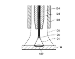
- the conventional typical MIG torch includes an MIG chip 101, a welding wire 102 inserted into the chip, and a shield nozzle 103. Then, for example, via a MIG tip 101 for feeding the MIG welding power supply (not shown) which is a DC power supply, to supply power to generate arc (MIG arc) 104 to the welding wire 102 as a consumable electrode. At this time, a shield gas 105 such as argon is supplied between the MIG chip 101 and the shield nozzle 103. As shown in FIG.
- the central axis of the MIG chip 101 and the shield nozzle 103 coincide (coaxial), and the tip side faces the surface of the workpiece W. That, MIG chip 101 faces the lower tip side, the welding wire 102 as a welding material melts, falling on the surface of the workpiece W beneath droplet 106 is approximately the tip, the molten pool 107 on the surface of the workpiece W is Generated.
- a plasma-MIG welding method is known (see, for example, Patent Document 1).
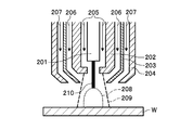
- a conventional typical plasma-MIG torch includes an MIG chip 201 for supplying power to a welding wire 210 as a consumable electrode, a plasma electrode 202, a plasma nozzle 203, a shield nozzle 204, Is provided.
- the plasma electrode 202 which is a hollow electrode is formed of a water-cooled conductive member, and is disposed outside the MIG chip 201.
- the plasma nozzle 203 is disposed outside the plasma electrode 202, and the shield nozzle 204 is disposed outside the plasma nozzle 203.
- the MIG tip 201 and the welding wire 210, the plasma electrode 202, the plasma nozzle 203, and the shield nozzle 204 have the same center axis (coaxial), and the tip side faces the surface of the workpiece W. Yes. That is, the tip end of the MIG chip 201, the plasma electrode 202, the plasma nozzle 203, and the shield nozzle 204 faces downward, and the welding wire 210 that is the welding material melts on the surface of the workpiece W just below the molten metal when melted. Fall.
- Droplet transfer models are distinguished according to the magnitude of the welding current, for example, spray transfer in a large current region of about 300 A or more, short circuit transfer in a small current region of about 150 A or less, and intermediate current region in the middle. The globule transition is known.
- the difference in the magnitude of the welding current is associated with, for example, a difference in workpiece material and a thickness that are assumed to be welded.
- the workpiece material is the same and the thickness is different.
- workpieces used for ships, nuclear power, bridges, buildings, etc. are assumed to have a thickness of about 20 to 30 mm, for example. These are called thick plate region workpieces.
- a workpiece having a thickness of about 2 mm or a stack of about 4 mm is assumed as a work used for a vehicle body such as an automobile. These are called thin plate region workpieces.
- an object of the present invention is to provide a plasma-MIG welding method and a welding torch that can solve the above-described problems and can reduce the spatter amount without depending on the control of the MIG welding power source.
- a plasma-MIG welding method includes a plasma torch portion including a plasma nozzle and a plasma electrode, and an MIG torch including an MIG tip and a welding wire in a different direction and a predetermined distance.
- a welding method using a plasma-MIG welding apparatus arranged at a distance from each other, wherein a plasma arc is locally overlapped with the tip of the welding wire and heated to promote melting of the welding wire In this state, MIG welding is performed without causing a short circuit between the tip of the welding wire, which is a consumable electrode, and the workpiece.
- the melting of the welding wire for inserting the MIG tip is accelerated by the plasma in the MIG torch droplet of the welding wire is produced by melting is aerial spraying, there is no thing occur short circuit. For this reason, even if a low MIG welding current is actually supplied so that the droplet transfer model is a short-circuit transfer, the tip of the welding wire is large so that the droplet transfer model is a drop transfer. The effect is as if the MIG welding current was supplied. Therefore, the amount of spatter can be reduced without depending on the control of the MIG welding power source.
- the plasma -MIG welding method according to the present invention it is preferred to heat the part at a tip end portion of the tip protruding portion where the welding wire protruding from the nozzle shield gas supplied to the MIG torch .
- the protruding portion from which the welding wire protrudes is not heated as a whole, so the size of the droplet generated by melting the welding wire can be changed to the desired size by appropriately changing the heating portion. Can be. Therefore, the transition of the droplets can be stabilized by managing the length of the heated portion of the protruding portion of the welding wire.
- the tip portion of the protruding portion of the welding wire that is 3 to 10 times the diameter of the welding wire.
- the welding wire it is preferable to heat the welding wire so as to generate a droplet having a diameter of 1 to 2 times the diameter of the welding wire by promoting the melting of the welding wire.
- the size of the droplet is reduced from about 1/3 to 1/2 compared to the case of the globule transfer, so the transfer of the droplet is stabilized and the amount of spatter can be effectively reduced.
- the amount of spatter can be reduced without depending on the control of the MIG welding power source.
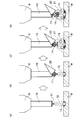
- FIG. 4A and 4B are schematic views of a wire tip when the plasma-MIG welding method according to the present invention is used, where FIG. 5A is a state of the wire tip at the start of MIG welding, and FIG. 5B is a wire tip at the start of heating by plasma.
- C shows the state of the wire tip after stabilization of the plasma arc, and
- d shows the state where the molten metal is separated from the wire tip.
- It is a schematic diagram of a welding torch, (a) is a plasma torch part and MIG torch housed in the welding torch, (b) is an arrangement for specifying the relative position of the plasma torch part and the nozzle direction with respect to the MIG torch. An example of parameter design is shown.
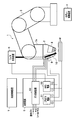
- FIG. 1 is a schematic diagram showing a configuration of a welding system for performing a plasma-MIG welding method according to the present invention.
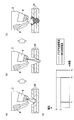
- An explanatory view of a procedure of the penetration welding process according to the comparative example (a) shows the digging step, (b) the extinguishing of digging completion and plasma arc, (c) is filling step, (d) a through The time change of the MIG welding current and plasma welding current at the time of welding is shown.
- a diagram of a procedure when the plasma -MIG welding method according to the present invention is applied to penetration welding (a) shows the digging step, (b) is filling step, (c) the MIG welding during penetration welding The time change of electric current and plasma welding current is shown.
- a positive electrode of a MIG welding power source (not shown) is connected to the MIG torch 9 shown in FIG. 1A, and a negative electrode of the power source is connected to a workpiece W as a base material.
- a welding wire hereinafter simply referred to as a wire 10
- a MIG arc 12 is generated between the workpiece W and the workpiece W.
- Electrons carry charges 13 between the electrodes (wires 10). Generally, sputtering occurs when a charged wire contacts (short-circuits) a molten pool.
- the welding torch 2 shown in FIG. 2 (a) combines the function of housing the plasma torch unit 8 and the MIG torch 9 and the function of a shield nozzle for the shield gas supplied to the MIG torch 9. .
- the plasma torch part 8 and the MIG torch 9 are separated from each other by a predetermined distance in different directions, and the central axis of the plasma torch part 8 and the central axis of the MIG torch 9 are acute angles (for example, At 15 °).
- the plasma torch unit 8 is directed downward to the left in FIG. 2A, and the direction of the MIG torch 9 and the direction of delivery of the inserted wire 10 are directed downward to the right in FIG.
- the relative distance of the plasma torch part 8 with respect to the MIG torch 9 in the direction of the axis L 1 is R 2
- the relative distance of the plasma torch part 8 with respect to the MIG torch 9 in the direction perpendicular to the axis L 1 is R 1. It is.
- direction X direction of the axis L 1 if the direction perpendicular to the axis L 1 and the Y direction, the shift amount in the X and Y directions (R 1, R 2), a plasma torch for MIG torch 9
- the relative position of the part 8 can be determined. If the plasma torch part 8 is arranged with respect to the MIG torch 9 so that the plasma 20 from the plasma torch part 8 can move so as not to heat the tip of the wire 10 and short-circuit the droplet, these parameters can be obtained.
- the value is not particularly limited.
- the diameter of the droplet that generates melting of a powered wire 10 by promoting the plasma heats is 1 to 2 times the wire diameter It is preferable because the amount of sputtering is reduced.
- the droplet size may be in the range of 1 to 2 mm. In the case of globule transfer, when the wire diameter is 1 mm, the size of the droplet becomes 3 to 4 mm or more, and the amount of spatter increases.
- the robot controller 4 and the welding control device 7 for example, CPU (Central Processing Unit), ROM (Read Only Memory), RAM (Random Access Memory), HDD (Hard Disk Drive), provided with input and output interface and the like Yes.
- CPU Central Processing Unit
- ROM Read Only Memory
- RAM Random Access Memory
- HDD Hard Disk Drive
- the welding torch 2 includes a plasma torch portion 8 and an MIG torch 9.
- Plasma torch 8 is a torch used to assist the MIG welding by filling step P2. Moreover, the plasma torch part 8 is used in order to form the through-hole which penetrates the some workpiece
- the plasma torch unit 8 is provided with a plasma electrode and a plasma nozzle for performing plasma arc welding, and is supplied with an operating gas such as argon and a shielding gas.
- the plasma torch unit 8 generates a pilot arc between a tungsten electrode as a plasma electrode and a water-cooled constraining nozzle (plasma nozzle), converts the working gas into plasma by the heat of the pilot arc, and ejects the workpiece W.
- a plasma arc is generated between the two.
- the shielding gas such as commonly used MAG gas (Ar + CO 2 mixed gas) is supplied.
- the MIG power supply 52 supplies power to the MIG torch 9 in the hole filling process P2 (during MIG welding).
- the anode of the MIG power source 52 is electrically connected to the wire 10 (consumable electrode) via the MIG chip of the MIG torch 9, and the negative electrode of the MIG power source 52 is electrically connected to the workpiece W.
- the output characteristic of the MIG power supply 52 is a constant voltage characteristic, whereby the arc length after arc stabilization is maintained at a constant value.
- the gas supply device 53 supplies a welding shield gas to the welding torch 2 from a gas cylinder (not shown). Further, the gas supply device 53 supplies a working gas for forming plasma to the welding torch 2 from a gas cylinder (not shown). The gas supply device 53 adjusts the flow rate of the working gas and the shield gas flowing at a predetermined pressure by a command signal from the welding control device 7 using an on-off valve (not shown). In order to prevent the plasma arc from becoming unstable, in the hole filling step P2 (during MIG welding), the amount of plasma gas is preferably set to 3 L / min or less, for example.
- the wire supply device 6 is connected to the MIG power source 52. In the hole filling process P2 (during MIG welding), the wire supply device 6 sends a wire sent from a wire container (not shown) through a delivery path to the MIG torch 9.
- the welding control device 7 drives the welding power source 5 in the hole filling step P2, thereby filling the through holes with MIG welding. That is, the welding control device 7 drives the MIG power source 52, the gas supply device 53, and the MIG torch 9. At this time, the welding control device 7 continues to drive the plasma power source 51 and the plasma torch unit 8 used for drilling in the drilling process P1. As a result, the welding control device 7 irradiates the tip of the wire 10 delivered from the MIG torch 9 with the plasma arc from the plasma torch portion 8 to promote melting of the tip of the wire 10.
- Comparative example of through welding method> As shown in FIG. 4A, the welding system of the comparative example digs a hole in the workpiece W by plasma arc welding with the plasma torch portion 8 in the welding torch 2 as shown in FIG. Then, as shown in FIG. 4B, when the through hole of a desired size is formed and the digging is completed, the plasma arc is extinguished. Then, as shown in FIG. 4C, hole filling is performed by MIG welding. An example of the time change of the MIG welding current and the plasma welding current at this time is shown in FIG.
- the horizontal axis indicates time, and the vertical axis indicates welding current.
- the solid line indicates the plasma welding current
- the broken line indicates the MIG welding current.
- the welding system of the comparative example starts the digging process P1 at time t 1 with a predetermined current value I 1 (for example, 100 A) of the plasma welding current.
- I 1 for example, 100 A
- Welding system of the comparative example when completing the digging process P1 to time t 2, the extinguishing plasma arc and the plasma welding current to 0A.
- the hole filling process P 2 is started at a predetermined current value I 2 (for example, 150 A) of the MIG welding current.
- I 2 for example, 150 A
- the welding system 1 digs a hole in the workpiece W by plasma arc welding with a plasma torch part 8 in the welding torch 2 as shown in FIG. Then, when the through-hole of a desired size is formed and the digging is completed, the hole is filled as shown in FIG. 5B without extinguishing the plasma arc. At that time, as shown in FIGS. 1B, 1C, and 1D, the tip 11 of the wire 10 is selectively heated and melted by the plasma 20. An example of the time change of the MIG welding current and the plasma welding current at this time is shown in FIG.
- the horizontal axis, vertical axis, solid line, and broken line of the graph in FIG. 5C are the same as those in FIG. 4D, respectively.
- the predetermined current value I 1 in FIG. 5C is different from the predetermined current value I 1 in FIG. 4D, and the times t 4 , t 5 , and t 6 in FIG. Is different from the times t 1 , t 2 , and t 3 .
- the welding system 1 starts the digging process P1 at time t 4 with a predetermined current value I 1 (for example, 100 A) of the plasma welding current. Welding system 1 is also completed digging process P1 at time t 5, keep maintain the plasma welding current to a predetermined current value I 1. Further, at time t 5 , the hole filling process P2 is started at a predetermined current value I 1 (for example, 100 A) of the MIG welding current. The welding system 1 completes the filling process P2 at time t 6, respectively extinguishing the plasma arc and MIG arc to the plasma welding current and MIG welding current 0A.
- I 1 for example, 100 A
- the predetermined current value I 1 If is the same as the predetermined current value I 1 (e.g., 100A) shown in FIG. 4 (d) in FIG. 5 (c), the period from time t 4 ⁇ t 5 shown in FIG. 5 (c) (For example, 2 seconds) and a period between times t 5 and t 6 (for example, 0.6 seconds), a period between times t 1 and t 2 (for example, 2 seconds) and times t 2 to t 3 in FIG. The period (for example, 0.6 seconds) coincides with each other.
- plasma assistance is added to the MIG welding in the hole filling process P2, so that the MIG welding current can be reduced as compared with the comparative example, and the spatter reduction effect is achieved.
- the plasma-MIG welding method of the present invention is not limited to the above-described embodiments.
- the plasma MIG method is applied to the penetration welding method, it is not essential that the workpiece has a hole. That is, the plasma -MIG welding method of the present invention is not limited to the application to the penetration welding, even if we have a simple, reducing the sputtering by assisting in plasma when the MIG welding Can do.
- the MIG welding power source may be a DC power source or a pulse power source. Further, the plasma-MIG welding method of the present invention may be applied to MAG welding.
- MIG welding current (also simply referred to as MIG current) was a constant value (150A).
- the diameter of the wire was 1 mm.
- plasma current indicates plasma welding current.
- protruding length T represents the length T shown in FIG.
- MIG arc state is unstable corresponds to an excessive arc length.
- the droplet size indicates an average value of the sizes of a plurality of droplets observed with a high-speed camera.
- MIG sputtering indicates a value obtained by calculating an average value of the amount of sputtering generated at one hit point when sputtering occurs. This was calculated by collecting the spatter scattered and determining the total weight and dividing by the total number of welding points.
- Example 1 ⁇ Experiment 1>
- the MIG welding current was set to 150 A
- the plasma welding current was changed to 0, 100, 125, 150, 175, and 200 A
- the sputtering amount was measured without changing other conditions.
- Samples No. 1 to No. 6 at this time are referred to as Comparative Example 1, Comparative Example 2, Example 1, Example 2, Example 3, and Comparative Example 3 in this order.
- Comparative Example 1 since there is no heating of the wire by the plasma, transition mode of a droplet from the wire, a short circuit transfer mode. Therefore, spatter occurred before and after the short circuit.
- Comparative Example 2 since the wire is not heated by plasma and the wire is not sufficiently melted, the transfer mode of the droplet from the wire is the short-circuit transfer mode. Therefore, spatter occurred before and after the short circuit.
Landscapes
- Engineering & Computer Science (AREA)
- Physics & Mathematics (AREA)
- Plasma & Fusion (AREA)
- Mechanical Engineering (AREA)
- Spectroscopy & Molecular Physics (AREA)
- Arc Welding In General (AREA)
Description
このようにすることで、溶接ワイヤが溶融して発生する溶滴のサイズが小さくなるので、溶滴の移行が安定する。したがって、スパッタ量を効果的に低減できる。
ここでは、本発明の実施形態に係るプラズマ-MIG溶接方法の概要について図1(a),(b),(c),(d)を参照して説明する。
図1(a)に示すMIGトーチ9には、図示しないMIG用溶接電源の正極が接続されると共に、電源の負極が母材であるワークWに接続されている。MIG溶接を開始すると、MIGトーチ9から送出される溶接ワイヤ(以下、単にワイヤ10と表記する)は、給電により先端11が発熱し、ワークWとの間にMIGアーク12が発生し、ワークWと電極(ワイヤ10)間では電子が電荷13を運ぶ。一般に、電荷を持ったワイヤが溶融池に接触(短絡)する時にスパッタが発生する。
ここでは、本発明に係るプラズマ-MIG溶接方法を実施するための溶接システムの構成について図3を参照して説明する。溶接システム1は、重ね合わせた複数のワークWを貫通溶接するためのロボットアーク溶接システムである。貫通溶接方法は、貫通孔を形成するための段階(以下、穴掘り工程P1と称する)と、穴掘り工程P1の後であって貫通孔にワイヤを充填する段階(以下、穴埋め工程P2と称する)とを有する。本発明に係るプラズマ-MIG溶接方法を、穴埋め工程P2にて、実施することとする。
プラズマトーチ部8は、穴埋め工程P2にてMIG溶接をアシストするために用いられるトーチである。また、プラズマトーチ部8は、穴掘り工程P1にて複数のワークWを貫通する貫通孔を形成するために用いられる。プラズマトーチ部8には、プラズマアーク溶接を行うためのプラズマ電極やプラズマノズルが形成されており、アルゴン等の動作ガス及びシールドガスが供給される。プラズマトーチ部8は、プラズマ電極としてのタングステン電極と、水冷された拘束ノズル(プラズマノズル)との間にパイロットアークを発生させ、このパイロットアークの熱により動作ガスをプラズマ化して噴出させ、ワークWとの間にプラズマアークを発生させる。シールドガスとしては、一般的に用いられるMAGガス(Ar+CO2混合ガス)などが供給される。
ロボット制御装置4は、ロボット3に接続されており、溶接経路等の入力コマンドまたは予め記憶されたコマンドに基づいてロボット3の動作や姿勢を制御するものである。
溶接制御装置7は、穴掘り工程P1にて溶接電源5を駆動することで、プラズマアーク溶接により、重ね合わされた複数のワークWを貫通する貫通孔を形成する。すなわち、溶接制御装置7は、プラズマ電源51、ガス供給装置53およびプラズマトーチ部8を駆動する。
ここでは、本発明のプラズマMIG方法と比較するために、溶接システム1の前記した穴掘り工程P1における処理と穴埋め工程P2の処理とは異なる手順で貫通溶接を行う溶接システムを比較例として想定する。この比較例の溶接システムにおける貫通溶接方法の手順について図4(a),(b),(c),(d)を参照して説明する。なお、図3に示した溶接システム1と同様の構成には同じ符号を付して説明を適宜省略する。
比較例の溶接システムは、穴掘り工程P1において、図4(a)に示すように、溶接トーチ2内のプラズマトーチ部8によって、プラズマアーク溶接により、ワークWに穴を掘る。そして、図4(b)に示すように所望サイズの貫通孔が形成されて穴掘りが完了すると、プラズマアークを消弧する。そして、図4(c)に示すように、MIG溶接により穴埋めを行う。このときのMIG溶接電流およびプラズマ溶接電流の時間変化の一例を図4(d)に示す。
次に、本発明のプラズマMIG方法を実現する溶接システム1における貫通溶接方法の手順について図5(a),(b),(c)を参照して説明する。
貫通溶接方法を行う実施例の溶接システム1によれば、穴埋め工程P2においてMIG溶接にプラズマのアシストが付加されるので、MIG溶接電流を比較例よりも低減でき、スパッタ低減効果を奏する。
各実験に共通の条件は以下の通りである。MIG溶接電流(単にMIG電流ともいう)は、一定値(150A)とした。ワイヤの径は1mmとした。
MIG溶接電流を一定値として、プラズマ溶接電流を増減させて、他の条件を変化させることなくスパッタ量を測定した。このときの測定条件および測定結果の一覧を表1に示す。なお、詳細については後記する。
MIG溶接電流を一定値として、ワイヤ10の突き出し長さT(図2(b)参照)を増減させて、他の条件を変化させることなくスパッタ量を測定した。このときの測定条件および測定結果の一覧を表1に示す。なお、詳細については後記する。

実験1において、MIG溶接電流を150Aとして、プラズマ溶接電流を0,100,125,150,175,200Aのように変化させて、他の条件を変化させることなくスパッタ量を測定した。このときのサンプルNo.1~サンプルNo.6を、この順番に、比較例1,比較例2,実施例1,実施例2,実施例3,比較例3とする。
比較例2では、プラズマによるワイヤの加熱が少なく、ワイヤの溶融が不充分なため、ワイヤからの溶滴の移行モードは、短絡移行モードとなる。したがって、短絡前後でスパッタが発生した。
比較例3では、プラズマによるワイヤの過入熱により、ワイヤは上側にせりあがって溶融した。これにより溶滴が過剰に成長し、実施例1~3と比較して溶滴のサイズが拡大した。そして、アーク長過大によりアークが不安定化した。
実験1において、MIG溶接電流を150A、突出し長さを20mmとした測定条件の場合、プラズマ溶接電流を125~175Aとしたときに、溶滴を短絡移行させることなく空中散布してドロップ移行でき、スパッタ量を低減できることを確かめることができた。特に、プラズマ溶接電流を150Aとしたときに、1打点当たりのスパッタ量を最も低減することができた。
実験2において、MIG溶接電流を150Aとして、突出し長さを15,18,20,22,25mmのように変化させて、他の条件を変化させることなくスパッタ量を測定した。このときのサンプルNo.7~サンプルNo.11を、この順番に、比較例4,実施例4,実施例2,実施例5,比較例5とする。
実施例4,2,5では、プラズマによるワイヤの加熱によってワイヤが溶融し、溶滴の移行モードは、ドロップ移行モードとなる。したがって、スパッタが低減された。
比較例5では、プラズマによるワイヤの過入熱により、ワイヤは上側にせりあがって溶融した。これにより溶滴が過剰に成長し、実施例4,2,5と比較して溶滴のサイズが拡大した。そして、アーク長過大によりアークが不安定化した。
実験2において、MIG溶接電流を150A、プラズマ溶接電流を150Aとした測定条件の場合、突出し長さを18~22mmとしたときに、溶滴を短絡移行させることなく空中散布してドロップ移行でき、スパッタ量を低減できることを確かめることができた。特に、突出し長さを20mmとしたときに、1打点当たりのスパッタ量を最も低減することができた。
2 溶接トーチ
3 ロボット
3a アーム
4 ロボット制御装置
5 溶接電源
6 ワイヤ供給装置
7 溶接制御装置
8 プラズマトーチ部
9 MIGトーチ
10 ワイヤ
11 ワイヤ先端部
12 MIGアーク
13 電荷
14 溶滴
20 プラズマ
21 プラズマアーク
51 プラズマ電源
52 MIG電源
53 ガス供給装置
W ワーク
Claims (7)
- プラズマノズルおよびプラズマ電極を含むプラズマトーチ部と、MIGチップおよび溶接ワイヤを含むMIGトーチとが、互いに異なる向きで所定距離だけ離間して配置されてなるプラズマ-MIG溶接装置を用いた溶接方法であって、
前記溶接ワイヤの先端部分に対して局所的にプラズマアークをオーバーラップさせて加熱し、前記溶接ワイヤの溶融を促進させた状態で、消耗電極である前記溶接ワイヤの先端と被溶接物との間で短絡させることなくMIG溶接を行うことを特徴とするプラズマ-MIG溶接方法。 - 前記MIGトーチに供給されるシールドガスのノズルの先端から前記溶接ワイヤが突き出た突き出し部分のうちの一部である先端部分を加熱することを特徴とする請求項1に記載のプラズマ-MIG溶接方法。
- 前記溶接ワイヤの前記突き出し部分において、当該溶接ワイヤの径の3~10倍の長さの先端部分を加熱することを特徴とする請求項2に記載のプラズマ-MIG溶接方法。
- 前記溶接ワイヤの溶融を促進させることで、当該溶接ワイヤの径の1~2倍の径の溶滴を発生させるように加熱することを特徴とする請求項1に記載のプラズマ-MIG溶接方法。
- 前記溶接ワイヤの溶融を促進させることで、当該溶接ワイヤの径の1~2倍の径の溶滴を発生させるように加熱することを特徴とする請求項2に記載のプラズマ-MIG溶接方法。
- 前記溶接ワイヤの溶融を促進させることで、当該溶接ワイヤの径の1~2倍の径の溶滴を発生させるように加熱することを特徴とする請求項3に記載のプラズマ-MIG溶接方法。
- 請求項1から請求項6のいずれか一項に記載のプラズマ-MIG溶接方法で使用されるプラズマ-MIG溶接装置の溶接トーチであって、
プラズマノズルおよびプラズマ電極を含むプラズマトーチ部と、MIGチップおよび溶接ワイヤを含むMIGトーチとが互いに異なる向きで所定距離だけ離間して配置され、
前記プラズマトーチ部と前記MIGトーチとは、
前記溶接ワイヤの先端部分に対して局所的にプラズマアークをオーバーラップさせることのできる位置に配設され、前記プラズマトーチ部の中心軸線と、前記MIGトーチの中心軸線とが鋭角で交差していることを特徴とする溶接トーチ。
Priority Applications (2)
| Application Number | Priority Date | Filing Date | Title |
|---|---|---|---|
| CN201380011080.4A CN104136161A (zh) | 2012-02-29 | 2013-02-18 | 等离子-mig焊接方法及焊炬 |
| US14/381,450 US20150129560A1 (en) | 2012-02-29 | 2013-02-18 | Plasma-mig welding method and welding torch |
Applications Claiming Priority (2)
| Application Number | Priority Date | Filing Date | Title |
|---|---|---|---|
| JP2012044483 | 2012-02-29 | ||
| JP2012-044483 | 2012-02-29 |
Publications (1)
| Publication Number | Publication Date |
|---|---|
| WO2013129151A1 true WO2013129151A1 (ja) | 2013-09-06 |
Family
ID=49082352
Family Applications (1)
| Application Number | Title | Priority Date | Filing Date |
|---|---|---|---|
| PCT/JP2013/053815 Ceased WO2013129151A1 (ja) | 2012-02-29 | 2013-02-18 | プラズマ-mig溶接方法および溶接トーチ |
Country Status (4)
| Country | Link |
|---|---|
| US (1) | US20150129560A1 (ja) |
| JP (1) | JPWO2013129151A1 (ja) |
| CN (1) | CN104136161A (ja) |
| WO (1) | WO2013129151A1 (ja) |
Cited By (3)
| Publication number | Priority date | Publication date | Assignee | Title |
|---|---|---|---|---|
| CN103817449A (zh) * | 2014-01-03 | 2014-05-28 | 成都天启万峰机电设备有限公司 | 一种等离子弧和熔化极电弧复合焊接方法及焊接装置 |
| JP2015186809A (ja) * | 2014-02-05 | 2015-10-29 | 株式会社ダイヘン | 工業製品の製造方法、スポット溶接システム |
| JP2023083302A (ja) * | 2017-11-02 | 2023-06-15 | エーエスエムエル ネザーランズ ビー.ブイ. | 極端紫外線光源のチャンバ内の光学系の表面の洗浄 |
Families Citing this family (11)
| Publication number | Priority date | Publication date | Assignee | Title |
|---|---|---|---|---|
| US9862050B2 (en) | 2012-04-03 | 2018-01-09 | Lincoln Global, Inc. | Auto steering in a weld joint |
| US10086465B2 (en) | 2013-03-15 | 2018-10-02 | Lincoln Global, Inc. | Tandem hot-wire systems |
| US10035211B2 (en) * | 2013-03-15 | 2018-07-31 | Lincoln Global, Inc. | Tandem hot-wire systems |
| US10464168B2 (en) | 2014-01-24 | 2019-11-05 | Lincoln Global, Inc. | Method and system for additive manufacturing using high energy source and hot-wire |
| GB2532195B (en) * | 2014-11-04 | 2016-12-28 | Fourth State Medicine Ltd | Plasma generation |
| US10766094B2 (en) * | 2015-01-28 | 2020-09-08 | Honda Motor Co., Ltd. | Arc welding device and method |
| CN107249804B (zh) * | 2015-02-23 | 2019-12-17 | 本田技研工业株式会社 | 穿透焊接方法 |
| CN104741806B (zh) * | 2015-04-01 | 2019-03-29 | 西南交通大学 | 熔化极等离子电弧复合焊接系统及其焊接控制方法 |
| CN106624402A (zh) * | 2017-02-07 | 2017-05-10 | 王长春 | 一种双热源复合焊炬及焊接方法 |
| US11027362B2 (en) | 2017-12-19 | 2021-06-08 | Lincoln Global, Inc. | Systems and methods providing location feedback for additive manufacturing |
| CN114101949A (zh) * | 2021-12-28 | 2022-03-01 | 南京航空航天大学 | 一种焊接设备及焊接方法 |
Citations (3)
| Publication number | Priority date | Publication date | Assignee | Title |
|---|---|---|---|---|
| JPS50129446A (ja) * | 1974-03-25 | 1975-10-13 | ||
| JPS51116143A (en) * | 1975-03-19 | 1976-10-13 | Philips Nv | Plasmaaarc welder |
| JP2011177741A (ja) * | 2010-02-27 | 2011-09-15 | Nippon Steel & Sumikin Welding Co Ltd | プラズマ溶接方法,プラズマトーチ組体およびプラズマ溶接装置 |
Family Cites Families (6)
| Publication number | Priority date | Publication date | Assignee | Title |
|---|---|---|---|---|
| US4233489A (en) * | 1974-03-25 | 1980-11-11 | U.S. Philips Corporation | Method of and device for plasma MIG-welding |
| JPS50129449A (ja) * | 1974-03-30 | 1975-10-13 | ||
| USRE33330E (en) * | 1983-08-11 | 1990-09-11 | Kabushiki Kaisha Kobe Seiko Sho | Output control of short circuit welding power source |
| AUPS274002A0 (en) * | 2002-06-03 | 2002-06-20 | University Of Wollongong, The | Control method and system for metal arc welding |
| JP5459703B2 (ja) * | 2010-01-14 | 2014-04-02 | 株式会社ダイヘン | プラズマミグ溶接方法 |
| CN102151944A (zh) * | 2011-01-25 | 2011-08-17 | 哈尔滨工业大学 | 采用激光等离子体引燃tig电弧的方法 |
-
2013
- 2013-02-18 WO PCT/JP2013/053815 patent/WO2013129151A1/ja not_active Ceased
- 2013-02-18 CN CN201380011080.4A patent/CN104136161A/zh active Pending
- 2013-02-18 JP JP2014502133A patent/JPWO2013129151A1/ja active Pending
- 2013-02-18 US US14/381,450 patent/US20150129560A1/en not_active Abandoned
Patent Citations (3)
| Publication number | Priority date | Publication date | Assignee | Title |
|---|---|---|---|---|
| JPS50129446A (ja) * | 1974-03-25 | 1975-10-13 | ||
| JPS51116143A (en) * | 1975-03-19 | 1976-10-13 | Philips Nv | Plasmaaarc welder |
| JP2011177741A (ja) * | 2010-02-27 | 2011-09-15 | Nippon Steel & Sumikin Welding Co Ltd | プラズマ溶接方法,プラズマトーチ組体およびプラズマ溶接装置 |
Cited By (3)
| Publication number | Priority date | Publication date | Assignee | Title |
|---|---|---|---|---|
| CN103817449A (zh) * | 2014-01-03 | 2014-05-28 | 成都天启万峰机电设备有限公司 | 一种等离子弧和熔化极电弧复合焊接方法及焊接装置 |
| JP2015186809A (ja) * | 2014-02-05 | 2015-10-29 | 株式会社ダイヘン | 工業製品の製造方法、スポット溶接システム |
| JP2023083302A (ja) * | 2017-11-02 | 2023-06-15 | エーエスエムエル ネザーランズ ビー.ブイ. | 極端紫外線光源のチャンバ内の光学系の表面の洗浄 |
Also Published As
| Publication number | Publication date |
|---|---|
| CN104136161A (zh) | 2014-11-05 |
| JPWO2013129151A1 (ja) | 2015-07-30 |
| US20150129560A1 (en) | 2015-05-14 |
Similar Documents
| Publication | Publication Date | Title |
|---|---|---|
| WO2013129151A1 (ja) | プラズマ-mig溶接方法および溶接トーチ | |
| EP3126083B1 (en) | Method and system to use ac welding waveform and enhanced consumable to improve welding of galvanized workpiece | |
| CN106163719B (zh) | 开启和使用组合填充焊丝送进和高强度能源以用于复合管内径的根部焊道焊接的焊接系统和方法 | |
| EP2744619B1 (en) | Method to start and use combination filler wire feed and high intensity energy source for welding | |
| CN104487197B (zh) | 自适应旋转电弧焊接方法和系统 | |
| US20130015163A1 (en) | Stud welding system, consumables, and method | |
| US20130092667A1 (en) | Method and System to Start and Use Combination Filler Wire Feed and High Intensity Energy Source for Welding | |
| CN107000098A (zh) | 轻涂短路电弧焊接方法 | |
| JP2015522426A (ja) | ホットワイヤ処理を開始及び停止させるための方法及びシステム | |
| WO2014087227A1 (en) | Method and system to start and use combination filler wire feed and high intensity energy source for welding | |
| CN110023021B (zh) | 电弧焊接方法以及电弧焊接装置 | |
| CN104640663A (zh) | 自动选择金属传送速率的电弧焊接设备 | |
| JP2018024019A (ja) | 熱に敏感な材料を含むワークピースを溶接する方法および装置 | |
| JP4780146B2 (ja) | 溶接終了制御方法 | |
| CN105921860A (zh) | 电弧焊接方法、电弧焊接装置以及电弧焊接用控制装置 | |
| WO2015022569A2 (en) | Method and system to start and use combination filler wire feed and high intensity energy source for welding aluminium to steel | |
| CN114340827B (zh) | 用于实施多重焊接方法的方法和焊接设备 | |
| JP4934363B2 (ja) | アーク溶接機の制御方法およびアーク溶接機 | |
| Choudhary et al. | A study on metal transfer mechanism in gas metal arc welding | |
| JP2004042121A (ja) | 消耗電極ガスシールドアーク溶接方法 | |
| JP2016163900A (ja) | ガスシールドアーク溶接方法 | |
| JP2011136372A (ja) | 溶接終了制御方法および溶接方法 | |
| JP2004337964A (ja) | プラズマアーク溶接方法及びその装置 | |
| KR20140084663A (ko) | 태경 와이어를 사용하는 일렉트로 가스 용접 장치 |
Legal Events
| Date | Code | Title | Description |
|---|---|---|---|
| 121 | Ep: the epo has been informed by wipo that ep was designated in this application |
Ref document number: 13755300 Country of ref document: EP Kind code of ref document: A1 |
|
| ENP | Entry into the national phase |
Ref document number: 2014502133 Country of ref document: JP Kind code of ref document: A |
|
| WWE | Wipo information: entry into national phase |
Ref document number: 14381450 Country of ref document: US |
|
| NENP | Non-entry into the national phase |
Ref country code: DE |
|
| 122 | Ep: pct application non-entry in european phase |
Ref document number: 13755300 Country of ref document: EP Kind code of ref document: A1 |