WO2013122094A1 - Battery pressing apparatus and battery pressing method - Google Patents
Battery pressing apparatus and battery pressing method Download PDFInfo
- Publication number
- WO2013122094A1 WO2013122094A1 PCT/JP2013/053378 JP2013053378W WO2013122094A1 WO 2013122094 A1 WO2013122094 A1 WO 2013122094A1 JP 2013053378 W JP2013053378 W JP 2013053378W WO 2013122094 A1 WO2013122094 A1 WO 2013122094A1
- Authority
- WO
- WIPO (PCT)
- Prior art keywords
- battery cell
- battery
- cleaning
- roller
- flat surface
- Prior art date
Links
Images


Classifications
-
- H—ELECTRICITY
- H01—ELECTRIC ELEMENTS
- H01M—PROCESSES OR MEANS, e.g. BATTERIES, FOR THE DIRECT CONVERSION OF CHEMICAL ENERGY INTO ELECTRICAL ENERGY
- H01M10/00—Secondary cells; Manufacture thereof
- H01M10/04—Construction or manufacture in general
- H01M10/0404—Machines for assembling batteries
-
- B—PERFORMING OPERATIONS; TRANSPORTING
- B08—CLEANING
- B08B—CLEANING IN GENERAL; PREVENTION OF FOULING IN GENERAL
- B08B7/00—Cleaning by methods not provided for in a single other subclass or a single group in this subclass
- B08B7/0028—Cleaning by methods not provided for in a single other subclass or a single group in this subclass by adhesive surfaces
-
- H—ELECTRICITY
- H01—ELECTRIC ELEMENTS
- H01M—PROCESSES OR MEANS, e.g. BATTERIES, FOR THE DIRECT CONVERSION OF CHEMICAL ENERGY INTO ELECTRICAL ENERGY
- H01M10/00—Secondary cells; Manufacture thereof
- H01M10/04—Construction or manufacture in general
- H01M10/0413—Large-sized flat cells or batteries for motive or stationary systems with plate-like electrodes
-
- H—ELECTRICITY
- H01—ELECTRIC ELEMENTS
- H01M—PROCESSES OR MEANS, e.g. BATTERIES, FOR THE DIRECT CONVERSION OF CHEMICAL ENERGY INTO ELECTRICAL ENERGY
- H01M10/00—Secondary cells; Manufacture thereof
- H01M10/04—Construction or manufacture in general
- H01M10/0436—Small-sized flat cells or batteries for portable equipment
-
- H—ELECTRICITY
- H01—ELECTRIC ELEMENTS
- H01M—PROCESSES OR MEANS, e.g. BATTERIES, FOR THE DIRECT CONVERSION OF CHEMICAL ENERGY INTO ELECTRICAL ENERGY
- H01M10/00—Secondary cells; Manufacture thereof
- H01M10/04—Construction or manufacture in general
- H01M10/0481—Compression means other than compression means for stacks of electrodes and separators
-
- Y—GENERAL TAGGING OF NEW TECHNOLOGICAL DEVELOPMENTS; GENERAL TAGGING OF CROSS-SECTIONAL TECHNOLOGIES SPANNING OVER SEVERAL SECTIONS OF THE IPC; TECHNICAL SUBJECTS COVERED BY FORMER USPC CROSS-REFERENCE ART COLLECTIONS [XRACs] AND DIGESTS
- Y02—TECHNOLOGIES OR APPLICATIONS FOR MITIGATION OR ADAPTATION AGAINST CLIMATE CHANGE
- Y02E—REDUCTION OF GREENHOUSE GAS [GHG] EMISSIONS, RELATED TO ENERGY GENERATION, TRANSMISSION OR DISTRIBUTION
- Y02E60/00—Enabling technologies; Technologies with a potential or indirect contribution to GHG emissions mitigation
- Y02E60/10—Energy storage using batteries
-
- Y—GENERAL TAGGING OF NEW TECHNOLOGICAL DEVELOPMENTS; GENERAL TAGGING OF CROSS-SECTIONAL TECHNOLOGIES SPANNING OVER SEVERAL SECTIONS OF THE IPC; TECHNICAL SUBJECTS COVERED BY FORMER USPC CROSS-REFERENCE ART COLLECTIONS [XRACs] AND DIGESTS
- Y02—TECHNOLOGIES OR APPLICATIONS FOR MITIGATION OR ADAPTATION AGAINST CLIMATE CHANGE
- Y02P—CLIMATE CHANGE MITIGATION TECHNOLOGIES IN THE PRODUCTION OR PROCESSING OF GOODS
- Y02P70/00—Climate change mitigation technologies in the production process for final industrial or consumer products
- Y02P70/50—Manufacturing or production processes characterised by the final manufactured product
Definitions
- the present invention relates to a battery pressing device and a battery pressing method.
- a battery cell has a battery element in which a positive electrode, a separator, and a negative electrode are stacked and arranged in an exterior.
- the battery element is immersed in the electrolytic solution in the exterior and generates electric power through a chemical reaction.
- an electrolytic solution is injected into the exterior in a state where the battery element is disposed in the exterior.
- the electrolytic solution is gradually impregnated from the periphery of the battery element toward the inside. For this reason, air may remain inside the battery element.
- a part of the electrolytic solution may become a gas due to a chemical reaction and collect in the battery element.
- dust may adhere to the surface of the battery cell during the transfer of the battery cell to the roll press process. If roll pressing is performed in a state where dust adheres to the surface of the battery cell, the dust may damage the surface of the battery cell. In this case, the laminate film covering the exterior is peeled off and the metal part is exposed, which may affect the battery performance.
- the present invention has been made in view of the above circumstances, and an object thereof is to provide a battery cleaning device and a battery cleaning method for removing dust on the surface of a battery cell.
- a battery cleaning device having cleaning means for cleaning the flat surface of the battery cell having at least one flat surface to be roll pressed before the roll press.
- the flat surface of the battery cell Prior to the roll press, the flat surface of the battery cell is cleaned, so that the dust adhering to the flat surface is not pressed during the roll press and the battery cell is not damaged.
- the present invention relates to a battery cleaning device and a battery cleaning method for cleaning a flat surface of a battery cell. Before describing the battery cleaning device and method, the structure of the battery to be cleaned will be described.
- FIG. 1 is a perspective view showing an external appearance of a battery cell
- FIG. 2 is a diagram showing a plan and side surfaces of the battery cell
- FIG. 1 is a perspective view showing an external appearance of a battery cell
- FIG. 2 is a diagram showing a plan and side surfaces of the battery cell
- FIG. 1 is a perspective view showing an external appearance of a battery cell
- FIG. 2 is a diagram showing a plan and side surfaces of the battery cell
- FIG. 1 is a perspective view showing an external appearance of a battery cell
- FIG. 2 is a diagram showing a plan and side surfaces of the battery cell
- the battery cell 10 has a flat rectangular shape, and the positive electrode lead 11 and the negative electrode lead 12 are led out from the same end portion of the exterior material 13.
- the packaging material 13 is, for example, a resin-coated aluminum sheet surface.
- a power generation element (battery element) 15 in which a charge / discharge reaction proceeds and an electrolytic solution are accommodated in the exterior material 13.
- the power generation element 15 is formed by alternately stacking positive electrodes 30 and negative electrodes 40 with a sheet-like separator 20 interposed therebetween.
- air, gas, or the like may accumulate in the battery element 15 (separator 20). For example, gas and air accumulate in a round area indicated by a dotted line in FIG.
- the positive electrode 30 has a positive electrode active material layer 32 formed on both surfaces of a sheet-like positive electrode current collector.
- the positive electrode active material layer 32 is not formed on the tab portion 34 of the positive electrode 30.
- the tab portions 34 of the positive electrode 30 are provided at overlapping positions when viewed from the stacking direction of the power generation elements 15. The tab portion 34 is connected to the positive electrode lead 11.
- the negative electrode 40 has a negative electrode active material layer 42 formed on both surfaces of a sheet-like negative electrode current collector.
- the negative electrode active material layer 42 is not formed on the tab portion 44 of the negative electrode 40.
- Each tab portion 44 of the negative electrode 40 is provided at a position that overlaps the tab portion 34 of the positive electrode 30 when viewed from the stacking direction of the power generation elements 15.
- the tab portion 44 is connected to the negative electrode lead 12.
- the battery cell 10 has flat surfaces 14 formed on both sides of the flat shape.
- the flat surface 14 is pressed by a pressing roller, which will be described later, the gas and air accumulated in the battery element 15 are pushed out of the battery element 15, and instead, the electrolytic solution penetrates into the battery element 15.
- the battery cleaning device cleans the flat surface 14 of the battery cell 10 before pressing the battery cell 10 with a pressing roller.
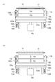
- FIG. 4 is a schematic view showing the movement of the battery cell in the pressing step
- FIG. 5 is a side view showing how the battery cell is cleaned by the battery cleaning device
- FIG. 6 is a schematic view of the battery cleaning device seen from the VI direction of FIG.
- FIG. 7 is a schematic view of the battery cleaning device as seen from the direction VIII in FIG. 4 and 5, only the cleaning roller 102 of the battery cleaning device 100 is shown.
- 6A and 7A show the battery cleaning device during cleaning
- FIGS. 6B and 7B show the battery cleaning device before cleaning.
- the battery cleaning device 100 is applied to a pressing process of pressing the battery cell 10. First, the configuration of the pressing process will be described.
- two transfer devices 50 and 52 that transfer the battery cell 10 with the short sides of the rectangle standing vertically are provided.
- One conveying device 50 suspends the battery cell 10 and conveys it in the air, as shown by a one-dot chain line in FIG.
- the transfer device 50 is, for example, a transfer robot that holds and transfers the outer edge portion (upper side) of the exterior member 13 of the battery cell 10.
- the transport device 52 includes a belt 53 that is formed in a loop and rotates, and a plurality of transport receivers 54 provided on the belt 53.
- the conveyance receiver 54 conveys the battery cell 10 by moving while sandwiching the lower side of the exterior material 13. At least two transport receivers 54 support the battery cell 10.
- the battery cell 10 is transported to the pressing process by the transport device 50 and delivered to the transport device 52.
- the battery cell 10 is picked up and transported to the transport device 50 again.
- a plurality of guide rollers 56 are provided in the pressing process in order to transfer the battery cell 10 between the transfer devices 50 and 52 and to stabilize the transfer of the battery cell 10 during the pressing process.
- the guide rollers 56 are provided on both sides of the battery cell 10 in the conveyance direction, and guide the flat surface 14 of the cell 10 to prevent the battery cell 10 from falling down during the pressing process.
- the pressing roller 60 is disposed in the pressing process. As shown in FIGS. 5 and 6, the pressing roller 60 presses the internal battery element 15 in the stacking direction by pressing the flat surface 14 while sandwiching the battery cell 10 from both sides. Thereby, the gas in the battery element 15 is pushed out of the battery element 15, and the electrolyte solution permeates into the battery element 15 instead.
- a static electricity removing device 62 is provided in the pressing process, accompanying the battery cleaning device 100.
- the static eliminator 62 discharges the battery cell 10 by blowing ions generated at a high frequency onto the flat surface 14 of the battery cell 10.
- the static eliminating device 62 is located behind the cleaning roller 102 and the pressing roller 60 in the traveling direction of the battery cell 10, and removes the flat surface 14 of the battery cell 10 prior to cleaning and pressing.
- the battery cleaning apparatus 100 includes a cleaning roller 102, a transfer roller 104, a roller support portion 106, a cylinder 108, a spring 110, a motor 112, a belt 114, and a fixing portion 116.
- the cleaning roller 102 is an adhesive roller that holds the adhesive material on the surface, and cleans the surface of the battery cell 10 by rotating while contacting the flat surface 14 of the battery cell 10.
- the cleaning roller 102 is located behind the pressing roller 60 in the traveling direction of the battery cell 10 and cleans the flat surface 14 of the battery cell 10 prior to pressing. Further, the cleaning roller 102 is located in front of the static electricity removing device 62 in the traveling direction of the battery cell 10 and cleans the dust from the discharged battery cell 10.
- the transfer roller 104 is a strong adhesive roller that holds an adhesive material having a higher adhesive force than the cleaning roller 102 on its surface and can rotate while contacting the cleaning roller 102. As shown in FIGS. 6 and 7, the transfer roller 104 is arranged side by side with the cleaning roller 102. The transfer roller 104 is in contact with the cleaning roller 102 when the battery cell 10 is being cleaned by the cleaning roller 102, and is separated from the cleaning roller 102 when not cleaning. Details of the approach and separation operations of the cleaning roller 102 and the transfer roller 104 will be described later.
- the roller support unit 106 holds the cleaning roller 102 and the transfer roller 104 rotatably.
- the cleaning roller 102 is held in a long hole 106 h having a rotation shaft provided in the roller support portion 106.
- the long hole 106 h is formed long toward the battery cell 10. Thereby, the cleaning roller 102 can move in a direction toward the battery cell 10 or in a direction away from the battery cell 10.
- the transfer roller 104 is attached to a predetermined position of the roller support portion 106 and is rotatably held at the same position with respect to the roller support portion 106.
- the roller support portion 106 is provided with a pin 106 a that protrudes to the opposite side of the battery cell 10.
- the pin 106 a has a spring holding portion 106 b that holds one end of the spring 110.
- the cylinder 108 has an axis that moves forward or backward toward the battery cell 10, and the axis is fixed to the support plate 108a.
- the pin 106a of the roller support part 106 is penetrated through the support plate 108a.
- a spring holding part 108b that holds one end of the spring 110 is formed on the support plate 108a.
- the pin 106a of the roller support portion 106 is passed through the spring holding portion 108b.
- the spring 110 is attached between the spring holding portion 106b and the spring holding portion 108b described above.
- the spring 110 transmits the power for moving the shaft 108 forward or backward to the roller support 106.
- the support plate 108a is similarly moved.
- the spring holding portion 108b pushes the spring 110 toward the battery cell 10 side.
- the pushed spring 110 pushes the spring holding portion 106b, that is, pushes the pin 106a toward the battery cell 10 side.
- the roller support part 106 also moves to the battery cell 10 side by the movement of the pin 106a. In this way, the movement of the cylinder 108 is transmitted to the roller support portion 106.
- the roller support 106 is also retracted via the spring 110 on the same principle.
- the motor 112 is attached to the support plate 108a.
- the motor 112 has a rotating shaft.
- a belt 114 is attached to the shaft of the motor 112.
- the belt 114 is attached to the rotating shaft of the motor 112 and the rotating shaft of the transfer roller 104. Accordingly, the rotation of the motor 112 is transmitted to the transfer roller 104 via the belt 114.
- the fixing part 116 is attached to a fixing position separately from the roller support part 106 and the like. When the cylinder 108 is retracted, the fixed portion 116 contacts the rotation shaft of the cleaning roller 102 and restricts the movement of the cleaning roller 102.
- the battery cell 10 is transported from the right side to the left side in FIG.
- the position of the battery cell 10 is detected by a sensor (not shown).
- the static eliminator 62 is activated.
- the static eliminator 62 discharges ions from the battery cell 10 by blowing ions onto the flat surfaces 14 on both sides of the battery cell 10.
- the static elimination by the static eliminator 62 is performed until the rear end of the plane 14 passes.
- the battery cleaning device 100 waits at a place away from the plane 14 of the battery cell 10 until the front end of the plane 14 of the battery cell 10 reaches, as shown in FIGS. 6B and 7B. is doing. During standby, the cleaning roller 102 and the transfer roller 104 of the battery cleaning device 100 are separated from each other.
- the battery cleaning device 100 approaches the battery cell 10 as shown in FIGS. 6 (A) and 7 (A).
- the axis of the cylinder 108 advances toward the battery cell 10
- the roller support portion 106 also approaches the battery cell 10.
- the cleaning roller 102 contacts the surface of the battery cell 10.
- the transfer roller 104 comes into contact with the cleaning roller 102.
- the movement of the roller support portion 106 also stops.
- the roller support part 106 is connected to the support plate 108a of the cylinder 108 via the spring 110, it is in a so-called floating state. Thereby, the battery cell 10, the cleaning roller 102, and the transfer roller 104 are contacted with equal force.
- the cleaning roller 102 rotates on the flat surface 14 of the battery cell 10 in the direction indicated by the arrow in FIG. To stick.
- the transfer roller 104 rotates in a direction according to the rotation of the cleaning roller 102. Since the transfer roller 104 has a surface that is more adhesive than the cleaning roller 102, it collects dust on the cleaning roller 102.
- the transfer roller 104 is rotated by the motor 112 in synchronization with the conveyance speed of the battery cell 10.
- the battery cleaning device 100 is separated from the battery cell 10. Specifically, the axis of the cylinder 108 moves backward in the direction away from the battery cell 10, and the roller support 106 also moves in the direction away from the battery cell 10. As the roller support portion 106 moves, the cleaning roller 102 is separated from the battery cell 10. When the roller support portion 106 further moves backward, the rotation shaft of the cleaning roller 102 hits the fixed portion 116. Since the rotation shaft of the cleaning roller 102 is held in the long hole 106h, the cleaning roller 102 is positioned by the fixing portion 116 even if the roller support portion 106 is further retracted.
- the transfer roller 104 Since the transfer roller 104 also moves as the position relative to the roller support portion 106 moves backward, the transfer roller 104 moves away from the cleaning roller 102. When the backward movement of the shaft of the cylinder 108 stops, the movement of the roller support portion 106 also stops. Here, the cleaning roller 102 and the transfer roller 104 are supported by the roller support portion 106 in a state of being separated from each other.
- the pressing roller 60 comes into contact with both flat surfaces 14 of the battery cell 10 as shown in FIG. Roll press on top. Thereby, the battery element 15 in the battery cell 10 is pressed in the stacking direction, the air and gas in the battery element 15 are pushed out, and the electrolytic solution penetrates into the battery element 15.
- the pressing roller 60 continues to press the battery cell 10 until the rear end of the flat surface 14 of the battery cell 10 passes.
- the battery cleaning device 100 cleans the flat surface 14 of the battery cell 10 with the cleaning roller 102 prior to the roll press with the pressing roller 60. Therefore, the dust adhering to the flat surface 14 is not pressed against the battery cell 10 at the time of roll pressing, and the battery cell 10 is not damaged. In addition, since the battery cell 10 can be cleaned in the same pressing process as the roll press, there is no need to provide a separate process for cleaning.
- the cleaning roller 102 is an adhesive roller having an adhesive material attached to the surface, dust on the flat surface 14 can be removed.
- the battery cleaning device 100 is provided with a transfer roller 104 as a strong adhesive roller having higher adhesiveness than the cleaning roller 102.
- a transfer roller 104 comes into contact with the cleaning roller 102, dust collected from the flat surface of the battery cell 10 by the cleaning roller 102 can be adhered. Since the dust on the cleaning roller 102 is collected, when the same part of the cleaning roller 102 contacts the flat surface 14 of the battery cleaning device 100 again, the dust does not return and damage the flat surface 14.
- the cleaning roller 102 can be brought into contact with and act on both flat surfaces 14 of the battery cell 10, it can be efficiently cleaned.
- the transfer roller 104 is driven to rotate in synchronization with the conveyance speed of the battery cell 10 by the rotational power of the motor 112. Therefore, the transfer roller 104 can be rotated regardless of the adhesiveness between the battery cell 10 and the cleaning roller 102 and the adhesiveness between the cleaning roller 102 and the transfer roller 104. As a result, the cleaning roller 102 also rotates smoothly and does not cause a delay in conveying the battery cell 10 due to adhesiveness.
- the transfer roller 104 comes into contact with the cleaning roller 102 and collects dust.
- the transfer roller 104 does not contact the cleaning roller 102. Therefore, it is possible to prevent an unnecessary decrease in adhesiveness due to mutual adhesion between the cleaning roller 102 and the transfer roller 104 in standby.
- both flat surfaces 14 of the battery cell 10 are simultaneously cleaned.
- a mode of cleaning one plane at a time will be described.
- the apparatus configuration is substantially the same. Therefore, in the following, the same reference numerals are assigned to the same configurations as those in the first embodiment, and the duplicate description is omitted.
- FIG. 8 is a schematic view showing the movement of the battery cell in the pressing step.
- two transfer devices 70 and 72 that transfer the battery cell 10 in a state where the plane 14 is up and down, that is, in a so-called flat state, are provided.
- One conveyance device 70 holds the battery cell 10 from above and conveys it in the air.
- the transfer device 70 is, for example, a transfer robot that sucks and transfers the flat surface 14 of the battery cell 10.
- the transport device 70 may be a transport robot that grips and transports the outer edge portion (upper side) of the exterior member 13 of the battery cell 10.
- the transport device 72 slides the transport tray 74 on the slide device 73 and transports it.
- the transfer tray 74 has a recess formed in accordance with the size of the battery cell 10, and transfers the battery cell 10 while positioning the battery cell 10 in the recess.
- the static electricity removing device 62 and the battery cleaning device 100 are disposed on the lower surface side of the battery cell 10.
- the position of the battery cell 10 is confirmed by a sensor (not shown), and the lower surface 14 of the battery cell 10 is discharged by the static electricity removing device 62 and then cleaned by the cleaning roller 102. Although it is from one side, the point which discharges and cleans with respect to the plane 14 of the battery cell 10 is the same as that of 1st Embodiment.
- the battery cell 10 is transferred from the transfer device 70 to the transfer device 72. At this time, the battery cell 10 is placed on the transport tray 74 so that the cleaned lower surface faces the transport tray 74.
- the static electricity removing device 62, the cleaning roller 102, and the pressing roller 60 are disposed on the uncleaned upper surface side of the battery cell 10.
- the position of the battery cell 10 is confirmed by the sensor, the upper surface 14 of the battery cell 10 is discharged by the static eliminator 62, cleaned by the cleaning roller 102, and further the battery cell 10 is roll pressed by the pressing roller 60.
- the pressing roller 60 presses the battery cell 15 in the battery cell 10 by pressing the battery cell 10 against the transport tray 74. Although it is from one side, it is the same as that of 1st Embodiment that the static elimination, cleaning, and roll press are performed with respect to the plane 14 of the battery cell 10.
- FIG. 9 is a schematic view of the battery cleaning device viewed from the IX direction of FIG.
- the battery cleaning device 100 causes the cleaning roller 102 and the transfer roller 104 to approach or separate from the battery cell 10 as the cylinder 108 advances or retracts.
- the transfer roller 104 also contacts the cleaning roller 102.
- the transfer roller 104 moves away from the cleaning roller 102. In this way, one side of the flat surface 14 of the battery cell 10 can be cleaned.
- the battery cleaning device 100 is disposed at a position where the top and bottom of FIG. The configuration is the same.
- the flat surface 14 of the battery cell 10 can be cleaned one side at a time. Since the flat surface 14 facing and hiding the transfer tray 74 is cleaned before the transfer tray 74 is placed, both surfaces of the battery cell 10 can be cleaned. When the battery cell 10 is pressed by the pressing roller 60, there is no dust on the surface of the battery cell 10, and the dust is not pressed against the battery cell 10 to damage the battery cell 10.
- the transfer roller 104 is driven by the motor 112, but in the second embodiment, the motor 112 is omitted. Since the battery cell 10, the cleaning roller 102, and the transfer roller 104 are in contact with each other with equal pressure, the cleaning roller 102 is rotated along with the transfer of the battery cell 10, and the transfer roller 104 is also rotated together. In particular, in the second embodiment, the battery cell 10 is transported while holding the battery cell 10 firmly like the transport device 70 and the transport tray 74, so that the transport delay of the battery cell 10 occurs even if the transfer roller 104 is not driven. do not do.
- a motor 112 may be provided to rotate the transfer roller 104 in accordance with the conveyance speed of the battery cell 10.
- FIG. 10 is a diagram showing a form in which the surface of the battery cell 10 is cleaned by air blowing.
- the battery cleaning apparatus 120 is provided instead of the battery cleaning apparatus 100 containing the cleaning roller 102 as a cleaning means.
- the battery cleaning device 120 blows off dust on the battery cell 10 by blowing air toward the flat surface 14 of the battery cell 10 to clean the battery cell 10.
- the battery cleaning device 120 blows off dust on the battery cell 10 by blowing air toward the flat surface 14 of the battery cell 10 to clean the battery cell 10.
- it is the same as that of 1st and 2nd embodiment.
- FIG. 11 is a schematic view showing a cleaning cell.
- the cleaning roller 102 When there is no transfer roller 104, the cleaning roller 102 needs to be periodically cleaned.
- a cleaning cell 130 shown in FIG. 11 is used.
- the cleaning cell 130 is formed in the same shape as the battery cell 10 by attaching a rubber 134 on a plate member 132.
- An adhesive sheet 136 is attached on the rubber 134.
- the adhesive sheet 136 has higher adhesiveness than the surface of the cleaning roller 102.
- the cleaning cell 130 is transported, and the cleaning roller 102 of the battery cleaning device 100 is brought into contact with the cleaning cell 130. Thereby, the dust attached to the surface of the cleaning roller 102 can be collected in the cleaning cell 130, and the cleaning roller 102 can be cleaned.
- the cleaning roller 102 can be cleaned even when the transfer roller 104 is not provided.
Abstract
The present invention pertains to: a battery cleaning apparatus configured in such a manner as to clean the flat surfaces of a battery cell prior to passing through a roll press so that dust attached to the surfaces does not get pressed against the battery cell when passing through the roll press, damaging the battery cell; and a battery cleaning method. This battery cleaning apparatus has cleaning means (102) for cleaning flat surfaces (14) before passing through the roll press with regard to a battery cell (10) having at least one flat surface (14) that is to be roll pressed.
Description
本発明は、電池押圧装置および電池押圧方法に関する。
The present invention relates to a battery pressing device and a battery pressing method.
近年、様々な製品で電池セルが使用されている。電池セルは、正極、セパレータ、負極が積層された電池要素が外装内に配置されてなる。電池要素は、外装内において、電解液に浸漬されており、化学反応により電力を発生する。
In recent years, battery cells have been used in various products. A battery cell has a battery element in which a positive electrode, a separator, and a negative electrode are stacked and arranged in an exterior. The battery element is immersed in the electrolytic solution in the exterior and generates electric power through a chemical reaction.
このような電池セルを製造する過程においては、外装内に電池要素が配置された状態で、外装内に電解液が注入される。電解液は、電池要素の周りから内部に向かって次第に含浸していく。このため、電池要素の内部に空気が残ってしまう場合がある。
In the process of manufacturing such a battery cell, an electrolytic solution is injected into the exterior in a state where the battery element is disposed in the exterior. The electrolytic solution is gradually impregnated from the periphery of the battery element toward the inside. For this reason, air may remain inside the battery element.
また、電解液を注入した後、化学反応により電解液の一部がガスになって、電池要素の内部に溜まる場合がある。
In addition, after injecting the electrolytic solution, a part of the electrolytic solution may become a gas due to a chemical reaction and collect in the battery element.
そこで、電池セルをロールプレスして、電池要素内部の気体を押し出し、電解液の含浸を高めることが知られている(特許文献1参照)。
Therefore, it is known that the battery cell is roll-pressed to extrude the gas inside the battery element and enhance the impregnation of the electrolytic solution (see Patent Document 1).
しかしながら、ロールプレス工程に電池セルを搬送する途中で、電池セルの表面にゴミが付着する場合がある。電池セルの表面にゴミが付着した状態で、ロールプレスを行うと、ゴミが電池セルの表面を傷つけてしまう虞がある。これでは、外装を被覆するラミネートフィルムが剥がれて金属部分が露出して、電池性能にも影響する可能性がある。
However, dust may adhere to the surface of the battery cell during the transfer of the battery cell to the roll press process. If roll pressing is performed in a state where dust adheres to the surface of the battery cell, the dust may damage the surface of the battery cell. In this case, the laminate film covering the exterior is peeled off and the metal part is exposed, which may affect the battery performance.
本発明は、上記事情に鑑みてなされたものであり、電池セル表面のゴミを除去する電池清掃装置および電池清掃方法を提供することを目的とする。
The present invention has been made in view of the above circumstances, and an object thereof is to provide a battery cleaning device and a battery cleaning method for removing dust on the surface of a battery cell.
ロールプレスされる少なくとも一つの平面を有する電池セルについて、当該ロールプレスの前に、前記平面を清掃する清掃手段を有する電池清掃装置。
A battery cleaning device having cleaning means for cleaning the flat surface of the battery cell having at least one flat surface to be roll pressed before the roll press.
ロールプレスに先立って、電池セルの平面を清掃するので、平面に付着したゴミがロールプレス時に電池セル押しつけられて電池セルが損傷することがない。
Prior to the roll press, the flat surface of the battery cell is cleaned, so that the dust adhering to the flat surface is not pressed during the roll press and the battery cell is not damaged.
以下、添付した図面を参照して、本発明の実施形態を説明する。なお、図面の説明において同一の要素には同一の符号を付し、重複する説明を省略する。また、図面の寸法比率は、説明の都合上誇張されており、実際の比率とは異なる場合がある。
Hereinafter, embodiments of the present invention will be described with reference to the accompanying drawings. In the description of the drawings, the same elements are denoted by the same reference numerals, and redundant description is omitted. In addition, the dimensional ratios in the drawings are exaggerated for convenience of explanation, and may be different from the actual ratios.
本発明は、電池セルの平面を清掃する電池清掃装置および電池清掃方法に関する。電池清掃装置および方法を説明する前に、清掃対象である電池の構造について説明する。
The present invention relates to a battery cleaning device and a battery cleaning method for cleaning a flat surface of a battery cell. Before describing the battery cleaning device and method, the structure of the battery to be cleaned will be described.
(電池)
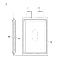
図1は電池セルの外観を表した斜視図、図2は電池セルの平面および側面を示す図、図3は電池セルの分解斜視図である。 (battery)
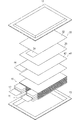
FIG. 1 is a perspective view showing an external appearance of a battery cell, FIG. 2 is a diagram showing a plan and side surfaces of the battery cell, and FIG.
図1は電池セルの外観を表した斜視図、図2は電池セルの平面および側面を示す図、図3は電池セルの分解斜視図である。 (battery)
FIG. 1 is a perspective view showing an external appearance of a battery cell, FIG. 2 is a diagram showing a plan and side surfaces of the battery cell, and FIG.
図1および図2に示すとおり、電池セル10は、扁平な矩形形状を有しており、正極リード11および負極リード12が外装材13の同一端部から導出されている。外装材13は、たとえば、アルミシートの表面を樹脂コーティングしたものである。
1 and 2, the battery cell 10 has a flat rectangular shape, and the positive electrode lead 11 and the negative electrode lead 12 are led out from the same end portion of the exterior material 13. The packaging material 13 is, for example, a resin-coated aluminum sheet surface.
外装材13の内部には、図3に示すように、充放電反応が進行する発電要素(電池要素)15および電解液が収容されている。発電要素15は、間にシート状のセパレータ20を挟みつつ、正極30と、負極40とが交互に積層されて形成される。発電要素15を外装材13内部に配置し電解液を加えた状態や初回充電を行った状態では、電池要素15内部(セパレータ20)に空気やガスなどが溜まることがある。たとえば、図2に点線で示す丸い領域にガスや空気が溜まる。
As shown in FIG. 3, a power generation element (battery element) 15 in which a charge / discharge reaction proceeds and an electrolytic solution are accommodated in the exterior material 13. The power generation element 15 is formed by alternately stacking positive electrodes 30 and negative electrodes 40 with a sheet-like separator 20 interposed therebetween. In a state where the power generation element 15 is disposed inside the exterior member 13 and an electrolytic solution is added or the initial charge is performed, air, gas, or the like may accumulate in the battery element 15 (separator 20). For example, gas and air accumulate in a round area indicated by a dotted line in FIG.
正極30は、シート状の正極集電体の両面に正極活物質層32が形成されてなる。正極活物質層32は、正極30のタブ部分34には形成されていない。正極30の各タブ部分34は、発電要素15の積層方向から見て、重なる位置に設けられている。タブ部分34は、正極リード11と接続される。
The positive electrode 30 has a positive electrode active material layer 32 formed on both surfaces of a sheet-like positive electrode current collector. The positive electrode active material layer 32 is not formed on the tab portion 34 of the positive electrode 30. The tab portions 34 of the positive electrode 30 are provided at overlapping positions when viewed from the stacking direction of the power generation elements 15. The tab portion 34 is connected to the positive electrode lead 11.
負極40は、シート状の負極集電体の両面に負極活物質層42が形成されてなる。負極活物質層42は、負極40のタブ部分44には形成されていない。負極40の各タブ部分44は、発電要素15の積層方向から見て、重なる位置であって、正極30のタブ部分34とは重ならない位置に設けられている。タブ部分44は、負極リード12と接続される。
The negative electrode 40 has a negative electrode active material layer 42 formed on both surfaces of a sheet-like negative electrode current collector. The negative electrode active material layer 42 is not formed on the tab portion 44 of the negative electrode 40. Each tab portion 44 of the negative electrode 40 is provided at a position that overlaps the tab portion 34 of the positive electrode 30 when viewed from the stacking direction of the power generation elements 15. The tab portion 44 is connected to the negative electrode lead 12.
電池セル10は、偏平形の両側に平面14が形成されている。この平面14が後述する押圧ローラにより押圧されることで、電池要素15内部に溜まったガスや空気が電池要素15の外部に押し出され、その代わりに、電解液が電池要素15内まで浸透する。
The battery cell 10 has flat surfaces 14 formed on both sides of the flat shape. When the flat surface 14 is pressed by a pressing roller, which will be described later, the gas and air accumulated in the battery element 15 are pushed out of the battery element 15, and instead, the electrolytic solution penetrates into the battery element 15.
電池清掃装置は、電池セル10を押圧ローラにより押圧する前に、電池セル10の平面14を清掃する。
The battery cleaning device cleans the flat surface 14 of the battery cell 10 before pressing the battery cell 10 with a pressing roller.
以下、電池清掃装置およびその方法について、詳細に説明する。
Hereinafter, the battery cleaning device and the method thereof will be described in detail.
(第1実施形態)
第1実施形態に係る電池清掃装置および電池清掃方法について説明する。 (First embodiment)
A battery cleaning device and a battery cleaning method according to the first embodiment will be described.
第1実施形態に係る電池清掃装置および電池清掃方法について説明する。 (First embodiment)
A battery cleaning device and a battery cleaning method according to the first embodiment will be described.
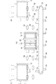
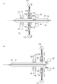
図4は押圧工程における電池セルの動きを示す概略図、図5は電池清掃装置により電池セルを清掃する様子を示す側面図、図6は電池清掃装置を図5のVI方向から見た概略図、図7は電池清掃装置を図5のVIII方向から見た概略図である。なお、図4および図5では、電池清掃装置100のうち、清掃ローラ102だけを示している。また、図6(A)および図7(A)は清掃中の電池清掃装置を示し、図6(B)および図7(B)は清掃前の電池清掃装置を示している。
4 is a schematic view showing the movement of the battery cell in the pressing step, FIG. 5 is a side view showing how the battery cell is cleaned by the battery cleaning device, and FIG. 6 is a schematic view of the battery cleaning device seen from the VI direction of FIG. FIG. 7 is a schematic view of the battery cleaning device as seen from the direction VIII in FIG. 4 and 5, only the cleaning roller 102 of the battery cleaning device 100 is shown. 6A and 7A show the battery cleaning device during cleaning, and FIGS. 6B and 7B show the battery cleaning device before cleaning.
本実施形態では、電池清掃装置100は、電池セル10を押圧する押圧工程に適用される。まず、押圧工程の構成について説明する。
In the present embodiment, the battery cleaning device 100 is applied to a pressing process of pressing the battery cell 10. First, the configuration of the pressing process will be described.
電池セル10を押圧する押圧工程では、矩形の短辺を垂直に立てた状態で電池セル10を搬送する2つの搬送装置50、52が設けられている。一方の搬送装置50は、図4中一点鎖線で示すように、電池セル10を吊り下げて空中搬送する。搬送装置50は、たとえば、電池セル10の外装材13の外縁部分(上辺)を把持して搬送する搬送ロボットである。
In the pressing step of pressing the battery cell 10, two transfer devices 50 and 52 that transfer the battery cell 10 with the short sides of the rectangle standing vertically are provided. One conveying device 50 suspends the battery cell 10 and conveys it in the air, as shown by a one-dot chain line in FIG. The transfer device 50 is, for example, a transfer robot that holds and transfers the outer edge portion (upper side) of the exterior member 13 of the battery cell 10.
また、搬送装置52は、ループ状に形成され回転するベルト53と、ベルト53上に設けられた複数の搬送用受け54とを有する。搬送用受け54は、外装材13の下辺を挟持しつつ移動することによって、電池セル10を搬送する。少なくとも2つの搬送用受け54が、電池セル10を支持する。
The transport device 52 includes a belt 53 that is formed in a loop and rotates, and a plurality of transport receivers 54 provided on the belt 53. The conveyance receiver 54 conveys the battery cell 10 by moving while sandwiching the lower side of the exterior material 13. At least two transport receivers 54 support the battery cell 10.
電池セル10は、搬送装置50により押圧工程まで運ばれ、搬送装置52に受け渡され、押圧工程が終わると、再度搬送装置50にピックアップされて搬出される。搬送装置50、52間の電池セル10の受け渡しや押圧工程中の電池セル10の搬送の安定のために、押圧工程には、複数のガイドローラ56が設けられている。ガイドローラ56は、電池セル10の搬送方向両側に設けられており、セル10の平面14をガイドして、電池セル10が押圧工程を進行中に倒れたりするのを防止する。
The battery cell 10 is transported to the pressing process by the transport device 50 and delivered to the transport device 52. When the pressing process is completed, the battery cell 10 is picked up and transported to the transport device 50 again. A plurality of guide rollers 56 are provided in the pressing process in order to transfer the battery cell 10 between the transfer devices 50 and 52 and to stabilize the transfer of the battery cell 10 during the pressing process. The guide rollers 56 are provided on both sides of the battery cell 10 in the conveyance direction, and guide the flat surface 14 of the cell 10 to prevent the battery cell 10 from falling down during the pressing process.
押圧工程には、押圧ローラ60が配置される。押圧ローラ60は、図5および図6に示すように、電池セル10を両側から挟みつつ平面14を押圧することで、内部の電池要素15を積層方向に押圧する。これにより、電池要素15内の気体が電池要素15外に押し出され、代わりに電解液が電池要素15内に浸透する。
The pressing roller 60 is disposed in the pressing process. As shown in FIGS. 5 and 6, the pressing roller 60 presses the internal battery element 15 in the stacking direction by pressing the flat surface 14 while sandwiching the battery cell 10 from both sides. Thereby, the gas in the battery element 15 is pushed out of the battery element 15, and the electrolyte solution permeates into the battery element 15 instead.
また、図5および図6に示すように、押圧工程には、電池清掃装置100に付随して、静電気除去装置62が設けられる。静電気除去装置62は、高周波で発生させたイオンを電池セル10の平面14に吹きつけて、電池セル10を除電する。静電気除去装置62は、清掃ローラ102および押圧ローラ60に比べて、電池セル10の進行方向の後方に位置し、清掃および押圧に先立って、電池セル10の平面14を除電する。
Further, as shown in FIGS. 5 and 6, a static electricity removing device 62 is provided in the pressing process, accompanying the battery cleaning device 100. The static eliminator 62 discharges the battery cell 10 by blowing ions generated at a high frequency onto the flat surface 14 of the battery cell 10. The static eliminating device 62 is located behind the cleaning roller 102 and the pressing roller 60 in the traveling direction of the battery cell 10, and removes the flat surface 14 of the battery cell 10 prior to cleaning and pressing.
図5~図7に示すように、電池清掃装置100は、清掃ローラ102、転写ローラ104、ローラ支持部106、シリンダ108、バネ110、モータ112およびベルト114および固定部116を有する。
As shown in FIGS. 5 to 7, the battery cleaning apparatus 100 includes a cleaning roller 102, a transfer roller 104, a roller support portion 106, a cylinder 108, a spring 110, a motor 112, a belt 114, and a fixing portion 116.
清掃ローラ102は、粘着材を表面に保持する粘着ローラであり、電池セル10の平面14と接触しながら回転することで、電池セル10の表面を清掃する。清掃ローラ102は、押圧ローラ60よりも、電池セル10の進行方向後方に位置し、押圧に先立って、電池セル10の平面14を清掃する。また、清掃ローラ102は、静電気除去装置62よりも、電池セル10の進行方向前方に位置し、除電された電池セル10について、ゴミを清掃する。
The cleaning roller 102 is an adhesive roller that holds the adhesive material on the surface, and cleans the surface of the battery cell 10 by rotating while contacting the flat surface 14 of the battery cell 10. The cleaning roller 102 is located behind the pressing roller 60 in the traveling direction of the battery cell 10 and cleans the flat surface 14 of the battery cell 10 prior to pressing. Further, the cleaning roller 102 is located in front of the static electricity removing device 62 in the traveling direction of the battery cell 10 and cleans the dust from the discharged battery cell 10.
転写ローラ104は、清掃ローラ102よりも粘着力が高い粘着材を表面に保持し、清掃ローラ102に接触しながら回転できる強粘着ローラである。転写ローラ104は、図6および図7に示すように、清掃ローラ102と並んで配置されている。転写ローラ104は、清掃ローラ102により電池セル10を清掃している際には清掃ローラ102と接触され、清掃していない時には清掃ローラ102から離れる。清掃ローラ102および転写ローラ104の接近、離間の動作について詳細は後述する。
The transfer roller 104 is a strong adhesive roller that holds an adhesive material having a higher adhesive force than the cleaning roller 102 on its surface and can rotate while contacting the cleaning roller 102. As shown in FIGS. 6 and 7, the transfer roller 104 is arranged side by side with the cleaning roller 102. The transfer roller 104 is in contact with the cleaning roller 102 when the battery cell 10 is being cleaned by the cleaning roller 102, and is separated from the cleaning roller 102 when not cleaning. Details of the approach and separation operations of the cleaning roller 102 and the transfer roller 104 will be described later.
ローラ支持部106は、清掃ローラ102および転写ローラ104を回転自在に保持する。清掃ローラ102は、回転軸がローラ支持部106に設けられた長穴106hに保持される。長穴106hは、電池セル10に向かって長く形成されている。これにより、清掃ローラ102は、電池セル10に向かう方向あるいは電池セル10から離れる方向に移動できる。転写ローラ104は、ローラ支持部106の所定位置に取り付けられ、ローラ支持部106に対して同じ位置で回転自在に保持されている。
The roller support unit 106 holds the cleaning roller 102 and the transfer roller 104 rotatably. The cleaning roller 102 is held in a long hole 106 h having a rotation shaft provided in the roller support portion 106. The long hole 106 h is formed long toward the battery cell 10. Thereby, the cleaning roller 102 can move in a direction toward the battery cell 10 or in a direction away from the battery cell 10. The transfer roller 104 is attached to a predetermined position of the roller support portion 106 and is rotatably held at the same position with respect to the roller support portion 106.
ローラ支持部106には、電池セル10の反対側に突出したピン106aが設けられている。ピン106aは、バネ110の一端を保持するバネ保持部106bを有する。
The roller support portion 106 is provided with a pin 106 a that protrudes to the opposite side of the battery cell 10. The pin 106 a has a spring holding portion 106 b that holds one end of the spring 110.
シリンダ108は、電池セル10に向かって進行あるいは後退する軸を有し、当該軸が支持板108aに固定されている。支持板108aは、ローラ支持部106のピン106aが貫通されている。支持板108aには、バネ110の一端を保持するバネ保持部108bが形成されている。バネ保持部108bは、ローラ支持部106のピン106aが貫通されている。
The cylinder 108 has an axis that moves forward or backward toward the battery cell 10, and the axis is fixed to the support plate 108a. The pin 106a of the roller support part 106 is penetrated through the support plate 108a. A spring holding part 108b that holds one end of the spring 110 is formed on the support plate 108a. The pin 106a of the roller support portion 106 is passed through the spring holding portion 108b.
バネ110は、上述のバネ保持部106bおよびバネ保持部108bの間に取り付けられる。バネ110は、シリンダ108の軸の進行または後退の動力を、ローラ支持部106に伝達する。たとえば、シリンダ108の軸が電池セル10に向かって進行されると、支持板108aも同様に移動する。この移動に伴い、バネ保持部108bがバネ110を電池セル10側に押す。押されたバネ110は、バネ保持部106bを押し、つまりピン106aを電池セル10側に押す。ピン106aの移動によりローラ支持部106も電池セル10側に移動する。このように、シリンダ108の動きがローラ支持部106に伝達される。シリンダ108の軸が後退したときも、同様の原理で、バネ110を介して、ローラ支持部106も後退される。
The spring 110 is attached between the spring holding portion 106b and the spring holding portion 108b described above. The spring 110 transmits the power for moving the shaft 108 forward or backward to the roller support 106. For example, when the axis of the cylinder 108 is advanced toward the battery cell 10, the support plate 108a is similarly moved. Along with this movement, the spring holding portion 108b pushes the spring 110 toward the battery cell 10 side. The pushed spring 110 pushes the spring holding portion 106b, that is, pushes the pin 106a toward the battery cell 10 side. The roller support part 106 also moves to the battery cell 10 side by the movement of the pin 106a. In this way, the movement of the cylinder 108 is transmitted to the roller support portion 106. When the axis of the cylinder 108 is retracted, the roller support 106 is also retracted via the spring 110 on the same principle.
モータ112は、支持板108aに取り付けられている。モータ112は回転する軸を有する。モータ112の軸には、ベルト114が取り付けられている。
The motor 112 is attached to the support plate 108a. The motor 112 has a rotating shaft. A belt 114 is attached to the shaft of the motor 112.
ベルト114は、モータ112の回転軸と転写ローラ104の回転軸に取り付けられている。したがって、モータ112の回転は、ベルト114を介して、転写ローラ104に伝達される。
The belt 114 is attached to the rotating shaft of the motor 112 and the rotating shaft of the transfer roller 104. Accordingly, the rotation of the motor 112 is transmitted to the transfer roller 104 via the belt 114.
固定部116は、ローラ支持部106等とは別に、固定位置に取り付けられている。固定部116は、シリンダ108が後退したときには、清掃ローラ102の回転軸と当接し、清掃ローラ102の動きを規制する。
The fixing part 116 is attached to a fixing position separately from the roller support part 106 and the like. When the cylinder 108 is retracted, the fixed portion 116 contacts the rotation shaft of the cleaning roller 102 and restricts the movement of the cleaning roller 102.
(作用)
次に、電池清掃装置100の作用と、押圧ローラ60および静電気除去装置62の作用について、図6および図7を参照して説明する。 (Function)
Next, the operation of thebattery cleaning device 100 and the operation of the pressing roller 60 and the static electricity removing device 62 will be described with reference to FIGS. 6 and 7.
次に、電池清掃装置100の作用と、押圧ローラ60および静電気除去装置62の作用について、図6および図7を参照して説明する。 (Function)
Next, the operation of the
たとえば、図6の紙面右側から左側に電池セル10が搬送されるとする。電池セル10の位置は、図示しないセンサにより検知されている。電池セル10の平面14の進行方向先端が静電気除去装置62の位置に差しかかると、静電気除去装置62が作動する。静電気除去装置62は、電池セル10の両側の平面14にイオンを吹きつけて、電池セル10を除電する。静電気除去装置62による除電は、平面14の後端が通りすぎるまで行われる。
For example, it is assumed that the battery cell 10 is transported from the right side to the left side in FIG. The position of the battery cell 10 is detected by a sensor (not shown). When the leading end of the flat surface 14 of the battery cell 10 reaches the position of the static eliminator 62, the static eliminator 62 is activated. The static eliminator 62 discharges ions from the battery cell 10 by blowing ions onto the flat surfaces 14 on both sides of the battery cell 10. The static elimination by the static eliminator 62 is performed until the rear end of the plane 14 passes.
電池清掃装置100は、電池セル10の平面14の進行方向先端が到達するまでは、図6(B)および図7(B)に示すように、電池セル10の平面14から離れた場所に待機している。なお、待機中には、電池清掃装置100の清掃ローラ102および転写ローラ104は互いに離れている。
The battery cleaning device 100 waits at a place away from the plane 14 of the battery cell 10 until the front end of the plane 14 of the battery cell 10 reaches, as shown in FIGS. 6B and 7B. is doing. During standby, the cleaning roller 102 and the transfer roller 104 of the battery cleaning device 100 are separated from each other.
静電気除去装置62により除電された電池セル10の平面14の先端が到達すると、図6(A)および図7(A)に示すように、電池清掃装置100は、電池セル10に接近する。ここで、詳細には、シリンダ108の軸が電池セル10側に進行して、ローラ支持部106も電池セル10に接近する。まず、清掃ローラ102が電池セル10の表面に接触する。さらに、ローラ支持部106が進行しても、清掃ローラ102は、長穴106hに沿ってローラ支持部106との相対的な位置を変えつつ、電池セル10との相対的な位置を略変えない。ローラ支持部106の移動に従って、転写ローラ104が清掃ローラ102と接触する。シリンダ108の軸の進行が止まると、ローラ支持部106の移動も止まる。ここで、ローラ支持部106は、バネ110を介して、シリンダ108の支持板108aに接続されているので、いわゆるフローティングの状態である。これにより、電池セル10、清掃ローラ102および転写ローラ104間が均等な力で接触される。
When the tip of the flat surface 14 of the battery cell 10 that has been neutralized by the static eliminator 62 arrives, the battery cleaning device 100 approaches the battery cell 10 as shown in FIGS. 6 (A) and 7 (A). Here, in detail, the axis of the cylinder 108 advances toward the battery cell 10, and the roller support portion 106 also approaches the battery cell 10. First, the cleaning roller 102 contacts the surface of the battery cell 10. Further, even when the roller support portion 106 advances, the cleaning roller 102 does not substantially change the relative position with the battery cell 10 while changing the relative position with the roller support portion 106 along the long hole 106h. . As the roller support portion 106 moves, the transfer roller 104 comes into contact with the cleaning roller 102. When the progress of the axis of the cylinder 108 stops, the movement of the roller support portion 106 also stops. Here, since the roller support part 106 is connected to the support plate 108a of the cylinder 108 via the spring 110, it is in a so-called floating state. Thereby, the battery cell 10, the cleaning roller 102, and the transfer roller 104 are contacted with equal force.
電池セル10が図6の紙面左側に送られると、清掃ローラ102は、電池セル10の平面14上を図6中矢印で示す方向に回転しながら、表面の粘着材により電池セル10上のゴミを粘着する。転写ローラ104は、清掃ローラ102の回転に従う方向に回転する。転写ローラ104は、清掃ローラ102よりも粘着性が高い表面を有するので、清掃ローラ102上のゴミを回収する。なお、転写ローラ104は、モータ112により電池セル10の搬送速度と同期して回転されている。
When the battery cell 10 is sent to the left side in FIG. 6, the cleaning roller 102 rotates on the flat surface 14 of the battery cell 10 in the direction indicated by the arrow in FIG. To stick. The transfer roller 104 rotates in a direction according to the rotation of the cleaning roller 102. Since the transfer roller 104 has a surface that is more adhesive than the cleaning roller 102, it collects dust on the cleaning roller 102. The transfer roller 104 is rotated by the motor 112 in synchronization with the conveyance speed of the battery cell 10.
電池セル10の進行方向後端まで清掃が終わると、電池清掃装置100は、電池セル10から離れる。詳細には、シリンダ108の軸が電池セル10から離れる方向に後退して、ローラ支持部106も電池セル10から離れる方向に移動する。ローラ支持部106の移動に伴い清掃ローラ102が電池セル10から離れる。さらにローラ支持部106が後退すると、清掃ローラ102の回転軸が固定部116に当たる。清掃ローラ102の回転軸が長穴106hに保持されているので、さらにローラ支持部106が後退しても、清掃ローラ102は固定部116により位置決めされる。ローラ支持部106との相対的な位置の後退に伴い転写ローラ104も移動するので、転写ローラ104は、清掃ローラ102から離れる。シリンダ108の軸の後退が止まると、ローラ支持部106の移動も止まる。ここで、清掃ローラ102および転写ローラ104は相互に離れた状態でローラ支持部106に支持されている。
When the battery cell 10 has been cleaned up to the rear end in the traveling direction, the battery cleaning device 100 is separated from the battery cell 10. Specifically, the axis of the cylinder 108 moves backward in the direction away from the battery cell 10, and the roller support 106 also moves in the direction away from the battery cell 10. As the roller support portion 106 moves, the cleaning roller 102 is separated from the battery cell 10. When the roller support portion 106 further moves backward, the rotation shaft of the cleaning roller 102 hits the fixed portion 116. Since the rotation shaft of the cleaning roller 102 is held in the long hole 106h, the cleaning roller 102 is positioned by the fixing portion 116 even if the roller support portion 106 is further retracted. Since the transfer roller 104 also moves as the position relative to the roller support portion 106 moves backward, the transfer roller 104 moves away from the cleaning roller 102. When the backward movement of the shaft of the cylinder 108 stops, the movement of the roller support portion 106 also stops. Here, the cleaning roller 102 and the transfer roller 104 are supported by the roller support portion 106 in a state of being separated from each other.
清掃ローラ102により清掃された電池セル10の平面14の先端が押圧ローラ60の位置に到達すると、押圧ローラ60は、図6に示すように、電池セル10の両平面14に当接し、平面14上をロールプレスする。これにより、電池セル10内の電池要素15が積層方向に押圧され、電池要素15内の空気やガスが押し出され、電解液が電池要素15内に浸透する。押圧ローラ60は、電池セル10の平面14の後端が通りすぎるまで、電池セル10の押圧を続ける。
When the tip of the flat surface 14 of the battery cell 10 cleaned by the cleaning roller 102 reaches the position of the pressing roller 60, the pressing roller 60 comes into contact with both flat surfaces 14 of the battery cell 10 as shown in FIG. Roll press on top. Thereby, the battery element 15 in the battery cell 10 is pressed in the stacking direction, the air and gas in the battery element 15 are pushed out, and the electrolytic solution penetrates into the battery element 15. The pressing roller 60 continues to press the battery cell 10 until the rear end of the flat surface 14 of the battery cell 10 passes.
以上のように、第1実施形態の電池清掃装置100によれば、以下の効果が得られる。
As described above, according to the battery cleaning device 100 of the first embodiment, the following effects can be obtained.
電池清掃装置100は、押圧ローラ60によるロールプレスに先立って、清掃ローラ102により電池セル10の平面14を清掃する。したがって、平面14に付着したゴミがロールプレス時に電池セル10押しつけられて電池セル10が損傷することがない。加えて、ロールプレスと同一の押圧工程で電池セル10の清掃ができるので、清掃のために別工程を設ける必要がない。
The battery cleaning device 100 cleans the flat surface 14 of the battery cell 10 with the cleaning roller 102 prior to the roll press with the pressing roller 60. Therefore, the dust adhering to the flat surface 14 is not pressed against the battery cell 10 at the time of roll pressing, and the battery cell 10 is not damaged. In addition, since the battery cell 10 can be cleaned in the same pressing process as the roll press, there is no need to provide a separate process for cleaning.
清掃ローラ102は表面に粘着材が取り付けられた粘着ローラなので、平面14上のゴミを粘着除去できる。
Since the cleaning roller 102 is an adhesive roller having an adhesive material attached to the surface, dust on the flat surface 14 can be removed.
電池清掃装置100には、清掃ローラ102よりも粘着性が強い強粘着ローラとして転写ローラ104が設けられている。転写ローラ104が清掃ローラ102に接触することによって、清掃ローラ102により電池セル10の平面から回収したゴミを粘着できる。清掃ローラ102上のゴミが回収されるので、清掃ローラ102の同じ部分が電池清掃装置100の平面14に再度接触する際に、ゴミが戻って平面14を損傷することがない。
The battery cleaning device 100 is provided with a transfer roller 104 as a strong adhesive roller having higher adhesiveness than the cleaning roller 102. When the transfer roller 104 comes into contact with the cleaning roller 102, dust collected from the flat surface of the battery cell 10 by the cleaning roller 102 can be adhered. Since the dust on the cleaning roller 102 is collected, when the same part of the cleaning roller 102 contacts the flat surface 14 of the battery cleaning device 100 again, the dust does not return and damage the flat surface 14. *
清掃ローラ102は、電池セル10の両平面14に接触し作用できるので、効率よく清掃できる。
Since the cleaning roller 102 can be brought into contact with and act on both flat surfaces 14 of the battery cell 10, it can be efficiently cleaned.
転写ローラ104がモータ112の回転動力により電池セル10の搬送速度と同期して回転駆動される。したがって、電池セル10と清掃ローラ102との間の粘着性および清掃ローラ102と転写ローラ104との間の粘着性に関わらず、転写ローラ104を回転できる。結果として、清掃ローラ102もスムーズに回転し、粘着性による電池セル10の搬送の遅れ等を引き起こさない。
The transfer roller 104 is driven to rotate in synchronization with the conveyance speed of the battery cell 10 by the rotational power of the motor 112. Therefore, the transfer roller 104 can be rotated regardless of the adhesiveness between the battery cell 10 and the cleaning roller 102 and the adhesiveness between the cleaning roller 102 and the transfer roller 104. As a result, the cleaning roller 102 also rotates smoothly and does not cause a delay in conveying the battery cell 10 due to adhesiveness.
清掃ローラ102が電池セル10を清掃している際には、清掃ローラ102に転写ローラ104が接触してゴミを回収する。一方で、清掃ローラ102が電池セル10を清掃しない待機状態の際には、清掃ローラ102に転写ローラ104が接触しない。したがって、待機中の清掃ローラ102および転写ローラ104の相互の粘着による粘着性の不要な低下を防止できる。
When the cleaning roller 102 is cleaning the battery cell 10, the transfer roller 104 comes into contact with the cleaning roller 102 and collects dust. On the other hand, when the cleaning roller 102 is in a standby state where the battery cell 10 is not cleaned, the transfer roller 104 does not contact the cleaning roller 102. Therefore, it is possible to prevent an unnecessary decrease in adhesiveness due to mutual adhesion between the cleaning roller 102 and the transfer roller 104 in standby.
(第2実施形態)
第1実施形態では、電池セル10の両平面14を同時に清掃していた。しかし、第2実施形態では、片方の平面ずつ清掃する形態を説明する。両側からではなく、片側ずつ清掃する点では異なるものの、第1実施形態の電池清掃装置100の一対の清掃ローラ102のうち、片方の清掃ローラ102にだけ着目すると、装置構成は略同一である。したがって、以下では、第1実施形態と同様の構成については、同じ参照番号を付して、重複した説明は省略する。 (Second Embodiment)
In the first embodiment, bothflat surfaces 14 of the battery cell 10 are simultaneously cleaned. However, in the second embodiment, a mode of cleaning one plane at a time will be described. Although it is different in that the cleaning is performed from one side rather than from both sides, when only one of the pair of cleaning rollers 102 of the battery cleaning device 100 of the first embodiment is focused, the apparatus configuration is substantially the same. Therefore, in the following, the same reference numerals are assigned to the same configurations as those in the first embodiment, and the duplicate description is omitted.
第1実施形態では、電池セル10の両平面14を同時に清掃していた。しかし、第2実施形態では、片方の平面ずつ清掃する形態を説明する。両側からではなく、片側ずつ清掃する点では異なるものの、第1実施形態の電池清掃装置100の一対の清掃ローラ102のうち、片方の清掃ローラ102にだけ着目すると、装置構成は略同一である。したがって、以下では、第1実施形態と同様の構成については、同じ参照番号を付して、重複した説明は省略する。 (Second Embodiment)
In the first embodiment, both
図8は、押圧工程における電池セルの動きを示す概略図である。
FIG. 8 is a schematic view showing the movement of the battery cell in the pressing step.
図8に示すように、第2実施形態の押圧工程では、平面14を上下にした状態、いわゆる平置きの状態で電池セル10を搬送する2つの搬送装置70、72が設けられている。一方の搬送装置70は、電池セル10を上方から保持し空中搬送する。搬送装置70は、たとえば、電池セル10の平面14を吸着して搬送する搬送ロボットである。あるいは、搬送装置70は、電池セル10の外装材13の外縁部分(上辺)を把持して搬送する搬送ロボットであってもよい。
As shown in FIG. 8, in the pressing process of the second embodiment, two transfer devices 70 and 72 that transfer the battery cell 10 in a state where the plane 14 is up and down, that is, in a so-called flat state, are provided. One conveyance device 70 holds the battery cell 10 from above and conveys it in the air. The transfer device 70 is, for example, a transfer robot that sucks and transfers the flat surface 14 of the battery cell 10. Alternatively, the transport device 70 may be a transport robot that grips and transports the outer edge portion (upper side) of the exterior member 13 of the battery cell 10.
また、搬送装置72は、スライド装置73上に搬送トレイ74を滑らせて搬送する。搬送トレイ74は、電池セル10の大きさに合せて凹部が形成されており、当該凹部に電池セル10を位置決めしつつ搬送する。
Also, the transport device 72 slides the transport tray 74 on the slide device 73 and transports it. The transfer tray 74 has a recess formed in accordance with the size of the battery cell 10, and transfers the battery cell 10 while positioning the battery cell 10 in the recess.
搬送装置70により空中搬送する工程では、電池セル10の下面側に、静電気除去装置62および電池清掃装置100が配置される。図示しないセンサにより電池セル10の位置が確認され、電池セル10の下側の平面14が静電気除去装置62により除電された上で、清掃ローラ102により清掃される。片面からではあるものの、電池セル10の平面14に対して、除電および清掃する点は、第1実施形態と同様である。
In the step of carrying in the air by the carrying device 70, the static electricity removing device 62 and the battery cleaning device 100 are disposed on the lower surface side of the battery cell 10. The position of the battery cell 10 is confirmed by a sensor (not shown), and the lower surface 14 of the battery cell 10 is discharged by the static electricity removing device 62 and then cleaned by the cleaning roller 102. Although it is from one side, the point which discharges and cleans with respect to the plane 14 of the battery cell 10 is the same as that of 1st Embodiment.
そして、電池セル10は、搬送装置70から搬送装置72に積み替えられる。この際、清掃済の下面が、搬送トレイ74と向き合うように電池セル10が搬送トレイ74に載置される。
Then, the battery cell 10 is transferred from the transfer device 70 to the transfer device 72. At this time, the battery cell 10 is placed on the transport tray 74 so that the cleaned lower surface faces the transport tray 74.
搬送トレイ74に電池セル10が載置されて搬送される押圧工程では、電池セル10の未清掃の上面側に、静電気除去装置62、清掃ローラ102および押圧ローラ60が配置される。センサにより電池セル10の位置が確認され、電池セル10の上側の平面14が静電気除去装置62により除電された上で、清掃ローラ102により清掃され、さらに押圧ローラ60により電池セル10がロールプレスされる。押圧ローラ60は、搬送トレイ74に電池セル10を押しつけることで、電池セル10内の電池要素15を押圧する。片面からではあるものの、電池セル10の平面14に対して、除電、清掃およびロールプレスする点は、第1実施形態と同様である。
In the pressing step in which the battery cell 10 is placed and transported on the transport tray 74, the static electricity removing device 62, the cleaning roller 102, and the pressing roller 60 are disposed on the uncleaned upper surface side of the battery cell 10. The position of the battery cell 10 is confirmed by the sensor, the upper surface 14 of the battery cell 10 is discharged by the static eliminator 62, cleaned by the cleaning roller 102, and further the battery cell 10 is roll pressed by the pressing roller 60. The The pressing roller 60 presses the battery cell 15 in the battery cell 10 by pressing the battery cell 10 against the transport tray 74. Although it is from one side, it is the same as that of 1st Embodiment that the static elimination, cleaning, and roll press are performed with respect to the plane 14 of the battery cell 10.
図9は、電池清掃装置を図8のIX方向から見た概略図である。電池清掃装置100は、第1実施形態と同様に、シリンダ108が進行あるいは後退することで、清掃ローラ102および転写ローラ104を電池セル10に接近または離間させる。電池セル10の平面14に清掃ローラ102が接触する際には、転写ローラ104も清掃ローラ102に接触する。電池セル10の平面14から清掃ローラ102が離れて、電池清掃装置100が待機位置に戻ると、転写ローラ104は清掃ローラ102から離れる。このようにして、電池セル10の平面14の片側を清掃できる。搬送トレイ74に載置された電池セル10の平面14を清掃する場合、電池清掃装置100は、図9の上下を逆転した位置に配置される。構成は同様である。
FIG. 9 is a schematic view of the battery cleaning device viewed from the IX direction of FIG. As in the first embodiment, the battery cleaning device 100 causes the cleaning roller 102 and the transfer roller 104 to approach or separate from the battery cell 10 as the cylinder 108 advances or retracts. When the cleaning roller 102 contacts the flat surface 14 of the battery cell 10, the transfer roller 104 also contacts the cleaning roller 102. When the cleaning roller 102 moves away from the flat surface 14 of the battery cell 10 and the battery cleaning device 100 returns to the standby position, the transfer roller 104 moves away from the cleaning roller 102. In this way, one side of the flat surface 14 of the battery cell 10 can be cleaned. When cleaning the flat surface 14 of the battery cell 10 placed on the transport tray 74, the battery cleaning device 100 is disposed at a position where the top and bottom of FIG. The configuration is the same.
上記第2実施形態のように、電池セル10を平置きして搬送する場合でも、片面ずつ電池セル10の平面14を清掃できる。搬送トレイ74と向き合って隠れてしまう平面14を搬送トレイ74の載置前に清掃しておくので、電池セル10の両面を清掃できる。押圧ローラ60により電池セル10を押圧する際に、電池セル10の表面にゴミがなく、ゴミが電池セル10に押しつけられて電池セル10を破損することがない。
Even when the battery cell 10 is laid flat and transported as in the second embodiment, the flat surface 14 of the battery cell 10 can be cleaned one side at a time. Since the flat surface 14 facing and hiding the transfer tray 74 is cleaned before the transfer tray 74 is placed, both surfaces of the battery cell 10 can be cleaned. When the battery cell 10 is pressed by the pressing roller 60, there is no dust on the surface of the battery cell 10, and the dust is not pressed against the battery cell 10 to damage the battery cell 10.
なお、第1実施形態では、転写ローラ104をモータ112により駆動していたが、第2実施形態ではモータ112を省略している。電池セル10、清掃ローラ102および転写ローラ104は均等な圧力により相互に接しているので、電池セル10の搬送により清掃ローラ102が連れ回り、転写ローラ104も一緒に連れ回る。特に、第2実施形態では、搬送装置70や搬送トレイ74のように、しっかりと電池セル10を保持しながら搬送するので、転写ローラ104を駆動しなくても、電池セル10の搬送遅れは発生しない。もちろん第1実施形態と同様に、モータ112を設けて、転写ローラ104を電池セル10の搬送速度に合せて回転させてもよい。
In the first embodiment, the transfer roller 104 is driven by the motor 112, but in the second embodiment, the motor 112 is omitted. Since the battery cell 10, the cleaning roller 102, and the transfer roller 104 are in contact with each other with equal pressure, the cleaning roller 102 is rotated along with the transfer of the battery cell 10, and the transfer roller 104 is also rotated together. In particular, in the second embodiment, the battery cell 10 is transported while holding the battery cell 10 firmly like the transport device 70 and the transport tray 74, so that the transport delay of the battery cell 10 occurs even if the transfer roller 104 is not driven. do not do. Of course, similarly to the first embodiment, a motor 112 may be provided to rotate the transfer roller 104 in accordance with the conveyance speed of the battery cell 10.
(第3実施形態)
第1実施形態および第2実施形態では、清掃ローラ102を用いて、電池セル10の表面を清掃する形態を説明した。しかし、清掃手段は、これに限定されない。 (Third embodiment)
In 1st Embodiment and 2nd Embodiment, the form which cleans the surface of thebattery cell 10 using the cleaning roller 102 was demonstrated. However, the cleaning means is not limited to this.
第1実施形態および第2実施形態では、清掃ローラ102を用いて、電池セル10の表面を清掃する形態を説明した。しかし、清掃手段は、これに限定されない。 (Third embodiment)
In 1st Embodiment and 2nd Embodiment, the form which cleans the surface of the
図10は、エアブローにより電池セル10の表面を清掃する形態を示す図である。
FIG. 10 is a diagram showing a form in which the surface of the battery cell 10 is cleaned by air blowing.
図10に示すように、第3実施形態では、清掃手段として、清掃ローラ102を含む電池清掃装置100の代わり、電池清掃装置120が設けられる。電池清掃装置120は、電池セル10の平面14に向かって、空気を吹きつけることによって、電池セル10上のゴミを吹き飛ばし電池セル10を清掃する。他の構成については、第1および第2実施形態と同様である。
As shown in FIG. 10, in 3rd Embodiment, the battery cleaning apparatus 120 is provided instead of the battery cleaning apparatus 100 containing the cleaning roller 102 as a cleaning means. The battery cleaning device 120 blows off dust on the battery cell 10 by blowing air toward the flat surface 14 of the battery cell 10 to clean the battery cell 10. About another structure, it is the same as that of 1st and 2nd embodiment.
空気の吹きつけにより電池セル10上のゴミを除去するので、電池セル10に接触せずに平面を清掃できる。
Since dust on the battery cell 10 is removed by blowing air, the plane can be cleaned without contacting the battery cell 10.
(第4実施形態)
第1実施形態および第2実施形態では、清掃ローラ102により粘着したゴミを、転写ローラ104により回収する例を示した。しかし、これに限定されない。転写ローラ104を設けずに、清掃ローラ102のみで電池セル10を清掃してもよい。 (Fourth embodiment)
In the first embodiment and the second embodiment, an example in which dust adhered by the cleaningroller 102 is collected by the transfer roller 104 has been described. However, it is not limited to this. The battery cell 10 may be cleaned only by the cleaning roller 102 without providing the transfer roller 104.
第1実施形態および第2実施形態では、清掃ローラ102により粘着したゴミを、転写ローラ104により回収する例を示した。しかし、これに限定されない。転写ローラ104を設けずに、清掃ローラ102のみで電池セル10を清掃してもよい。 (Fourth embodiment)
In the first embodiment and the second embodiment, an example in which dust adhered by the cleaning
図11は、清掃用セルを示す概略図である。
FIG. 11 is a schematic view showing a cleaning cell.
転写ローラ104がない場合、定期的に清掃ローラ102の清掃が必要となる。清掃ローラ102を清掃する際には、図11に示す清掃用セル130を使用する。清掃用セル130は、たとえば、板材132上にゴム134が取り付けられ、電池セル10と同様の形状に形成される。ゴム134上には、粘着シート136が取り付けられる。粘着シート136は、清掃ローラ102の表面よりも高い粘着性を有する。
When there is no transfer roller 104, the cleaning roller 102 needs to be periodically cleaned. When cleaning the cleaning roller 102, a cleaning cell 130 shown in FIG. 11 is used. For example, the cleaning cell 130 is formed in the same shape as the battery cell 10 by attaching a rubber 134 on a plate member 132. An adhesive sheet 136 is attached on the rubber 134. The adhesive sheet 136 has higher adhesiveness than the surface of the cleaning roller 102.
図4や図8で電池セル10を搬送する代わりに、清掃用セル130を搬送し、電池清掃装置100の清掃ローラ102を清掃用セル130に接触させる。これにより、清掃ローラ102の表面についたゴミを清掃用セル130に回収でき、清掃ローラ102を清掃できる。
4 or 8, instead of transporting the battery cell 10, the cleaning cell 130 is transported, and the cleaning roller 102 of the battery cleaning device 100 is brought into contact with the cleaning cell 130. Thereby, the dust attached to the surface of the cleaning roller 102 can be collected in the cleaning cell 130, and the cleaning roller 102 can be cleaned.
このように、転写ローラ104を設けない場合でも、清掃ローラ102を清掃できる。
Thus, even when the transfer roller 104 is not provided, the cleaning roller 102 can be cleaned.
本出願は、2012年2月13日に出願された日本特許出願番号2012-28487号に基づいており、それらの開示内容は、参照され、全体として、組み入れられている。
This application is based on Japanese Patent Application No. 2012-28487 filed on February 13, 2012, the disclosures of which are referenced and incorporated as a whole.
10 電池セル、
13 外装材、
14 平面、
15 電池要素、
50、52、70、72 搬送装置、
53 ベルト、
56 ガイドローラ、
60 押圧ローラ、
62 静電気除去装置、
73 スライド装置、
74 搬送トレイ、
100、120 電池清掃装置、
102 清掃ローラ、
104 転写ローラ、
106 ローラ支持部、
106a ピン、
106b バネ保持部、
106h 長穴、
108 シリンダ、
108a 支持板、
108b バネ保持部、
110 バネ、
112 モータ、
114 ベルト、
116 固定部、
130 清掃用セル、
132 板材、
134 ゴム、
136 粘着シート。 10 battery cells,
13 Exterior material,
14 plane,
15 battery elements,
50, 52, 70, 72 transport device,
53 belt,
56 guide rollers,
60 pressure roller,
62 Static eliminator,
73 slide device,
74 transport tray,
100, 120 battery cleaning device,
102 cleaning roller,
104 transfer roller,
106 roller support,
106a pin,
106b Spring holding part,
106h slot,
108 cylinders,
108a support plate,
108b Spring holding part,
110 Spring,
112 motor,
114 belts,
116 fixing part,
130 Cleaning cell,
132 plate material,
134 rubber,
136 Adhesive sheet.
Claims (11)
- ロールプレスされる少なくとも一つの平面を有する電池セルについて、当該ロールプレスの前に、前記平面を清掃する清掃手段を有する電池清掃装置。 A battery cleaning device having cleaning means for cleaning the flat surface of the battery cell having at least one flat surface to be roll pressed before the roll press.
- 前記清掃手段は、前記ロールプレスと同一工程において、前記平面を清掃する請求項1記載の電池清掃装置。 The battery cleaning apparatus according to claim 1, wherein the cleaning means cleans the flat surface in the same process as the roll press.
- 前記清掃手段は、粘着材を表面に保持する粘着ローラであり、前記電池セルの平面に回転しながら接触して当該平面を清掃する請求項1または請求項2記載の電池清掃装置。 The battery cleaning device according to claim 1 or 2, wherein the cleaning means is an adhesive roller that holds an adhesive material on a surface thereof, and rotates and contacts the plane of the battery cell to clean the plane.
- 前記粘着ローラよりも粘着力が高い粘着材を表面に保持し、前記粘着ローラに接触しながら回転する強粘着ローラをさらに有する請求項3記載の電池清掃装置。 4. The battery cleaning device according to claim 3, further comprising a strong adhesive roller that holds an adhesive material having a higher adhesive force than the adhesive roller on its surface and rotates while contacting the adhesive roller.
- 前記電池セルは、搬送されており、
前記強粘着ローラは、前記電池セルの搬送速度と同期して回転駆動される請求項4記載の電池清掃装置。 The battery cell is being transported,
The battery cleaning device according to claim 4, wherein the strong adhesion roller is rotationally driven in synchronization with a conveyance speed of the battery cell. - 前記清掃手段は、前記電池セルの平面に空気を吹きつけることによって当該平面を清掃する請求項1または請求項2記載の電池清掃装置。 The battery cleaning apparatus according to claim 1 or 2, wherein the cleaning means cleans the plane by blowing air onto the plane of the battery cell.
- 前記電池セルは、表裏となる両面に前記平面が設けられ、
前記清掃手段は、前記電池セルの両面に向かって一対設けられ、前記両面を同時に清掃する請求項1~6のいずれか一項に記載の電池清掃装置。 The battery cell is provided with the plane on both sides of the front and back,
The battery cleaning device according to any one of claims 1 to 6, wherein a pair of the cleaning means is provided toward both surfaces of the battery cell, and the both surfaces are cleaned simultaneously. - 前記電池セルは、表裏となる両面に前記平面が設けられ、
前記清掃手段は、前記電池セルの一方の面を先に清掃し、当該一方の面が前記電池セルを搬送する搬送手段と向き合うように前記電池セルが当該搬送手段に載置された後で、前記電池セルの他方の面を清掃する請求項1~5のいずれか一項に記載の電池清掃装置。 The battery cell is provided with the plane on both sides of the front and back,
The cleaning means first cleans one surface of the battery cell, and after the battery cell is placed on the transport means so that the one surface faces the transport means for transporting the battery cell, The battery cleaning device according to any one of claims 1 to 5, wherein the other surface of the battery cell is cleaned. - ロールプレスされる少なくとも一つの平面を有する電池セルについて、当該ロールプレスの前に、清掃手段により自動で前記平面を清掃する電池清掃方法。 A battery cleaning method for automatically cleaning a flat surface of a battery cell having at least one flat surface to be roll-pressed by a cleaning means before the roll press.
- 前記清掃手段は、前記ロールプレスと同一工程において、前記平面を清掃する請求項9記載の電池清掃方法。 10. The battery cleaning method according to claim 9, wherein the cleaning means cleans the flat surface in the same process as the roll press.
- 前記清掃手段は、粘着材を表面に保持する粘着ローラであり、前記電池セルの平面に回転しながら接触して当該平面を清掃し、
前記粘着ローラよりも粘着力が高い粘着材を表面に保持する強粘着ローラを、前記粘着ローラに接触させながら回転させて、前記粘着ローラを清掃する請求項9または請求項10記載の電池清掃方法。 The cleaning means is an adhesive roller that holds an adhesive material on the surface, and rotates while contacting the plane of the battery cell to clean the plane.
11. The battery cleaning method according to claim 9, wherein the adhesive roller is cleaned by rotating a strong adhesive roller that holds an adhesive material having an adhesive force higher than that of the adhesive roller on the surface while being in contact with the adhesive roller. .
Priority Applications (3)
| Application Number | Priority Date | Filing Date | Title |
|---|---|---|---|
| CN201380008519.8A CN104106171B (en) | 2012-02-13 | 2013-02-13 | Battery clearing apparatus and battery cleaning method |
| US14/370,088 US20150013720A1 (en) | 2012-02-13 | 2013-02-13 | Battery cleaning device and battery cleaning method |
| EP13748686.6A EP2816650B1 (en) | 2012-02-13 | 2013-02-13 | Battery cleaning apparatus and method |
Applications Claiming Priority (2)
| Application Number | Priority Date | Filing Date | Title |
|---|---|---|---|
| JP2012028487A JP5855483B2 (en) | 2012-02-13 | 2012-02-13 | Battery pressing device and battery pressing method |
| JP2012-028487 | 2012-02-13 |
Publications (1)
| Publication Number | Publication Date |
|---|---|
| WO2013122094A1 true WO2013122094A1 (en) | 2013-08-22 |
Family
ID=48984203
Family Applications (1)
| Application Number | Title | Priority Date | Filing Date |
|---|---|---|---|
| PCT/JP2013/053378 WO2013122094A1 (en) | 2012-02-13 | 2013-02-13 | Battery pressing apparatus and battery pressing method |
Country Status (5)
| Country | Link |
|---|---|
| US (1) | US20150013720A1 (en) |
| EP (1) | EP2816650B1 (en) |
| JP (1) | JP5855483B2 (en) |
| CN (1) | CN104106171B (en) |
| WO (1) | WO2013122094A1 (en) |
Cited By (2)
| Publication number | Priority date | Publication date | Assignee | Title |
|---|---|---|---|---|
| JP2016051647A (en) * | 2014-09-01 | 2016-04-11 | 株式会社豊田自動織機 | Manufacturing method of electrode assembly |
| CN107078334A (en) * | 2014-09-18 | 2017-08-18 | 积水化学工业株式会社 | The manufacture method of secondary cell |
Families Citing this family (10)
| Publication number | Priority date | Publication date | Assignee | Title |
|---|---|---|---|---|
| EP2916372B1 (en) * | 2012-10-30 | 2018-03-28 | Nissan Motor Co., Ltd | Conveyor apparatus |
| JP6394878B2 (en) * | 2014-09-25 | 2018-09-26 | 株式会社豊田自動織機 | Method for manufacturing power storage device |
| JP6481562B2 (en) * | 2015-08-21 | 2019-03-13 | 日産自動車株式会社 | Battery cell storage device |
| KR102135266B1 (en) * | 2017-02-06 | 2020-07-17 | 주식회사 엘지화학 | Apparatus and method for manufacturing battery cell |
| KR102423766B1 (en) * | 2017-07-26 | 2022-07-21 | 삼성전자주식회사 | Three dimensional semiconductor device |
| CN109873192B (en) * | 2017-12-04 | 2020-12-25 | 大族激光科技产业集团股份有限公司 | Battery rolling device |
| KR20200131614A (en) * | 2019-05-14 | 2020-11-24 | 주식회사 엘지화학 | Electrode assembly manufacturing device, electrode assembly manufactured from thereof and rechargeable battery |
| CN112290105B (en) * | 2020-10-28 | 2022-01-28 | 北京中瀚耀明智能科技有限公司 | Lithium ion battery manufacturing process |
| CN112687939B (en) * | 2020-12-28 | 2022-11-01 | 重庆遨博智能科技研究院有限公司 | New energy automobile lithium battery cell snatchs conveying robot |
| CN113275325B (en) * | 2020-12-31 | 2023-05-02 | 浙江工业职业技术学院 | Lithium battery pole piece coiled material targeted dust removal belt pressing mechanism |
Citations (5)
| Publication number | Priority date | Publication date | Assignee | Title |
|---|---|---|---|---|
| JP2002151156A (en) | 2000-11-13 | 2002-05-24 | Toshiba Battery Co Ltd | Method of manufacturing lithium secondary battery |
| JP2005247565A (en) * | 2004-03-08 | 2005-09-15 | Alps Electric Co Ltd | Paper feeding mechanism and printer using this mechanism |
| JP2009300741A (en) * | 2008-06-13 | 2009-12-24 | Konica Minolta Business Technologies Inc | Cleaning roller for transfer belt and image forming apparatus |
| JP2010287545A (en) * | 2009-06-15 | 2010-12-24 | Toyota Motor Corp | Manufacturing method of electrode of battery, manufacturing device, and battery |
| JP2012024658A (en) * | 2010-07-20 | 2012-02-09 | Hitachi Plant Technologies Ltd | Dust removal device for surface of thin film |
Family Cites Families (9)
| Publication number | Priority date | Publication date | Assignee | Title |
|---|---|---|---|---|
| JP2000353513A (en) * | 1999-06-08 | 2000-12-19 | Sony Corp | Cleaning method and cleaning device of battery electrode surface |
| JP5008787B2 (en) * | 2000-04-10 | 2012-08-22 | パナソニック株式会社 | Battery electrode and manufacturing method thereof |
| JP3964886B2 (en) * | 2004-05-24 | 2007-08-22 | 日本ミクロコーティング株式会社 | Panel cleaning apparatus and method |
| CN2766352Y (en) * | 2005-03-01 | 2006-03-22 | 深圳市比克电池有限公司 | Dust-clearing apparatus for battery pole piece |
| US8429787B2 (en) * | 2005-07-27 | 2013-04-30 | Zih Corp. | Dual use cleaning apparatus and method |
| CN101635351B (en) * | 2009-03-11 | 2011-01-26 | 万向电动汽车有限公司 | Method for producing one-sided film pole piece for lithium secondary battery |
| EP2320508B1 (en) * | 2009-10-30 | 2012-09-05 | ads-tec GmbH | Production assembly for a flat battery cell and method for producing a flat battery cell |
| CN201565660U (en) * | 2009-11-04 | 2010-09-01 | 广州兰格电气设备有限公司 | Lithium ion battery full automatic continuous slitting machine |
| TWI408012B (en) * | 2010-02-15 | 2013-09-11 | Bando Chemical Ind | Clean device |
-
2012
- 2012-02-13 JP JP2012028487A patent/JP5855483B2/en active Active
-
2013
- 2013-02-13 CN CN201380008519.8A patent/CN104106171B/en active Active
- 2013-02-13 EP EP13748686.6A patent/EP2816650B1/en active Active
- 2013-02-13 US US14/370,088 patent/US20150013720A1/en not_active Abandoned
- 2013-02-13 WO PCT/JP2013/053378 patent/WO2013122094A1/en active Application Filing
Patent Citations (5)
| Publication number | Priority date | Publication date | Assignee | Title |
|---|---|---|---|---|
| JP2002151156A (en) | 2000-11-13 | 2002-05-24 | Toshiba Battery Co Ltd | Method of manufacturing lithium secondary battery |
| JP2005247565A (en) * | 2004-03-08 | 2005-09-15 | Alps Electric Co Ltd | Paper feeding mechanism and printer using this mechanism |
| JP2009300741A (en) * | 2008-06-13 | 2009-12-24 | Konica Minolta Business Technologies Inc | Cleaning roller for transfer belt and image forming apparatus |
| JP2010287545A (en) * | 2009-06-15 | 2010-12-24 | Toyota Motor Corp | Manufacturing method of electrode of battery, manufacturing device, and battery |
| JP2012024658A (en) * | 2010-07-20 | 2012-02-09 | Hitachi Plant Technologies Ltd | Dust removal device for surface of thin film |
Cited By (7)
| Publication number | Priority date | Publication date | Assignee | Title |
|---|---|---|---|---|
| JP2016051647A (en) * | 2014-09-01 | 2016-04-11 | 株式会社豊田自動織機 | Manufacturing method of electrode assembly |
| CN107078334A (en) * | 2014-09-18 | 2017-08-18 | 积水化学工业株式会社 | The manufacture method of secondary cell |
| EP3196969A4 (en) * | 2014-09-18 | 2018-03-28 | Sekisui Chemical Co., Ltd. | Method for manufacturing secondary battery |
| EP3462530A1 (en) * | 2014-09-18 | 2019-04-03 | Sekisui Chemical Co., Ltd. | Method for manufacturing secondary battery |
| CN107078334B (en) * | 2014-09-18 | 2019-09-13 | 积水化学工业株式会社 | The manufacturing method of secondary cell |
| TWI685998B (en) * | 2014-09-18 | 2020-02-21 | 日商積水化學工業股份有限公司 | Method for producing secondary battery |
| US10637092B2 (en) | 2014-09-18 | 2020-04-28 | Sekisui Chemical Co., Ltd. | Method for manufacturing secondary battery |
Also Published As
| Publication number | Publication date |
|---|---|
| US20150013720A1 (en) | 2015-01-15 |
| EP2816650B1 (en) | 2019-01-02 |
| JP2013165035A (en) | 2013-08-22 |
| JP5855483B2 (en) | 2016-02-09 |
| EP2816650A4 (en) | 2015-10-07 |
| CN104106171B (en) | 2016-09-28 |
| EP2816650A1 (en) | 2014-12-24 |
| CN104106171A (en) | 2014-10-15 |
Similar Documents
| Publication | Publication Date | Title |
|---|---|---|
| JP5855483B2 (en) | Battery pressing device and battery pressing method | |
| WO2017016400A1 (en) | Lithium ion battery lamination device | |
| KR101573588B1 (en) | Position detection device and position detection method | |
| KR101220981B1 (en) | Stacking device for electrode plate of secondary battery | |
| JP5983767B2 (en) | Separator cutting apparatus for electric device and cutting method therefor | |
| CN110808420A (en) | Electrode laminate manufacturing device | |
| KR101504860B1 (en) | Separator welding device and separator welding method | |
| KR20200023852A (en) | Electrode assembly manufacturing equipment | |
| JP6481258B2 (en) | Electric device separator bonding method, electric device separator bonding apparatus, and electric device | |
| KR20130137233A (en) | Device for producing packaged electrode and method for producing bagged electrode | |
| JP2023517563A (en) | Unit cell manufacturing apparatus and method | |
| KR101806939B1 (en) | The processor Play for recycling of expanded polystyrene foam | |
| WO2013122095A1 (en) | Battery pressing apparatus and battery pressing method | |
| KR101504859B1 (en) | Joining device and joining method | |
| JP6063131B2 (en) | Battery pressing device and battery pressing method | |
| JP6717159B2 (en) | Electrode manufacturing equipment | |
| JP6879283B2 (en) | Laminated body manufacturing equipment for sheet-shaped electrodes | |
| KR102253132B1 (en) | Method For Manufacturing Unit Cell of Secondary Cell And The Apparatus And System Using the Same | |
| KR101211781B1 (en) | Label attating device | |
| JP6575118B2 (en) | Electrode laminator | |
| JP2019038674A (en) | Conveyance device | |
| CN215451492U (en) | Lamination device | |
| JP2016120442A (en) | Foreign matter removal method and foreign matter removal device | |
| JP6737172B2 (en) | Electrode inspection device | |
| WO2023190940A1 (en) | Battery electrode manufacturing device and battery electrode manufacturing method |
Legal Events
| Date | Code | Title | Description |
|---|---|---|---|
| 121 | Ep: the epo has been informed by wipo that ep was designated in this application |
Ref document number: 13748686 Country of ref document: EP Kind code of ref document: A1 |
|
| WWE | Wipo information: entry into national phase |
Ref document number: 14370088 Country of ref document: US |
|
| NENP | Non-entry into the national phase |
Ref country code: DE |
|
| WWE | Wipo information: entry into national phase |
Ref document number: 2013748686 Country of ref document: EP |