WO2013122002A1 - Balloon catheter - Google Patents
Balloon catheter Download PDFInfo
- Publication number
- WO2013122002A1 WO2013122002A1 PCT/JP2013/053065 JP2013053065W WO2013122002A1 WO 2013122002 A1 WO2013122002 A1 WO 2013122002A1 JP 2013053065 W JP2013053065 W JP 2013053065W WO 2013122002 A1 WO2013122002 A1 WO 2013122002A1
- Authority
- WO
- WIPO (PCT)
- Prior art keywords
- outer tube
- rear end
- balloon
- balloon catheter
- distal end
- Prior art date
Links
Images


Classifications
-
- A—HUMAN NECESSITIES
- A61—MEDICAL OR VETERINARY SCIENCE; HYGIENE
- A61M—DEVICES FOR INTRODUCING MEDIA INTO, OR ONTO, THE BODY; DEVICES FOR TRANSDUCING BODY MEDIA OR FOR TAKING MEDIA FROM THE BODY; DEVICES FOR PRODUCING OR ENDING SLEEP OR STUPOR
- A61M25/00—Catheters; Hollow probes
- A61M25/10—Balloon catheters
- A61M25/1006—Balloons formed between concentric tubes
-
- A—HUMAN NECESSITIES
- A61—MEDICAL OR VETERINARY SCIENCE; HYGIENE
- A61M—DEVICES FOR INTRODUCING MEDIA INTO, OR ONTO, THE BODY; DEVICES FOR TRANSDUCING BODY MEDIA OR FOR TAKING MEDIA FROM THE BODY; DEVICES FOR PRODUCING OR ENDING SLEEP OR STUPOR
- A61M25/00—Catheters; Hollow probes
- A61M25/10—Balloon catheters
- A61M25/1025—Connections between catheter tubes and inflation tubes
-
- A—HUMAN NECESSITIES
- A61—MEDICAL OR VETERINARY SCIENCE; HYGIENE
- A61M—DEVICES FOR INTRODUCING MEDIA INTO, OR ONTO, THE BODY; DEVICES FOR TRANSDUCING BODY MEDIA OR FOR TAKING MEDIA FROM THE BODY; DEVICES FOR PRODUCING OR ENDING SLEEP OR STUPOR
- A61M25/00—Catheters; Hollow probes
- A61M25/10—Balloon catheters
- A61M25/1027—Making of balloon catheters
- A61M25/1034—Joining of shaft and balloon
Definitions
- the present invention relates to a balloon catheter, and more particularly to a balloon catheter that is inserted into a small-diameter body cavity such as a blood vessel or a bile duct.
- the balloon catheter is used for angiography, injection of a chemical solution such as a chemotherapeutic agent, embolization, percutaneous coronary artery dilatation (PTCA), percutaneous arterial dilatation (PTA) and the like.
- a chemical solution such as a chemotherapeutic agent, embolization, percutaneous coronary artery dilatation (PTCA), percutaneous arterial dilatation (PTA) and the like.
- PTCA percutaneous coronary artery dilatation
- PTA percutaneous arterial dilatation
- the balloon catheter 1 of Patent Document 1 includes a double-tube catheter main body 3 including an inner tube 9 and an outer tube 21.
- a balloon 7 is attached to the distal end portion of the catheter body, and an infusate passage 23 formed between the inner tube and the outer tube is communicated with the balloon 7 through the distal end opening 22 of the outer tube.
- Balloon catheters such as Patent Document 1 have recently been required to be inserted into thinner blood vessels, and in order to improve blood vessel insertion, changes in physical properties at the distal end are gentle. It is desirable that
- an object of the present invention is to provide an inner tube, an outer tube that is provided coaxially with the inner tube, protrudes from the distal end of the inner tube, a balloon having a distal end fixed to the inner tube and a rear end fixed to the outer tube.
- a balloon catheter that has a gentle change in physical properties at the fixing portion between the balloon and the outer tube, prevents kinking caused by the two, and improves the operability of insertion into the body cavity A catheter is provided.
- An inner tube having a first lumen and a second lumen provided coaxially with the inner tube, having a tip at a position retracted by a predetermined length from the tip of the inner tube, and the outer surface of the inner tube
- a balloon catheter comprising: an outer tube having a distal end fixed to the inner tube; a rear end fixed to the distal end of the outer tube; and an expandable balloon having an interior communicating with the second lumen
- the balloon has an expandable portion formed on the rear end side from the tip portion, and a tubular shape formed between the expandable portion and the rear end portion and extending a predetermined length in the rear end direction.
- the rear end portion includes an inclined rear end surface that is inclined with respect to the central axis of the cylindrical portion, and the distal end portion of the outer tube is positioned on the central axis of the outer tube.
- An inclined tip surface that is slanted with respect to the tip of the outer tube and the balloon.
- the end portion has a portion that overlaps in the axial direction of the balloon catheter, and the distal end portion of the outer tube and the rear end portion of the balloon are provided in the overlapping portion, and are arranged on the central axis of the outer tube.
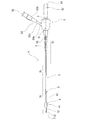
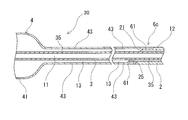
- FIG. 1 is a partially omitted external view of an embodiment of a balloon catheter according to the present invention.
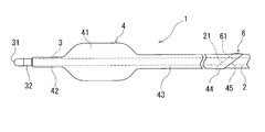
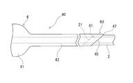
- FIG. 2 is an enlarged external view of the distal end portion of the balloon catheter shown in FIG.
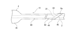
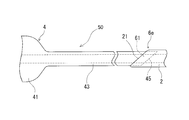
- FIG. 3 is a longitudinal sectional view of FIG. 4 is an enlarged longitudinal sectional view of a proximal end portion of the balloon catheter shown in FIG.
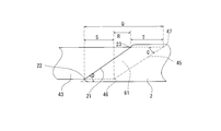
- FIG. 5 is an explanatory view for explaining a fixing portion between the balloon rear end portion and the outer tube front end portion of the balloon catheter of the present invention.
- FIG. 6 is an explanatory view for explaining a fixing portion between the balloon rear end portion and the outer tube front end portion of the balloon catheter of the present invention.
- FIG. 1 is a partially omitted external view of an embodiment of a balloon catheter according to the present invention.
- FIG. 2 is an enlarged external view of the distal end portion of the balloon catheter shown in FIG.
- FIG. 7 is an explanatory view for explaining a fixing portion between the balloon rear end portion and the outer tube front end portion of the balloon catheter of the present invention.
- FIG. 8 is an enlarged external view of the vicinity of a fixing portion between a balloon rear end portion and an outer tube front end portion of a balloon catheter according to another embodiment of the present invention.
- FIG. 9 is a longitudinal sectional view of FIG.
- FIG. 10 is an enlarged external view of the vicinity of a fixing portion between a balloon rear end portion and an outer tube front end portion of a balloon catheter according to another embodiment of the present invention.
- FIG. 11 is a longitudinal sectional view of FIG. FIG.
- FIG. 12 is an enlarged cross-sectional view of the vicinity of a fixing portion between a balloon rear end portion and an outer tube front end portion of a balloon catheter according to another embodiment of the present invention.
- FIG. 13 is an enlarged external view of the vicinity of a fixing portion between a balloon rear end portion and an outer tube front end portion of a balloon catheter according to another embodiment of the present invention.
- FIG. 14 is a longitudinal sectional view of FIG.
- FIG. 15 is an enlarged external view of the vicinity of a fixing portion between a balloon rear end portion and an outer tube front end portion of a balloon catheter according to another embodiment of the present invention.
- 16 is a longitudinal sectional view of FIG.
- FIG. 17 is an explanatory diagram for explaining a fixing portion between a balloon rear end portion and an outer tube front end portion of a balloon catheter according to another embodiment of the present invention.
- the balloon catheter of the present invention will be described with reference to the embodiments shown in the drawings.
- the balloon catheter 1 of the present invention is provided with an inner tube 3 having a first lumen 11, and coaxially with the inner tube 3, and has a distal end at a position retracted by a predetermined length from the distal end of the inner tube 3.
- the outer tube 2 forming the second lumen 12 between the outer tube 2 and the outer tube 2, the front end 42 is fixed to the inner tube 3, the rear end 44 is fixed to the outer tube 2, and the inner portion is connected to the second lumen 12.
- an expandable balloon 4 in communication therewith.
- the balloon 4 has an expandable portion 41 formed on the rear end side of the front end portion 42, and a tubular portion (between the expandable portion 41 and the rear end portion 44 and extending a predetermined length in the rear end direction.
- Sleeve 43, and the rear end portion 44 includes an inclined rear end surface 45 that is inclined with respect to the central axis of the cylindrical portion 43.
- the distal end portion of the outer tube 2 includes an inclined distal end surface 21 that is inclined with respect to the central axis of the outer tube 2.
- the distal end portion of the outer tube 2 and the rear end portion 44 of the balloon 4 have a portion overlapping in the axial direction of the balloon catheter 1, and the distal end portion of the outer tube 2 and the rear end portion 44 of the balloon 4 overlap each other. It is fixed by a belt-like inclined annular fixing portion 6 provided in the portion, inclined with respect to the central axis of the outer tube 2 and formed airtight.
- the balloon catheter 1 of this embodiment is formed by an outer tube 2, an inner tube 3, a balloon 4 and a branch hub 5.
- the inner tube 3 is a tube body having a first lumen 11 whose tip is open.
- the first lumen 11 is used for insertion of a guide wire, injection of a chemical solution, and the like.
- the first lumen 11 of the inner tube 3 communicates with the first opening 54 provided in the branch hub 5.
- the inner tube 3 preferably has an outer diameter of 0.60 to 1.63 mm, particularly preferably 0.62 to 0.68 mm, and an inner diameter of 0.40 to 1.33 mm. And particularly preferably 0.43 to 0.50 mm.
- the inner tube 3 is inserted into the outer tube 2, and the tip of the inner tube 3 protrudes from the outer tube 2.
- a second lumen (balloon expansion lumen) 12 is formed between the outer surface of the inner tube 3 and the inner surface of the outer tube 2 and has a sufficient volume.
- a contrast marker 32 is fixed to the distal end (slightly proximal side of the distal end 31, near the distal end 42 of the balloon 4).
- the contrast marker is preferably formed of a radiopaque material (for example, gold, platinum, tungsten, or an alloy thereof, or a silver-palladium alloy, a platinum-iridium alloy, or the like).
- a radiopaque material for example, gold, platinum, tungsten, or an alloy thereof, or a silver-palladium alloy, a platinum-iridium alloy, or the like.
- the most flexible first flexible region 3a extends from the distal end of the inner tube 3 in the rear end direction, and the rear end of the first flexible region 3a is an outer portion to be described later. It passes over the belt-like inclined annular fixing portion 6 between the tube 2 and the cylindrical portion of the balloon 4 and is located on the rear end side of a predetermined length.
- the length of the first region 3a is preferably 100 to 350 mm, and particularly preferably 200 to 300 mm.
- the hardness of the first region 3a is preferably 30 to 40D (Shore D hardness).
- the length of the second flexible region 3b that is continuous with the first flexible region 3a is preferably 100 to 350 mm, and particularly preferably 200 to 300 mm.
- the hardness of the second region 3a is preferably 40 to 55D (Shore D hardness), and preferably 5 to 15D (Shore D hardness) higher than the first flexible region.
- the length of the third region 3c continuous with the second flexible region 3b is preferably 500 to 1500 mm, and particularly preferably 800 to 1200 mm.
- the hardness of the third region 3c is preferably 55 to 85D (Shore D hardness), and preferably 15 to 40D (Shore D hardness) hardness higher than that of the second flexible region.
- the outer tube 2 is a tube body that is inserted in the inner tube 3 and located at a portion (predetermined length base end side) whose tip is retracted by a predetermined length from the tip of the inner tube 3.
- the distal end of the second lumen 12 communicates with the rear end portion of the balloon 4 to be described later, and the rear end of the second lumen 12 is provided on the branch hub 5 and is a fluid for inflating the balloon (for example, the balloon It communicates with the second opening 55 of the injection port 53 for injecting an expansion liquid (specifically, an angiographic agent).
- the outer tube 2 preferably has an outer diameter of 0.85 to 2.03 mm, particularly preferably 0.87 to 0.95 mm, and an inner diameter of 0.70 to 1.83 mm. And particularly preferably 0.72 to 0.80 mm.
- the outer tube 2 includes an inclined distal end surface 21 that is inclined with respect to the central axis of the outer tube 2 at the distal end.
- the material for forming the outer tube 2 and the inner tube 3 is preferably a material having a certain degree of hardness and a certain degree of flexibility.
- polyolefins such as polyethylene and polypropylene
- polyamides such as polyamide and polyethylene terephthalate
- PTFE Fluorine-based polymers such as ETFE, PEEK (polyetheretherketone), polyimide
- olefin-based elastomer for example, polyethylene elastomer, polypropylene elastomer
- polyamide elastomer for example, polyethylene elastomer, polypropylene elastomer
- polyamide elastomer for example, styrene-based elastomer (for example, styrene-butadiene-styrene copolymer, styrene) -Isoprene-styrene copolymer, styrene-ethylenebutylene-s
- the outer tube 2 and the inner tube 3 may be provided with a rigidity imparting body 35.
- a rigidity imparting body a blade formed of a metal wire or a synthetic resin wire is preferable.
- an expandable one, a foldable one, an expandable and foldable one, or the like is used.
- the balloon can be folded on the outer periphery of the inner tube 3 and can be restored to a molded form and expanded (expanded) by the balloon expanding fluid. It is used.
- the material for forming the balloon 4 include polyolefin, polyvinyl chloride, polyamide, polyester, polyarylene sulfide, and the like, and synthetic resin elastomers such as polyamide elastomer, polyester elastomer, and urethane elastomer, silicone rubber, latex rubber, and the like. The rubber material can be used.
- polyurethane-based thermoplastic elastomers for example, aromatic polyurethane-based thermoplastic elastomers, aliphatic polyurethane-based thermoplastic elastomers, etc. are preferred.
- polyurethane-based thermoplastic elastomers include aromatic and aliphatic thermoplastic elastomer polyurethanes. It is done.
- the balloon 4 has higher flexibility and flexibility than the outer tube 2. In particular, the balloon 4 is preferably higher in flexibility and flexibility than the inner tube 3 and the outer tube 2.
- the balloon 4 has an expandable part 41 formed on the rear end side from the front end part 42, and a cylindrical part (in other words, formed between the expandable part 41 and the rear end part 44 and extending a predetermined length in the rear end direction. ), And the rear end portion 44 includes an inclined rear end surface 45 that is inclined with respect to the central axis of the cylindrical portion 43.
- the rear end portion 44 of the balloon 4 and the distal end portion of the outer tube 2 are fixed by a band-shaped inclined annular fixing portion 6 that is inclined with respect to the central axis of the outer tube 2 and is hermetically formed.
- the distal end portion 42 of the balloon 4 is a cylindrical portion that extends a predetermined length from the distal end of the expandable portion 41 and is fixed to the distal end portion of the inner tube 3.
- the distal end portion 42 of the balloon 4 has a smaller outer diameter than the cylindrical portion (sleeve) 43 provided on the rear end side from the expandable portion 41.
- the tip end of the distal end portion 42 of the balloon 4 is located at the rear end of the contrast marker 32 or close without reaching the rear end. Further, it is preferable that the distal end portion 42 of the balloon 4 does not cover the contrast marker 32.
- the distal end portion 42 of the balloon 4 is preferably fixed to the inner tube 3 by heat sealing.
- the expandable portion 41 is expanded by the injected liquid and can be in close contact with the inner wall of a body cavity (specifically, a blood vessel).
- the distal end portion 42 is a short cylindrical portion extending with substantially the same outer diameter.
- the cylindrical portion 43 formed between the expandable portion 41 and the rear end portion 44 extends with substantially the same outer diameter, and has a length longer in the axial direction than the front end portion 42.
- the cylindrical portion 43 forms a passage 13 that communicates with the second lumen 12 by the inner surface and the inner surface of the inner tube 3.
- the outer diameter of the expandable portion 41 at the time of maximum expansion is preferably 3.0 to 15.0 mm, and particularly preferably 4.0 to 8.0 mm.
- the length of the expandable portion 41 is preferably 3.5 to 14.5 mm, and particularly preferably 4.0 to 5.5 mm.
- the outer diameter of the tip 42 is preferably 0.77 to 1.85 mm, particularly preferably 0.80 to 0.90 mm, and the length is 1.0 to 3.0 mm. It is preferably 1.5 to 2.5 mm.
- the outer diameter of the cylindrical portion 43 is preferably 0.90 to 2.10 mm, particularly preferably 0.93 to 1.00 mm, and the length is preferably 10 to 60 mm. Particularly preferred is 15 to 30 mm.
- the expandable part 41 of the balloon 4 is thinner than the tip part 42 and the cylindrical part 43, and is easy to expand and expand with the expansion liquid to be injected.
- the wall thickness of the expandable portion 41 is preferably 0.03 to 0.18 mm thinner than the tubular portion 43 and the tip portion 42, and particularly preferably 0.04 to 0.11 mm thinner.
- the thickness of the cylindrical portion 43 and the tip portion 42 is preferably 0.07 to 0.20 mm, and particularly preferably 0.08 to 0.15 mm.
- the inclined annular fixing portion 6 (in other words, the inclined annular joint portion) for joining the rear end portion 44 of the balloon 4 and the distal end portion of the outer tube 2 in the balloon catheter of this embodiment will be described with reference to FIGS. To do.
- the distal end portion of the outer tube 2 includes the inclined distal end surface 21 that is inclined with respect to the central axis of the outer tube 2, and the balloon 4 is disposed at the rear end portion 44 with respect to the central axis of the tubular portion 43. And an inclined rear end face 45 that is slanted.
- pipe 2 and the rear-end part 44 of the balloon 4 have a part which overlaps with the axial direction of a balloon catheter.
- a belt-shaped inclined annular fixing portion 6 provided at an overlapping portion of the distal end portion of the outer tube 2 and the rear end portion 44 of the balloon 4 and inclined with respect to the central axis of the outer tube 2 and formed airtight.
- the outer tube 2 and the balloon 4 are fixed by the inclined annular fixing portion 6. Since the cylindrical portion 43 and the rear end portion 44 of the balloon 4 are more flexible and flexible than the distal end portion of the outer tube 2, the inclined annular fixing portion 6 is formed from the rear end side to the distal end side. Flexibility toward the side increases. Therefore, a sharp property change point in the vicinity of the distal end portion of the outer tube 2 is not formed, and the occurrence of kinks is prevented and the film has good deformability.
- the rear end portion 44 of the balloon 4 is an enlarged diameter portion (in other words, an inclined enlarged diameter portion, an inclined bulging portion), and the rear end face 45 is a cylindrical portion. It is an inclined rear end face inclined by a predetermined angle with respect to the central axis of 43 (outer tube 2).
- the distal end portion of the outer tube 2 enters the rear end portion 44 whose diameter has been increased, and this entering portion forms a portion where the distal end portion of the outer tube 2 and the rear end portion 44 of the balloon 4 overlap.
- the outer tube 2 has substantially the same outer diameter as the cylindrical portion 43 of the balloon 4, and the rear end portion 44 of the balloon 4 is in a bulged state.
- the inclined rear end surface 45 of the balloon 4 and the inclined front end surface 21 of the outer tube 2 are substantially parallel or have different inclination angles with respect to the central axis of the outer tube. 44 degrees or less, preferably 20 degrees or less.
- an inclination angle A with respect to the central axis of the cylindrical portion 43 (outer tube 2) of the inclined rear end surface 45 of the balloon 4 is relative to the central axis of the outer tube 2 of the inclined distal end surface 21 of the outer tube 2. It is preferable that the inclination angle B is large.
- the inclination angle A of the inclined rear end face 45 of the balloon 4 with respect to the central axis of the tubular portion 43 (outer tube 2) is preferably 20 degrees to 30 degrees, and more preferably 22 degrees to 28 degrees.
- the inclination angle B of the inclined tip surface 21 of the outer tube 2 with respect to the central axis of the outer tube 2 is preferably 30 to 45 degrees, and particularly preferably 35 to 43 degrees.
- FIG. 6 The inclined annular fixing portion 6 has an annular fixing surface 61.
- the annular fixing portion 61 is formed on the entire inner surface of the proximal end portion 44 of the balloon 4 that contacts the outer surface of the distal end portion of the outer tube 2 of the inclined annular fixing portion 6.
- a non-fixed portion that does not affect the airtightness between the two may be included. It is preferable that the annular fixing portion 61 has substantially the same width or gradually becomes wider toward the rear end. In the balloon catheter 1 of this embodiment, as shown in FIG. 6, the annular fixing portion 61 is gradually widened toward the rear end.
- the imaginary line connecting the tip 22 of the inclined distal end surface 21 of the outer tube 2 and the tip 46 of the inclined rear end surface 45 of the balloon 4 is substantially parallel to the central axis of the outer tube 2. It has become.
- the distal end 22 of the inclined distal end surface 21 of the outer tube 2 is positioned substantially in front of the distal end 46 of the inclined rear end surface 45 of the balloon 4.
- an imaginary line connecting the rear end 23 of the inclined distal end surface 21 of the outer tube 2 and the rear end 47 of the inclined rear end surface 46 of the balloon 4 is substantially parallel to the central axis of the outer tube 2.
- the rear end 23 of the inclined front end surface 21 of the outer tube 2 is positioned substantially in front of the rear end 47 of the rear end surface 45 of the balloon 4 in the front end direction. For this reason, a narrow portion is not formed in the annular fixing portion 61.
- the tip 46 of the inclined rear end surface 45 of the balloon 4 is located on the front end side from the rear end 23 of the inclined front end surface 21 of the outer tube 2.
- the physical property of the inclined annular fixing portion 6 continuously changes. Since the cylindrical portion 43 and the rear end portion 44 of the balloon 4 are more flexible and flexible than the distal end portion of the outer tube 2, the inclined annular fixing portion 6 is formed from the rear end side to the distal end side. Flexibility and softness gradually increase toward the side.
- the portion where the rear end portion of the balloon 4 covers the front end portion of the outer tube 2 is increased from the rear end side, and the rear end of the inclined front end surface 21 of the outer tube 2 is increased.
- the rear end portion 44 of the balloon 4 continues to increase in cross-sectional area perpendicular to the axial direction, but decreases in cross-sectional area perpendicular to the axial direction of the distal end portion of the outer tube 2.
- tip 46 of the inclined surface 45 of the rear-end part 44 of the balloon 4 the cross section of the rear-end part 44 becomes cyclic
- tip part of the outer tube 2 reduces the cross-sectional area in the front, Terminate at the tip 22.
- the inclined annular fixing portion 6 is entirely formed on the cutting surface orthogonal to the central axis of the outer tube 2 so that the rear end portion 44 of the balloon 4 and the distal end portion of the outer tube 2 are both annular. It is something that has no part.
- the distance P between the distal end 22 of the outer tube 2 and the distal end 46 of the inclined rear end face 45 of the balloon 4 in FIG. 6 is preferably 0.50 to 1.50 mm, particularly 0.6 to 1.0 mm. It is preferable that The distance N between the rear end 23 of the inclined front end surface 21 of the outer tube 2 and the rear end 47 of the inclined rear end surface 45 of the balloon 4 is preferably 0.50 to 4.0 mm, particularly 0.6. It is preferable that the thickness is ⁇ 1.0 mm.
- the axial length L of the inclined annular fixing portion 6 (in other words, the distance L between the distal end 22 of the outer tube 2 and the rear end 47 of the inclined rear end face 45 of the balloon 4) is 2.0 to 8.0 mm.
- the thickness is preferably 2.3 to 3.5 mm.
- the distance M between the rear end 23 of the inclined front end surface 21 of the outer tube 2 and the front end 46 of the inclined rear end surface 45 of the balloon 4 is preferably 0.6 to 2.5 mm, particularly 0.8 to It is preferable that it is 1.5 mm.
- the distance M between the rear end 23 of the inclined distal end surface 21 of the outer tube 2 and the distal end 46 of the inclined rear end surface 45 of the balloon 4 is 0, that is, the inclined distal end of the outer tube 2 as in the embodiment shown in FIG.
- the rear end 23 of the surface 21 and the tip 46 of the inclined rear end surface 45 of the balloon 4 may be located at the same position in the axial direction of the outer tube 2.
- the rear end 23 of the inclined front end surface 21 of the outer tube 2 is preferably not located on the front end side of the front end 46 of the inclined rear end surface 45 of the balloon 4.
- the inclined annular fixing portion 6 is heated to an overlapped portion and about 2 mm before and after the end portion of the outer tube 2 is inserted into the rear end portion 44 of the balloon 4.
- the shrinkable tube is fitted, and the heat shrinkable tube is heated from the outer surface by the heat mold 7 so as to be fused together.
- the outer edge of the inclined front end surface of the outer tube 2 is rounded with no edges due to melting.
- fusion part with the rear-end part of the balloon 4 can be formed in the front-end
- the joining form of the rear end portion of the balloon 4 and the front end portion of the outer tube 2 is not limited to the above-described one, but the type provided in the balloon catheter 10 of the embodiment shown in FIGS. 8 and 9. It may be.
- the distal end portion of the outer tube 2 is an inclined small diameter portion 25, and an inclined distal end surface 21 is formed at the distal end thereof.
- the outer diameter of the rear end portion 44 of the balloon 4 is substantially the same as the outer diameter of the outer tube main body portion on the proximal end side from the inclined small diameter portion of the outer tube 2.
- the inclined small-diameter portion of the outer tube 2 is inserted and fixed in the inclined rear end portion 44 of the balloon 4 to form the inclined annular fixing portion 6a.
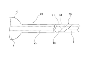
- the rear end portion 44 of the balloon 4 is an inclined bulging portion, and the rear end side thereof extends to the rear end portion of the outer tube 2 with substantially the same outer diameter. It has become. Further, the joint end of the balloon 4 and the outer tube 2 exposed on the outer surface of the catheter 10 does not have a step. Further, the joining form of the rear end portion of the balloon 4 and the distal end portion of the outer tube 2 may be of the type provided in the balloon catheter 20 of the embodiment shown in FIGS. 10 and 11.
- the rear end portion of the balloon 4 is not an inclined diameter-expanded portion, and is formed by extending the tubular portion 43 as it is and terminating obliquely.
- pipe 2 is equipped with the inclination small diameter part 25 and the thick part 24 following it.
- An inclined tip surface 21 is formed at the tip of the inclined small diameter portion 25.
- the outer diameter of the outer tube main body portion on the proximal end side from the inclined small diameter portion of the outer tube 2 is substantially the same as the outer diameter of the cylindrical portion 43 and the rear end portion of the balloon 4.
- the inclined small-diameter portion 25 of the outer tube 2 is inserted and fixed in the inclined rear end portion of the balloon 4 to form the inclined annular fixing portion 6b.
- the rear end side of the expandable portion 41 of the balloon 4 extends to the rear end portion of the outer tube 2 with substantially the same outer diameter.
- the outer tube 2 may have an entire inner diameter extending to the rear end portion with the inner diameter of the inclined small diameter portion 25.
- the inclined distal end portion of the outer tube 2 is inserted into the inclined rear end portion of the balloon 4 and fixed, thereby forming the inclined annular fixing portion 6c.
- the joining form of the rear end portion of the balloon 4 and the distal end portion of the outer tube 2 may be of the type provided in the balloon catheter 40 of the embodiment shown in FIGS. 13 and 14.
- the rear end portion of the balloon 4 is not an inclined diameter-expanded portion, and is formed by extending the tubular portion 43 as it is and terminating obliquely.
- the outer tube 2 extends to the rear end with an outer diameter that can be inserted into the rear end of the balloon 4.
- the inclined tip end portion of the outer tube 2 is inserted into the inclined rear end portion of the balloon 4 and fixed, thereby forming the inclined annular fixing portion 6d.
- the inclined annular fixing portion 6d has an inclined step, but the outer diameter of the outer tube 2 is small.
- the joining form of the rear end portion of the balloon 4 and the distal end portion of the outer tube 2 may be of the type provided in the balloon catheter 50 of the embodiment shown in FIGS. 15 and 16.
- the distal end portion of the outer tube 2 is inserted into the rear end portion of the balloon 4, but in the balloon catheter 50 of this embodiment, the outer tube is conversely arranged.
- the inclined rear end portion of the balloon 4 is inserted into the two inclined front end portions, and this insertion portion forms a portion where the front end portion of the outer tube 2 and the rear end portion 44 of the balloon 4 overlap.
- fixed part 6e is formed by fixing this overlapping part.
- the distal end portion of the outer tube 2 includes an inclined distal end surface 21 that is inclined with respect to the central axis of the outer tube 2, and the balloon 4 has a tubular portion 43 at the rear end portion 44.
- An inclined rear end face 45 that is inclined with respect to the central axis is provided.
- pipe 2 and the rear-end part 44 of the balloon 4 are being fixed with the belt-shaped inclined cyclic
- the inclined annular fixing portion 6e is formed from the rear end side to the front end portion. Flexibility toward the side increases. Therefore, a sharp property change point in the vicinity of the distal end portion of the outer tube 2 is not formed, preventing the occurrence of kinks and maintaining good deformability.
- the outer diameter of the outer tube 2 is substantially the same as the outer diameter of the cylindrical portion 43 of the balloon 4, and the catheter 50 is expanded in diameter at the outer tube portion.
- the inclined rear end surface 45 of the balloon 4 and the inclined front end surface 21 of the outer tube 2 are substantially parallel or have different inclination angles with respect to the central axis of the outer tube. However, it is 44 degrees or less, preferably 20 degrees or less.
- the inclination angle C of the inclined rear end face 45 of the balloon 4 with respect to the central axis of the tubular portion 43 (outer tube 2) is preferably 35 degrees to 65 degrees, and particularly preferably 40 degrees to 50 degrees.
- the inclination angle D of the inclined distal end surface 21 of the outer tube 2 with respect to the central axis of the outer tube 2 is preferably 15 degrees to 35 degrees, and more preferably 20 degrees to 30 degrees.
- the rear end portion of the balloon 4 that has entered the front end portion of the outer tube 2 is airtightly fixed to the outer tube 2 and forms a belt-like inclined annular fixing portion 6e.
- the inclined annular fixing part 6 e has an annular fixing surface 61.
- the annular fixing portion 61 is formed on the entire inner surface of the base end portion 44 of the balloon 4 that contacts the outer surface of the distal end portion of the outer tube 2 of the inclined annular fixing portion 6e.
- the annular fixing portion 61 has substantially the same width or gradually becomes wider toward the rear end.
- the annular fixing portion 61 is gradually widened toward the rear end.
- the phantom line connecting the tip 22 of the inclined front end surface 21 of the outer tube 2 and the tip 46 of the inclined rear end surface 45 of the balloon 4 is 2 is almost parallel to the central axis.
- the distal end 22 of the inclined distal end surface 21 of the outer tube 2 is positioned substantially in front of the distal end 46 of the inclined rear end surface 45 of the balloon 4.
- an imaginary line connecting the rear end 23 of the inclined distal end surface 21 of the outer tube 2 and the rear end 47 of the inclined rear end surface 46 of the balloon 4 is substantially parallel to the central axis of the outer tube 2. That is, the rear end 23 of the inclined front end surface 21 of the outer tube 2 is positioned substantially in front of the rear end 47 of the rear end surface 45 of the balloon 4 in the front end direction. For this reason, a narrow portion is not formed in the annular fixing portion 61.
- the tip 46 of the inclined rear end surface 45 of the balloon 4 is located on the front end side from the rear end 23 of the inclined front end surface 21 of the outer tube 2.
- the rear end 23 of the inclined front end surface 21 of the outer tube 2 and the front end 46 of the inclined rear end surface 45 of the balloon 4 may be located at the same position in the axial direction of the outer tube 2.
- the physical property of the inclined annular fixing portion 6e continuously changes. Since the cylindrical portion 43 and the rear end portion 44 of the balloon 4 are higher in flexibility and flexibility than the distal end portion of the outer tube 2, the inclined annular fixing portion 6e is formed from the rear end side to the front end portion. Flexibility and softness gradually increase toward the side.
- the portion where the distal end portion of the outer tube 2 covers the rear end portion of the balloon 4 increases from the rear end side, and the rear end of the inclined distal end surface 21 of the outer tube 2 increases.
- the rear end portion 44 of the balloon 4 continues to increase in cross-sectional area perpendicular to the axial direction, but decreases in cross-sectional area perpendicular to the axial direction of the distal end portion of the outer tube 2.
- the cross section of the rear-end part 44 becomes cyclic
- tip part of the outer tube 2 reduces the cross-sectional area in the front, Terminate at the tip 22.
- the inclined annular fixing portion 6e is entirely annular on the cut surface perpendicular to the central axis of the outer tube 2 so that the rear end portion 44 of the balloon 4 and the distal end portion of the outer tube 2 are both annular. It is something that has no part.
- the distance S between the distal end 22 of the outer tube 2 and the distal end 46 of the inclined rear end face 45 of the balloon 4 in FIG. 17 is preferably 0.5 to 7.0 mm, particularly 0.6 to 1.0 mm. It is preferable that The distance T between the rear end 23 of the inclined front end surface 21 of the outer tube 2 and the rear end 47 of the inclined rear end surface 45 of the balloon 4 is preferably 0.5 to 2.5 mm, particularly 0.65. It is preferably ⁇ 1.00 mm.
- the axial length Q of the inclined annular fixing portion 6e (in other words, the distance between the distal end 22 of the outer tube 2 and the rear end 47 of the inclined rear end face 45 of the balloon 4) is 2.0 to 11.6 mm.
- the thickness is preferably 2.2 to 3.5 mm.
- the distance R between the rear end 23 of the inclined front end face 21 of the outer tube 2 and the front end 46 of the inclined rear end face 45 of the balloon 4 is preferably 0.7 to 2.1 mm, particularly 0.9 to It is preferable that it is 1.5 mm.
- the branch hub 5 includes a first opening 54 that communicates with the first lumen 11, an inner tube hub 52 fixed to the rear end portion of the inner tube 3, and a second
- the outer tube hub 51 and the inner tube hub 52 are provided with an outer tube hub 51 that has a second opening 55 that communicates with the lumen 12 and forms an injection port 53 and is fixed to the rear end of the outer tube 2.
- the outer tube hub 51 and the inner tube hub 52 are fixed by inserting and joining the inner tube 3 from the rear end of the outer tube hub 51 attached to the base end portion of the outer tube 2.
- the branch hub 5 is provided with a bending prevention tube 56 that encloses the proximal end portion of the outer tube 2 and the distal end portion of the branch hub 5.
- the injection port 53 is formed by a branch port 53a extending from the side wall of the outer pipe hub 51, an injection port hub 53b, and a connection tube 53c that connects the branch port 53a and the injection port hub 53b.
- a material for forming the branch hub thermoplastic resins such as polycarbonate, polyamide, polysulfone, polyarylate, and methacrylate-butylene-styrene copolymer can be preferably used.
- the connection tube a flexible or soft synthetic resin tube is used.
- the structure of the balloon catheter is not limited to the one described above, and has a guide wire insertion port that communicates with the guide wire lumen in the middle portion of the balloon catheter (the rear end side from the inclined annular fixing portion 6). It may be a thing.
- the balloon catheter of the present invention is preferably applied to a catheter for drug administration with a vascular occlusion function, but is not limited thereto, and can be applied to a PTCA catheter, a balloon expandable stent delivery system, and the like. it can.
- the balloon catheter of the present invention is as follows. (1) An inner tube having a first lumen, and provided coaxially with the inner tube, having a tip at a position retracted by a predetermined length from the tip of the inner tube, and between the outer surface of the inner tube An outer tube forming two lumens, an expandable balloon having a distal end fixed to the inner tube, a rear end fixed to the distal end of the outer tube, and an interior communicating with the second lumen.
- the balloon catheter includes an expandable portion formed on the rear end side of the tip portion, and formed between the expandable portion and the rear end portion, and has a predetermined length in the rear end direction.
- the rear end portion includes an inclined rear end surface that is inclined with respect to the central axis of the cylindrical portion, and the front end portion of the outer tube is formed of the outer tube.
- the rear end portion of the balloon catheter has a portion overlapping in the axial direction of the balloon catheter, and the distal end portion of the outer tube and the rear end portion of the balloon are provided in the overlapping portion,
- a balloon catheter which is fixed by a belt-like inclined annular fixing portion which is inclined with respect to the central axis and is formed airtight.
- the balloon since the balloon has a cylindrical portion extending in the predetermined long axis direction between the expandable portion and the rear end portion, the distal end side of the outer tube is made low profile (the diameter is reduced when inserted into the living body). This makes it easy to insert into a smaller body cavity (for example, a blood vessel), and the physical properties of the fixed part between the rear end of the balloon and the distal end of the outer tube change gradually. A portion where the physical properties change suddenly near the distal end of the tube and near the proximal end of the balloon is not formed, and kinks due to the change in physical properties are less likely to occur, and the insertion into the body cavity is easy.
- the following may be sufficient.
- the inclination angle of the inclined front end surface of the outer tube with respect to the central axis of the outer tube is larger than the inclination angle of the inclined rear end surface of the balloon with respect to the central axis of the outer tube.
- the tip of the inclined rear end surface of the balloon is located at the same position in the axial direction as the rear end of the inclined distal end surface of the outer tube or the tip end side in the axial direction (1) to (7)
- the balloon catheter according to any one of the above. (9) Any of (1) to (8) above, wherein the balloon catheter includes a first opening communicating with the first lumen and a second opening communicating with the second lumen.
- the balloon catheter according to 1. (10)
- the balloon catheter includes a hub fixed to proximal ends of the inner tube and the outer tube, and the hub includes the first opening and the second opening. The balloon catheter according to).
Abstract
Provided is a balloon catheter (1) comprising an inner tube (3), an outer tube (2), and a balloon (4) having a tip section (42) that is fixed to the inner tube (3) and a rear end section (44) that is attached to the external tube (2). The balloon (4) comprises an expandable section (41), a cylindrical section (43) that is positioned between the expandable section (41) and the rear end section (44) and that extends to a predetermined length, and an inclined rear end surface (45) that is inclined with respect to the central axis of the cylindrical section (43). The tip section of the outer tube (2) comprises an inclined tip surface (21) that is inclined with respect to the central axis of the outer tube (2). The tip section of the outer tube (2) and the rear end section of the balloon (4) are fixed together by means of an inclined annular fixing section (6) that is formed on the parts of the two sections that overlap with one another, is inclined with respect to the central axis of the outer tube, and is formed to have a band shape that is airtight.
Description
本発明は、バルーンカテーテル、特に、血管、胆管などの細径の体腔内に挿入されるバルーンカテーテルに関する。
The present invention relates to a balloon catheter, and more particularly to a balloon catheter that is inserted into a small-diameter body cavity such as a blood vessel or a bile duct.
バルーンカテーテルは、血管造影、化学療法剤等の薬液注入、塞栓術、経皮冠動脈拡張術(PTCA)、経皮的動脈拡張術(PTA)等に使用されている。
バルーンカテーテルとしては、本願出願人が提案する特許文献1(特開2005-103120)がある。
特許文献1のバルーンカテーテル1は、インナーチューブ9とアウターチューブ21とを備えた二重管構造のカテーテル本体3を備える。カテーテル本体の先端部にバルーン7が取り付けられ、その内部に、インナーチューブとアウターチューブとの間に形成された注入液通路23がアウターチューブの先端開口22を介して連通している。 The balloon catheter is used for angiography, injection of a chemical solution such as a chemotherapeutic agent, embolization, percutaneous coronary artery dilatation (PTCA), percutaneous arterial dilatation (PTA) and the like.
As a balloon catheter, there is JP-A-2005-103120 proposed by the applicant of the present application.
Theballoon catheter 1 of Patent Document 1 includes a double-tube catheter main body 3 including an inner tube 9 and an outer tube 21. A balloon 7 is attached to the distal end portion of the catheter body, and an infusate passage 23 formed between the inner tube and the outer tube is communicated with the balloon 7 through the distal end opening 22 of the outer tube.
バルーンカテーテルとしては、本願出願人が提案する特許文献1(特開2005-103120)がある。
特許文献1のバルーンカテーテル1は、インナーチューブ9とアウターチューブ21とを備えた二重管構造のカテーテル本体3を備える。カテーテル本体の先端部にバルーン7が取り付けられ、その内部に、インナーチューブとアウターチューブとの間に形成された注入液通路23がアウターチューブの先端開口22を介して連通している。 The balloon catheter is used for angiography, injection of a chemical solution such as a chemotherapeutic agent, embolization, percutaneous coronary artery dilatation (PTCA), percutaneous arterial dilatation (PTA) and the like.
As a balloon catheter, there is JP-A-2005-103120 proposed by the applicant of the present application.
The
上記特許文献1のような、バルーンカテーテルは、最近では、より細い血管への挿入が求められるようになってきており、血管挿入を良好なものとするために、先端部における物性の変化がなだらかであることが望ましい。
Balloon catheters such as Patent Document 1 have recently been required to be inserted into thinner blood vessels, and in order to improve blood vessel insertion, changes in physical properties at the distal end are gentle. It is desirable that
そこで、本発明の目的は、内管と、内管と同軸的に設けられ、内管の先端より突出する外管と、先端部が内管に、後端部が外管に固定されたバルーンとを備えるバルーンカテーテルであって、バルーンと外管との固定部における物性の変化をなだらかなものとし、両者間に起因するキンクを防止するとともに、体腔内への挿入操作性を向上させたバルーンカテーテルを提供する。
Accordingly, an object of the present invention is to provide an inner tube, an outer tube that is provided coaxially with the inner tube, protrudes from the distal end of the inner tube, a balloon having a distal end fixed to the inner tube and a rear end fixed to the outer tube. A balloon catheter that has a gentle change in physical properties at the fixing portion between the balloon and the outer tube, prevents kinking caused by the two, and improves the operability of insertion into the body cavity A catheter is provided.
上記目的を達成するものは、以下のものである。
第1のルーメンを有する内管と、前記内管と同軸的に設けられ、前記内管の先端より所定長後退した位置に先端を有し、前記内管の外面との間に第2のルーメンを形成する外管と、先端部が前記内管に固定され、後端部が前記外管の先端部に固定され、内部が前記第2のルーメンと連通する拡張可能なバルーンとを備えるバルーンカテーテルであって、前記バルーンは、前記先端部より前記後端部側に形成された拡張可能部と、前記拡張可能部と前記後端部間に形成され、後端部方向に所定長延びる筒状部とを備え、かつ、前記後端部は、前記筒状部の中心軸に対して斜めである傾斜後端面を備えており、前記外管の前記先端部は、前記外管の中心軸に対して斜めである傾斜先端面を備えており、前記外管の前記先端部と前記バルーンの前記後端部は、前記バルーンカテーテルの軸方向に重なり合う部分を有し、さらに、前記外管の前記先端部と前記バルーンの前記後端部は、前記重なり合う部分に設けられ、前記外管の中心軸に対して傾斜し、かつ気密に形成された帯状の傾斜環状固定部により固定されているバルーンカテーテル。 What achieves the above object is as follows.
An inner tube having a first lumen and a second lumen provided coaxially with the inner tube, having a tip at a position retracted by a predetermined length from the tip of the inner tube, and the outer surface of the inner tube A balloon catheter comprising: an outer tube having a distal end fixed to the inner tube; a rear end fixed to the distal end of the outer tube; and an expandable balloon having an interior communicating with the second lumen The balloon has an expandable portion formed on the rear end side from the tip portion, and a tubular shape formed between the expandable portion and the rear end portion and extending a predetermined length in the rear end direction. And the rear end portion includes an inclined rear end surface that is inclined with respect to the central axis of the cylindrical portion, and the distal end portion of the outer tube is positioned on the central axis of the outer tube. An inclined tip surface that is slanted with respect to the tip of the outer tube and the balloon The end portion has a portion that overlaps in the axial direction of the balloon catheter, and the distal end portion of the outer tube and the rear end portion of the balloon are provided in the overlapping portion, and are arranged on the central axis of the outer tube. A balloon catheter fixed by a band-shaped inclined annular fixing portion that is inclined and airtight.
本発明のバルーンカテーテルを図面に示した実施例を用いて説明する。
本発明のバルーンカテーテル1は、第1のルーメン11を有する内管3と、内管3と同軸的に設けられ、内管3の先端より所定長後退した位置に先端を有し、内管3の外面との間に第2のルーメン12を形成する外管2と、先端部42が内管3に固定され、後端部44が外管2に固定され、内部が第2のルーメン12と連通する拡張可能なバルーン4とを備える。そして、バルーン4は、先端部42より後端部側に形成された拡張可能部41と、拡張可能部41と後端部44間に形成され、後端部方向に所定長延びる筒状部(スリーブ)43とを備え、かつ、後端部44は、筒状部43の中心軸に対して斜めである傾斜後端面45を備える。外管2の先端部は、外管2の中心軸に対して斜めである傾斜先端面21を備える。そして、外管2の先端部とバルーン4の後端部44は、バルーンカテーテル1の軸方向に重なり合う部分を有し、さらに、外管2の先端部とバルーン4の後端部44は、重なり合う部分に設けられ、外管2の中心軸に対して傾斜し、かつ気密に形成された帯状の傾斜環状固定部6により固定されている。 The balloon catheter of the present invention will be described with reference to the embodiments shown in the drawings.
Theballoon catheter 1 of the present invention is provided with an inner tube 3 having a first lumen 11, and coaxially with the inner tube 3, and has a distal end at a position retracted by a predetermined length from the distal end of the inner tube 3. The outer tube 2 forming the second lumen 12 between the outer tube 2 and the outer tube 2, the front end 42 is fixed to the inner tube 3, the rear end 44 is fixed to the outer tube 2, and the inner portion is connected to the second lumen 12. And an expandable balloon 4 in communication therewith. The balloon 4 has an expandable portion 41 formed on the rear end side of the front end portion 42, and a tubular portion (between the expandable portion 41 and the rear end portion 44 and extending a predetermined length in the rear end direction. Sleeve) 43, and the rear end portion 44 includes an inclined rear end surface 45 that is inclined with respect to the central axis of the cylindrical portion 43. The distal end portion of the outer tube 2 includes an inclined distal end surface 21 that is inclined with respect to the central axis of the outer tube 2. The distal end portion of the outer tube 2 and the rear end portion 44 of the balloon 4 have a portion overlapping in the axial direction of the balloon catheter 1, and the distal end portion of the outer tube 2 and the rear end portion 44 of the balloon 4 overlap each other. It is fixed by a belt-like inclined annular fixing portion 6 provided in the portion, inclined with respect to the central axis of the outer tube 2 and formed airtight.
本発明のバルーンカテーテル1は、第1のルーメン11を有する内管3と、内管3と同軸的に設けられ、内管3の先端より所定長後退した位置に先端を有し、内管3の外面との間に第2のルーメン12を形成する外管2と、先端部42が内管3に固定され、後端部44が外管2に固定され、内部が第2のルーメン12と連通する拡張可能なバルーン4とを備える。そして、バルーン4は、先端部42より後端部側に形成された拡張可能部41と、拡張可能部41と後端部44間に形成され、後端部方向に所定長延びる筒状部(スリーブ)43とを備え、かつ、後端部44は、筒状部43の中心軸に対して斜めである傾斜後端面45を備える。外管2の先端部は、外管2の中心軸に対して斜めである傾斜先端面21を備える。そして、外管2の先端部とバルーン4の後端部44は、バルーンカテーテル1の軸方向に重なり合う部分を有し、さらに、外管2の先端部とバルーン4の後端部44は、重なり合う部分に設けられ、外管2の中心軸に対して傾斜し、かつ気密に形成された帯状の傾斜環状固定部6により固定されている。 The balloon catheter of the present invention will be described with reference to the embodiments shown in the drawings.
The
この実施例のバルーンカテーテル1は、外管2と、内管3と、バルーン4と、分岐ハブ5とにより形成されている。
内管3は、先端が開口した第1のルーメン11を有するチューブ体である。第1のルーメン11は、ガイドワイヤーの挿通、薬液等の注入などに使用される。そして、この実施例のバルーンカテーテル1では、内管3の第1のルーメン11は、分岐ハブ5に設けられた第1の開口部54と連通している。 Theballoon catheter 1 of this embodiment is formed by an outer tube 2, an inner tube 3, a balloon 4 and a branch hub 5.
Theinner tube 3 is a tube body having a first lumen 11 whose tip is open. The first lumen 11 is used for insertion of a guide wire, injection of a chemical solution, and the like. In the balloon catheter 1 of this embodiment, the first lumen 11 of the inner tube 3 communicates with the first opening 54 provided in the branch hub 5.
内管3は、先端が開口した第1のルーメン11を有するチューブ体である。第1のルーメン11は、ガイドワイヤーの挿通、薬液等の注入などに使用される。そして、この実施例のバルーンカテーテル1では、内管3の第1のルーメン11は、分岐ハブ5に設けられた第1の開口部54と連通している。 The
The
内管3としては、外径が、0.60~1.63mmであることが好ましく、特に好ましくは、0.62~0.68mmであり、内径が、0.40~1.33mmであることが好ましく、特に好ましくは、0.43~0.50mmである。
そして、内管3は、外管2の内部に挿通され、その先端部が外管2より突出している。この内管3の外面と外管2の内面間により第2のルーメン(バルーン拡張用ルーメン)12が形成されており、十分な容積を有している。 Theinner tube 3 preferably has an outer diameter of 0.60 to 1.63 mm, particularly preferably 0.62 to 0.68 mm, and an inner diameter of 0.40 to 1.33 mm. And particularly preferably 0.43 to 0.50 mm.
Theinner tube 3 is inserted into the outer tube 2, and the tip of the inner tube 3 protrudes from the outer tube 2. A second lumen (balloon expansion lumen) 12 is formed between the outer surface of the inner tube 3 and the inner surface of the outer tube 2 and has a sufficient volume.
そして、内管3は、外管2の内部に挿通され、その先端部が外管2より突出している。この内管3の外面と外管2の内面間により第2のルーメン(バルーン拡張用ルーメン)12が形成されており、十分な容積を有している。 The
The
そして、内管3には、先端部(先端31より若干基端側、バルーン4の先端部42付近)に造影マーカー32が固定されている。造影マーカーは、X線不透過材料(例えば、金、白金、タングステン若しくはそれらの合金、あるいは銀-パラジウム合金、白金-イリジウム合金等)により形成することが好ましい。このようにすることにより、バルーンカテーテル1の先端部をX線造影により確認することができる。
また、この実施例のものでは、図1に示すように、内管3は、先端側より、柔軟な第1柔軟領域3aと、第1領域3aと連続し、柔軟であるが第1柔軟領域3aより硬度が高い第2柔軟領域3bと、第2柔軟領域3bと連続し、第2柔軟領域3bより硬度が高い第3領域3cを有している。特に、この実施例では、最も柔軟な第1柔軟領域3aは、図1に示すように、内管3の先端より、後端方向に延び、第1柔軟領域3aの後端は、後述する外管2とバルーン4の筒状部との帯状の傾斜環状固定部6を越え、所定長後端側に位置するものとなっている。第1領域3aの長さとしては、100~350mmが好ましく、特に、200~300mmが好ましい。また、第1領域3aの硬度は、30~40D(ショアD硬度)であることが好ましい。また、第1柔軟領域3aと連続する第2柔軟領域3bの長さとしては、100~350mmが好ましく、特に、200~300mmが好ましい。また、第2領域3aの硬度は、40~55D(ショアD硬度)であることが好ましく、第1柔軟領域より、5~15D(ショアD硬度)硬度が高いことが好ましい。また、第2柔軟領域3bと連続する第3領域3cの長さとしては、500~1500mmが好ましく、特に、800~1200mmが好ましい。また、第3領域3cの硬度は、55~85D(ショアD硬度)であることが好ましく、第2柔軟領域より、15~40D(ショアD硬度)硬度が高いことが好ましい。 In theinner tube 3, a contrast marker 32 is fixed to the distal end (slightly proximal side of the distal end 31, near the distal end 42 of the balloon 4). The contrast marker is preferably formed of a radiopaque material (for example, gold, platinum, tungsten, or an alloy thereof, or a silver-palladium alloy, a platinum-iridium alloy, or the like). By doing in this way, the front-end | tip part of the balloon catheter 1 can be confirmed by X-ray contrast.
Further, in this embodiment, as shown in FIG. 1, theinner tube 3 is continuous with the first flexible region 3a and the first region 3a from the distal end side, and is flexible, but the first flexible region. A second flexible region 3b having a hardness higher than 3a and a third region 3c that is continuous with the second flexible region 3b and has a hardness higher than that of the second flexible region 3b. In particular, in this embodiment, as shown in FIG. 1, the most flexible first flexible region 3a extends from the distal end of the inner tube 3 in the rear end direction, and the rear end of the first flexible region 3a is an outer portion to be described later. It passes over the belt-like inclined annular fixing portion 6 between the tube 2 and the cylindrical portion of the balloon 4 and is located on the rear end side of a predetermined length. The length of the first region 3a is preferably 100 to 350 mm, and particularly preferably 200 to 300 mm. The hardness of the first region 3a is preferably 30 to 40D (Shore D hardness). The length of the second flexible region 3b that is continuous with the first flexible region 3a is preferably 100 to 350 mm, and particularly preferably 200 to 300 mm. The hardness of the second region 3a is preferably 40 to 55D (Shore D hardness), and preferably 5 to 15D (Shore D hardness) higher than the first flexible region. Further, the length of the third region 3c continuous with the second flexible region 3b is preferably 500 to 1500 mm, and particularly preferably 800 to 1200 mm. The hardness of the third region 3c is preferably 55 to 85D (Shore D hardness), and preferably 15 to 40D (Shore D hardness) hardness higher than that of the second flexible region.
また、この実施例のものでは、図1に示すように、内管3は、先端側より、柔軟な第1柔軟領域3aと、第1領域3aと連続し、柔軟であるが第1柔軟領域3aより硬度が高い第2柔軟領域3bと、第2柔軟領域3bと連続し、第2柔軟領域3bより硬度が高い第3領域3cを有している。特に、この実施例では、最も柔軟な第1柔軟領域3aは、図1に示すように、内管3の先端より、後端方向に延び、第1柔軟領域3aの後端は、後述する外管2とバルーン4の筒状部との帯状の傾斜環状固定部6を越え、所定長後端側に位置するものとなっている。第1領域3aの長さとしては、100~350mmが好ましく、特に、200~300mmが好ましい。また、第1領域3aの硬度は、30~40D(ショアD硬度)であることが好ましい。また、第1柔軟領域3aと連続する第2柔軟領域3bの長さとしては、100~350mmが好ましく、特に、200~300mmが好ましい。また、第2領域3aの硬度は、40~55D(ショアD硬度)であることが好ましく、第1柔軟領域より、5~15D(ショアD硬度)硬度が高いことが好ましい。また、第2柔軟領域3bと連続する第3領域3cの長さとしては、500~1500mmが好ましく、特に、800~1200mmが好ましい。また、第3領域3cの硬度は、55~85D(ショアD硬度)であることが好ましく、第2柔軟領域より、15~40D(ショアD硬度)硬度が高いことが好ましい。 In the
Further, in this embodiment, as shown in FIG. 1, the
外管2は、内部に内管3を挿通し、先端が内管3の先端より所定長後退した部分(所定長基端側)に位置するチューブ体である。第2のルーメン12は、その先端が後述するバルーン4の後端部と連通し、第2のルーメン12の後端は分岐ハブ5に設けられた、バルーンを膨張させるための流体(例えば、バルーン拡張用液体、具体的は、血管造影剤)を注入するためのインジェクションポート53の第2の開口部55と連通している。
外管2としては、外径が、0.85~2.03mmであることが好ましく、特に好ましくは、0.87~0.95mmであり、内径が、0.70~1.83mmであることが好ましく、特に好ましくは、0.72~0.80mmである。
外管2は、先端部に外管2の中心軸に対して斜めである傾斜先端面21を備えている。 Theouter tube 2 is a tube body that is inserted in the inner tube 3 and located at a portion (predetermined length base end side) whose tip is retracted by a predetermined length from the tip of the inner tube 3. The distal end of the second lumen 12 communicates with the rear end portion of the balloon 4 to be described later, and the rear end of the second lumen 12 is provided on the branch hub 5 and is a fluid for inflating the balloon (for example, the balloon It communicates with the second opening 55 of the injection port 53 for injecting an expansion liquid (specifically, an angiographic agent).
Theouter tube 2 preferably has an outer diameter of 0.85 to 2.03 mm, particularly preferably 0.87 to 0.95 mm, and an inner diameter of 0.70 to 1.83 mm. And particularly preferably 0.72 to 0.80 mm.
Theouter tube 2 includes an inclined distal end surface 21 that is inclined with respect to the central axis of the outer tube 2 at the distal end.
外管2としては、外径が、0.85~2.03mmであることが好ましく、特に好ましくは、0.87~0.95mmであり、内径が、0.70~1.83mmであることが好ましく、特に好ましくは、0.72~0.80mmである。
外管2は、先端部に外管2の中心軸に対して斜めである傾斜先端面21を備えている。 The
The
The
外管2および内管3の形成材料としては、ある程度の硬度とある程度の可撓性を有する材質であることが好ましく、例えば、ポリエチレン、ポリプロピレンなどのポリオレフィン、ポリアミド、ポリエチレンテレフタレートなどのポリエステル、PTFE、ETFE等のフッ素系ポリマー、PEEK(ポリエーテルエーテルケトン)、ポリイミド、さらには、オレフィン系エラストマー(例えば、ポリエチレンエラストマー、ポリプロピレンエラストマー)、ポリアミドエラストマー、スチレン系エラストマー(例えば、スチレン-ブタジエン-スチレンコポリマー、スチレン-イソプレン-スチレンコポリマー、スチレン-エチレンブチレン-スチレンコポリマー)、ポリウレタン、ウレタン系エラストマー、フッ素樹脂系エラストマーなどの合成樹脂エラストマー、ウレタンゴム、シリコーンゴム、ブタジエンゴムなどの合成ゴム、ラテックスゴムなどの天然ゴムなどのゴム類が使用される。
また、外管2、内管3には、剛性付与体35を設けてもよい。剛性付与体としては、金属線もしくは合成樹脂線により形成されたブレードが好ましい。そして、内管3に剛性付与体を設ける場合には、図3に示すように、先端部を除く全体に設けることが望ましい。具体的には、造影マーカー32より基端まで設けることが好ましい。 The material for forming theouter tube 2 and the inner tube 3 is preferably a material having a certain degree of hardness and a certain degree of flexibility. For example, polyolefins such as polyethylene and polypropylene, polyamides such as polyamide and polyethylene terephthalate, PTFE, Fluorine-based polymers such as ETFE, PEEK (polyetheretherketone), polyimide, olefin-based elastomer (for example, polyethylene elastomer, polypropylene elastomer), polyamide elastomer, styrene-based elastomer (for example, styrene-butadiene-styrene copolymer, styrene) -Isoprene-styrene copolymer, styrene-ethylenebutylene-styrene copolymer), polyurethane, urethane elastomer, fluororesin elastomer, etc. Synthetic resin elastomer, urethane rubber, silicone rubber, synthetic rubbers such as butadiene rubber, a rubber such as natural rubber, such as latex rubber is used.
Further, theouter tube 2 and the inner tube 3 may be provided with a rigidity imparting body 35. As the rigidity imparting body, a blade formed of a metal wire or a synthetic resin wire is preferable. And when providing a rigidity imparting body in the inner tube 3, it is desirable to provide it in the whole except a front-end | tip part, as shown in FIG. Specifically, it is preferable to provide from the contrast marker 32 to the base end.
また、外管2、内管3には、剛性付与体35を設けてもよい。剛性付与体としては、金属線もしくは合成樹脂線により形成されたブレードが好ましい。そして、内管3に剛性付与体を設ける場合には、図3に示すように、先端部を除く全体に設けることが望ましい。具体的には、造影マーカー32より基端まで設けることが好ましい。 The material for forming the
Further, the
バルーン4は、伸張可能なもの、折り畳み可能なもの、また伸張可能かつ折り畳み可能なものなどが用いられる。この実施例のカテーテルでは、バルーンは、内管3の外周に折り畳まれた状態となることができ、かつ、バルーン拡張用流体により、成形形態に復元し、かつ、伸張(膨脹)可能なものが用いられている。
バルーン4の形成材料としては、例えば、ポリオレフィン、ポリ塩化ビニル、ポリアミド、ポリエステル、ポリアリレーンサルファイド等、さらには、ポリアミドエラストマー、ポリエステルエラストマー、ウレタン系エラストマーなどの合成樹脂エラストマー、シリコーンゴム、ラテックスゴム等のゴム材が使用できる。特に、ポリウレタン系熱可塑性エラストマー(例えば、芳香族ポリウレタン系熱可塑性エラストマー、脂肪族ポリウレタン系熱可塑性エラストマーなどが好ましい。ポリウレタン系熱可塑性エラストマーの例としては、芳香族及び脂肪族熱可塑性エラストマーポリウレタンが挙げられる。
また、バルーン4は、外管2より、可撓性、柔軟性が高いものとなっている。特に、バルーン4は、内管3および外管2より、可撓性および柔軟性が高いものが好ましい。 As theballoon 4, an expandable one, a foldable one, an expandable and foldable one, or the like is used. In the catheter of this embodiment, the balloon can be folded on the outer periphery of the inner tube 3 and can be restored to a molded form and expanded (expanded) by the balloon expanding fluid. It is used.
Examples of the material for forming theballoon 4 include polyolefin, polyvinyl chloride, polyamide, polyester, polyarylene sulfide, and the like, and synthetic resin elastomers such as polyamide elastomer, polyester elastomer, and urethane elastomer, silicone rubber, latex rubber, and the like. The rubber material can be used. In particular, polyurethane-based thermoplastic elastomers (for example, aromatic polyurethane-based thermoplastic elastomers, aliphatic polyurethane-based thermoplastic elastomers, etc. are preferred. Examples of polyurethane-based thermoplastic elastomers include aromatic and aliphatic thermoplastic elastomer polyurethanes. It is done.
Theballoon 4 has higher flexibility and flexibility than the outer tube 2. In particular, the balloon 4 is preferably higher in flexibility and flexibility than the inner tube 3 and the outer tube 2.
バルーン4の形成材料としては、例えば、ポリオレフィン、ポリ塩化ビニル、ポリアミド、ポリエステル、ポリアリレーンサルファイド等、さらには、ポリアミドエラストマー、ポリエステルエラストマー、ウレタン系エラストマーなどの合成樹脂エラストマー、シリコーンゴム、ラテックスゴム等のゴム材が使用できる。特に、ポリウレタン系熱可塑性エラストマー(例えば、芳香族ポリウレタン系熱可塑性エラストマー、脂肪族ポリウレタン系熱可塑性エラストマーなどが好ましい。ポリウレタン系熱可塑性エラストマーの例としては、芳香族及び脂肪族熱可塑性エラストマーポリウレタンが挙げられる。
また、バルーン4は、外管2より、可撓性、柔軟性が高いものとなっている。特に、バルーン4は、内管3および外管2より、可撓性および柔軟性が高いものが好ましい。 As the
Examples of the material for forming the
The
バルーン4は、先端部42より後端部側に形成された拡張可能部41と、拡張可能部41と後端部44間に形成され、後端部方向に所定長延びる筒状部(言い換えれば、スリーブ)43とを備え、かつ、後端部44は、筒状部43の中心軸に対して斜めである傾斜後端面45を備える。そして、バルーン4の後端部44と外管2の先端部とは、外管2の中心軸に対して傾斜し、かつ気密に形成された帯状の傾斜環状固定部6により固定されている。
また、バルーン4の先端部42は、拡張可能部41の先端より所定長延びる筒状部となっており、かつ、内管3の先端部に固定されている。バルーン4の先端部42は、拡張可能部41より後端側に設けられている筒状部(スリーブ)43より、外径が小径のものとなっている。また、バルーン4の先端部42の最先端は、造影マーカー32の後端に位置するもしくは後端に到達することなく近接することが好ましい。また、バルーン4の先端部42は、造影マーカー32を被覆しないことが好ましい。内管3へのバルーン4の先端部42の固定は、熱シールにより行うことが好ましい。
拡張可能部41は、注入される液体により、拡張し、体腔(具体的には、血管)内壁に密着可能となっている。先端部42は、ほぼ同一外径にて延びる短い筒状部である。拡張可能部41と後端部44間に形成された筒状部43は、ほぼ同一外径にて延び、かつ、先端部42より軸方向に長い長さを有するものとなっている。この筒状部43は、その内面と内管3の内面間とにより第2のルーメン12と連通する通路13を形成している。拡張可能部41と後端部44間にこのような所定長軸方向に延びる筒状部43を設けることにより、当該部分は、外管2に比べて可撓性が高いため、変形しやすく、ロープロファイル化(生体内挿入時の細径化)が可能となり、より細径の体腔(例えば、血管)への挿入が容易となる。 Theballoon 4 has an expandable part 41 formed on the rear end side from the front end part 42, and a cylindrical part (in other words, formed between the expandable part 41 and the rear end part 44 and extending a predetermined length in the rear end direction. ), And the rear end portion 44 includes an inclined rear end surface 45 that is inclined with respect to the central axis of the cylindrical portion 43. The rear end portion 44 of the balloon 4 and the distal end portion of the outer tube 2 are fixed by a band-shaped inclined annular fixing portion 6 that is inclined with respect to the central axis of the outer tube 2 and is hermetically formed.
Thedistal end portion 42 of the balloon 4 is a cylindrical portion that extends a predetermined length from the distal end of the expandable portion 41 and is fixed to the distal end portion of the inner tube 3. The distal end portion 42 of the balloon 4 has a smaller outer diameter than the cylindrical portion (sleeve) 43 provided on the rear end side from the expandable portion 41. In addition, it is preferable that the tip end of the distal end portion 42 of the balloon 4 is located at the rear end of the contrast marker 32 or close without reaching the rear end. Further, it is preferable that the distal end portion 42 of the balloon 4 does not cover the contrast marker 32. The distal end portion 42 of the balloon 4 is preferably fixed to the inner tube 3 by heat sealing.
Theexpandable portion 41 is expanded by the injected liquid and can be in close contact with the inner wall of a body cavity (specifically, a blood vessel). The distal end portion 42 is a short cylindrical portion extending with substantially the same outer diameter. The cylindrical portion 43 formed between the expandable portion 41 and the rear end portion 44 extends with substantially the same outer diameter, and has a length longer in the axial direction than the front end portion 42. The cylindrical portion 43 forms a passage 13 that communicates with the second lumen 12 by the inner surface and the inner surface of the inner tube 3. By providing such a cylindrical portion 43 extending in the predetermined long axis direction between the expandable portion 41 and the rear end portion 44, the portion is more flexible than the outer tube 2, and thus is easily deformed. Low profile (thinning at the time of in vivo insertion) becomes possible, and insertion into a smaller body cavity (for example, blood vessel) becomes easier.
また、バルーン4の先端部42は、拡張可能部41の先端より所定長延びる筒状部となっており、かつ、内管3の先端部に固定されている。バルーン4の先端部42は、拡張可能部41より後端側に設けられている筒状部(スリーブ)43より、外径が小径のものとなっている。また、バルーン4の先端部42の最先端は、造影マーカー32の後端に位置するもしくは後端に到達することなく近接することが好ましい。また、バルーン4の先端部42は、造影マーカー32を被覆しないことが好ましい。内管3へのバルーン4の先端部42の固定は、熱シールにより行うことが好ましい。
拡張可能部41は、注入される液体により、拡張し、体腔(具体的には、血管)内壁に密着可能となっている。先端部42は、ほぼ同一外径にて延びる短い筒状部である。拡張可能部41と後端部44間に形成された筒状部43は、ほぼ同一外径にて延び、かつ、先端部42より軸方向に長い長さを有するものとなっている。この筒状部43は、その内面と内管3の内面間とにより第2のルーメン12と連通する通路13を形成している。拡張可能部41と後端部44間にこのような所定長軸方向に延びる筒状部43を設けることにより、当該部分は、外管2に比べて可撓性が高いため、変形しやすく、ロープロファイル化(生体内挿入時の細径化)が可能となり、より細径の体腔(例えば、血管)への挿入が容易となる。 The
The
The
バルーン4としては、拡張可能部41の最大拡張時の外径が、3.0~15.0mmであることが好ましく、特に、4.0~8.0mmであることが好ましい。また、拡張可能部41の長さは、3.5~14.5mmであることが好ましく、特に好ましくは、4.0~5.5mmである。また、先端部42の外径は、0.77~1.85mmであることが好ましく、特に好ましくは、0.80~0.90mmであり、長さは1.0~3.0mmであることが好ましく、特に好ましくは、1.5~2.5mmである。また、筒状部43の外径は、0.90~2.10 mmであることが好ましく、特に好ましくは、0.93~1.00mmであり、長さは10~60mmであることが好ましく、特に好ましくは、15~30mmである。
また、バルーン4の拡張可能部41は、先端部42および筒状部43より肉薄となっており、注入される拡張用液体による拡張および伸張し易いものとなっている。拡張可能部41の肉厚は、筒状部43、先端部42より、0.03~0.18mm肉薄であることが好ましく、特に0.04~0.11mm肉薄であることが好ましい。また、筒状部43,先端部42の肉厚は、0.07~0.20mmであることが好ましく、特に好ましくは、0.08~0.15mmである。 As theballoon 4, the outer diameter of the expandable portion 41 at the time of maximum expansion is preferably 3.0 to 15.0 mm, and particularly preferably 4.0 to 8.0 mm. Further, the length of the expandable portion 41 is preferably 3.5 to 14.5 mm, and particularly preferably 4.0 to 5.5 mm. The outer diameter of the tip 42 is preferably 0.77 to 1.85 mm, particularly preferably 0.80 to 0.90 mm, and the length is 1.0 to 3.0 mm. It is preferably 1.5 to 2.5 mm. The outer diameter of the cylindrical portion 43 is preferably 0.90 to 2.10 mm, particularly preferably 0.93 to 1.00 mm, and the length is preferably 10 to 60 mm. Particularly preferred is 15 to 30 mm.
Moreover, theexpandable part 41 of the balloon 4 is thinner than the tip part 42 and the cylindrical part 43, and is easy to expand and expand with the expansion liquid to be injected. The wall thickness of the expandable portion 41 is preferably 0.03 to 0.18 mm thinner than the tubular portion 43 and the tip portion 42, and particularly preferably 0.04 to 0.11 mm thinner. Further, the thickness of the cylindrical portion 43 and the tip portion 42 is preferably 0.07 to 0.20 mm, and particularly preferably 0.08 to 0.15 mm.
また、バルーン4の拡張可能部41は、先端部42および筒状部43より肉薄となっており、注入される拡張用液体による拡張および伸張し易いものとなっている。拡張可能部41の肉厚は、筒状部43、先端部42より、0.03~0.18mm肉薄であることが好ましく、特に0.04~0.11mm肉薄であることが好ましい。また、筒状部43,先端部42の肉厚は、0.07~0.20mmであることが好ましく、特に好ましくは、0.08~0.15mmである。 As the
Moreover, the
図5ないし図7を用いて、この実施例のバルーンカテーテルにおけるバルーン4の後端部44と外管2の先端部とを接合する傾斜環状固定部6(言い換えれば、傾斜環状接合部)について説明する。
上述したように、外管2の先端部は、外管2の中心軸に対して斜めである傾斜先端面21を備え、バルーン4は、後端部44に筒状部43の中心軸に対して斜めである傾斜後端面45を備えている。そして、外管2の先端部とバルーン4の後端部44は、バルーンカテーテルの軸方向に重なり合う部分を有している。さらに、この外管2の先端部とバルーン4の後端部44の重なり合う部分に設けられ、外管2の中心軸に対して傾斜し、かつ気密に形成された帯状の傾斜環状固定部6を備えている。外管2とバルーン4は、この傾斜環状固定部6により固定されている。バルーン4の筒状部43および後端部44は、外管2の先端部より、可撓性、柔軟性が高いものであるので、傾斜環状固定部6の形成部位は、後端側から先端側に向かって可撓性、柔軟性が高いものとなる。したがって、外管2の先端部付近での急激な物性変化点が形成されず、キンクの発生を防止するとともに、良好な変形性を有している。 The inclined annular fixing portion 6 (in other words, the inclined annular joint portion) for joining therear end portion 44 of the balloon 4 and the distal end portion of the outer tube 2 in the balloon catheter of this embodiment will be described with reference to FIGS. To do.
As described above, the distal end portion of theouter tube 2 includes the inclined distal end surface 21 that is inclined with respect to the central axis of the outer tube 2, and the balloon 4 is disposed at the rear end portion 44 with respect to the central axis of the tubular portion 43. And an inclined rear end face 45 that is slanted. And the front-end | tip part of the outer tube | pipe 2 and the rear-end part 44 of the balloon 4 have a part which overlaps with the axial direction of a balloon catheter. Further, a belt-shaped inclined annular fixing portion 6 provided at an overlapping portion of the distal end portion of the outer tube 2 and the rear end portion 44 of the balloon 4 and inclined with respect to the central axis of the outer tube 2 and formed airtight. I have. The outer tube 2 and the balloon 4 are fixed by the inclined annular fixing portion 6. Since the cylindrical portion 43 and the rear end portion 44 of the balloon 4 are more flexible and flexible than the distal end portion of the outer tube 2, the inclined annular fixing portion 6 is formed from the rear end side to the distal end side. Flexibility toward the side increases. Therefore, a sharp property change point in the vicinity of the distal end portion of the outer tube 2 is not formed, and the occurrence of kinks is prevented and the film has good deformability.
上述したように、外管2の先端部は、外管2の中心軸に対して斜めである傾斜先端面21を備え、バルーン4は、後端部44に筒状部43の中心軸に対して斜めである傾斜後端面45を備えている。そして、外管2の先端部とバルーン4の後端部44は、バルーンカテーテルの軸方向に重なり合う部分を有している。さらに、この外管2の先端部とバルーン4の後端部44の重なり合う部分に設けられ、外管2の中心軸に対して傾斜し、かつ気密に形成された帯状の傾斜環状固定部6を備えている。外管2とバルーン4は、この傾斜環状固定部6により固定されている。バルーン4の筒状部43および後端部44は、外管2の先端部より、可撓性、柔軟性が高いものであるので、傾斜環状固定部6の形成部位は、後端側から先端側に向かって可撓性、柔軟性が高いものとなる。したがって、外管2の先端部付近での急激な物性変化点が形成されず、キンクの発生を防止するとともに、良好な変形性を有している。 The inclined annular fixing portion 6 (in other words, the inclined annular joint portion) for joining the
As described above, the distal end portion of the
特に、この実施例のバルーンカテーテル1では、バルーン4の後端部44は、拡径部(言い換えれば、傾斜拡径部、傾斜膨出部)となっており、その後端面45が、筒状部43(外管2)の中心軸に対して、所定角度傾斜した傾斜後端面となっている。また、拡径した後端部44内に、外管2の先端部が進入し、この進入部分が、外管2の先端部とバルーン4の後端部44の重なり合う部分を形成している。また、外管2は、バルーン4の筒状部43とほぼ同じ外径となっており、バルーン4の後端部44が膨出した状態となっている。
In particular, in the balloon catheter 1 of this embodiment, the rear end portion 44 of the balloon 4 is an enlarged diameter portion (in other words, an inclined enlarged diameter portion, an inclined bulging portion), and the rear end face 45 is a cylindrical portion. It is an inclined rear end face inclined by a predetermined angle with respect to the central axis of 43 (outer tube 2). In addition, the distal end portion of the outer tube 2 enters the rear end portion 44 whose diameter has been increased, and this entering portion forms a portion where the distal end portion of the outer tube 2 and the rear end portion 44 of the balloon 4 overlap. The outer tube 2 has substantially the same outer diameter as the cylindrical portion 43 of the balloon 4, and the rear end portion 44 of the balloon 4 is in a bulged state.
そして、この実施例のバルーンカテーテル1では、図6に示すように、バルーン4の傾斜後端面45と外管2の傾斜先端面21は、ほぼ平行もしくは外管の中心軸に対する傾斜角度の相違が、44度以下、好ましくは20度以下となっている。図6に示すもののように、バルーン4の傾斜後端面45の筒状部43(外管2)の中心軸に対する傾斜角度Aより、外管2の傾斜先端面21の外管2の中心軸に対する傾斜角度Bが、大きいことが好ましい。そして、バルーン4の傾斜後端面45の筒状部43(外管2)の中心軸に対する傾斜角度Aは、20度~30度が好ましく、特に、22度~28度が好ましい。また、外管2の傾斜先端面21の外管2の中心軸に対する傾斜角度Bは、30度~45度が好ましく、特に、35度~43度が好ましい。
In the balloon catheter 1 of this embodiment, as shown in FIG. 6, the inclined rear end surface 45 of the balloon 4 and the inclined front end surface 21 of the outer tube 2 are substantially parallel or have different inclination angles with respect to the central axis of the outer tube. 44 degrees or less, preferably 20 degrees or less. As shown in FIG. 6, an inclination angle A with respect to the central axis of the cylindrical portion 43 (outer tube 2) of the inclined rear end surface 45 of the balloon 4 is relative to the central axis of the outer tube 2 of the inclined distal end surface 21 of the outer tube 2. It is preferable that the inclination angle B is large. The inclination angle A of the inclined rear end face 45 of the balloon 4 with respect to the central axis of the tubular portion 43 (outer tube 2) is preferably 20 degrees to 30 degrees, and more preferably 22 degrees to 28 degrees. In addition, the inclination angle B of the inclined tip surface 21 of the outer tube 2 with respect to the central axis of the outer tube 2 is preferably 30 to 45 degrees, and particularly preferably 35 to 43 degrees.
そして、バルーン4の拡径した後端部44内に進入した外管2の先端部は、バルーン4に気密に固着されており、帯状の傾斜環状固定部6を形成している。傾斜環状固定部6は、環状固着面61を有している。環状固着部61は、傾斜環状固定部6の外管2の先端部の外面と接触するバルーン4の基端部44の内面の全体に形成されている。なお、後述するように、両者間の気密性に影響を与えない非固着部を有していてもよい。
環状固着部61は、ほぼ同じ幅もしく後端に向かって徐々に幅が広くなっていることが好ましい。この実施例のバルーンカテーテル1では、図6に示すように、環状固着部61は、後端に向かって徐々に幅が広くなっている。 And the front-end | tip part of the outer tube |pipe 2 which entered into the rear-end part 44 which the diameter of the balloon 4 expanded is airtightly fixed to the balloon 4, and forms the strip | belt-shaped inclined annular fixing part 6. FIG. The inclined annular fixing portion 6 has an annular fixing surface 61. The annular fixing portion 61 is formed on the entire inner surface of the proximal end portion 44 of the balloon 4 that contacts the outer surface of the distal end portion of the outer tube 2 of the inclined annular fixing portion 6. In addition, as will be described later, a non-fixed portion that does not affect the airtightness between the two may be included.
It is preferable that theannular fixing portion 61 has substantially the same width or gradually becomes wider toward the rear end. In the balloon catheter 1 of this embodiment, as shown in FIG. 6, the annular fixing portion 61 is gradually widened toward the rear end.
環状固着部61は、ほぼ同じ幅もしく後端に向かって徐々に幅が広くなっていることが好ましい。この実施例のバルーンカテーテル1では、図6に示すように、環状固着部61は、後端に向かって徐々に幅が広くなっている。 And the front-end | tip part of the outer tube |
It is preferable that the
また、図6に示すバルーンカテーテル1では、外管2の傾斜先端面21の先端22とバルーン4の傾斜後端面45の先端46とを結ぶ仮想線は、外管2の中心軸とほぼ平行となっている。つまり、バルーン4の傾斜後端面45の先端46の先端方向のほぼ前方に外管2の傾斜先端面21の先端22が位置している。同様に、外管2の傾斜先端面21の後端23とバルーン4の傾斜後端面46の後端47とを結ぶ仮想線は、外管2の中心軸とほぼ平行となっている。つまり、バルーン4の傾斜後端面45の後端47の先端方向のほぼ前方に外管2の傾斜先端面21の後端23が位置している。このため、環状固着部61には、幅が狭い部分が形成されない。
Further, in the balloon catheter 1 shown in FIG. 6, the imaginary line connecting the tip 22 of the inclined distal end surface 21 of the outer tube 2 and the tip 46 of the inclined rear end surface 45 of the balloon 4 is substantially parallel to the central axis of the outer tube 2. It has become. In other words, the distal end 22 of the inclined distal end surface 21 of the outer tube 2 is positioned substantially in front of the distal end 46 of the inclined rear end surface 45 of the balloon 4. Similarly, an imaginary line connecting the rear end 23 of the inclined distal end surface 21 of the outer tube 2 and the rear end 47 of the inclined rear end surface 46 of the balloon 4 is substantially parallel to the central axis of the outer tube 2. That is, the rear end 23 of the inclined front end surface 21 of the outer tube 2 is positioned substantially in front of the rear end 47 of the rear end surface 45 of the balloon 4 in the front end direction. For this reason, a narrow portion is not formed in the annular fixing portion 61.
さらに、この実施例では、バルーン4の傾斜後端面45の先端46は、外管2の傾斜先端面21の後端23より、先端側に位置している。このため、傾斜環状固定部6は、継続的に物性が変化するものとなっている。バルーン4の筒状部43および後端部44は、外管2の先端部より、可撓性、柔軟性が高いものであるので、傾斜環状固定部6の形成部位は、後端側から先端側に向かって可撓性、柔軟性が徐々に高いものとなる。特に、この実施例の傾斜環状固定部6では、後端側より、バルーン4の後端部が外管2の先端部を被包する部分が増加し、外管2の傾斜先端面21の後端23を越えると、バルーン4の後端部44は、軸方向に直交する断面の断面積の増加は継続するものの外管2の先端部の軸方向に直交する断面の断面積は減少する。そして、バルーン4の後端部44の傾斜面45の先端46において、後端部44の断面が、環状となり、その前方にて、さらに、外管2の先端部は、断面積が減少し、先端22にて終端している。つまり、この実施例のものでは、傾斜環状固定部6はその全体において、外管2の中心軸に直交する切断面において、バルーン4の後端部44と外管2の先端部が、ともに環状である部分を持たないものとなっている。
Furthermore, in this embodiment, the tip 46 of the inclined rear end surface 45 of the balloon 4 is located on the front end side from the rear end 23 of the inclined front end surface 21 of the outer tube 2. For this reason, the physical property of the inclined annular fixing portion 6 continuously changes. Since the cylindrical portion 43 and the rear end portion 44 of the balloon 4 are more flexible and flexible than the distal end portion of the outer tube 2, the inclined annular fixing portion 6 is formed from the rear end side to the distal end side. Flexibility and softness gradually increase toward the side. In particular, in the inclined annular fixing portion 6 of this embodiment, the portion where the rear end portion of the balloon 4 covers the front end portion of the outer tube 2 is increased from the rear end side, and the rear end of the inclined front end surface 21 of the outer tube 2 is increased. Beyond the end 23, the rear end portion 44 of the balloon 4 continues to increase in cross-sectional area perpendicular to the axial direction, but decreases in cross-sectional area perpendicular to the axial direction of the distal end portion of the outer tube 2. And in the front-end | tip 46 of the inclined surface 45 of the rear-end part 44 of the balloon 4, the cross section of the rear-end part 44 becomes cyclic | annular, Furthermore, the front-end | tip part of the outer tube 2 reduces the cross-sectional area in the front, Terminate at the tip 22. In other words, in the present embodiment, the inclined annular fixing portion 6 is entirely formed on the cutting surface orthogonal to the central axis of the outer tube 2 so that the rear end portion 44 of the balloon 4 and the distal end portion of the outer tube 2 are both annular. It is something that has no part.
そして、図6における外管2の先端22とバルーン4の傾斜後端面45の先端46間の距離Pは、0.50~1.50mmであることが好ましく、特に、0.6~1.0mmであることが好ましい。また、外管2の傾斜先端面21の後端23とバルーン4の傾斜後端面45の後端47間の距離Nは、0.50~4.0mmであることが好ましく、特に、0.6~1.0mmであることが好ましい。また、傾斜環状固定部6の軸方向長L(言い換えれば、外管2の先端22とバルーン4の傾斜後端面45の後端47間の距離L)は、2.0~8.0mmであることが好ましく、特に、2.3~3.5mmであることが好ましい。また、外管2の傾斜先端面21の後端23とバルーン4の傾斜後端面45の先端46間の距離Mは、0.6~2.5mmであることが好ましく、特に、0.8~1.5mmであることが好ましい。
なお、外管2の傾斜先端面21の後端23とバルーン4の傾斜後端面45の先端46間の距離Mは0、すなわち、図7に示す実施例のように、外管2の傾斜先端面21の後端23とバルーン4の傾斜後端面45の先端46が、外管2の軸方向の同じ位置に位置するものであってもよい。外管2の傾斜先端面21の後端23は、バルーン4の傾斜後端面45の先端46より、先端側に位置しないことが好ましい。 The distance P between thedistal end 22 of the outer tube 2 and the distal end 46 of the inclined rear end face 45 of the balloon 4 in FIG. 6 is preferably 0.50 to 1.50 mm, particularly 0.6 to 1.0 mm. It is preferable that The distance N between the rear end 23 of the inclined front end surface 21 of the outer tube 2 and the rear end 47 of the inclined rear end surface 45 of the balloon 4 is preferably 0.50 to 4.0 mm, particularly 0.6. It is preferable that the thickness is ˜1.0 mm. The axial length L of the inclined annular fixing portion 6 (in other words, the distance L between the distal end 22 of the outer tube 2 and the rear end 47 of the inclined rear end face 45 of the balloon 4) is 2.0 to 8.0 mm. In particular, the thickness is preferably 2.3 to 3.5 mm. The distance M between the rear end 23 of the inclined front end surface 21 of the outer tube 2 and the front end 46 of the inclined rear end surface 45 of the balloon 4 is preferably 0.6 to 2.5 mm, particularly 0.8 to It is preferable that it is 1.5 mm.
The distance M between therear end 23 of the inclined distal end surface 21 of the outer tube 2 and the distal end 46 of the inclined rear end surface 45 of the balloon 4 is 0, that is, the inclined distal end of the outer tube 2 as in the embodiment shown in FIG. The rear end 23 of the surface 21 and the tip 46 of the inclined rear end surface 45 of the balloon 4 may be located at the same position in the axial direction of the outer tube 2. The rear end 23 of the inclined front end surface 21 of the outer tube 2 is preferably not located on the front end side of the front end 46 of the inclined rear end surface 45 of the balloon 4.
なお、外管2の傾斜先端面21の後端23とバルーン4の傾斜後端面45の先端46間の距離Mは0、すなわち、図7に示す実施例のように、外管2の傾斜先端面21の後端23とバルーン4の傾斜後端面45の先端46が、外管2の軸方向の同じ位置に位置するものであってもよい。外管2の傾斜先端面21の後端23は、バルーン4の傾斜後端面45の先端46より、先端側に位置しないことが好ましい。 The distance P between the
The distance M between the
また、傾斜環状固定部6は、例えば、図7に示すように、バルーン4の後端部44内に、外管2の先端部を挿入した後、重なっている部分及びその前後約2mmに熱収縮チューブを被嵌し、熱収縮チューブの上から熱型7により、外面より加熱することにより、両者を融着することにより、形成される。そして、外管2の傾斜先端面の外縁は、溶融によりエッジのない丸みを帯びたものとなっている。また、この融着工程において、図7に示すように、外管2の傾斜先端面21の先端部が、直接加熱されないよう行ってもよい。このようにすることにより、外管2の先端にバルーン4の後端部との非融着部71もしくは弱融着部を形成することができる。このような弱融着部を形成することにより、言い換えれば、外管2が存在しない部分(重なっていない部分)のバルーン4の後端部が、熱収縮チューブにより加熱圧縮されることがなく、シール部に薄肉部が形成されることを防止する。
In addition, as shown in FIG. 7, for example, the inclined annular fixing portion 6 is heated to an overlapped portion and about 2 mm before and after the end portion of the outer tube 2 is inserted into the rear end portion 44 of the balloon 4. The shrinkable tube is fitted, and the heat shrinkable tube is heated from the outer surface by the heat mold 7 so as to be fused together. And the outer edge of the inclined front end surface of the outer tube 2 is rounded with no edges due to melting. Moreover, in this fusion | melting process, as shown in FIG. 7, you may carry out so that the front-end | tip part of the inclination front end surface 21 of the outer tube 2 may not be heated directly. By doing in this way, the non-fusion | fusion part 71 or the weak melt | fusion part with the rear-end part of the balloon 4 can be formed in the front-end | tip of the outer tube | pipe 2. By forming such a weakly fused portion, in other words, the rear end portion of the balloon 4 where the outer tube 2 does not exist (the portion that does not overlap) is not heated and compressed by the heat-shrinkable tube, The formation of a thin portion in the seal portion is prevented.
また、バルーン4の後端部と外管2の先端部との接合形態は、上述したものに限定されるものではなく、図8および図9に示す実施例のバルーンカテーテル10が備えるタイプのものであってもよい。
この実施例のバルーンカテーテル10では、外管2の先端部は、傾斜小径部25となっており、その先端に傾斜先端面21が形成されている。また、バルーン4の後端部44の外径は、外管2の傾斜小径部より基端側の外管本体部の外径とほぼ同じものとなっている。そして、外管2の傾斜小径部が、バルーン4の傾斜後端部44内に挿入され、固定されることにより、傾斜環状固定部6aが形成されている。そして、このバルーンカテーテル10では、バルーン4の後端部44部分が、傾斜膨出部となっているが、それより後端側は、外管2の後端部までほぼ同一外径で延びるものとなっている。また、カテーテル10の外面に露出するバルーン4と外管2の接合端に段差を持たないものとなっている。
また、バルーン4の後端部と外管2の先端部との接合形態は、図10および図11に示す実施例のバルーンカテーテル20が備えるタイプのものであってもよい。 Further, the joining form of the rear end portion of theballoon 4 and the front end portion of the outer tube 2 is not limited to the above-described one, but the type provided in the balloon catheter 10 of the embodiment shown in FIGS. 8 and 9. It may be.
In theballoon catheter 10 of this embodiment, the distal end portion of the outer tube 2 is an inclined small diameter portion 25, and an inclined distal end surface 21 is formed at the distal end thereof. Further, the outer diameter of the rear end portion 44 of the balloon 4 is substantially the same as the outer diameter of the outer tube main body portion on the proximal end side from the inclined small diameter portion of the outer tube 2. The inclined small-diameter portion of the outer tube 2 is inserted and fixed in the inclined rear end portion 44 of the balloon 4 to form the inclined annular fixing portion 6a. In this balloon catheter 10, the rear end portion 44 of the balloon 4 is an inclined bulging portion, and the rear end side thereof extends to the rear end portion of the outer tube 2 with substantially the same outer diameter. It has become. Further, the joint end of the balloon 4 and the outer tube 2 exposed on the outer surface of the catheter 10 does not have a step.
Further, the joining form of the rear end portion of theballoon 4 and the distal end portion of the outer tube 2 may be of the type provided in the balloon catheter 20 of the embodiment shown in FIGS. 10 and 11.
この実施例のバルーンカテーテル10では、外管2の先端部は、傾斜小径部25となっており、その先端に傾斜先端面21が形成されている。また、バルーン4の後端部44の外径は、外管2の傾斜小径部より基端側の外管本体部の外径とほぼ同じものとなっている。そして、外管2の傾斜小径部が、バルーン4の傾斜後端部44内に挿入され、固定されることにより、傾斜環状固定部6aが形成されている。そして、このバルーンカテーテル10では、バルーン4の後端部44部分が、傾斜膨出部となっているが、それより後端側は、外管2の後端部までほぼ同一外径で延びるものとなっている。また、カテーテル10の外面に露出するバルーン4と外管2の接合端に段差を持たないものとなっている。
また、バルーン4の後端部と外管2の先端部との接合形態は、図10および図11に示す実施例のバルーンカテーテル20が備えるタイプのものであってもよい。 Further, the joining form of the rear end portion of the
In the
Further, the joining form of the rear end portion of the
この実施例のバルーンカテーテル20では、バルーン4の後端部は、傾斜拡径部となっておらず、筒状部43がそのまま延長し、斜めに終端することにより形成されている。そして、外管2の先端部は、傾斜小径部25とそれに続く、肉厚部24を備えている。そして、傾斜小径部25の先端に傾斜先端面21が形成されている。また、外管2の傾斜小径部より基端側の外管本体部の外径は、バルーン4の筒状部43および後端部の外径とほぼ同じものとなっている。そして、外管2の傾斜小径部25が、バルーン4の傾斜後端部内に挿入され、固定されることにより、傾斜環状固定部6bが形成されている。そして、このバルーンカテーテル20では、バルーン4の拡張可能部41より後端側は、外管2の後端部までほぼ同一外径で延びるものとなっている。そして、このカテーテル20においても、外面に露出するバルーン4と外管2の接合端に段差を持たないものとなっている。
なお、図12に示すバルーンカテーテル30のように、外管2は、全体の内径が、傾斜小径部25の内径にて、後端部まで延びるものであってもよい。この実施例のバルーンカテーテル30においても、外管2の傾斜先端部が、バルーン4の傾斜後端部内に挿入され、固定されることにより、傾斜環状固定部6cが形成されている。 In theballoon catheter 20 of this embodiment, the rear end portion of the balloon 4 is not an inclined diameter-expanded portion, and is formed by extending the tubular portion 43 as it is and terminating obliquely. And the front-end | tip part of the outer tube | pipe 2 is equipped with the inclination small diameter part 25 and the thick part 24 following it. An inclined tip surface 21 is formed at the tip of the inclined small diameter portion 25. In addition, the outer diameter of the outer tube main body portion on the proximal end side from the inclined small diameter portion of the outer tube 2 is substantially the same as the outer diameter of the cylindrical portion 43 and the rear end portion of the balloon 4. The inclined small-diameter portion 25 of the outer tube 2 is inserted and fixed in the inclined rear end portion of the balloon 4 to form the inclined annular fixing portion 6b. In the balloon catheter 20, the rear end side of the expandable portion 41 of the balloon 4 extends to the rear end portion of the outer tube 2 with substantially the same outer diameter. And also in this catheter 20, there is no level | step difference in the junction end of the balloon 4 exposed to the outer surface, and the outer tube | pipe 2. FIG.
In addition, like theballoon catheter 30 shown in FIG. 12, the outer tube 2 may have an entire inner diameter extending to the rear end portion with the inner diameter of the inclined small diameter portion 25. Also in the balloon catheter 30 of this embodiment, the inclined distal end portion of the outer tube 2 is inserted into the inclined rear end portion of the balloon 4 and fixed, thereby forming the inclined annular fixing portion 6c.
なお、図12に示すバルーンカテーテル30のように、外管2は、全体の内径が、傾斜小径部25の内径にて、後端部まで延びるものであってもよい。この実施例のバルーンカテーテル30においても、外管2の傾斜先端部が、バルーン4の傾斜後端部内に挿入され、固定されることにより、傾斜環状固定部6cが形成されている。 In the
In addition, like the
また、バルーン4の後端部と外管2の先端部との接合形態は、図13および図14に示す実施例のバルーンカテーテル40が備えるタイプのものであってもよい。
この実施例のバルーンカテーテル40では、バルーン4の後端部は、傾斜拡径部となっておらず、筒状部43がそのまま延長し、斜めに終端することにより形成されている。そして、外管2は、バルーン4の後端部に挿入可能な外径にて後端部まで延びるものとなっている。そして、外管2の傾斜先端部が、バルーン4の傾斜後端部内に挿入され、固定されることにより、傾斜環状固定部6dが形成されている。そして、このバルーンカテーテル40では、傾斜環状固定部6dにおいて、傾斜段差を有するものとなっているが、外管2の外径は、小さいものとなっている。 Further, the joining form of the rear end portion of theballoon 4 and the distal end portion of the outer tube 2 may be of the type provided in the balloon catheter 40 of the embodiment shown in FIGS. 13 and 14.
In theballoon catheter 40 of this embodiment, the rear end portion of the balloon 4 is not an inclined diameter-expanded portion, and is formed by extending the tubular portion 43 as it is and terminating obliquely. The outer tube 2 extends to the rear end with an outer diameter that can be inserted into the rear end of the balloon 4. Then, the inclined tip end portion of the outer tube 2 is inserted into the inclined rear end portion of the balloon 4 and fixed, thereby forming the inclined annular fixing portion 6d. In this balloon catheter 40, the inclined annular fixing portion 6d has an inclined step, but the outer diameter of the outer tube 2 is small.
この実施例のバルーンカテーテル40では、バルーン4の後端部は、傾斜拡径部となっておらず、筒状部43がそのまま延長し、斜めに終端することにより形成されている。そして、外管2は、バルーン4の後端部に挿入可能な外径にて後端部まで延びるものとなっている。そして、外管2の傾斜先端部が、バルーン4の傾斜後端部内に挿入され、固定されることにより、傾斜環状固定部6dが形成されている。そして、このバルーンカテーテル40では、傾斜環状固定部6dにおいて、傾斜段差を有するものとなっているが、外管2の外径は、小さいものとなっている。 Further, the joining form of the rear end portion of the
In the
また、バルーン4の後端部と外管2の先端部との接合形態は、図15および図16に示す実施例のバルーンカテーテル50が備えるタイプのものであってもよい。
上述したすべての実施例のバルーンカテーテルでは、バルーン4の後端部内に、外管2の先端部が挿入されたものとなっているが、この実施例のバルーンカテーテル50では、逆に、外管2の傾斜先端部内にバルーン4の傾斜後端部が挿入され、この挿入部分が、外管2の先端部とバルーン4の後端部44の重なり合う部分を形成している。そして、この重なり合う部分が、固定されることにより、傾斜環状固定部6eが形成されている。そして、外管2の傾斜先端面の外縁は、エッジのない丸みを帯びたものとなっている。
この実施例のバルーンカテーテル50においても、外管2の先端部は、外管2の中心軸に対して斜めである傾斜先端面21を備え、バルーン4は、後端部44に筒状部43の中心軸に対して斜めである傾斜後端面45を備えている。そして、外管2の先端部とバルーン4の後端部44は、外管2の中心軸に対して傾斜し、かつ気密に形成された帯状の傾斜環状固定部6eにより固定されている。バルーン4の筒状部43および後端部44は、外管2の先端部より、可撓性、柔軟性が高いものであるので、傾斜環状固定部6eの形成部位は、後端側から先端側に向かって可撓性、柔軟性が高いものとなる。したがって、外管2の先端部付近での急激な物性変化点が形成されず、キンクの発生を防止するとともに、良好な変形性を保持する。外管2は、その内径が、バルーン4の筒状部43の外径とほぼ同じものとなっており、カテーテル50は、外管部分にて拡径している。 Further, the joining form of the rear end portion of theballoon 4 and the distal end portion of the outer tube 2 may be of the type provided in the balloon catheter 50 of the embodiment shown in FIGS. 15 and 16.
In the balloon catheters of all the embodiments described above, the distal end portion of theouter tube 2 is inserted into the rear end portion of the balloon 4, but in the balloon catheter 50 of this embodiment, the outer tube is conversely arranged. The inclined rear end portion of the balloon 4 is inserted into the two inclined front end portions, and this insertion portion forms a portion where the front end portion of the outer tube 2 and the rear end portion 44 of the balloon 4 overlap. And the inclined annular fixing | fixed part 6e is formed by fixing this overlapping part. And the outer edge of the inclined front end surface of the outer tube 2 is rounded with no edges.
Also in theballoon catheter 50 of this embodiment, the distal end portion of the outer tube 2 includes an inclined distal end surface 21 that is inclined with respect to the central axis of the outer tube 2, and the balloon 4 has a tubular portion 43 at the rear end portion 44. An inclined rear end face 45 that is inclined with respect to the central axis is provided. And the front-end | tip part of the outer tube | pipe 2 and the rear-end part 44 of the balloon 4 are being fixed with the belt-shaped inclined cyclic | annular fixing | fixed part 6e inclined with respect to the center axis | shaft of the outer tube | pipe 2 and airtightly formed. Since the cylindrical portion 43 and the rear end portion 44 of the balloon 4 are higher in flexibility and flexibility than the distal end portion of the outer tube 2, the inclined annular fixing portion 6e is formed from the rear end side to the front end portion. Flexibility toward the side increases. Therefore, a sharp property change point in the vicinity of the distal end portion of the outer tube 2 is not formed, preventing the occurrence of kinks and maintaining good deformability. The outer diameter of the outer tube 2 is substantially the same as the outer diameter of the cylindrical portion 43 of the balloon 4, and the catheter 50 is expanded in diameter at the outer tube portion.
上述したすべての実施例のバルーンカテーテルでは、バルーン4の後端部内に、外管2の先端部が挿入されたものとなっているが、この実施例のバルーンカテーテル50では、逆に、外管2の傾斜先端部内にバルーン4の傾斜後端部が挿入され、この挿入部分が、外管2の先端部とバルーン4の後端部44の重なり合う部分を形成している。そして、この重なり合う部分が、固定されることにより、傾斜環状固定部6eが形成されている。そして、外管2の傾斜先端面の外縁は、エッジのない丸みを帯びたものとなっている。
この実施例のバルーンカテーテル50においても、外管2の先端部は、外管2の中心軸に対して斜めである傾斜先端面21を備え、バルーン4は、後端部44に筒状部43の中心軸に対して斜めである傾斜後端面45を備えている。そして、外管2の先端部とバルーン4の後端部44は、外管2の中心軸に対して傾斜し、かつ気密に形成された帯状の傾斜環状固定部6eにより固定されている。バルーン4の筒状部43および後端部44は、外管2の先端部より、可撓性、柔軟性が高いものであるので、傾斜環状固定部6eの形成部位は、後端側から先端側に向かって可撓性、柔軟性が高いものとなる。したがって、外管2の先端部付近での急激な物性変化点が形成されず、キンクの発生を防止するとともに、良好な変形性を保持する。外管2は、その内径が、バルーン4の筒状部43の外径とほぼ同じものとなっており、カテーテル50は、外管部分にて拡径している。 Further, the joining form of the rear end portion of the
In the balloon catheters of all the embodiments described above, the distal end portion of the
Also in the
そして、この実施例のバルーンカテーテル50においても、図17に示すように、バルーン4の傾斜後端面45と外管2の傾斜先端面21は、ほぼ平行もしくは外管の中心軸に対する傾斜角度の相違が、44度以下、好ましくは、20度以下となっている。図17に示すもののように、バルーン4の傾斜後端面45の筒状部43(外管2)の中心軸に対する傾斜角度Cより、外管2の傾斜先端面21の外管2の中心軸に対する傾斜角度Dが、大きいことが好ましい。そして、バルーン4の傾斜後端面45の筒状部43(外管2)の中心軸に対する傾斜角度Cは、35度~65度が好ましく、特に、40度~50度が好ましい。また、外管2の傾斜先端面21の外管2の中心軸に対する傾斜角度Dは、15度~35度が好ましく、特に、20度~30度が好ましい。
そして、外管2の先端部内に進入したバルーン4の後端部は、外管2に気密に固着されており、帯状の傾斜環状固定部6eを形成している。傾斜環状固定部6eは、環状固着面61を有している。環状固着部61は、傾斜環状固定部6eの外管2の先端部の外面と接触するバルーン4の基端部44の内面の全体に形成されている。 Also in theballoon catheter 50 of this embodiment, as shown in FIG. 17, the inclined rear end surface 45 of the balloon 4 and the inclined front end surface 21 of the outer tube 2 are substantially parallel or have different inclination angles with respect to the central axis of the outer tube. However, it is 44 degrees or less, preferably 20 degrees or less. As shown in FIG. 17, an inclination angle C with respect to the central axis of the cylindrical portion 43 (outer tube 2) of the inclined rear end surface 45 of the balloon 4, relative to the central axis of the outer tube 2 of the inclined distal end surface 21 of the outer tube 2. It is preferable that the inclination angle D is large. The inclination angle C of the inclined rear end face 45 of the balloon 4 with respect to the central axis of the tubular portion 43 (outer tube 2) is preferably 35 degrees to 65 degrees, and particularly preferably 40 degrees to 50 degrees. In addition, the inclination angle D of the inclined distal end surface 21 of the outer tube 2 with respect to the central axis of the outer tube 2 is preferably 15 degrees to 35 degrees, and more preferably 20 degrees to 30 degrees.
The rear end portion of theballoon 4 that has entered the front end portion of the outer tube 2 is airtightly fixed to the outer tube 2 and forms a belt-like inclined annular fixing portion 6e. The inclined annular fixing part 6 e has an annular fixing surface 61. The annular fixing portion 61 is formed on the entire inner surface of the base end portion 44 of the balloon 4 that contacts the outer surface of the distal end portion of the outer tube 2 of the inclined annular fixing portion 6e.
そして、外管2の先端部内に進入したバルーン4の後端部は、外管2に気密に固着されており、帯状の傾斜環状固定部6eを形成している。傾斜環状固定部6eは、環状固着面61を有している。環状固着部61は、傾斜環状固定部6eの外管2の先端部の外面と接触するバルーン4の基端部44の内面の全体に形成されている。 Also in the
The rear end portion of the
環状固着部61は、ほぼ同じ幅もしく後端に向かって徐々に幅が広くなっていることが好ましい。この実施例のバルーンカテーテル50では、図17に示すように、環状固着部61は、後端に向かって徐々に幅が広くなっている。また、この実施例のバルーンカテーテル50においても、図17に示すように、外管2の傾斜先端面21の先端22とバルーン4の傾斜後端面45の先端46とを結ぶ仮想線は、外管2の中心軸とほぼ平行となっている。つまり、バルーン4の傾斜後端面45の先端46の先端方向のほぼ前方に外管2の傾斜先端面21の先端22が位置している。同様に、外管2の傾斜先端面21の後端23とバルーン4の傾斜後端面46の後端47とを結ぶ仮想線は、外管2の中心軸とほぼ平行となっている。つまり、バルーン4の傾斜後端面45の後端47の先端方向のほぼ前方に外管2の傾斜先端面21の後端23が位置している。このため、環状固着部61には、幅が狭い部分が形成されない。
It is preferable that the annular fixing portion 61 has substantially the same width or gradually becomes wider toward the rear end. In the balloon catheter 50 of this embodiment, as shown in FIG. 17, the annular fixing portion 61 is gradually widened toward the rear end. Also in the balloon catheter 50 of this embodiment, as shown in FIG. 17, the phantom line connecting the tip 22 of the inclined front end surface 21 of the outer tube 2 and the tip 46 of the inclined rear end surface 45 of the balloon 4 is 2 is almost parallel to the central axis. In other words, the distal end 22 of the inclined distal end surface 21 of the outer tube 2 is positioned substantially in front of the distal end 46 of the inclined rear end surface 45 of the balloon 4. Similarly, an imaginary line connecting the rear end 23 of the inclined distal end surface 21 of the outer tube 2 and the rear end 47 of the inclined rear end surface 46 of the balloon 4 is substantially parallel to the central axis of the outer tube 2. That is, the rear end 23 of the inclined front end surface 21 of the outer tube 2 is positioned substantially in front of the rear end 47 of the rear end surface 45 of the balloon 4 in the front end direction. For this reason, a narrow portion is not formed in the annular fixing portion 61.
さらに、この実施例では、バルーン4の傾斜後端面45の先端46は、外管2の傾斜先端面21の後端23より、先端側に位置している。なお、外管2の傾斜先端面21の後端23とバルーン4の傾斜後端面45の先端46が、外管2の軸方向の同じ位置に位置するものであってもよい。このため、傾斜環状固定部6eは、継続的に物性が変化するものとなっている。バルーン4の筒状部43および後端部44は、外管2の先端部より、可撓性、柔軟性が高いものであるので、傾斜環状固定部6eの形成部位は、後端側から先端側に向かって可撓性、柔軟性が徐々に高いものとなる。特に、この実施例の傾斜環状固定部6eでは、後端側より、外管2の先端部がバルーン4の後端部を被包する部分が増加し、外管2の傾斜先端面21の後端23を越えると、バルーン4の後端部44は、軸方向に直交する断面の断面積の増加は継続するものの外管2の先端部の軸方向に直交する断面の断面積は減少する。そして、バルーン4の後端部44の傾斜面45の先端46において、後端部44の断面が、環状となり、その前方にて、さらに、外管2の先端部は、断面積が減少し、先端22にて終端している。つまり、この実施例のものでは、傾斜環状固定部6eはその全体において、外管2の中心軸に直交する切断面において、バルーン4の後端部44と外管2の先端部が、ともに環状である部分を持たないものとなっている。
Furthermore, in this embodiment, the tip 46 of the inclined rear end surface 45 of the balloon 4 is located on the front end side from the rear end 23 of the inclined front end surface 21 of the outer tube 2. The rear end 23 of the inclined front end surface 21 of the outer tube 2 and the front end 46 of the inclined rear end surface 45 of the balloon 4 may be located at the same position in the axial direction of the outer tube 2. For this reason, the physical property of the inclined annular fixing portion 6e continuously changes. Since the cylindrical portion 43 and the rear end portion 44 of the balloon 4 are higher in flexibility and flexibility than the distal end portion of the outer tube 2, the inclined annular fixing portion 6e is formed from the rear end side to the front end portion. Flexibility and softness gradually increase toward the side. In particular, in the inclined annular fixing portion 6e of this embodiment, the portion where the distal end portion of the outer tube 2 covers the rear end portion of the balloon 4 increases from the rear end side, and the rear end of the inclined distal end surface 21 of the outer tube 2 increases. Beyond the end 23, the rear end portion 44 of the balloon 4 continues to increase in cross-sectional area perpendicular to the axial direction, but decreases in cross-sectional area perpendicular to the axial direction of the distal end portion of the outer tube 2. And in the front-end | tip 46 of the inclined surface 45 of the rear-end part 44 of the balloon 4, the cross section of the rear-end part 44 becomes cyclic | annular, Furthermore, the front-end | tip part of the outer tube 2 reduces the cross-sectional area in the front, Terminate at the tip 22. In other words, in this embodiment, the inclined annular fixing portion 6e is entirely annular on the cut surface perpendicular to the central axis of the outer tube 2 so that the rear end portion 44 of the balloon 4 and the distal end portion of the outer tube 2 are both annular. It is something that has no part.
そして、図17における外管2の先端22とバルーン4の傾斜後端面45の先端46間の距離Sは、0.5~7.0mmであることが好ましく、特に、0.6~1.0mmであることが好ましい。また、外管2の傾斜先端面21の後端23とバルーン4の傾斜後端面45の後端47間の距離Tは、0.5~2.5mmであることが好ましく、特に、0.65~1.00mmであることが好ましい。また、傾斜環状固定部6eの軸方向長Q(言い換えれば、外管2の先端22とバルーン4の傾斜後端面45の後端47間の距離)は、2.0~11.6mmであることが好ましく、特に、2.2~3.5mmであることが好ましい。また、外管2の傾斜先端面21の後端23とバルーン4の傾斜後端面45の先端46間の距離Rは、0.7~2.1mmであることが好ましく、特に、0.9~1.5mmであることが好ましい。
The distance S between the distal end 22 of the outer tube 2 and the distal end 46 of the inclined rear end face 45 of the balloon 4 in FIG. 17 is preferably 0.5 to 7.0 mm, particularly 0.6 to 1.0 mm. It is preferable that The distance T between the rear end 23 of the inclined front end surface 21 of the outer tube 2 and the rear end 47 of the inclined rear end surface 45 of the balloon 4 is preferably 0.5 to 2.5 mm, particularly 0.65. It is preferably ˜1.00 mm. The axial length Q of the inclined annular fixing portion 6e (in other words, the distance between the distal end 22 of the outer tube 2 and the rear end 47 of the inclined rear end face 45 of the balloon 4) is 2.0 to 11.6 mm. In particular, the thickness is preferably 2.2 to 3.5 mm. Further, the distance R between the rear end 23 of the inclined front end face 21 of the outer tube 2 and the front end 46 of the inclined rear end face 45 of the balloon 4 is preferably 0.7 to 2.1 mm, particularly 0.9 to It is preferable that it is 1.5 mm.
分岐ハブ5は、図4に示すように、第1のルーメン11と連通する第1の開口部54を有し、内管3の後端部に固着された内管ハブ52と、第2のルーメン12と連通しインジェクションポート53を形成する第2の開口部55を有し、外管2の後端部に固着された外管ハブ51とを備え、外管ハブ51と内管ハブ52は、固着されている。外管ハブ51と内管ハブ52の固定は、外管2の基端部に取り付けられた外管ハブ51の後端から内管3をその先端から挿入し接合することにより行われている。また、この分岐ハブ5では、外管2の基端部および分岐ハブ5の先端部を被包する折曲がり防止用チューブ56が設けられている。インジェクションポート53は、外管ハブ51の側壁より延びる分岐ポート53aと、インジェクションポートハブ53bと、分岐ポート53aとインジェクションポートハブ53bとを接続する接続チューブ53cにより形成されている。分岐ハブの形成材料としては、ポリカーボネート、ポリアミド、ポリサルホン、ポリアリレート、メタクリレート-ブチレン-スチレン共重合体等の熱可塑性樹脂が好適に使用できる。また、接続チューブとしては、可撓性もしくは軟質の合成樹脂チューブが使用される。
As shown in FIG. 4, the branch hub 5 includes a first opening 54 that communicates with the first lumen 11, an inner tube hub 52 fixed to the rear end portion of the inner tube 3, and a second The outer tube hub 51 and the inner tube hub 52 are provided with an outer tube hub 51 that has a second opening 55 that communicates with the lumen 12 and forms an injection port 53 and is fixed to the rear end of the outer tube 2. , Has been fixed. The outer tube hub 51 and the inner tube hub 52 are fixed by inserting and joining the inner tube 3 from the rear end of the outer tube hub 51 attached to the base end portion of the outer tube 2. Further, the branch hub 5 is provided with a bending prevention tube 56 that encloses the proximal end portion of the outer tube 2 and the distal end portion of the branch hub 5. The injection port 53 is formed by a branch port 53a extending from the side wall of the outer pipe hub 51, an injection port hub 53b, and a connection tube 53c that connects the branch port 53a and the injection port hub 53b. As a material for forming the branch hub, thermoplastic resins such as polycarbonate, polyamide, polysulfone, polyarylate, and methacrylate-butylene-styrene copolymer can be preferably used. As the connection tube, a flexible or soft synthetic resin tube is used.
なお、バルーンカテーテルの構造は、上記のようなものに限定されるものではなく、バルーンカテーテルの中間部分(傾斜環状固定部6より後端側)にガイドワイヤールーメンと連通するガイドワイヤー挿入口を有するものであってもよい。
そして、本発明のバルーンカテーテルは、血管閉塞機能付薬剤投与用カテーテルに応用されることが好ましいが、これに限定されるものではなく、PTCAカテーテル、バルーン拡張型ステントデリバリーシステムなどに応用することができる。 The structure of the balloon catheter is not limited to the one described above, and has a guide wire insertion port that communicates with the guide wire lumen in the middle portion of the balloon catheter (the rear end side from the inclined annular fixing portion 6). It may be a thing.
The balloon catheter of the present invention is preferably applied to a catheter for drug administration with a vascular occlusion function, but is not limited thereto, and can be applied to a PTCA catheter, a balloon expandable stent delivery system, and the like. it can.
本発明のバルーンカテーテルは、以下のものである。
(1) 第1のルーメンを有する内管と、前記内管と同軸的に設けられ、前記内管の先端より所定長後退した位置に先端を有し、前記内管の外面との間に第2のルーメンを形成する外管と、先端部が前記内管に固定され、後端部が前記外管の先端部に固定され、内部が前記第2のルーメンと連通する拡張可能なバルーンとを備えるバルーンカテーテルであって、前記バルーンは、前記先端部より前記後端部側に形成された拡張可能部と、前記拡張可能部と前記後端部間に形成され、後端部方向に所定長延びる筒状部とを備え、かつ、前記後端部は、前記筒状部の中心軸に対して斜めである傾斜後端面を備えており、前記外管の前記先端部は、前記外管の中心軸に対して斜めである傾斜先端面を備えており、前記外管の前記先端部と前記バルーンの前記後端部は、前記バルーンカテーテルの軸方向に重なり合う部分を有し、さらに、前記外管の前記先端部と前記バルーンの前記後端部は、前記重なり合う部分に設けられ、前記外管の中心軸に対して傾斜し、かつ気密に形成された帯状の傾斜環状固定部により固定されているバルーンカテーテル。
上記バルーンカテーテルでは、バルーンが、拡張可能部と後端部間に所定長軸方向に延びる筒状部を有するため、外管より先端側をロープロファイル化(生体内挿入時の細径化)することが可能となり、より細径の体腔(例えば、血管)への挿入が容易となり、かつ、バルーンの後端部と外管の先端部との固定部は、物性が徐々に変化するため、外管の先端付近およびバルーン基端付近での急激に物性が変化する部分が形成されず、物性変化に起因するキンクの発生が少なく、体腔内への良好な挿入操作性を有する。 The balloon catheter of the present invention is as follows.
(1) An inner tube having a first lumen, and provided coaxially with the inner tube, having a tip at a position retracted by a predetermined length from the tip of the inner tube, and between the outer surface of the inner tube An outer tube forming two lumens, an expandable balloon having a distal end fixed to the inner tube, a rear end fixed to the distal end of the outer tube, and an interior communicating with the second lumen. The balloon catheter includes an expandable portion formed on the rear end side of the tip portion, and formed between the expandable portion and the rear end portion, and has a predetermined length in the rear end direction. And the rear end portion includes an inclined rear end surface that is inclined with respect to the central axis of the cylindrical portion, and the front end portion of the outer tube is formed of the outer tube. An inclined distal end surface that is inclined with respect to a central axis, and the distal end portion of the outer tube and the balloon The rear end portion of the balloon catheter has a portion overlapping in the axial direction of the balloon catheter, and the distal end portion of the outer tube and the rear end portion of the balloon are provided in the overlapping portion, A balloon catheter which is fixed by a belt-like inclined annular fixing portion which is inclined with respect to the central axis and is formed airtight.
In the above balloon catheter, since the balloon has a cylindrical portion extending in the predetermined long axis direction between the expandable portion and the rear end portion, the distal end side of the outer tube is made low profile (the diameter is reduced when inserted into the living body). This makes it easy to insert into a smaller body cavity (for example, a blood vessel), and the physical properties of the fixed part between the rear end of the balloon and the distal end of the outer tube change gradually. A portion where the physical properties change suddenly near the distal end of the tube and near the proximal end of the balloon is not formed, and kinks due to the change in physical properties are less likely to occur, and the insertion into the body cavity is easy.
そして、本発明の実施形態としては、以下のものであってもよい。
(2) 前記バルーンの前記後端部内に、前記外管の前記先端部が進入することにより、前記バルーンカテーテルの軸方向に重なり合う部分が形成されている上記(1)に記載のバルーンカテーテル。
(3) 前記バルーンの前記傾斜後端面と前記外管の前記傾斜先端面は、ほぼ平行もしくは前記外管の中心軸に対する傾斜角度の相違が44度以下である上記(1)または(2)に記載のバルーンカテーテル。
(4) 前記外管の傾斜先端面の前記外管の中心軸に対する傾斜角度は、前記バルーンの前記傾斜後端面の前記外管の中心軸に対する傾斜角度より大きいものとなっている上記(1)ないし(3)のいずれかに記載のバルーンカテーテル。
(5) 前記傾斜環状固定部は、ほぼ同じ幅もしく後端に向かって徐々に幅が広くなっている上記(1)ないし(4)のいずれかに記載のバルーンカテーテル。
(6) 前記外管の前記傾斜先端面の先端と前記バルーンの前記傾斜後端面の先端とを結ぶ仮想線は、前記外管の中心軸とほぼ平行となっている上記(1)ないし(5)のいずれかに記載のバルーンカテーテル。
(7) 前記外管の前記傾斜先端面の後端と前記バルーンの前記傾斜後端面の後端とを結ぶ仮想線は、前記外管の中心軸とほぼ平行となっている上記(1)ないし(6)のいずれかに記載のバルーンカテーテル。
(8) 前記バルーンの前記傾斜後端面の先端は、前記外管の前記傾斜先端面の後端と軸方向に同じ位置もしくは軸方向の先端側に位置している上記(1)ないし(7)のいずれかに記載のバルーンカテーテル。
(9) 前記バルーンカテーテルは、前記第1のルーメンと連通する第1の開口部と、前記第2のルーメンと連通する第2の開口部とを備える上記(1)ないし(8)のいずれかに記載のバルーンカテーテル。
(10) 前記バルーンカテーテルは、前記内管および前記外管の基端に固定されたハブを備え、前記ハブが、前記第1の開口部および前記第2の開口部を備えている上記(9)に記載のバルーンカテーテル。 And as an embodiment of the present invention, the following may be sufficient.
(2) The balloon catheter according to (1), wherein a portion overlapping in the axial direction of the balloon catheter is formed by entering the distal end portion of the outer tube into the rear end portion of the balloon.
(3) In the above (1) or (2), the inclined rear end surface of the balloon and the inclined front end surface of the outer tube are substantially parallel or have a difference in inclination angle with respect to the central axis of the outer tube of 44 degrees or less. The balloon catheter described.
(4) The inclination angle of the inclined front end surface of the outer tube with respect to the central axis of the outer tube is larger than the inclination angle of the inclined rear end surface of the balloon with respect to the central axis of the outer tube. Thru | or the balloon catheter in any one of (3).
(5) The balloon catheter according to any one of (1) to (4), wherein the inclined annular fixing portion has substantially the same width or gradually becomes wider toward the rear end.
(6) The imaginary line connecting the tip of the inclined front end surface of the outer tube and the tip of the inclined rear end surface of the balloon is substantially parallel to the central axis of the outer tube (1) to (5) The balloon catheter according to any one of the above.
(7) The imaginary line connecting the rear end of the inclined front end surface of the outer tube and the rear end of the inclined rear end surface of the balloon is substantially parallel to the central axis of the outer tube. (6) The balloon catheter according to any one of the above.
(8) The tip of the inclined rear end surface of the balloon is located at the same position in the axial direction as the rear end of the inclined distal end surface of the outer tube or the tip end side in the axial direction (1) to (7) The balloon catheter according to any one of the above.
(9) Any of (1) to (8) above, wherein the balloon catheter includes a first opening communicating with the first lumen and a second opening communicating with the second lumen. The balloon catheter according to 1.
(10) The balloon catheter includes a hub fixed to proximal ends of the inner tube and the outer tube, and the hub includes the first opening and the second opening. The balloon catheter according to).
Claims (10)
- 第1のルーメンを有する内管と、前記内管と同軸的に設けられ、前記内管の先端より所定長後退した位置に先端を有し、前記内管の外面との間に第2のルーメンを形成する外管と、先端部が前記内管に固定され、後端部が前記外管の先端部に固定され、内部が前記第2のルーメンと連通する拡張可能なバルーンとを備えるバルーンカテーテルであって、
前記バルーンは、前記先端部より前記後端部側に形成された拡張可能部と、前記拡張可能部と前記後端部間に形成され、後端部方向に所定長延びる筒状部とを備え、かつ、前記後端部は、前記筒状部の中心軸に対して斜めである傾斜後端面を備えており、
前記外管の前記先端部は、前記外管の中心軸に対して斜めである傾斜先端面を備えており、
前記外管の前記先端部と前記バルーンの前記後端部は、前記バルーンカテーテルの軸方向に重なり合う部分を有し、さらに、前記外管の前記先端部と前記バルーンの前記後端部は、前記重なり合う部分に設けられ、前記外管の中心軸に対して傾斜し、かつ気密に形成された帯状の傾斜環状固定部により固定されていることを特徴とするバルーンカテーテル。 An inner tube having a first lumen and a second lumen provided coaxially with the inner tube, having a tip at a position retracted by a predetermined length from the tip of the inner tube, and the outer surface of the inner tube A balloon catheter comprising: an outer tube having a distal end fixed to the inner tube; a rear end fixed to the distal end of the outer tube; and an expandable balloon having an interior communicating with the second lumen Because
The balloon includes an expandable part formed on the rear end side from the tip part, and a cylindrical part formed between the expandable part and the rear end part and extending a predetermined length in the rear end part direction. And the rear end portion includes an inclined rear end surface that is inclined with respect to the central axis of the cylindrical portion,
The distal end portion of the outer tube includes an inclined distal end surface that is inclined with respect to the central axis of the outer tube,
The distal end portion of the outer tube and the rear end portion of the balloon have a portion overlapping in the axial direction of the balloon catheter, and the distal end portion of the outer tube and the rear end portion of the balloon are A balloon catheter characterized in that it is fixed by a belt-like inclined annular fixing portion provided in an overlapping portion, inclined with respect to the central axis of the outer tube and formed in an airtight manner. - 前記バルーンの前記後端部内に、前記外管の前記先端部が進入することにより、前記バルーンカテーテルの軸方向に重なり合う部分が形成されている請求項1に記載のバルーンカテーテル。 The balloon catheter according to claim 1, wherein a portion overlapping in the axial direction of the balloon catheter is formed by the distal end portion of the outer tube entering the rear end portion of the balloon.
- 前記バルーンの前記傾斜後端面と前記外管の前記傾斜先端面は、ほぼ平行もしくは前記外管の中心軸に対する傾斜角度の相違が44度以下である請求項1または2に記載のバルーンカテーテル。 The balloon catheter according to claim 1 or 2, wherein the inclined rear end surface of the balloon and the inclined front end surface of the outer tube are substantially parallel or have a difference in inclination angle of 44 degrees or less with respect to the central axis of the outer tube.
- 前記外管の傾斜先端面の前記外管の中心軸に対する傾斜角度は、前記バルーンの前記傾斜後端面の前記外管の中心軸に対する傾斜角度より大きいものとなっている請求項1ないし3のいずれかに記載のバルーンカテーテル。 The inclination angle of the inclined front end surface of the outer tube with respect to the central axis of the outer tube is larger than the inclination angle of the inclined rear end surface of the balloon with respect to the central axis of the outer tube. A balloon catheter according to claim 1.
- 前記傾斜環状固定部は、ほぼ同じ幅もしく後端に向かって徐々に幅が広くなっている請求項1ないし4のいずれかに記載のバルーンカテーテル。 The balloon catheter according to any one of claims 1 to 4, wherein the inclined annular fixing portion has substantially the same width or gradually becomes wider toward the rear end.
- 前記外管の前記傾斜先端面の先端と前記バルーンの前記傾斜後端面の先端とを結ぶ仮想線は、前記外管の中心軸とほぼ平行となっている請求項1ないし5のいずれかに記載のバルーンカテーテル。 6. The imaginary line connecting the tip of the inclined front end surface of the outer tube and the tip of the inclined rear end surface of the balloon is substantially parallel to the central axis of the outer tube. Balloon catheter.
- 前記外管の前記傾斜先端面の後端と前記バルーンの前記傾斜後端面の後端とを結ぶ仮想線は、前記外管の中心軸とほぼ平行となっている請求項1ないし6のいずれかに記載のバルーンカテーテル。 The imaginary line that connects the rear end of the inclined front end surface of the outer tube and the rear end of the inclined rear end surface of the balloon is substantially parallel to the central axis of the outer tube. The balloon catheter according to 1.
- 前記バルーンの前記傾斜後端面の先端は、前記外管の前記傾斜先端面の後端と軸方向に同じ位置もしくは軸方向の先端側に位置している請求項1ないし7のいずれかに記載のバルーンカテーテル。 The tip of the inclined rear end surface of the balloon is located at the same position as the rear end of the inclined tip surface of the outer tube in the axial direction or at the distal end side in the axial direction. Balloon catheter.
- 前記バルーンカテーテルは、前記第1のルーメンと連通する第1の開口部と、前記第2のルーメンと連通する第2の開口部とを備える請求項1ないし8のいずれかに記載のバルーンカテーテル。 The balloon catheter according to any one of claims 1 to 8, wherein the balloon catheter includes a first opening communicating with the first lumen and a second opening communicating with the second lumen.
- 前記バルーンカテーテルは、前記内管および前記外管の基端に固定されたハブを備え、前記ハブが、前記第1の開口部および前記第2の開口部を備えている請求項9に記載のバルーンカテーテル。 The balloon catheter includes a hub fixed to proximal ends of the inner tube and the outer tube, and the hub includes the first opening and the second opening. Balloon catheter.
Applications Claiming Priority (2)
| Application Number | Priority Date | Filing Date | Title |
|---|---|---|---|
| JP2012032129 | 2012-02-16 | ||
| JP2012-032129 | 2012-02-16 |
Publications (1)
| Publication Number | Publication Date |
|---|---|
| WO2013122002A1 true WO2013122002A1 (en) | 2013-08-22 |
Family
ID=48984114
Family Applications (1)
| Application Number | Title | Priority Date | Filing Date |
|---|---|---|---|
| PCT/JP2013/053065 WO2013122002A1 (en) | 2012-02-16 | 2013-02-08 | Balloon catheter |
Country Status (1)
| Country | Link |
|---|---|
| WO (1) | WO2013122002A1 (en) |
Citations (2)
| Publication number | Priority date | Publication date | Assignee | Title |
|---|---|---|---|---|
| JPH0370575A (en) * | 1989-07-18 | 1991-03-26 | Baxter Internatl Inc | Catheter having thermally melting balloon with constricted part |
| JPH1157011A (en) * | 1997-08-11 | 1999-03-02 | Emiko Yunoki | Balloon catheter |
-
2013
- 2013-02-08 WO PCT/JP2013/053065 patent/WO2013122002A1/en active Application Filing
Patent Citations (2)
| Publication number | Priority date | Publication date | Assignee | Title |
|---|---|---|---|---|
| JPH0370575A (en) * | 1989-07-18 | 1991-03-26 | Baxter Internatl Inc | Catheter having thermally melting balloon with constricted part |
| JPH1157011A (en) * | 1997-08-11 | 1999-03-02 | Emiko Yunoki | Balloon catheter |
Similar Documents
| Publication | Publication Date | Title |
|---|---|---|
| JP6205550B2 (en) | Balloon catheter | |
| WO1999047203A1 (en) | Balloon catheter | |
| JP6348486B2 (en) | Balloon catheter and method for manufacturing balloon catheter | |
| EP3795199B1 (en) | Balloon catheter | |
| WO2013146306A1 (en) | Balloon catheter for closing blood vessel | |
| JPWO2005056101A1 (en) | Balloon catheter | |
| CN110575606A (en) | drug-eluting balloon dilatation catheter and use method thereof | |
| JP6201123B2 (en) | Balloon catheter | |
| US10617856B2 (en) | Balloon catheter | |
| WO2013122002A1 (en) | Balloon catheter | |
| JP6682726B2 (en) | Balloon catheter for vascular occlusion | |
| US20220088354A1 (en) | Balloon catheter | |
| JP6205549B2 (en) | Balloon catheter | |
| WO2013122003A1 (en) | Balloon for vascular occlusion balloon catheter, vascular occlusion balloon catheter, and production method for balloon for vascular occlusion balloon catheter | |
| JP2011152181A (en) | Balloon catheter | |
| WO2017159039A1 (en) | Stent | |
| JP2018149082A (en) | Medical long body | |
| JP7148308B2 (en) | balloon catheter | |
| JP2004147737A (en) | Balloon catheter and manufacturing method therefor | |
| US20230129088A1 (en) | Catheter | |
| US20200330735A1 (en) | Balloon catheter | |
| US10980986B2 (en) | Balloon catheter and balloon catheter manufacturing method | |
| JP2004121276A (en) | Balloon catheter and production method therefor | |
| WO2019004360A1 (en) | Balloon catheter | |
| JP2019058331A (en) | Balloon catheter |
Legal Events
| Date | Code | Title | Description |
|---|---|---|---|
| 121 | Ep: the epo has been informed by wipo that ep was designated in this application |
Ref document number: 13748718 Country of ref document: EP Kind code of ref document: A1 |
|
| NENP | Non-entry into the national phase |
Ref country code: DE |
|
| 122 | Ep: pct application non-entry in european phase |
Ref document number: 13748718 Country of ref document: EP Kind code of ref document: A1 |
|
| NENP | Non-entry into the national phase |
Ref country code: JP |