WO2013114488A1 - Co2回収装置 - Google Patents
Co2回収装置 Download PDFInfo
- Publication number
- WO2013114488A1 WO2013114488A1 PCT/JP2012/006940 JP2012006940W WO2013114488A1 WO 2013114488 A1 WO2013114488 A1 WO 2013114488A1 JP 2012006940 W JP2012006940 W JP 2012006940W WO 2013114488 A1 WO2013114488 A1 WO 2013114488A1
- Authority
- WO
- WIPO (PCT)
- Prior art keywords
- exhaust gas
- recovery
- amount
- flow rate
- recovery device
- Prior art date
Links
Images


Classifications
-
- B—PERFORMING OPERATIONS; TRANSPORTING
- B01—PHYSICAL OR CHEMICAL PROCESSES OR APPARATUS IN GENERAL
- B01D—SEPARATION
- B01D53/00—Separation of gases or vapours; Recovering vapours of volatile solvents from gases; Chemical or biological purification of waste gases, e.g. engine exhaust gases, smoke, fumes, flue gases, aerosols
- B01D53/14—Separation of gases or vapours; Recovering vapours of volatile solvents from gases; Chemical or biological purification of waste gases, e.g. engine exhaust gases, smoke, fumes, flue gases, aerosols by absorption
- B01D53/1456—Removing acid components
- B01D53/1475—Removing carbon dioxide
-
- B—PERFORMING OPERATIONS; TRANSPORTING
- B01—PHYSICAL OR CHEMICAL PROCESSES OR APPARATUS IN GENERAL
- B01D—SEPARATION
- B01D53/00—Separation of gases or vapours; Recovering vapours of volatile solvents from gases; Chemical or biological purification of waste gases, e.g. engine exhaust gases, smoke, fumes, flue gases, aerosols
- B01D53/14—Separation of gases or vapours; Recovering vapours of volatile solvents from gases; Chemical or biological purification of waste gases, e.g. engine exhaust gases, smoke, fumes, flue gases, aerosols by absorption
- B01D53/1412—Controlling the absorption process
-
- B—PERFORMING OPERATIONS; TRANSPORTING
- B01—PHYSICAL OR CHEMICAL PROCESSES OR APPARATUS IN GENERAL
- B01D—SEPARATION
- B01D53/00—Separation of gases or vapours; Recovering vapours of volatile solvents from gases; Chemical or biological purification of waste gases, e.g. engine exhaust gases, smoke, fumes, flue gases, aerosols
- B01D53/34—Chemical or biological purification of waste gases
- B01D53/46—Removing components of defined structure
- B01D53/62—Carbon oxides
-
- B—PERFORMING OPERATIONS; TRANSPORTING
- B01—PHYSICAL OR CHEMICAL PROCESSES OR APPARATUS IN GENERAL
- B01D—SEPARATION
- B01D53/00—Separation of gases or vapours; Recovering vapours of volatile solvents from gases; Chemical or biological purification of waste gases, e.g. engine exhaust gases, smoke, fumes, flue gases, aerosols
- B01D53/34—Chemical or biological purification of waste gases
- B01D53/74—General processes for purification of waste gases; Apparatus or devices specially adapted therefor
- B01D53/77—Liquid phase processes
- B01D53/78—Liquid phase processes with gas-liquid contact
-
- F—MECHANICAL ENGINEERING; LIGHTING; HEATING; WEAPONS; BLASTING
- F01—MACHINES OR ENGINES IN GENERAL; ENGINE PLANTS IN GENERAL; STEAM ENGINES
- F01K—STEAM ENGINE PLANTS; STEAM ACCUMULATORS; ENGINE PLANTS NOT OTHERWISE PROVIDED FOR; ENGINES USING SPECIAL WORKING FLUIDS OR CYCLES
- F01K5/00—Plants characterised by use of means for storing steam in an alkali to increase steam pressure, e.g. of Honigmann or Koenemann type
- F01K5/02—Plants characterised by use of means for storing steam in an alkali to increase steam pressure, e.g. of Honigmann or Koenemann type used in regenerative installation
-
- F—MECHANICAL ENGINEERING; LIGHTING; HEATING; WEAPONS; BLASTING
- F23—COMBUSTION APPARATUS; COMBUSTION PROCESSES
- F23J—REMOVAL OR TREATMENT OF COMBUSTION PRODUCTS OR COMBUSTION RESIDUES; FLUES
- F23J15/00—Arrangements of devices for treating smoke or fumes
- F23J15/02—Arrangements of devices for treating smoke or fumes of purifiers, e.g. for removing noxious material
- F23J15/04—Arrangements of devices for treating smoke or fumes of purifiers, e.g. for removing noxious material using washing fluids
-
- B—PERFORMING OPERATIONS; TRANSPORTING
- B01—PHYSICAL OR CHEMICAL PROCESSES OR APPARATUS IN GENERAL
- B01D—SEPARATION
- B01D2252/00—Absorbents, i.e. solvents and liquid materials for gas absorption
- B01D2252/20—Organic absorbents
- B01D2252/204—Amines
-
- B—PERFORMING OPERATIONS; TRANSPORTING
- B01—PHYSICAL OR CHEMICAL PROCESSES OR APPARATUS IN GENERAL
- B01D—SEPARATION
- B01D2258/00—Sources of waste gases
- B01D2258/02—Other waste gases
- B01D2258/0283—Flue gases
-
- F—MECHANICAL ENGINEERING; LIGHTING; HEATING; WEAPONS; BLASTING
- F23—COMBUSTION APPARATUS; COMBUSTION PROCESSES
- F23J—REMOVAL OR TREATMENT OF COMBUSTION PRODUCTS OR COMBUSTION RESIDUES; FLUES
- F23J2215/00—Preventing emissions
- F23J2215/50—Carbon dioxide
-
- F—MECHANICAL ENGINEERING; LIGHTING; HEATING; WEAPONS; BLASTING
- F23—COMBUSTION APPARATUS; COMBUSTION PROCESSES
- F23J—REMOVAL OR TREATMENT OF COMBUSTION PRODUCTS OR COMBUSTION RESIDUES; FLUES
- F23J2219/00—Treatment devices
- F23J2219/40—Sorption with wet devices, e.g. scrubbers
-
- Y—GENERAL TAGGING OF NEW TECHNOLOGICAL DEVELOPMENTS; GENERAL TAGGING OF CROSS-SECTIONAL TECHNOLOGIES SPANNING OVER SEVERAL SECTIONS OF THE IPC; TECHNICAL SUBJECTS COVERED BY FORMER USPC CROSS-REFERENCE ART COLLECTIONS [XRACs] AND DIGESTS
- Y02—TECHNOLOGIES OR APPLICATIONS FOR MITIGATION OR ADAPTATION AGAINST CLIMATE CHANGE
- Y02C—CAPTURE, STORAGE, SEQUESTRATION OR DISPOSAL OF GREENHOUSE GASES [GHG]
- Y02C20/00—Capture or disposal of greenhouse gases
- Y02C20/40—Capture or disposal of greenhouse gases of CO2
-
- Y—GENERAL TAGGING OF NEW TECHNOLOGICAL DEVELOPMENTS; GENERAL TAGGING OF CROSS-SECTIONAL TECHNOLOGIES SPANNING OVER SEVERAL SECTIONS OF THE IPC; TECHNICAL SUBJECTS COVERED BY FORMER USPC CROSS-REFERENCE ART COLLECTIONS [XRACs] AND DIGESTS
- Y02—TECHNOLOGIES OR APPLICATIONS FOR MITIGATION OR ADAPTATION AGAINST CLIMATE CHANGE
- Y02E—REDUCTION OF GREENHOUSE GAS [GHG] EMISSIONS, RELATED TO ENERGY GENERATION, TRANSMISSION OR DISTRIBUTION
- Y02E20/00—Combustion technologies with mitigation potential
- Y02E20/32—Direct CO2 mitigation
Definitions
- the present invention relates to a CO 2 recovery device that can cause a recovery rate to follow fluctuations in the amount of exhaust gas that accompanies fluctuations in the load of a device located on the upstream side.
- CO 2 carbon dioxide
- the CO 2 recovery device includes an absorption tower that absorbs CO 2 in a gas in an absorption liquid and a regeneration tower that separates CO 2 from the absorption liquid as basic components.
- the amount of exhaust gas required to achieve the target is determined, and the exhaust gas is supplied to the CO 2 recovery device (for example, Patent Document 1).
- the amount of exhaust gas from the exhaust gas source (boiler or gas turbine installed upstream of the CO 2 recovery device) and the CO 2 concentration in the exhaust gas are measured, and operating parameters necessary for achieving the target CO 2 recovery rate are determined (for example, Patent Document 2).
- Gas from the exhaust gas source, not treated with the CO 2 recovery apparatus, the gas flow rate or gas composition to be released into the atmosphere is measured through the chimney, so as not to cause flow as flowing from the atmosphere into the stack, the CO 2 recovery apparatus
- the amount of exhaust gas to be supplied to the vehicle is determined (for example, Patent Document 3)
- Patent Document 1 the exhaust gas flow rate necessary for recovering the target CO 2 recovery amount is calculated, and the exhaust gas is sent to the CO 2 recovery device. Therefore, when a certain rate of exhaust gas is treated in a plant such as a power plant where the load fluctuates, it is necessary to set a target value each time the target CO 2 recovery amount also fluctuates. End up. Further, in order to achieve both CO 2 emission reduction and cost, it is desired for the CO 2 apparatus to be able to treat a part of the exhaust gas and collect CO 2 (partial treatment).
- the proposals in Patent Documents 2 and 3 only show a method of controlling the amount of exhaust gas when all the exhaust gas is drawn into the CO 2 recovery device, and the proposal is a partial process for treating a part of the exhaust gas.
- An object of the present invention is to provide a CO 2 recovery device that can treat exhaust gas.
- the CO 2 recovery apparatus of the present invention includes a CO 2 absorption tower that removes CO 2 in the exhaust gas by bringing the exhaust gas containing CO 2 into contact with an absorption liquid, and a rich solution that has absorbed CO 2 in the CO 2 absorption tower. And a regeneration tower that removes the CO 2 and regenerates, and the absorption liquid, which is a lean solution from which CO 2 has been removed by the regeneration tower, is reused in the CO 2 absorption tower.
- the CO 2 recovery apparatus of the present invention sets the exhaust gas treatment rate R G1 and CO 2 recovery rate R CO2 shown below as operating parameters of the CO 2 recovery apparatus.
- the target processing amount of the exhaust gas to be processed by the CO 2 recovery device is specified based on the product of the actual flow rate of the exhaust gas discharged from the exhaust gas generation source toward the CO 2 recovery device and the exhaust gas treatment rate RG1 .
- CO 2 based on the product of the actual amount of CO 2 contained in the exhaust gas discharged from the exhaust gas generation source toward the CO 2 recovery device, the exhaust gas treatment rate R G1, and the CO 2 recovery rate R CO2.
- a target recovery amount of CO 2 recovered by the recovery device is specified.
- the actual flow rate of the exhaust gas and the actual amount of CO 2 contained in the exhaust gas can be obtained directly by measuring the exhaust gas.
- the actual flow rate of the exhaust gas is based on the flow rate of the fuel supplied to the exhaust gas generation source and the flow rate of the combustion gas, and the actual amount of CO 2 contained in the exhaust gas is the flow rate of the fuel and the combustion gas. It can also be determined indirectly by calculation based on the composition.
- the CO 2 recovery apparatus of the present invention when the load of the exhaust gas generation source fluctuates to a predetermined value or more, data in which the load on the exhaust gas generation source and the flow rate of the exhaust gas are associated with each other, and the load on the exhaust gas generation source It is preferable to obtain the actual flow rate of the exhaust gas by comparing the command signal and specify the target CO 2 recovery amount. By doing so, the followability to the load fluctuation is improved.
- an upper limit can be set for the CO 2 recovery amount based on the load of the exhaust gas generation source.
- the power source of the CO 2 recovery apparatus for example when using steam consumed in the upstream side of the plant, the amount of steam consumed by the CO 2 recovery apparatus is too high, it can be consumed in the upstream side of the plant by that amount The amount may be insufficient. Therefore, by providing an upper limit on CO 2 recovery amount of CO 2 recovery apparatus, it limits the amount of steam consumed in the CO 2 recovery apparatus.
- the target value of the absorption liquid circulation flow rate can be set based on the load of the exhaust gas generation source. By doing so, even when the exhaust gas flow rate fluctuates rapidly, the load followability can be improved by changing the absorption liquid circulation flow rate following this flow rate.
- a CO 2 recovery device capable of keeping the recovery rate constant and partially processing exhaust gas even when the upstream load changes and the amount of exhaust gas changes. Is done.
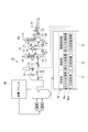
- a CO 2 recovery device (hereinafter simply referred to as a recovery device) 10 includes, for example, an exhaust gas G1 containing CO 2 and O 2 discharged from a boiler 11 constituting a power plant 40 using fossil fuel.
- the absorption liquid AL is contacted with an absorption tower 13 for removing CO 2 from the exhaust gas G1, a regeneration tower 14 which to release CO 2 from the rich solution RL is absorbent that has absorbed CO 2 to play the absorption liquid AL and As a main component.
- the lean solution RAL which is the regenerated absorbent from which CO 2 has been removed by the regenerator 14, is reused as the absorbent AL by the absorber 13.
- the collection device 10 also includes a collection control unit 30.
- the recovery control unit 30 keeps the CO 2 recovery rate constant even when the load of the power plant 40 located on the upstream side fluctuates and the exhaust gas amount fluctuates, and realizes partial exhaust gas processing. Function.
- the exhaust gas G ⁇ b > 1 containing CO 2 from the boiler 11 is sent to the absorption tower 13 through a flow path F ⁇ b > 1 that connects the boiler 11 and the absorption tower 13.
- a main valve 12 for adjusting the amount of exhaust gas G1 supplied to the absorption tower 13 is provided on the flow path F1.
- the flow path F2 branches from the flow path F1, and the front-end
- the exhaust gas G1 is discharged from the chimney 15 through the flow path F2.
- the branch valve 16 adjusts the discharge amount of the exhaust gas G1 from the chimney 15.
- the exhaust gas flow sensor 24 for measuring the flow rate of all exhaust gas G1 discharged from the boiler 11 (actual exhaust gas flow rate, measurement V G1 ), and the concentration (measurement) of CO 2 contained in the exhaust gas G1
- a CO 2 concentration sensor 25 for measuring Y CO2 is provided.
- information (measurement V G1 , measurement Y CO2 ) measured by the exhaust gas flow rate sensor 24 and the CO 2 concentration sensor 25 is continuously transferred to the recovery control unit 30.
- the actual amount of CO 2 contained in the exhaust gas G1 can be obtained by multiplying the measurement V G1 and the measurement Y CO2 .
- the present invention does not prevent the provision of other elements such as a blower for boosting the exhaust gas, a cooling tower for cooling the exhaust gas G1, and a denitration / desulfurization device between the boiler 11 and the absorption tower 13.
- the exhaust gas G ⁇ b > 1 is in countercurrent contact with an absorbent liquid AL based on an amine solution, for example, and CO 2 in the exhaust gas G ⁇ b > 1 is absorbed by the absorbent liquid AL by a chemical reaction.
- the exhaust gas G2 from which CO 2 has been removed comes into gas-liquid contact with the condensed water containing the absorption liquid AL supplied to the absorption tower 13, and the absorption liquid AL accompanying the exhaust gas G2 is recovered. Released outside.
- the rich solution RL that has absorbed CO 2 is pressurized by the rich solvent pump 17, and is a lean solution that is an absorbent regenerated in the regeneration tower 14 in the rich / lean solvent heat exchanger 19 via the rich solvent valve 18.
- the absorption tower 13 and the regeneration tower 14 are connected by a flow path F3.
- a rich solvent pump 17, a rich solvent valve 18, and a rich / lean solvent heat exchanger 19 are provided in the flow path F3 in this order from the absorption tower 13 side. It has been.
- the rich solution RL that has absorbed CO 2 is supplied to the regeneration tower 14 through the flow path F3.
- the rich solution RL released from the top of the regeneration tower 14 generates an endothermic reaction and releases most of CO 2 .
- the absorbing solution from which a part or most of CO 2 has been released in the regeneration tower 14 is referred to as a semi-lean solution RAL.
- the semi-lean solution RAL becomes an absorbing solution from which almost all of the CO 2 has been removed, that is, the lean solution RAL when reaching the lower portion of the regeneration tower 14.
- the lean solution RAL is superheated by the steam S in the regeneration superheater 22 and supplied to the inside of the regeneration tower 14 as steam. For example, the steam S supplied to the regenerative superheater 22 is circulated with the power plant 40.
- the supply amount of the steam S supplied to the regeneration superheater 22 is controlled by a steam valve 23 provided on the flow path F5.
- CO 2 gas (CO 2 ) accompanied by water vapor released from the rich solution RL and the semi-lean solution RAL is led out from the top of the regeneration tower 14.
- water vapor is condensed by a condenser and water is separated by a separation drum, and then the CO 2 gas is discharged out of the system and collected separately.
- the recovered CO 2 gas is injected into an oil field or stored in an aquifer based on an enhanced oil recovery (EOR) method to prevent global warming.
- EOR enhanced oil recovery
- the regenerated absorbent (lean solution RAL) is pumped by the lean solvent pump 20 and sent to the rich / lean solvent heat exchanger 19 via the lean solvent valve 21.
- the lean solution RAL is cooled by the rich solution RL in the rich / lean solvent heat exchanger 19 and then supplied to the absorption tower 13.
- the regeneration tower 14 and the absorption tower 13 are connected by a flow path F4.
- a lean solvent pump 20, a lean solvent valve 21, and a rich / lean solvent heat exchanger 19 are provided in the flow path F4 in this order from the regeneration tower 14 side. Is provided.
- the lean solution RAL is returned to the absorption tower 13 through the flow path F4.
- the recovery apparatus 10 continuously recovers CO 2 from the exhaust gas G1 discharged from the boiler 11.
- the recovery control unit 30 controls the amount of exhaust gas G1 (exhaust gas treatment rate) to be processed by the recovery device 10 by adjusting the opening degree of the main valve 12 and the branch valve 16. Further, the recovery control unit 30 adjusts the operation and opening of the rich solvent pump 17, rich solvent valve 18, lean solvent pump 20, lean solvent valve 21, and steam valve 23, so that the absorption tower 13 and the regeneration tower 14 controlling the amount of the recovered CO 2 (CO 2 recovery amount).
- Each of the first to fifth embodiments described below is characterized by the contents of this control. However, in either case, even if the exhaust gas flow rate fluctuates as the load of the power plant 40 upstream of the recovery device 10 fluctuates, the exhaust gas recovery rate is made to follow constant, and the exhaust gas is partially exhausted. It is common in that it can be achieved.
- the configuration of the power plant 40 is arbitrary, a high-pressure turbine that guides and drives steam generated in the boiler 11, and a medium-pressure turbine that guides and drives reheat steam that has been returned from the high-pressure turbine and heated again in the boiler 11, and A low-pressure turbine that generates power by an intermediate-pressure turbine and guides and drives the reduced-pressure steam, and a condenser that generates power by the low-pressure turbine and condenses the reduced-pressure steam.
- the collection control unit 30 includes a setting unit 31 that sets operation parameters and others, a calculation unit 32, and a drive control unit 33. See also FIG. 2 below.
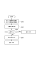
- the setting unit 31 receives and sets the exhaust gas treatment rate R G1 and the CO 2 recovery rate R CO2 as operation parameters (steps S101 and 103 in FIG. 2).
- the exhaust gas treatment rate R G1 is a set value obtained by the following equation, where V G1 is the flow rate of the exhaust gas G1 discharged from the boiler 11 and T CO2 is the amount of the exhaust gas G1 processed by the recovery device 10.
- R G1 T CO2 / V G1
- the recovery control unit 30 continuously acquires information related to the actual flow rate (measurement V G1 ) of the exhaust gas G1 discharged from the boiler 11 from the exhaust gas flow rate sensor 24 (step S105 in FIG. 2). Further, the recovery control unit 30 continuously obtains information on the CO 2 concentration (measurement Y CO2 ) contained in the exhaust gas G1 discharged from the boiler 11 from the CO 2 concentration sensor 25 ((FIG. 2 step) S109)).
- the recovery controller 30 multiplies the measurement V G1 acquired from the exhaust gas flow rate sensor 24 by the exhaust gas flow rate sensor 24 and the exhaust gas treatment rate R G1 set as a parameter, and targets the exhaust gas G1 to be processed by the CO 2 recovery device 10.
- the flow rate is set (FIG. 2, step S107). Based on this set value, the drive control unit 33 controls the opening degree of the main valve 12 and the branch valve 16 (flow rate controller) (step S113 in FIG. 2).
- the main valve 12 is fully opened while the branch valve 16 is fully closed in order to process the entire amount of the measurement V G1 with the recovery device 10. To do. By doing so, even if the load of the power plant 40 fluctuates and the flow rate of the exhaust gas G1 discharged from the boiler 11 changes, all of the exhaust gas G1 is supplied to the absorption tower 13 through the flow path F1. .
- the exhaust gas treatment rate R G1 is set to 50%
- 50% of the measurement V G1 is processed by the recovery device 10 and the remaining 50% is discharged outside the system via the chimney 15. Is done. Therefore, for example, the opening degree of the main valve 12 is set to 50%, while the opening degree of the branch valve 16 is set to 50%.
- the exhaust gas treatment rate R G1 and the CO 2 recovery rate RCO 2 are multiplied by 4 to obtain a target value of the amount of CO 2 to be processed and recovered by the recovery device 10 (step S111 in FIG. 2).
- the calculation unit 32 calculates an absorption liquid circulation flow rate and a steam supply flow rate, which are operation parameters of the recovery device 10.
- the absorption liquid circulation flow rate is controlled by adjusting the rich solvent pump 17, the rich solvent valve 18, the lean solvent pump 20 and the lean solvent valve 21, and the steam supply flow rate is adjusted by adjusting the water vapor valve 23.
- the drive control unit 33 determines the discharge amount of the rich solvent pump 17, the lean solvent pump 20, the rich solvent valve 18, the lean solvent valve 21 and the like based on the absorption liquid circulation flow rate and the steam supply flow rate calculated by the calculation unit 32.
- the amount of CO 2 to be recovered is controlled by adjusting the opening of the water vapor valve 23 (step S115 in FIG. 2).
- the above control procedure is continuously executed until there is an operation stop command for the power plant 40 (step S116 in FIG. 2).
- the CO 2 recovery rate is kept constant. And exhaust gas can be partially treated.
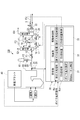
- the CO 2 recovery device 110 of the second embodiment is obtained by calculation without measuring the flow rate (measurement V G1 ) of the exhaust gas G1 discharged from the boiler 11 and the concentration of CO 2 contained therein (measurement Y CO2 ). Except for this point, the second embodiment is the same as the first embodiment. Therefore, below, it demonstrates centering around difference with 1st Embodiment.
- 2nd Embodiment measures the combustion air flow volume (measurement Va) supplied to the boiler 11, and the fuel flow volume (measurement Vf) instead of measurement V G1 , and these total values (measurement) are shown in FIG. Vf + measurement Va) is used as an alternative value for measurement V G1 (actual flow rate of exhaust gas G1) of the first embodiment.
- set values setting Va and setting Vf can be used as an alternative to the measurement Va and measurement Vf.
- the CO 2 concentration is obtained by calculating the gas composition after combustion, and the first embodiment It is used as an alternative value for the measurement YCO2 in the embodiment.
- the flow rate of the exhaust gas G1 can be directly obtained by measurement as in the first embodiment, and the combustion air flow rate (measurement Va, setting Va) and the fuel flow rate (measurement) as in the second embodiment.
- Vf, setting Vf) can be obtained indirectly by calculation.
- the CO 2 concentration can be obtained directly by measurement as in the first embodiment, or can be obtained by calculation based on the composition of air and fuel supplied as in the second embodiment. Since the exhaust gas actual flow rate and CO 2 concentration obtained by calculation have sufficient accuracy as an alternative to the exhaust gas flow rate and CO 2 concentration obtained by measurement, the second embodiment also differs from the first embodiment. Similar effects can be obtained.
- the actual flow rate of the exhaust gas G1 from the boiler 11 that is generally difficult to measure accurately can be obtained from the air flow rate and the fuel flow rate that are relatively easy to measure in the second embodiment.
- the composition can be determined relatively easily by calculation.
- the recovery device 120 of the third embodiment is intended to improve followability when the load on the boiler 11 that is the upstream equipment fluctuates greatly.
- the third embodiment uses the target value of power generation output control in the power plant 40 as a load command signal, and prepares table data in which this load command signal is associated with the CO 2 amount V CO2 contained in the exhaust gas G1. To do.
- This table data is stored in the setting unit 31 of the collection control unit 30 as shown in FIG. This table data is given as, for example, the following function.
- V CO2 FA (L SIG ) L SIG : Load command signal
- the collection control unit 30 acquires the load command signal L SIG from the power plant 40.
- CO 2 target recovery amount FA (L SIG ) ⁇ exhaust gas treatment rate R G1 ⁇ CO 2 recovery rate R CO2
- the recovery device 120 uses the above estimated value as the amount of CO 2 to be recovered while the load on the boiler 11 fluctuates greatly. Otherwise, the first embodiment (second embodiment). Should be applied. Therefore, the collection device 120 employs the following procedure. As shown in FIGS. 4 and 5, the recovery control unit 30 acquires the load set value B1 of the boiler 11 and also acquires the load measurement value B2 of the boiler 11 (step S201 in FIG. 5). In addition, the load measurement value of the boiler 11 can be calculated
- the collection control unit 30 further obtains a difference ⁇ MW1 (absolute value) between the load setting value B1 and the load measurement value B2, and compares the difference ⁇ MW1 with a predetermined value x (step S203 in FIG. 5). If the difference ⁇ MW1 between the load setting value B1 and the load measurement value B2 is large, it is determined that the load on the boiler 11 has fluctuated greatly. If the difference is less than the predetermined value x, the process proceeds to step S101 in FIG. 2, and the operation of the collection apparatus 10 is performed in the same procedure as in the first embodiment.
- ⁇ MW1 absolute value
- the recovery control unit 30 determines the amount of CO 2 in the exhaust gas G1 from the table data (FA (L SIG )) based on the acquired load command signal (step S205 in FIG. 5). V CO2 is specified (step S207 in FIG. 5). Thereafter, the process proceeds to step S101 in FIG. 2, and the recovery apparatus 120 is operated in the same procedure as in the first embodiment. However, table data (FA (L SIG )) is used instead of the CO 2 target recovery amount calculation (step S111 in FIG. 2).
- the recovery device 10 according to the third embodiment has the same effect as that of the first embodiment, and can set the CO 2 target recovery amount in advance, so that it can cope with the load fluctuation of the boiler 11.
- followability is improved.
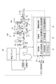
- the recovery apparatus 10 uses a part of steam generated by the power plant 40, more specifically, the boiler 11, as a supply destination of steam necessary for the regeneration tower 14. Therefore, when the amount of steam supplied to the regeneration tower 14 increases, there is a risk that the power generation capacity of the power plant 40 is impaired by that amount. Therefore, in the fourth embodiment, when necessary, the upper limit value of the CO 2 recovery amount that can be recovered by the recovery device 130 is determined, that is, the load of the recovery device 130 is limited, thereby ensuring the power generation capability of the power plant 40. .
- the recovery control unit 30 acquires a target value for power generation output control as a load command signal B SIG for the boiler 11 as shown in FIG. 6. Further, the collection control unit 30 holds the maximum load B max of the boiler 11. For example, if the value of the power generation output is close to the maximum load B max of the boiler 11, it can be said that the remaining power that can be divided from the load of the boiler 11 to the recovery device 130 is small. Therefore, the recovery control unit 30 determines a difference ⁇ MW2 between the maximum load B max of the boiler 11 and the load command signal B SIG in order to determine the remaining capacity of the boiler 11. The larger the difference is, the larger the remaining capacity of the boiler 11 is.
- the recovery device 130 obtains the process-recoverable amount of CO 2 in accordance with this difference.
- the collection control unit 30 stores in the setting unit 31 table data in which the difference is associated with the amount of CO 2 that can be collected.
- This table data is given as, for example, the following function.
- CO 2 max FB ( ⁇ MW2)
- the collection control unit 30 sets the obtained CO 2 amount to the collected amount upper limit CO 2 max by referring to the table data while sequentially obtaining the difference ⁇ MW2. As CO 2 recovery amount obtained in the first embodiment or the second embodiment does not exceed the recovery amount upper limit CO 2 max, recovery controller 30 of the fourth embodiment a limit.
- the collection control unit 30 of the fourth embodiment operates the collection apparatus 10 in the procedure shown in FIG.
- the recovery control unit 30 obtains the load command signal B SIG from the power plant 40 and obtains a difference ⁇ MW2 from the maximum load B max of the boiler 11 held by itself (steps S301 and S303 in FIG. 7).
- the collection control unit 30 specifies CO 2 max corresponding to the difference ⁇ MW2 obtained by referring to the table data (step S305 in FIG. 7).
- the recovery control unit 30 compares the target value C CO2 with the recovery amount upper limit value CO 2 max (step S307 in FIG. 7). If the target value C CO2 is less than the upper limit value CO 2 max (Fig.
- step S307 Yes it is determined that there is a margin in the boiler 11, controls the absorption liquid circulation rate and the steam supply flow rate based on the target value C CO2 (FIG. 7 Step S309). If the target value C CO2 upper limit CO 2 max or more (FIG. 7 step S307 No), the absorbing solution on the basis of the upper limit CO 2 max without judges there is no available capacity in the boiler 11, to adopt a target value C CO2 The circulation flow rate and the steam supply flow rate are controlled (step S311 in FIG. 7).
- the same effect as that of the first embodiment is provided, and when the power generation output is to be prioritized, the set value of the CO 2 target recovery amount can be automatically lowered. . Further, even when the exhaust gas treatment rate is erroneously set to a high value, the power plant 40 can be operated without reducing the power generation output.
- the absorption liquid circulation flow set value CL is multiplied by the exhaust gas treatment rate and the CO 2 recovery rate.
- the absorption liquid circulation flow rate is controlled by adjusting the rich solvent pump 17, the rich solvent valve 18, and the like. Any method of the first to third embodiments may be used for the calculation of the CO 2 target recovery amount.
- the boiler 11 has the same effect as the first embodiment, and even if the flow rate of the exhaust gas G1 fluctuates abruptly, by changing the absorption liquid circulation amount following the flow rate variation, the boiler 11 The followability with respect to the load fluctuation is improved. At this time, the CO 2 recovery rate in the absorption tower 13 does not decrease.
- G1 G2 exhaust gas 10, 110, 120, 130, 140 CO 2 recovery device 11 boiler 12 main valve 13 absorption tower 14 regeneration tower 15 chimney 16 branch valve 17 rich solvent pump 18 rich solvent valve 19 rich / lean solvent heat exchanger 20 Lean solvent pump 21 Lean solvent valve 22 Regenerative superheater 23 Steam valve 24 Exhaust gas flow sensor 25 CO 2 concentration sensor 30 Recovery control unit 31 Parameter setting unit 32 Calculation unit 33 Drive control unit 40 Power plant
Landscapes
- Engineering & Computer Science (AREA)
- Chemical & Material Sciences (AREA)
- Oil, Petroleum & Natural Gas (AREA)
- Analytical Chemistry (AREA)
- General Chemical & Material Sciences (AREA)
- Chemical Kinetics & Catalysis (AREA)
- Environmental & Geological Engineering (AREA)
- Health & Medical Sciences (AREA)
- Biomedical Technology (AREA)
- General Engineering & Computer Science (AREA)
- Mechanical Engineering (AREA)
- Combustion & Propulsion (AREA)
- Treating Waste Gases (AREA)
- Gas Separation By Absorption (AREA)
- Carbon And Carbon Compounds (AREA)
Abstract
排ガスの発生源からCO2回収装置に向けて排出される排ガスの実流量と排ガス処理率RG1の積に基づいて処理する排ガスの目標処理量を特定し、かつ、排ガスの発生源から排出される前記排ガスに含まれるCO2の実量と、排ガス処理率RG1と、CO2回収率RCO2と、の積に基づいて前記回収装置で回収するCO2の目標回収量を特定する。 RG1=TCO2/VG1 VG1:排ガスの発生源から排出される排ガスの流量 TCO2:回収装置で処理する排ガスの量 RCO2=CCO2/VCO2 VCO2:回収装置で処理する排ガスに含まれるCO2の量 CCO2:回収装置で回収するCO2の量
Description
本発明は、上流側に位置する装置の負荷の変動に伴う排ガス量の変動に対して回収率を追従させることのできるCO2回収装置に関する。
近年、地球の温暖化現象の原因の一つとして、二酸化炭素(以下、CO2)が指摘されている。そこで、例えば大量の化石燃料を使用する火力発電所などの動力発生設備を対象に、ボイラの燃焼排ガスを吸収液と接触させ、燃焼排ガス中のCO2を除去、回収する方法及び回収されたCO2を大気へ放出することなく貯蔵する方法が精力的に研究されている。
CO2回収装置は、ガス中のCO2を吸収液に吸収させる吸収塔と、吸収液からCO2を分離する再生塔と、を基本的な構成要素として備えている。これまで、CO2回収装置を適正に運転するために、以下に示すようないくつかの提案がなされている。
目標のCO2回収量と排ガス中のCO2濃度から、目標達成に必要な排ガス量を決定し、CO2回収装置へ排ガスを供給する(例えば,特許文献1)。
排ガス源(CO2回収装置の上流に設置されるボイラやガスタービン)からの排ガス量と排ガス中のCO2濃度を計測し、目標CO2回収率達成に必要な運転パラメータを決定する(例えば,特許文献2)。
排ガス源からのガスで、CO2回収装置で処理されず、煙突を通じて大気放出されるガス流量またはガス組成を計測し、大気から煙突へ流入するような流れが生じないように、CO2回収装置へ供給する排ガス量を決定する(例えば,特許文献3)
ところが、特許文献1では、目標CO2回収量を回収するために必要な排ガス流量を算出し、排ガスをCO2回収装置に送り込んでいる。そのために、発電所のように負荷が変動するプラントで、一定率の排ガスを処理する場合には,目標CO2回収量も変動するのにあわせて、その都度目標値を設定する必要が生じてしまう。
また、CO2排出量削減とコストを両立するために、排ガスの一部を処理してCO2を回収(部分処理)できることがCO2装置に望まれている。しかし、特許文献2、3の提案は、排ガス全てをCO2回収装置に引きこむ場合の排ガス量を制御する方法を示しているだけであり、当該提案は排ガスの一部を処理する部分的な排ガスの処理に対応することができない。
本発明は、このような技術的課題に基づいてなされたもので、上流側の負荷が変動し、排ガス量が変動しても、CO2の回収率を一定に追従させることができるとともに、部分的に排ガスを処理することができるCO2回収装置を提供することを目的とする。
また、CO2排出量削減とコストを両立するために、排ガスの一部を処理してCO2を回収(部分処理)できることがCO2装置に望まれている。しかし、特許文献2、3の提案は、排ガス全てをCO2回収装置に引きこむ場合の排ガス量を制御する方法を示しているだけであり、当該提案は排ガスの一部を処理する部分的な排ガスの処理に対応することができない。
本発明は、このような技術的課題に基づいてなされたもので、上流側の負荷が変動し、排ガス量が変動しても、CO2の回収率を一定に追従させることができるとともに、部分的に排ガスを処理することができるCO2回収装置を提供することを目的とする。
本発明のCO2回収装置は、CO2を含有する排ガスと吸収液とを接触させて排ガス中のCO2を除去するCO2吸収塔と、CO2吸収塔でCO2を吸収したリッチ溶液中のCO2を除去し、再生する再生塔と、を備え、再生塔でCO2を除去したリーン溶液である吸収液をCO2吸収塔で再利用するものである。
本発明のCO2回収装置は下記に示す排ガス処理率RG1、CO2回収率RCO2をCO2回収装置の運転パラメータとして設定する。
そして、排ガスの発生源からCO2回収装置に向けて排出される排ガスの実流量と排ガス処理率RG1の積に基づいてCO2回収装置で処理する排ガスの目標処理量を特定する。
また、排ガスの発生源からCO2回収装置に向けて排出される排ガスに含まれるCO2の実量と、排ガス処理率RG1と、CO2回収率RCO2と、の積に基づいてCO2回収装置で回収するCO2の目標回収量を特定する。
RG1=TCO2/VG1
VG1:排ガスの発生源から排出される排ガスの流量
TCO2:CO2回収装置で処理する排ガスの量
RCO2=CCO2/VCO2
VCO2:CO2回収装置で処理する排ガスに含まれるCO2の量
CCO2:CO2回収装置で回収するCO2の量
本発明のCO2回収装置において、排ガスの実流量及び排ガスに含まれるCO2の実量は、当該排ガスを計測することにより直接的に求めることができる。また、排ガスの実流量は、排ガスの発生源に供給される燃料の流量及び燃焼ガスの流量に基づいて、また、排ガスに含まれるCO2の実量は、前記燃料及び前記燃焼ガスの流量および組成に基づいて、計算により間接的に求めることもできる。
本発明のCO2回収装置において、排ガスの発生源の負荷が所定値以上に変動すると、排ガスの発生源への負荷と排ガスの流量とが対応付けられたデータと、排ガスの発生源への負荷指令信号と、を照合することにより排ガスの実流量を求め、CO2の目標回収量を特定することが好ましい。
そうすることで、負荷変動に対する追従性が向上する。
そうすることで、負荷変動に対する追従性が向上する。
本発明のCO2回収装置において、排ガスの発生源の負荷に基づいて、CO2の回収量に上限を設定することができる。
CO2回収装置の動力源に、例えば上流側のプラントで消費される蒸気を用いる場合に、CO2回収装置で消費される蒸気量が多くなりすぎると、その分だけ上流側のプラントで消費できる量が不足するおそれがある。そこで、CO2回収装置におけるCO2回収量に上限を設けることで、CO2回収装置で消費される蒸気量を制限する。
CO2回収装置の動力源に、例えば上流側のプラントで消費される蒸気を用いる場合に、CO2回収装置で消費される蒸気量が多くなりすぎると、その分だけ上流側のプラントで消費できる量が不足するおそれがある。そこで、CO2回収装置におけるCO2回収量に上限を設けることで、CO2回収装置で消費される蒸気量を制限する。
本発明のCO2回収装置において、排ガスの発生源の負荷に基づいて、吸収液循環流量の目標値を設定することができる。
そうすることで、排ガス流量が急激に変動した場合でも,この流量に追従して吸収液循環流量を変動させることで,負荷追従性を向上できる。
そうすることで、排ガス流量が急激に変動した場合でも,この流量に追従して吸収液循環流量を変動させることで,負荷追従性を向上できる。
本発明によれば、上流側の負荷が変動し、排ガス量が変動した場合でも、回収率を一定に追従させることができるとともに、部分的に排ガスを処理することができるCO2回収装置が提供される。
[CO2回収装置の基本構成]
以下、本発明のいくつかの実施形態を説明するが、いずれの実施形態も適用されるCO2回収装置の基本的な構成は同じである。そこで、はじめにそのCO2回収装置について説明する。
図1に示すように、CO2回収装置(以下、単に回収装置)10は、例えば化石燃料を用いる発電プラント40を構成するボイラ11から排出されたCO2とO2とを含有する排ガスG1と吸収液ALとを接触させて排ガスG1からCO2を除去する吸収塔13と、CO2を吸収した吸収液であるリッチ溶液RLからCO2を放出させて吸収液ALを再生する再生塔14とを主構成要素として備えている。
そして、この回収装置10では、再生塔14でCO2を除去した再生吸収液であるリーン溶液RALは吸収塔13で吸収液ALとして再利用する。
回収装置10は、また、回収制御部30を備える。回収制御部30は、上流側に位置する発電プラント40の負荷が変動し、排ガス量が変動した場合でもCO2の回収率を一定に追従させるとともに、部分的な排ガスの処理を実現するために機能する。
回収装置10において、ボイラ11からのCO2を含んだ排ガスG1がボイラ11と吸収塔13を繋ぐ流路F1を通じて吸収塔13に送られる。この流路F1上には、排ガスG1が吸収塔13に供給される量を調整する主バルブ12が設けられている。
流路F1から流路F2が分岐しており、分岐バルブ16が設けられた流路F2の先端は煙突15に繋がれている。ボイラ11から排出される排ガスG1の中の一部を吸収塔13に送らずに系外に排出する際に、流路F2を介して煙突15から排ガスG1が排出される。分岐バルブ16は、煙突15からの排ガスG1の排出量を調整する。
流路F1上には、ボイラ11から排出されるすべての排ガスG1の流量(実排ガス流量,計測VG1)を計測する排ガス流量センサ24、及び、その排ガスG1に含まれるCO2の濃度(計測YCO2)を計測するCO2濃度センサ25を備えている。発電プラント40、ボイラ11の運転中、排ガス流量センサ24及びCO2濃度センサ25で計測された情報(計測VG1、計測YCO2)は回収制御部30に継続的に転送される。排ガスG1に含まれるCO2の実量は、計測VG1と計測YCO2とを乗ずることにより求めることができる。
なお、ボイラ11と吸収塔13の間に、排ガスを昇圧させる送風機、排ガスG1を冷却する冷却塔、脱硝・脱硫装置など他の要素を設けることを本発明は妨げない。
吸収塔13において、排ガスG1は例えばアミン系溶液をベースとする吸収液ALと向流接触し、排ガスG1中のCO2は、化学反応により吸収液ALに吸収される。一方で、CO2が除去された後の排ガスG2は、吸収塔13に供給される吸収液ALを含む凝縮水と気液接触して、排ガスG2に同伴する吸収液ALが回収され、その後系外に放出される。
また、CO2を吸収したリッチ溶液RLは、リッチソルベントポンプ17により昇圧され、リッチソルベントバルブ18を介してリッチ/リーンソルベント熱交換器19において、再生塔14で再生された吸収液であるリーン溶液RALにより加熱され、再生塔14に供給される。吸収塔13と再生塔14は、流路F3で繋がれており、流路F3には吸収塔13側から順に、リッチソルベントポンプ17、リッチソルベントバルブ18及びリッチ/リーンソルベント熱交換器19が設けられている。CO2を吸収したリッチ溶液RLは、この流路F3を通って再生塔14に供給される。
また、CO2を吸収したリッチ溶液RLは、リッチソルベントポンプ17により昇圧され、リッチソルベントバルブ18を介してリッチ/リーンソルベント熱交換器19において、再生塔14で再生された吸収液であるリーン溶液RALにより加熱され、再生塔14に供給される。吸収塔13と再生塔14は、流路F3で繋がれており、流路F3には吸収塔13側から順に、リッチソルベントポンプ17、リッチソルベントバルブ18及びリッチ/リーンソルベント熱交換器19が設けられている。CO2を吸収したリッチ溶液RLは、この流路F3を通って再生塔14に供給される。
再生塔14の上部から内部に放出されたリッチ溶液RLは、吸熱反応を生じて、大部分のCO2を放出する。再生塔14内で一部または大部分のCO2を放出した吸収液はセミリーン溶液RALと称される。このセミリーン溶液RALは、再生塔14の下部に至る頃には、ほぼ全てのCO2が除去された吸収液、つまりリーン溶液RALとなる。リーン溶液RALは再生過熱器22で水蒸気Sにより過熱され、再生塔14の内部に蒸気として供給される。再生過熱器22に供給される水蒸気Sは、例えば発電プラント40との間で循環させる。そして、再生過熱器22に供給される水蒸気Sは、流路F5上に設けられた水蒸気バルブ23により供給量が制御される。
一方、再生塔14の頭頂部からは塔内においてリッチ溶液RLおよびセミリーン溶液RALから放出された水蒸気を伴ったCO2ガス(CO2)が導出される。このCO2ガスは、例えばコンデンサにより水蒸気が凝縮され、分離ドラムにて水を分離した後に、系外に放出されて別途回収される。この回収されたCO2ガスは、石油増進回収法(EOR:Enhanced Oil Recovery)に基づいて油田中に圧入するか、帯水層へ貯留し、温暖化対策を図っている。なお、分離された水は再生塔14の上部に供給される。
再生された吸収液(リーン溶液RAL)は、リーンソルベントポンプ20により圧送され、リーンソルベントバルブ21を介してリッチ/リーンソルベント熱交換器19に向けて送られる。そして、リーン溶液RALはリッチ/リーンソルベント熱交換器19においてリッチ溶液RLにより冷却された後に、吸収塔13に供給される。再生塔14と吸収塔13とは、流路F4で繋がれており、流路F4には再生塔14側から順に、リーンソルベントポンプ20、リーンソルベントバルブ21及びリッチ/リーンソルベント熱交換器19が設けられている。リーン溶液RALは、この流路F4を通って吸収塔13に戻される。
以上の一連のサイクルを繰り返すことで、回収装置10は、ボイラ11から排出される排ガスG1からCO2を連続的に回収する。その過程で、回収制御部30は、主バルブ12、分岐バルブ16の開度を調整することで、回収装置10で処理する排ガスG1の量(排ガス処理率)を制御する。また、回収制御部30は、リッチソルベントポンプ17、リッチソルベントバルブ18、リーンソルベントポンプ20、リーンソルベントバルブ21、水蒸気バルブ23の運転、開度を調整することで、吸収塔13、再生塔14により回収されるCO2の量(CO2回収量)を制御する。以下説明する第1実施形態~第5実施形態の各々は、この制御の内容に特徴を有している。ただし、いずれも、回収装置10よりも上流側の発電プラント40の負荷が変動するのにともなって排ガス流量が変動しても、排ガス回収率を一定に追従させること、及び、部分的に排ガスを処理すること、を達成できる点で共通する。
発電プラント40の構成は任意であり、ボイラ11で発生した蒸気を導いて駆動する高圧タービンと、高圧タービンから戻されてボイラ11で再度加熱された再熱蒸気を導いて駆動する中圧タービンと、中圧タービンで動力を発生して減圧された蒸気を導いて駆動する低圧タービンと、低圧タービンで動力を発生して減圧された蒸気を復水する復水器と、を備えることができる。
〔第1実施形態〕
第1実施形態による回収制御部30は、図1に示すように、運転パラメータ、その他を設定する設定部31と、演算部32と、駆動制御部33と、を備えている。以下、図2も参照されたい。
設定部31には、運転パラメータとして、排ガス処理率RG1とCO2回収率RCO2が入力、設定される(図2 ステップS101,103)。
排ガス処理率RG1は、ボイラ11から排出される排ガスG1の流量をVG1とし、回収装置10で処理する排ガスG1の量をTCO2とすると、以下の式により求められる設定値である。
RG1=TCO2/VG1
また、CO2回収率RCO2は、回収装置10で処理する排ガスG1に含まれるCO2の量をVCO2、回収するCO2の量をCCO2とすると、以下の式により求められる設定値である。
RCO2=CCO2/VCO2
回収制御部30は、排ガス流量センサ24から、ボイラ11から排出される排ガスG1の実流量(計測VG1)に関する情報を継続して取得している(図2 ステップS105)。また、回収制御部30は、CO2濃度センサ25から、ボイラ11から排出される排ガスG1に含まれるCO2の濃度(計測YCO2)に関する情報を継続して取得している((図2 ステップS109))。
回収制御部30は、演算部32が、排ガス流量センサ24から取得した計測VG1と、パラメータとして設定されている排ガス処理率RG1とを乗じ、CO2回収装置10で処理する排ガスG1の目標流量を設定する(図2 ステップS107)。この設定値に基づいて、駆動制御部33が主バルブ12及び分岐バルブ16(流量制御器)の開度を制御する(図2 ステップS113)。
例えば、排ガス処理率RG1が100%と設定されている場合には、計測VG1の全量を回収装置10で処理するために、主バルブ12を全開にする一方、分岐バルブ16を全閉にする。そうすることで、発電プラント40の負荷が変動してボイラ11から排出される排ガスG1の流量が変動しても、排ガスG1は、そのすべてが流路F1を通って吸収塔13に供給される。
また、例えば排ガス処理率RG1が50%と設定されている場合には、計測VG1の50%の量を回収装置10で処理し、残りの50%が煙突15を介して系外に排出される。そのために、例えば、主バルブ12の開度を50%にする一方、分岐バルブ16の開度を50%にする。そうすることで、発電プラント40の負荷が変動してボイラ11から排出される排ガスG1の流量が変動しても、排ガスG1の50%だけが流路F1を通って吸収塔13に供給されるので、設定された排ガス処理率RG1を維持しつつ部分的な排ガスの処理を実現する。
また、例えば排ガス処理率RG1が50%と設定されている場合には、計測VG1の50%の量を回収装置10で処理し、残りの50%が煙突15を介して系外に排出される。そのために、例えば、主バルブ12の開度を50%にする一方、分岐バルブ16の開度を50%にする。そうすることで、発電プラント40の負荷が変動してボイラ11から排出される排ガスG1の流量が変動しても、排ガスG1の50%だけが流路F1を通って吸収塔13に供給されるので、設定された排ガス処理率RG1を維持しつつ部分的な排ガスの処理を実現する。
また、回収制御部30は、演算部32が、CO2濃度センサ25から取得した計測YCO2(排ガス中のCO2濃度)と、排ガス流量センサ24から取得した計測VG1と、パラメータとして設定されている排ガス処理率RG1及びCO2回収率RCO2の4つを乗じ、回収装置10で処理・回収するCO2量の目標値とする(図2 ステップS111)。さらにこの設定値に基づいて、演算部32は、回収装置10の運転パラメータである吸収液循環流量及び蒸気供給流量を算出する。ここで、吸収液循環流量は、リッチソルベントポンプ17、リッチソルベントバルブ18、リーンソルベントポンプ20及びリーンソルベントバルブ21を調整することにより制御し、また、蒸気供給流量は水蒸気バルブ23を調整することにより制御できる。したがって、駆動制御部33は、演算部32で算出された吸収液循環流量及び蒸気供給流量に基づいて、リッチソルベントポンプ17、リーンソルベントポンプ20の吐出量、リッチソルベントバルブ18、リーンソルベントバルブ21及び水蒸気バルブ23の開度を調整することで、回収するCO2量を制御する(図2 ステップS115)。
以上の制御手順は、発電プラント40の運転停止指令があるまで継続して実行される(図2 ステップS116)。
以上の制御手順は、発電プラント40の運転停止指令があるまで継続して実行される(図2 ステップS116)。
以上説明したように、第1実施形態によると、回収装置10よりも上流側の装置であるボイラ11の負荷が変動し、排ガスG1の流量が変動しても、CO2回収率を一定に追従させることができるとともに、部分的に排ガスを処理することができる。
〔第2実施形態〕
第2実施形態のCO2回収装置110は、ボイラ11から排出される排ガスG1の流量(計測VG1)及びそこに含まれるCO2の濃度(計測YCO2)を計測することなく、計算により求める点を除けば第1実施形態と同様である。したがって、以下では第1実施形態との相違点を中心に説明する。
第2実施形態のCO2回収装置110は、ボイラ11から排出される排ガスG1の流量(計測VG1)及びそこに含まれるCO2の濃度(計測YCO2)を計測することなく、計算により求める点を除けば第1実施形態と同様である。したがって、以下では第1実施形態との相違点を中心に説明する。
第2実施形態は、計測VG1の代わりに、図3に示すように、ボイラ11に供給される燃焼空気流量(計測Va)及び燃料流量(計測Vf)を計測し、これらの合計値(計測Vf+計測Va)を第1実施形態の計測VG1(排ガスG1の実流量)の代替値として用いる。
または、ボイラ11に供給される燃焼空気及び燃料は、予め設定されているのが通常であるから、計測Va及び計測Vfの代替として設定値(設定Va及び設定Vf)を用いることもできる。
または、ボイラ11に供給される燃焼空気及び燃料は、予め設定されているのが通常であるから、計測Va及び計測Vfの代替として設定値(設定Va及び設定Vf)を用いることもできる。
また、第2実施形態は、図3に示すように、ボイラ11に供給される燃料及び空気の組成が既知の場合は、燃焼後のガス組成を計算することによりCO2濃度を求め、第1実施形態の計測YCO2の代替値として用いる。
以上の通りであり、排ガスG1の流量は、第1実施形態のように計測により直接求めることができるし、第2実施形態のように燃焼空気流量(計測Va,設定Va)及び燃料流量(計測Vf,設定Vf)から計算により間接的に求めることができる。同様に、CO2濃度は、第1実施形態のように計測により直接求めることができるし、第2実施形態のように供給される空気及び燃料の組成に基づいて計算により求めることができる。そして、計算により求められる排ガス実流量、CO2濃度は、計測により求められる排ガス流量、CO2濃度の代替として十分な精度を有しているので、第2実施形態においても、第1実施形態と同様の効果を得ることができる。
加えて、正確に計測することは一般的には難しいボイラ11からの排ガスG1の実流量を、第2実施形態では、計測が比較的容易な空気流量・燃料流量から求めることできる利点がある。これは、ボイラ11からの排ガスG1に含まれるCO2濃度についても同様であり、CO2濃度を連続して計測することが難しくかつ、組成がほぼ一定の燃料及び空気からボイラ11からの排ガスの組成を、計算により比較的容易に求めることができる。
加えて、正確に計測することは一般的には難しいボイラ11からの排ガスG1の実流量を、第2実施形態では、計測が比較的容易な空気流量・燃料流量から求めることできる利点がある。これは、ボイラ11からの排ガスG1に含まれるCO2濃度についても同様であり、CO2濃度を連続して計測することが難しくかつ、組成がほぼ一定の燃料及び空気からボイラ11からの排ガスの組成を、計算により比較的容易に求めることができる。
〔第3実施形態〕
第3実施形態の回収装置120は、上流設備であるボイラ11の負荷が大きく変動した場合の追従性を向上させることを目的としている。そのために、第3実施形態は、発電プラント40における発電出力制御の目標値を負荷指令信号とし、この負荷指令信号と排ガスG1に含まれるCO2の量VCO2が対応付けられたテーブルデータを用意する。このテーブルデータは、図4に示すように、回収制御部30の設定部31に記憶させておく。このテーブルデータは、例えば、以下の関数として与えられる。
VCO2=FA(LSIG) LSIG:負荷指令信号
第3実施形態の回収装置120は、上流設備であるボイラ11の負荷が大きく変動した場合の追従性を向上させることを目的としている。そのために、第3実施形態は、発電プラント40における発電出力制御の目標値を負荷指令信号とし、この負荷指令信号と排ガスG1に含まれるCO2の量VCO2が対応付けられたテーブルデータを用意する。このテーブルデータは、図4に示すように、回収制御部30の設定部31に記憶させておく。このテーブルデータは、例えば、以下の関数として与えられる。
VCO2=FA(LSIG) LSIG:負荷指令信号
回収装置120は、回収制御部30が発電プラント40から負荷指令信号LSIGを取得する。回収制御部30は、負荷指令信号LSIGを取得しながら上記テーブルデータを参照することで、CO2量(VCO2=FA(LSIG)を特定する。そうすると、演算部32は、以下の式に基づいて、CO2目標回収量(推測値)を求める。
CO2目標回収量=FA(LSIG)×排ガス処理率RG1×CO2回収率RCO2
CO2目標回収量=FA(LSIG)×排ガス処理率RG1×CO2回収率RCO2
第3実施形態による回収装置120が、回収するCO2量として以上の推測値を用いるのは、ボイラ11の負荷が大きく変動する間であり、それ以外では第1実施形態(第2実施形態)を適用すればよい。そのために、回収装置120は以下の手順を採用する。
図4、図5に示すように、回収制御部30は、ボイラ11の負荷設定値B1を取得するとともに、ボイラ11の負荷計測値B2を取得する(図5 ステップS201)。なお、ボイラ11の負荷計測値は、燃料流量及び蒸気発生量などから計算により求めることができる。
回収制御部30は、さらに、負荷設定値B1と負荷計測値B2の差分ΔMW1(絶対値)を求めるとともに、この差分ΔMW1と既定値xを比較する(図5 ステップS203)。負荷設定値B1と負荷計測値B2の差分ΔMW1が大きければ、ボイラ11の負荷が大きく変動していると判断する。
差分が既定値x未満であれば、図2のステップS101に進み、以下は第1実施形態と同様の手順で回収装置10の運転が行われる。
一方、差分が既定値x以上であれば、回収制御部30は、取得した負荷指令信号(図5 ステップS205)に基づいて、テーブルデータ(FA(LSIG))より排ガスG1中のCO2量VCO2を特定する(図5 ステップS207)。
以後は、図2のステップS101に進み、第1実施形態と同様の手順で回収装置120の運転が行われる。ただし、CO2目標回収量演算(図2 ステップS111)の代わりにテーブルデータ(FA(LSIG))を用いる。
以上説明のように、第3実施形態による回収装置10は、第1実施形態と同様の効果を備えるとともに、CO2目標回収量を先行的に設定することができるので、ボイラ11の負荷変動に対する追従性が向上する。
〔第4実施形態〕
回収装置10は、再生塔14に必要な蒸気の供給先を発電プラント40、より具体的にはボイラ11で生成した蒸気の一部を用いている。したがって、再生塔14に供給する蒸気の量が多くなると、その分だけ発電プラント40における発電能力を損なう恐れがある。そこで、第4実施形態では、必要な時には回収装置130において回収可能なCO2回収量の上限値を定める、つまり回収装置130の負荷に制限を設けることにより、発電プラント40の発電能力を担保する。
回収装置10は、再生塔14に必要な蒸気の供給先を発電プラント40、より具体的にはボイラ11で生成した蒸気の一部を用いている。したがって、再生塔14に供給する蒸気の量が多くなると、その分だけ発電プラント40における発電能力を損なう恐れがある。そこで、第4実施形態では、必要な時には回収装置130において回収可能なCO2回収量の上限値を定める、つまり回収装置130の負荷に制限を設けることにより、発電プラント40の発電能力を担保する。
そのために、第4実施形態の回収制御部30は、図6に示すように、発電出力制御の目標値をボイラ11の負荷指令信号BSIGとして取得する。また、回収制御部30は、ボイラ11の最大負荷Bmaxを保持する。
例えば、ボイラ11の最大負荷Bmaxに対して発電出力の値が近くなれば、ボイラ11の負荷から回収装置130に割ける余力は小さいといえる。そこで回収制御部30は、ボイラ11の余力を判断するために、ボイラ11の最大負荷Bmaxと負荷指令信号BSIGの差分ΔMW2を求める。この差分が大きいほどボイラ11の余力が大きく、逆に、差分が小さいほどボイラ11の余力は小さくなる。そして、この差分に応じて回収装置130が処理・回収可能なCO2量を求める。そのために、回収制御部30は、当該差分と回収可能なCO2量とが対応付けられたテーブルデータを設定部31に記憶させておく。このテーブルデータは、例えば、以下の関数として与えられる。
CO2max=FB(ΔMW2)
回収制御部30は、差分ΔMW2を逐次求めながら、テーブルデータを参照することで、求められたこのCO2量を回収量上限値CO2maxに設定する。そして、第1実施形態又は第2実施形態で求められるCO2回収量が回収量上限値CO2maxを超えないように、第4実施形態の回収制御部30は制限を設ける。
第4実施形態の回収制御部30は、図7に示す手順で回収装置10を運転する。
回収制御部30は、負荷指令信号BSIGを発電プラント40から取得するとともに、自己が保持しているボイラ11の最大負荷Bmaxとの差分ΔMW2を求める(図7 ステップS301,S303)。
次いで、回収制御部30は、テーブルデータを参照することで求められた差分ΔMW2に対応するCO2maxを特定する(図7 ステップS305)。
次に、回収制御部30は、目標値CCO2と回収量上限値CO2maxの大小を比較する(図7 ステップS307)。目標値CCO2が上限値CO2max未満(図7 ステップS307 Yes)であれば、ボイラ11に余力があると判断し、目標値CCO2に基づいて吸収液循環流量及び蒸気供給流量を制御する(図7 ステップS309)。目標値CCO2が上限値CO2max以上(図7 ステップS307 No)であれば、ボイラ11に余力がない判断し、目標値CCO2を採用することなく上限値CO2maxに基づいて吸収液循環流量及び蒸気供給流量を制御する(図7 ステップS311)。
以上説明したように、第4実施形態によると、第1実施形態と同様の効果を備えるとともに、発電出力を優先させたい場合に、自動的にCO2目標回収量の設定値を下げることができる。また、排ガス処理率を誤って高い値に設定した場合でも、発電出力を低下させることなく発電プラント40を運転できる。
〔第5実施形態〕
第5実施形態の回収装置140は、回収制御部30の設定部31が、ボイラ負荷指令(燃料流量設定値,空気流量設定値)BSIGと吸収液循環流量CLとを対応付けたテーブルデータを保持する。このテーブルデータは以下の関数として与えられる。
CL=FC(BSIG)
回収制御部30は、図8に示すように、ボイラ負荷指令BSIGを取得するとともに、設定部31のテーブルデータ(CL=FC(BSIG))を参照することで、吸収液循環流量設定値CLを特定し、実際の吸収液循環流量が設定値となるように制御する。ただし、吸収液循環流量設定値CLは、排ガス処理率及びCO2回収率を乗じたものとする。吸収液循環流量は、リッチソルベントポンプ17、リッチソルベントバルブ18等を調節することにより制御される。CO2目標回収量の演算は第1実施形態~第3実施形態のいずれの方法を用いてもよい。
第5実施形態によると、第1実施形態と同様の効果を備えるとともに、排ガスG1の流量が急激に変動しても,この流量変動に追従して吸収液循環量を変動させることで、ボイラ11の負荷変動に対する追従性が向上する。このとき、吸収塔13におけるCO2回収率は低下しない。
上記実施形態では、発電プラント40のボイラ11で発生するCO2を回収する例について説明したが、本発明の対象はこれに限らず、CO2を発生するいかなる装置、設備についても適用することができる。
また、吸収液の循環流量を制御する手段として、リッチソルベントポンプ17、リーンソルベントポンプ20等を示したが、これもまた一例であり、吸収液の循環流量を制御できる手段を広く適用することができる。
また、吸収液回収のための蒸気の供給源は発電プラント40に限らず、個別に設けることができる。
これ以外にも、本発明の主旨を逸脱しない限り、上記実施の形態で挙げた構成を取捨選択したり、他の構成に適宜変更することが可能である。
また、吸収液の循環流量を制御する手段として、リッチソルベントポンプ17、リーンソルベントポンプ20等を示したが、これもまた一例であり、吸収液の循環流量を制御できる手段を広く適用することができる。
また、吸収液回収のための蒸気の供給源は発電プラント40に限らず、個別に設けることができる。
これ以外にも、本発明の主旨を逸脱しない限り、上記実施の形態で挙げた構成を取捨選択したり、他の構成に適宜変更することが可能である。
G1,G2 排ガス
10,110,120,130,140 CO2回収装置
11 ボイラ
12 主バルブ
13 吸収塔
14 再生塔
15 煙突
16 分岐バルブ
17 リッチソルベントポンプ
18 リッチソルベントバルブ
19 リッチ/リーンソルベント熱交換器
20 リーンソルベントポンプ
21 リーンソルベントバルブ
22 再生過熱器
23 水蒸気バルブ
24 排ガス流量センサ
25 CO2濃度センサ
30 回収制御部
31 パラメータ設定部
32 演算部
33 駆動制御部
40 発電プラント
10,110,120,130,140 CO2回収装置
11 ボイラ
12 主バルブ
13 吸収塔
14 再生塔
15 煙突
16 分岐バルブ
17 リッチソルベントポンプ
18 リッチソルベントバルブ
19 リッチ/リーンソルベント熱交換器
20 リーンソルベントポンプ
21 リーンソルベントバルブ
22 再生過熱器
23 水蒸気バルブ
24 排ガス流量センサ
25 CO2濃度センサ
30 回収制御部
31 パラメータ設定部
32 演算部
33 駆動制御部
40 発電プラント
Claims (6)
- CO2を含有する排ガスと吸収液とを接触させて排ガス中のCO2を除去するCO2吸収塔と、
前記CO2吸収塔でCO2を吸収したリッチ溶液中のCO2を除去し、再生する再生塔と、を備え、
前記再生塔でCO2を除去したリーン溶液である吸収液をCO2吸収塔で再利用するCO2回収装置であって、
下記に示す排ガス処理率RG1、CO2回収率RCO2を前記CO2回収装置の運転パラメータとして設定し、
前記排ガスの発生源から前記CO2回収装置に向けて排出される前記排ガスの実流量と前記排ガス処理率RG1の積に基づいて前記CO2回収装置で処理する排ガスの目標処理量を特定し、かつ、
前記排ガスの発生源から前記CO2回収装置に向けて排出される前記排ガスに含まれるCO2の実量と、排ガス処理率RG1と、前記CO2回収率RCO2と、の積に基づいて前記CO2回収装置で回収するCO2の目標回収量を特定する、
ことを特徴とするCO2回収装置。
RG1=TCO2/VG1
VG1:排ガスの発生源から排出される排ガスの流量
TCO2:CO2回収装置で処理する排ガスの量
RCO2=CCO2/VCO2
VCO2:CO2回収装置で処理する排ガスに含まれるCO2の量
CCO2:CO2回収装置で回収するCO2の量 - 前記CO2回収装置に向けて排出される前記排ガスの実流量及び前記排ガスに含まれるCO2の実量は、当該排ガスを計測することにより求められる、
請求項1に記載のCO2回収装置。 - 前記排ガスの実流量は、前記排ガスの発生源に供給される燃料の流量及び燃焼ガスの流量に基づいて計算により求められ、かつ、
前記排ガスに含まれるCO2の実量は、前記燃料及び前記燃焼ガスの流量および組成に基づいて、計算により求められる、
請求項1に記載のCO2回収装置。 - 前記排ガスの発生源の負荷が所定値以上に変動すると、
前記排ガスの発生源への負荷と前記排ガスの流量とが対応付けられたデータと、前記排ガスの発生源への負荷指令信号と、を照合することにより前記排ガスの実流量を求め、前記CO2の回収量を特定する、
請求項1に記載のCO2回収装置。 - 前記排ガスの発生源の負荷に基づいて、前記CO2の回収量の上限値が設定される、
請求項1に記載のCO2回収装置。 - 前記排ガスの発生源の負荷に基づいて、吸収液循環量の目標値が設定される、
請求項1に記載のCO2回収装置。
Priority Applications (2)
| Application Number | Priority Date | Filing Date | Title |
|---|---|---|---|
| US14/347,182 US9186620B2 (en) | 2012-02-03 | 2012-10-30 | CO2 recovery device |
| EP12867698.8A EP2821121B1 (en) | 2012-02-03 | 2012-10-30 | Co2 recovery device |
Applications Claiming Priority (2)
| Application Number | Priority Date | Filing Date | Title |
|---|---|---|---|
| JP2012-021940 | 2012-02-03 | ||
| JP2012021940A JP6216490B2 (ja) | 2012-02-03 | 2012-02-03 | Co2回収装置 |
Publications (1)
| Publication Number | Publication Date |
|---|---|
| WO2013114488A1 true WO2013114488A1 (ja) | 2013-08-08 |
Family
ID=48904578
Family Applications (1)
| Application Number | Title | Priority Date | Filing Date |
|---|---|---|---|
| PCT/JP2012/006940 WO2013114488A1 (ja) | 2012-02-03 | 2012-10-30 | Co2回収装置 |
Country Status (4)
| Country | Link |
|---|---|
| US (1) | US9186620B2 (ja) |
| EP (1) | EP2821121B1 (ja) |
| JP (1) | JP6216490B2 (ja) |
| WO (1) | WO2013114488A1 (ja) |
Cited By (3)
| Publication number | Priority date | Publication date | Assignee | Title |
|---|---|---|---|---|
| WO2015111454A1 (ja) * | 2014-01-24 | 2015-07-30 | 三菱重工業株式会社 | Co2回収装置及びco2回収方法 |
| AU2015203510B2 (en) * | 2014-09-22 | 2016-11-24 | Kabushiki Kaisha Toshiba | Carbon dioxide separation and capture apparatus and method of controlling operation of carbon dioxide separation and capture apparatus |
| EP3150270A4 (en) * | 2014-07-10 | 2017-06-14 | Mitsubishi Heavy Industries, Ltd. | Co2 recovery device and co2 recovery method |
Families Citing this family (11)
| Publication number | Priority date | Publication date | Assignee | Title |
|---|---|---|---|---|
| JP6325376B2 (ja) * | 2014-07-10 | 2018-05-16 | 三菱重工業株式会社 | Co2回収装置及びco2回収方法 |
| JP2016187796A (ja) * | 2015-03-30 | 2016-11-04 | 新日鉄住金エンジニアリング株式会社 | 二酸化炭素製造設備及び二酸化炭素製造方法 |
| JP6297006B2 (ja) * | 2015-03-30 | 2018-03-20 | 新日鉄住金エンジニアリング株式会社 | 二酸化炭素製造設備及び二酸化炭素製造方法 |
| JP6796140B2 (ja) | 2016-10-19 | 2020-12-02 | 三菱重工業株式会社 | 二酸化炭素回収システム、火力発電設備、及び、二酸化炭素回収方法 |
| AU2018308960B2 (en) * | 2018-02-20 | 2020-08-20 | Mitsubishi Heavy Industries, Ltd. | Exhaust gas treatment device and exhaust gas treatment method |
| US11236907B2 (en) | 2018-02-20 | 2022-02-01 | Mitsubishi Heavy Industries Engineering, Ltd. | Exhaust gas treatment device and exhaust gas treatment method |
| JP7013322B2 (ja) * | 2018-05-16 | 2022-01-31 | 株式会社東芝 | 二酸化炭素回収システムおよびその運転方法 |
| JP7251720B2 (ja) * | 2018-06-19 | 2023-04-04 | ヤンマーパワーテクノロジー株式会社 | 二酸化炭素回収システム |
| US10566078B1 (en) | 2018-09-19 | 2020-02-18 | Basf Se | Method of Determination of Operating and/or Dimensioning Parameters of A Gas Treatment Plant |
| US20220051756A1 (en) * | 2018-09-19 | 2022-02-17 | Basf Se | Modelling of operating and/or dimensioning parameters of a gas treatment plant |
| JP2023013309A (ja) * | 2021-07-15 | 2023-01-26 | 三菱重工業株式会社 | Co2回収装置の制御装置、co2回収装置の制御方法、及びプログラム |
Citations (3)
| Publication number | Priority date | Publication date | Assignee | Title |
|---|---|---|---|---|
| JP2010017617A (ja) | 2008-07-08 | 2010-01-28 | Mitsubishi Heavy Ind Ltd | 排ガス中の二酸化炭素回収システム |
| JP2011000528A (ja) | 2009-06-17 | 2011-01-06 | Mitsubishi Heavy Ind Ltd | Co2回収装置及び方法 |
| JP2011000527A (ja) | 2009-06-17 | 2011-01-06 | Mitsubishi Heavy Ind Ltd | Co2回収装置及び方法 |
Family Cites Families (6)
| Publication number | Priority date | Publication date | Assignee | Title |
|---|---|---|---|---|
| GB2100471B (en) * | 1981-05-28 | 1985-03-06 | British Gas Corp | Automatic coi removal system and operation thereof |
| US5085839A (en) * | 1990-01-08 | 1992-02-04 | Lyondell Petrochemical Company | Apparatus for the prevention of acid gas excursions |
| US6066304A (en) * | 1998-08-06 | 2000-05-23 | Delores Pircon | Process for removing sulfur dioxide out of a gas |
| US7247279B2 (en) * | 2000-08-01 | 2007-07-24 | Enviroscrub Technologies Corporation | System for removal of pollutants from a gas stream |
| JP5383338B2 (ja) * | 2009-06-17 | 2014-01-08 | 三菱重工業株式会社 | Co2回収装置及びco2回収方法 |
| US8663363B2 (en) * | 2009-06-17 | 2014-03-04 | Mitsubishi Heavy Industries, Ltd. | CO2 recovering apparatus and method |
-
2012
- 2012-02-03 JP JP2012021940A patent/JP6216490B2/ja active Active
- 2012-10-30 WO PCT/JP2012/006940 patent/WO2013114488A1/ja active Application Filing
- 2012-10-30 EP EP12867698.8A patent/EP2821121B1/en active Active
- 2012-10-30 US US14/347,182 patent/US9186620B2/en active Active
Patent Citations (3)
| Publication number | Priority date | Publication date | Assignee | Title |
|---|---|---|---|---|
| JP2010017617A (ja) | 2008-07-08 | 2010-01-28 | Mitsubishi Heavy Ind Ltd | 排ガス中の二酸化炭素回収システム |
| JP2011000528A (ja) | 2009-06-17 | 2011-01-06 | Mitsubishi Heavy Ind Ltd | Co2回収装置及び方法 |
| JP2011000527A (ja) | 2009-06-17 | 2011-01-06 | Mitsubishi Heavy Ind Ltd | Co2回収装置及び方法 |
Cited By (8)
| Publication number | Priority date | Publication date | Assignee | Title |
|---|---|---|---|---|
| WO2015111454A1 (ja) * | 2014-01-24 | 2015-07-30 | 三菱重工業株式会社 | Co2回収装置及びco2回収方法 |
| JP2015136687A (ja) * | 2014-01-24 | 2015-07-30 | 三菱重工業株式会社 | Co2回収装置及びco2回収方法 |
| US10427093B2 (en) | 2014-01-24 | 2019-10-01 | Mitsubishi Heavy Industries Engineering, Ltd. | CO2 recovery apparatus and CO2 recovery process |
| EP3150270A4 (en) * | 2014-07-10 | 2017-06-14 | Mitsubishi Heavy Industries, Ltd. | Co2 recovery device and co2 recovery method |
| AU2015286248B2 (en) * | 2014-07-10 | 2017-12-21 | Mitsubishi Heavy Industries, Ltd. | CO2 recovery unit and CO2 recovery method |
| US9987586B2 (en) | 2014-07-10 | 2018-06-05 | Mitsubishi Heavy Industries, Ltd. | CO2 recovery unit and CO2 recovery method |
| AU2015203510B2 (en) * | 2014-09-22 | 2016-11-24 | Kabushiki Kaisha Toshiba | Carbon dioxide separation and capture apparatus and method of controlling operation of carbon dioxide separation and capture apparatus |
| US9950296B2 (en) | 2014-09-22 | 2018-04-24 | Kabushiki Kaisha Toshiba | Carbon dioxide separation and capture apparatus and method of controlling operation of carbon dioxide separation and capture apparatus |
Also Published As
| Publication number | Publication date |
|---|---|
| JP2013158685A (ja) | 2013-08-19 |
| US9186620B2 (en) | 2015-11-17 |
| JP6216490B2 (ja) | 2017-10-18 |
| EP2821121A4 (en) | 2015-10-28 |
| EP2821121A1 (en) | 2015-01-07 |
| US20140373720A1 (en) | 2014-12-25 |
| EP2821121B1 (en) | 2018-08-15 |
Similar Documents
| Publication | Publication Date | Title |
|---|---|---|
| JP6216490B2 (ja) | Co2回収装置 | |
| JP5383338B2 (ja) | Co2回収装置及びco2回収方法 | |
| AU2010200176B2 (en) | CO2 recovering apparatus and method | |
| JP5383339B2 (ja) | Co2回収装置に用いるco2吸収液の濃度管理方法 | |
| JP5885614B2 (ja) | 蒸気タービンプラント、その制御方法、およびその制御システム | |
| JP5843464B2 (ja) | 二酸化炭素の回収システム及び方法 | |
| JP6659351B2 (ja) | 二酸化炭素分離回収システムおよびその運転制御方法 | |
| EP3020463B1 (en) | Carbon dioxide capture apparatus and method of capturing carbon dioxide | |
| AU2013206469A1 (en) | Carbon dioxide recovering apparatus and method for operating the same | |
| EP2230000A1 (en) | Flue gas treatment system and method using ammonia solution | |
| CN103505986A (zh) | 二氧化碳回收装置和二氧化碳回收方法 | |
| JP5237204B2 (ja) | Co2回収装置及び方法 | |
| JP2011000528A (ja) | Co2回収装置及び方法 | |
| CA2954234C (en) | Co2 recovery unit and co2 recovery method | |
| JP2011005368A (ja) | Co2回収装置及び方法 | |
| JP2011005367A (ja) | Co2回収装置及び方法 | |
| US20140238236A1 (en) | Cogeneration system concept for co2 recovery plant | |
| AU2015286248B2 (en) | CO2 recovery unit and CO2 recovery method | |
| Nakagawa et al. | CO 2 recovery device |
Legal Events
| Date | Code | Title | Description |
|---|---|---|---|
| 121 | Ep: the epo has been informed by wipo that ep was designated in this application |
Ref document number: 12867698 Country of ref document: EP Kind code of ref document: A1 |
|
| WWE | Wipo information: entry into national phase |
Ref document number: 14347182 Country of ref document: US |
|
| WWE | Wipo information: entry into national phase |
Ref document number: 2012867698 Country of ref document: EP |
|
| NENP | Non-entry into the national phase |
Ref country code: DE |