WO2013111848A1 - Medical tube - Google Patents
Medical tube Download PDFInfo
- Publication number
- WO2013111848A1 WO2013111848A1 PCT/JP2013/051561 JP2013051561W WO2013111848A1 WO 2013111848 A1 WO2013111848 A1 WO 2013111848A1 JP 2013051561 W JP2013051561 W JP 2013051561W WO 2013111848 A1 WO2013111848 A1 WO 2013111848A1
- Authority
- WO
- WIPO (PCT)
- Prior art keywords
- tube
- intermediate layer
- weight
- components
- layer
- Prior art date
Links
Images

Classifications
-
- A—HUMAN NECESSITIES
- A61—MEDICAL OR VETERINARY SCIENCE; HYGIENE
- A61M—DEVICES FOR INTRODUCING MEDIA INTO, OR ONTO, THE BODY; DEVICES FOR TRANSDUCING BODY MEDIA OR FOR TAKING MEDIA FROM THE BODY; DEVICES FOR PRODUCING OR ENDING SLEEP OR STUPOR
- A61M25/00—Catheters; Hollow probes
- A61M25/0043—Catheters; Hollow probes characterised by structural features
- A61M25/0045—Catheters; Hollow probes characterised by structural features multi-layered, e.g. coated
-
- A—HUMAN NECESSITIES
- A61—MEDICAL OR VETERINARY SCIENCE; HYGIENE
- A61F—FILTERS IMPLANTABLE INTO BLOOD VESSELS; PROSTHESES; DEVICES PROVIDING PATENCY TO, OR PREVENTING COLLAPSING OF, TUBULAR STRUCTURES OF THE BODY, e.g. STENTS; ORTHOPAEDIC, NURSING OR CONTRACEPTIVE DEVICES; FOMENTATION; TREATMENT OR PROTECTION OF EYES OR EARS; BANDAGES, DRESSINGS OR ABSORBENT PADS; FIRST-AID KITS
- A61F2/00—Filters implantable into blood vessels; Prostheses, i.e. artificial substitutes or replacements for parts of the body; Appliances for connecting them with the body; Devices providing patency to, or preventing collapsing of, tubular structures of the body, e.g. stents
- A61F2/0077—Special surfaces of prostheses, e.g. for improving ingrowth
-
- A—HUMAN NECESSITIES
- A61—MEDICAL OR VETERINARY SCIENCE; HYGIENE
- A61F—FILTERS IMPLANTABLE INTO BLOOD VESSELS; PROSTHESES; DEVICES PROVIDING PATENCY TO, OR PREVENTING COLLAPSING OF, TUBULAR STRUCTURES OF THE BODY, e.g. STENTS; ORTHOPAEDIC, NURSING OR CONTRACEPTIVE DEVICES; FOMENTATION; TREATMENT OR PROTECTION OF EYES OR EARS; BANDAGES, DRESSINGS OR ABSORBENT PADS; FIRST-AID KITS
- A61F2/00—Filters implantable into blood vessels; Prostheses, i.e. artificial substitutes or replacements for parts of the body; Appliances for connecting them with the body; Devices providing patency to, or preventing collapsing of, tubular structures of the body, e.g. stents
- A61F2/82—Devices providing patency to, or preventing collapsing of, tubular structures of the body, e.g. stents
-
- A—HUMAN NECESSITIES
- A61—MEDICAL OR VETERINARY SCIENCE; HYGIENE
- A61L—METHODS OR APPARATUS FOR STERILISING MATERIALS OR OBJECTS IN GENERAL; DISINFECTION, STERILISATION OR DEODORISATION OF AIR; CHEMICAL ASPECTS OF BANDAGES, DRESSINGS, ABSORBENT PADS OR SURGICAL ARTICLES; MATERIALS FOR BANDAGES, DRESSINGS, ABSORBENT PADS OR SURGICAL ARTICLES
- A61L29/00—Materials for catheters, medical tubing, cannulae, or endoscopes or for coating catheters
- A61L29/08—Materials for coatings
- A61L29/085—Macromolecular materials
-
- A—HUMAN NECESSITIES
- A61—MEDICAL OR VETERINARY SCIENCE; HYGIENE
- A61L—METHODS OR APPARATUS FOR STERILISING MATERIALS OR OBJECTS IN GENERAL; DISINFECTION, STERILISATION OR DEODORISATION OF AIR; CHEMICAL ASPECTS OF BANDAGES, DRESSINGS, ABSORBENT PADS OR SURGICAL ARTICLES; MATERIALS FOR BANDAGES, DRESSINGS, ABSORBENT PADS OR SURGICAL ARTICLES
- A61L29/00—Materials for catheters, medical tubing, cannulae, or endoscopes or for coating catheters
- A61L29/14—Materials characterised by their function or physical properties, e.g. lubricating compositions
-
- B—PERFORMING OPERATIONS; TRANSPORTING
- B05—SPRAYING OR ATOMISING IN GENERAL; APPLYING FLUENT MATERIALS TO SURFACES, IN GENERAL
- B05D—PROCESSES FOR APPLYING FLUENT MATERIALS TO SURFACES, IN GENERAL
- B05D1/00—Processes for applying liquids or other fluent materials
- B05D1/02—Processes for applying liquids or other fluent materials performed by spraying
-
- B—PERFORMING OPERATIONS; TRANSPORTING
- B05—SPRAYING OR ATOMISING IN GENERAL; APPLYING FLUENT MATERIALS TO SURFACES, IN GENERAL
- B05D—PROCESSES FOR APPLYING FLUENT MATERIALS TO SURFACES, IN GENERAL
- B05D1/00—Processes for applying liquids or other fluent materials
- B05D1/18—Processes for applying liquids or other fluent materials performed by dipping
-
- B—PERFORMING OPERATIONS; TRANSPORTING
- B05—SPRAYING OR ATOMISING IN GENERAL; APPLYING FLUENT MATERIALS TO SURFACES, IN GENERAL
- B05D—PROCESSES FOR APPLYING FLUENT MATERIALS TO SURFACES, IN GENERAL
- B05D1/00—Processes for applying liquids or other fluent materials
- B05D1/28—Processes for applying liquids or other fluent materials performed by transfer from the surfaces of elements carrying the liquid or other fluent material, e.g. brushes, pads, rollers
-
- A—HUMAN NECESSITIES
- A61—MEDICAL OR VETERINARY SCIENCE; HYGIENE
- A61F—FILTERS IMPLANTABLE INTO BLOOD VESSELS; PROSTHESES; DEVICES PROVIDING PATENCY TO, OR PREVENTING COLLAPSING OF, TUBULAR STRUCTURES OF THE BODY, e.g. STENTS; ORTHOPAEDIC, NURSING OR CONTRACEPTIVE DEVICES; FOMENTATION; TREATMENT OR PROTECTION OF EYES OR EARS; BANDAGES, DRESSINGS OR ABSORBENT PADS; FIRST-AID KITS
- A61F2210/00—Particular material properties of prostheses classified in groups A61F2/00 - A61F2/26 or A61F2/82 or A61F9/00 or A61F11/00 or subgroups thereof
- A61F2210/0076—Particular material properties of prostheses classified in groups A61F2/00 - A61F2/26 or A61F2/82 or A61F9/00 or A61F11/00 or subgroups thereof multilayered, e.g. laminated structures
-
- A—HUMAN NECESSITIES
- A61—MEDICAL OR VETERINARY SCIENCE; HYGIENE
- A61F—FILTERS IMPLANTABLE INTO BLOOD VESSELS; PROSTHESES; DEVICES PROVIDING PATENCY TO, OR PREVENTING COLLAPSING OF, TUBULAR STRUCTURES OF THE BODY, e.g. STENTS; ORTHOPAEDIC, NURSING OR CONTRACEPTIVE DEVICES; FOMENTATION; TREATMENT OR PROTECTION OF EYES OR EARS; BANDAGES, DRESSINGS OR ABSORBENT PADS; FIRST-AID KITS
- A61F9/00—Methods or devices for treatment of the eyes; Devices for putting-in contact lenses; Devices to correct squinting; Apparatus to guide the blind; Protective devices for the eyes, carried on the body or in the hand
- A61F9/007—Methods or devices for eye surgery
- A61F9/00772—Apparatus for restoration of tear ducts
-
- A—HUMAN NECESSITIES
- A61—MEDICAL OR VETERINARY SCIENCE; HYGIENE
- A61L—METHODS OR APPARATUS FOR STERILISING MATERIALS OR OBJECTS IN GENERAL; DISINFECTION, STERILISATION OR DEODORISATION OF AIR; CHEMICAL ASPECTS OF BANDAGES, DRESSINGS, ABSORBENT PADS OR SURGICAL ARTICLES; MATERIALS FOR BANDAGES, DRESSINGS, ABSORBENT PADS OR SURGICAL ARTICLES
- A61L2400/00—Materials characterised by their function or physical properties
- A61L2400/10—Materials for lubricating medical devices
-
- A—HUMAN NECESSITIES
- A61—MEDICAL OR VETERINARY SCIENCE; HYGIENE
- A61L—METHODS OR APPARATUS FOR STERILISING MATERIALS OR OBJECTS IN GENERAL; DISINFECTION, STERILISATION OR DEODORISATION OF AIR; CHEMICAL ASPECTS OF BANDAGES, DRESSINGS, ABSORBENT PADS OR SURGICAL ARTICLES; MATERIALS FOR BANDAGES, DRESSINGS, ABSORBENT PADS OR SURGICAL ARTICLES
- A61L2420/00—Materials or methods for coatings medical devices
- A61L2420/08—Coatings comprising two or more layers
-
- A—HUMAN NECESSITIES
- A61—MEDICAL OR VETERINARY SCIENCE; HYGIENE
- A61M—DEVICES FOR INTRODUCING MEDIA INTO, OR ONTO, THE BODY; DEVICES FOR TRANSDUCING BODY MEDIA OR FOR TAKING MEDIA FROM THE BODY; DEVICES FOR PRODUCING OR ENDING SLEEP OR STUPOR
- A61M25/00—Catheters; Hollow probes
- A61M25/0043—Catheters; Hollow probes characterised by structural features
- A61M25/0045—Catheters; Hollow probes characterised by structural features multi-layered, e.g. coated
- A61M2025/0046—Coatings for improving slidability
-
- A—HUMAN NECESSITIES
- A61—MEDICAL OR VETERINARY SCIENCE; HYGIENE
- A61M—DEVICES FOR INTRODUCING MEDIA INTO, OR ONTO, THE BODY; DEVICES FOR TRANSDUCING BODY MEDIA OR FOR TAKING MEDIA FROM THE BODY; DEVICES FOR PRODUCING OR ENDING SLEEP OR STUPOR
- A61M2207/00—Methods of manufacture, assembly or production
-
- A—HUMAN NECESSITIES
- A61—MEDICAL OR VETERINARY SCIENCE; HYGIENE
- A61M—DEVICES FOR INTRODUCING MEDIA INTO, OR ONTO, THE BODY; DEVICES FOR TRANSDUCING BODY MEDIA OR FOR TAKING MEDIA FROM THE BODY; DEVICES FOR PRODUCING OR ENDING SLEEP OR STUPOR
- A61M25/00—Catheters; Hollow probes
- A61M25/0009—Making of catheters or other medical or surgical tubes
Definitions
- the present invention relates to a medical tube to be inserted into a living body such as a lacrimal passage or a blood vessel.
- a layer having lubricity lubricating layer
- the resistance when the insertion member inserted into the living body comes into contact with the living body is reduced, the insertion property of the medical tube is improved, the patient is suffering or the living body is damaged. It is said that can be reduced.
- the treatment tube in which the above-mentioned lubrication layer is formed may be used.
- the background art of the catheter will be described.
- This lacrimal duct tube is a therapeutic tube used for the treatment of lacrimal passage obstruction that causes lacrimation.
- treatment of this lacrimal passage obstruction includes (i) probing with lacrimal passage bougie, (ii) placement of lacrimal passage tube, (iii) lacrimal nasal sinus anastomosis (DCR), (iv) lacrimal tube formation, ( There are v) nasolacrimal duct surgery, (vi) lacrimal mobilization.
- Probing with a lacrimal bougie is to open the occlusion site by inserting a capillary called a bougie into the lacrimal tract to reconstruct the tear fluid flow path.
- the (ii) lacrimal tube used later is an intra lacrimal intubation device that is placed to maintain the flow path and to reconstruct the tissue. Since these treatments are easy and minimally invasive, they are often performed as the first treatment.
- lacrimal nasal sinus anastomosis DCR
- lacrimal duct formation iii) lacrimal duct formation
- lacrimal mobilization is highly effective, but it is incised in the face It is relatively invasive because it inserts a hole or makes a hole in the bone, and it is performed as a last resort.
- nunchaku lacrimal tube As the lacrimal tube used in (ii), a so-called nunchaku lacrimal tube is widely used (Patent Document 1).
- This nunchaku-type lacrimal tube consists of a tube and a pair of bougies inserted from the cuts on both sides of the tube, and the bougie is operated to guide and place the lacrimal tube into the lacrimal passage.
- the lacrimal passage is composed of punctum (21, 22), lacrimal canal (23, 24), lacrimal sac (26), nasolacrimal duct (27), and the like.
- a nunchaku lacrimal tube is inserted into the lacrimal passage.
- the operation inside the lacrimal passage has to be performed in a groping state, and the bougie inserted in the lacrimal tube is operated blindly, It is not easy to insert correctly into a curved or occluded lacrimal passage. If a large resistance is felt at the time of insertion, it may be due to friction between the lacrimal wall of the obstruction and the lacrimal tube, or due to penetration of the lacrimal tube by a bougie, It is difficult to determine whether it is caused by a hole other than the lacrimal passage), and there are many cases where a temporary passage is actually formed.
- Patent Document 2 Non-Patent Document 1
- Patent Document 2 Even if the coatings described in Patent Document 2 and Non-Patent Document 1 are used, it is not always possible to realize a practically satisfactory insertion property.
- This occlusion catheter is, for example, (i) vascular occlusion at the time of rupture of the aortic aneurysm in the chest or abdomen, (ii) blockage of blood flow at the time of drug administration to the intravascular lesion site, and (iii) preoperative temporary hemostasis , (Iv) Various cardiac function tests such as heart pressure measurement by blood flow adjustment, (v) Balloon occlusion test that temporarily occludes cerebral blood vessels and measures cerebral blood flow reserve ability, etc. Yes (see Patent Document 3 as an example).
- the occlusion catheter includes a long tube, a balloon that can be inflated and deflated near its distal end, and a hub at its proximal end.
- the balloon can be inflated and deflated by injecting and removing fluid via the hub. By inflating the balloon in the blood vessel, the blood vessel can be blocked and blood flow can be controlled.
- the occlusion catheter is inserted into the aorta, cardiovascular, cerebral blood vessel, etc. of the chest and abdomen to treat and examine the lesion site.
- the occlusion catheter is inserted from the blood vessels of the thigh, elbow, and wrist so that the balloon is positioned near the lesion such as the heart and brain.
- the axial hardness of the long tube is made flexible continuously or stepwise toward the distal side, or a lubrication layer is provided on the tube surface to provide resistance during insertion.
- a lubrication layer is provided on the tube surface to provide resistance during insertion.
- Patent Document 4 As a surface coating excellent in lubricity and durability, a specific coating composition that is coated on the surface of a medical device substrate and has lubricity when wet, and a coating method using the same are proposed.
- Patent Document 4 Although the insertion property can be expected to be improved by using this specific coating composition, the coating is partially removed when it is placed in the body for a long period of time or when it is inserted through a suitable distance when passing through a bent portion of a blood vessel.
- a medical device that is left in the body for a long time such as a lacrimal duct tube, or that moves within a bent blood vessel, such as an occlusion catheter, by a suitable distance
- Further improvement of durability is expected for application of.
- An object of the present invention is to provide a medical tube that can be easily inserted and placed in a living body such as a curved or occluded lacrimal passage or a bent blood vessel, and in which a lubrication layer having improved durability is formed. There is.
- the present inventors have, for example, a lacrimal passage that is curved or occluded by a medical tube in which an intermediate layer made of a specific composition and a lubricating layer are sequentially laminated on the surface.
- the present inventors have found that a medical tube that can be easily inserted into a living body such as a bent blood vessel or the like and has a lubrication layer with improved durability can be provided, and the present invention has been completed.
- the gist of the present invention is as follows.
- An intermediate layer made of a composition containing the following (a), (b), and (c1) on the surface of an insertion member to be inserted into a living body, and the following (a), (b), (c2) A medical tube in which a lubricating layer made of a composition containing sucrose is sequentially laminated;
- A 1 to 35% by weight of at least one of aromatic diisocyanate, aliphatic diisocyanate, and alicyclic diisocyanate,
- B 1 to 35% by weight of a tri- or higher functional polyol,
- polyalkylene glycol including those having a weight average molecular weight larger than that of (c1) polyalkylene glycol) and / or monomethoxy polyalkylene glycol (weight average molecular weight of (c1) than monomethoxy polyal
- the total concentration of the components (a), (b), and (c1) in the intermediate layer coating solution is 0.1 to 10% by weight, and (a), (b ), (C2)
- the composition of the intermediate layer contains a prepolymer obtained by reacting at least part of the components (a), (b), and (c1), and / or the composition of the lubricating layer.
- the medical device according to any one of [1] to [4], wherein the product contains a prepolymer obtained by reacting at least a part of the components (a), (b), (c1), and (c2). For tubes.
- the composition of the intermediate layer is a reaction product obtained by reacting the components (a), (b), and (c1), and / or the composition of the lubricating layer is the component (a).
- the medical tube according to any one of [1] to [5], which is a reaction product obtained by reacting the components (b), (c1), and (c2).
- the material constituting the insertion member includes at least one selected from the group consisting of a silicone resin, an isobutylene block copolymer, a thermoplastic polyurethane resin, and a polyamide resin.
- the medical tube in any one of.
- the material constituting the insertion member includes a thermoplastic polyurethane resin containing an isobutylene block copolymer.
- a method for producing a medical tube [11] An intermediate layer coating solution containing the components (a), (b), and (c1) and a solvent is applied to the insertion member and dried, and then the components (a), (b), ( c2), a lubricating layer coating solution having a total concentration of (a), (b), and (c1) components equal to or higher than the total concentration of the intermediate layer coating solution is applied, dried, and then inserted.
- the method for producing a medical tube according to the above [9] comprising a step of sequentially laminating an intermediate layer and a lubricating layer on the surface.
- the total concentration of the components (a), (b), and (c1) in the intermediate layer coating solution is 0.1 to 10% by weight, and (a), (b ), (C2), wherein the total concentration of the components is 1.0 to 10% by weight.
- the step of applying the intermediate layer coating liquid and / or the lubricating layer coating to the indwelling member includes dipping, applying with a sponge including the intermediate layer coating liquid and / or the lubricating layer coating, and the intermediate layer
- the method for producing a medical tube according to any one of the above [10] to [12], wherein the coating solution is a coating solution and / or a brush containing the lubricating layer coating or spraying.
- the lubricating layer made of a specific composition has sufficient lubricity when the surface of the insertion member is wet, the medical tube can be easily inserted into the living body, and the durability is improved compared to the conventional case. Therefore, the lubricant layer can be prevented from falling off from the surface of the insertion member.
- the medical tube is a lacrimal tube, for example, the surface of the lacrimal tube has sufficient lubricity when wet, so that friction generated between the lacrimal wall and the tube can be reduced.
- the resistance at hand increases, so the formation of a temporary path can be recognized due to the difference in resistance applied at hand, so there is no overload, and the tear path tube penetrates and It is possible to easily insert and place the lacrimal tube easily into the curved or closed lacrimal passage without forming a temporary tract. Further, since an intermediate layer made of a specific composition and a lubricating layer are sequentially laminated on the surface of the indwelling member, durability is improved, and indwelling for a long time (for example, about 2 weeks to 2 months) is achieved. It is suitable as the assumed lacrimal duct tube.
- the medical tube is a catheter that is inserted into a bent blood vessel such as an occlusion catheter
- the surface of the occlusion catheter has sufficient lubricity when wet, so that the vessel wall and the like Since the insertion resistance is improved by reducing the contact resistance with and the durability is improved, the lubricating layer falls off even if it is inserted through a suitable distance when passing through the bent part of the blood vessel. This can be suppressed.
- the present invention provides an intermediate layer comprising a composition containing the following (a), (b), and (c1) on the surface of an insertion member to be placed in a living body, and the following (a), (b), (c2): ) And a lubricating layer made of a composition containing the same in order, and in the following (c1) and (c2), each glycol is a diol.
- composition containing (a), (b), (c1), and (c2) may be referred to as a “coating composition”.
- the lubricating layer comprising the composition containing the component (c2) having a weight average molecular weight different from the component (c1) of the intermediate layer on the surface of the intermediate layer comprising the specific composition as described above.
- the intermediate layer and the lubricating layer are laminated.
- the lubricating layer has sufficient lubricity due to the component (c2) when wet. .
- the polyalkylene glycol and / or monomethoxy polyalkylene glycol (c1) component having a relatively low weight average molecular weight is used, while maintaining the affinity with the lubricating layer ( It becomes possible to improve the bonding strength with the surface of the insertion member based on the components a) and (b).
- the lubricating layer is effectively suppressed from peeling from the insertion member. That is, the bonding strength of the lubricating layer and the intermediate layer (hereinafter sometimes referred to as “coating layer” in some cases) formed on the surface of the insertion member is improved, and the medical tube is, for example, a lacrimal passage.
- the medical tube is, for example, a lacrimal passage.
- the lubricating layer has sufficient lubricity when wet, so that friction generated between the lacrimal wall and the tube can be reduced.
- the bonding strength is improved, so that the coating layer is peeled off. It is possible to reduce the possibility of this. Therefore, even if it is inserted and left as it is for a long period of time, the coating layer is difficult to peel off and the coating layer remains, so that the lacrimal duct tube can be easily removed after the treatment is completed.
- the bonding strength of the lubricating layer and the intermediate layer is improved, and the insertion property is improved by the lubricating layer even when passing through the bent blood vessel, and Since the durability is improved, falling off of the lubricating layer due to contact between the occlusion catheter and the blood vessel wall or the like is suppressed.
- the lubricating layer may have a single-layer structure or a multilayer structure of two or more layers. In any case, the same performance can be expected.
- the aromatic diisocyanate, aliphatic diisocyanate, and alicyclic diisocyanate used in (a) are isocyanate compounds having a functional group having two isocyanate groups in one molecule, and these are included in the coating composition. Of these, at least one diisocyanate is included.
- the aromatic diisocyanate is not particularly limited as long as the effects of the present invention are exhibited.
- 2,4-tolylene diisocyanate, 2,6-tolylene diisocyanate, 4,4′-diphenylmethane diisocyanate, p-phenylene examples thereof include diisocyanate, 3,3′-dimethylphenyl 4,4′-diisocyanate, metaxylylene diisocyanate, dianisidine diisocyanate, tetramethylxylene diisocyanate, and 1,5-naphthalene diisocyanate.
- the aliphatic diisocyanate is not particularly limited as long as the effects of the present invention are exhibited.
- the alicyclic diisocyanate is not particularly limited as long as the effects of the present invention are exhibited.
- trans-1,4-cyclohexane diisocyanate, cis-1,4-cyclohexane diisocyanate, 4,4′-dicyclohexylmethane diisocyanate And isophorone diisocyanate for example, trans-1,4-cyclohexane diisocyanate, cis-1,4-cyclohexane diisocyanate, 4,4′-dicyclohexylmethane diisocyanate And isophorone diisocyanate.
- one or more of these isocyanates can be used in combination.
- the content of the diisocyanate component in the coating composition in the intermediate layer is 1 to 35% by weight, preferably 5 to 30% by weight, more preferably 10 to 25% by weight.
- the content of the diisocyanate component is smaller than this range, the adhesive strength with the indwelling member is decreased, or the durability during friction of the intermediate layer is undesirably decreased, and when the content of the diisocyanate component is larger than this range, The intermediate layer becomes brittle, which is not preferable.
- the content of the diisocyanate component in the coating composition is 1 to 35% by weight, preferably 3 to 30% by weight, more preferably 5 to 20% by weight.
- the content of the diisocyanate component is smaller than this range, the adhesive strength with the intermediate layer is lowered, and the durability during friction of the wet layer is lowered, which is not preferable, and when the content of the diisocyanate component is larger than this range, The wet layer becomes brittle, which is not preferable.
- the component (b) will be described.
- the trifunctional or higher functional polyol used in (b) is a substantially trifunctional or higher functional polyol having more than two functional hydroxy groups.
- a tri- or higher functional polyol is an essential component.
- the tri- or higher functional polyol is not particularly limited as long as the effects of the present invention are exhibited.
- polyester polyol poly (oxypropylene ether) polyol, poly (oxyethylene-propylene ether) polyol, polytetramethylene
- polyether polyols such as glycol, branched derivatives of polymer polyols such as acrylic polyol, castor oil and its derivatives, glycerin, trimethylolpropane, trimethylolethane, 1,2,6-hexanetriol, pentaerythritol, sorbitol, mannitol, etc. It is done.
- the content of the above-mentioned trifunctional or higher functional polyol component in the coating composition in the intermediate layer is 1 to 35% by weight, preferably 3 to 25% by weight, more preferably 5 to 15% by weight. Range. If the content of the trifunctional or higher functional polyol in the intermediate layer is smaller than this range, the adhesive strength with the indwelling member is lowered, or the durability during friction of the intermediate layer is decreased. If the amount is larger than this range, the intermediate layer is not preferable because tackiness occurs due to stickiness of the intermediate layer.
- the content of the above trifunctional or higher functional polyol component in the coating composition in the wet layer is 1 to 35% by weight, preferably 2 to 25% by weight, more preferably 3 to 15% by weight. It is. If the content of the trifunctional or higher functional polyol in the lubricating layer is smaller than this range, the adhesive strength with the intermediate layer is reduced, or the durability of the lubricating layer during friction is decreased, which is not preferable. If the amount is larger than this range, the lubricating layer becomes sticky to cause tacking.
- component diisocyanate (b) component trifunctional or higher functional polyol, (c1) component specific glycol, and (c2) component specific glycol are pre-reacted urethane prepolymers. It is also possible to add as such. In this case, the ratio of each component (a), (b), (c1), (c2) shall be calculated based on the amount of each component before the reaction.
- the amount of the component (b), the component (c1) and the component (c2) that reacts with the component (a) to form a prepolymer is not particularly limited as long as a coating composition within the scope of the present invention is obtained.
- a prepolymer comprising 100% by weight or less of the component (a) to be used, 0 to 75% by weight of the component (b), and 0 to 50% by weight of the components (c1) and (c2) is preferable.
- the ratio (a) / (b) is preferably 3/1 to 1/3 by weight. When the ratio of the component (b) is above this range, the curing of the prepolymer itself proceeds, so the reaction between the isocyanate group of the component (a) and the components (c1) and (c2) decreases, which is not preferable. This is not preferable because the handling of the reactive prepolymer deteriorates.
- the ratio of (a) / (c1) and (a) / (c2) is preferably in the range of 3/1 to 1/30 by weight.
- the amount of the components (c1) and (c2) is larger than this range, the isocyanate group of the component (a) that reacts with the component (b) is reduced and the three-dimensional crosslinking is decreased. This is not preferable because the handling of the prepolymer is deteriorated.
- component, (b) component, (c1), (c2) component are added simultaneously to form a prepolymer, the above ranges are preferably used for each.
- the polyalkylene glycol that can be used in (c1) and (c2) is not particularly limited as long as the effects of the present invention are exhibited, and examples thereof include polyethylene glycol and polypropylene glycol.
- the monomethoxypolyalkylene glycol that can be used in (c1) and (c2) is not particularly limited as long as the effect of the present invention is exhibited, and examples thereof include monomethoxypolyethylene glycol and monomethoxypolypropylene glycol. It is done.
- These derivatives are not particularly limited as long as the effects of the present invention are exhibited.
- polyalkylene glycol and monomethoxy polyalkylene glycol used in (c1) and (c2) are diols including the above derivatives.
- the weight average molecular weight of the (c1) polyalkylene glycol and / or monomethoxypolyalkylene glycol in the coating composition in the intermediate layer is not particularly limited as long as it is smaller than that of the lubricating layer (c2). However, it is preferably 500 or more and 50000 or less, more preferably 1000 or more and 40000 or less, and further preferably 2000 or more and 30000 or less. When the weight average molecular weight is larger than this, the durability of the coating layer tends to decrease. On the other hand, if the weight average molecular weight is smaller than this, the difference in the weight average molecular weight between the intermediate layer and the lubricating layer increases, and the durability of the lubricating layer tends to decrease.
- the weight average molecular weight of the polyalkylene glycol (c2) and / or monomethoxypolyalkylene glycol (c2) in the coating composition in the lubricating layer includes those larger than those of the intermediate layer (c1). For example, it is preferably 10000 or more and 60000 or less, more preferably 15000 or more and 50000 or less, and further preferably 20000 or more and 40000 or less. If the weight average molecular weight is smaller than this, the lubricity when wet is low, and if it is larger than this, the durability of the coating layer tends to be lowered.
- each glycol of (c2) in the lubricating layer includes those whose weight average molecular weight is larger than the weight average molecular weight of each glycol of (c1) in the intermediate layer.
- the weight average molecular weight is preferably such that the weight average molecular weight of each glycol in the lubricating layer is 2 to 12 times the weight average molecular weight of each glycol in the intermediate layer, more preferably 3 to 10 times, Preferably 4 to 8 times. Thereby, it becomes a coating with lubricity and durability.
- the content of the polyalkylene glycol and / or monomethoxy polyalkylene glycol component (c1) in the coating composition in the intermediate layer is 30 to 98% by weight, preferably 40 to 95% by weight. More preferably, it is in the range of 50 to 90% by weight.
- the content of the polyalkylene glycol and / or monomethoxy polyalkylene glycol component is smaller than this range, isocyanate groups to be reacted with the polyalkylene glycol and / or monomethoxy polyalkylene glycol tend to remain, and are larger than this range. And the durability of the coating layer during friction tends to decrease.
- the content of the polyalkylene glycol and / or monomethoxy polyalkylene glycol component (c2) in the coating composition in the lubricating layer is 30 to 98% by weight, preferably 40 to 95% by weight. More preferably, it is in the range of 50 to 90% by weight. If the content of the polyalkylene glycol and / or monomethoxy polyalkylene glycol component is smaller than this range, the lubricity of the lubricating layer tends to be lowered, and if it is larger than this range, the durability of the coating layer during friction is lowered. There is a tendency.
- each glycol of (c2) of the lubricating layer includes one whose weight average molecular weight is larger than the weight average molecular weight of each glycol of (c1) of the intermediate layer.
- All of the glycols in the lubricating layer may have a weight average molecular weight larger than that of the intermediate layer, or a part thereof may have a weight average molecular weight equal to or less than that of the intermediate layer.
- the (c2) polyalkylene glycol and / or monomethoxypolyalkylene glycol component of the lubricating layer preferably has (c1) (or those) of the intermediate layer preferably 10 to 50. You may comprise so that it may be contained by weight%, More preferably, 15 to 45 weight%, More preferably, 20 to 40 weight%. Thereby, durability of an intermediate
- the intermediate layer coating liquid and the lubricating layer coating liquid are prepared.
- the total concentration of the above (a), (b), (c1) in the intermediate layer coating solution, the total concentration of (a), (b), (c2) in the lubricating layer coating solution that is,
- the concentration of the intermediate layer coating liquid is preferably equal to or lower than the concentration of the lubricating layer coating liquid. This ensures the film thickness of the finally formed lubricating layer, maintains sufficient lubricity, reduces the film thickness of the intermediate layer, and ensures the bonding strength between the lubricating layer and the surface of the indwelling member.
- the concentration of the coating composition in each coating solution is not particularly limited as long as the above relationship can be maintained, but the concentration of the coating solution for the intermediate layer is preferably 0.1 to 10% by weight. More preferably 0.15 to 9.0% by weight, still more preferably 0.2 to 8.0% by weight, and the concentration of the lubricating layer coating solution is preferably 1.0 to 10% by weight. More preferably, it is in the range of 1.1 to 9.0% by weight, still more preferably 1.2 to 8.0% by weight. However, since the lacrimal tube is assumed to be indwelled for a long period of time, it is desirable that the concentration is lower, and the concentration of the coating solution for the intermediate layer is preferably 0.20 to 5.0% by weight, more preferably.
- Is in the range of 0.60 to 4.0 wt%, more preferably 0.70 to 3.0 wt%, and the concentration of the lubricating layer coating solution is preferably 1.0 to 10 wt%, and more The range is preferably 1.1 to 9.0% by weight, more preferably 1.2 to 8.0% by weight.
- the material of the insertion member which comprises the medical tube of this invention is demonstrated.
- the insertion member means a member that constitutes a portion of the medical tube that is inserted into the living body and is not located in the living body but is in contact with the living body or the liquid derived from the living body, as well as the portion that is placed in the living body. To do.
- the material of the insertion member that can be used in the present invention can be a material that can be generally used as a medical tube.
- the medical tube of the present invention is a lacrimal duct tube as an example
- the material of the insertion member constituting the lacrimal duct tube will be described.
- the insertion member constituting the lacrimal duct tube will be referred to as “indwelling member”.
- the material mentioned later can be used according to the use of not only a lacrimal duct tube but a medical tube.
- the indwelling member means all members constituting the lacrimal duct tube described later.
- a nunchaku lacrimal duct tube which will be described later, as an example, a cylindrical or rod-shaped central part and cylindrical members connected to both ends of the central part are included.
- the material of the indwelling member used in the lacrimal duct tube of the present invention is not particularly limited.
- a silicone resin, polyurethane, polyurethane resin, isobutylene copolymer, and a resin composition containing these alloys or the like may be used.
- a resin composition containing an alloy of an isobutylene copolymer and a polyurethane resin can be suitably used.
- the ratio of the isobutylene block copolymer (A) and the thermoplastic polyurethane resin (B) is adjusted.
- the hardness of the indwelling member hereinafter sometimes simply referred to as “tube”
- the hardness of the tube can be increased as the proportion of the thermoplastic polyurethane resin (B) is set larger.
- the mixing ratio of (A) and (B) can be set as appropriate.
- the material used for the indwelling member may be composed of only the isobutylene block copolymer (A) and the thermoplastic polyurethane resin (B), but further has a medicinal component, a blood anticoagulant, a disintegrant, Various compounding agents usually used in this field such as absorption accelerators for medicinal ingredients, plasticizers, stabilizers, radiation absorbers and polymer compounds other than those described above may be blended.
- isobutylene-based block copolymer (A) for example, “SIBSTAR (registered trademark) 102T” manufactured by Kaneka Corporation, which is a styrene-isobutylene-styrene block copolymer (hereinafter sometimes referred to as SIBS), is used. Yes, but not limited to this.
- thermoplastic polyurethane resin (B) for example, “Milactolan (registered trademark) E385PNAT” manufactured by Nippon Milactolan, which is an ether-based aromatic polyurethane, “Tecotan TT1074A” manufactured by Lubrizol, and ether-based alicyclic polyurethane are used.
- Tecoflex EG100A Tecoflex EG85A manufactured by Lubrizol
- Cal Button PC3575A manufactured by Lubrizol, which is a polycarbonate-based polyurethane, but is not limited thereto.
- the bonding strength of the coating layer to the indwelling member is improved, but the viewpoint of further improving the bonding strength between the indwelling member and the intermediate layer Therefore, it is preferable that the functional group of the component contained in the coating composition of the intermediate layer and the functional group contained in the material of the indwelling member constituting the lacrimal duct tube have a common part. As a result, the affinity between the surface of the indwelling member and the intermediate layer is improved, and the bonding strength between them and the durability of the coating layer are improved.
- the functional group contained in the intermediate layer coating composition and the functional group contained in the material constituting the indwelling member are the same.
- a functional group may be a combination of the above-described coating composition and the material constituting the indwelling member, and examples thereof include a carboxyl group, a group containing an amide bond, and a group containing a urethane bond.
- a carboxyl group is preferable, a group including an amide bond is more preferable, and a group including a urethane bond is more preferable.
- the relationship between the coating composition of the intermediate layer and the functional group contained in the indwelling member is applicable not only to the lacrimal tube but also to other medical tubes such as an occlusion catheter described later.
- FIG. 2 schematically shows the anatomical structure of the lacrimal passage.
- the lacrimal passage is the upper / lower punctum (21/22), upper / lower lacrimal duct (23/24), total lacrimal duct (25), lacrimal sac (26), nasolacrimal duct (27)
- the tube leading from the upper punctum (21) to the lower nasal passage (28) through the upper lacrimal canal (23) and the total lacrimal canal (25) is called the upper lacrimal passage.
- the duct leading to the lower nasal passage (28) through the lacrimal canal (24) and the total tear canal (25) is called the lower lacrimal passage.
- the structure of the lacrimal tube of the present invention is not particularly limited as long as it can be inserted and placed in the lacrimal passage as described above.
- the so-called nunchaku-type lacrimal tube can be employed.
- the nunchaku-type lacrimal duct tube will be briefly described with reference to the drawings.
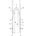
- FIG. 1 shows an example of a nunchaku lacrimal duct tube 1 (with a bougie inserted).
- This nunchaku-shaped lacrimal tube 1 is a cylindrical or rod-shaped central portion 4 and one end of the central portion 4 that are placed in the punctum, lacrimal tubule, total lacrimal tubule, and lacrimal sac at a substantially central portion.
- the central part 4 is formed thinner than the first cylindrical part 5a and the second cylindrical part 5b, and forms a so-called nunchaku type.
- the first end 6 of the first cylindrical portion 5a and the second end 8 of the second cylindrical portion 5b are blind ends, and the tips thereof have a sharp shape.
- the end of each cylindrical part may be opened.
- the distal end portion including the first end 6 is colored in order to make it easy for the operator to distinguish from the distal end portion including the second end 8.
- two marks 9a are attached at predetermined positions from the first end 6 of the first tubular portion 5a so that the operator can visually recognize the insertion depth.
- the second cylindrical portion 5b is also marked with a mark 9b.
- bougie insertion cuts 7a and 7b are arranged on the side walls in the vicinity of the central part 4 of the first cylindrical part 5a and the second cylindrical part 5b, respectively, and the first bougie is inserted through the cuts 7a and 7b.
- 2a and the 2nd bougie 2b are each inserted in the hollow part of the 1st cylindrical part 5a and the 2nd cylindrical part 5b.
- the center part 4 is provided with a midpoint mark 3 at a position which is substantially the center of the nunchaku lacrimal tube 1 so that the insertion position and the detention position can be easily confirmed.
- the coating layer (not shown) is formed on the surface of the first cylindrical part 5a and the second cylindrical part 5b and, if necessary, the central part 4.
- the medical tube of the present invention is an occlusion catheter as an example
- the material of the insertion member constituting the occlusion catheter will be described.
- the insertion member is a member that is inserted into a blood vessel and constitutes a portion that comes into contact with the blood vessel wall or the like.
- the material of the insertion member used in the occlusion catheter is not particularly limited.
- polyolefin resins such as polyolefin and polyolefin elastomer
- polyurethane resins such as polyurethane and polyurethane elastomer
- polyamide resins such as polyamide and polyamide elastomer
- polyethylene examples thereof include synthetic resins such as polyester resins such as terephthalate, silicone resins, and styrene resins such as styrene elastomers, and these can be used alone or in combination.
- these materials can be suitably selected according to the use of the insertion member.
- a reinforcing layer may be provided to reinforce the inner tube and / or the outer tube.
- the material constituting the inner layer is preferably a material having lubricity, and examples thereof include a fluorine resin such as polytetrafluoroethylene and a synthetic resin such as a polyolefin resin such as polyethylene. Furthermore, in order to change the hardness of the inner tube and / or the outer tube in the axial direction, a plurality of resins having different hardnesses may be arranged along the axial direction of the occlusion catheter.
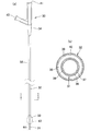
- FIG. 3A is a diagram schematically showing the structure of the occlusion catheter 30, and FIG. 3B is a diagram schematically showing the II cross section of FIG. 3A.
- the occlusion catheter of this embodiment includes a long tube composed of an inner tube 31 and an outer tube 32, a balloon 33, and a hub 34.
- the balloon 33 has a cylindrical structure, and the inner tube 31 passes through the cylindrical interior.
- the distal end of the balloon 33 is joined to the vicinity of the distal end of the inner tube 31, and the proximal end of the balloon 33 is joined to the distal end of the outer tube 32. Yes.
- the inner tube 31 is provided with a lumen 36 that is open at the distal end and the proximal end and communicates from the distal end to the proximal end, and is inserted through a guide wire, injected with a drug solution, discharged from a body fluid, and the like.
- the outer tube 32 includes a lumen that opens at the distal end and the proximal end and communicates from the distal end to the proximal end. Then, by arranging the inner tube 31 in the lumen portion, a portion (reference numeral 35 in FIG. 3B) constituted by the outer peripheral surface of the inner tube 31 and the inner peripheral surface of the outer tube 32 is formed.
- the This portion functions as a balloon lumen 35 through which a fluid for inflating the balloon 33 passes.
- the hub 34 communicates with the lumen 36 of the inner tube 31 and includes a first opening 41 used for guide wire insertion, drug injection, and the like.
- the hub 34 also includes a second opening 42 that communicates with the balloon lumen 35 and is used to inject and remove balloon fluid for inflating the balloon 33.
- the base material of the inner tube 31 has a two-layer structure of an inner layer 37 and an outer layer 38.
- a material for improving the guide wire insertion property as the material constituting the inner layer 37.
- the various resin mentioned above can be used for the material which comprises the outer layer 38.
- a plurality of resins having different hardnesses may be arranged so that the hardness gradually increases from the distal side toward the proximal side.
- a reinforcing layer may be further provided between the inner layer 37 and the outer layer 38.
- a radiopaque marker may be disposed in a portion disposed in the cavity 43.
- a known metal material can be used for the radiopaque marker.
- a coating layer is provided on a portion 44 that is not covered with the balloon 33 and the outer tube 32 at the distal end of the inner tube 31.
- the base material 39 of the outer tube 32 is a single layer in this embodiment, but it may have a multilayer structure like the base material of the inner tube 31, or a reinforcing layer may be provided. Moreover, you may change the hardness of an axial direction similarly to the base material of the inner pipe
- a coating layer 40 in which the specific intermediate layer and the lubricating layer are sequentially laminated is formed on the outer peripheral surface of the base material 39.
- the base material of the balloon 33 may have a single-layer structure or a multi-layer structure in a cross-section perpendicular to the axial direction of the occlusion catheter 30.
- the balloon 33 is preferably a compliant balloon whose outer diameter changes according to the amount of fluid injected into the lumen portion 43 of the balloon 33. Therefore, it is preferable to use a flexible material for the base material of the balloon 33, and examples thereof include polyurethane elastomer, silicone resin, polyamide resin, and the like.
- a coating layer in which the specific intermediate layer and the lubricating layer are sequentially laminated is formed on the outer peripheral surface of the base material of the balloon 33.
- a medical tube including an insertion member having a desired structure is produced. If the medical tube is a lacrimal tube, for example, a lacrimal tube having the structure shown in FIG. 1 (excluding the coating layer) is prepared, and if it is an occlusion catheter, the structure shown in FIG. An occlusion catheter having a coating layer is removed. Next, an intermediate layer and a lubricating layer can be sequentially formed on the surface of the insertion member of the medical tube.
- an intermediate layer and a lubricating layer are sequentially formed on the surface of each member, and then each member is assembled to manufacture a medical tube.
- an intermediate layer and a lubricating layer are sequentially formed at each manufacturing stage of the first cylindrical portion 5a, the second cylindrical portion 5b, and the central portion 4, and then assembled.
- the lacrimal tube 1 can be manufactured.
- many 1st, 2 cylindrical parts and center parts can be manufactured previously, and the production efficiency of a lacrimal duct tube can be improved.
- the members for example, the outer tube 32, the balloon 33, and the inner tube 31 in FIG.
- the occlusion catheter 30 may be manufactured by sequentially forming an intermediate layer and a lubricating layer on the surface of the tip portion, and then assembling the members.
- the method for forming the intermediate layer and the lubricating layer is not particularly limited.
- the intermediate layer obtained by mixing the coating composition containing the components (a), (b), and (c1) with a solvent.
- a lubricating layer coating solution prepared by mixing a coating composition containing the components (a), (b), (c2) (and, if necessary, further (c1)) and a solvent.
- the coating liquid for the lubricating layer is applied to the surface and dried, so that the intermediate layer and the lubricating layer are sequentially laminated on the surface of the insertion member.
- a layer can be formed.
- an intermediate layer coating solution and a lubricating layer coating solution are prepared .
- the lubricating layer coating solution may be prepared so as to contain 10 to 50% by weight of the intermediate layer coating solution.
- an intermediate layer coating solution having a predetermined coating composition concentration and a lubricating layer coating solution having a coating composition concentration equal to or higher than the coating composition concentration of the intermediate layer coating solution are prepared and used.
- a desired coating layer may be formed, and the concentration of the coating composition at that time is 0.1 to 10.0% by weight of the intermediate layer coating solution, and the lubricating layer coating solution is 1. It may be 0 to 10% by weight.
- the method of applying each coating liquid to the surface of the insertion member is not particularly limited, and for example, a method of applying the coating liquid by bringing the coating liquid into contact with the surface of the insertion member and adsorbing the coating composition on the surface of the insertion member, Each coating solution is soaked in the sponge or brush, for example, a method of applying the coating solution to the surface of the insertion member while moving the sponge or brush in the length direction of the insertion member, or spraying the coating solution on the surface of the insertion member.
- coating by dipping etc. are mentioned, However, It is not limited to these.
- the solvent used for preparing each coating liquid is not particularly limited.
- active hydrogen is used to prevent deterioration of the polyurethane-based resin produced by reacting the components (a) and (b) with time.
- a non-aqueous solvent having a solubility parameter value ⁇ having an appropriate affinity for the surface of the insertion member and having a solubility parameter value ⁇ of 8 to 13 [(cal / cm) 1/2 ] is preferable. More preferably, the non-aqueous solvent has a solubility parameter value ⁇ of 9 to 12.
- a volatile nonaqueous solvent particularly an organic solvent.
- halogenated hydrocarbons such as acetonitrile, tetrahydrofuran (THF), acetone, ethyl acetate, dichloromethane, and chloroform.
- THF and acetone are non-aqueous solvents having a solubility parameter value ⁇ of 9 to 12.
- the order of addition or reaction is not particularly limited, and the above (a), (b), Including at least part of the components (c1) and (c2) as prepolymers that have been reacted in advance, these prepolymers react with components (a), (b), (c1), and (c2) that have not been reacted.
- the reaction product may be used as a reaction product, or a mixture of unreacted components (a), (b), (c1), and (c2) may be reacted to obtain a reaction product.
- the reactive product of each diisocyanate of the component (a) and the trifunctional or higher functional polyol of the component (b) is added to the polyalkylene glycol and / or monomethoxy of the components (c1) and (c2).
- Add polyalkylene glycol It is preferable to be created to respond.
- a material obtained by adding a small amount of the component (b) to the component (a) is commercially available, and can be suitably used.
- each diisocyanate of component (a), a trifunctional or higher functional polyol of component (b), and polyalkylene glycol and / or monomethoxy polyalkylene glycol of components (c1) and (c2) are added and reacted.
- a reaction in a solution system is preferably used.
- the above-mentioned non-aqueous solvent having a predetermined solubility parameter value ⁇ of 8 to 13 [(cal / cm) 1/2 ] can be preferably used.
- the medical tube obtained by sequentially laminating the intermediate layer of the specific composition and the lubricating layer showing lubricity when wet on the surface of the insertion member obtained as described above has good lubricity when wet and has good insertability. It is good and the durability of the coating layer is further improved.
- the coating layer can be used particularly suitably when it is placed in the living body for a long period of time or when it is moved within the living body such as a bent blood vessel by a suitable distance.
- Friction durability (change in friction load) Measurement was performed in the same manner as in (1) of [Initial characteristics], and the ratio of the load value at 100 and 1000 reciprocations to the load value at 2 reciprocations was calculated.
- Example 1 ⁇ Manufacture of coating liquid> (1) Preparation of liquid A The following substances were charged into a 10 L reactor. 4,4'-diphenylmethane diisocyanate 6.0 [kg] The mixture was heated to 70 ° C. with stirring under a nitrogen stream, and the following substances were continuously added dropwise over 2 hours while continuing stirring. Castor oil 3.2 [kg] Furthermore, stirring was continued for 2 hours while maintaining the temperature at 70 ° C. under a nitrogen stream to obtain a polyurethane prepolymer.
- C liquid 25 g of 10 wt% THF solution of polyethylene glycol 4000 (PEG 4000) was added to 5 g of B liquid, heated to 40 ° C and stirred for 3 hours to obtain C liquid.
- concentration of components (coating composition) other than THF in the obtained C liquid is 10.8 weight%.
- the obtained liquid be C liquid (1).
- a portion of this C liquid (1) was diluted four times with THF to obtain C liquid (1/4) having a coating composition concentration of 2.7% by weight. Further, THF was added to a part of the liquid C (1) and diluted 8 times to obtain a liquid C (1/8) in which the concentration of the coating composition was 1.4% by weight.
- D liquid 25 g of 10 wt% THF solution of polyethylene glycol 35000 (PEG35000) was added to 1.25 g of B liquid, heated to 40 ° C and stirred for 3 hours to obtain D liquid. .
- concentration of components (coating composition) other than THF in obtained D liquid is 10.2 weight%.
- the obtained liquid be D liquid (1).
- Part of this D liquid (1) was diluted with THF four times to obtain D liquid (1/4) having a coating composition concentration of 2.6% by weight.
- Table 1 shows the composition / composition ratio of the liquid C (1) and the liquid D (1) and the composition ratio of the liquid E among the liquids (1) to (5) above.
- the E solution (1/4) obtained in (5) above is contained in the sponge as the lubricating layer coating solution, and the sponge is moved in parallel with the length of the tube with the tube on which the intermediate layer is formed from all sides. , E liquid (1/4) was applied. Then, it was made to dry at 40 degreeC for 6 minute (s), and the tube with which the intermediate
- Example 2 Manufacture of coating liquid>
- a liquid, B liquid, C liquid (1), C liquid (1/4), C liquid (1/8), D liquid (1), D liquid (1/4) and E liquid (1/4) were prepared.
- THF was added to a part of solution C (1) to dilute it 16 times, and solution C (1) with a coating composition concentration of 0.57% by weight was obtained.
- solution C (1) with a coating composition concentration of 0.57% by weight was obtained.
- solution C (1) with a coating composition concentration of 0.57% by weight was obtained.
- Example 3 Manufacture of coating liquid>
- a liquid, B liquid, C liquid (1), C liquid (1/2), D liquid (1), and D liquid (1/2) Prepared.
- the same amount of liquid C (1/2) and liquid D (1/2) having the same dilution ratio of the coating composition were mixed and stirred at 40 ° C. for 1 hour to obtain liquid H (1/2).
- the composition ratio of solution H is shown in Table 1.
- Solution A was prepared in the same manner as in Example 1. 1.2 g of the above solution A, 0.3 g of castor oil and 8.5 g of THF were added and stirred well. Next, 80.1 g of a 10 wt% THF solution of polyethylene glycol 20000 (PEG 20000) was added, the temperature was raised to 40 ° C., and the mixture was stirred for 3 hours to prepare solution F.
- PEG 20000 polyethylene glycol 20000
- a tube was produced in the same manner as in Example 1.
- the obtained F solution was included in a sponge, the tube was sandwiched from all sides, the sponge was moved in parallel with the length direction of the tube, and the F solution was applied. Thereafter, the tube was dried at 40 ° C. for 6 minutes to obtain a tube having only a lubricating layer formed on the tube surface.
- Each evaluation test described above was performed on the obtained tube. The evaluation results are shown in Table 2.
- the obtained G liquid is put in a container for immersion (depth of about 70 mm), and the tube is lowered at a constant speed of 5 mm / sec to immerse a predetermined portion in the G liquid, and immediately after that, the length of the tube is increased at the same speed.
- the film was pulled up parallel to the direction and dried at room temperature for 5 seconds. This series of operations was repeated 5 times, and then dried at 40 ° C. for 6 minutes to obtain a tube in which only a wet layer was formed on the surface of the tube.
- the evaluation results are shown in Table 2.
- Example 1 From Tables 2 and 3, from the comparison between Example 1 and Comparative Example 1 and the comparison between Example 3 and Comparative Example 5, in the case of a tube having two coating layers of an intermediate layer and a wet layer, The evaluation result is superior to the case of only one lubricating layer, and it can be seen that the durability is improved by providing a predetermined intermediate layer. From the result of Example 1, it can be expected to be applied to a medical catheter used for an application that requires long-term indwelling in the living body. From the result of Example 3, for example, it is necessary to insert a bent part in the living body. Application to medical catheters used for applications can be expected. According to Comparative Examples 1 to 3, although there are differences in the evaluation results of the appearance of the initial characteristics depending on the coating method, the friction loads of the initial characteristics are all good results. It was suggested that the same result was obtained when two coating layers were formed.
Abstract
Description
ところで、この涙道閉塞の治療には、(i)涙道ブジーによるプロービング、(ii)涙道チューブの留置、(iii)涙嚢鼻腔吻合術(DCR)、(iv)涙小管形成術、(v)鼻涙管形成術、(vi)涙丘移動術などがある。 First, the lacrimal tube will be described. This lacrimal duct tube is a therapeutic tube used for the treatment of lacrimal passage obstruction that causes lacrimation.
By the way, treatment of this lacrimal passage obstruction includes (i) probing with lacrimal passage bougie, (ii) placement of lacrimal passage tube, (iii) lacrimal nasal sinus anastomosis (DCR), (iv) lacrimal tube formation, ( There are v) nasolacrimal duct surgery, (vi) lacrimal mobilization.
〔1〕生体内へ挿入される挿入部材の表面に、下記(a)、(b)、(c1)を含有する組成物からなる中間層と、下記(a)、(b)、(c2)を含有する組成物からなる潤滑層とが順次積層された医療用チューブ;
(a)芳香族ジイソシアネート、脂肪族ジイソシアネート、および脂環族ジイソシアネートの少なくとも1種1~35重量%、
(b)3官能以上のポリオール1~35重量%、
(c1)ポリアルキレングリコール及び/又はモノメトキシポリアルキレングリコール30~98重量%、
(c2)ポリアルキレングリコール(重量平均分子量が(c1)のポリアルキレングリコールよりも大きいものが含まれる)及び/又はモノメトキシポリアルキレングリコール(重量平均分子量が(c1)のモノメトキシポリアルキレングリコールよりも大きいものが含まれる)30~98重量%、
(但し、(c1)、(c2)に関し、各グリコールはジオールである。)。
〔2〕前記(c2)の成分として、前記(c1)の成分が10~50重量%含まれる前記〔1〕記載の医療用チューブ。
〔3〕前記(a)、(b)、(c1)の成分及び溶媒を含有する中間層用コーティング液、並びに、前記(a)、(b)、(c2)の成分及び溶媒を含有する潤滑層用コーティング液を塗布、乾燥させて得られる前記〔1〕又は〔2〕記載の医療用チューブにおいて、前記中間層用コーティング液における(a)、(b)、(c1)の成分の合計濃度が、潤滑層用コーティング液における(a)、(b)、(c2)の成分の合計濃度以下である医療用チューブ。
〔4〕前記中間層用コーティング液における(a)、(b)、(c1)の成分の合計濃度が0.1~10重量%であり、前記潤滑層用コーティング液における(a)、(b)、(c2)の成分の合計濃度が、1.0~10重量%である前記〔3〕記載の医療用チューブ。
〔5〕前記中間層の組成物が、前記(a)、(b)、(c1)の成分の少なくとも一部を反応させたプレポリマーを含有してなる、及び/又は、前記潤滑層の組成物が前記(a)、(b)、(c1)、(c2)の成分の少なくとも一部を反応させたプレポリマーを含有してなる前記〔1〕~〔4〕の何れかに記載の医療用チューブ。
〔6〕前記中間層の組成物が、前記(a)、(b)、(c1)の成分を反応させた反応生成物である、及び/又は、前記潤滑層の組成物が前記(a)、(b)、(c1)、(c2)の成分を反応させた反応生成物である前記〔1〕~〔5〕の何れかに記載の医療用チューブ。
〔7〕前記挿入部材を構成する材質が、シリコーン樹脂、イソブチレン系ブロック共重合体、熱可塑性ポリウレタン系樹脂、ポリアミド系樹脂からなる群から選択された少なくとも1種を含む前記〔1〕~〔6〕の何れかに記載の医療用チューブ。
〔8〕前記医療用チューブが、涙道内に挿入され、留置される涙道チューブである前記〔1〕~〔7〕の何れかに記載の医療用チューブ。
〔9〕前記挿入部材を構成する材質が、イソブチレン系ブロック共重合体を含有した熱可塑性ポリウレタン系樹脂を含む前記〔8〕記載の医療用チューブ。
〔10〕前記〔1〕~〔9〕の何れかに記載の医療用チューブの製造方法であって、前記(a)、(b)、(c1)の成分及び溶媒を含有する中間層用コーティング液を調製した後、該中間層用コーティング液を10~50重量%含むように前記(a)、(b)、(c2)の成分及び溶媒を含有する潤滑層用コーティング液を調製する工程を含む医療用チューブの製造方法。
〔11〕前記(a)、(b)、(c1)の成分及び溶媒を含有する中間層用コーティング液を前記挿入部材に塗布し、乾燥させた後、前記(a)、(b)、(c2)の成分の合計濃度が前記中間層用コーティング液の(a)、(b)、(c1)の成分の合計濃度以上である潤滑層用コーティング液を塗布し、乾燥させて、前記挿入部材の表面に中間層と潤滑層を順次積層する工程を含む、前記〔9〕記載の医療用チューブの製造方法。
〔12〕前記中間層用コーティング液における(a)、(b)、(c1)の成分の合計濃度が0.1~10重量%であり、前記潤滑層用コーティング液における(a)、(b)、(c2)の成分の合計濃度が、1.0~10重量%である前記〔11〕記載の医療用チューブの製造方法。
〔13〕前記中間層用コーティング液及び/又は前記潤滑層用コーティングを前記留置
部材に塗布する工程が、ディッピング、中間層用コーティング液及び/又は前記潤滑層用
コーティングを含むスポンジによる塗布、中間層用コーティング液及び/又は前記潤滑層
用コーティングを含む刷毛による塗布、又は、噴霧である前記〔10〕~〔12〕の何れかに記載の医療用チューブの製造方法。 The gist of the present invention is as follows.
[1] An intermediate layer made of a composition containing the following (a), (b), and (c1) on the surface of an insertion member to be inserted into a living body, and the following (a), (b), (c2) A medical tube in which a lubricating layer made of a composition containing sucrose is sequentially laminated;
(A) 1 to 35% by weight of at least one of aromatic diisocyanate, aliphatic diisocyanate, and alicyclic diisocyanate,
(B) 1 to 35% by weight of a tri- or higher functional polyol,
(C1) 30 to 98% by weight of polyalkylene glycol and / or monomethoxy polyalkylene glycol,
(C2) polyalkylene glycol (including those having a weight average molecular weight larger than that of (c1) polyalkylene glycol) and / or monomethoxy polyalkylene glycol (weight average molecular weight of (c1) than monomethoxy polyalkylene glycol) 30 to 98% by weight)
(However, regarding (c1) and (c2), each glycol is a diol).
[2] The medical tube according to [1], wherein the component (c1) is contained in an amount of 10 to 50% by weight as the component (c2).
[3] An intermediate layer coating solution containing the components (a), (b) and (c1) and a solvent, and a lubricant containing the components (a), (b) and (c2) and a solvent. In the medical tube according to [1] or [2] obtained by applying and drying a layer coating solution, the total concentration of the components (a), (b), and (c1) in the intermediate layer coating solution Is a medical tube having a concentration equal to or lower than the total concentration of the components (a), (b), and (c2) in the lubricating layer coating solution.
[4] The total concentration of the components (a), (b), and (c1) in the intermediate layer coating solution is 0.1 to 10% by weight, and (a), (b ), (C2) The medical tube according to [3] above, wherein the total concentration of the components is 1.0 to 10% by weight.
[5] The composition of the intermediate layer contains a prepolymer obtained by reacting at least part of the components (a), (b), and (c1), and / or the composition of the lubricating layer. The medical device according to any one of [1] to [4], wherein the product contains a prepolymer obtained by reacting at least a part of the components (a), (b), (c1), and (c2). For tubes.
[6] The composition of the intermediate layer is a reaction product obtained by reacting the components (a), (b), and (c1), and / or the composition of the lubricating layer is the component (a). The medical tube according to any one of [1] to [5], which is a reaction product obtained by reacting the components (b), (c1), and (c2).
[7] The above [1] to [6], wherein the material constituting the insertion member includes at least one selected from the group consisting of a silicone resin, an isobutylene block copolymer, a thermoplastic polyurethane resin, and a polyamide resin. ] The medical tube in any one of.
[8] The medical tube according to any one of [1] to [7], wherein the medical tube is a lacrimal tube that is inserted into the lacrimal tract and placed therein.
[9] The medical tube according to [8], wherein the material constituting the insertion member includes a thermoplastic polyurethane resin containing an isobutylene block copolymer.
[10] The method for producing a medical tube according to any one of [1] to [9], wherein the coating for intermediate layer contains the components (a), (b) and (c1) and a solvent. A step of preparing a lubricating layer coating solution containing the components (a), (b) and (c2) and a solvent so as to contain 10 to 50% by weight of the intermediate layer coating solution. A method for producing a medical tube.
[11] An intermediate layer coating solution containing the components (a), (b), and (c1) and a solvent is applied to the insertion member and dried, and then the components (a), (b), ( c2), a lubricating layer coating solution having a total concentration of (a), (b), and (c1) components equal to or higher than the total concentration of the intermediate layer coating solution is applied, dried, and then inserted. The method for producing a medical tube according to the above [9], comprising a step of sequentially laminating an intermediate layer and a lubricating layer on the surface.
[12] The total concentration of the components (a), (b), and (c1) in the intermediate layer coating solution is 0.1 to 10% by weight, and (a), (b ), (C2), wherein the total concentration of the components is 1.0 to 10% by weight.
[13] The step of applying the intermediate layer coating liquid and / or the lubricating layer coating to the indwelling member includes dipping, applying with a sponge including the intermediate layer coating liquid and / or the lubricating layer coating, and the intermediate layer The method for producing a medical tube according to any one of the above [10] to [12], wherein the coating solution is a coating solution and / or a brush containing the lubricating layer coating or spraying.
また、医療用チューブが例えば涙道チューブである場合は、涙道チューブの表面が湿潤時に十分な潤滑性を有するため、涙道壁とチューブとに生じる摩擦を軽減することができ、仮道を形成するほどの力がかかる場合には、手元の抵抗が大きくなることから、手元にかかる抵抗の違いにより仮道の形成を認識できるため、過負荷をかけることがなくなり、涙道チューブの突き抜けや仮道形成なく、湾曲又は閉塞した涙道内へ容易に正しく涙道チューブを挿入し、留置することが可能である。また、留置部材の表面に特定の組成物からなる中間層と潤滑層を順次積層していることから、耐久性が向上しており、長期的(例えば、2週間~2ヶ月程度)な留置が想定されている涙道チューブとして好適である。
更に、医療用チューブが例えばオクリュージョンカテーテル等の屈曲した血管等に挿入されるカテーテルである場合は、オクリュージョンカテーテルの表面が湿潤時に十分な潤滑性を有していることから血管壁等との接触抵抗が低減されることで挿入性が向上し、また、耐久性が向上していることから、血管の屈曲部の通過時に相応の距離だけ挿通させた場合でも、潤滑層が脱落することを抑制することができる。 According to the present invention, since the lubricating layer made of a specific composition has sufficient lubricity when the surface of the insertion member is wet, the medical tube can be easily inserted into the living body, and the durability is improved compared to the conventional case. Therefore, the lubricant layer can be prevented from falling off from the surface of the insertion member.
In addition, when the medical tube is a lacrimal tube, for example, the surface of the lacrimal tube has sufficient lubricity when wet, so that friction generated between the lacrimal wall and the tube can be reduced. When the force is high enough to form, the resistance at hand increases, so the formation of a temporary path can be recognized due to the difference in resistance applied at hand, so there is no overload, and the tear path tube penetrates and It is possible to easily insert and place the lacrimal tube easily into the curved or closed lacrimal passage without forming a temporary tract. Further, since an intermediate layer made of a specific composition and a lubricating layer are sequentially laminated on the surface of the indwelling member, durability is improved, and indwelling for a long time (for example, about 2 weeks to 2 months) is achieved. It is suitable as the assumed lacrimal duct tube.
Furthermore, when the medical tube is a catheter that is inserted into a bent blood vessel such as an occlusion catheter, the surface of the occlusion catheter has sufficient lubricity when wet, so that the vessel wall and the like Since the insertion resistance is improved by reducing the contact resistance with and the durability is improved, the lubricating layer falls off even if it is inserted through a suitable distance when passing through the bent part of the blood vessel. This can be suppressed.
本発明は、生体内へ留置される挿入部材の表面に、下記(a)、(b)、(c1)を含有する組成物からなる中間層と、下記(a)、(b)、(c2)を含有する組成物からなる潤滑層とが順次積層された医療用チューブであり、下記(c1)、(c2)に関しては、各グリコールはジオールである。
(a)芳香族ジイソシアネート、脂肪族ジイソシアネート、および脂環族ジイソシアネ
ートの少なくとも1種1~35重量%、
(b)3官能以上のポリオール1~35重量%、
(c1)ポリアルキレングリコール及び/又はモノメトキシポリアルキレングリコール30~98重量%、
(c2)ポリアルキレングリコール(重量平均分子量が(c1)のポリアルキレングリコールよりも大きいものが含まれる)及び/又はモノメトキシポリアルキレングリコール(重量平均分子量が(c1)のモノメトキシポリアルキレングリコールよりも大きいものが含まれる)30~98重量%。
尚、以下では、(a)、(b)、(c1)、(c2)を含有する組成物を「コーティング組成物」と称する場合がある。 Hereinafter, the present invention will be described in detail.
The present invention provides an intermediate layer comprising a composition containing the following (a), (b), and (c1) on the surface of an insertion member to be placed in a living body, and the following (a), (b), (c2): ) And a lubricating layer made of a composition containing the same in order, and in the following (c1) and (c2), each glycol is a diol.
(A) 1 to 35% by weight of at least one of aromatic diisocyanate, aliphatic diisocyanate, and alicyclic diisocyanate,
(B) 1 to 35% by weight of a tri- or higher functional polyol,
(C1) 30 to 98% by weight of polyalkylene glycol and / or monomethoxy polyalkylene glycol,
(C2) polyalkylene glycol (including those having a weight average molecular weight larger than that of (c1) polyalkylene glycol) and / or monomethoxy polyalkylene glycol (weight average molecular weight of (c1) than monomethoxy polyalkylene glycol) 30 to 98% by weight.
Hereinafter, the composition containing (a), (b), (c1), and (c2) may be referred to as a “coating composition”.
特に、潤滑層のポリアルキレングリコールとモノメトキシポリアルキレングリコールの重量平均分子量が、中間層のそれより大きいものを含むことで、潤滑層は、湿潤時には、(c2)成分による十分な潤滑性を有する。また、中間層では、(c1)成分であるポリアルキレングリコール及び/又はモノメトキシポリアルキレングリコールの重量平均分子量が相対的に小さいものを用いることで、潤滑層との親和性を保持しつつ、(a)及び(b)成分に基づく、挿入部材の表面との接合強度を向上させることが可能となる。 In the present invention, the lubricating layer comprising the composition containing the component (c2) having a weight average molecular weight different from the component (c1) of the intermediate layer on the surface of the intermediate layer comprising the specific composition as described above. The intermediate layer and the lubricating layer are laminated.
In particular, when the weight average molecular weight of the polyalkylene glycol and the monomethoxy polyalkylene glycol in the lubricating layer is larger than that in the intermediate layer, the lubricating layer has sufficient lubricity due to the component (c2) when wet. . In the intermediate layer, the polyalkylene glycol and / or monomethoxy polyalkylene glycol (c1) component having a relatively low weight average molecular weight is used, while maintaining the affinity with the lubricating layer ( It becomes possible to improve the bonding strength with the surface of the insertion member based on the components a) and (b).
また、(c1)、(c2)で用いることができるモノメトキシポリアルキレングリコールとしては、本発明の効果が発揮される限り、特に限定はなく、例えば、モノメトキシポリエチレングリコール、モノメトキシポリプロピレングリコールが挙げられる。
また、これらの誘導体としては、本発明の効果が発揮される限り、特に限定はなく、例えば、グリセリンのトリポリエチレングリコールエーテル、ジグリセリンのテトラポリエチレングリコールエーテル、ペンタエリスリトールのテトラポリエチレングリコールエーテル等が挙げられる。
また、本発明では、(c1)、(c2)で用いるポリアルキレングリコール及びモノメトキシポリアルキレングリコールは、上記の誘導体を含めてジオールである。 The polyalkylene glycol that can be used in (c1) and (c2) is not particularly limited as long as the effects of the present invention are exhibited, and examples thereof include polyethylene glycol and polypropylene glycol.
Further, the monomethoxypolyalkylene glycol that can be used in (c1) and (c2) is not particularly limited as long as the effect of the present invention is exhibited, and examples thereof include monomethoxypolyethylene glycol and monomethoxypolypropylene glycol. It is done.
These derivatives are not particularly limited as long as the effects of the present invention are exhibited. Examples thereof include glycerin tripolyethylene glycol ether, diglycerin tetrapolyethylene glycol ether, and pentaerythritol tetrapolyethylene glycol ether. It is done.
In the present invention, the polyalkylene glycol and monomethoxy polyalkylene glycol used in (c1) and (c2) are diols including the above derivatives.
また、後者の場合は、例えば、潤滑層の(c2)のポリアルキレングリコール及び/又はモノメトキシポリアルキレングリコール成分には、中間層の(c1)のそれ(又はそれら)が、好ましくは10~50重量%、より好ましくは15~45重量%、更に好ましくは20~40重量%含まれるように構成してもよい。これにより、中間層と潤滑層の耐久性が保持されることとなる。 In the present invention, each glycol of (c2) of the lubricating layer includes one whose weight average molecular weight is larger than the weight average molecular weight of each glycol of (c1) of the intermediate layer. All of the glycols in the lubricating layer may have a weight average molecular weight larger than that of the intermediate layer, or a part thereof may have a weight average molecular weight equal to or less than that of the intermediate layer.
In the latter case, for example, the (c2) polyalkylene glycol and / or monomethoxypolyalkylene glycol component of the lubricating layer preferably has (c1) (or those) of the intermediate layer preferably 10 to 50. You may comprise so that it may be contained by weight%, More preferably, 15 to 45 weight%, More preferably, 20 to 40 weight%. Thereby, durability of an intermediate | middle layer and a lubricating layer will be hold | maintained.
また、この際の、各コーティング液中のコーティング組成物の濃度は、上記の関係を維持できれば、特に限定はないが、中間層用コーティング液の濃度が、好ましくは0.1~10重量%であり、より好ましくは0.15~9.0重量%、更に好ましくは0.2~8.0重量%の範囲であり、潤滑層用コーティング液の濃度が、好ましくは1.0~10重量%であり、より好ましくは1.1~9.0重量%、更に好ましくは1.2~8.0重量%の範囲である。ただし涙道チューブは、長期的な留置が想定されるため、より薄い濃度である事が望ましく、中間層用コーティング液の濃度が、好ましくは0.20~5.0重量%であり、より好ましくは0.60~4.0重量%、更に好ましくは0.70~3.0重量%の範囲であり、潤滑層用コーティング液の濃度が、好ましくは1.0~10重量%であり、より好ましくは1.1~9.0重量%、更に好ましくは1.2~8.0重量%の範囲である。上記の濃度の大小関係を保持しつつ、それぞれのコーティング液をこのような濃度範囲とすることにより、中間層と潤滑層の耐久性かつ潤滑層の潤滑性が保持されることとなる。 In the present invention, when the intermediate layer and the lubricating layer are formed on the surface of the insertion member, the intermediate layer coating liquid and the lubricating layer coating liquid are prepared. And the total concentration of the above (a), (b), (c1) in the intermediate layer coating solution, the total concentration of (a), (b), (c2) in the lubricating layer coating solution, that is, As the relationship of the concentration of the coating composition, the concentration of the intermediate layer coating liquid is preferably equal to or lower than the concentration of the lubricating layer coating liquid. This ensures the film thickness of the finally formed lubricating layer, maintains sufficient lubricity, reduces the film thickness of the intermediate layer, and ensures the bonding strength between the lubricating layer and the surface of the indwelling member. be able to.
In this case, the concentration of the coating composition in each coating solution is not particularly limited as long as the above relationship can be maintained, but the concentration of the coating solution for the intermediate layer is preferably 0.1 to 10% by weight. More preferably 0.15 to 9.0% by weight, still more preferably 0.2 to 8.0% by weight, and the concentration of the lubricating layer coating solution is preferably 1.0 to 10% by weight. More preferably, it is in the range of 1.1 to 9.0% by weight, still more preferably 1.2 to 8.0% by weight. However, since the lacrimal tube is assumed to be indwelled for a long period of time, it is desirable that the concentration is lower, and the concentration of the coating solution for the intermediate layer is preferably 0.20 to 5.0% by weight, more preferably. Is in the range of 0.60 to 4.0 wt%, more preferably 0.70 to 3.0 wt%, and the concentration of the lubricating layer coating solution is preferably 1.0 to 10 wt%, and more The range is preferably 1.1 to 9.0% by weight, more preferably 1.2 to 8.0% by weight. By maintaining each of the coating liquids in such a concentration range while maintaining the above-described concentration relationship, the durability of the intermediate layer and the lubricating layer and the lubricity of the lubricating layer are maintained.
本発明で使用可能な挿入部材の材質は、医療用チューブとして一般的に使用可能な材質を用いることができ、例えば、ポリオレフィン系樹脂、ポリウレタン系樹脂、ポリアミド系樹脂、シリコーン系樹脂、ポリエステル系樹脂、イソブチレン系共重合体、ポリカーボネート、ポリ塩化ビニル、及び、これらのアロイ等を含む樹脂組成物が挙げられる。 The material of the insertion member which comprises the medical tube of this invention is demonstrated. The insertion member means a member that constitutes a portion of the medical tube that is inserted into the living body and is not located in the living body but is in contact with the living body or the liquid derived from the living body, as well as the portion that is placed in the living body. To do.
The material of the insertion member that can be used in the present invention can be a material that can be generally used as a medical tube. For example, polyolefin resin, polyurethane resin, polyamide resin, silicone resin, polyester resin , Isobutylene copolymers, polycarbonate, polyvinyl chloride, and resin compositions containing these alloys.
本発明の涙道チューブで用いる留置部材の材質は特に限定されず、例えば、シリコーン樹脂、ポリウレタン、ポリウレタン系樹脂、イソブチレン系共重合体、及び、これらのアロイ等を含む樹脂組成物を用いることが可能である。
本発明では、イソブチレン系共重合体とポリウレタン系樹脂とのアロイを含む樹脂組成物を好適に用いることができる。中でも、イソブチレン系共重合体としてイソブチレン系ブロック共重合体、ポリウレタン系樹脂として熱可塑性ポリウレタン系樹脂を用いた樹脂組成物を用いるのが好ましい。
イソブチレン系ブロック共重合体(A)と熱可塑性ポリウレタン系樹脂(B)からなる樹脂の場合、イソブチレン系ブロック共重合体(A)と、熱可塑性ポリウレタン系樹脂(B)との割合を調整することで、留置部材(以下、単に「チューブ」と称する場合がある。)の硬さを調整できる。例えば、熱可塑性ポリウレタン系樹脂(B)の割合を大きく設定するほど、チューブの硬度を大きくすることができる。
このように、(A)と(B)の混合割合は、適宜設定することができるが、抗血栓性、表面滑り性、柔軟性の観点からは、イソブチレン系ブロック共重合体(A)が1重量%以上(イソブチレン系ブロック共重合体(A)と熱可塑性ポリウレタン系樹脂(B)の割合が、重量比で(A)/(B)=1/99以上)含まれていることが好ましい。耐摩耗性の観点からは、イソブチレン系ブロック共重合体(A)と熱可塑性ポリウレタン系樹脂(B)の割合が、重量比で(A)/(B)=1/99~70/30であることが好ましい。圧縮応力の観点からは、イソブチレン系ブロック共重合体(A)と熱可塑性ポリウレタン系樹脂(B)の割合が、重量比で(A)/(B)=1/99~50/50であることが好ましい。 Taking the case where the medical tube of the present invention is a lacrimal duct tube as an example, the material of the insertion member constituting the lacrimal duct tube will be described. In the following, the insertion member constituting the lacrimal duct tube will be referred to as “indwelling member”. Moreover, the material mentioned later can be used according to the use of not only a lacrimal duct tube but a medical tube. In the lacrimal duct tube, the indwelling member means all members constituting the lacrimal duct tube described later. Taking the case of a nunchaku lacrimal duct tube, which will be described later, as an example, a cylindrical or rod-shaped central part and cylindrical members connected to both ends of the central part are included.
The material of the indwelling member used in the lacrimal duct tube of the present invention is not particularly limited. For example, a silicone resin, polyurethane, polyurethane resin, isobutylene copolymer, and a resin composition containing these alloys or the like may be used. Is possible.
In the present invention, a resin composition containing an alloy of an isobutylene copolymer and a polyurethane resin can be suitably used. Among them, it is preferable to use a resin composition using an isobutylene block copolymer as the isobutylene copolymer and a thermoplastic polyurethane resin as the polyurethane resin.
In the case of a resin comprising an isobutylene block copolymer (A) and a thermoplastic polyurethane resin (B), the ratio of the isobutylene block copolymer (A) and the thermoplastic polyurethane resin (B) is adjusted. Thus, the hardness of the indwelling member (hereinafter sometimes simply referred to as “tube”) can be adjusted. For example, the hardness of the tube can be increased as the proportion of the thermoplastic polyurethane resin (B) is set larger.
Thus, the mixing ratio of (A) and (B) can be set as appropriate. From the viewpoint of antithrombogenicity, surface slipperiness and flexibility, the isobutylene block copolymer (A) is 1 It is preferable that it is contained by weight ratio (the ratio of isobutylene block copolymer (A) and thermoplastic polyurethane resin (B) is (A) / (B) = 1/99 or more) by weight. From the viewpoint of wear resistance, the ratio of the isobutylene block copolymer (A) and the thermoplastic polyurethane resin (B) is (A) / (B) = 1/99 to 70/30 in weight ratio. It is preferable. From the viewpoint of compressive stress, the ratio of the isobutylene block copolymer (A) and the thermoplastic polyurethane resin (B) is (A) / (B) = 1/99 to 50/50 in weight ratio. Is preferred.
熱可塑性ポリウレタン系樹脂(B)としては、例えば、エーテル系芳香環式ポリウレタンである日本ミラクトラン社製の「ミラクトラン(登録商標)E385PNAT」、Lubrizol社製「テコタンTT1074A」、エーテル系脂環式ポリウレタンであるLubrizol社製の「テコフレックスEG100A」、「テコフレックスEG85A」、ポリカーボネート系ポリウレタンであるLubrizol社製「カルボタンPC3575A」などを用いることができるが、これらに限定されるものではない。 As the isobutylene-based block copolymer (A), for example, “SIBSTAR (registered trademark) 102T” manufactured by Kaneka Corporation, which is a styrene-isobutylene-styrene block copolymer (hereinafter sometimes referred to as SIBS), is used. Yes, but not limited to this.
As the thermoplastic polyurethane resin (B), for example, “Milactolan (registered trademark) E385PNAT” manufactured by Nippon Milactolan, which is an ether-based aromatic polyurethane, “Tecotan TT1074A” manufactured by Lubrizol, and ether-based alicyclic polyurethane are used. There can be used “Tecoflex EG100A”, “Tecoflex EG85A” manufactured by Lubrizol, and “Cal Button PC3575A” manufactured by Lubrizol, which is a polycarbonate-based polyurethane, but is not limited thereto.
図1は、ヌンチャク型の涙道チューブ1(ブジーを挿入した状態のもの)の一例を示したものである。このヌンチャク型の涙道チューブ1は、略中央部分に、涙点、涙小管、総涙小管、涙嚢に留置される部位となる、筒形状またはロッド形状の中央部4、中央部4の一端に連設され、涙嚢、鼻涙管、Hanser valve、下鼻道に留置される部位となる、筒形状の第1筒状部5a、中央部4の他端に連設され、涙嚢、鼻涙管、Hanser valve、下鼻道に留置される部位となる、筒形状の第2筒状部5bから構成される。中央部4は、第1筒状部5aおよび第2筒状部5bよりも細く形成され、いわゆるヌンチャク型を形成している。 The structure of the lacrimal tube of the present invention is not particularly limited as long as it can be inserted and placed in the lacrimal passage as described above. For example, the so-called nunchaku-type lacrimal tube can be employed. The nunchaku-type lacrimal duct tube will be briefly described with reference to the drawings.
FIG. 1 shows an example of a nunchaku lacrimal duct tube 1 (with a bougie inserted). This nunchaku-shaped
オクリュージョンカテーテルにおいて挿入部材とは、血管内に挿入され、血管壁等と接触する部分を構成する部材であり、後述する実施形態では、内管(特に遠位側端部)、外管及びバルーンの基材である。
オクリュージョンカテーテルで用いる挿入部材の材質は、特に限定されず、例えば、ポリオレフィン、ポリオレフィンエラストマー等のポリオレフィン系樹脂、ポリウレタン、ポリウレタンエラストマー等のポリウレタン系樹脂、ポリアミド、ポリアミドエラストマー等のポリアミド系樹脂、ポリエチレンテレフタレート等のポリエステル系樹脂、シリコーン系樹脂、スチレンエラストマー等のスチレン系樹脂等の合成樹脂が挙げられ、これらを1種又は2種以上用いることができる。また、これらの材質は、挿入部材の用途に応じて適宜選択することができる。
また、内管及び外管の基材を多層構造にする場合は、これらの合成樹脂を含む層が中間層と接するように、挿入部材の表面に配置するのが好ましい。また、このように多層構造にする場合に、内管及び/又は外管を補強するために、補強層を設けても良い。補強層を構成する材質は、例えば、ステンレス、タングステン、C-Mn-Si-P-S-Cr-Mo-Ni-Fe-X(X=Au,Os,Pd,Re,Ta,Ir,Ru)合金、C-Mn-Si-P-S-Cr-Mo-Ni-X(X=Au,Os,Pd,Re,Ta,Ir,Ru)合金、銅、ニッケル、チタン、ピアノ線、Co-Cr合金、Ni-Ti合金、Ni-Ti-Co合金、Ni-Al合金、Cu-Zn合金、Cu-Zn-X合金(例えば、X=Be、Si、Sn、Al、Ga)のような合金、アモルファス合金等の各種金属が挙げられる。更に、内管の内側にはガイドワイヤの挿通性を向上させるために内層を設けても良い。内層を構成する材質は、潤滑性を有する材質が好ましく、例えば、ポリテトラフルオロエチレン等のフッ素系樹脂、ポリエチレン等のポリオレフィン系樹脂等の合成樹脂が挙げられる。
更に、内管及び/又は外管の軸方向の硬さを変化させるために、オクリュージョンカテーテルの軸方向に沿って硬度が異なる樹脂を複数配置してもよい。 Taking the case where the medical tube of the present invention is an occlusion catheter as an example, the material of the insertion member constituting the occlusion catheter will be described.
In the occlusion catheter, the insertion member is a member that is inserted into a blood vessel and constitutes a portion that comes into contact with the blood vessel wall or the like. In the embodiment described later, an inner tube (particularly a distal end), an outer tube, It is the base material of the balloon.
The material of the insertion member used in the occlusion catheter is not particularly limited. For example, polyolefin resins such as polyolefin and polyolefin elastomer, polyurethane resins such as polyurethane and polyurethane elastomer, polyamide resins such as polyamide and polyamide elastomer, polyethylene Examples thereof include synthetic resins such as polyester resins such as terephthalate, silicone resins, and styrene resins such as styrene elastomers, and these can be used alone or in combination. Moreover, these materials can be suitably selected according to the use of the insertion member.
Moreover, when making the base material of an inner tube and an outer tube into a multilayer structure, it is preferable to arrange | position on the surface of an insertion member so that the layer containing these synthetic resins may contact | connect an intermediate | middle layer. Further, in the case of a multilayer structure as described above, a reinforcing layer may be provided to reinforce the inner tube and / or the outer tube. The material constituting the reinforcing layer is, for example, stainless steel, tungsten, C—Mn—Si—PS—Cr—Mo—Ni—Fe—X (X = Au, Os, Pd, Re, Ta, Ir, Ru). Alloy, C—Mn—Si—PS—Cr—Mo—Ni—X (X = Au, Os, Pd, Re, Ta, Ir, Ru) alloy, copper, nickel, titanium, piano wire, Co—Cr Alloys such as alloys, Ni—Ti alloys, Ni—Ti—Co alloys, Ni—Al alloys, Cu—Zn alloys, Cu—Zn—X alloys (eg, X = Be, Si, Sn, Al, Ga), Various metals, such as an amorphous alloy, are mentioned. Further, an inner layer may be provided on the inner side of the inner tube in order to improve the guide wire insertion property. The material constituting the inner layer is preferably a material having lubricity, and examples thereof include a fluorine resin such as polytetrafluoroethylene and a synthetic resin such as a polyolefin resin such as polyethylene.
Furthermore, in order to change the hardness of the inner tube and / or the outer tube in the axial direction, a plurality of resins having different hardnesses may be arranged along the axial direction of the occlusion catheter.
図3(a)は、オクリュージョンカテーテル30の構造を模式的に示した図であり、図3(b)は、図3(a)のI-I断面を模式的に示した図である。図3に示すように、本実施形態のオクリュージョンカテーテルは、内管31と外管32とで構成される長尺のチューブと、バルーン33と、ハブ34とを備える。
バルーン33は円筒状の構造を有し、円筒状の内部を内管31が貫通している。そして、バルーン33の遠位側端部は、内管31の遠位側端部近傍部に接合され、バルーン33の近位側端部は、外管32の遠位側端部に接合されている。
内管31は、遠位端と近位端で開口して、遠位端から近位端に亘って連通する内腔部36を備え、ガイドワイヤの挿通、薬液の注入、体内液の排出などに利用される。
外管32は、遠位端と近位端で開口して、遠位端から近位端に亘って連通する内腔部を備える。そして、この内腔部に内管31が配置されることで、内管31の外周面と外管32の内周面とで構成される部分(図3(b)の符号35)が形成される。この部分が、バルーン33を膨張させるための流体を通すバルーン用ルーメン35として機能する。
ハブ34は、内管31の内腔部36と連通し、ガイドワイヤ挿通、薬剤注入等に使用する第1開口部41を備える。また、ハブ34は、バルーン用ルーメン35と連通し、バルーン33を膨張させるためのバルーン用流体を注入、除去するために使用する第2開口部42を備える。 Hereinafter, an embodiment of the structure of the occlusion catheter will be briefly described with reference to the drawings.
FIG. 3A is a diagram schematically showing the structure of the
The
The
The
The
また、図示しないが、オクリュージョンカテーテル30の遠位側端部及び、バルーン33の位置をX線透視下で確認するため、内管31の基材の遠位側端部やバルーン33の内腔部43に配置される部分にX線不透過マーカーを配置しても良い。X線不透過マーカーは、公知の金属材料を用いることができる。
更に、内管31の遠位側端部でバルーン33と外管32とで覆われていない部分44には、コーティング層が設けられている。 As shown in FIG. 3B, in this embodiment, the base material of the
Although not shown, in order to confirm the position of the distal end of the
Further, a coating layer is provided on a
基材39の外周面には前記の特定の中間層と潤滑層とが順次積層されたコーティング層40が形成される。 The
A
本発明に係る製造方法の一実施形態では、先ず、所望の構造を有する挿入部材を備えた医療用チューブを作製する。医療用チューブが涙道チューブであれば、例えば図1に示す構造(但し、コーティング層を除く)を有する涙道チューブを作製し、オクリュージョンカテーテルであれば、例えば図3に示す構造(但し、コーティング層を除く)を有するオクリュージョンカテーテルを作製する。次に、この医療用チューブの挿入部材の表面に中間層及び潤滑層を順次形成して得ることができる。
また、他の実施形態としては、医療用チューブを構成する各部材を作製する段階で、各部材の表面に中間層及び潤滑層を順次形成し、その後、各部材を組立て、医療用チューブを作製してもよい。例えば、図1に示す涙道カテーテルの場合、第1筒状部5a、第2筒状部5b、中央部4の各製造段階で、中間層及び潤滑層を順次形成し、その後、これらを組立てて、涙道チューブ1を製造することができる。このようにすることで、第1、2筒状部、中央部を予め多数製造することができ涙道チューブの生産効率を高めることができる。また、例えば図3に示すオクリュージョンカテーテル30の場合も同様に構成部材を作製する段階で、生体と接することになる部材(例えば、図3中の外管32、バルーン33、内管31の先端部分)の表面に中間層及び潤滑層を順次形成し、その後、各部材を組立て、オクリュージョンカテーテル30を作製してもよい。 The embodiment of the manufacturing method of the medical tube of this invention is demonstrated easily.
In one embodiment of the manufacturing method according to the present invention, first, a medical tube including an insertion member having a desired structure is produced. If the medical tube is a lacrimal tube, for example, a lacrimal tube having the structure shown in FIG. 1 (excluding the coating layer) is prepared, and if it is an occlusion catheter, the structure shown in FIG. An occlusion catheter having a coating layer is removed. Next, an intermediate layer and a lubricating layer can be sequentially formed on the surface of the insertion member of the medical tube.
As another embodiment, at the stage of manufacturing each member constituting the medical tube, an intermediate layer and a lubricating layer are sequentially formed on the surface of each member, and then each member is assembled to manufacture a medical tube. May be. For example, in the case of the lacrimal catheter shown in FIG. 1, an intermediate layer and a lubricating layer are sequentially formed at each manufacturing stage of the first
(1)摩擦荷重の測定
実施例及び比較例で作製したコーティング層を形成した挿入部材(チューブ)を用い、HEIDON社製摩擦試験機(型番:TYPE-14DR)で、速度5[mm/sec]、ストローク20[mm]、摩擦子に直径10[mm]の硬質塩化ビニル製摩擦子を用いて、100[gf](1[N])荷重でRO水に浸して摺動を行い、20~1000往復後の摩擦荷重を測定し、潤滑性を評価した。荷重値は40~60往復した時の各往復での最大荷重値を測定し、それらの平均値として算出した。評価基準は、以下のとおりである。
○:摩擦荷重が10gf(0.1N)以下である。
×:摩擦荷重が10gf(0.1N)より大きい。 [Initial characteristics]
(1) Measurement of friction load Using HEIDON's friction tester (model number: TYPE-14DR) with an insertion member (tube) formed with a coating layer prepared in Examples and Comparative Examples, speed 5 [mm / sec] Using a hard vinyl chloride friction element having a stroke of 20 [mm] and a diameter of 10 [mm] as a friction element, the slide is immersed in RO water with a load of 100 [gf] (1 [N]), and 20 to The friction load after 1000 reciprocations was measured to evaluate the lubricity. The load value was calculated as the average value of the maximum load values at each reciprocation when 40 to 60 reciprocations were made. The evaluation criteria are as follows.
A: The friction load is 10 gf (0.1 N) or less.
X: The friction load is larger than 10 gf (0.1 N).
実施例及び比較例で作製したコーティング層を形成した挿入部材(チューブ)を用い、コーティング層表面に対して、基材は染色されないがコーティング組成物のみ染色されるエヴァンスブルーを水に溶かし1重量%とした溶液を塗布して、目視によりコーティング層の状態を観察した。評価基準は、以下のとおりである。
○:コーティング塗布直後にコーティング組成物の塗りむらが認められない。
×:コーティング塗布直後にコーティング組成物の塗りむらが認められる。 (2) Appearance Using the insertion member (tube) formed with the coating layer prepared in Examples and Comparative Examples, Evans Blue, which does not stain the base material but stains only the coating composition, in the surface of the coating layer in water A solution of 1% by weight dissolved was applied, and the state of the coating layer was visually observed. The evaluation criteria are as follows.
○: Uneven coating of the coating composition is not observed immediately after coating application.
X: Uneven coating of the coating composition is observed immediately after coating application.
<1>長期留置耐久性
実施例及び比較例で作製したコーティング層を有するチューブを37℃の生理食塩水に浸漬させて、1週間後に取り出して、下記(1)摩擦荷重の測定及び(2)外観の観察を行った。評価方法及び基準は、以下のとおりである。
(1)摩擦荷重の測定
[初期特性]の(1)と同様にして測定を行い、同じ基準により評価した。
(2)外観の観察
[初期特性]の(2)と同様にして、目視によりコーティング層の状態を観察した。評価基準は以下のとおりである。
○:コーティング組成物の剥がれが認められない。
×:コーティング組成物の剥がれが認められる。 [durability]
<1> Long-term indwelling durability The tube having the coating layer produced in Examples and Comparative Examples is immersed in physiological saline at 37 ° C. and taken out after one week, and the following (1) Measurement of friction load and (2) Appearance was observed. The evaluation methods and standards are as follows.
(1) Measurement of friction load Measurement was performed in the same manner as in (1) of [Initial characteristics], and evaluation was performed based on the same criteria.
(2) Observation of appearance The state of the coating layer was visually observed in the same manner as in (2) of [Initial characteristics]. The evaluation criteria are as follows.
○: No peeling of the coating composition is observed.
X: Peeling of the coating composition is observed.
[初期特性]の(1)と同様にして測定を行い、100および1000往復時の荷重値の2往復時の荷重値に対する比を算出した。 <2> Friction durability (change in friction load)
Measurement was performed in the same manner as in (1) of [Initial characteristics], and the ratio of the load value at 100 and 1000 reciprocations to the load value at 2 reciprocations was calculated.
<コーティング液の製造>
(1)A液の調製
10L反応器に以下の物質を仕込んだ。
4,4’-ジフェニルメタンジイソシアネート 6.0[kg]
窒素気流下で撹拌しつつ70℃まで加熱し、さらに撹拌を続けながら次の物質を2時間かけて連続的に滴下した。
ひまし油 3.2[kg]
さらに窒素気流下で70℃に保ちつつ2時間撹拌を続けてポリウレタンプレポリマーを得た。 (Example 1)
<Manufacture of coating liquid>
(1) Preparation of liquid A The following substances were charged into a 10 L reactor.
4,4'-diphenylmethane diisocyanate 6.0 [kg]
The mixture was heated to 70 ° C. with stirring under a nitrogen stream, and the following substances were continuously added dropwise over 2 hours while continuing stirring.
Castor oil 3.2 [kg]
Furthermore, stirring was continued for 2 hours while maintaining the temperature at 70 ° C. under a nitrogen stream to obtain a polyurethane prepolymer.
前記A液4.8g、ひまし油1.2gとTHF34gを加え、よく攪拌してB液を得た。 (2) Preparation of Liquid B 4.8 g of the above liquid A, 1.2 g of castor oil and 34 g of THF were added and stirred well to obtain liquid B.
B液5gに対して、ポリエチレングリコール4000(PEG4000)の10重量%THF溶液25gを加え、40℃に昇温して、3時間攪拌してC液を得た。得られたC液中のTHF以外の成分(コーティング組成物)の濃度は10.8重量%である。得られた液をC液(1)とする。
このC液(1)の一部に対して、THFを加えて4倍に希釈し、コーティング組成物の濃度が2.7重量%となるC液(1/4)を得た。また、C液(1)の一部に対して、THFを加えて8倍に希釈し、コーティング組成物の濃度が1.4重量%となるC液(1/8)を得た。 (3) Preparation of C liquid 25 g of 10 wt% THF solution of polyethylene glycol 4000 (PEG 4000) was added to 5 g of B liquid, heated to 40 ° C and stirred for 3 hours to obtain C liquid. The density | concentration of components (coating composition) other than THF in the obtained C liquid is 10.8 weight%. Let the obtained liquid be C liquid (1).
A portion of this C liquid (1) was diluted four times with THF to obtain C liquid (1/4) having a coating composition concentration of 2.7% by weight. Further, THF was added to a part of the liquid C (1) and diluted 8 times to obtain a liquid C (1/8) in which the concentration of the coating composition was 1.4% by weight.
B液1.25gに対して、ポリエチレングリコール35000(PEG35000)の10重量%THF溶液25gを加え、40℃に昇温して3時間攪拌して、D液を得た。得られたD液中のTHF以外の成分(コーティング組成物)の濃度は10.2重量%である。得られた液をD液(1)とする。
このD液(1)の一部に対して、THFを加えて4倍に希釈し、コーティング組成物の濃度が2.6重量%となるD液(1/4)を得た。 (4) Preparation of D liquid 25 g of 10 wt% THF solution of polyethylene glycol 35000 (PEG35000) was added to 1.25 g of B liquid, heated to 40 ° C and stirred for 3 hours to obtain D liquid. . The density | concentration of components (coating composition) other than THF in obtained D liquid is 10.2 weight%. Let the obtained liquid be D liquid (1).
Part of this D liquid (1) was diluted with THF four times to obtain D liquid (1/4) having a coating composition concentration of 2.6% by weight.
(3)及び(4)で調製したコーティング組成物の希釈倍率が同じであるC液とD液を1:2の比率(重量基準)で混合させて、E液を調製した。C液(1/4)とD液(1/4)とをこの比率で混合したものをE液(1/4)とした。 (5) Preparation of E solution C solution and D solution with the same dilution ratio of the coating composition prepared in (3) and (4) are mixed in a ratio (weight basis) of 1: 2, Prepared. Liquid C (1/4) and Liquid D (1/4) mixed at this ratio were designated as Liquid E (1/4).
エーテル系脂環式ポリウレタン(Lubrizol社製、テコフレックスEG85A)とSIBS(株式会社カネカ製、SIBSTAR102T)の重量比が90/10である樹脂組成物を用いて、外径1.0mm、内径0.5mm、の挿入部材(チューブ)を作製した。
中間層用コーティング液として前記(3)で得られたC液(1/8)をスポンジ(ウレタンスポンジ、E-16(白)、有限会社真船エンジニアリング社製、縦×横×高さ=25mm×25mm×25mm)に含ませて、四方から上記のチューブを挟みスポンジをチューブの長さ方向に所定長さ平行に動かし、C液(1/8)をチューブの表面に塗布した。その後、40℃で6分間乾燥させてチューブの表面に中間層を形成した。
潤滑層用コーティング液として前記(5)で得られたE液(1/4)をスポンジに含ませて、四方から中間層が形成されたチューブを挟みスポンジをチューブの長さ方向に平行に動かし、E液(1/4)を塗布した。その後、40℃で6分間乾燥させて、チューブの表面に中間層と潤滑層とが順次積層されたチューブを得た。
得られたチューブについて、上記の各評価試験を行った。評価結果を表2に示した。 <Formation of intermediate layer and lubricating layer by sponge coating>
Using a resin composition in which the weight ratio of ether-based alicyclic polyurethane (manufactured by Lubrizol, Tecoflex EG85A) and SIBS (manufactured by Kaneka, SIBSTAR102T) is 90/10, the outer diameter is 1.0 mm, the inner diameter is 0.00. A 5 mm insertion member (tube) was prepared.
The liquid C (1/8) obtained in (3) above as a coating solution for the intermediate layer was obtained by using a sponge (urethane sponge, E-16 (white), manufactured by Mifune Engineering Co., Ltd., vertical x horizontal x height = 25 mm x 25 mm × 25 mm), the above-mentioned tube was sandwiched from all sides, the sponge was moved in parallel to the length of the tube by a predetermined length, and the liquid C (1/8) was applied to the surface of the tube. Then, it was made to dry for 6 minutes at 40 degreeC, and the intermediate | middle layer was formed in the surface of a tube.
The E solution (1/4) obtained in (5) above is contained in the sponge as the lubricating layer coating solution, and the sponge is moved in parallel with the length of the tube with the tube on which the intermediate layer is formed from all sides. , E liquid (1/4) was applied. Then, it was made to dry at 40 degreeC for 6 minute (s), and the tube with which the intermediate | middle layer and the lubricating layer were laminated | stacked in order on the surface of the tube was obtained.
Each evaluation test described above was performed on the obtained tube. The evaluation results are shown in Table 2.
<コーティング液の製造>
実施例1における(1)~(5)と同様にして、A液、B液、C液(1)、C液(1/4)、C液(1/8)、D液(1)、D液(1/4)、E液(1/4)を調製した。
また、実施例1における(3)と同様にして、C液(1)の一部にTHFを加えて16倍に希釈し、コーティング組成物の濃度が0.57重量%となるC液(1/16)、及び、同様に32倍に希釈して、コーティング組成物の濃度が0.29重量%となるC液(1/32)を調製した。 (Example 2)
<Manufacture of coating liquid>
In the same manner as (1) to (5) in Example 1, A liquid, B liquid, C liquid (1), C liquid (1/4), C liquid (1/8), D liquid (1), D liquid (1/4) and E liquid (1/4) were prepared.
Further, in the same manner as in (3) in Example 1, THF was added to a part of solution C (1) to dilute it 16 times, and solution C (1) with a coating composition concentration of 0.57% by weight was obtained. / 16) and similarly diluted 32 times to prepare liquid C (1/32) having a coating composition concentration of 0.29% by weight.
表4に示すように、中間層用コーティング液としてC液(1/32)、C液(1/16)及びC液(1/8)を用い、潤滑層用コーティング液としてE液(1/4)を用いて、実施例1と同様にして、チューブの表面に中間層と潤滑層とが順次積層されたチューブを得た。得られたそれぞれのチューブについて、上記の各評価試験を行った。評価結果を表4に示した。 <Formation of coating layer by sponge coating>
As shown in Table 4, liquid C (1/32), liquid C (1/16) and liquid C (1/8) were used as the intermediate layer coating liquid, and liquid E (1/8) was used as the lubricating layer coating liquid. 4), a tube in which an intermediate layer and a lubricating layer were sequentially laminated on the surface of the tube was obtained in the same manner as in Example 1. Each of the obtained evaluation tests was performed on each of the obtained tubes. The evaluation results are shown in Table 4.
<コーティング液の製造>
実施例1における(1)~(4)と同様にして、A液、B液、C液(1)、C液(1/2)、D液(1)、D液(1/2)を調製した。コーティング組成物の希釈倍率が同じであるC液(1/2)とD液(1/2)の同量を混合して40℃で1時間撹拌し、H液(1/2)を得た。H液の組成比を表1に示す。 (Example 3)
<Manufacture of coating liquid>
In the same manner as (1) to (4) in Example 1, A liquid, B liquid, C liquid (1), C liquid (1/2), D liquid (1), and D liquid (1/2) Prepared. The same amount of liquid C (1/2) and liquid D (1/2) having the same dilution ratio of the coating composition were mixed and stirred at 40 ° C. for 1 hour to obtain liquid H (1/2). . The composition ratio of solution H is shown in Table 1.
外径1.0mm、長さ200mmのPebax製のチューブを使用した。
中間層用コーティング液のC液(1/2)に浸漬し、10mm/secの一定速度でチューブの長さ方向に平行に引き上げ、C液(1/2)をチューブ表面に塗布した。その後、室温にて1時間乾燥させて、チューブ表面に中間層を形成した。
潤滑層用コーティング液のH液(1/2)に浸漬し、10mm/secの一定速度でチューブの長さ方向に平行に引き上げ、H液(1/2)をチューブ表面に塗布した。その後、室温にて1時間乾燥させて、チューブの表面に中間層と潤滑層とが順次積層されたチューブを得た。
得られたチューブについて、上記の各評価試験を行った。評価結果を表3に示した。 <Formation of coating layer by dipping>
A Pebax tube having an outer diameter of 1.0 mm and a length of 200 mm was used.
It was immersed in C liquid (1/2) of the coating liquid for intermediate | middle layers, it pulled up in parallel with the length direction of the tube at a fixed speed of 10 mm / sec, and C liquid (1/2) was apply | coated to the tube surface. Then, it was made to dry at room temperature for 1 hour, and the intermediate | middle layer was formed in the tube surface.
It was immersed in the H liquid (1/2) of the coating liquid for the lubricating layer, pulled up parallel to the length direction of the tube at a constant speed of 10 mm / sec, and the H liquid (1/2) was applied to the tube surface. Thereafter, the tube was dried at room temperature for 1 hour to obtain a tube in which an intermediate layer and a lubricating layer were sequentially laminated on the surface of the tube.
Each evaluation test described above was performed on the obtained tube. The evaluation results are shown in Table 3.
<コーティング液の製造>
(1)F液の調製
実施例1と同様にして、A液を調製した。
前記A液1.2g、ひまし油0.3gとTHF8.5gを加え、よく攪拌した。次に、ポリエチレングリコール20000(PEG20000)の10重量%THF溶液80.1gを加えて、40℃に昇温して、3時間攪拌し、F液を調製した。 (Comparative Example 1)
<Manufacture of coating liquid>
(1) Preparation of solution F Solution A was prepared in the same manner as in Example 1.
1.2 g of the above solution A, 0.3 g of castor oil and 8.5 g of THF were added and stirred well. Next, 80.1 g of a 10 wt% THF solution of polyethylene glycol 20000 (PEG 20000) was added, the temperature was raised to 40 ° C., and the mixture was stirred for 3 hours to prepare solution F.
実施例1と同様にしてチューブを作製した。
得られたF液をスポンジに含ませて、四方から上記チューブを挟みスポンジをチューブの長さ方向に平行に動かし、F液を塗布した。その後、40℃にて6分間乾燥させてチューブ表面に潤滑層のみが形成されたチューブを得た。
得られたチューブについて、上記の各評価試験を行った。評価結果を表2に示した。 <Formation of lubricating layer by sponge coating>
A tube was produced in the same manner as in Example 1.
The obtained F solution was included in a sponge, the tube was sandwiched from all sides, the sponge was moved in parallel with the length direction of the tube, and the F solution was applied. Thereafter, the tube was dried at 40 ° C. for 6 minutes to obtain a tube having only a lubricating layer formed on the tube surface.
Each evaluation test described above was performed on the obtained tube. The evaluation results are shown in Table 2.
<コーティング液の製造>
比較例1と同様にしてF液を調製した。
<ディッピングによるコーティング層の形成>
実施例1と同様にしてチューブを作製した。
得られたF液を浸漬用容器(深さ約70mm)に入れ、上記のチューブを、5mm/secの一定の速度で降下させてF液に所定部分を浸漬した後、直ちに同じ速度でチューブの長さ方向に平行に引き上げ、室温にて5秒間乾燥させた。この一連の操作を5回繰り返した後、40℃にて6分間乾燥させて、チューブの表面に湿潤層のみが形成されたチューブを得た。
得られたチューブについて、上記の各評価試験を行った。評価結果を表2に示した。 (Comparative Example 2)
<Manufacture of coating liquid>
A liquid F was prepared in the same manner as in Comparative Example 1.
<Formation of coating layer by dipping>
A tube was produced in the same manner as in Example 1.
The obtained F liquid is put into a container for immersion (depth of about 70 mm), the above-mentioned tube is lowered at a constant speed of 5 mm / sec, and a predetermined portion is immersed in the F liquid, and immediately, at the same speed, The film was pulled up parallel to the length direction and dried at room temperature for 5 seconds. This series of operations was repeated 5 times, and then dried at 40 ° C. for 6 minutes to obtain a tube in which only a wet layer was formed on the surface of the tube.
Each evaluation test described above was performed on the obtained tube. The evaluation results are shown in Table 2.
<コーティング液の製造>
比較例1と同様にしてF液を調製した。
<刷毛塗りによるコーティング層の形成>
実施例1と同様にしてチューブを作製した。
得られたF液を刷毛に含ませて、上記チューブの四方から挟み刷毛をチューブの長さ方向に平行に動かし、F液を塗布した。その後、40℃にて6分間乾燥させてチューブ表面に潤滑層のみが形成されたチューブを得た。
得られたチューブについて、上記の各評価試験を行った。評価結果を表2に示した。 (Comparative Example 3)
<Manufacture of coating liquid>
A liquid F was prepared in the same manner as in Comparative Example 1.
<Formation of coating layer by brushing>
A tube was produced in the same manner as in Example 1.
The obtained F solution was included in the brush, and the brush was sandwiched from the four sides of the tube and moved in parallel with the length direction of the tube to apply the F solution. Thereafter, the tube was dried at 40 ° C. for 6 minutes to obtain a tube having only a lubricating layer formed on the tube surface.
Each evaluation test described above was performed on the obtained tube. The evaluation results are shown in Table 2.
<コーティング液の製造>
(1)G液の調製
実施例1と同様にして、A液を調製した。
前記A液0.9g、ひまし油0.6gとTHF8.5gを加え、よく攪拌した。次にポリエチレングリコール20000の10重量%THF溶液80gを加えて、40℃に昇温して、3時間攪拌し、G液を調製した。
<ディッピングによるコーティング層の形成>
実施例1と同様にしてチューブを作製した。
得られたG液を浸漬用容器(深さ約70mm)に入れ、上記チューブを、5mm/secの一定の速度で降下させてG液に所定部分を浸漬した後、直ちに同じ速度でチューブの長さ方向に平行に引き上げ、室温にて5秒間乾燥させた。この一連の操作を5回繰り返した後、40℃にて6分間乾燥させて、チューブの表面に湿潤層のみが形成されたチューブを得た。評価結果を表2に示した。 (Comparative Example 4)
<Manufacture of coating liquid>
(1) Preparation of solution G Solution A was prepared in the same manner as in Example 1.
0.9 g of the above solution A, 0.6 g of castor oil and 8.5 g of THF were added and stirred well. Next, 80 g of a 10 wt% THF solution of polyethylene glycol 20000 was added, the temperature was raised to 40 ° C., and the mixture was stirred for 3 hours to prepare solution G.
<Formation of coating layer by dipping>
A tube was produced in the same manner as in Example 1.
The obtained G liquid is put in a container for immersion (depth of about 70 mm), and the tube is lowered at a constant speed of 5 mm / sec to immerse a predetermined portion in the G liquid, and immediately after that, the length of the tube is increased at the same speed. The film was pulled up parallel to the direction and dried at room temperature for 5 seconds. This series of operations was repeated 5 times, and then dried at 40 ° C. for 6 minutes to obtain a tube in which only a wet layer was formed on the surface of the tube. The evaluation results are shown in Table 2.
<コーティング液の製造>
比較例1と同様にしてF液を調製した。また、実施例1における(3)と同様にして、F液(1)の一部にTHFを加えて2倍に希釈し、コーティング組成物の濃度が5.3重量%となるF液(1/2)を調製した。 (Comparative Example 5)
<Manufacture of coating liquid>
A liquid F was prepared in the same manner as in Comparative Example 1. Further, in the same manner as in (3) in Example 1, THF was added to a part of the F liquid (1) to dilute it twice, and the F liquid (1) having a coating composition concentration of 5.3 wt% / 2) was prepared.
得られたF液(1/2)に対して、外径1.0mm、長さ200mmのPebax製のチューブを浸漬し、10mm/secの一定速度でチューブの長さ方向に平行に引き上げ、室温にて1時間乾燥し、チューブの表面に潤滑層のみが形成されたチューブを得た。
得られたチューブについて、上記の各評価試験を行った。評価結果を表3に示した。 <Formation of coating layer by dipping>
A Pebax tube having an outer diameter of 1.0 mm and a length of 200 mm is immersed in the obtained F liquid (1/2), and is pulled up in parallel to the length direction of the tube at a constant speed of 10 mm / sec. And dried for 1 hour to obtain a tube in which only a lubricating layer was formed on the surface of the tube.
Each evaluation test described above was performed on the obtained tube. The evaluation results are shown in Table 3.


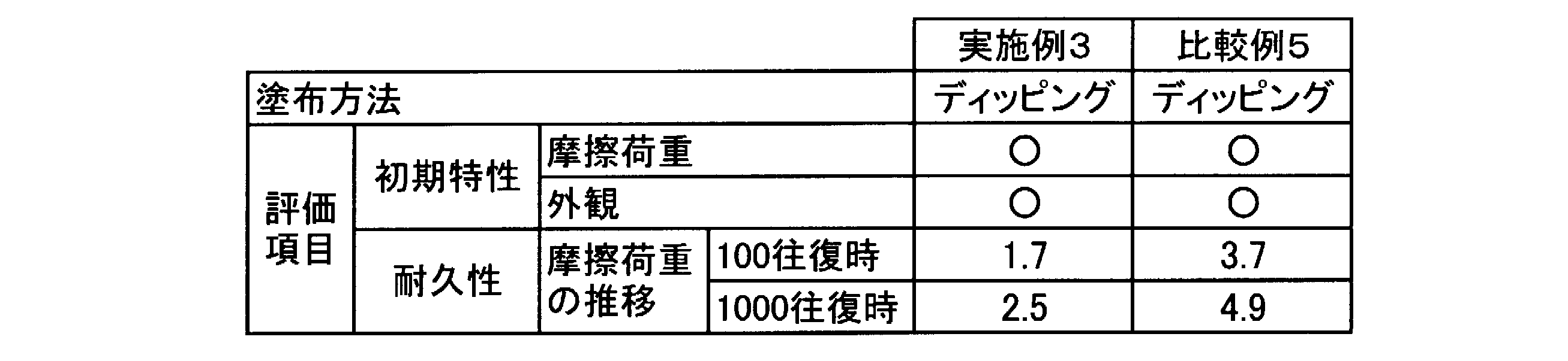

2a 第1ブジー
2b 第2ブジー
3 マーク
4 中央部
5a 第1筒状部
5b 第2筒状部
6 第1末端
7 ブジー挿入用の切れ目
8 第2末端
21 上涙点
22 下涙点
23 上涙小管
24 下涙小管
25 総涙小管
26 涙嚢
27 鼻涙管
28 下鼻道
30 オクリュージョンカテーテル
31 内管
32 外管
33 バルーン
34 ハブ
35 バルーン用ルーメン
36 内腔部
37 内層
38 外層
39 基材
40 コーティング層
41 第1開口部
42 第2開口部
43 内腔部
DESCRIPTION OF
Claims (13)
- 生体内へ挿入される挿入部材の表面に、下記(a)、(b)、(c1)を含有する組成物からなる中間層と、下記(a)、(b)、(c2)を含有する組成物からなる潤滑層とが順次積層された医療用チューブ;
(a)芳香族ジイソシアネート、脂肪族ジイソシアネート、および脂環族ジイソシアネートの少なくとも1種1~35重量%、
(b)3官能以上のポリオール1~35重量%、
(c1)ポリアルキレングリコール及び/又はモノメトキシポリアルキレングリコール30~98重量%、
(c2)ポリアルキレングリコール(重量平均分子量が(c1)のポリアルキレングリコールよりも大きいものが含まれる)及び/又はモノメトキシポリアルキレングリコール(重量平均分子量が(c1)のモノメトキシポリアルキレングリコールよりも大きいものが含まれる)30~98重量%、
(但し、(c1)、(c2)に関し、各グリコールはジオールである。)。 An intermediate layer made of a composition containing the following (a), (b), (c1) and the following (a), (b), (c2) are contained on the surface of the insertion member inserted into the living body. A medical tube in which a lubricating layer made of the composition is sequentially laminated;
(A) 1 to 35% by weight of at least one of aromatic diisocyanate, aliphatic diisocyanate, and alicyclic diisocyanate,
(B) 1 to 35% by weight of a tri- or higher functional polyol,
(C1) 30 to 98% by weight of polyalkylene glycol and / or monomethoxy polyalkylene glycol,
(C2) polyalkylene glycol (including those having a weight average molecular weight larger than that of (c1) polyalkylene glycol) and / or monomethoxy polyalkylene glycol (weight average molecular weight of (c1) than monomethoxy polyalkylene glycol) 30 to 98% by weight)
(However, regarding (c1) and (c2), each glycol is a diol). - 前記(c2)の成分として、前記(c1)の成分が10~50重量%含まれる請求項1記載の医療用チューブ。 The medical tube according to claim 1, wherein the component (c1) is contained in an amount of 10 to 50% by weight as the component (c2).
- 前記(a)、(b)、(c1)の成分及び溶媒を含有する中間層用コーティング液、並びに、前記(a)、(b)、(c2)の成分及び溶媒を含有する潤滑層用コーティング液を塗布、乾燥させて得られる請求項1又は2記載の医療用チューブにおいて、前記中間層用コーティング液における(a)、(b)、(c1)の成分の合計濃度が、潤滑層用コーティング液における(a)、(b)、(c2)の成分の合計濃度以下である医療用チューブ。 An intermediate layer coating solution containing the components (a), (b), (c1) and a solvent, and a lubricating layer coating containing the components (a), (b), (c2) and a solvent. The medical tube according to claim 1 or 2, wherein the total concentration of the components (a), (b) and (c1) in the intermediate layer coating liquid is obtained by applying and drying the liquid. A medical tube having a concentration equal to or lower than the total concentration of the components (a), (b), and (c2) in the liquid.
- 前記中間層用コーティング液における(a)、(b)、(c1)の成分の合計濃度が0.1~10重量%であり、前記潤滑層用コーティング液における(a)、(b)、(c2)の成分の合計濃度が、1.0~10重量%である請求項3記載の医療用チューブ。 The total concentration of the components (a), (b), and (c1) in the intermediate layer coating solution is 0.1 to 10% by weight, and (a), (b), ( The medical tube according to claim 3, wherein the total concentration of the components of c2) is 1.0 to 10% by weight.
- 前記中間層の組成物が、前記(a)、(b)、(c1)の成分の少なくとも一部を反応させたプレポリマーを含有してなる、及び/又は、前記潤滑層の組成物が前記(a)、(b)、(c1)、(c2)の成分の少なくとも一部を反応させたプレポリマーを含有してなる請求項1~4の何れかに記載の医療用チューブ。 The composition of the intermediate layer contains a prepolymer obtained by reacting at least part of the components (a), (b) and (c1), and / or the composition of the lubricating layer The medical tube according to any one of claims 1 to 4, comprising a prepolymer obtained by reacting at least part of the components (a), (b), (c1), and (c2).
- 前記中間層の組成物が、前記(a)、(b)、(c1)の成分を反応させた反応生成物である、及び/又は、前記潤滑層の組成物が前記(a)、(b)、(c1)、(c2)の成分を反応させた反応生成物である請求項1~5の何れかに記載の医療用チューブ。 The composition of the intermediate layer is a reaction product obtained by reacting the components (a), (b), and (c1), and / or the composition of the lubricating layer is the above (a), (b The medical tube according to any one of claims 1 to 5, which is a reaction product obtained by reacting the components (c), (c1) and (c2).
- 前記挿入部材を構成する材質が、シリコーン樹脂、イソブチレン系ブロック共重合体、熱可塑性ポリウレタン系樹脂、ポリアミド系樹脂からなる群から選択された少なくとも1種を含む請求項1~6の何れかに記載の医療用チューブ。 The material constituting the insertion member includes at least one selected from the group consisting of a silicone resin, an isobutylene block copolymer, a thermoplastic polyurethane resin, and a polyamide resin. Medical tubes.
- 前記医療用チューブが、涙道内に挿入され、留置される涙道チューブである請求項1~7の何れかに記載の医療用チューブ。 The medical tube according to any one of claims 1 to 7, wherein the medical tube is a lacrimal passage tube that is inserted into and placed in the lacrimal passage.
- 前記挿入部材を構成する材質が、イソブチレン系ブロック共重合体を含有した熱可塑性ポリウレタン系樹脂を含む請求項8記載の医療用チューブ。 The medical tube according to claim 8, wherein the material constituting the insertion member includes a thermoplastic polyurethane resin containing an isobutylene block copolymer.
- 請求項1~9の何れかに記載の医療用チューブの製造方法であって、
前記(a)、(b)、(c1)の成分及び溶媒を含有する中間層用コーティング液を調製した後、該中間層用コーティング液を10~50重量%含むように前記(a)、(b)、(c2)の成分及び溶媒を含有する潤滑層用コーティング液を調製する工程を含む医療用チューブの製造方法。 A method for producing a medical tube according to any one of claims 1 to 9,
After preparing an intermediate layer coating solution containing the components (a), (b), and (c1) and a solvent, the intermediate layer coating solution is contained so as to contain 10 to 50% by weight. b) The manufacturing method of a medical tube including the process of preparing the coating liquid for lubricating layers containing the component and solvent of (c2). - 前記(a)、(b)、(c1)の成分及び溶媒を含有する中間層用コーティング液を前記挿入部材に塗布し、乾燥させた後、前記(a)、(b)、(c2)の成分の合計濃度が前記中間層用コーティング液の(a)、(b)、(c1)の成分の合計濃度以上である潤滑層用コーティング液を塗布し、乾燥させて、前記挿入部材の表面に中間層と潤滑層を順次積層する工程を含む、請求項10記載の医療用チューブの製造方法。 The intermediate layer coating solution containing the components (a), (b), and (c1) and the solvent is applied to the insertion member and dried, and then the above (a), (b), and (c2). Apply the lubricating layer coating solution whose total component concentration is equal to or higher than the total concentration of the components (a), (b), and (c1) of the intermediate layer coating solution, and dry the coating solution on the surface of the insertion member. The manufacturing method of the medical tube of Claim 10 including the process of laminating | stacking an intermediate | middle layer and a lubrication layer one by one.
- 前記中間層用コーティング液における(a)、(b)、(c1)の成分の合計濃度が0.1~10重量%であり、前記潤滑層用コーティング液における(a)、(b)、(c2)の成分の合計濃度が、1.0~10重量%である請求項11記載の医療用チューブの製造方法。 The total concentration of the components (a), (b), and (c1) in the intermediate layer coating solution is 0.1 to 10% by weight, and (a), (b), ( The method for producing a medical tube according to claim 11, wherein the total concentration of the components of c2) is 1.0 to 10% by weight.
- 前記中間層用コーティング液及び/又は前記潤滑層用コーティングを前記挿入部材に塗布する工程が、ディッピング、中間層用コーティング液及び/又は前記潤滑層用コーティングを含むスポンジによる塗布、中間層用コーティング液及び/又は前記潤滑層用コーティングを含む刷毛による塗布、又は、噴霧である請求項10~12の何れかに記載のチューブの製造方法。
The step of applying the intermediate layer coating liquid and / or the lubricating layer coating to the insertion member includes dipping, applying with a sponge containing the intermediate layer coating liquid and / or the lubricating layer coating, and the intermediate layer coating liquid. The method for producing a tube according to any one of claims 10 to 12, wherein the tube is applied by a brush including the lubricating layer coating or sprayed.
Priority Applications (5)
| Application Number | Priority Date | Filing Date | Title |
|---|---|---|---|
| CN201380006802.7A CN104080490B (en) | 2012-01-26 | 2013-01-25 | Medical pipe |
| KR1020147023334A KR102059212B1 (en) | 2012-01-26 | 2013-01-25 | Medical tube |
| JP2013555317A JP6079642B2 (en) | 2012-01-26 | 2013-01-25 | Medical tube |
| US14/374,623 US10413701B2 (en) | 2012-01-26 | 2013-01-25 | Medical tube |
| EP13740721.9A EP2808041B1 (en) | 2012-01-26 | 2013-01-25 | Medical tube |
Applications Claiming Priority (2)
| Application Number | Priority Date | Filing Date | Title |
|---|---|---|---|
| JP2012-014592 | 2012-01-26 | ||
| JP2012014592 | 2012-01-26 |
Publications (1)
| Publication Number | Publication Date |
|---|---|
| WO2013111848A1 true WO2013111848A1 (en) | 2013-08-01 |
Family
ID=48873560
Family Applications (1)
| Application Number | Title | Priority Date | Filing Date |
|---|---|---|---|
| PCT/JP2013/051561 WO2013111848A1 (en) | 2012-01-26 | 2013-01-25 | Medical tube |
Country Status (6)
| Country | Link |
|---|---|
| US (1) | US10413701B2 (en) |
| EP (1) | EP2808041B1 (en) |
| JP (1) | JP6079642B2 (en) |
| KR (1) | KR102059212B1 (en) |
| CN (1) | CN104080490B (en) |
| WO (1) | WO2013111848A1 (en) |
Cited By (2)
| Publication number | Priority date | Publication date | Assignee | Title |
|---|---|---|---|---|
| WO2014034367A1 (en) * | 2012-08-31 | 2014-03-06 | 株式会社カネカ | Lacrimal duct tube |
| WO2015111553A1 (en) * | 2014-01-22 | 2015-07-30 | 株式会社カネカ | Lacrimal tube |
Families Citing this family (5)
| Publication number | Priority date | Publication date | Assignee | Title |
|---|---|---|---|---|
| CN104469945B (en) * | 2013-09-12 | 2019-01-25 | 索尼公司 | Activated control and method, the management method and base station apparatus of NCT SCC |
| US20150094609A1 (en) * | 2013-10-01 | 2015-04-02 | Alan L. Jacobson | Methods and systems for a self-retaining nasal dilator |
| US10674405B2 (en) * | 2014-02-21 | 2020-06-02 | Apple Inc. | System and method for throttling carrier aggregation activation |
| CN109288622B (en) * | 2018-11-02 | 2021-04-06 | 广州悦清再生医学科技有限公司 | Catheter with tissue protective mantle, preparation method and application |
| CN113116595B (en) * | 2019-12-30 | 2022-06-21 | 元心科技(深圳)有限公司 | Absorbable iron-based instrument |
Citations (9)
| Publication number | Priority date | Publication date | Assignee | Title |
|---|---|---|---|---|
| JPH04227671A (en) * | 1990-04-23 | 1992-08-17 | C R Bard Inc | Flexible and smooth organic coating film |
| JP2539325B2 (en) | 1992-11-12 | 1996-10-02 | 有限会社エム・エル・シー | Lacrimal intubation device |
| JPH11506375A (en) * | 1995-06-03 | 1999-06-08 | ワトソン ジェレミー | Lubricious coating |
| JP2001104485A (en) | 1999-10-04 | 2001-04-17 | Buaayu:Kk | Occlusion catheter for aorta ascendens |
| WO2006095766A1 (en) * | 2005-03-11 | 2006-09-14 | Kaneka Corporation | Wet lubricant surface coating having excellent durability, method for surface coating, and a medical device having the surface coating |
| WO2008023696A1 (en) * | 2006-08-21 | 2008-02-28 | Kaneka Corporation | Balloon catheter |
| WO2008156132A1 (en) | 2007-06-21 | 2008-12-24 | Kaneka Corporation | Surface coating composition having excellent durability which is lubricative in wet state, coating liquid, surface coating film, surface coating method, and medical device having the surface coating film |
| JP2010246857A (en) * | 2009-04-20 | 2010-11-04 | Kaneka Corp | Stent delivery system |
| JP2011200601A (en) | 2010-03-26 | 2011-10-13 | Kaneka Corp | Lacrimal duct tube |
Family Cites Families (1)
| Publication number | Priority date | Publication date | Assignee | Title |
|---|---|---|---|---|
| JP2539325Y2 (en) | 1988-03-31 | 1997-06-25 | 三菱自動車工業株式会社 | Lock brake device for vehicles |
-
2013
- 2013-01-25 JP JP2013555317A patent/JP6079642B2/en active Active
- 2013-01-25 CN CN201380006802.7A patent/CN104080490B/en active Active
- 2013-01-25 WO PCT/JP2013/051561 patent/WO2013111848A1/en active Application Filing
- 2013-01-25 US US14/374,623 patent/US10413701B2/en active Active
- 2013-01-25 EP EP13740721.9A patent/EP2808041B1/en active Active
- 2013-01-25 KR KR1020147023334A patent/KR102059212B1/en active IP Right Grant
Patent Citations (9)
| Publication number | Priority date | Publication date | Assignee | Title |
|---|---|---|---|---|
| JPH04227671A (en) * | 1990-04-23 | 1992-08-17 | C R Bard Inc | Flexible and smooth organic coating film |
| JP2539325B2 (en) | 1992-11-12 | 1996-10-02 | 有限会社エム・エル・シー | Lacrimal intubation device |
| JPH11506375A (en) * | 1995-06-03 | 1999-06-08 | ワトソン ジェレミー | Lubricious coating |
| JP2001104485A (en) | 1999-10-04 | 2001-04-17 | Buaayu:Kk | Occlusion catheter for aorta ascendens |
| WO2006095766A1 (en) * | 2005-03-11 | 2006-09-14 | Kaneka Corporation | Wet lubricant surface coating having excellent durability, method for surface coating, and a medical device having the surface coating |
| WO2008023696A1 (en) * | 2006-08-21 | 2008-02-28 | Kaneka Corporation | Balloon catheter |
| WO2008156132A1 (en) | 2007-06-21 | 2008-12-24 | Kaneka Corporation | Surface coating composition having excellent durability which is lubricative in wet state, coating liquid, surface coating film, surface coating method, and medical device having the surface coating film |
| JP2010246857A (en) * | 2009-04-20 | 2010-11-04 | Kaneka Corp | Stent delivery system |
| JP2011200601A (en) | 2010-03-26 | 2011-10-13 | Kaneka Corp | Lacrimal duct tube |
Non-Patent Citations (2)
| Title |
|---|
| HIROO YABE ET AL.: "The Effectiveness and Clinical Applications of a Hydrophilic Heparinized Polyurethane Lacrimal Stent Tube", JOURNAL OF OPHTHALMIC SURGERY, vol. 21, 2008, pages 237 - 242 |
| See also references of EP2808041A4 * |
Cited By (5)
| Publication number | Priority date | Publication date | Assignee | Title |
|---|---|---|---|---|
| WO2014034367A1 (en) * | 2012-08-31 | 2014-03-06 | 株式会社カネカ | Lacrimal duct tube |
| US9913753B2 (en) | 2012-08-31 | 2018-03-13 | Kaneka Corporation | Lacrimal duct tube |
| WO2015111553A1 (en) * | 2014-01-22 | 2015-07-30 | 株式会社カネカ | Lacrimal tube |
| JPWO2015111553A1 (en) * | 2014-01-22 | 2017-03-23 | 株式会社カネカ | Lacrimal tube |
| US10828194B2 (en) | 2014-01-22 | 2020-11-10 | Kaneka Corporation | Lacrimal duct tube |
Also Published As
| Publication number | Publication date |
|---|---|
| CN104080490B (en) | 2015-12-30 |
| EP2808041B1 (en) | 2016-08-24 |
| KR20140121852A (en) | 2014-10-16 |
| CN104080490A (en) | 2014-10-01 |
| EP2808041A4 (en) | 2015-09-02 |
| EP2808041A1 (en) | 2014-12-03 |
| JP6079642B2 (en) | 2017-02-15 |
| US20150018962A1 (en) | 2015-01-15 |
| US10413701B2 (en) | 2019-09-17 |
| JPWO2013111848A1 (en) | 2015-05-11 |
| KR102059212B1 (en) | 2019-12-24 |
Similar Documents
| Publication | Publication Date | Title |
|---|---|---|
| JP6079642B2 (en) | Medical tube | |
| EP3061469B1 (en) | Multilayer medical balloon | |
| JP5389063B2 (en) | Self-sealing PTFE graft with torsion resistance | |
| JP6031608B2 (en) | Guide extension catheter and guide extension catheter system | |
| EP1301235B1 (en) | Medical device with braid and coil | |
| EP1824551B1 (en) | Catheter having an ultra soft tip | |
| JP2015525636A (en) | Expandable guide extension catheter | |
| JP2009501062A (en) | Medical device balloon | |
| JP2001516621A (en) | Polyether block amide catheter balloon | |
| JPH04221571A (en) | Catheter tube with in vivo softening property controlled | |
| CA2924824C (en) | High pressure tear resistant balloon | |
| WO2001045784A1 (en) | High pressure catheter balloon | |
| AU2001273446A1 (en) | Medical device with braid and coil | |
| WO2008027401A2 (en) | Low friction particulate coatings | |
| WO2021068421A1 (en) | Special catheter for thrombus aspiration from distal cerebral vessel | |
| US7273471B1 (en) | Catheter balloon having a porous layer with ridges | |
| US20110022030A1 (en) | Fluorinated polymers in medical devices | |
| CN107184296B (en) | Sacculus, bracket conveyer and stent delivery system | |
| US10010344B2 (en) | Self-dilating catheter introducer with obturator and method of use | |
| WO2000062709A1 (en) | Delivery system for balloon expandable stent | |
| US20100268263A1 (en) | Embolic protection filters, filter membranes, and methods for making and using the same | |
| CN216571148U (en) | Bifurcated medicine balloon | |
| CN117959050A (en) | Recoverable spiral sacculus support | |
| JP2024503715A (en) | expandable sheath | |
| WO2024020566A2 (en) | Balloon delivery system for the implant deployment |
Legal Events
| Date | Code | Title | Description |
|---|---|---|---|
| 121 | Ep: the epo has been informed by wipo that ep was designated in this application |
Ref document number: 13740721 Country of ref document: EP Kind code of ref document: A1 |
|
| ENP | Entry into the national phase |
Ref document number: 2013555317 Country of ref document: JP Kind code of ref document: A |
|
| WWE | Wipo information: entry into national phase |
Ref document number: 14374623 Country of ref document: US |
|
| NENP | Non-entry into the national phase |
Ref country code: DE |
|
| REEP | Request for entry into the european phase |
Ref document number: 2013740721 Country of ref document: EP |
|
| WWE | Wipo information: entry into national phase |
Ref document number: 2013740721 Country of ref document: EP |
|
| ENP | Entry into the national phase |
Ref document number: 20147023334 Country of ref document: KR Kind code of ref document: A |