WO2013108864A1 - Disposable absorbent article - Google Patents
Disposable absorbent article Download PDFInfo
- Publication number
- WO2013108864A1 WO2013108864A1 PCT/JP2013/050889 JP2013050889W WO2013108864A1 WO 2013108864 A1 WO2013108864 A1 WO 2013108864A1 JP 2013050889 W JP2013050889 W JP 2013050889W WO 2013108864 A1 WO2013108864 A1 WO 2013108864A1
- Authority
- WO
- WIPO (PCT)
- Prior art keywords
- compression
- absorbent article
- surface side
- region
- compression recess
- Prior art date
Links
Images


Classifications
-
- A—HUMAN NECESSITIES
- A61—MEDICAL OR VETERINARY SCIENCE; HYGIENE
- A61F—FILTERS IMPLANTABLE INTO BLOOD VESSELS; PROSTHESES; DEVICES PROVIDING PATENCY TO, OR PREVENTING COLLAPSING OF, TUBULAR STRUCTURES OF THE BODY, e.g. STENTS; ORTHOPAEDIC, NURSING OR CONTRACEPTIVE DEVICES; FOMENTATION; TREATMENT OR PROTECTION OF EYES OR EARS; BANDAGES, DRESSINGS OR ABSORBENT PADS; FIRST-AID KITS
- A61F13/00—Bandages or dressings; Absorbent pads
- A61F13/15—Absorbent pads, e.g. sanitary towels, swabs or tampons for external or internal application to the body; Supporting or fastening means therefor; Tampon applicators
- A61F13/45—Absorbent pads, e.g. sanitary towels, swabs or tampons for external or internal application to the body; Supporting or fastening means therefor; Tampon applicators characterised by the shape
- A61F13/47—Sanitary towels, incontinence pads or napkins
- A61F13/475—Sanitary towels, incontinence pads or napkins characterised by edge leakage prevention means
- A61F13/4751—Sanitary towels, incontinence pads or napkins characterised by edge leakage prevention means the means preventing fluid flow in a transversal direction
- A61F13/4756—Sanitary towels, incontinence pads or napkins characterised by edge leakage prevention means the means preventing fluid flow in a transversal direction the means consisting of grooves, e.g. channels, depressions or embossments, resulting in a heterogeneous surface level
-
- A—HUMAN NECESSITIES
- A61—MEDICAL OR VETERINARY SCIENCE; HYGIENE
- A61F—FILTERS IMPLANTABLE INTO BLOOD VESSELS; PROSTHESES; DEVICES PROVIDING PATENCY TO, OR PREVENTING COLLAPSING OF, TUBULAR STRUCTURES OF THE BODY, e.g. STENTS; ORTHOPAEDIC, NURSING OR CONTRACEPTIVE DEVICES; FOMENTATION; TREATMENT OR PROTECTION OF EYES OR EARS; BANDAGES, DRESSINGS OR ABSORBENT PADS; FIRST-AID KITS
- A61F13/00—Bandages or dressings; Absorbent pads
- A61F13/15—Absorbent pads, e.g. sanitary towels, swabs or tampons for external or internal application to the body; Supporting or fastening means therefor; Tampon applicators
- A61F13/53—Absorbent pads, e.g. sanitary towels, swabs or tampons for external or internal application to the body; Supporting or fastening means therefor; Tampon applicators characterised by the absorbing medium
- A61F13/534—Absorbent pads, e.g. sanitary towels, swabs or tampons for external or internal application to the body; Supporting or fastening means therefor; Tampon applicators characterised by the absorbing medium having an inhomogeneous composition through the thickness of the pad
- A61F13/537—Absorbent pads, e.g. sanitary towels, swabs or tampons for external or internal application to the body; Supporting or fastening means therefor; Tampon applicators characterised by the absorbing medium having an inhomogeneous composition through the thickness of the pad characterised by a layer facilitating or inhibiting flow in one direction or plane, e.g. a wicking layer
- A61F13/53708—Absorbent pads, e.g. sanitary towels, swabs or tampons for external or internal application to the body; Supporting or fastening means therefor; Tampon applicators characterised by the absorbing medium having an inhomogeneous composition through the thickness of the pad characterised by a layer facilitating or inhibiting flow in one direction or plane, e.g. a wicking layer the layer having a promotional function on liquid propagation in at least one direction
- A61F13/53713—Absorbent pads, e.g. sanitary towels, swabs or tampons for external or internal application to the body; Supporting or fastening means therefor; Tampon applicators characterised by the absorbing medium having an inhomogeneous composition through the thickness of the pad characterised by a layer facilitating or inhibiting flow in one direction or plane, e.g. a wicking layer the layer having a promotional function on liquid propagation in at least one direction the layer having a promotional function on liquid propagation in the vertical direction
-
- A—HUMAN NECESSITIES
- A61—MEDICAL OR VETERINARY SCIENCE; HYGIENE
- A61F—FILTERS IMPLANTABLE INTO BLOOD VESSELS; PROSTHESES; DEVICES PROVIDING PATENCY TO, OR PREVENTING COLLAPSING OF, TUBULAR STRUCTURES OF THE BODY, e.g. STENTS; ORTHOPAEDIC, NURSING OR CONTRACEPTIVE DEVICES; FOMENTATION; TREATMENT OR PROTECTION OF EYES OR EARS; BANDAGES, DRESSINGS OR ABSORBENT PADS; FIRST-AID KITS
- A61F13/00—Bandages or dressings; Absorbent pads
- A61F13/15—Absorbent pads, e.g. sanitary towels, swabs or tampons for external or internal application to the body; Supporting or fastening means therefor; Tampon applicators
- A61F13/15577—Apparatus or processes for manufacturing
- A61F13/15617—Making absorbent pads from fibres or pulverulent material with or without treatment of the fibres
- A61F13/15658—Forming continuous, e.g. composite, fibrous webs, e.g. involving the application of pulverulent material on parts thereof
-
- A—HUMAN NECESSITIES
- A61—MEDICAL OR VETERINARY SCIENCE; HYGIENE
- A61F—FILTERS IMPLANTABLE INTO BLOOD VESSELS; PROSTHESES; DEVICES PROVIDING PATENCY TO, OR PREVENTING COLLAPSING OF, TUBULAR STRUCTURES OF THE BODY, e.g. STENTS; ORTHOPAEDIC, NURSING OR CONTRACEPTIVE DEVICES; FOMENTATION; TREATMENT OR PROTECTION OF EYES OR EARS; BANDAGES, DRESSINGS OR ABSORBENT PADS; FIRST-AID KITS
- A61F13/00—Bandages or dressings; Absorbent pads
- A61F13/15—Absorbent pads, e.g. sanitary towels, swabs or tampons for external or internal application to the body; Supporting or fastening means therefor; Tampon applicators
- A61F13/15577—Apparatus or processes for manufacturing
- A61F13/15707—Mechanical treatment, e.g. notching, twisting, compressing, shaping
-
- A—HUMAN NECESSITIES
- A61—MEDICAL OR VETERINARY SCIENCE; HYGIENE
- A61F—FILTERS IMPLANTABLE INTO BLOOD VESSELS; PROSTHESES; DEVICES PROVIDING PATENCY TO, OR PREVENTING COLLAPSING OF, TUBULAR STRUCTURES OF THE BODY, e.g. STENTS; ORTHOPAEDIC, NURSING OR CONTRACEPTIVE DEVICES; FOMENTATION; TREATMENT OR PROTECTION OF EYES OR EARS; BANDAGES, DRESSINGS OR ABSORBENT PADS; FIRST-AID KITS
- A61F13/00—Bandages or dressings; Absorbent pads
- A61F13/15—Absorbent pads, e.g. sanitary towels, swabs or tampons for external or internal application to the body; Supporting or fastening means therefor; Tampon applicators
- A61F13/45—Absorbent pads, e.g. sanitary towels, swabs or tampons for external or internal application to the body; Supporting or fastening means therefor; Tampon applicators characterised by the shape
- A61F13/47—Sanitary towels, incontinence pads or napkins
- A61F13/4704—Sanitary towels, incontinence pads or napkins having preferential bending zones, e.g. fold lines or grooves
-
- A—HUMAN NECESSITIES
- A61—MEDICAL OR VETERINARY SCIENCE; HYGIENE
- A61F—FILTERS IMPLANTABLE INTO BLOOD VESSELS; PROSTHESES; DEVICES PROVIDING PATENCY TO, OR PREVENTING COLLAPSING OF, TUBULAR STRUCTURES OF THE BODY, e.g. STENTS; ORTHOPAEDIC, NURSING OR CONTRACEPTIVE DEVICES; FOMENTATION; TREATMENT OR PROTECTION OF EYES OR EARS; BANDAGES, DRESSINGS OR ABSORBENT PADS; FIRST-AID KITS
- A61F13/00—Bandages or dressings; Absorbent pads
- A61F13/15—Absorbent pads, e.g. sanitary towels, swabs or tampons for external or internal application to the body; Supporting or fastening means therefor; Tampon applicators
- A61F13/53—Absorbent pads, e.g. sanitary towels, swabs or tampons for external or internal application to the body; Supporting or fastening means therefor; Tampon applicators characterised by the absorbing medium
- A61F13/534—Absorbent pads, e.g. sanitary towels, swabs or tampons for external or internal application to the body; Supporting or fastening means therefor; Tampon applicators characterised by the absorbing medium having an inhomogeneous composition through the thickness of the pad
- A61F13/537—Absorbent pads, e.g. sanitary towels, swabs or tampons for external or internal application to the body; Supporting or fastening means therefor; Tampon applicators characterised by the absorbing medium having an inhomogeneous composition through the thickness of the pad characterised by a layer facilitating or inhibiting flow in one direction or plane, e.g. a wicking layer
- A61F13/53743—Absorbent pads, e.g. sanitary towels, swabs or tampons for external or internal application to the body; Supporting or fastening means therefor; Tampon applicators characterised by the absorbing medium having an inhomogeneous composition through the thickness of the pad characterised by a layer facilitating or inhibiting flow in one direction or plane, e.g. a wicking layer characterised by the position of the layer relative to the other layers
- A61F13/53747—Absorbent pads, e.g. sanitary towels, swabs or tampons for external or internal application to the body; Supporting or fastening means therefor; Tampon applicators characterised by the absorbing medium having an inhomogeneous composition through the thickness of the pad characterised by a layer facilitating or inhibiting flow in one direction or plane, e.g. a wicking layer characterised by the position of the layer relative to the other layers the layer is facing the topsheet
-
- A—HUMAN NECESSITIES
- A61—MEDICAL OR VETERINARY SCIENCE; HYGIENE
- A61F—FILTERS IMPLANTABLE INTO BLOOD VESSELS; PROSTHESES; DEVICES PROVIDING PATENCY TO, OR PREVENTING COLLAPSING OF, TUBULAR STRUCTURES OF THE BODY, e.g. STENTS; ORTHOPAEDIC, NURSING OR CONTRACEPTIVE DEVICES; FOMENTATION; TREATMENT OR PROTECTION OF EYES OR EARS; BANDAGES, DRESSINGS OR ABSORBENT PADS; FIRST-AID KITS
- A61F13/00—Bandages or dressings; Absorbent pads
- A61F13/15—Absorbent pads, e.g. sanitary towels, swabs or tampons for external or internal application to the body; Supporting or fastening means therefor; Tampon applicators
- A61F13/53—Absorbent pads, e.g. sanitary towels, swabs or tampons for external or internal application to the body; Supporting or fastening means therefor; Tampon applicators characterised by the absorbing medium
- A61F13/534—Absorbent pads, e.g. sanitary towels, swabs or tampons for external or internal application to the body; Supporting or fastening means therefor; Tampon applicators characterised by the absorbing medium having an inhomogeneous composition through the thickness of the pad
- A61F13/537—Absorbent pads, e.g. sanitary towels, swabs or tampons for external or internal application to the body; Supporting or fastening means therefor; Tampon applicators characterised by the absorbing medium having an inhomogeneous composition through the thickness of the pad characterised by a layer facilitating or inhibiting flow in one direction or plane, e.g. a wicking layer
- A61F13/53743—Absorbent pads, e.g. sanitary towels, swabs or tampons for external or internal application to the body; Supporting or fastening means therefor; Tampon applicators characterised by the absorbing medium having an inhomogeneous composition through the thickness of the pad characterised by a layer facilitating or inhibiting flow in one direction or plane, e.g. a wicking layer characterised by the position of the layer relative to the other layers
- A61F13/53756—Absorbent pads, e.g. sanitary towels, swabs or tampons for external or internal application to the body; Supporting or fastening means therefor; Tampon applicators characterised by the absorbing medium having an inhomogeneous composition through the thickness of the pad characterised by a layer facilitating or inhibiting flow in one direction or plane, e.g. a wicking layer characterised by the position of the layer relative to the other layers the layer facing the back-sheet
-
- A—HUMAN NECESSITIES
- A61—MEDICAL OR VETERINARY SCIENCE; HYGIENE
- A61F—FILTERS IMPLANTABLE INTO BLOOD VESSELS; PROSTHESES; DEVICES PROVIDING PATENCY TO, OR PREVENTING COLLAPSING OF, TUBULAR STRUCTURES OF THE BODY, e.g. STENTS; ORTHOPAEDIC, NURSING OR CONTRACEPTIVE DEVICES; FOMENTATION; TREATMENT OR PROTECTION OF EYES OR EARS; BANDAGES, DRESSINGS OR ABSORBENT PADS; FIRST-AID KITS
- A61F13/00—Bandages or dressings; Absorbent pads
- A61F13/15—Absorbent pads, e.g. sanitary towels, swabs or tampons for external or internal application to the body; Supporting or fastening means therefor; Tampon applicators
- A61F13/53—Absorbent pads, e.g. sanitary towels, swabs or tampons for external or internal application to the body; Supporting or fastening means therefor; Tampon applicators characterised by the absorbing medium
- A61F2013/530007—Absorbent pads, e.g. sanitary towels, swabs or tampons for external or internal application to the body; Supporting or fastening means therefor; Tampon applicators characterised by the absorbing medium being made from pulp
-
- A—HUMAN NECESSITIES
- A61—MEDICAL OR VETERINARY SCIENCE; HYGIENE
- A61F—FILTERS IMPLANTABLE INTO BLOOD VESSELS; PROSTHESES; DEVICES PROVIDING PATENCY TO, OR PREVENTING COLLAPSING OF, TUBULAR STRUCTURES OF THE BODY, e.g. STENTS; ORTHOPAEDIC, NURSING OR CONTRACEPTIVE DEVICES; FOMENTATION; TREATMENT OR PROTECTION OF EYES OR EARS; BANDAGES, DRESSINGS OR ABSORBENT PADS; FIRST-AID KITS
- A61F13/00—Bandages or dressings; Absorbent pads
- A61F13/15—Absorbent pads, e.g. sanitary towels, swabs or tampons for external or internal application to the body; Supporting or fastening means therefor; Tampon applicators
- A61F13/53—Absorbent pads, e.g. sanitary towels, swabs or tampons for external or internal application to the body; Supporting or fastening means therefor; Tampon applicators characterised by the absorbing medium
- A61F2013/530481—Absorbent pads, e.g. sanitary towels, swabs or tampons for external or internal application to the body; Supporting or fastening means therefor; Tampon applicators characterised by the absorbing medium having superabsorbent materials, i.e. highly absorbent polymer gel materials
- A61F2013/53051—Absorbent pads, e.g. sanitary towels, swabs or tampons for external or internal application to the body; Supporting or fastening means therefor; Tampon applicators characterised by the absorbing medium having superabsorbent materials, i.e. highly absorbent polymer gel materials being only in particular parts or specially arranged
- A61F2013/530547—Absorbent pads, e.g. sanitary towels, swabs or tampons for external or internal application to the body; Supporting or fastening means therefor; Tampon applicators characterised by the absorbing medium having superabsorbent materials, i.e. highly absorbent polymer gel materials being only in particular parts or specially arranged positioned in a separate layer or layers
-
- A—HUMAN NECESSITIES
- A61—MEDICAL OR VETERINARY SCIENCE; HYGIENE
- A61F—FILTERS IMPLANTABLE INTO BLOOD VESSELS; PROSTHESES; DEVICES PROVIDING PATENCY TO, OR PREVENTING COLLAPSING OF, TUBULAR STRUCTURES OF THE BODY, e.g. STENTS; ORTHOPAEDIC, NURSING OR CONTRACEPTIVE DEVICES; FOMENTATION; TREATMENT OR PROTECTION OF EYES OR EARS; BANDAGES, DRESSINGS OR ABSORBENT PADS; FIRST-AID KITS
- A61F13/00—Bandages or dressings; Absorbent pads
- A61F13/15—Absorbent pads, e.g. sanitary towels, swabs or tampons for external or internal application to the body; Supporting or fastening means therefor; Tampon applicators
- A61F13/53—Absorbent pads, e.g. sanitary towels, swabs or tampons for external or internal application to the body; Supporting or fastening means therefor; Tampon applicators characterised by the absorbing medium
- A61F13/534—Absorbent pads, e.g. sanitary towels, swabs or tampons for external or internal application to the body; Supporting or fastening means therefor; Tampon applicators characterised by the absorbing medium having an inhomogeneous composition through the thickness of the pad
- A61F13/537—Absorbent pads, e.g. sanitary towels, swabs or tampons for external or internal application to the body; Supporting or fastening means therefor; Tampon applicators characterised by the absorbing medium having an inhomogeneous composition through the thickness of the pad characterised by a layer facilitating or inhibiting flow in one direction or plane, e.g. a wicking layer
- A61F2013/53765—Absorbent pads, e.g. sanitary towels, swabs or tampons for external or internal application to the body; Supporting or fastening means therefor; Tampon applicators characterised by the absorbing medium having an inhomogeneous composition through the thickness of the pad characterised by a layer facilitating or inhibiting flow in one direction or plane, e.g. a wicking layer characterized by its geometry
Definitions
- This invention relates to disposable absorbent articles such as sanitary napkins, incontinence pads, urine absorbing pads, panty liners and the like.
- Patent Document 1 includes a liquid-permeable top sheet, a liquid-impervious back sheet, and an absorbent layer interposed between these sheets.
- an absorbent article in which a line-shaped compression recess is formed in each of the compression recess and the absorbent layer, and these compression recesses overlap each other in the thickness direction.
- the compression recess of the top sheet and the compression recess of the absorbent layer overlap each other on the surface side, the compression region becomes relatively high in rigidity, and the flexibility on the surface side may be lowered.
- a compression recess is attached to the top sheet from the surface side so as to overlap with the compression recess positioned on the surface side of the absorbent layer, pressure is concentrated on the compression recess, and in the manufacturing process, the top sheet and There is a possibility that a part of the absorption layer is broken and a part of the superabsorbent polymer particles contained in the absorption layer falls off to the outside.
- An object of the present invention is to improve a conventional absorbent article, and provide a disposable absorbent article capable of ensuring flexibility and at least partially forming a thin film without reducing liquid absorption. There is to do.
- the present invention has a vertical direction, a horizontal direction, and a thickness direction, and has a front side and a back side, a liquid-permeable top sheet positioned on the front side, and the back side.
- the present invention relates to a disposable absorbent article that includes a liquid-impermeable back sheet positioned in the sheet and an absorbent layer interposed between the sheets.
- the feature of the present invention is that the first end region, the second end region spaced apart from the first end region in the longitudinal direction, the first end region, and the second end region.
- a plurality of second compression recesses that are recessed from the back surface side to the front surface side of the absorbent layer are disposed apart from each other in the vertical direction and the horizontal direction.
- a part of the compression recess and the part of the second compression recess are located opposite to each other.
- At least one of the first and second end regions is intermittent so that a part of the first compression recess and a part of the second compression recess overlap each other in the thickness direction. Therefore, the entire end region can be formed relatively thin while ensuring the required flexibility.
- FIG. 3 is a schematic longitudinal sectional view taken along line III-III in FIG. 1.
- FIG. 4 is a schematic cross-sectional view taken along line VI-VI in FIG. 1.
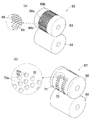
- C The elements on larger scale enclosed with the dashed-dotted line VIIC of FIG. Schematic of the manufacturing apparatus of a disposable absorbent article.
- A The expansion perspective view of the 1st embossing part of a manufacturing apparatus.
- B The expansion perspective view of the 2nd embossing part of a manufacturing apparatus.
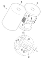
- A The expansion perspective view of the rotating drum of the SAP distribution part of a manufacturing apparatus.
- B The expansion perspective view of the heat seal part of a manufacturing apparatus.
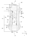
- the absorbent article 10 has a longitudinal direction Y and a transverse direction X, a thickness direction Z, a front surface (skin facing surface) side and a back surface (non-skin facing surface) side, a longitudinal axis P extending in parallel with the longitudinal direction Y, and It has a horizontal axis Q extending in parallel with the horizontal direction X, and is substantially symmetrical with respect to the vertical axis P and the horizontal axis Q.
- an absorbent article 10 includes first and second end edges 10a and 10b that are curved outward in the longitudinal direction Y, and both side edges 10c that are curved toward the vertical axis P. , 10d, a liquid-permeable top sheet 11 located on the front surface side, a back sheet 12 located on the back surface side, a liquid-absorbing absorbent layer 13 located between these sheets 11, 12, An intermediate sheet 14 positioned between the top sheet 11 and the absorbent layer 13 is included.
- the absorbent article 10 includes a central region 15, a first end region 16 located on the first end edge 10 a side from the central region 15, and a second end located on the second end edge 10 b side from the central region 15. It is divided into an end region 17.
- a pair of compressed grooves 18 that are spaced apart from each other in the lateral direction X and extend in the longitudinal direction Y and are concave in the thickness direction from the surface side are disposed.
- a plurality of first compression recesses 20 that are concave in the thickness direction from the surface side and are separated from each other in the vertical and horizontal directions Y and X are arranged.
- the first compression recess 20 has a substantially cross shape in a plan view, and is disposed in at least one of the first and second end regions 16, 17, preferably in the existence region of the absorption layer 13 in both.
- the top sheet 11 and the back sheet 12 extend outward from the peripheral edge of the absorbent layer 13 and are bonded to each other through appropriate joining means, for example, a hot melt adhesive.
- the back sheet 12 extends further outward in the lateral direction X than the top sheet 11, and a pair of side sheets 21 are joined on the skin facing surface.
- An end flap positioned outside the absorbent layer 13 in the longitudinal direction Y by a part of the top sheet 11, the back sheet 12 and the side sheet 21, and a side flap positioned outside the absorbent layer 13 in the lateral direction X are respectively provided. It is formed.
- a part of the outer peripheral edge of the end flap and a part of the outer peripheral edge of the side flap are sealed by hot embossing / debossing to form a seal portion 22.
- Each of the sheets 11, 12, 14, and 21 is joined by a hot melt adhesive (not shown) in addition to being joined by the fiber entanglement in the compressed groove 18 in the overlapping portion.
- the side seat 21 has a fixing part that forms a part of the side flap and the end flap, and a sleeve-like or loop-like distal edge that extends in the longitudinal direction between the end flaps, and at least one strip in the distal edge.
- the elastic elements 23 in the form of threads, threads, strings or strands are provided so as to be stretchable in the longitudinal direction Y.
- the side sheet 21 and the elastic element 23 form a containment cuff for suppressing body fluid from leaking out of the absorbent article 10.
- the top sheet 11 can be formed from various fiber nonwoven fabrics having liquid permeability, for example, an air-through fiber nonwoven fabric having a mass of about 20 to 40 g / m 2 , a porous plastic film, or a laminate sheet thereof.
- the back sheet 12 can be formed from a liquid-impervious and breathable plastic film, a hardly liquid-permeable fiber nonwoven fabric, or a laminate sheet thereof.
- the intermediate sheet 14 can be formed from various fiber nonwoven fabrics having air permeability and liquid permeability, for example, air-through nonwoven fabric having a mass of about 15 to 45 g / m 2 .
- the intermediate sheet 14 is optional, improves the cushioning property against the wearer's skin, does not diffuse the body fluid into the delirium, and separates the top sheet 11 and the absorbent layer 13 to make the body fluid top in the delirium. This prevents backflow to the sheet 11.
- the side sheet 21 is formed from a liquid-impervious SMS (spunbond / meltblown / spunbond) non-woven fabric, spunbond non-woven fabric, polyethylene plastic sheet or laminate sheet having a mass of about 10 to 30 g / m 2. Can do.
- the absorbent layer 13 has a two-layer structure composed of a first absorbent member (lower layer) 25 located on the back side and a second absorbent member (upper layer) 26 located on the front side.
- the 1st absorption member 25 forms the outline of the absorption layer 13 in which the center part extended from the center area
- the second absorbent member 26 has a substantially rectangular shape whose length in the longitudinal direction Y is smaller than that of the first absorbent member 25, and is located in the central region 15.
- the compressed groove 18 is disposed so as to overlap the second absorbent member 26.
- the central region 15 may be a bulky single layer structure or a multilayer structure of two or more layers, and a plurality of central regions 15 facing the wearer's excretion opening may be provided.
- the first absorbent member 25 is composed of discrete so-called superabsorbent polymer particles (SAP) having a mass of about 100 to 300 g / m 2 and having a water insolubility and a water absorption capacity of 10 times or more of the self mass.
- Liquid absorbent core 30 in which wood fluff pulp having a mass of about 200 to 400 g / m 2 and, optionally, 30% by mass or less thermoplastic synthetic fiber (staple fiber) is mixed and shaped into a predetermined shape, and its shape retention
- a core wrap sheet 31 that encapsulates the entire liquid-absorbent core for improving the property and liquid diffusibility.
- the core wrap sheet 31 includes a liquid-permeable first sheet 32 located on the front surface side and a liquid-permeable or hardly liquid-permeable second sheet 33 located on the back surface side.
- the 1st compression recessed part 20 is dented toward the back surface side from the surface side so that the top sheet 11, the intermediate sheet 14, and the absorption layer 13 may be compressed, as long as there exists an effect of this invention of a postscript, at least an absorption layer 13 may be recessed from the front surface side toward the back surface side, and may be recessed from the intermediate sheet 14 toward the absorption layer 13.
- the first absorbent member 25 includes an intermediate portion 34 located in the central region 15 of the absorbent article 10, a first end portion 35 located in the first end region 16, and a second end region 17. And a second end 36 located at the end.
- the first end portion 35 and the second end portion 36 have substantially the same size (area), and a plurality of second end portions that are concave in the thickness direction from the back surface side are formed on the entire back surface side of the first absorbent member 25.
- Two compression recesses 37 are arranged in the vertical direction Y and the horizontal direction X so as to be separated from each other.
- a plurality of third compression recesses 38 that are recessed in the thickness direction from the back surface side are disposed in the intermediate portion 34 so as to be separated from each other in the vertical direction Y and the horizontal direction X.
- the second compression recess 37 and the third compression recess 38 are arranged so that part of them overlaps each other.
- the second compression concave portion 37 has a horizontally long substantially elliptical shape extending in the direction of the horizontal axis Q so as to be orthogonal to the vertical axis P, and is relatively dense at the first and second end portions 35, 36.
- the intermediate portion 34 is relatively sparsely arranged.
- the third compression recess 38 has a substantially circular shape in plan view, and is formed in a tapered shape in which the width dimension gradually decreases toward the back surface side. 38a is located.
- the third compression concave portion 38 is disposed in a region excluding the central portion (non-compressed portion) 40 on the back surface side of the intermediate portion 34, and the central portion 40 is bulky as compared with other regions of the intermediate portion 34. ing.
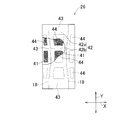
- the second absorbent member 26 includes discrete superabsorbent polymer particles 41 and a core wrap sheet 42 that encloses the superabsorbent polymer particles 41.
- the core wrap sheet 42 includes a first sheet 42a located on the front surface side and a second sheet 42b located on the back surface side.
- the second absorbent member 26 includes a seal region 43 formed by joining the sheets 42a and 42b to each other, and a liquid absorption region 44 surrounded by the seal region 43 and disposed with superabsorbent polymer particles. Is defined.
- the second absorbent member 26 does not contain wood fluff pulp and is formed by covering the superabsorbent polymer particles with the core wrap sheet 42, the second absorbent member 26 is thinner than the first absorbent member 25, and the second absorbent member 26 is thin in the central region 15. Even if the 1 absorption member 25 and the 2nd absorption member 26 are laminated
- the liquid absorption area 44 of the second absorption member 26 is divided into nine, and the compressed groove 18 (shown by phantom lines in FIG. 5) is arranged so as to overlap the seal area 43.
- region 44 is arrange
- the superabsorbent polymer particles When the superabsorbent polymer particles are dispersed in the liquid absorption area 44, the superabsorbent polymer particles may scatter in a small amount in the seal area 43 at the time of application, and the small quantity can be allowed as long as the sealing function of the seal area 43 is not hindered. Because. Similarly, a small amount of wood fluff pulp may be contained in the liquid absorption area 44 as long as the required effect is obtained. Moreover, the liquid absorption area
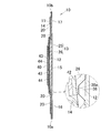
- the first compression recess 20 has a top sheet 11, an intermediate sheet 14, a second absorbent member 26 of the absorbent layer 13 and a second absorbent member 13 from the front surface side to the back surface side. 1 absorption member 25 is reached. Further, in the first and second end regions 16 and 17 of the absorbent article 10, a part of the first compression recess 20 and a part of the second compression recess 37 overlap each other in the thickness direction Z. The dimensions of the absorbent layer 13 will be described. The dimension of the first end region 16 of the absorbent layer 13 in the thickness direction Z (the same applies to the thickness of the second end region 17 in the thickness direction Z) W1 is about 2.5 to 4.
- FIG. 6 is a schematic cross-sectional view, and the compression shape of each compression recess 20 and 37 is represented by a substantially linear shape. And since a part of fiber compressed after embossing / debossing recovers in bulk, the cross section of each compression recessed part 20 and 37 becomes an irregular form instead of linear.
- the second compression recess 37 is disposed on the back surface side of the first absorbent member 25, so that the bulk recovery force works toward the front surface side, and the front surface side becomes bulky and attached. Since the first compression recess 20 is formed by compressing the top sheet 11, the intermediate sheet 14, and the second absorbent member 26 from the surface side in a state where the feeling may be impaired, the first absorbent member is formed. The bulkiness to the surface side of 25 is suppressed, and it can be set as desired thickness in the 1st and 2nd end regions 16 and 17 without impairing a wearing feeling.
- the absorbent article 10 when used as a sanitary napkin, it is packaged and sold in an individual packaging bag made of a plastic film from the viewpoint of hygiene, and is folded in two or three to be stored compactly in the packaging bag. Wrapped in a packed state.
- the first and second end regions 16 and 17 are thinner than conventional products while ensuring flexibility, the first and second end regions 16 and 17 and Even if the central region 15 is folded so that they overlap each other, it can be stored more compactly without being bulky.
- a plurality of second compression recesses 37 are relatively sparsely disposed throughout, and the region excluding the central portion 40 has a plurality of second compression recesses 37. Since the three compression recesses 38 are spaced apart from each other in the vertical direction Y and the horizontal direction X, the central portion 40 is bulky as compared with other regions. Therefore, the site
- the absorbent layer 13 of the present invention can be used for various absorbent articles such as sanitary napkins and incontinence pads.
- various absorbent articles such as sanitary napkins and incontinence pads.
- an incontinence pad for adults intended for elderly people in their late 50s to 70s it is necessary to absorb about 100 to 170 cc of body fluid with a single excretion.
- the thickness of the incontinence pad is increased from the wearing articles (especially on the abdomen and back side) such as underwear and clothes because the thickness becomes relatively large, especially after absorbing bodily fluids, the thickness of the absorbent layer increases. There was a problem that the appearance of the worn article was damaged by being raised.
- the absorbent layer 13 of the present invention When the absorbent layer 13 of the present invention is used for an incontinence pad for adults, the first and second end portions 35 and 36 are partially compressed from the front and back sides to ensure flexibility. Because it is relatively thin, the incontinence pad does not easily float on the outside of the stomach or back of clothing even after absorbing bodily fluids, and elderly people can wear it with peace of mind when they go out. it can.
- the first compression recess 20 has a longitudinal dimension Y of one side (the same dimension in the lateral direction X) L1 of about 3.0 to 5.0 mm, and between each first compression recess 20
- the separation dimension R1 is about 8.0 to 12.0 mm
- the area ratio of the first absorbing member 25 to the area of the first or second end 35 or 36 is about 1 to 10%.
- the first compression recesses 20 are spaced apart from each other in the vertical direction Y and the horizontal direction X, and an uncompressed region 49 is defined in a region surrounded by the first compression recesses 20.
- the first compression recess 20 has various known shapes such as a star pattern and a floral pattern, a trapezoid, a rhombus, and any other geometric shape as well as a cross shape as in the present embodiment. It may be.
- the compression part has a shape extending in a direction intersecting each other, such as a cross shape. In this case, since the pressure is distributed to the intersecting sides at the time of manufacturing, the fibers are not pulled in a certain direction, and there is no possibility that wrinkles that form body fluid flow paths are formed in a certain direction. is there.
- the dimension L2 of the second compression recess 37 in the lateral direction X is about 2.0 to 4.0 mm, and the separation dimension R2 between the second compression recesses 37 is about 0.5 to 1..
- the area ratio with respect to the area of the first and second end portions 35 and 36 of the first absorbent member is 0 to 50%, preferably 15 to 25%.
- the second compression recesses 37 are disposed relatively densely on the back surfaces of the first and second end portions 35 and 36 of the first absorbent member 25 than the first compression recesses 20 located on the front surface side.
- the second compression recesses 37 do not extend continuously in a fixed direction, but are disposed apart from each other in the vertical direction Y and the horizontal direction X.
- the second compression recess 37 may have various known shapes, but is preferably different in size and shape from the first compression recess 20.
- the thinnest portion 46 is formed in a relatively wide range when their positions coincide in the thickness direction Z. This is because the strength of the absorbent article 10 may be reduced.
- the third compression recess 38 has a diameter D1 of about 6.0 to 10.0 mm, and the separation dimension R3 in the longitudinal direction Y of each adjacent third compression recess 38 is 7. 0 to 11.0 mm.
- the area ratio of the entire third compression recess 38 with respect to the area of the intermediate portion 34 of the first absorbent member 25 is about 10 to 80%, preferably 40 to 60%.
- the third compression recess 38 partially overlaps the second compression recess 37.
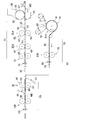
- the manufacturing apparatus 50 for the absorbent article 10 includes a first molding station 51 for molding the first absorbent member 25 described above and a first molding station 51 for molding the second absorbent member 26 described above. 2 includes a molding station 52 and an assembly station 53 for assembling the first absorbent member 25 and the second absorbent member 26 on top of each other.
- the absorbent article 10 is manufactured in an upside down manner (the surface side is positioned downward).
- the aspect of FIG. 8 and subsequent description show an example of the manufacturing apparatus and manufacturing method of the absorbent article 10, and have the same function. Other manufacturing apparatuses and manufacturing methods are not excluded.
- the liquid absorbent core 30 is supplied and laminated from the rotary drum 57 on the first carrier sheet 56 conveyed in the machine direction MD via the conveyor belt 55.
- a deposition recess 58 having a suction function substantially the same shape as the plurality of first absorbing members 25 is provided.
- a liquid absorbent core 30 shaped into a required form is formed by filling a liquid absorbent material obtained by mixing the supplied wood fluff pulp and loose superabsorbent polymer particles.
- the first carrier sheet 56 is conveyed under tension in the machine direction MD by a tension roll.
- the second carrier sheet 60 fed from the feeding roll is laminated on the upper surface, and the first and second carrier sheets 56, 60 are mutually connected with the absorbent core 30 interposed therebetween.
- the first absorbent web 61 is formed by being bonded to each other via a hot melt adhesive.
- the above-described second compression recess 37 is disposed on the upper surface. Is done. Referring to FIG.
- both rollers 63 and 64 are Heating at 80 to 95 degrees is preferable.
- the first absorbent web 61 is pressed at a second emboss / deboss portion 67 composed of an emboss / deboss roller 68 and a smooth roller 69.
- a press portion 71 including a plurality of dot-like protrusions 70 is formed on the outer peripheral surface of the emboss / deboss roller 68.
- a non-pressing part 72 where no projection 70 is arranged is defined, and a first absorbent property is provided between the embossing / debossing roller 68 and the smoothing roller 69 heated to about 80 to 90 degrees.
- the above-described third compression recess 38 is formed on the upper surface thereof.
- the protrusion 70 has a sub protrusion 70a at the center thereof.
- the flat core 73 formed of a pair of smooth rollers causes the liquid absorbent core 30 to lose its shape. Pressed to prevent.
- the first absorbent member 25 described above is formed by cutting the first absorbent web 61 along the outer shape of the liquid absorbent core 30 at the cut portion 74.
- the second molding station 52 includes a superabsorbent polymer particle (SAP, hereinafter the same) spreading unit 76, a heat seal unit 79, and a cut unit 80.
- SAP superabsorbent polymer particle
- the SAP spreading unit 76 includes a rotating drum 81 and a supply pipe 82 that supplies the superabsorbent polymer particles 41 to the rotating drum 81, and the third carrier sheet 77 fed from the feeding roll is an outer peripheral surface of the rotating drum 81. Supplied along. As shown in FIG. 10A, the outer peripheral surface of the rotating drum 81 is provided with a plurality of accumulation recesses 84 having a suction function surrounded by a lattice-like frame 83, and the third carrier sheet 77 serves as the rotating drum. After being supplied onto 81, the superabsorbent polymer particles 41 are dispersed on the third carrier sheet 77 from the supply pipe 82 to the deposition recesses 84.
- the fourth carrier sheet 78 supplied to the rotating drum 81 is laminated on the upper surface thereof to form the second absorbent web 85.
- a plurality of the accumulation recesses 84 of the rotating drum 81 are provided side by side in the circumferential direction of the rotating drum 81 and the width direction orthogonal thereto.
- the plurality of liquid-absorbing areas 44 described above and the above-described seal area 43 that is positioned corresponding to the frame 83 and is not substantially sprayed with the superabsorbent polymer particles 41 are formed.
- the second absorbent web 85 is conveyed to the heat seal part 79 composed of the heating roller 86 and the smooth roller 87.
- the outer peripheral surface of the heating roller 86 is provided with a lattice-like frame 89 and a plurality of recesses 88 surrounded by the same as the outer peripheral surface of the rotary drum 81, and the seal region 43 is hot-pressed by the frame 89 and sealed.
- the second absorbent web 85 described above is formed by cutting the second absorbent web 85 into a rectangular shape at the cut part 80.
- sheets serving as materials for the top sheet 11, the intermediate sheet 14, and the side sheets 21 are supplied to the second absorbent member 26 molded in the second molding station 52.
- the composite web 90 is formed by disposing the first absorbent member 25 on the surface.
- the composite web 90 is disposed on the transport belt 91 and transported in the machine direction MD, and emboss / deboss processing is performed on the lower surface at a third emboss / deboss portion 92 composed of an emboss / deboss roller 93 and a smooth roller 94.
- a central portion of the outer peripheral surface of the embossing / debossing roller 93 has a plate 96 having a plurality of convex portions 95 and a pair of ribs extending continuously in the circumferential direction of the embossing / debossing roller 93.
- a raised portion 97 is provided.
- the convex portion 95 has a pedestal 95a and a sub-projecting portion 95b further projecting from the pedestal 95a and having a cross-shaped projection 98 provided at the center.
- the length L3 of the long side of the pedestal 95a is about 6.0 mm, and the length L4 of the short side is about 4.0 mm, and the distance from the bottom surface of the pedestal 95a to the projection 98 (the height of the convex portion 95) H) H is about 1.0 to 1.5 mm.
- Both rollers 93 and 94 are arranged to face each other with a distance of about 0.02 to 0.06 mm, the emboss / deboss roller 93 is heated to 130 to 160 degrees (pin temperature), and the smooth roller 94 is heated. Absent. At the time of such embossing / debossing, when heating and pressurizing only with the protrusion 98 having a required height, there is a possibility that a part of the material may be broken by applying pressure locally. By adjusting the distance between the rollers 93 and 94 so that the entire protruding portion 95b compresses the lower surface of the composite web 90, the pressure is dispersed so that such a disadvantage does not occur.
- the first compression recess 20 has a cross shape, which is compressed by the protrusion 98 and the sub protrusion 95b during embossing / debossing.
- the portion that is convex in two steps is caused by the bulk recovery of the portion compressed by the sub-projecting portion 95b.
- the fifth carrier sheet 99 serving as the back sheet 12 is supplied to the composite web 90, and heat sealing is performed at the sealing portion 100, thereby forming a plurality of sealing portions 22. Finally, by cutting the composite web 90 along the seal portion 22 at the cut portion 101, a plurality of absorbent articles 10 are formed.
- the constituent members constituting the absorbent article 10 include various known materials that are commonly used in this type of field, in addition to the materials described in this specification. Can be used without limitation.
- the terms “first”, “second”, and “third” used in the present specification and claims are merely used to distinguish similar elements, positions, and the like.
- the disclosure relating to the present invention described above can be summarized in at least the following matters. It has a longitudinal direction, a lateral direction and a thickness direction, a front side and a back side, a liquid-permeable top sheet located on the front side, and a liquid-impermeable back sheet located on the back side,
- a disposable absorbent article including an absorbent layer interposed between the sheets, a first end region, a second end region spaced apart from the first end region in the longitudinal direction, and the first end region, A central region located between the second end region, and at least one of the first end region and the second end region is recessed from the front surface side toward the back surface side to absorb the absorption.
- a plurality of first compression recesses that compress the layer and a plurality of second compression recesses that are recessed from the back surface side to the front surface side of the absorbent layer are arranged apart from each other in the longitudinal direction and the lateral direction. And a part of the first compression recess and a part of the second compression recess The disposable absorbent article lying opposite one another.
- the present invention disclosed in the above paragraph 0040 can include at least the following embodiments.
- the first compression recess and the second compression recess are different in form.
- the absorption layer includes an intermediate portion located in the central region, a first end portion located in the first end region, a second end portion located in the second end region, and the first compression.
- the area ratio with respect to the first or second end of the recess is smaller than the area ratio at the first or second end of the second compression recess.
- the second compression recess is disposed in the entirety of the absorption layer, and the second compression recess is disposed densely in the first and second end portions as compared with the intermediate portion.
- the first compression recess has a substantially cross shape in plan view.
- the second compression recess has an elliptical shape that is long in the lateral direction.
- a plurality of third compression recesses that are recessed from the back surface side to the front surface side are disposed on the back surface side of the intermediate portion, and the third compression recess is the second compression at the intermediate portion. It overlaps in a recessed part and its part.
- a non-compressed region surrounded by the third compression recess is defined in a central portion on the back side of the intermediate portion.
- the absorbent layer includes a first absorbent member containing superabsorbent polymer particles and fluff pulp, and a second absorbent containing superabsorbent polymer particles laminated on the surface side of the first absorbent member. And the second absorbent member is disposed at least in the central region.
- the second absorbent member has a plurality of liquid absorption areas where the superabsorbent polymer particles are interposed, and a seal area surrounding the liquid absorption area.
Landscapes
- Health & Medical Sciences (AREA)
- Engineering & Computer Science (AREA)
- Epidemiology (AREA)
- Life Sciences & Earth Sciences (AREA)
- Biomedical Technology (AREA)
- Heart & Thoracic Surgery (AREA)
- Vascular Medicine (AREA)
- Animal Behavior & Ethology (AREA)
- General Health & Medical Sciences (AREA)
- Public Health (AREA)
- Veterinary Medicine (AREA)
- Manufacturing & Machinery (AREA)
- Mechanical Engineering (AREA)
- Physics & Mathematics (AREA)
- Fluid Mechanics (AREA)
- Absorbent Articles And Supports Therefor (AREA)
Abstract
Provided is a disposable absorbent article, at least a portion of which can be formed to be relatively thin without reduction of liquid absorbency while flexibility is secured. In this absorbent article, at at least either the first end region (16) or the second end region (17), multiple first compressed recesses (20) that sink in from the front surface side towards the back surface side and extend to the absorption layer (13) and multiple second compressed recesses (37) that sink in from the back surface side of the absorption layer (13) towards the front surface side are disposed at a distance from each other in the longitudinal direction (Y) and the transverse direction (X). Some of the first compressed recesses (20) and some of the second compressed recesses (37) are positioned so as to overlap each other in the thickness direction (Z).
Description
この発明は、生理用ナプキン、失禁パッド、吸尿パッド、パンティライナ等の使い捨て吸収性物品に関する。
This invention relates to disposable absorbent articles such as sanitary napkins, incontinence pads, urine absorbing pads, panty liners and the like.
従来、使い捨て吸収性物品において、その表面側から厚さ方向へ凹となる複数の圧縮凹部が配置されたものは公知である。例えば、特許文献1には、透液性のトップシートと、不透液性のバックシートと、これらのシート間に介在された吸収層とを含み、その表面側において、トップシートにドット状の圧縮凹部、吸収層にライン状の圧縮凹部がそれぞれ形成されており、それらの圧縮凹部が厚さ方向において互いに重なり合う吸収性物品が開示されている。
Conventionally, a disposable absorbent article in which a plurality of compression recesses that are recessed from the surface side in the thickness direction is arranged is known. For example, Patent Document 1 includes a liquid-permeable top sheet, a liquid-impervious back sheet, and an absorbent layer interposed between these sheets. There is disclosed an absorbent article in which a line-shaped compression recess is formed in each of the compression recess and the absorbent layer, and these compression recesses overlap each other in the thickness direction.
特許文献1に開示された吸収性物品によれば、トップシートの圧縮凹部と吸収層の圧縮凹部とが厚さ方向において互いに重なるように配置されていることから、吸収性物品全体の厚さを比較的に薄くすることができるとともに、体液を圧縮凹部に沿って速やかに拡散させることができる。
According to the absorbent article disclosed in Patent Document 1, since the compression recess of the top sheet and the compression recess of the absorption layer are arranged so as to overlap each other in the thickness direction, the thickness of the entire absorbent article is reduced. While being able to make it comparatively thin, a bodily fluid can be rapidly diffused along a compression recessed part.
しかし、表面側においてトップシートの圧縮凹部と吸収層の圧縮凹部とが互いに重なり合うことから該圧縮域が比較的に高剛性となり、表面側の柔軟性が低下するおそれがある。また、吸収層の表面側に位置する圧縮凹部上にそれと重なるようにさらに表面側からトップシートに圧縮凹部を付す場合には、該圧縮凹部に圧力が集中して、製造工程において、トップシート及び吸収層の一部が破れて吸収層の内部に含まれる超吸収性ポリマー粒子の一部が外部に脱落するおそれがある。一方、かかる不利益を避けるために、予め吸収層の厚さを薄くした場合には吸液性能が低下し、また、圧縮凹部の深さ寸法を比較的に小さくした場合には、吸収性物品を局所的に薄く形成することが困難となる。
However, since the compression recess of the top sheet and the compression recess of the absorbent layer overlap each other on the surface side, the compression region becomes relatively high in rigidity, and the flexibility on the surface side may be lowered. In addition, when a compression recess is attached to the top sheet from the surface side so as to overlap with the compression recess positioned on the surface side of the absorbent layer, pressure is concentrated on the compression recess, and in the manufacturing process, the top sheet and There is a possibility that a part of the absorption layer is broken and a part of the superabsorbent polymer particles contained in the absorption layer falls off to the outside. On the other hand, in order to avoid such disadvantage, when the thickness of the absorbent layer is reduced in advance, the liquid absorption performance is lowered, and when the depth dimension of the compression recess is relatively small, the absorbent article It is difficult to form a thin film locally.
本発明の目的は、従来の吸収性物品の改良にあり、柔軟性を確保するとともに、吸液性を低下させることなく少なくとも一部を比較的に薄く形成することのできる使い捨て吸収性物品を提供することにある。
An object of the present invention is to improve a conventional absorbent article, and provide a disposable absorbent article capable of ensuring flexibility and at least partially forming a thin film without reducing liquid absorption. There is to do.
前記課題を解決するために、この発明は、縦方向、横方向及び厚さ方向とを有し、表面側及び裏面側と、前記表面側に位置する透液性のトップシートと、前記裏面側に位置する不透液性のバックシートと、それらシートの間に介在された吸収層とを含む使い捨て吸収性物品に係る。
In order to solve the above problems, the present invention has a vertical direction, a horizontal direction, and a thickness direction, and has a front side and a back side, a liquid-permeable top sheet positioned on the front side, and the back side. The present invention relates to a disposable absorbent article that includes a liquid-impermeable back sheet positioned in the sheet and an absorbent layer interposed between the sheets.
かかる使い捨て吸収性着用物品において、この発明の特徴は、第1端域と、前記第1端域と前記縦方向において離間対向する第2端域と、前記第1端域と前記第2端域との間に位置する中央域とを有し、前記第1端域及び前記第2端域のうちの少なくとも一方において、前記表面側から前記裏面側に向かって凹んで前記吸収層を圧縮する複数の第1圧縮凹部と、前記吸収層の前記裏面側から前記表面側に向かって凹む複数の第2圧縮凹部とが前記縦方向及び前記横方向に互いに離間して配置されており、前記第1圧縮凹部の一部と前記第2圧縮凹部一部とが、互いに対向して位置することにある。
In such a disposable absorbent wearing article, the feature of the present invention is that the first end region, the second end region spaced apart from the first end region in the longitudinal direction, the first end region, and the second end region. A central region located between the first end region and the second end region, and a plurality of compressing the absorbing layer by denting from the front surface side toward the back surface side in at least one of the first end region and the second end region And a plurality of second compression recesses that are recessed from the back surface side to the front surface side of the absorbent layer are disposed apart from each other in the vertical direction and the horizontal direction. A part of the compression recess and the part of the second compression recess are located opposite to each other.
本発明に係る使い捨て吸収性物品においては、第1及び第2端域の少なくとも一方において、第1圧縮凹部の一部と第2圧縮凹部の一部とが、厚さ方向において互いに重なり合うように間欠的に配置されているので、所要の柔軟性を確保しつつ、該端域全体を比較的に薄く形成することができる。
In the disposable absorbent article according to the present invention, at least one of the first and second end regions is intermittent so that a part of the first compression recess and a part of the second compression recess overlap each other in the thickness direction. Therefore, the entire end region can be formed relatively thin while ensuring the required flexibility.
吸収性物品10は、縦方向Y及び横方向Xと、厚さ方向Zと、表面(肌対向面)側及び裏面(非肌対向面)側と、縦方向Yと平行に延びる縦軸P及び横方向Xと平行に延びる横軸Qとを有し、縦軸P及び横軸Qに関してほぼ対称に形成されている。
The absorbent article 10 has a longitudinal direction Y and a transverse direction X, a thickness direction Z, a front surface (skin facing surface) side and a back surface (non-skin facing surface) side, a longitudinal axis P extending in parallel with the longitudinal direction Y, and It has a horizontal axis Q extending in parallel with the horizontal direction X, and is substantially symmetrical with respect to the vertical axis P and the horizontal axis Q.
図1~3を参照すると、吸収性物品10は、縦方向Yの外方へ向かって凸曲する第1及び第2端縁10a,10bと、縦軸Pへ向かって凹曲する両側縁10c,10dとを有し、表面側に位置する透液性のトップシート11と、裏面側に位置するバックシート12と、これら両シート11,12間に位置する吸液性の吸収層13と、トップシート11と吸収層13との間に位置する中間シート14とを含む。吸収性物品10は、説明の便宜上、中央域15と、中央域15から第1端縁10a側に位置する第1端域16と、中央域15から第2端縁10b側に位置する第2端域17とに区分されている。
1 to 3, an absorbent article 10 includes first and second end edges 10a and 10b that are curved outward in the longitudinal direction Y, and both side edges 10c that are curved toward the vertical axis P. , 10d, a liquid-permeable top sheet 11 located on the front surface side, a back sheet 12 located on the back surface side, a liquid-absorbing absorbent layer 13 located between these sheets 11, 12, An intermediate sheet 14 positioned between the top sheet 11 and the absorbent layer 13 is included. For convenience of explanation, the absorbent article 10 includes a central region 15, a first end region 16 located on the first end edge 10 a side from the central region 15, and a second end located on the second end edge 10 b side from the central region 15. It is divided into an end region 17.
中央域15には、横方向Xにおいて互いに離間して縦方向Yへ延びる、表面側から厚さ方向に凹となる一対の圧搾条溝18が配置されている。第1及び第2端域16,17には、表面側から厚さ方向へ凹となり、縦横方向Y,Xへ互いに離間する複数の第1圧縮凹部20が配置されている。第1圧縮凹部20は、平面視で略十字形状を有していて、第1及び第2端域16,17の少なくとも一方、好ましくは、両方における吸収層13の存在領域に配置される。
In the central region 15, a pair of compressed grooves 18 that are spaced apart from each other in the lateral direction X and extend in the longitudinal direction Y and are concave in the thickness direction from the surface side are disposed. In the first and second end regions 16 and 17, a plurality of first compression recesses 20 that are concave in the thickness direction from the surface side and are separated from each other in the vertical and horizontal directions Y and X are arranged. The first compression recess 20 has a substantially cross shape in a plan view, and is disposed in at least one of the first and second end regions 16, 17, preferably in the existence region of the absorption layer 13 in both.
トップシート11とバックシート12とは、吸収層13の周縁から外方へ延出して、適宜の接合手段、例えば、互いにホットメルト接着剤を介して互いに結合されている。バックシート12はトップシート11よりもさらに横方向Xの外方へ延出しており、その肌対向面において一対のサイドシート21が接合されている。トップシート11、バックシート12及びサイドシート21の一部によって吸収層13の縦方向Yの外方に位置するエンドフラップと、吸収層13の横方向Xの外方に位置するサイドフラップとがそれぞれ形成される。エンドフラップの外周縁の一部とサイドフラップの外周縁の一部とは、熱エンボス/デボス加工によってシールされシール部22が形成される。各シート11,12,14,21は、互いに重なり合う部位において、圧搾条溝18において繊維交絡によって接合されている他に、ホットメルト接着剤(図示せず)を介して接合されている。
The top sheet 11 and the back sheet 12 extend outward from the peripheral edge of the absorbent layer 13 and are bonded to each other through appropriate joining means, for example, a hot melt adhesive. The back sheet 12 extends further outward in the lateral direction X than the top sheet 11, and a pair of side sheets 21 are joined on the skin facing surface. An end flap positioned outside the absorbent layer 13 in the longitudinal direction Y by a part of the top sheet 11, the back sheet 12 and the side sheet 21, and a side flap positioned outside the absorbent layer 13 in the lateral direction X are respectively provided. It is formed. A part of the outer peripheral edge of the end flap and a part of the outer peripheral edge of the side flap are sealed by hot embossing / debossing to form a seal portion 22. Each of the sheets 11, 12, 14, and 21 is joined by a hot melt adhesive (not shown) in addition to being joined by the fiber entanglement in the compressed groove 18 in the overlapping portion.
サイドシート21は、サイドフラップ及びエンドフラップの一部を形成する固定部と、エンドフラップ間において縦方向へ延びるスリーブ状又はループ状の遠位縁部とを有し、遠位縁部内に少なくとも一条の糸状とスレッド状、ストリング状又はストランド状の弾性要素23が縦方向Yへ伸縮可能に設けられている。サイドシート21と弾性要素23とによって、体液が吸収性物品10の外方へ漏れ出るのを抑制するための封じ込めカフが形成される。
The side seat 21 has a fixing part that forms a part of the side flap and the end flap, and a sleeve-like or loop-like distal edge that extends in the longitudinal direction between the end flaps, and at least one strip in the distal edge. The elastic elements 23 in the form of threads, threads, strings or strands are provided so as to be stretchable in the longitudinal direction Y. The side sheet 21 and the elastic element 23 form a containment cuff for suppressing body fluid from leaking out of the absorbent article 10.
トップシート11は、透液性を有する各種の繊維不織布、例えば、質量約20~40g/m2のエアスルー繊維不織布、多孔プラスチックフィルム、又は、それらのラミネートシート等から形成することができる。また、バックシート12は、不透液性及び通気性のプラスチックフィルム、難透液性の繊維不織布、又は、それらのラミネートシート等から形成することができる。
The top sheet 11 can be formed from various fiber nonwoven fabrics having liquid permeability, for example, an air-through fiber nonwoven fabric having a mass of about 20 to 40 g / m 2 , a porous plastic film, or a laminate sheet thereof. The back sheet 12 can be formed from a liquid-impervious and breathable plastic film, a hardly liquid-permeable fiber nonwoven fabric, or a laminate sheet thereof.
中間シート14は、通気性かつ液透過性を有する各種の繊維不織布、例えば、質量約15~45g/m2のエアスルー不織布などから形成することができる。中間シート14は、オプションであって、着用者の肌に対するクッション性を向上させるとともに、体液を妄りに拡散させることなく、また、トップシート11と吸収層13とを離隔して体液が妄りにトップシート11へ逆流するのを防止する。サイドシート21は、質量が約10~30g/m2の不透液性のSMS(スパンボンド・メルトブローン・スパンボンド)繊維不織布、スパンボンド繊維不織布、ポリエチレン製のプラスチックシート又はラミネートシートから形成することができる。
The intermediate sheet 14 can be formed from various fiber nonwoven fabrics having air permeability and liquid permeability, for example, air-through nonwoven fabric having a mass of about 15 to 45 g / m 2 . The intermediate sheet 14 is optional, improves the cushioning property against the wearer's skin, does not diffuse the body fluid into the delirium, and separates the top sheet 11 and the absorbent layer 13 to make the body fluid top in the delirium. This prevents backflow to the sheet 11. The side sheet 21 is formed from a liquid-impervious SMS (spunbond / meltblown / spunbond) non-woven fabric, spunbond non-woven fabric, polyethylene plastic sheet or laminate sheet having a mass of about 10 to 30 g / m 2. Can do.
吸収層13は、裏面側に位置する第1吸収部材(下層)25と表面側に位置する第2吸収部材(上層)26とから構成された2層構造を有する。第1吸収部材25は、中央域15から第1及び第2端域16,17まで延びる中央部が内方へ凹曲した吸収層13の輪郭を形成する。第2吸収部材26は、第1吸収部材25よりも縦方向Yの長さ寸法が小さい略矩形状を有し、中央域15に位置している。圧搾条溝18は、第2吸収部材26と重なるように配置されている。吸収性物品10は、本願発明の効果を奏する限りにおいて、中央域15が嵩高の単層構造や2層以上の多層構造であってもよく、着用者の排泄口と対向する中央域に複数の吸収材料を配置することによって、より多量の体液を速やかに吸収することができる。
The absorbent layer 13 has a two-layer structure composed of a first absorbent member (lower layer) 25 located on the back side and a second absorbent member (upper layer) 26 located on the front side. The 1st absorption member 25 forms the outline of the absorption layer 13 in which the center part extended from the center area | region 15 to the 1st and 2nd end areas 16 and 17 curved inward. The second absorbent member 26 has a substantially rectangular shape whose length in the longitudinal direction Y is smaller than that of the first absorbent member 25, and is located in the central region 15. The compressed groove 18 is disposed so as to overlap the second absorbent member 26. As long as the absorbent article 10 exhibits the effects of the present invention, the central region 15 may be a bulky single layer structure or a multilayer structure of two or more layers, and a plurality of central regions 15 facing the wearer's excretion opening may be provided. By disposing the absorbent material, a larger amount of body fluid can be quickly absorbed.
図4及び6を参照すると、第1吸収部材25は、水不溶性かつ自己質量の10倍以上の吸水能を有する質量約100~300g/m2のばらばらのいわゆる超吸収性ポリマー粒子(SAP)と質量約200~400g/m2の木材フラッフパルプ、オプションとして30質量%以下の熱可塑性合成繊維(ステープルファイバー)とを混合して所定の形状に賦型した吸液性コア30と、その保形性及び液拡散性の向上のために吸液性コア全体を被包するコアラップシート31とを有する。コアラップシート31は、表面側に位置する透液性の第1シート32と、裏面側に位置する透液性又は難透液性の第2シート33とを有する。第1圧縮凹部20は、トップシート11,中間シート14及び吸収層13を圧縮するように表面側から裏面側に向かって凹んでいるが、後記の本願発明の効果を奏する限りにおいて、少なくとも吸収層13の表面側から裏面側に向かって凹んでいればよく、中間シート14から吸収層13に向かって凹んでいてもよい。
Referring to FIGS. 4 and 6, the first absorbent member 25 is composed of discrete so-called superabsorbent polymer particles (SAP) having a mass of about 100 to 300 g / m 2 and having a water insolubility and a water absorption capacity of 10 times or more of the self mass. Liquid absorbent core 30 in which wood fluff pulp having a mass of about 200 to 400 g / m 2 and, optionally, 30% by mass or less thermoplastic synthetic fiber (staple fiber) is mixed and shaped into a predetermined shape, and its shape retention And a core wrap sheet 31 that encapsulates the entire liquid-absorbent core for improving the property and liquid diffusibility. The core wrap sheet 31 includes a liquid-permeable first sheet 32 located on the front surface side and a liquid-permeable or hardly liquid-permeable second sheet 33 located on the back surface side. Although the 1st compression recessed part 20 is dented toward the back surface side from the surface side so that the top sheet 11, the intermediate sheet 14, and the absorption layer 13 may be compressed, as long as there exists an effect of this invention of a postscript, at least an absorption layer 13 may be recessed from the front surface side toward the back surface side, and may be recessed from the intermediate sheet 14 toward the absorption layer 13.
図4を再び参照すると、第1吸収部材25は、吸収性物品10の中央域15に位置する中間部34と、第1端域16に位置する第1端部35と、第2端域17に位置する第2端部36とを有する。第1端部35と第2端部36とは、ほぼ同じ大きさ(面積)であって、第1吸収部材25の裏面側全体には、裏面側から厚さ方向へ凹となる複数の第2圧縮凹部37が縦方向Y及び横方向Xに互いに離間して配置されている。中間部34には、裏面側から厚さ方向へ凹となる複数の第3圧縮凹部38が縦方向Y及び横方向Xに互いに離間して配置されている。中間部34において第2圧縮凹部37と第3圧縮凹部38とは、それらの一部が互いに重なりあって配置されている。
Referring again to FIG. 4, the first absorbent member 25 includes an intermediate portion 34 located in the central region 15 of the absorbent article 10, a first end portion 35 located in the first end region 16, and a second end region 17. And a second end 36 located at the end. The first end portion 35 and the second end portion 36 have substantially the same size (area), and a plurality of second end portions that are concave in the thickness direction from the back surface side are formed on the entire back surface side of the first absorbent member 25. Two compression recesses 37 are arranged in the vertical direction Y and the horizontal direction X so as to be separated from each other. A plurality of third compression recesses 38 that are recessed in the thickness direction from the back surface side are disposed in the intermediate portion 34 so as to be separated from each other in the vertical direction Y and the horizontal direction X. In the intermediate portion 34, the second compression recess 37 and the third compression recess 38 are arranged so that part of them overlaps each other.
第2圧縮凹部37は、縦軸Pに対して直交するように横軸Qの方向へ延びる横長の略楕円形状を有し、第1及び第2端部35,36において比較的に密に、中間部34において比較的に疎に配置されている。図3の拡大図を参照すると、第3圧縮凹部38は、平面視で略円形状を有し、裏面側に向かって次第に幅寸法が小さくなるテーパ状に形成されており、その中央には底部38aが位置している。第3圧縮凹部38は、中間部34の裏面側において中央部位(非圧縮部位)40を除く領域に配置されており、中央部位40は、中間部34の他の領域に比して嵩高になっている。
The second compression concave portion 37 has a horizontally long substantially elliptical shape extending in the direction of the horizontal axis Q so as to be orthogonal to the vertical axis P, and is relatively dense at the first and second end portions 35, 36. The intermediate portion 34 is relatively sparsely arranged. Referring to the enlarged view of FIG. 3, the third compression recess 38 has a substantially circular shape in plan view, and is formed in a tapered shape in which the width dimension gradually decreases toward the back surface side. 38a is located. The third compression concave portion 38 is disposed in a region excluding the central portion (non-compressed portion) 40 on the back surface side of the intermediate portion 34, and the central portion 40 is bulky as compared with other regions of the intermediate portion 34. ing.
図5を参照すると、第2吸収部材26は、ばらばらの超吸収性ポリマー粒子41と、超吸収性ポリマー粒子41を包被するコアラップシート42とを有する。コアラップシート42は、表面側に位置する第1シート42aと、裏面側に位置する第2シート42bとを有する。第2吸収部材26は、両シート42a,42bが互いに接合されることによって形成されたシール域43と、シール域43に囲繞された、超吸収性ポリマー粒子が配置された吸液域44とに画定されている。第2吸収部材26は木材フラッフパルプを含まず超吸収性ポリマー粒子をコアラップシート42で包被して形成されたものであるから第1吸収部材25に比して薄く、中央域15において第1吸収部材25と第2吸収部材26とが積層されても嵩高になり過ぎて着用感を損ねるおそれはない。
Referring to FIG. 5, the second absorbent member 26 includes discrete superabsorbent polymer particles 41 and a core wrap sheet 42 that encloses the superabsorbent polymer particles 41. The core wrap sheet 42 includes a first sheet 42a located on the front surface side and a second sheet 42b located on the back surface side. The second absorbent member 26 includes a seal region 43 formed by joining the sheets 42a and 42b to each other, and a liquid absorption region 44 surrounded by the seal region 43 and disposed with superabsorbent polymer particles. Is defined. Since the second absorbent member 26 does not contain wood fluff pulp and is formed by covering the superabsorbent polymer particles with the core wrap sheet 42, the second absorbent member 26 is thinner than the first absorbent member 25, and the second absorbent member 26 is thin in the central region 15. Even if the 1 absorption member 25 and the 2nd absorption member 26 are laminated | stacked, there is no possibility that it may become too bulky and a wear feeling may be impaired.
第2吸収部材26の吸液域44は、9つに区分されており、圧搾条溝18(図5において仮想線で示す)はシール域43と重なるように配置されている。このように、吸液域44が複数に区分された態様で配置されていることから、各吸液域44内に超吸収性ポリマー粒子が妄りに流動しないとともに、圧搾条溝18がシール域43と重なるように配置され、吸液域44とは重なっていないので、圧搾条溝18を設ける際に超吸収性ポリマー粒子が圧潰されてその吸収性能が低下するおそれはない。所要の効果を奏する限りにおいて、シール域43には少量の超吸収性ポリマー粒子が配置されていてもよい。超吸収性ポリマー粒子は、吸液域44に散布されるところ、その散布時にシール域43にも少量ながら飛び散ることがあり、その少量はシール域43のシール機能を阻害しない限り許容することができるからである。同様に所要の効果を奏する限り吸液域44に少量の木材フラッフパルプが含まれていてもよい。また、吸液域44は、その態様を自由に変更しうるものであって、2区分、4区分等に均等の大きさに区分されていてもよいし、複数に区分されておらず、圧搾条溝18と重なる位置に凹状の溝が形成されているものであってもよい。
The liquid absorption area 44 of the second absorption member 26 is divided into nine, and the compressed groove 18 (shown by phantom lines in FIG. 5) is arranged so as to overlap the seal area 43. Thus, since the liquid absorption area | region 44 is arrange | positioned in the aspect divided into plurality, while the superabsorbent polymer particle | grain does not flow in each liquid absorption area 44, the pressing groove 18 is the seal area | region 43. Since the superabsorbent polymer particles are crushed when the compressed groove 18 is provided, there is no possibility that the absorption performance will be reduced. A small amount of superabsorbent polymer particles may be arranged in the seal region 43 as long as the required effect is obtained. When the superabsorbent polymer particles are dispersed in the liquid absorption area 44, the superabsorbent polymer particles may scatter in a small amount in the seal area 43 at the time of application, and the small quantity can be allowed as long as the sealing function of the seal area 43 is not hindered. Because. Similarly, a small amount of wood fluff pulp may be contained in the liquid absorption area 44 as long as the required effect is obtained. Moreover, the liquid absorption area | region 44 can change the aspect freely, Comprising: It may be divided into the equal magnitude | size in 2 divisions, 4 divisions, etc., and it is not divided into multiple, A concave groove may be formed at a position overlapping the groove 18.
図6を参照すると、第1圧縮凹部20は吸収性物品10の厚さ方向Zにおいて、表面側から裏面側に向かってトップシート11、中間シート14、吸収層13の第2吸収部材26および第1吸収部材25にまで達している。また、吸収性物品10の第1及び第2端域16,17において、第1圧縮凹部20の一部と第2圧縮凹部37の一部とが厚さ方向Zおいて互いに重なり合っている。吸収層13の各寸法について記すと、吸収層13の第1端域16の厚さ方向Zの寸法(第2端域17の厚さ方向Zの寸法も同じ)W1は約2.5~4.0mm、第1圧縮凹部20の厚さ方向Zの寸法(深さ)W2は約1.0~1.5mm、第2圧縮凹部37の厚さ方向の寸法(深さ)W3は0.2~0.5mm、第1圧縮凹部20と第2圧縮凹部37とが厚さ方向Zにおいて互いに重なり合う吸収層13のうちので最も薄い部位(最薄部位)46の厚さ方向Zの寸法W4は約1.8~2.3mmである。なお、図6は模式的な断面図であって、各圧縮凹部20,37の断名形状ほぼ直線状に表されているところ、実際には、製造工程において曲状の凸部によって圧縮され、かつ、エンボス/デボス加工後において圧縮された繊維の一部が嵩回復するので、各圧縮凹部20,37の断面は直線的ではなく不規則な形態となる。
Referring to FIG. 6, in the thickness direction Z of the absorbent article 10, the first compression recess 20 has a top sheet 11, an intermediate sheet 14, a second absorbent member 26 of the absorbent layer 13 and a second absorbent member 13 from the front surface side to the back surface side. 1 absorption member 25 is reached. Further, in the first and second end regions 16 and 17 of the absorbent article 10, a part of the first compression recess 20 and a part of the second compression recess 37 overlap each other in the thickness direction Z. The dimensions of the absorbent layer 13 will be described. The dimension of the first end region 16 of the absorbent layer 13 in the thickness direction Z (the same applies to the thickness of the second end region 17 in the thickness direction Z) W1 is about 2.5 to 4. 0.0 mm, the dimension (depth) W2 in the thickness direction Z of the first compression recess 20 is about 1.0 to 1.5 mm, and the dimension (depth) W3 in the thickness direction of the second compression recess 37 is 0.2. The dimension W4 in the thickness direction Z of the thinnest portion (thinnest portion) 46 of the absorption layer 13 in which the first compression recess 20 and the second compression recess 37 overlap each other in the thickness direction Z is about 0.5 mm. It is 1.8 to 2.3 mm. In addition, FIG. 6 is a schematic cross-sectional view, and the compression shape of each compression recess 20 and 37 is represented by a substantially linear shape. And since a part of fiber compressed after embossing / debossing recovers in bulk, the cross section of each compression recessed part 20 and 37 becomes an irregular form instead of linear.
本実施形態の吸収層13においては、第1吸収部材25の裏面側に第2圧縮凹部37が配置されていることによって、その表面側に向かって嵩回復力が働き、表面側が嵩高になり装着感が損なわれるおそれがあるところ、トップシート11、中間シート14及び第2吸収部材26を積層した状態で表面側から圧縮することによって第1圧縮凹部20が形成されているので、第1吸収部材25の表面側への嵩高が抑えられ、第1及び第2端域16,17において着用感を損ねることなく所望の厚さにすることができる。また、表面側又は裏面側の一方のみから第1及び第2端域16,17を所望の厚さになるように圧縮した場合には、圧縮された側の面が硬化して柔軟性が著しく低下するおそれがあるところ、表面側及び裏面側の両面から圧縮することによって柔軟性を損なうことなくその厚さ寸法を小さくすることができる。通常、吸収性物品10を生理用ナプキンとして使用した場合には、衛生面からプラスチックフィルムからなる個包装袋に包装されて販売されるところ、包装袋にコンパクトに収納するために2つ折りや3折りにされた状態で包装される。本願発明に係る吸収性物品10においては、第1及び第2端域16,17が柔軟性を確保しつつも従来の製品に比べて薄いことから、第1及び第2端域16,17と中央域15とをそれらが互いに重なり合うように折り重ねたとしても嵩張ることなく、よりコンパクトに収納することができる。
In the absorbent layer 13 of the present embodiment, the second compression recess 37 is disposed on the back surface side of the first absorbent member 25, so that the bulk recovery force works toward the front surface side, and the front surface side becomes bulky and attached. Since the first compression recess 20 is formed by compressing the top sheet 11, the intermediate sheet 14, and the second absorbent member 26 from the surface side in a state where the feeling may be impaired, the first absorbent member is formed. The bulkiness to the surface side of 25 is suppressed, and it can be set as desired thickness in the 1st and 2nd end regions 16 and 17 without impairing a wearing feeling. Further, when the first and second end regions 16 and 17 are compressed so as to have a desired thickness from only one of the front side or the back side, the compressed side surface is cured and the flexibility is remarkably increased. Where there is a risk of lowering, the thickness dimension can be reduced without loss of flexibility by compressing from both the front and back sides. Normally, when the absorbent article 10 is used as a sanitary napkin, it is packaged and sold in an individual packaging bag made of a plastic film from the viewpoint of hygiene, and is folded in two or three to be stored compactly in the packaging bag. Wrapped in a packed state. In the absorbent article 10 according to the present invention, since the first and second end regions 16 and 17 are thinner than conventional products while ensuring flexibility, the first and second end regions 16 and 17 and Even if the central region 15 is folded so that they overlap each other, it can be stored more compactly without being bulky.
図4を参照すると、第1吸収部材25の中間部34において、その全体に複数の第2圧縮凹部37が比較的に疎に配置され、かつ、中央部位40を除く領域には、複数の第3圧縮凹部38が縦方向Y及び横方向Xに互いに離間して配置されているので、中央部位40が他の領域に比して嵩高になっている。したがって、吸収性物品10の中央域15の中央部位40に対応する部位はクッション性に優れ、着用者の排泄口に対して柔らかな触感を与えることができる。
Referring to FIG. 4, in the intermediate portion 34 of the first absorbent member 25, a plurality of second compression recesses 37 are relatively sparsely disposed throughout, and the region excluding the central portion 40 has a plurality of second compression recesses 37. Since the three compression recesses 38 are spaced apart from each other in the vertical direction Y and the horizontal direction X, the central portion 40 is bulky as compared with other regions. Therefore, the site | part corresponding to the center site | part 40 of the center area | region 15 of the absorbent article 10 is excellent in cushioning properties, and can give a soft touch feeling with respect to a wearer's excretion opening | mouth.
本発明の吸収層13は、生理用ナプキンや失禁用パッド等の様々な吸収性物品に使用することができる。例えば、50代後半から70代の高齢者を対象とした大人用の失禁用パッドの場合には、1回の排泄で約100~170ccの体液を吸収する必要があるために失禁用パッドの外形、厚さが比較的に大きくなり、特に体液を吸収後は吸収層の厚さが増すので、下着や衣服等の着用物品(特に、腹側及び背側において)から失禁用パッドの外形状が浮き出でて着用物品の外観が損なわれるという問題があった。本発明の吸収層13を大人用の失禁用パッドに使用した場合には、第1及び第2端部35,36において表裏面側から部分的に圧縮されることによって、柔軟性を確保しつつ比較的に薄くなっているので、体液を吸収した後であっても失禁用パッドの外形が衣服の腹側又は背側の外面に浮き上がり難く、高齢者が外出時においても安心して着用することができる。
The absorbent layer 13 of the present invention can be used for various absorbent articles such as sanitary napkins and incontinence pads. For example, in the case of an incontinence pad for adults intended for elderly people in their late 50s to 70s, it is necessary to absorb about 100 to 170 cc of body fluid with a single excretion. The thickness of the incontinence pad is increased from the wearing articles (especially on the abdomen and back side) such as underwear and clothes because the thickness becomes relatively large, especially after absorbing bodily fluids, the thickness of the absorbent layer increases. There was a problem that the appearance of the worn article was damaged by being raised. When the absorbent layer 13 of the present invention is used for an incontinence pad for adults, the first and second end portions 35 and 36 are partially compressed from the front and back sides to ensure flexibility. Because it is relatively thin, the incontinence pad does not easily float on the outside of the stomach or back of clothing even after absorbing bodily fluids, and elderly people can wear it with peace of mind when they go out. it can.
図7(a)を参照すると、第1圧縮凹部20は、一辺の縦方向Yの寸法(横方向Xの寸法も同じ)L1が約3.0~5.0mm、各第1圧縮凹部20間の離間寸法R1は約8.0~12.0mm、第1吸収部材25の第1又は第2端部35,36の面積に対する面積率は約1~10%である。第1圧縮凹部20は、縦方向Y及び横方向Xに互いに離間して配置されており、第1圧縮凹部20に囲まれた領域には非圧縮域49が画定される。非圧縮域49は第1圧縮凹部20に囲まれていることによって吸収層13の吸収性材料が集中して嵩高となっており、着用者に対して弾性的に柔らかな触感と外観において柔軟な印象とを与えることができる。第1圧縮凹部20は、本実施形態のように十字形のほかに、星柄や花柄などの各種公知の絵柄や、台形、ひし形などの各種公知な形状および任意の幾何的形状を有するものであってもよい。ただし、第1圧縮凹部20が楕円形等の縦方向Y又は横方向Xに長い形状の場合には、その方向に繊維が引っ張られて第1圧縮凹部20間において該方向に皺が形成され、該皺に沿って体液が外に流れ出るおそれがある。したがって、十字形などの圧縮部位が互いに交差する方向に延びる形状であることが好ましい。この場合には、製造時において、交差する各辺に圧力が分散されるので、繊維が一定の方向に引っ張られず、一定の方向に体液の流路となる皺が形成されるおそれはないからである。
Referring to FIG. 7A, the first compression recess 20 has a longitudinal dimension Y of one side (the same dimension in the lateral direction X) L1 of about 3.0 to 5.0 mm, and between each first compression recess 20 The separation dimension R1 is about 8.0 to 12.0 mm, and the area ratio of the first absorbing member 25 to the area of the first or second end 35 or 36 is about 1 to 10%. The first compression recesses 20 are spaced apart from each other in the vertical direction Y and the horizontal direction X, and an uncompressed region 49 is defined in a region surrounded by the first compression recesses 20. Since the non-compressed region 49 is surrounded by the first compression recess 20, the absorbent material of the absorbent layer 13 is concentrated and bulky, and the wearer is elastically soft and soft in appearance and appearance. Can give an impression. The first compression recess 20 has various known shapes such as a star pattern and a floral pattern, a trapezoid, a rhombus, and any other geometric shape as well as a cross shape as in the present embodiment. It may be. However, in the case where the first compression recess 20 has a shape that is long in the longitudinal direction Y or the lateral direction X, such as an ellipse, fibers are pulled in that direction, and wrinkles are formed in the direction between the first compression recesses 20, There is a risk that body fluid will flow out along the heel. Therefore, it is preferable that the compression part has a shape extending in a direction intersecting each other, such as a cross shape. In this case, since the pressure is distributed to the intersecting sides at the time of manufacturing, the fibers are not pulled in a certain direction, and there is no possibility that wrinkles that form body fluid flow paths are formed in a certain direction. is there.
図7(b)を参照すると、第2圧縮凹部37の横方向Xの寸法L2は約2.0~4.0mm、各第2圧縮凹部37間の離間寸法R2は約0.5~1.0mm、第1吸収部材の第1及び第2端部35,36の面積に対する面積率は10~50%、好ましくは15~25%である。第2圧縮凹部37は、第1吸収部材25の第1および第2端部35,36の裏面側において、表面側に位置する第1圧縮凹部20よりも比較的に密に配置されている。第2圧縮凹部37は、一定の方向に連続的に延びるものではなく、それらが縦方向Y及び横方向Xに互いに離間して配置されているものであるから、第2圧縮凹部37間に一定方向に延びる皺が形成されることはなく、かつ、所要の柔軟性を有する。第2圧縮凹部37は、各種公知の形状を有するものであってもよいが、第1圧縮凹部20とは異なる大きさ、形状であることが好ましい。第1圧縮凹部20と第2圧縮凹部37とが同一の大きさ、形状の場合には、それらの位置が厚さ方向Zにおいて一致したときに、最薄部位46が比較的に広い範囲に形成され、吸収性物品10の強度が低下するおそれがあるからである。
Referring to FIG. 7B, the dimension L2 of the second compression recess 37 in the lateral direction X is about 2.0 to 4.0 mm, and the separation dimension R2 between the second compression recesses 37 is about 0.5 to 1.. The area ratio with respect to the area of the first and second end portions 35 and 36 of the first absorbent member is 0 to 50%, preferably 15 to 25%. The second compression recesses 37 are disposed relatively densely on the back surfaces of the first and second end portions 35 and 36 of the first absorbent member 25 than the first compression recesses 20 located on the front surface side. The second compression recesses 37 do not extend continuously in a fixed direction, but are disposed apart from each other in the vertical direction Y and the horizontal direction X. No ridges extending in the direction are formed, and the required flexibility is provided. The second compression recess 37 may have various known shapes, but is preferably different in size and shape from the first compression recess 20. When the first compression recess 20 and the second compression recess 37 have the same size and shape, the thinnest portion 46 is formed in a relatively wide range when their positions coincide in the thickness direction Z. This is because the strength of the absorbent article 10 may be reduced.
図7(c)を参照すると、第3圧縮凹部38は、直径D1が約6.0~10.0mmであって、隣接する各第3圧縮凹部38の縦方向Yにおける離間寸法R3は7.0~11.0mmである。また、第1吸収部材25の中間部34の面積に対する第3圧縮凹部38全体の面積率は約10~80%、好ましくは、40~60%である。第3圧縮凹部38は、一部において第2圧縮凹部37と重なり合っている。
Referring to FIG. 7C, the third compression recess 38 has a diameter D1 of about 6.0 to 10.0 mm, and the separation dimension R3 in the longitudinal direction Y of each adjacent third compression recess 38 is 7. 0 to 11.0 mm. The area ratio of the entire third compression recess 38 with respect to the area of the intermediate portion 34 of the first absorbent member 25 is about 10 to 80%, preferably 40 to 60%. The third compression recess 38 partially overlaps the second compression recess 37.
図8を参照すると、吸収性物品10の製造装置50は、既述の第1吸収部材25を成形するための第1成形ステーション51と、既述の第2吸収部材26を成形するための第2成形ステーション52と、第1吸収部材25と第2吸収部材26とを重ね合わせて組立てるための組立ステーション53とを含む。本製造装置においては、吸収性物品10の上下が逆になる態様(表面側が下方に位置)で製造される。また、図8の態様及び以降の記載は、吸収性物品10の製造装置及び製造方法の一例を示すものであって、同機能を有する。他の製造装置及び製造方法を除外するものではない。
Referring to FIG. 8, the manufacturing apparatus 50 for the absorbent article 10 includes a first molding station 51 for molding the first absorbent member 25 described above and a first molding station 51 for molding the second absorbent member 26 described above. 2 includes a molding station 52 and an assembly station 53 for assembling the first absorbent member 25 and the second absorbent member 26 on top of each other. In this manufacturing apparatus, the absorbent article 10 is manufactured in an upside down manner (the surface side is positioned downward). Moreover, the aspect of FIG. 8 and subsequent description show an example of the manufacturing apparatus and manufacturing method of the absorbent article 10, and have the same function. Other manufacturing apparatuses and manufacturing methods are not excluded.
第1成形ステーション51において、まず、搬送ベルト55を介して機械方向MDに搬送される第1キャリヤシート56上に回転ドラム57から吸液性コア30が供給・積層される。回転ドラム57の外周面には、複数の第1吸収部材25とほぼ同形状のサクション機能を有する堆積凹部58が設けられており、堆積凹部58に回転ドラム57の一部を覆う供給管59から供給された木材フラッフパルプとばらばらの超吸収性ポリマー粒子とを混合した吸液性材料が充填されることによって所要の形態に賦型された吸液性コア30が成形される。
In the first molding station 51, first, the liquid absorbent core 30 is supplied and laminated from the rotary drum 57 on the first carrier sheet 56 conveyed in the machine direction MD via the conveyor belt 55. On the outer peripheral surface of the rotating drum 57, a deposition recess 58 having a suction function substantially the same shape as the plurality of first absorbing members 25 is provided. From the supply pipe 59 that covers a part of the rotating drum 57 in the deposition recess 58. A liquid absorbent core 30 shaped into a required form is formed by filling a liquid absorbent material obtained by mixing the supplied wood fluff pulp and loose superabsorbent polymer particles.
吸液性コア30が積層された後、第1キャリヤシート56をテンションロールによって機械方向MDへテンションの下に搬送される。第1キャリヤシート56は、繰り出しロールから繰り出された第2キャリヤシート60がその上面に積層され、第1及び第2キャリヤシート56,60がそれらの間に吸収性コア30を介在した状態で互いにホットメルト接着剤を介して互いに接合されることによって第1吸収性ウエブ61が成形される。次に、第1吸収性ウエブ61をエンボス/デボスローラー63と平滑ローラー64とから構成された第1エンボス/デボス部62においてプレスすることによって、上面には既述の第2圧縮凹部37が配置される。図9(a)を参照すると、エンボス/デボスローラー63の外周面には、複数の楕円状の突起65が設けられており、突起65が比較的に密に設けられた第1プレス部66aと、第1プレス部66aに周方向において隣接する突起65が比較的に疎に設けられた第2プレス部66bとを有する。両ローラー63,64の離間寸法(クリアランス)は、0.7~1.5mmであって、第1吸収性ウエブ61に第2圧縮凹部37を確実に賦与するために、両ローラー63,64は80~95度に加熱されていることが好ましい。
After the absorbent core 30 is laminated, the first carrier sheet 56 is conveyed under tension in the machine direction MD by a tension roll. In the first carrier sheet 56, the second carrier sheet 60 fed from the feeding roll is laminated on the upper surface, and the first and second carrier sheets 56, 60 are mutually connected with the absorbent core 30 interposed therebetween. The first absorbent web 61 is formed by being bonded to each other via a hot melt adhesive. Next, by pressing the first absorbent web 61 at the first embossing / debossing portion 62 composed of the embossing / debossing roller 63 and the smoothing roller 64, the above-described second compression recess 37 is disposed on the upper surface. Is done. Referring to FIG. 9A, on the outer peripheral surface of the embossing / debossing roller 63, a plurality of elliptical projections 65 are provided, and the first press portion 66a in which the projections 65 are provided relatively densely, , And a second press portion 66b in which protrusions 65 adjacent to the first press portion 66a in the circumferential direction are provided relatively sparsely. The separation dimension (clearance) of both rollers 63 and 64 is 0.7 to 1.5 mm. In order to reliably apply the second compression recess 37 to the first absorbent web 61, both rollers 63 and 64 are Heating at 80 to 95 degrees is preferable.
次に、第1吸収性ウエブ61がエンボス/デボスローラー68と平滑ローラー69とから構成された第2エンボス/デボス部67においてプレスされる。図9(b)を参照すると、エンボス/デボスローラー68の外周面には、複数のドット状の突起70からなるプレス部71が形成されている。プレス部71の中央には突起70が配置されていない非プレス部位72が画定されており、約80~90度に加熱されたエンボス/デボスローラー68と平滑ローラー69との間に第1吸収性ウエブ61をプレスしながら通過させることによって、その上面に既述の第3圧縮凹部38が形成される。突起70は、その中央部においてサブ突出部70aを有する。
Next, the first absorbent web 61 is pressed at a second emboss / deboss portion 67 composed of an emboss / deboss roller 68 and a smooth roller 69. Referring to FIG. 9B, a press portion 71 including a plurality of dot-like protrusions 70 is formed on the outer peripheral surface of the emboss / deboss roller 68. In the center of the press part 71, a non-pressing part 72 where no projection 70 is arranged is defined, and a first absorbent property is provided between the embossing / debossing roller 68 and the smoothing roller 69 heated to about 80 to 90 degrees. By passing the web 61 while pressing, the above-described third compression recess 38 is formed on the upper surface thereof. The protrusion 70 has a sub protrusion 70a at the center thereof.
図8に示すように、第1吸収性ウエブ61は、第2エンボス/デボス部67を通過した後、一対の平滑ローラーから構成された平プレス部73において、吸液性コア30の型崩れを防止するためにプレスされる。平プレス部73を通過した後、カット部74において吸液性コア30の外形状に沿って第1吸収性ウエブ61をカットすることによって、既述の、複数の第1吸収部材25が成形される。第2成形ステーション52は、超吸収性ポリマー粒子(SAP、以下同じ)散布部76と、ヒートシール部79及びカット部80を含む。SAP散布部76は、回転ドラム81と、回転ドラム81に超吸収性ポリマー粒子41を供給する供給管82とを有し、繰り出しロールから繰り出された第3キャリヤシート77が回転ドラム81の外周面に沿うように供給される。図10(a)に示すとおり、回転ドラム81の外周面には、格子状のフレーム83に囲まれたサクション機能を有する複数の堆積凹部84が設けられており、第3キャリヤシート77が回転ドラム81上に供給された後に第3キャリヤシート77上に供給管82から堆積凹部84に超吸収性ポリマー粒子41が散布される。第3キャリヤシート77に超吸収性ポリマー粒子41が散布された後、回転ドラム81に供給される第4キャリヤシート78がその上面に積層されて第2吸収性ウエブ85が成形される。回転ドラム81の堆積凹部84は、回転ドラム81の周方向及びそれと直交する幅方向に並んで複数設けられており、両キャリヤシート77,78間には超吸収性ポリマー粒子41が散布された既述の複数の吸液域44と、フレーム83に対応して位置する、超吸収性ポリマー粒子41が実質的に散布されていない既述のシール域43とが形成される。
As shown in FIG. 8, after the first absorbent web 61 passes through the second emboss / deboss portion 67, the flat core 73 formed of a pair of smooth rollers causes the liquid absorbent core 30 to lose its shape. Pressed to prevent. After passing through the flat press portion 73, the first absorbent member 25 described above is formed by cutting the first absorbent web 61 along the outer shape of the liquid absorbent core 30 at the cut portion 74. The The second molding station 52 includes a superabsorbent polymer particle (SAP, hereinafter the same) spreading unit 76, a heat seal unit 79, and a cut unit 80. The SAP spreading unit 76 includes a rotating drum 81 and a supply pipe 82 that supplies the superabsorbent polymer particles 41 to the rotating drum 81, and the third carrier sheet 77 fed from the feeding roll is an outer peripheral surface of the rotating drum 81. Supplied along. As shown in FIG. 10A, the outer peripheral surface of the rotating drum 81 is provided with a plurality of accumulation recesses 84 having a suction function surrounded by a lattice-like frame 83, and the third carrier sheet 77 serves as the rotating drum. After being supplied onto 81, the superabsorbent polymer particles 41 are dispersed on the third carrier sheet 77 from the supply pipe 82 to the deposition recesses 84. After the superabsorbent polymer particles 41 are dispersed on the third carrier sheet 77, the fourth carrier sheet 78 supplied to the rotating drum 81 is laminated on the upper surface thereof to form the second absorbent web 85. A plurality of the accumulation recesses 84 of the rotating drum 81 are provided side by side in the circumferential direction of the rotating drum 81 and the width direction orthogonal thereto. The plurality of liquid-absorbing areas 44 described above and the above-described seal area 43 that is positioned corresponding to the frame 83 and is not substantially sprayed with the superabsorbent polymer particles 41 are formed.
次に、加熱ローラー86と平滑ローラー87とから構成されたヒートシール部79に第2吸収性ウエブ85が搬送される。加熱ローラー86の外周面には、回転ドラム81の外周面と同様に格子状のフレーム89とそれに囲まれた複数の凹部88が設けられており、フレーム89によってシール域43を熱プレスしてシールする。ヒートシール部79を通過した後、第2吸収性ウエブ85をカット部80において矩形状にカットすることによって既述の複数の第2吸収部材26が成形される。図8においては省略するが、第2成形ステーション52において成形された第2吸収部材26に、トップシート11、中間シート14及びサイドシート21の資材となるシートが供給される。
Next, the second absorbent web 85 is conveyed to the heat seal part 79 composed of the heating roller 86 and the smooth roller 87. The outer peripheral surface of the heating roller 86 is provided with a lattice-like frame 89 and a plurality of recesses 88 surrounded by the same as the outer peripheral surface of the rotary drum 81, and the seal region 43 is hot-pressed by the frame 89 and sealed. To do. After passing through the heat seal part 79, the second absorbent web 85 described above is formed by cutting the second absorbent web 85 into a rectangular shape at the cut part 80. Although not shown in FIG. 8, sheets serving as materials for the top sheet 11, the intermediate sheet 14, and the side sheets 21 are supplied to the second absorbent member 26 molded in the second molding station 52.
次に、既述の、第2吸収部材26、トップシート11、中間シート14およびサイドシートの基材となるシートを組み合わせた積層体と、第1吸収部材25とを合流させ、該積層体上に第1吸収部材25を配置することによって複合ウエブ90が形成される。複合ウエブ90を搬送ベルト91上に配置して機械方向MDに搬送し、エンボス/デボスローラー93と平滑ローラー94とから構成された第3エンボス/デボス部92において下面にエンボス/デボス加工を施す。図11を参照すると、エンボス/デボスローラー93の外周面の中央部には、複数の凸部95を有するプレート96と、それに連続してエンボス/デボスローラー93の周方向に延びる一対のリブ状の隆起部97とが設けられている。図11の拡大図を参照すると、凸部95は、台座95aと台座95aからさらに突出し、中央に十字状の突起98が設けられたサブ突出部95bとを有する。凸部95において台座95aの長辺の長さL3は約6.0mm、短辺の長さL4は約4.0mmであって、台座95aの底面から突起98までの距離(凸部95の高さ)Hは、約1.0~1.5mmである。複合ウエブ90を第3エンボス/デボス部92においてプレスすることによって、その下面が複数の突起98に加熱加圧されて第1圧縮凹部20が形成され、リブ状の突起97に加熱加圧されることによって圧搾条溝18が形成される。両ローラー93,94は、約0.02~0.06mm離間して対向配置されており、エンボス/デボスローラー93は130~160度(ピンの温度)に加熱され、平滑ローラー94は加熱されていない。かかるエンボス/デボス加工時において、所要の高さを有する突起98のみで加熱加圧する場合には、局所的に圧力が加えられることによって資材の一部が破れるおそれがあるところ、凸部95のサブ突出部95b全体が複合ウエブ90の下面を圧縮するように両ローラー93,94の離間寸法を調整することによって、圧力が分散されるのでかかる不利益を生じることはない。本願の吸収性物品10の平面図及び断面図において、第1圧縮凹部20は十字状の形状を有しているが、これはエンボス/デボス加工時においては突起98とサブ突出部95bとによって圧縮されることによって2段状に凸となる形状を有するところ、サブ突出部95bによって圧縮された部分が嵩回復することによるものである。
Next, the above-described laminated body in which the second absorbent member 26, the top sheet 11, the intermediate sheet 14, and the sheet serving as the base sheet are combined and the first absorbent member 25 are joined together, The composite web 90 is formed by disposing the first absorbent member 25 on the surface. The composite web 90 is disposed on the transport belt 91 and transported in the machine direction MD, and emboss / deboss processing is performed on the lower surface at a third emboss / deboss portion 92 composed of an emboss / deboss roller 93 and a smooth roller 94. Referring to FIG. 11, a central portion of the outer peripheral surface of the embossing / debossing roller 93 has a plate 96 having a plurality of convex portions 95 and a pair of ribs extending continuously in the circumferential direction of the embossing / debossing roller 93. A raised portion 97 is provided. Referring to the enlarged view of FIG. 11, the convex portion 95 has a pedestal 95a and a sub-projecting portion 95b further projecting from the pedestal 95a and having a cross-shaped projection 98 provided at the center. In the convex portion 95, the length L3 of the long side of the pedestal 95a is about 6.0 mm, and the length L4 of the short side is about 4.0 mm, and the distance from the bottom surface of the pedestal 95a to the projection 98 (the height of the convex portion 95) H) H is about 1.0 to 1.5 mm. By pressing the composite web 90 at the third embossing / debossing portion 92, the lower surface thereof is heated and pressurized to the plurality of protrusions 98 to form the first compression recesses 20, and the rib-shaped protrusions 97 are heated and pressurized. Thus, the compressed groove 18 is formed. Both rollers 93 and 94 are arranged to face each other with a distance of about 0.02 to 0.06 mm, the emboss / deboss roller 93 is heated to 130 to 160 degrees (pin temperature), and the smooth roller 94 is heated. Absent. At the time of such embossing / debossing, when heating and pressurizing only with the protrusion 98 having a required height, there is a possibility that a part of the material may be broken by applying pressure locally. By adjusting the distance between the rollers 93 and 94 so that the entire protruding portion 95b compresses the lower surface of the composite web 90, the pressure is dispersed so that such a disadvantage does not occur. In the plan view and the cross-sectional view of the absorbent article 10 of the present application, the first compression recess 20 has a cross shape, which is compressed by the protrusion 98 and the sub protrusion 95b during embossing / debossing. As a result, the portion that is convex in two steps is caused by the bulk recovery of the portion compressed by the sub-projecting portion 95b.
第3エンボス/デボス部92を通過した後、複合ウエブ90にバックシート12となる第5キャリヤシート99を供給し、シール部100においてヒートシールすることによって複数のシール部22が形成される。最後に、カット部101において複合ウエブ90をシール部22に沿ってカットすることによって、複数の吸収性物品10が成形される。
After passing through the third embossing / debossing portion 92, the fifth carrier sheet 99 serving as the back sheet 12 is supplied to the composite web 90, and heat sealing is performed at the sealing portion 100, thereby forming a plurality of sealing portions 22. Finally, by cutting the composite web 90 along the seal portion 22 at the cut portion 101, a plurality of absorbent articles 10 are formed.
吸収性物品10を構成する各構成部材には、特に明記されていない限りにおいて、本明細書に記載されている材料のほかに、この種の分野において通常用いられている、各種公知の材料を制限なく用いることができる。また、本明細書及び特許請求の範囲において使用されている「第1」、「第2」及び「第3」の用語は、同様の要素、位置等を単に区別するために用いている。
Unless otherwise specified, the constituent members constituting the absorbent article 10 include various known materials that are commonly used in this type of field, in addition to the materials described in this specification. Can be used without limitation. In addition, the terms “first”, “second”, and “third” used in the present specification and claims are merely used to distinguish similar elements, positions, and the like.
以上に記載した本発明に関する開示は、少なくとも下記事項に要約することができる。
縦方向、横方向及び厚さ方向とを有し、表面側及び裏面側と、前記表面側に位置する透液性のトップシートと、前記裏面側に位置する不透液性のバックシートと、それらシートの間に介在された吸収層とを含む使い捨て吸収性物品において、第1端域と、前記第1端域と前記縦方向において離間対向する第2端域と、前記第1端域と前記第2端域との間に位置する中央域とを有し、前記第1端域及び前記第2端域のうちの少なくとも一方において、前記表面側から前記裏面側に向かって凹んで前記吸収層を圧縮する複数の第1圧縮凹部と、前記吸収層の前記裏面側から前記表面側に向かって凹む複数の第2圧縮凹部とが前記縦方向及び前記横方向において互いに離間して配置されており、前記第1圧縮凹部の一部と前記第2圧縮凹部の一部とが、互いに対向して位置する前記使い捨て吸収性物品。 The disclosure relating to the present invention described above can be summarized in at least the following matters.
It has a longitudinal direction, a lateral direction and a thickness direction, a front side and a back side, a liquid-permeable top sheet located on the front side, and a liquid-impermeable back sheet located on the back side, In a disposable absorbent article including an absorbent layer interposed between the sheets, a first end region, a second end region spaced apart from the first end region in the longitudinal direction, and the first end region, A central region located between the second end region, and at least one of the first end region and the second end region is recessed from the front surface side toward the back surface side to absorb the absorption. A plurality of first compression recesses that compress the layer and a plurality of second compression recesses that are recessed from the back surface side to the front surface side of the absorbent layer are arranged apart from each other in the longitudinal direction and the lateral direction. And a part of the first compression recess and a part of the second compression recess The disposable absorbent article lying opposite one another.
上記段落0040に開示した本発明は、少なくとも下記の実施の形態を含むことができる。
(1)前記第1圧縮凹部と前記第2圧縮凹部との形態が異なる。
(2)前記吸収層は、前記中央域に位置する中間部と、前記第1端域に位置する第1端部と、前記第2端域に位置する第2端部と、前記第1圧縮凹部の前記第1又は第2端部に対する面積率が、前記第2圧縮凹部の前記第1又は第2端部における面積率よりも小さい。
(3)前記吸収層の全体に前記第2圧縮凹部が配置されており、前記第2圧縮凹部は、前記第1及び第2端部において前記中間部に比して密に配置されている。
(4)前記第1圧縮凹部が平面視で略十字形状を有する。
(5)前記第2圧縮凹部が前記横方向に長い楕円形状である。
(6)前記中間部の前記裏面側には、前記裏面側から前記表面側へ凹となる複数の第3圧縮凹部が配置されており、前記第3圧縮凹部は前記中間部において前記第2圧縮凹部とその一部において重なり合っている。
(7)前記中間部の裏面側の中央部位には、前記第3圧縮凹部に囲まれた非圧縮域が画定されている。
(8)前記吸収層は、超吸収性ポリマー粒子とフラッフパルプとを含有する第1吸収部材と、前記第1吸収部材の前記表面側に積層された超吸収性ポリマー粒子を含有する第2吸収部材とを有し、前記第2吸収部材は少なくとも前記中央域に配置される。
(9)前記第2吸収部材は、前記超吸収性ポリマー粒子が介在する複数の吸液域と、前記吸液域を囲むシール域とを有する。 The present invention disclosed in the above paragraph 0040 can include at least the following embodiments.
(1) The first compression recess and the second compression recess are different in form.
(2) The absorption layer includes an intermediate portion located in the central region, a first end portion located in the first end region, a second end portion located in the second end region, and the first compression. The area ratio with respect to the first or second end of the recess is smaller than the area ratio at the first or second end of the second compression recess.
(3) The second compression recess is disposed in the entirety of the absorption layer, and the second compression recess is disposed densely in the first and second end portions as compared with the intermediate portion.
(4) The first compression recess has a substantially cross shape in plan view.
(5) The second compression recess has an elliptical shape that is long in the lateral direction.
(6) A plurality of third compression recesses that are recessed from the back surface side to the front surface side are disposed on the back surface side of the intermediate portion, and the third compression recess is the second compression at the intermediate portion. It overlaps in a recessed part and its part.
(7) A non-compressed region surrounded by the third compression recess is defined in a central portion on the back side of the intermediate portion.
(8) The absorbent layer includes a first absorbent member containing superabsorbent polymer particles and fluff pulp, and a second absorbent containing superabsorbent polymer particles laminated on the surface side of the first absorbent member. And the second absorbent member is disposed at least in the central region.
(9) The second absorbent member has a plurality of liquid absorption areas where the superabsorbent polymer particles are interposed, and a seal area surrounding the liquid absorption area.
10 吸収性物品
11 トップシート
12 バックシート
13 吸収層
15 中央域
16 第1端域
17 第2端域
20 第1圧縮凹部
25 第1吸収部材
26 第2吸収部材
34 中間部
35 第1端部
36 第2端部
37 第2圧縮凹部
38 第3圧縮凹部
43 シール域
44 吸液域
X 横方向
Y 縦方向 DESCRIPTION OFSYMBOLS 10 Absorbent article 11 Top sheet 12 Back sheet 13 Absorbing layer 15 Central area 16 1st end area 17 2nd end area 20 1st compression recessed part 25 1st absorption member 26 2nd absorption member 34 Intermediate | middle part 35 1st end part 36 Second end 37 Second compression recess 38 Third compression recess 43 Sealing region 44 Liquid absorption region X Horizontal direction Y Vertical direction
11 トップシート
12 バックシート
13 吸収層
15 中央域
16 第1端域
17 第2端域
20 第1圧縮凹部
25 第1吸収部材
26 第2吸収部材
34 中間部
35 第1端部
36 第2端部
37 第2圧縮凹部
38 第3圧縮凹部
43 シール域
44 吸液域
X 横方向
Y 縦方向 DESCRIPTION OF
Claims (10)
- 縦方向、横方向及び厚さ方向とを有し、表面側及び裏面側と、前記表面側に位置する透液性のトップシートと、前記裏面側に位置する不透液性のバックシートと、それらシートの間に介在された吸収層とを含む使い捨て吸収性物品において、
第1端域と、前記第1端域と前記縦方向において離間対向する第2端域と、前記第1端域と前記第2端域との間に位置する中央域とを有し、
前記第1端域及び前記第2端域のうちの少なくとも一方において、前記表面側から前記裏面側に向かって凹んで前記吸収層を圧縮する複数の第1圧縮凹部と、前記吸収層の前記裏面側から前記表面側に向かって凹む複数の第2圧縮凹部とが前記縦方向及び前記横方向において間欠的に配置されており、
前記第1圧縮凹部の一部と前記第2圧縮凹部の一部とが、互いに対向して位置する前記使い捨て吸収性物品。 It has a longitudinal direction, a lateral direction and a thickness direction, a front side and a back side, a liquid-permeable top sheet located on the front side, and a liquid-impermeable back sheet located on the back side, In a disposable absorbent article comprising an absorbent layer interposed between the sheets,
A first end region, a second end region spaced apart from the first end region in the longitudinal direction, and a central region located between the first end region and the second end region;
In at least one of the first end region and the second end region, a plurality of first compression recesses that are recessed from the front surface side toward the back surface side to compress the absorption layer, and the back surface of the absorption layer A plurality of second compression recesses recessed from the side toward the surface side are intermittently arranged in the vertical direction and the horizontal direction,
The disposable absorbent article in which a part of the first compression recess and a part of the second compression recess are positioned to face each other. - 前記第1圧縮凹部と前記第2圧縮凹部との形態が異なる請求項1に記載の使い捨て吸収性物品。 The disposable absorbent article according to claim 1, wherein the first compression recess and the second compression recess have different forms.
- 前記吸収層は、前記中央域に位置する中間部と、前記第1端域に位置する第1端部と、前記第2端域に位置する第2端部とを有し、前記第1圧縮凹部の前記第1又は第2端部に対する面積率が、前記第2圧縮凹部の前記第1又は第2端部における面積率よりも小さい請求項1又は2に記載の使い捨て吸収性物品。 The absorbent layer includes an intermediate portion located in the central region, a first end portion located in the first end region, and a second end portion located in the second end region, and the first compression The disposable absorbent article according to claim 1 or 2, wherein an area ratio of the concave portion with respect to the first or second end portion is smaller than an area ratio of the second compression concave portion at the first or second end portion.
- 前記吸収層の全体に前記第2圧縮凹部が配置されており、前記第2圧縮凹部は、前記第1及び第2端部において前記中間部に比して密に配置されている請求項1~3のいずれかに記載の使い捨て吸収性物品。 The second compression recess is disposed in the entirety of the absorption layer, and the second compression recess is disposed more densely at the first and second end portions than the intermediate portion. The disposable absorbent article according to any one of 3 above.
- 前記第1圧縮凹部が略十字形状を有する請求項1~4のいずれかに記載の使い捨て吸収性物品。 The disposable absorbent article according to any one of claims 1 to 4, wherein the first compression recess has a substantially cross shape.
- 前記第2圧縮凹部が前記横方向に長い楕円形状である請求項1~5のいずれかに記載の使い捨て吸収性物品。 The disposable absorbent article according to any one of claims 1 to 5, wherein the second compression recess has an elliptical shape that is long in the lateral direction.
- 前記中間部の前記裏面側には、前記裏面側から前記表面側へ凹となる複数の第3圧縮凹部が配置されており、前記第3圧縮凹部は前記中間部において前記第2圧縮凹部とその一部において重なり合っている請求項3~6のいずれかに記載の使い捨て吸収性物品。 A plurality of third compression recesses that are concave from the back surface side to the front surface side are arranged on the back surface side of the intermediate portion, and the third compression recess is formed in the intermediate portion with the second compression recess and the second compression recess. The disposable absorbent article according to any one of claims 3 to 6, partially overlapping.
- 前記中間部の裏面側の中央部位には、前記第3圧縮凹部に囲まれた非圧縮域が画定されている請求項3~7のいずれかに記載の使い捨て吸収性物品。 The disposable absorbent article according to any one of claims 3 to 7, wherein a non-compressed region surrounded by the third compression recess is defined at a central portion on the back side of the intermediate portion.
- 前記吸収層は、超吸収性ポリマー粒子とフラッフパルプとを含有する第1吸収部材と、前記第1吸収部材の前記表面側に積層された超吸収性ポリマー粒子を含有する第2吸収部材とを有し、前記第2吸収部材は少なくとも前記中央域に配置される請求項1~8のいずれかに記載の使い捨て吸収性物品。 The absorbent layer includes a first absorbent member containing superabsorbent polymer particles and fluff pulp, and a second absorbent member containing superabsorbent polymer particles laminated on the surface side of the first absorbent member. The disposable absorbent article according to any one of claims 1 to 8, wherein the second absorbent member is disposed at least in the central region.
- 前記第2吸収部材は、前記超吸収性ポリマー粒子が介在する複数の吸液域と、前記吸液域を囲むシール域とを有する請求項9に記載の使い捨て吸収性物品。 The disposable absorbent article according to claim 9, wherein the second absorbent member has a plurality of liquid absorption regions in which the superabsorbent polymer particles are interposed, and a seal region surrounding the liquid absorption region.
Priority Applications (3)
| Application Number | Priority Date | Filing Date | Title |
|---|---|---|---|
| CN201380005014.6A CN104039288B (en) | 2012-01-19 | 2013-01-18 | Disposable absorbent article |
| EP13738258.6A EP2786730B1 (en) | 2012-01-19 | 2013-01-18 | Disposable absorbent article |
| US14/372,421 US20150005729A1 (en) | 2012-01-19 | 2013-01-18 | Disposable absorbent article |
Applications Claiming Priority (2)
| Application Number | Priority Date | Filing Date | Title |
|---|---|---|---|
| JP2012009450A JP5839685B2 (en) | 2012-01-19 | 2012-01-19 | Disposable absorbent article |
| JP2012-009450 | 2012-01-19 |
Publications (1)
| Publication Number | Publication Date |
|---|---|
| WO2013108864A1 true WO2013108864A1 (en) | 2013-07-25 |
Family
ID=48799286
Family Applications (1)
| Application Number | Title | Priority Date | Filing Date |
|---|---|---|---|
| PCT/JP2013/050889 WO2013108864A1 (en) | 2012-01-19 | 2013-01-18 | Disposable absorbent article |
Country Status (6)
| Country | Link |
|---|---|
| US (1) | US20150005729A1 (en) |
| EP (1) | EP2786730B1 (en) |
| JP (1) | JP5839685B2 (en) |
| CN (1) | CN104039288B (en) |
| TW (1) | TWI568424B (en) |
| WO (1) | WO2013108864A1 (en) |
Cited By (1)
| Publication number | Priority date | Publication date | Assignee | Title |
|---|---|---|---|---|
| CN105283157A (en) * | 2013-08-20 | 2016-01-27 | 尤妮佳股份有限公司 | Method for producing covered body for absorbent body of absorbent article, and device for producing same |
Families Citing this family (13)
| Publication number | Priority date | Publication date | Assignee | Title |
|---|---|---|---|---|
| EP4268779A3 (en) * | 2014-11-06 | 2023-12-13 | The Procter & Gamble Company | Patterned apertured webs |
| US11253407B2 (en) * | 2015-11-30 | 2022-02-22 | Kimberly-Clark (China) Co., Ltd. | Absorbent core layer and absorbent personal care article containing such layer |
| JP6147842B1 (en) * | 2015-12-28 | 2017-06-14 | ユニ・チャーム株式会社 | Absorbent articles |
| US11602464B2 (en) | 2016-04-29 | 2023-03-14 | Kimberly-Clark Worldwide, Inc. | Multi-layer material for use in an absorbent article |
| JP6404393B1 (en) * | 2017-03-30 | 2018-10-10 | 大王製紙株式会社 | Absorbent articles |
| CN107374833A (en) * | 2017-07-13 | 2017-11-24 | 杭州豪悦实业有限公司 | A kind of enhanced partition type compound core body |
| JP6749610B2 (en) * | 2017-11-29 | 2020-09-02 | ユニ・チャーム株式会社 | Absorbent sheet for pets |
| EP3791840B1 (en) | 2017-12-21 | 2023-09-06 | Gdm S.P.A. | Method for manufacturing an absorbent article |
| MX2020006491A (en) | 2017-12-21 | 2020-08-17 | Essity Hygiene & Health Ab | Absorbent article with reduced sagging and method for manufacturing the absorbent article. |
| PL3727260T3 (en) * | 2017-12-21 | 2023-01-23 | Essity Hygiene And Health Aktiebolag | Absorbent article with channel sealings and method for manufacturing the absorbent article |
| US11969326B2 (en) * | 2019-01-15 | 2024-04-30 | Medline Industries, Lp | Multilayer bladder control pad |
| JP6819744B2 (en) * | 2019-09-03 | 2021-01-27 | 王子ホールディングス株式会社 | Manufacturing method and manufacturing equipment for absorbent articles |
| JP6819745B2 (en) * | 2019-09-03 | 2021-01-27 | 王子ホールディングス株式会社 | Manufacturing method and manufacturing equipment for absorbent articles |
Citations (5)
| Publication number | Priority date | Publication date | Assignee | Title |
|---|---|---|---|---|
| JP2004298454A (en) * | 2003-03-31 | 2004-10-28 | Daio Paper Corp | Absorptive article and emboss forming method in absorptive article |
| JP2006068551A (en) * | 2005-11-15 | 2006-03-16 | Daio Paper Corp | Absorbent article |
| JP2009000512A (en) * | 2007-05-23 | 2009-01-08 | Kao Corp | Surface sheet for absorbable article |
| JP2009153706A (en) * | 2007-12-26 | 2009-07-16 | Kao Corp | Absorbent article |
| JP4732495B2 (en) | 2008-09-25 | 2011-07-27 | 大王製紙株式会社 | Absorbent articles |
Family Cites Families (18)
| Publication number | Priority date | Publication date | Assignee | Title |
|---|---|---|---|---|
| US4758240A (en) * | 1985-08-05 | 1988-07-19 | Glassman Jacob A | Anantomical sanitary and incontinent pads |
| US8211815B2 (en) * | 2003-06-13 | 2012-07-03 | Kimberly-Clark Worldwide, Inc. | Absorbent structure having three-dimensional topography on upper and lower surfaces |
| JP4401750B2 (en) * | 2003-11-25 | 2010-01-20 | 大王製紙株式会社 | Manufacturing method of absorbent body and absorbent body for disposable diaper obtained thereby |
| US7145054B2 (en) * | 2004-02-18 | 2006-12-05 | Kimberly-Clark Worldwide, Inc. | Embossed absorbent article |
| JP4683892B2 (en) * | 2004-09-30 | 2011-05-18 | ユニ・チャーム株式会社 | Absorbent pad |
| EP1813239B2 (en) * | 2004-09-30 | 2017-08-30 | Daio Paper Corporation | Absorptive article |
| JP4870365B2 (en) * | 2005-02-23 | 2012-02-08 | ユニ・チャーム株式会社 | Sanitary napkin |
| BRPI0520767B8 (en) * | 2005-12-21 | 2021-06-22 | Sca Hygiene Prod Ab | absorbent article comprising a layer of liquid permeable material |
| US8998871B2 (en) * | 2006-11-22 | 2015-04-07 | Uni-Charm Corporation | Absorbent article with compressed channel portions |
| JP5258380B2 (en) * | 2008-05-15 | 2013-08-07 | ユニ・チャーム株式会社 | Absorbent articles |
| JP5455363B2 (en) * | 2008-12-25 | 2014-03-26 | ユニ・チャーム株式会社 | Thin absorbent article |
| EP2226047B1 (en) * | 2009-03-06 | 2019-06-26 | The Procter and Gamble Company | Absorbent core |
| JP5328591B2 (en) * | 2009-09-30 | 2013-10-30 | ユニ・チャーム株式会社 | Absorbent article and manufacturing apparatus for absorbent article |
| KR101651675B1 (en) * | 2009-10-30 | 2016-08-29 | 유한킴벌리 주식회사 | Absorbent article with annular absorbent member |
| JP5649313B2 (en) * | 2010-02-26 | 2015-01-07 | ユニ・チャーム株式会社 | Absorbent article and method for manufacturing absorbent article |
| JP5623828B2 (en) * | 2010-08-31 | 2014-11-12 | 大王製紙株式会社 | Absorbent articles |
| JP5939737B2 (en) * | 2011-03-02 | 2016-06-22 | ユニ・チャーム株式会社 | Absorbent article and manufacturing method thereof |
| US9216116B2 (en) * | 2012-12-10 | 2015-12-22 | The Procter & Gamble Company | Absorbent articles with channels |
-
2012
- 2012-01-19 JP JP2012009450A patent/JP5839685B2/en active Active
-
2013
- 2013-01-07 TW TW102100414A patent/TWI568424B/en active
- 2013-01-18 CN CN201380005014.6A patent/CN104039288B/en active Active
- 2013-01-18 EP EP13738258.6A patent/EP2786730B1/en not_active Not-in-force
- 2013-01-18 WO PCT/JP2013/050889 patent/WO2013108864A1/en active Application Filing
- 2013-01-18 US US14/372,421 patent/US20150005729A1/en not_active Abandoned
Patent Citations (5)
| Publication number | Priority date | Publication date | Assignee | Title |
|---|---|---|---|---|
| JP2004298454A (en) * | 2003-03-31 | 2004-10-28 | Daio Paper Corp | Absorptive article and emboss forming method in absorptive article |
| JP2006068551A (en) * | 2005-11-15 | 2006-03-16 | Daio Paper Corp | Absorbent article |
| JP2009000512A (en) * | 2007-05-23 | 2009-01-08 | Kao Corp | Surface sheet for absorbable article |
| JP2009153706A (en) * | 2007-12-26 | 2009-07-16 | Kao Corp | Absorbent article |
| JP4732495B2 (en) | 2008-09-25 | 2011-07-27 | 大王製紙株式会社 | Absorbent articles |
Non-Patent Citations (1)
| Title |
|---|
| See also references of EP2786730A4 |
Cited By (2)
| Publication number | Priority date | Publication date | Assignee | Title |
|---|---|---|---|---|
| CN105283157A (en) * | 2013-08-20 | 2016-01-27 | 尤妮佳股份有限公司 | Method for producing covered body for absorbent body of absorbent article, and device for producing same |
| CN105283157B (en) * | 2013-08-20 | 2019-07-09 | 尤妮佳股份有限公司 | The manufacturing method and manufacturing device of the nappe of the absorber of absorbent commodity |
Also Published As
| Publication number | Publication date |
|---|---|
| JP2013146405A (en) | 2013-08-01 |
| TWI568424B (en) | 2017-02-01 |
| EP2786730B1 (en) | 2017-03-15 |
| JP5839685B2 (en) | 2016-01-06 |
| CN104039288B (en) | 2016-05-25 |
| EP2786730A1 (en) | 2014-10-08 |
| EP2786730A4 (en) | 2015-07-29 |
| CN104039288A (en) | 2014-09-10 |
| TW201343147A (en) | 2013-11-01 |
| US20150005729A1 (en) | 2015-01-01 |
Similar Documents
| Publication | Publication Date | Title |
|---|---|---|
| WO2013108864A1 (en) | Disposable absorbent article | |
| JP5455363B2 (en) | Thin absorbent article | |
| JP5161790B2 (en) | Absorbent article and manufacturing method thereof | |
| JP5695445B2 (en) | Absorbent articles | |
| JP5054963B2 (en) | Absorbent articles | |
| JP4278962B2 (en) | Absorber and absorbent article using said absorber | |
| JP5939773B2 (en) | Absorbent layer of disposable wearing articles | |
| KR101608560B1 (en) | Absorptive article | |
| JP5328591B2 (en) | Absorbent article and manufacturing apparatus for absorbent article | |
| KR101972622B1 (en) | Absorbent article | |
| WO2011071070A1 (en) | Absorbent article | |
| WO2014077241A1 (en) | Absorbent article | |
| JP2004181086A (en) | Longitudinal absorbent article | |
| CN106659610B (en) | Top sheet of article with absorption function | |
| TW201300087A (en) | Absorbent article | |
| WO2017086327A1 (en) | Absorbent article | |
| JP5996236B2 (en) | Absorbent articles | |
| JP5405798B2 (en) | Absorbent articles | |
| CN108348376B (en) | Absorbent article | |
| JP7164370B2 (en) | absorbent article | |
| JP2017094048A (en) | Absorbent article | |
| JP2017086622A (en) | Absorbent product | |
| JP7209600B2 (en) | absorbent article | |
| JP2015163130A (en) | Absorbent article and manufacturing method of the same | |
| JP6152517B2 (en) | Absorbent articles |
Legal Events
| Date | Code | Title | Description |
|---|---|---|---|
| 121 | Ep: the epo has been informed by wipo that ep was designated in this application |
Ref document number: 13738258 Country of ref document: EP Kind code of ref document: A1 |
|
| REEP | Request for entry into the european phase |
Ref document number: 2013738258 Country of ref document: EP |
|
| WWE | Wipo information: entry into national phase |
Ref document number: 2013738258 Country of ref document: EP |
|
| WWE | Wipo information: entry into national phase |
Ref document number: 14372421 Country of ref document: US |
|
| NENP | Non-entry into the national phase |
Ref country code: DE |