JP7209600B2 - absorbent article - Google Patents

absorbent article Download PDF

Info

Publication number
JP7209600B2
JP7209600B2 JP2019139957A JP2019139957A JP7209600B2 JP 7209600 B2 JP7209600 B2 JP 7209600B2 JP 2019139957 A JP2019139957 A JP 2019139957A JP 2019139957 A JP2019139957 A JP 2019139957A JP 7209600 B2 JP7209600 B2 JP 7209600B2
Authority
JP
Japan
Prior art keywords
width direction
fold line
absorbent article
longitudinal
skin
Prior art date
Legal status (The legal status is an assumption and is not a legal conclusion. Google has not performed a legal analysis and makes no representation as to the accuracy of the status listed.)
Active
Application number
JP2019139957A
Other languages
Japanese (ja)
Other versions
JP2021020008A (en
Inventor
敦子 長谷澤
Current Assignee (The listed assignees may be inaccurate. Google has not performed a legal analysis and makes no representation or warranty as to the accuracy of the list.)
Daio Paper Corp
Original Assignee
Daio Paper Corp
Priority date (The priority date is an assumption and is not a legal conclusion. Google has not performed a legal analysis and makes no representation as to the accuracy of the date listed.)
Filing date
Publication date
Application filed by Daio Paper Corp filed Critical Daio Paper Corp
Priority to JP2019139957A priority Critical patent/JP7209600B2/en
Priority to PCT/JP2020/029088 priority patent/WO2021020452A1/en
Publication of JP2021020008A publication Critical patent/JP2021020008A/en
Application granted granted Critical
Publication of JP7209600B2 publication Critical patent/JP7209600B2/en
Active legal-status Critical Current
Anticipated expiration legal-status Critical

Links

Images

Classifications

    • AHUMAN NECESSITIES
    • A61MEDICAL OR VETERINARY SCIENCE; HYGIENE
    • A61FFILTERS IMPLANTABLE INTO BLOOD VESSELS; PROSTHESES; DEVICES PROVIDING PATENCY TO, OR PREVENTING COLLAPSING OF, TUBULAR STRUCTURES OF THE BODY, e.g. STENTS; ORTHOPAEDIC, NURSING OR CONTRACEPTIVE DEVICES; FOMENTATION; TREATMENT OR PROTECTION OF EYES OR EARS; BANDAGES, DRESSINGS OR ABSORBENT PADS; FIRST-AID KITS
    • A61F13/00Bandages or dressings; Absorbent pads
    • A61F13/15Absorbent pads, e.g. sanitary towels, swabs or tampons for external or internal application to the body; Supporting or fastening means therefor; Tampon applicators
    • A61F13/45Absorbent pads, e.g. sanitary towels, swabs or tampons for external or internal application to the body; Supporting or fastening means therefor; Tampon applicators characterised by the shape
    • A61F13/47Sanitary towels, incontinence pads or napkins
    • A61F13/475Sanitary towels, incontinence pads or napkins characterised by edge leakage prevention means

Description

本発明は、生理用ナプキン、パンティライナー、失禁パッド等の吸収性物品に係り、詳細には装着時に排血口対向部の両側のサイドフラップ部が肌側に起立する吸収性物品に関する。 The present invention relates to an absorbent article such as a sanitary napkin, a panty liner, an incontinence pad, etc., and more particularly to an absorbent article in which side flaps on both sides of a blood discharge port facing portion stand up against the skin when worn.

従来より、前記吸収性物品として、ポリエチレンシートまたはポリエチレンシートラミネート不織布などの不透液性の裏面シートと、不織布または透液性プラスチックシートなどの透液性の表面シートとの間に綿状パルプ等からなる吸収体が介在されるとともに、肌当接面側の両側部に長手方向のほぼ全長に亘ってサイドシートが設けられ、かつ前記吸収体よりも側方に延出している前記裏面シートとサイドシートとの接合部分によって吸収体が介在しないサイドフラップ部が形成されたものが知られている。 Conventionally, as the absorbent article, cotton-like pulp or the like is sandwiched between a liquid-impermeable back sheet such as a polyethylene sheet or a polyethylene sheet-laminated nonwoven fabric and a liquid-permeable top sheet such as a nonwoven fabric or a liquid-permeable plastic sheet. and the back sheet having an absorbent body interposed therebetween, side sheets extending substantially over the entire length in the longitudinal direction on both sides of the skin-contacting surface side, and extending laterally beyond the absorbent body; There is known one in which a side flap portion is formed by a joint portion with a side sheet without an absorbent body interposed therebetween.

主として排血量が少ないときに用いる、いわゆる軽い日用の生理用ナプキンや吸水パンティライナーなどの吸収性物品では、肌当接面側の両側部に長手方向に沿って弾性伸縮部材を配設し、この弾性伸縮部材の収縮力によって肌側に起立するようにした立体ギャザーが設けられないものが存在する。このような吸収性物品は、装着時の違和感がなく、薄くて軽いため持ち運びに便利で、アウターに響かないなどの利点を有するが、一方で、下着に固定して装着した際に、肌面との間に隙間ができやすく、着用者が漏れの不安を感じやすいという欠点があった。 In absorbent articles such as so-called light daily sanitary napkins and water-absorbing panty liners, which are mainly used when the amount of blood discharged is small, elastic members are provided along the longitudinal direction on both sides of the skin-contacting side. However, there are some garments that are not provided with three-dimensional gathers that stand up on the skin side by the contractile force of the elastic stretchable member. Such an absorbent article has advantages such as no discomfort when worn, convenient to carry because it is thin and light, and does not affect outerwear. There is a drawback that a gap is likely to be formed between and the wearer is likely to feel uneasy about leakage.

着用時のフィット性を改善する技術としては、下記特許文献1において、排血口対向部から臀裂対向部までの前後方向範囲内において、所定の前後方向位置における両側部に、その前後の裏面相互が接合されて側部ダーツが形成され、表裏面の前後方向長さの差により側部ダーツ間の部分が、表側に膨出して身体の窪みにフィットする膨出部分として構成されたものが開示されている。また、下記特許文献2において、少なくとも長手方向左右両側に設けられた固定部により吸収性物品に長手方向に伸長して固定されている弾性伸縮性シートを具備し、吸収性物品の長手方向においては、肌当接面側に凹の立体形状が形成され、且つ、吸収性物品の幅方向においては、一対の上記固定部間の領域に、肌当接面側に凸の立体形状が幅方向中央部に形成された吸収性物品が開示されている。 As a technique for improving the fit when worn, in the following Patent Document 1, in the front-back direction range from the blood discharge port facing part to the gluteal cleft facing part, on both sides at a predetermined front-back direction position, the front and rear back surfaces The side darts are joined together to form side darts, and the portion between the side darts is configured as a bulging portion that bulges to the front side due to the difference in length in the front and back direction and fits into the hollow of the body. disclosed. Further, in Patent Document 2 below, an elastic stretchable sheet that is stretched in the longitudinal direction and fixed to the absorbent article by fixing portions provided at least on both sides in the longitudinal direction is provided, and in the longitudinal direction of the absorbent article a concave three-dimensional shape is formed on the skin contact surface side, and in the width direction of the absorbent article, a convex three-dimensional shape on the skin contact surface side is formed in the width direction center in the region between the pair of fixing portions; A segmented absorbent article is disclosed.

特開2012-135520号公報JP 2012-135520 A 特開平11-299822号公報JP-A-11-299822

上記特許文献1記載の吸収性物品では、側部ダーツを形成することによって側部ダーツ間の幅方向中央部が膨出して肌面にフィットしやすくなるが、立体ギャザーが設けられない場合には、吸収性物品の両側部と肌面とのフィット性が低下し、液漏れを生じるおそれがあった。また、上記特許文献2記載の吸収性物品も同様に、立体ギャザーが設けられない場合には、両側部のフィット性が低下し、液漏れを生じるおそれがあった。 In the absorbent article described in Patent Document 1, forming the side darts swells the widthwise central portion between the side darts and makes it easier to fit on the skin surface. In addition, the fit between both sides of the absorbent article and the skin surface is deteriorated, and liquid leakage may occur. Similarly, in the absorbent article described in Patent Document 2, if the three-dimensional gathers are not provided, the fit of both sides may be deteriorated, and liquid leakage may occur.

そこで本発明の主たる課題は、肌当接面側の両側部に肌側に起立する立体ギャザーが設けられない吸収性物品であっても、装着時における身体へのフィット性を向上させ、液漏れを防止した吸収性物品を提供することにある。 Therefore, the main object of the present invention is to improve the fit to the body when worn even in an absorbent article that does not have three-dimensional gathers that stand up on the skin side on both sides of the skin contact surface side, and prevent liquid leakage. To provide an absorbent article that prevents

上記課題を解決するために請求項1に係る本発明として、透液性の表面シートと不透液性の裏面シートとの間に吸収体が介在されるとともに、前記吸収体の両側部に吸収体が介在しないサイドフラップ部が形成された吸収性物品において、
前記サイドフラップ部には、装着時に下着のクロッチ部分の外側を巻き込むようにして折り返されるウイング状フラップが設けられておらず、
前記吸収性物品は、前記吸収体の側縁又はその外側位置を通る長手方向折り線にて、前記サイドフラップ部が肌当接面側に折り畳まれるとともに、少なくとも排血口対向部の前側位置及び後側位置をそれぞれ通る幅方向折り線にて長手方向に折り畳まれて個装され、
前記サイドフラップ部に、前記長手方向折り線と幅方向折り線との交点又はその近傍位置を起点とする圧搾部が設けられていることを特徴とする吸収性物品が提供される。
In order to solve the above problems, as the present invention according to claim 1, an absorbent body is interposed between a liquid-permeable topsheet and a liquid-impermeable backsheet, and absorbent material is provided on both sides of the absorbent body. In an absorbent article in which a side flap portion is formed in which the body does not intervene,
The side flap portion is not provided with a wing-shaped flap that is folded back so as to involve the outside of the crotch portion of the underwear when worn,
In the absorbent article, the side flap portion is folded toward the skin contact surface along a longitudinal fold line passing through the side edge or the outer side of the absorbent body, and at least the front side position of the blood discharge port facing portion Individually packaged by being folded in the longitudinal direction along the width direction folding lines passing through the rear positions,
The absorbent article is provided, wherein the side flap portion is provided with a compressed portion starting from an intersection point of the longitudinal fold line and the width direction fold line or a position in the vicinity thereof.

上記請求項1記載の発明は、サイドフラップ部に側方に突出するウイング状フラップが設けられない吸収性物品である。このような吸収性物品において、ウイング状フラップが設けられたものと同様に、サイドフラップ部を長手方向折り線にて肌当接面側に幅方向に折り畳んだ上で、幅方向折り線にて長手方向に折り畳むことにより個装されている。このとき、前記サイドフラップ部には、前記長手方向折り線と幅方向折り線との交点又はその近傍位置を起点とする圧搾部が設けられている。これによって、個装から取り出して下着に装着した状態では、左右それぞれのサイドフラップ部の前後に設けられた圧搾部で挟まれた区間(排血口対向部の両側部に対応する前後方向区間のサイドフラップ部)が、前記長手方向折り線と幅方向折り線との交点又はその近傍位置を起点とする圧搾部を基端として、個装の際の折り癖によって肌側に起立するようになり、この起立したサイドフラップ部が立体ギャザーのように作用して起立側端部が身体にフィットするため、肌当接面側の両側部に弾性伸縮部材を配設し、この弾性伸縮部材の収縮力によって肌側に起立するようにした立体ギャザーが設けられない吸収性物品であっても、吸収性物品の両側部における身体との隙間が低減して、液漏れが生じにくくなる。 The invention according to claim 1 is an absorbent article in which the side flap portions are not provided with wing-shaped flaps projecting sideways. In such an absorbent article, the side flap portion is folded in the width direction along the longitudinal fold line toward the skin contact surface side, and then folded along the width direction fold line in the same manner as in the absorbent article provided with the wing-shaped flaps. Individually packaged by folding in the longitudinal direction. At this time, the side flap portion is provided with a compressed portion whose starting point is the intersection of the longitudinal fold line and the width direction fold line or a position in the vicinity thereof. As a result, when it is removed from the individual packaging and worn on underwear, the sections sandwiched by the compressed sections provided in front and back of the left and right side flap sections (the front and back sections corresponding to both sides of the blood discharge port facing section) The side flap part) starts at the intersection of the longitudinal fold line and the width direction fold line or a position in the vicinity thereof as a base end, and rises on the skin side due to the folding habit during individual packaging. Since the raised side flaps act like three-dimensional gathers and the raised side ends fit the body, an elastic stretchable member is arranged on both sides of the skin contact surface side, and the elastic stretchable member contracts. Even with an absorbent article that is not provided with three-dimensional gathers that stand up on the skin side by force, the gap between both sides of the absorbent article and the body is reduced, and liquid leakage is less likely to occur.

請求項2に係る本発明として、前記圧搾部は、幅方向外側に向かうに従って徐々に、前記排血口対向部と長手方向反対側に傾斜する形状で形成されている請求項1記載の吸収性物品が提供される。 As the present invention according to claim 2, the absorbent according to claim 1, wherein the compressed portion is formed in a shape that gradually inclines to the opposite side in the longitudinal direction to the blood discharge port facing portion toward the width direction outer side. Goods are provided.

上記請求項2記載の発明では、吸収性物品を個装から取り出した際、サイドフラップ部が前記圧搾部を基端として肌側に起立しやすくするため、前記圧搾部を、幅方向外側に向かうに従って徐々に、前記排血口対向部と長手方向反対側に傾斜する形状で形成している。 In the invention according to claim 2, when the absorbent article is taken out from the individual packaging, the side flaps easily stand up on the skin side with the compressed portion as the base end, so that the compressed portion is directed outward in the width direction. It is formed in a shape that gradually inclines in the longitudinal direction opposite to the blood discharge port facing portion.

請求項3に係る本発明として、前記排血口対向部の前側及び後側に隣接する前記幅方向折り線における前記長手方向折り線より幅方向外側の区間に沿って幅方向折り線上圧搾部が設けられるとともに、前記排血口対向部の前側及び後側に隣接する前記幅方向折り線の間の前記長手方向折り線に沿って長手方向折り線上圧搾部が設けられている請求項1、2いずれかに記載の吸収性物品が提供される。 As the present invention according to claim 3, a width direction fold line compression portion is formed along a section on the width direction outer side of the longitudinal direction fold line in the width direction fold line adjacent to the front side and the rear side of the blood discharge port facing portion. 2. Longitudinal direction fold line pressing portions are provided along the longitudinal direction fold line between the width direction fold lines adjacent to the front side and the rear side of the blood discharge port facing portion. An absorbent article according to any one is provided.

上記請求項3記載の発明では、左右のサイドフラップ部の前後に配置された前記圧搾部の間に配置された幅方向折り線及び長手方向折り線に沿って、それぞれ幅方向折り線上圧搾部及び長手方向折り線上圧搾部を設けている。このため、各折り線で囲まれたコの字形の部分が、それぞれの折り線上に形成された圧搾部を基端として肌側に起立しやすくなる。 In the invention according to claim 3, along the width direction folding line and the longitudinal direction folding line arranged between the pressing portions arranged in front and behind the left and right side flap portions, the width direction folding line upper pressing portion and the longitudinal folding line are arranged, respectively. A compression section is provided on the longitudinal fold line. For this reason, the U-shaped portions surrounded by the respective folding lines can easily stand up on the skin side with the pressed portions formed on the respective folding lines as base ends.

請求項4に係る本発明として、前記幅方向折り線及び前記長手方向折り線に沿って圧搾部が設けられていない請求項1、2いずれかに記載の吸収性物品が提供される。 As the present invention according to claim 4, there is provided the absorbent article according to any one of claims 1 and 2, in which a compressed portion is not provided along the width direction fold line and the longitudinal direction fold line.

上記請求項4記載の発明では、前記幅方向折り線及び長手方向折り線に沿って圧搾部が設けられない形態例であり、この場合には、前記幅方向折り線及び長手方向折り線における折り癖によって前後の圧搾部で挟まれた区間のサイドフラップ部が肌側に起立しやすくなる。 In the invention according to claim 4, it is an example of a form in which a compressed portion is not provided along the width direction folding line and the longitudinal direction folding line. The side flap part of the section sandwiched between the front and rear compression parts due to the habit tends to stand up on the skin side.

請求項5に係る本発明として、前記圧搾部は、等幅の直線若しくは曲線又は幅方向外側に向けて徐々に拡幅する形状で形成されている請求項1~3いずれかに記載の吸収性物品が提供される。 As the present invention according to claim 5, the absorbent article according to any one of claims 1 to 3, wherein the pressing part is formed in a shape that gradually widens toward the width direction outer side in a linear or curved line of equal width. is provided.

上記請求項5記載の発明では、サイドフラップ部の起立基端となる圧搾部の形状について規定している。 In the invention according to claim 5, the shape of the pressing portion, which is the rising proximal end of the side flap portion, is defined.

請求項6に係る本発明として、前記サイドフラップ部に、幅方向外側に膨出する膨出部が設けられ、装着時に前記サイドフラップ部が肌側に起立した際、前記膨出部の先端が肌面に密着するようになっている請求項1~5いずれかに記載の吸収性物品が提供される。 As the present invention according to claim 6, the side flap portion is provided with a bulging portion that bulges outward in the width direction, and when the side flap portion stands up on the skin side when worn, the tip of the bulging portion There is provided an absorbent article according to any one of claims 1 to 5, which is adapted to be in close contact with the skin.

上記請求項6記載の発明では、前記サイドフラップ部に、幅方向外側に膨出する膨出部が設けられている。個装から取り出した際、前後の圧搾部で挟まれた区間のサイドフラップ部が前記圧搾部を基端として肌側に起立することによって、装着時に前記膨出部が肌側に起立し、その先端が肌面に密着するようになっている。 In the sixth aspect of the invention, the side flap portion is provided with a bulging portion that bulges outward in the width direction. When taken out from the individual packaging, the side flap part of the section sandwiched between the front and rear compressed parts rises on the skin side with the compressed part as the base end, so that the bulging part rises on the skin side when worn, The tip is designed to adhere to the skin surface.

請求項7に係る本発明として、前記サイドフラップ部が前記長手方向折り線にて折り畳まれた状態で仮止めされ、個装されている請求項1~6いずれかに記載の吸収性物品が提供される。 As the present invention according to claim 7, there is provided the absorbent article according to any one of claims 1 to 6, wherein the side flap portions are temporarily fixed in a folded state along the longitudinal folding line and individually packaged. be done.

上記請求項7記載の発明では、吸収性物品を個装する際、前記サイドフラップ部を肌当接面側に折り畳んでから、吸収性物品を長手方向に折り畳むまでの間において、サイドフラップ部を幅方向に折り畳んだ状態が解除されないように、サイドフラップ部を長手方向折り線にて折り畳んだ状態で仮止めしている。 In the invention according to claim 7, when the absorbent article is individually packaged, the side flap section is folded between the folding of the side flap section toward the skin contact surface side and the folding of the absorbent article in the longitudinal direction. The side flap portions are temporarily fixed while being folded along the longitudinal folding lines so that the folded state in the width direction is not released.

以上詳説のとおり本発明によれば、肌当接面側の両側部に肌側に向けて起立する立体ギャザーが設けられない吸収性物品であっても、装着時における身体へのフィット性が向上でき、液漏れが防止できるようになる。 As described in detail above, according to the present invention, even in an absorbent article that does not have three-dimensional gathers that stand up toward the skin on both sides of the skin contact surface side, the fit to the body when worn is improved. and prevent liquid leakage.

本発明に係る生理用ナプキン1の一部破断展開図である。BRIEF DESCRIPTION OF THE DRAWINGS It is a partially broken development view of the sanitary napkin 1 which concerns on this invention. 図1のII-II線矢視図である。FIG. 2 is a view taken along line II-II of FIG. 1; 図1のIII-III線矢視図である。FIG. 2 is a view taken along line III-III in FIG. 1; 個装手順(その1)を示す平面図である。It is a top view which shows the individual packaging procedure (the 1). 個装手順(その2)を示す平面図である。It is a top view which shows the individual packaging procedure (the 2). 個装手順(その3)を示す平面図である。It is a top view which shows the individual packaging procedure (the 3). 個装から取り出した状態を示す斜視図である。It is a perspective view which shows the state taken out from individual packaging. 図7のVIII-VIII線矢視図である。FIG. 8 is a view taken along line VIII-VIII of FIG. 7; (A)、(B)は、圧搾部12の変形例を示す、生理用ナプキン1の平面図である。(A) and (B) are plan views of the sanitary napkin 1, showing modifications of the compressing portion 12. FIG. 生理用ナプキン1の平面図である。1 is a plan view of a sanitary napkin 1; FIG. 変形例に係る生理用ナプキン1の平面図である。Fig. 10 is a plan view of a sanitary napkin 1 according to a modified example;

以下、本発明の実施の形態について図面を参照しながら詳述する。
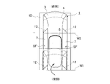
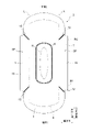
本発明に係る生理用ナプキン1は、図1~図3に示されるように、非肌側に配置されたポリエチレンシートなどからなる不透液性の裏面シート2と、肌側に配置されるとともに、経血やおりものなど(以下、まとめて体液ともいう。)を速やかに透過させる透液性の表面シート3と、これら両シート2,3間に介装された綿状パルプまたは合成パルプなどからなる吸収体4と、肌当接面側の両側部に長手方向のほぼ全長に亘って設けられたサイドシート7、7とを備え、かつ前記吸収体4の周囲においては、その上下端縁部では前記裏面シート2と表面シート3との外縁部がホットメルトなどの接着剤やヒートシール、超音波シール等の接合手段によって接合された前記吸収体4が介在しないエンドフラップ部EFが形成されるとともに、その両側縁部では吸収体4よりも側方に延出している前記裏面シート2と前記サイドシート7とがホットメルトなどの接着剤やヒートシール、超音波シール等の接合手段によって接合された前記吸収体4が介在しないサイドフラップ部SFが形成されたものである。なお、図示例では、前記吸収体4の形状保持および拡散性向上のために、前記吸収体4をクレープ紙又は不織布などからなる被包シート5で囲繞しているが、この被包シート5は設けなくてもよい。また、前記表面シート3の非肌側に隣接して、前記表面シート3とほぼ同形状の親水性の不織布などからなるセカンドシートを配設してもよい。
BEST MODE FOR CARRYING OUT THE INVENTION Hereinafter, embodiments of the present invention will be described in detail with reference to the drawings.
As shown in FIGS. 1 to 3, a sanitary napkin 1 according to the present invention includes a liquid-impermeable back sheet 2 made of a polyethylene sheet or the like placed on the non-skin side, and a liquid-impermeable back sheet 2 on the skin side. , a liquid-permeable surface sheet 3 through which menstrual blood, vaginal discharge, etc. (hereinafter also referred to collectively as body fluids) can quickly permeate, and cotton-like pulp or synthetic pulp, etc., interposed between the two sheets 2 and 3. and side sheets 7, 7 provided on both sides of the skin contact surface side over substantially the entire length in the longitudinal direction, and around the absorbent body 4, the upper and lower edges In the section, the outer edges of the back sheet 2 and the top sheet 3 are joined by a joining means such as hot-melt adhesive, heat sealing, ultrasonic sealing, or the like to form an end flap section EF in which the absorber 4 is not interposed. In addition, the back sheet 2 and the side sheets 7, which extend laterally beyond the absorbent body 4 at both side edges thereof, are joined by a joining means such as hot-melt adhesive, heat sealing, ultrasonic sealing, or the like. The side flap portion SF is formed without the absorbent body 4 interposed therebetween. In the illustrated example, the absorbent body 4 is surrounded by an enveloping sheet 5 made of crepe paper or non-woven fabric in order to retain the shape of the absorbent body 4 and improve diffusion. It does not have to be provided. A second sheet made of a hydrophilic non-woven fabric or the like having substantially the same shape as the topsheet 3 may be disposed adjacent to the non-skin side of the topsheet 3 .

本発明に係る生理用ナプキン1は、前記サイドシート7の幅方向内方側部分によって、肌当接面側の両側部に肌側に起立する立体ギャザーが形成されないものである。すなわち、前記サイドシート7の幅方向内方側部分には、弾性伸縮部材が配設されることなく、この弾性伸縮部材の収縮力によって肌側に起立しない構造となっており、表面シート3の肌側面に積層された状態で接合されている。 In the sanitary napkin 1 according to the present invention, the laterally inner side portions of the side sheets 7 do not form three-dimensional gathers standing on the skin side on both sides of the skin contact surface side. In other words, the inner portion of the side sheet 7 in the width direction is not provided with an elastic stretchable member, and the structure is such that the elastic stretchable member does not stand up against the skin due to the contractile force of the elastic stretchable member. It is joined in a layered state on the side of the skin.

なお、前記排血口対向部Hとは、生理用ナプキン1の装着時に着用者の排血口部(膣口を含む)に対向して配置される領域のことであり、そのナプキン長手方向の範囲は、後段で説明する幅方向折り線W1、W2の間の区間内に位置している。 The blood discharge port facing portion H is a region that is arranged to face the blood discharge port portion (including the vaginal opening) of the wearer when the sanitary napkin 1 is worn. The range is located within a section between width direction folding lines W1 and W2, which will be described later.

以下、さらに前記生理用ナプキン1の構造について詳述すると、
前記裏面シート2は、ポリエチレン等の少なくとも遮水性を有するシート材が用いられるが、蒸れ防止の観点から透湿性を有するものを用いるのが望ましい。この遮水・透湿性シート材としては、ポリエチレンやポリプロピレン等のオレフィン系樹脂中に無機充填剤を溶融混練してシートを成形した後、一軸または二軸方向に延伸することにより得られる微多孔性シートが好適に用いられる。前記裏面シート2の非肌側面(外面)にはナプキン長手方向に沿って1または複数条の、図示例では3条の粘着剤層9、9…が形成され、身体への装着時に生理用ナプキン1を下着に固定するようになっている。前記裏面シート2としては、プラスチックフィルムと不織布とを積層させたポリラミ不織布を用いてもよい。
The structure of the sanitary napkin 1 will be further detailed below.
For the back sheet 2, a sheet material having at least water impermeability such as polyethylene is used, but it is desirable to use a material having moisture permeability from the viewpoint of preventing stuffiness. The water-impervious/moisture-permeable sheet material is produced by melting and kneading an inorganic filler into an olefin resin such as polyethylene or polypropylene to form a sheet, and then stretching the sheet uniaxially or biaxially. A sheet is preferably used. On the non-skin side (outer surface) of the back sheet 2, one or a plurality of adhesive layers 9, 9, . . . are formed along the longitudinal direction of the napkin. 1 is fixed to the underwear. As the back sheet 2, a polylaminated nonwoven fabric obtained by laminating a plastic film and a nonwoven fabric may be used.

次いで、前記表面シート3は、有孔または無孔の不織布や多孔性プラスチックシートなどが好適に用いられる。不織布を構成する素材繊維としては、ポリエチレンまたはポリプロピレン等のオレフィン系、ポリエステル系、ポリアミド系等の合成繊維の他、レーヨンやキュプラ等の再生繊維、綿等の天然繊維とすることができ、スパンレース法、スパンボンド法、サーマルボンド法、メルトブローン法、ニードルパンチ法等の適宜の加工法によって得られた不織布を用いることができる。これらの加工法の内、スパンレース法は柔軟性、ドレープ性に富む点で優れ、サーマルボンド法は嵩高で圧縮復元性が高い点で優れている。前記表面シート3に多数の透孔を形成した場合には、体液が速やかに吸収されるようになり、ドライタッチ性に優れたものとなる。不織布の繊維は、長繊維または短繊維のいずれでもよいが、好ましくはタオル地の風合いを出すため短繊維を使用するのがよい。また、エンボス処理を容易とするために、比較的低融点のポリエチレンまたはポリプロピレン等のオレフィン系繊維のものを用いるのがよい。また、融点の高い繊維を芯とし融点の低い繊維を鞘とした芯鞘型繊維やサイド-バイ-サイド型繊維、分割型繊維の複合繊維を好適に用いることもできる。 Next, for the surface sheet 3, a perforated or non-perforated nonwoven fabric, a porous plastic sheet, or the like is preferably used. The material fibers that make up the nonwoven fabric include synthetic fibers such as olefins such as polyethylene or polypropylene, polyesters, and polyamides, as well as recycled fibers such as rayon and cupra, and natural fibers such as cotton. A nonwoven fabric obtained by an appropriate processing method such as a method, a spunbond method, a thermal bond method, a meltblown method, a needle punch method, or the like can be used. Among these processing methods, the spunlace method is superior in flexibility and drapeability, and the thermal bond method is superior in bulkiness and compression recovery. When a large number of through holes are formed in the surface sheet 3, body fluids are rapidly absorbed, and the dry touch property is excellent. The fibers of the non-woven fabric may be either long fibers or short fibers, but preferably short fibers are used in order to produce the feel of a terry cloth. Also, in order to facilitate embossing, it is preferable to use olefin fibers such as polyethylene or polypropylene having a relatively low melting point. In addition, composite fibers of core-sheath type fibers, side-by-side type fibers, and split type fibers having a high melting point fiber as a core and a low melting point fiber as a sheath can also be preferably used.

前記裏面シート2と表面シート3との間に介在される吸収体4は、たとえばパルプと高吸水性ポリマーとにより構成されている。前記高吸水性ポリマーは吸収体を構成するパルプ中に、例えば粒状粉として混入されている。前記パルプとしては、木材から得られる化学パルプ、溶解パルプ等のセルロース繊維や、レーヨン、アセテート等の人工セルロース繊維からなるものが挙げられ、広葉樹パルプよりは繊維長の長い針葉樹パルプの方が機能および価格の面で好適に使用される。 The absorbent body 4 interposed between the backsheet 2 and the topsheet 3 is made of, for example, pulp and superabsorbent polymer. The superabsorbent polymer is mixed, for example, in the form of granular powder in the pulp that constitutes the absorbent body. Examples of the pulp include chemical pulp obtained from wood, cellulose fibers such as dissolving pulp, and artificial cellulose fibers such as rayon and acetate. Softwood pulp with a longer fiber length is more functional and functional than hardwood pulp. It is preferably used in terms of price.

本生理用ナプキン1は、吸収体4の目付を低くした薄型のスリムナプキンであるのが好ましい。吸収体4の目付を低くすることにより、吸収体4の単位面積当たりの吸収容量が小さくなり、平面方向に体液が拡散しやすくなるという性質を有する。このため、サイドフラップ部SFを起立させることにより、吸収体4の端部からの漏れを防止するという本発明の効果が充分に発揮できるようになる。前記パルプの目付は、50~300g/m、好ましくは80~220g/mとするのがよく、前記高吸水性ポリマーの目付は、30~180g/m、好ましくは50~160g/mとするのがよい。これらパルプ及び高吸水性ポリマーの目付は、一定である必要はなく、吸収体の部位によって変化させても良い。例えば、排血口対向部Hにおいてパルプと高吸水性ポリマーの目付を高くした高吸収部を形成することができる。 The sanitary napkin 1 is preferably a thin slim napkin in which the fabric weight of the absorbent body 4 is low. By reducing the basis weight of the absorbent body 4, the absorption capacity per unit area of the absorbent body 4 is reduced, and the body fluid is easily diffused in the planar direction. Therefore, by erecting the side flap portions SF, the effect of the present invention of preventing leakage from the end portions of the absorbent body 4 can be fully exhibited. The basis weight of the pulp is 50 to 300 g/m 2 , preferably 80 to 220 g/m 2 , and the basis weight of the superabsorbent polymer is 30 to 180 g/m 2 , preferably 50 to 160 g/m 2 . 2 is better. The basis weight of these pulp and superabsorbent polymer does not need to be constant, and may be changed depending on the part of the absorbent. For example, in the blood outlet facing portion H, a highly absorbent portion can be formed in which the basis weight of pulp and superabsorbent polymer is increased.

また、前記吸収体4として、嵩を小さくできるエアレイド吸収体や、2層の不織布層間に高吸水性樹脂を配置してなるポリマーシートを用いてもよい。 Moreover, as the absorbent body 4, an air-laid absorbent body capable of reducing bulk, or a polymer sheet in which a superabsorbent resin is arranged between two layers of non-woven fabric may be used.

前記吸収体4には合成繊維を混合しても良い。前記合成繊維は、例えばポリエチレン又はポリプロピレン等のポリオレフィン系、ポリエチレンテレフタレートやポリブチレンテレフタレート等のポリエステル系、ナイロンなどのポリアミド系、及びこれらの共重合体などを使用することができるし、これら2種を混合したものであってもよい。また、融点の高い繊維を芯とし融点の低い繊維を鞘とした芯鞘型繊維やサイド-バイ-サイド型繊維、分割型繊維などの複合繊維も用いることができる。前記合成繊維は、体液に対する親和性を有するように、疎水性繊維の場合には親水化剤によって表面処理したものを用いるのが望ましい。 Synthetic fibers may be mixed in the absorber 4 . For the synthetic fibers, for example, polyolefins such as polyethylene or polypropylene, polyesters such as polyethylene terephthalate and polybutylene terephthalate, polyamides such as nylon, and copolymers thereof can be used. A mixture may also be used. In addition, composite fibers such as core-sheath type fibers, side-by-side type fibers, and split type fibers having a high-melting-point fiber as a core and a low-melting-point fiber as a sheath can also be used. In the case of hydrophobic fibers, the synthetic fibers are preferably surface-treated with a hydrophilizing agent so as to have affinity for body fluids.

前記表面シート3の幅寸法は、図示例では、図2及び図3の横断面図に示されるように、吸収体4の幅と略同等とされ、吸収体4を覆うだけに止まり、それより外方側は前記表面シート3とは別のサイドシート7、具体的には経血やおりもの等が浸透するのを防止する、あるいは肌触り感を高めるなどの目的に応じて、適宜の撥水処理または親水処理を施した不織布素材を用いて構成されたサイドシート7が配設されている。 In the illustrated example, the width dimension of the topsheet 3 is substantially equal to the width of the absorbent body 4, as shown in the cross-sectional views of FIGS. A side sheet 7 different from the top sheet 3 is provided on the outer side. A side sheet 7 is provided which is constructed using a treated or hydrophilic treated nonwoven fabric material.

かかるサイドシート7としては、天然繊維、合成繊維または再生繊維などを素材として、適宜の加工法によって形成されたものを使用することができるが、好ましくは体液の隠蔽性を高めるため、坪量を高めた不織布を用いるのがよい。具体的には、坪量を13~23g/mとして作製された不織布を用いるのが望ましく、かつ体液の透過を確実に防止するためにシリコン系、パラフィン系、アルキルクロミッククロリド系撥水剤などをコーティングした撥水処理不織布が好適に使用される。 The side sheet 7 may be made of natural fiber, synthetic fiber, regenerated fiber, or the like, and may be formed by an appropriate processing method. It is better to use an elevated nonwoven fabric. Specifically, it is desirable to use a non-woven fabric with a basis weight of 13 to 23 g/m 2 , and in order to reliably prevent permeation of body fluids, silicone-based, paraffin-based, alkylchromic chloride-based water repellents, etc. A water-repellent nonwoven fabric coated with is preferably used.

前記サイドシート7は、図2及び図3に示されるように、幅方向中間部より外側部分を所定の内側位置から裏面シート2の外縁までの範囲に亘ってホットメルトなどの接着剤によって接着され、これら前記サイドシート7と裏面シート2との積層シート部分により吸収体4の両側部に吸収体4が介在しないサイドフラップ部SFが形成されている。前記サイドシート7の内方側部分は表面シート3の肌側に積層された状態で吸収体4側(表面シート3の肌側面)に接着されている。 As shown in FIGS. 2 and 3, the side sheets 7 are bonded with an adhesive such as hot-melt over a range from a predetermined inner position to the outer edge of the back sheet 2 at the outer portion of the width direction middle portion. Laminated sheet portions of the side sheets 7 and the back sheet 2 form side flap portions SF on both sides of the absorbent body 4 in which the absorbent body 4 is not interposed. The inner side portion of the side sheet 7 is laminated on the skin side of the topsheet 3 and adhered to the absorber 4 side (the skin side of the topsheet 3).

本生理用ナプキン1では、ショーツに対する装着時に、ショーツのクロッチ部分の外側を巻き込むようにして折り返されるウイング状フラップが前記サイドフラップ部SFに設けられていない。生理用ナプキン1の側縁は、ショーツに装着した状態で、ショーツのクロッチ部分の側縁より内側に位置し、ショーツの脚周り開口部の外形線より外側にはみ出ない形状で形成され、ショーツと肌面との間に生理用ナプキン1の側部が挟み込まれないようにして装着される。サイドフラップ部SFの側縁(生理用ナプキン1の両側の外形線)は、長手方向中心線と平行する直線、幅方向内側又は外側に膨出する湾曲線のいずれか又はこれらの組み合わせでもよく、更に幅方向に凹凸を繰り返す波線を重ね合わせてもよい。また、後段で詳述するように、所定の長手方向の中間部が幅方向外側に膨出する形状で形成してもよい。 In the present sanitary napkin 1, the side flap portions SF are not provided with wing-shaped flaps that are folded back so as to involve the outside of the crotch portion of the shorts when worn on the shorts. The side edge of the sanitary napkin 1 is positioned inside the side edge of the crotch portion of the shorts when worn on the shorts, and is formed in a shape that does not protrude outside the outline of the opening around the leg of the shorts. The sanitary napkin 1 is worn so that the side part of the sanitary napkin 1 is not caught between the sanitary napkin 1 and the skin surface. The side edges of the side flap portion SF (outline lines on both sides of the sanitary napkin 1) may be straight lines parallel to the longitudinal center line, curved lines bulging inward or outward in the width direction, or a combination thereof. Furthermore, a wavy line that repeats unevenness in the width direction may be superimposed. Further, as will be described later in detail, the intermediate portion in the longitudinal direction may be formed in a shape that bulges outward in the width direction.

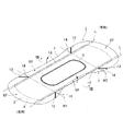
前記吸収体4が介在する本体部分における前記表面シート3の肌当接面には、図1に示されるように、外方側に拡散する体液を塞き止めて吸収体4に吸収・保持しやすくする、身体とのフィット性を高める、デザイン性を向上させ外観を良好にするなどのため、非肌側に窪ませたエンボス溝8が所定のパターンで形成されるのが好ましい。前記エンボス溝8は、表面シート3の外面側からの圧搾により、表面シート3から吸収体4にかけて一体的に窪ませた凹部である。図示例では、排血口対向部Hの周囲を囲む閉合した略長円形状に形成されているが、排血口対向部Hの両側にそれぞれ1条又は幅方向に離隔する複数条のエンボス溝を設けたり、排血口対向部Hの前側及び後側にそれぞれ装飾的なエンボス溝を設けたりしてもよい。 As shown in FIG. 1, the skin-contacting surface of the topsheet 3 in the body portion where the absorbent body 4 intervenes blocks body fluids diffusing outward and absorbs and retains them in the absorbent body 4. It is preferable that the embossed grooves 8 recessed on the non-skin side are formed in a predetermined pattern in order to make the garment easier to wear, to improve fit to the body, to improve the design and to improve the appearance. The embossed grooves 8 are recesses integrally recessed from the topsheet 3 to the absorbent body 4 by squeezing the outer surface of the topsheet 3 . In the illustrated example, the embossed grooves are formed in a substantially oval shape that surrounds the periphery of the blood discharge port-facing portion H, but each side of the blood discharge port-facing portion H has one or a plurality of embossed grooves spaced apart in the width direction. or decorative embossed grooves may be provided on the front and rear sides of the blood discharge port facing portion H, respectively.

図1に示されるように、前記表面シート3と裏面シート2との間に吸収体4が介在された本体部分の非肌当接面(裏面シート2の外面)には、下着に対する固定のためにナプキン長手方向に沿って1条又は複数条のズレ止め粘着剤層9、9…が形成されている。前記ズレ止め粘着剤層9は、個装状態で、剥離シート(図示せず)によって剥離可能に覆われている。前記剥離シートとしては、ズレ止め粘着剤層9に対する当接面に対し、例えばシリコーン系樹脂、フッ素系樹脂、または四フッ化エチレン系樹脂などの離型処理液を塗工するかスプレー塗布し離型処理した紙またはプラスチックシートを用いることができる。なお、特別に離型処理をしなくても、実質的に粘着力の低下を招かないものであれば、フィルムそのものであっても、不織布そのものであっても良い。前記ズレ止め粘着剤層9は、前記吸収体4が介在された本体部分のみに設けられ、サイドフラップ部SFには設けられていない。 As shown in FIG. 1, the non-skin-contacting surface (the outer surface of the backsheet 2) of the main body portion, in which the absorbent body 4 is interposed between the topsheet 3 and the backsheet 2, is provided for fixing to underwear. One or more anti-slip adhesive layers 9, 9... are formed along the longitudinal direction of the napkin. The slip-preventing pressure-sensitive adhesive layer 9 is releasably covered with a release sheet (not shown) in an individual packaging state. As for the release sheet, a release treatment liquid such as a silicone resin, a fluorine resin, or a tetrafluoroethylene resin is applied or sprayed to the contact surface of the anti-slip adhesive layer 9, and then released. Stamped paper or plastic sheets can be used. It should be noted that the film itself or the nonwoven fabric itself may be used as long as the adhesive strength does not substantially decrease even without special release treatment. The anti-slip pressure-sensitive adhesive layer 9 is provided only on the body portion where the absorbent body 4 is interposed, and is not provided on the side flap portions SF.

次に、前述した生理用ナプキン1の個装方法について、図4~図6に基づいて説明する。先ずはじめに、図4に示されるように、吸収体4の側縁又はその外側近傍位置を通る長手方向折り線Lにて、左右のサイドフラップ部SFをそれぞれ肌当接面側(表面シート3側)に、肌当接面同士が対面するように幅方向に折り畳む。次いで、個装シート10により生理用ナプキン1を長手方向に複数に折り畳みながら個装する。前記個装シート10による個装は、図5に示されるように、排血口対向部Hの後側位置を通る幅方向折り線W1にて、生理用ナプキン1の後側部分を個装シート10とともに肌当接面側(表面シート3側)に向けて長手方向に折り畳んだ後、図6に示されるように、排血口対向部Hの前側位置を通る幅方向折り線W2にて、生理用ナプキン1の前側部分を個装シート10とともに前述の折り返した後側部分の上側に向けて長手方向に折り畳み、個装シート10の開口した側縁部分をエンボス圧着、加熱融着、接着剤等、適宜の封鎖手段の単独または組み合わせによって封鎖するとともに、個装シート10の前後端縁を、接着剤により接合した後、好ましくはタブテープ11により封止する。 Next, a method for individually packaging the sanitary napkin 1 described above will be described with reference to FIGS. 4 to 6. FIG. First, as shown in FIG. 4, the left and right side flap portions SF are placed on the skin contact surface side (the top sheet 3 side) along the longitudinal fold line L passing through the side edge of the absorbent body 4 or a position near the outer side thereof. ), and folded in the width direction so that the skin-contacting surfaces face each other. Next, the sanitary napkin 1 is individually packaged while being folded into a plurality of pieces in the longitudinal direction using the individual packaging sheet 10 . As shown in FIG. 5, the individual packaging sheet 10 folds the rear portion of the sanitary napkin 1 into the individual packaging sheet along the width direction folding line W1 passing through the rear side position of the portion H facing the blood discharge port. After folding in the longitudinal direction along with 10 toward the skin contact surface side (top sheet 3 side), as shown in FIG. The front part of the sanitary napkin 1 is folded in the longitudinal direction along with the individual packaging sheet 10 toward the upper side of the folded back part, and the opened side edge part of the individual packaging sheet 10 is embossed, pressed, heat-sealed, or adhesively bonded. The front and rear edges of the individual packaging sheet 10 are joined with an adhesive, and then preferably sealed with a tab tape 11 while blocking by an appropriate blocking means alone or in combination.

前記サイドフラップ部SFを長手方向折り線Lにて幅方向に折り畳んだ状態を保持するため、前記サイドフラップ部SFが長手方向折り線Lにて折り畳まれた状態で仮止めされ、個装されるようにするのが好ましい。これにより、サイドフラップ部SFを幅方向に折り畳んだ後、生理用ナプキン1を個装シート10とともに長手方向に折り畳む工程において、サイドフラップ部SFが幅方向に折り畳まれた状態が解除されなくなり、製造が容易になる。前記仮止め手段としては、公知の形態を広く用いることが可能であり、例えば、簡単に手で剥がせる程度の粘着力を有する粘着剤による接着、ローラー等による圧着、サイドシート7として剛性の高い素材を用いることにより強い折り癖を付加することなどを挙げることができる。 In order to maintain the state in which the side flap portions SF are folded in the width direction along the longitudinal folding lines L, the side flap portions SF are temporarily fixed in the folded state along the longitudinal folding lines L and individually packaged. It is preferable to As a result, in the step of folding the sanitary napkin 1 along with the individual packaging sheet 10 in the longitudinal direction after folding the side flap portions SF in the width direction, the state in which the side flap portions SF are folded in the width direction is not released, and the manufacturing process is completed. becomes easier. As the temporary fixing means, it is possible to use a wide range of known forms, for example, adhesion with an adhesive having adhesive strength to the extent that it can be easily peeled off by hand, pressure bonding with a roller or the like, and high rigidity as the side sheet 7 Adding a strong crease by using the material can be mentioned.

本生理用ナプキン1では、図1に示されるように、前記サイドフラップ部SFに、前記長手方向折り線Lと幅方向折り線W1、W2との交点又はその近傍位置を起点とする圧搾部12が設けられている。つまり、左右のサイドフラップ部SFにはそれぞれ、排血口対向部Hの後側に設けられた幅方向折り線W1の直ぐ後側に圧搾部12が設けられるとともに、排血口対向部Hの前側に設けられた幅方向折り線W2の直ぐ前側に圧搾部12が設けられている。 In the present sanitary napkin 1, as shown in FIG. 1, the side flap portions SF are provided with compressed portions 12 starting from intersections of the longitudinal folding lines L and the widthwise folding lines W1 and W2 or positions in the vicinity thereof. is provided. That is, each of the left and right side flap portions SF is provided with a compressing portion 12 immediately behind the width direction folding line W1 provided on the rear side of the blood discharge port facing portion H, and the blood discharge port facing portion H is provided with a pressing portion 12. A pressing portion 12 is provided immediately in front of the width direction folding line W2 provided on the front side.

このように構成された生理用ナプキン1の効果について説明すると、本生理用ナプキン1では、サイドフラップ部の側縁に側方に突出するウイング状フラップが設けられないにもかかわらず、ウイング状フラップを有するものと同様にサイドフラップ部SFを長手方向折り線Lにて肌当接面側に向けて幅方向に折り畳んだ上で、幅方向折り線W1、W2にて長手方向に折り畳むことにより個装されている。このとき、前記サイドフラップ部SFには、前記長手方向折り線Lと幅方向折り線W1、W2との交点又はその近傍位置を起点とする圧搾部12が設けられている。これによって、個装から取り出して下着に装着した状態では、図7及び図8に示されるように、左右それぞれのサイドフラップ部SFの前後に設けられた圧搾部12、12で挟まれた区間(排血口対向部Hの両側部に対応する前後方向区間のサイドフラップ部SF)が、前記圧搾部12を基端として、個装の際の折り癖によって肌側に起立するようになり、この起立したサイドフラップ部SFが立体ギャザーのように作用して起立側端部が排血口対向部Hの両側の身体にフィットするため、肌当接面側の両側部に肌側に起立する立体ギャザーが設けられない生理用ナプキンであっても、生理用ナプキン1の両側部における身体との隙間が低減して、液漏れが生じにくくなる。しかも、前記サイドフラップ部SFは、弾性伸縮部材が配設されることなく肌側に起立するように構成されているため、着用時に排血口対向部Hの両側部分や脚の付け根の内側部分に柔軟にフィットし、締め付け感などの違和感を感じることなく、付け心地が良好になる。 The effect of the sanitary napkin 1 configured in this manner will be described. Although the sanitary napkin 1 is not provided with wing-shaped flaps protruding sideways from the side edges of the side flap portions, the wing-shaped flaps are not provided. After folding the side flap part SF in the width direction toward the skin contact surface side along the longitudinal folding line L, and then folding it in the longitudinal direction along the width direction folding lines W1 and W2, the individual is dressed. At this time, the side flap portion SF is provided with a pressing portion 12 whose starting point is the intersection of the longitudinal folding line L and the widthwise folding lines W1 and W2 or a position in the vicinity thereof. As a result, in a state where it is taken out from the individual packaging and worn on underwear, as shown in FIGS. 7 and 8, a section ( The side flap portions SF in the front-rear direction section corresponding to both side portions of the blood discharge port facing portion H), with the compressed portion 12 as a base end, stand up on the skin side due to the crease of individual packaging. The raised side flap portions SF act like three-dimensional gathers, and the raised side ends fit the body on both sides of the blood discharge port facing portion H. Even with a sanitary napkin that does not have gathers, the gaps between both sides of the sanitary napkin 1 and the body are reduced, and liquid leakage is less likely to occur. Moreover, since the side flap portions SF are configured to stand on the skin side without being provided with an elastic stretchable member, both sides of the blood discharge port facing portion H and the inner portion of the base of the leg are worn. It fits flexibly, and it is comfortable to wear without feeling discomfort such as a feeling of tightness.

また、排血口対向部Hの両側部でサイドフラップ部SFが起立しており、立体ギャザーのように身体の動きに追従しやすいため、より効果的に漏れが防止できるようになる。更に、起立したサイドフラップ部SFが排血口対向部Hの両側部分又は脚の付け根部分に常に当たっている感覚が実感できることで、使用者の漏れに対する不安感が軽減し、安心感を持って使用することができるようになる。 In addition, since the side flaps SF are erected on both sides of the blood discharge port facing portion H and easily follow the movement of the body like three-dimensional gathers, leakage can be prevented more effectively. Furthermore, the user can feel that the upright side flap part SF is constantly touching both sides of the blood discharge port facing part H or the base of the leg, so that the user's anxiety about leakage is reduced and the user can use it with a sense of security. be able to

更に、本生理用ナプキン1では、サイドフラップ部SFを長手方向折り線Lにて幅方向に折り畳んだ後、生理用ナプキン1を幅方向折り線W1、W2にて長手方向に折り畳んで個装しているため、個装から取り出した状態では、図7に示されるように、サイドフラップ部SFの前後に幅方向に横断する山折りの折り癖14が形成されるとともに、サイドフラップ部SFを幅方向に折り畳んだ基端部に長手方向に沿って谷折りの折り癖15が形成されるようになり、これらの折り癖14、15によって、前後の圧搾部12、12間のサイドフラップ部SFが更に肌側に起立しやすくなる。 Further, in the present sanitary napkin 1, after the side flap portions SF are folded in the width direction along the longitudinal fold lines L, the sanitary napkin 1 is folded in the longitudinal direction along the width direction fold lines W1 and W2 for individual packaging. Therefore, when removed from the individual package, as shown in FIG. 7, the side flap portion SF has a mountain-fold crease 14 crossing the width direction in the front and rear of the side flap portion SF, and the side flap portion SF extends in the width direction. A valley-fold crease 15 is formed along the longitudinal direction at the base end folded in the direction, and these creases 14, 15 form the side flap portions SF between the front and rear compressed portions 12, 12. Furthermore, it becomes easier to stand up on the skin side.

前記圧搾部12について更に詳細に説明すると、前記圧搾部12は、前記サイドシート7と裏面シート2とが直接積層されたサイドフラップ部SFに対し、前記サイドシート7の外面側からの圧搾により、肌当接面側に非肌側に窪む凹部が形成されるようにしてもよいし、前記裏面シート2の外面側からの圧搾により、非肌当接面側に肌側に窪む凹部が形成されるようにしてもよい。前記サイドシート7の外面側からの圧搾により形成する場合、加工工程の簡素化の観点から、本体部分に設けられるエンボス溝8を加工する際のエンボスロールによる圧搾と同時に施すようにするのが好ましい。 More specifically, the pressing portion 12 presses the side flap portion SF, in which the side sheet 7 and the back sheet 2 are directly laminated, from the outer surface side of the side sheet 7. A concave portion recessed toward the non-skin side may be formed on the skin-contacting surface side, or a concave portion recessed toward the skin side may be formed on the non-skin-contacting surface side by squeezing the backsheet 2 from the outer surface side. may be formed. In the case of forming by pressing from the outer surface side of the side sheet 7, from the viewpoint of simplification of the processing process, it is preferable to apply simultaneously with pressing by an embossing roll when processing the embossed grooves 8 provided in the main body portion. .

前記圧搾部12は、前記長手方向折り線Lと幅方向折り線W1、W2との交点又はその近傍を起点として形成されている。つまり、前記圧搾部12の幅方向内側の端縁が前記交点又はその近傍に位置している。これにより、この交点から延びる圧搾部12を基端として、前後の圧搾部12、12間のサイドフラップ部SFが肌側に起立しやすくなる。前記圧搾部12は、長手方向折り線L及び幅方向折り線W1、W2を横断することなく、幅方向内側の端縁以外は前記折り線L、W1、W2と交差しないように配置されている。 The compressed portion 12 is formed starting from the intersection of the longitudinal folding line L and the widthwise folding lines W1, W2 or the vicinity thereof. That is, the inner edge in the width direction of the pressing portion 12 is positioned at or near the intersection. This makes it easier for the side flap portions SF between the front and rear compressed portions 12, 12 to stand up on the skin side, with the compressed portions 12 extending from this intersection as base ends. The compressed portion 12 is arranged so as not to cross the longitudinal folding lines L and the widthwise folding lines W1 and W2, and not to cross the folding lines L, W1 and W2 except for the inner edges in the width direction. .

前記圧搾部12は、図1に示されるように、生理用ナプキン1の平面視で、幅方向外側に向かうに従って徐々に、排血口対向部Hと長手方向反対側に傾斜する形状で形成するのが好ましい。即ち、圧搾部12の幅方向内側の端縁より幅方向外側の端縁の方が排血口対向部Hから長手方向に遠い位置に配置されている。このような形状で圧搾部12を設けることにより、生理用ナプキン1を個装から取り出した状態で前記圧搾部12を基端としてサイドフラップ部SFが肌側に起立しやすくなる。 As shown in FIG. 1, the compressed portion 12 is formed in a shape that gradually inclines in the longitudinal direction opposite to the blood discharge port facing portion H toward the outside in the width direction in a plan view of the sanitary napkin 1. is preferred. That is, the widthwise outer edge of the compressed portion 12 is arranged at a position farther from the blood discharge port facing portion H in the longitudinal direction than the widthwise inner edge. By providing the pressing portion 12 in such a shape, the side flap portion SF can easily stand up on the skin side with the pressing portion 12 as the base end when the sanitary napkin 1 is taken out from the individual package.

前記圧搾部12とそれに隣接する幅方向折り線W1又はW2とのナプキン長手方向の最小離隔距離は、0~10mm、好ましくは0~5mm、より好ましくは0~2mmとするのがよい。また、前記圧搾部12と長手方向折り線Lとのナプキン幅方向の最小離隔距離は、0~10mm、好ましくは0~5mm、より好ましくは0~2mmとするのがよい。圧搾部12の起点を幅方向折り線W1、W2及び長手方向折り線Lに近接する位置に設けることにより、前後の圧搾部12、12間のサイドフラップ部SFが圧搾部12を基端として肌側に起立しやすくなる。 The minimum separation distance in the longitudinal direction of the napkin between the compressed portion 12 and the adjacent width direction folding line W1 or W2 is preferably 0 to 10 mm, preferably 0 to 5 mm, more preferably 0 to 2 mm. Moreover, the minimum separation distance between the compressed portion 12 and the longitudinal folding line L in the width direction of the napkin is preferably 0 to 10 mm, preferably 0 to 5 mm, and more preferably 0 to 2 mm. By providing the starting point of the pressing portion 12 at a position close to the width direction folding lines W1, W2 and the longitudinal folding line L, the side flap portion SF between the front and rear pressing portions 12, 12 is formed with the pressing portion 12 as the base end. Easier to stand on your side.

前記圧搾部12は、図1に示されるように、等幅の直線で形成することができる。また、図9(A)に示されるように、幅方向外側に向けて徐々に拡幅する略三角形状で形成することにより、圧搾部12の面積を相対的に大きくし、前後の圧搾部12、12間のサイドフラップ部SFが、圧搾部12を基端として肌側に起立しやすくなるようにしてもよい。また、前記圧搾部12は、同図9(B)に示されるように、曲線で形成してもよい。曲線が膨出する方向は、図示例のように幅方向内側でもよいし、逆に幅方向外側としてもよい。 The compression part 12 can be formed in a straight line of equal width, as shown in FIG. In addition, as shown in FIG. 9A, by forming a generally triangular shape that gradually widens toward the outside in the width direction, the area of the pressing portion 12 is relatively increased, and the front and rear pressing portions 12, You may make it easy for the side flap part SF between 12 to stand up on the skin side by using the pressing part 12 as a base end. Also, the pressing portion 12 may be formed in a curved line as shown in FIG. 9(B). The direction in which the curved line bulges out may be the inner side in the width direction as in the illustrated example, or may be the outer side in the width direction.

前記圧搾部12を基端としたサイドフラップ部SFの肌側への起立が確実に成されるようにするため、図10に示されるように、前記排血口対向部Hの前側及び後側に隣接する幅方向折り線W1、W2における前記長手方向折り線Lより幅方向外側の区間に沿って幅方向折り線上圧搾部16が設けられるとともに、前記排血口対向部Hの前側及び後側に隣接する幅方向折り線W1、W2の間の長手方向折り線Lに沿って長手方向折り線上圧搾部17が設けられるようにするのが望ましい。すなわち、左右それぞれのサイドフラップ部SFの前後に配置された圧搾部12、12の間に配置された幅方向折り線W1、W2及び長手方向折り線Lに沿って、それぞれ幅方向折り線上圧搾部16及び長手方向折り線上圧搾部17を、平面視略コの字形に設けている。このように、折り線上に沿って圧搾部16、17を設けることにより、各折り線で折り曲げた際、硬化して剛性が増した折り線での折り癖が明確に形成され、この折り癖によって、個装から取り出した際、サイドフラップ部SFが肌側に起立しやすくなる。前記幅方向折り線上圧搾部16及び長手方向折り線上圧搾部17を形成する際の圧搾方向は任意であるが、前記幅方向折り線上圧搾部16は、肌側に突出する山折りとなるのを考慮すると、裏面シート2の外面側からの圧搾により裏面シート2の外面に肌側に窪む凹溝が形成されるようにするのが好ましく、前記長手方向折り線上圧搾部17は、非肌側に突出する谷折りとなるのを考慮すると、サイドシート7の外面側からの圧搾によりサイドシート7の外面に非肌側に窪む凹溝が形成されるようにするのが好ましい。また、パターンとしては、折り線が延びる方向に沿って連続して圧搾した連続線でもよいし、折り線が延びる方向に沿って圧搾部と非圧搾部とが交互に複数配置された間欠線としてもよい。 In order to ensure that the side flap portion SF with the pressing portion 12 as the base end is raised toward the skin side, as shown in FIG. Width direction fold line compression portions 16 are provided along width direction outer sections of the longitudinal fold line L in the width direction fold lines W1 and W2 adjacent to the above, and the front side and the rear side of the blood discharge port facing portion H It is desirable that the longitudinal fold line pressing portion 17 is provided along the longitudinal fold line L between the width direction fold lines W1 and W2 adjacent to the . That is, along the width direction fold lines W1 and W2 and the longitudinal fold line L arranged between the compression portions 12 and 12 arranged in front and behind the left and right side flap portions SF, respectively, the width direction fold line compression portion 16 and longitudinal folding line compression part 17 are provided in a substantially U-shape in plan view. By providing the pressed portions 16 and 17 along the folding lines in this way, when the sheet is folded along the respective folding lines, the creases at the creases hardened and increased in rigidity are clearly formed. , When taken out from the individual package, the side flap portion SF can easily stand up on the skin side. The pressing direction when forming the width direction fold line compressed portion 16 and the longitudinal fold line compressed portion 17 is arbitrary, but the width direction fold line compressed portion 16 should not be a mountain fold protruding to the skin side. In consideration of this, it is preferable that the outer surface of the backsheet 2 is pressed from the outer surface side to form grooves that are recessed toward the skin side, and the longitudinal fold line pressing portions 17 are preferably formed on the outer surface of the backsheet 2 on the non-skin side. Considering that the valley folds protrude outward, it is preferable that the outer surface of the side sheet 7 is pressed from the outer surface side to form a concave groove that is recessed toward the non-skin side. The pattern may be a continuous line that is continuously compressed along the direction in which the fold line extends, or an intermittent line in which a plurality of compressed portions and non-compressed portions are alternately arranged along the direction in which the fold line extends. good too.

一方で、図1に示されるように、幅方向折り線W1、W2及び長手方向折り線Lに沿う圧搾部が設けられないようにしてもよい。この場合は、個装の際の折り癖によってサイドフラップ部SFが肌側に起立するようになる。 On the other hand, as shown in FIG. 1, the pressed portions along the width direction folding lines W1 and W2 and the longitudinal direction folding line L may not be provided. In this case, the side flap portions SF stand up on the skin side due to the crease in individual packaging.

また、他の変形例として、図11に示されるように、前記サイドフラップ部SFに、幅方向外側に膨出する膨出部18が設けられるようにしてもよい。これにより、装着時にサイドフラップ部SFが肌側に起立した際、前記膨出部18によって肌側への起立高さが高くなり、前記膨出部18の先端が肌面に密着して、より効果的に漏れが防止できるようになる。前記サイドフラップ部SFが前後の圧搾部12、12を基端として肌側に起立するため、前記膨出部18は、前後の圧搾部12、12の間に形成するのが好ましい。図示例では、前記膨出部18は、長手方向両端に段差部を有する長手方向にほぼ直線の形状で形成されているが、幅方向外側に膨出する曲線などの形状で形成してもよい。 As another modification, as shown in FIG. 11, the side flap portion SF may be provided with a bulging portion 18 that bulges outward in the width direction. As a result, when the side flap portion SF stands up on the skin side at the time of wearing, the rising height toward the skin side is increased by the bulging portion 18, and the tip of the bulging portion 18 is in close contact with the skin surface, making it more comfortable. Leakage can be effectively prevented. Since the side flap portion SF stands up on the skin side with the front and rear compressed portions 12, 12 as base ends, the bulging portion 18 is preferably formed between the front and rear compressed portions 12, 12. In the illustrated example, the bulging portion 18 is formed in a substantially linear shape in the longitudinal direction with stepped portions at both ends in the longitudinal direction, but it may be formed in a curved shape or the like that bulges outward in the width direction. .

〔他の形態例〕
上記形態例では、排血口対向部Hが生理用ナプキン1の長手方向中央部に位置し、個装の際に生理用ナプキン1を長手方向に複数に折り畳む幅方向折り線W1、W2が、排血口対向部Hの前側及び後側にそれぞれ1本ずつ設けられた3つ折りの場合を例に挙げ説明したが、排血口対向部Hが生理用ナプキン1の前側寄りに位置し、排血口対向部Hの後側に複数の幅方向折り線が設けられた4つ折り以上の複数折りの生理用ナプキン1でもよい。4つ折り以上の生理用ナプキン1の場合、前記圧搾部12は、排血口対向部Hの直ぐ前側及び後側に設けられた幅方向折り線W1、W2の近傍のみにそれぞれ設けられ、それより外側の幅方向折り線の近傍には設けられていない。
[Other form examples]
In the above embodiment, the blood discharge port facing portion H is located in the longitudinal central portion of the sanitary napkin 1, and the width direction fold lines W1 and W2 along which the sanitary napkin 1 is folded into a plurality of pieces in the longitudinal direction when individual packaging is performed. Although the case where the blood discharge port facing portion H is provided with one each on the front side and the back side of the sanitary napkin 1 has been described as an example, the blood discharge port facing portion H is positioned closer to the front side of the sanitary napkin 1, and the blood discharge port facing portion H is positioned closer to the front side of the sanitary napkin 1. The sanitary napkin 1 may be folded into four or more, in which a plurality of width-direction folding lines are provided on the rear side of the blood port-facing portion H. In the case of the sanitary napkin 1 folded in four or more, the compressing portions 12 are provided only in the vicinity of the width direction folding lines W1 and W2 provided on the immediate front side and rear side of the blood discharge port facing portion H, respectively. It is not provided in the vicinity of the outer width direction folding line.

1…生理用ナプキン、2…裏面シート、3…表面シート、4…吸収体、5…被包シート、7…サイドシート、8…エンボス溝、、10…個装シート、11…タブテープ、12…圧搾部、14・15…折り癖、16…幅方向折り線上圧搾部、17長手方向折り線上圧搾部、18…膨出部、H…排血口対向部、EF…エンドフラップ部、SF…サイドフラップ部、L…長手方向折り線、W1・W2…幅方向折り線 DESCRIPTION OF SYMBOLS 1... Sanitary napkin, 2... Back sheet, 3... Top sheet, 4... Absorbent body, 5... Wrapping sheet, 7... Side sheet, 8... Embossed groove, 10... Individual packaging sheet, 11... Tab tape, 12... Compressed parts 14 and 15: Creases 16: Width direction fold line compressed part 17 Longitudinal fold line compressed part 18: Bulging part H: Blood outlet facing part EF: End flap part SF: Side Flap part, L...Longitudinal fold line, W1/W2...Width direction fold line

Claims (7)

透液性の表面シートと不透液性の裏面シートとの間に吸収体が介在されるとともに、前記吸収体の両側部に吸収体が介在しないサイドフラップ部が形成された吸収性物品において、
前記サイドフラップ部には、装着時に下着のクロッチ部分の外側を巻き込むようにして折り返されるウイング状フラップが設けられておらず、
前記吸収性物品は、前記吸収体の側縁又はその外側位置を通る長手方向折り線にて、前記サイドフラップ部が肌当接面側に折り畳まれるとともに、少なくとも排血口対向部の前側位置及び後側位置をそれぞれ通る幅方向折り線にて長手方向に折り畳まれて個装され、
前記サイドフラップ部に、前記長手方向折り線と幅方向折り線との交点又はその近傍位置を起点とする圧搾部が設けられていることを特徴とする吸収性物品。
An absorbent article in which an absorber is interposed between a liquid-permeable topsheet and a liquid-impermeable backsheet, and side flap portions are formed on both sides of the absorber without an absorber interposed therebetween,
The side flap portion is not provided with a wing-shaped flap that is folded back so as to involve the outside of the crotch portion of the underwear when worn,
In the absorbent article, the side flap portion is folded toward the skin contact surface along a longitudinal fold line passing through the side edge or the outer side of the absorbent body, and at least the front side position of the blood discharge port facing portion Individually packaged by being folded in the longitudinal direction along the width direction folding lines passing through the rear positions,
The absorbent article according to claim 1, wherein the side flap portion is provided with a compressed portion starting from an intersection point of the longitudinal fold line and the width direction fold line or a position in the vicinity thereof.
前記圧搾部は、幅方向外側に向かうに従って徐々に、前記排血口対向部と長手方向反対側に傾斜する形状で形成されている請求項1記載の吸収性物品。 2. The absorbent article according to claim 1, wherein the compressed portion is formed in a shape that gradually inclines toward the opposite side in the longitudinal direction of the blood discharge port facing portion toward the outer side in the width direction. 前記排血口対向部の前側及び後側に隣接する前記幅方向折り線における前記長手方向折り線より幅方向外側の区間に沿って幅方向折り線上圧搾部が設けられるとともに、前記排血口対向部の前側及び後側に隣接する前記幅方向折り線の間の前記長手方向折り線に沿って長手方向折り線上圧搾部が設けられている請求項1、2いずれかに記載の吸収性物品。 Width direction fold line pressing portions are provided along a section of the width direction fold line adjacent to the front side and the rear side of the blood discharge port facing portion, and are located outside the longitudinal direction fold line in the width direction. 3. The absorbent article according to claim 1 or 2, wherein a longitudinal fold line compressed portion is provided along the longitudinal fold line between the width fold lines adjacent to the front side and the rear side of the portion. 前記幅方向折り線及び前記長手方向折り線に沿って圧搾部が設けられていない請求項1、2いずれかに記載の吸収性物品。 The absorbent article according to any one of claims 1 and 2, wherein no compressed portion is provided along the width direction fold line and the longitudinal direction fold line. 前記圧搾部は、等幅の直線若しくは曲線又は幅方向外側に向けて徐々に拡幅する形状で形成されている請求項1~3いずれかに記載の吸収性物品。 4. The absorbent article according to any one of claims 1 to 3, wherein the compressed portion is formed in a straight line or curved line of equal width, or in a shape gradually widening outward in the width direction. 前記サイドフラップ部に、幅方向外側に膨出する膨出部が設けられ、装着時に前記サイドフラップ部が肌側に起立した際、前記膨出部の先端が肌面に密着するようになっている請求項1~5いずれかに記載の吸収性物品。 The side flap portion is provided with a bulging portion that bulges outward in the width direction, and when the side flap portion stands on the skin side when worn, the tip of the bulging portion comes into close contact with the skin surface. The absorbent article according to any one of claims 1 to 5. 前記サイドフラップ部が前記長手方向折り線にて折り畳まれた状態で仮止めされ、個装されている請求項1~6いずれかに記載の吸収性物品。 7. The absorbent article according to any one of claims 1 to 6, wherein the side flap portions are temporarily fixed while being folded along the longitudinal folding lines, and individually packaged.
JP2019139957A 2019-07-30 2019-07-30 absorbent article Active JP7209600B2 (en)

Priority Applications (2)

Application Number Priority Date Filing Date Title
JP2019139957A JP7209600B2 (en) 2019-07-30 2019-07-30 absorbent article
PCT/JP2020/029088 WO2021020452A1 (en) 2019-07-30 2020-07-29 Absorbent article

Applications Claiming Priority (1)

Application Number Priority Date Filing Date Title
JP2019139957A JP7209600B2 (en) 2019-07-30 2019-07-30 absorbent article

Publications (2)

Publication Number Publication Date
JP2021020008A JP2021020008A (en) 2021-02-18
JP7209600B2 true JP7209600B2 (en) 2023-01-20

Family

ID=74229198

Family Applications (1)

Application Number Title Priority Date Filing Date
JP2019139957A Active JP7209600B2 (en) 2019-07-30 2019-07-30 absorbent article

Country Status (2)

Country Link
JP (1) JP7209600B2 (en)
WO (1) WO2021020452A1 (en)

Citations (2)

* Cited by examiner, † Cited by third party
Publication number Priority date Publication date Assignee Title
JP2008500107A (en) 2004-05-24 2008-01-10 ザ プロクター アンド ギャンブル カンパニー Absorbent article with conforming guide
JP2012179242A (en) 2011-03-01 2012-09-20 Unicharm Corp Package body of absorbent article

Family Cites Families (2)

* Cited by examiner, † Cited by third party
Publication number Priority date Publication date Assignee Title
JP2909877B2 (en) * 1995-02-02 1999-06-23 ザ、プロクター、エンド、ギャンブル、カンパニー Absorbent articles
JP6152518B2 (en) * 2014-08-29 2017-06-28 大王製紙株式会社 Absorbent articles

Patent Citations (2)

* Cited by examiner, † Cited by third party
Publication number Priority date Publication date Assignee Title
JP2008500107A (en) 2004-05-24 2008-01-10 ザ プロクター アンド ギャンブル カンパニー Absorbent article with conforming guide
JP2012179242A (en) 2011-03-01 2012-09-20 Unicharm Corp Package body of absorbent article

Also Published As

Publication number Publication date
WO2021020452A1 (en) 2021-02-04
JP2021020008A (en) 2021-02-18

Similar Documents

Publication Publication Date Title
JP4789793B2 (en) Absorbent articles
JP5727246B2 (en) Absorbent articles
WO2017217354A1 (en) Absorbent article
JP6375354B2 (en) Absorbent articles
JP2018086170A5 (en)
CN110461292B (en) Absorbent article
JP4359020B2 (en) Sanitary napkin
JP3776014B2 (en) Absorbent article and manufacturing method thereof
JP6073619B2 (en) Absorbent articles
JP6232459B2 (en) Absorbent articles
JP7209600B2 (en) absorbent article
JP7194612B2 (en) absorbent article
JPH10295724A (en) Absorptive article for body fluid treatment
JP7164370B2 (en) absorbent article
JP2017153768A5 (en)
JP7431700B2 (en) absorbent articles
JP7178288B2 (en) absorbent article
JP7361556B2 (en) absorbent articles
JP6152517B2 (en) Absorbent articles
JP6458186B2 (en) Absorbent articles
JP7263189B2 (en) absorbent article
WO2023074201A1 (en) Absorbent article
JP4145692B2 (en) Absorbent articles
JP6898978B2 (en) Absorbent article
JP7157594B2 (en) absorbent article

Legal Events

Date Code Title Description
A621 Written request for application examination

Free format text: JAPANESE INTERMEDIATE CODE: A621

Effective date: 20220425

TRDD Decision of grant or rejection written
A01 Written decision to grant a patent or to grant a registration (utility model)

Free format text: JAPANESE INTERMEDIATE CODE: A01

Effective date: 20221222

A61 First payment of annual fees (during grant procedure)

Free format text: JAPANESE INTERMEDIATE CODE: A61

Effective date: 20230110

R150 Certificate of patent or registration of utility model

Ref document number: 7209600

Country of ref document: JP

Free format text: JAPANESE INTERMEDIATE CODE: R150