WO2013106041A2 - Electronic device - Google Patents
Electronic device Download PDFInfo
- Publication number
- WO2013106041A2 WO2013106041A2 PCT/US2012/032681 US2012032681W WO2013106041A2 WO 2013106041 A2 WO2013106041 A2 WO 2013106041A2 US 2012032681 W US2012032681 W US 2012032681W WO 2013106041 A2 WO2013106041 A2 WO 2013106041A2
- Authority
- WO
- WIPO (PCT)
- Prior art keywords
- compound
- layer
- group
- formula
- deuterated
- Prior art date
Links
- VPOXSNWWTXGGHD-UHFFFAOYSA-N CCCCCCCCc1cc2c(-c(cc3)ccc3-c3ccccc3)c(ccc(CCCCCCCC)c3)c3c(-c(cc3)ccc3-c3ccccc3)c2cc1 Chemical compound CCCCCCCCc1cc2c(-c(cc3)ccc3-c3ccccc3)c(ccc(CCCCCCCC)c3)c3c(-c(cc3)ccc3-c3ccccc3)c2cc1 VPOXSNWWTXGGHD-UHFFFAOYSA-N 0.000 description 1
- CYIMYPNWBKBGSN-UHFFFAOYSA-N CCCc(cc(cc1)-c2c(cccc3)c3c(-c(cc3)cc(CCC)c3-c3c(cccc4)c4ccc3)c3c2cccc3)c1-c1cc(cccc2)c2cc1 Chemical compound CCCc(cc(cc1)-c2c(cccc3)c3c(-c(cc3)cc(CCC)c3-c3c(cccc4)c4ccc3)c3c2cccc3)c1-c1cc(cccc2)c2cc1 CYIMYPNWBKBGSN-UHFFFAOYSA-N 0.000 description 1
- VXOYCDSVXVUFMM-UHFFFAOYSA-N CCCc(cc(cc1)C(C2C=CC=CC22)=C(C=CC=C3)C3=C2C(CC2)=CC(CCC)=C2C2=CC=CC3C=CC=CC23)c1-c1cc2ccccc2cc1 Chemical compound CCCc(cc(cc1)C(C2C=CC=CC22)=C(C=CC=C3)C3=C2C(CC2)=CC(CCC)=C2C2=CC=CC3C=CC=CC23)c1-c1cc2ccccc2cc1 VXOYCDSVXVUFMM-UHFFFAOYSA-N 0.000 description 1
- GIMPOLBNLZJDGO-UHFFFAOYSA-N Nc1cc2c(-c(cc3)ccc3-c3ccccc3)c(ccc(N)c3)c3c(-c(cc3)ccc3-c3ccccc3)c2cc1 Chemical compound Nc1cc2c(-c(cc3)ccc3-c3ccccc3)c(ccc(N)c3)c3c(-c(cc3)ccc3-c3ccccc3)c2cc1 GIMPOLBNLZJDGO-UHFFFAOYSA-N 0.000 description 1
- IIBSMOAYVQUAMG-UHFFFAOYSA-N c(cc1)ccc1-c(cc1)cc2c1c(-c(cc1)ccc1-c1c(cccc3)c3ccc1)c(cccc1)c1c2-c(cc1)ccc1-c1cc2ccccc2cc1 Chemical compound c(cc1)ccc1-c(cc1)cc2c1c(-c(cc1)ccc1-c1c(cccc3)c3ccc1)c(cccc1)c1c2-c(cc1)ccc1-c1cc2ccccc2cc1 IIBSMOAYVQUAMG-UHFFFAOYSA-N 0.000 description 1
Classifications
-
- C—CHEMISTRY; METALLURGY
- C09—DYES; PAINTS; POLISHES; NATURAL RESINS; ADHESIVES; COMPOSITIONS NOT OTHERWISE PROVIDED FOR; APPLICATIONS OF MATERIALS NOT OTHERWISE PROVIDED FOR
- C09K—MATERIALS FOR MISCELLANEOUS APPLICATIONS, NOT PROVIDED FOR ELSEWHERE
- C09K11/00—Luminescent, e.g. electroluminescent, chemiluminescent materials
- C09K11/06—Luminescent, e.g. electroluminescent, chemiluminescent materials containing organic luminescent materials
-
- H—ELECTRICITY
- H10—SEMICONDUCTOR DEVICES; ELECTRIC SOLID-STATE DEVICES NOT OTHERWISE PROVIDED FOR
- H10K—ORGANIC ELECTRIC SOLID-STATE DEVICES
- H10K85/00—Organic materials used in the body or electrodes of devices covered by this subclass
- H10K85/60—Organic compounds having low molecular weight
- H10K85/615—Polycyclic condensed aromatic hydrocarbons, e.g. anthracene
- H10K85/626—Polycyclic condensed aromatic hydrocarbons, e.g. anthracene containing more than one polycyclic condensed aromatic rings, e.g. bis-anthracene
-
- C—CHEMISTRY; METALLURGY
- C07—ORGANIC CHEMISTRY
- C07C—ACYCLIC OR CARBOCYCLIC COMPOUNDS
- C07C2603/00—Systems containing at least three condensed rings
- C07C2603/02—Ortho- or ortho- and peri-condensed systems
- C07C2603/04—Ortho- or ortho- and peri-condensed systems containing three rings
- C07C2603/22—Ortho- or ortho- and peri-condensed systems containing three rings containing only six-membered rings
- C07C2603/24—Anthracenes; Hydrogenated anthracenes
-
- C—CHEMISTRY; METALLURGY
- C09—DYES; PAINTS; POLISHES; NATURAL RESINS; ADHESIVES; COMPOSITIONS NOT OTHERWISE PROVIDED FOR; APPLICATIONS OF MATERIALS NOT OTHERWISE PROVIDED FOR
- C09K—MATERIALS FOR MISCELLANEOUS APPLICATIONS, NOT PROVIDED FOR ELSEWHERE
- C09K2211/00—Chemical nature of organic luminescent or tenebrescent compounds
- C09K2211/10—Non-macromolecular compounds
- C09K2211/1003—Carbocyclic compounds
- C09K2211/1007—Non-condensed systems
-
- C—CHEMISTRY; METALLURGY
- C09—DYES; PAINTS; POLISHES; NATURAL RESINS; ADHESIVES; COMPOSITIONS NOT OTHERWISE PROVIDED FOR; APPLICATIONS OF MATERIALS NOT OTHERWISE PROVIDED FOR
- C09K—MATERIALS FOR MISCELLANEOUS APPLICATIONS, NOT PROVIDED FOR ELSEWHERE
- C09K2211/00—Chemical nature of organic luminescent or tenebrescent compounds
- C09K2211/10—Non-macromolecular compounds
- C09K2211/1003—Carbocyclic compounds
- C09K2211/1011—Condensed systems
-
- C—CHEMISTRY; METALLURGY
- C09—DYES; PAINTS; POLISHES; NATURAL RESINS; ADHESIVES; COMPOSITIONS NOT OTHERWISE PROVIDED FOR; APPLICATIONS OF MATERIALS NOT OTHERWISE PROVIDED FOR
- C09K—MATERIALS FOR MISCELLANEOUS APPLICATIONS, NOT PROVIDED FOR ELSEWHERE
- C09K2211/00—Chemical nature of organic luminescent or tenebrescent compounds
- C09K2211/10—Non-macromolecular compounds
- C09K2211/1018—Heterocyclic compounds
- C09K2211/1025—Heterocyclic compounds characterised by ligands
- C09K2211/1029—Heterocyclic compounds characterised by ligands containing one nitrogen atom as the heteroatom
-
- C—CHEMISTRY; METALLURGY
- C09—DYES; PAINTS; POLISHES; NATURAL RESINS; ADHESIVES; COMPOSITIONS NOT OTHERWISE PROVIDED FOR; APPLICATIONS OF MATERIALS NOT OTHERWISE PROVIDED FOR
- C09K—MATERIALS FOR MISCELLANEOUS APPLICATIONS, NOT PROVIDED FOR ELSEWHERE
- C09K2211/00—Chemical nature of organic luminescent or tenebrescent compounds
- C09K2211/10—Non-macromolecular compounds
- C09K2211/1018—Heterocyclic compounds
- C09K2211/1025—Heterocyclic compounds characterised by ligands
- C09K2211/1088—Heterocyclic compounds characterised by ligands containing oxygen as the only heteroatom
-
- H—ELECTRICITY
- H10—SEMICONDUCTOR DEVICES; ELECTRIC SOLID-STATE DEVICES NOT OTHERWISE PROVIDED FOR
- H10K—ORGANIC ELECTRIC SOLID-STATE DEVICES
- H10K50/00—Organic light-emitting devices
- H10K50/10—OLEDs or polymer light-emitting diodes [PLED]
- H10K50/11—OLEDs or polymer light-emitting diodes [PLED] characterised by the electroluminescent [EL] layers
Definitions
- organic electroactive electronic devices such as organic light emitting diodes (“OLED”), that make up OLED displays
- OLED organic light emitting diodes
- the organic active layer is sandwiched between two electrical contact layers in an OLED display.
- the organic electroactive layer emits light through the light-transmitting electrical contact layer upon application of a voltage across the electrical contact layers.
- organic electroluminescent compounds As the active component in light-emitting diodes. Simple organic molecules, conjugated polymers, and organometallic complexes have been used.
- Devices that use electroactive materials frequently include one or more charge transport layers, which are positioned between an electroactive (e.g., light-emitting) layer and a contact layer (hole-injecting contact layer).
- a device can contain two or more contact layers.
- a hole transport layer can be positioned between the electroactive layer and the hole-injecting contact layer.
- the hole-injecting contact layer may also be called the anode.
- An electron transport layer can be positioned between the electroactive layer and the electron-injecting contact layer.
- the electron-injecting contact layer may also be called the cathode.
- Charge transport materials can also be used as hosts in combination with the electroactive materials. There is a continuing need for new materials and compositions for electronic devices.
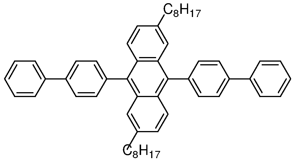
- an electronic device comprising two electrical contact layers and a photoactive layer therebetween, wherein the photoactive layer consists essentially of a compound having Formula I:
- R 1 through R 8 are the same or different at each occurrence and are selected from the group consisting of H, D, alkyl, alkoxy, aryl, aryloxy, siloxane, and silyl;
- Ar 1 and Ar 2 are the same or different and are selected from the group consisting of aryl groups;
- Ar 3 and Ar 4 are the same or different and are selected from the group consisting of H, D, and aryl groups.
- FIG. 1 includes an illustration of an exemplary organic device.
- FIG. 2 includes an illustration of an exemplary organic device.
- alkyl is intended to mean a group derived from an aliphatic hydrocarbon. In some embodiments, the alkyl group has from 1 - 20 carbon atoms.
- aryl is intended to mean a group derived from an aromatic hydrocarbon.
- aromatic compound is intended to mean an organic compound comprising at least one unsaturated cyclic group having delocalized pi electrons. The term is intended to encompass both aromatic compounds having only carbon and hydrogen atoms, and heteroaromatic compounds wherein one or more of the carbon atoms within the cyclic group has been replaced by another atom, such as nitrogen, oxygen, sulfur, or the like. In some embodiments, the aryl group has from 4-30 carbon atoms.
- charge transport when referring to a layer, material, member, or structure is intended to mean such layer, material, member, or structure facilitates migration of such charge through the thickness of such layer, material, member, or structure with relative efficiency and small loss of charge.
- Hole transport materials facilitate positive charge; electron transport materials facilitate negative charge.
- light-emitting materials may also have some charge transport properties, the term "charge transport layer, material, member, or structure” is not intended to include a layer, material, member, or structure whose primary function is light emission.
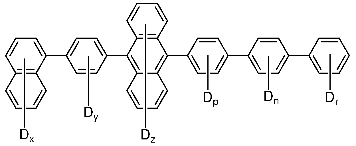
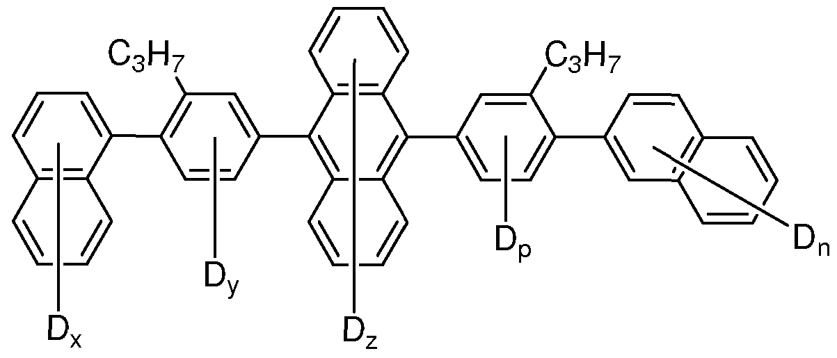
- deuterated is intended to mean that at least one H has been replaced by D.
- deuterated analog refers to a structural analog of a compound or group in which one or more available hydrogens have been replaced with deuterium. In a deuterated compound or deuterated analog, the deuterium is present in at least 100 times the natural abundance level.
- dopant is intended to mean a material, within a layer including a host material, that changes the electronic characteristic(s) or the targeted wavelength(s) of radiation emission, reception, or filtering of the layer compared to the electronic characteristic(s) or the wavelength(s) of radiation emission, reception, or filtering of the layer in the absence of such material.
- electroactive refers to a layer or a material, is intended to indicate a layer or material which electronically facilitates the operation of the device.
- electroactive materials include, but are not limited to, materials which conduct, inject, transport, or block a charge, where the charge can be either an electron or a hole, or materials which emit radiation or exhibit a change in concentration of electron-hole pairs when receiving radiation.
- inactive materials include, but are not limited to, planarization materials, insulating materials, and environmental barrier materials.
- electroactive refers to the emission of light from a material in response to an electric current passed through it.
- Electrode refers to a material that is capable of
- emission maximum is intended to mean the highest intensity of radiation emitted.
- the emission maximum has a
- fused aryl refers to an aryl group having two or more fused aromatic rings.
- hetero indicates that one or more carbon atoms has been replaced with a different atom.
- heteroatom is O, N, S, or combinations thereof.
- host material is intended to mean a material, usually in the form of a layer, to which a dopant may or may not be added.
- the host material may or may not have electronic characteristic(s) or the ability to emit, receive, or filter radiation.
- layer is used interchangeably with the term “film” and refers to a coating covering a desired area.
- the term is not limited by size.
- the area can be as large as an entire device or as small as a specific functional area such as the actual visual display, or as small as a single sub-pixel.
- Layers and films can be formed by any conventional deposition technique, including vapor deposition, liquid deposition (continuous and discontinuous techniques), and thermal transfer.
- Liquid deposition techniques include but are not limited to, spin coating, gravure coating, curtain coating, dip coating, slot-die coating, spray coating, and continuous nozzle coating, ink jet printing, gravure printing, and screen printing.
- organic electronic device or sometimes just “electronic device,” is intended to mean a device including one or more organic semiconductor layers or materials.
- photoactive refers to a material that emits light when activated by an applied voltage (such as in a light emitting diode or chemical cell) or responds to radiant energy and generates a signal with or without an applied bias voltage (such as in a photodetector).
- siloxane refers to the group (RO) 3 Si-, where R is H, D , C1 -20 alkyl, or fluoroalkyl.
- sil refers to the group -SiR 3 , where R is the same or different at each occurrence and is an alkyl group or an aryl group.
- the prefix "hetero” indicates that one or more carbon atoms have been replaced with a different atom.
- the different atom is N, O, or S.
- the prefix "fluoro” indicates that one or more hydrogen atoms have been replaced with a fluorine atom.
- substituents are D, alkyl, alkoxy, aryl, silyl, or siloxane.
- the photoactive layer comprises as least one emissive dopant material dispersed in one or more host materials.
- the photoactive layer described herein is a single component layer.
- Devices having the single component photoactive layer described herein can have improved efficiency, improved lifetime, and improved color saturation.
- the photoactive layer consists essentially of a compound having
- R 1 through R 8 are the same or different at each occurrence and are selected from the group consisting of H, D, alkyl, alkoxy, aryl, aryloxy, siloxane, and silyl;
- Ar 1 and Ar 2 are the same or different and are selected from the group consisting of aryl groups;
- Ar 3 and Ar 4 are the same or different and are selected from the group consisting of H, D, and aryl groups.
- the compound having Formula I is deuterated.
- the compound is at least 10% deuterated. By this is meant that at least 10% of the H are replaced by D.
- the compound is at least 20% deuterated; in some embodiments, at least 30% deuterated; in some embodiments, at least 40% deuterated; in some embodiments, at least 50% deuterated; in some embodiments, at least 60% deuterated; in some embodiments, at least 70% deuterated; in some embodiments, at least 80% deuterated; in some embodiments, at least 90% deuterated.
- the compounds are 100% deuterated.
- R 1 through R 8 is selected from alkyl, alkoxy, aryl, aryloxy, siloxane, and silyl, and the remainder of R 1 through R 8 are selected from H and D.
- R 2 is selected from alkyl, alkoxy, aryl, aryloxy, siloxane, and silyl.
- R 2 is selected from alkyl and aryl.
- R 2 is selected from deuterated alkyl and deuterated aryl.
- R 2 is selected from deuterated aryl having at least 10% deuteration. In some embodiments, R 2 is selected from deuterated aryl having at least 20% deuteration; in some embodiments, at least 30% deuteration; in some embodiments, at least 40% deuteration; in some embodiments, at least 50% deuteration; in some embodiments, at least 60% deuteration; in some embodiments, at least 70% deuteration; in some embodiments, at least 80% deuteration; in some embodiments, at least 90% deuteration . In some embodiments, R 2 is selected from deuterated aryl having 100% deuteration.
- At least one of Ar 1 through Ar 4 is a deuterated aryl.
- Ar 3 and Ar 4 are selected from D and deuterated aryls.
- Ar 1 and Ar 2 are selected from the group consisting of phenyl, naphthyl, phenanthryl, anthracenyl, carbazolyl, diphenylcarbazolyl, benzofuran, dibenzofuran, and deuterated analogs thereof.
- Ar 1 and Ar 2 are selected from the group consisting of phenyl, naphthyl, and deuterated analogs thereof.
- Ar 3 and Ar 4 are selected from the group consisting of phenyl, naphthyl, phenanthryl, anthracenyl,
- R 9 is the same or different at each occurrence and is selected from the group consisting of H, D, alkyl, alkoxy, siloxane and silyl, or adjacent R 9 groups may be joined together to form an aromatic ring;
- n is the same or different at each occurrence and is an integer from
- Ar 3 and Ar 4 are selected from the group consisting of phenyl, naphthyl, phenylnaphthylene, naphthylphenylene, deuterated analogs thereof, and a group having Formula III:
- m is an integer from 1 to 3.
- At least one of Ar 1 through Ar 4 is a heteroaryl group.
- the heteroaryl group is deuterated.
- the heteroaryl group is selected from carbazole, benzofuran, dibenzofuran, and deuterated analogs thereof.
- the compounds having Formula I can be prepared by known coupling and substitution reactions.
- the deuterated analog compounds can be prepared in a similar manner using deuterated precursor materials or, more generally, by treating the non-deuterated compound with deuterated solvent, such as d6-benzene, in the presence of a Lewis acid H/D exchange catalyst, such as aluminum trichloride or ethyl aluminum chloride, or acids such as CF 3 COOD, DCI, etc. Exemplary preparations are given in the Examples.
- the level of deuteration can be determined by NMR analysis and by mass spectrometry, such as Atmospheric Solids Analysis Probe Mass Spectrometry ⁇ ASAP-MS).
- Organic electronic devices that may benefit from having the photoactive layer described herein include, but are not limited to, (1 ) a device that converts electrical energy into radiation (e.g., a light-emitting diode, light emitting diode display, diode laser, luminaire, or lighting panel),
- a device that converts electrical energy into radiation e.g., a light-emitting diode, light emitting diode display, diode laser, luminaire, or lighting panel
- a device that detects a signal using an electronic process e.g., a photodetector, a photoconductive cell, a photoresistor, a photoswitch, a phototransistor, a phototube, an infrared (“IR”) detector, or a biosensors
- an electronic process e.g., a photodetector, a photoconductive cell, a photoresistor, a photoswitch, a phototransistor, a phototube, an infrared (“IR”) detector, or a biosensors
- a device that converts radiation into electrical energy e.g., a
- photovoltaic device or solar cell (4) a device that includes one or more electronic components that include one or more organic semiconductor layers (e.g., a transistor or diode), or any combination of devices in items (1 ) through (4).
- organic semiconductor layers e.g., a transistor or diode
- an organic light-emitting device comprises: an anode
- photoactive layer consists essentially of a compound having Formula I, as described above.
- the device 100 has a first electrical contact layer, an anode layer 1 10 and a second electrical contact layer, a cathode layer 160, and a photoactive layer 140 between them.
- Adjacent to the anode is a hole injection layer 120.
- Adjacent to the hole injection layer is a hole transport layer 130, comprising hole transport material.
- Adjacent to the cathode may be an electron transport layer 150, comprising an electron transport material.
- devices may use one or more additional hole injection or hole transport layers (not shown) next to the anode 1 10 and/or one or more additional electron injection or electron transport layers (not shown) next to the cathode 160.
- Layers 120 through 150 are individually and collectively referred to as the active layers.
- the photoactive layer is pixellated, as shown in FIG. 2.
- layer 140 is divided into pixel or subpixel units 141 , 142, and 143 which are repeated over the layer.
- Each of the pixel or subpixel units represents a different color.
- the subpixel units are for red, green, and blue. Although three subpixel units are shown in the figure, two or more than three may be used.
- the different layers have the following range of thicknesses: anode 1 10, 500-5000 A, in one embodiment 1000-2000 A; hole injection layer 120, 50-3000 A, in one embodiment 200-1000 A; hole transport layer 130, 50-2000 A, in one embodiment 200-1000 A;
- photoactive layer 140 10-2000 A, in one embodiment 100-1000 A; layer 150, 50-2000 A, in one embodiment 100-1000 A; cathode 160, 200-10000 A, in one embodiment 300-5000 A.
- the location of the electron-hole recombination zone in the device, and thus the emission spectrum of the device, can be affected by the relative thickness of each layer. The desired ratio of layer thicknesses will depend on the exact nature of the materials used.
- the photoactive layer 140 can be a light-emitting layer that is activated by an applied voltage (such as in a light-emitting diode or light-emitting electrochemical cell), or a layer of material that responds to radiant energy and generates a signal with or without an applied bias voltage (such as in a
- photodetector examples include photoconductive cells, photoresistors, photoswitches, phototransistors, and phototubes, and photovoltaic cells, as these terms are described in Markus, John, Electronics and Nucleonics Dictionary, 470 and 476 (McGraw-Hill, Inc. 1966).
- the photoactive layer consists essentially of a compound having
- the compound having Formula I has deep blue emission.
- deep blue is meant an emission wavelength of 420-
- the photoactive layer has an emission color with a y-coordinate less than 0.10, according to the CLE. chromaticity scale (Commission Internationale de L'Eclairage, 1931 ). In some embodiments, the y-coordinate is less than 0.7. The x-coordinate is in the range of 0.135-0.165.
- the photoactive layer can be formed by any method known to result in a layer.
- the photoactive layer is formed by liquid deposition from a liquid composition, as described below.
- the photoactive layer is formed by vapor deposition. b. Other Device Layers
- the other layers in the device can be made of any materials that are known to be useful in such layers.
- the anode 1 10 is an electrode that is particularly efficient for injecting positive charge carriers. It can be made of, for example, materials containing a metal, mixed metal, alloy, metal oxide or mixed- metal oxide, or it can be a conducting polymer, or mixtures thereof.
- Suitable metals include the Group 1 1 metals, the metals in Groups 4-6, and the Group 8-10 transition metals. If the anode is to be light- transmitting, mixed-metal oxides of Groups 12, 13 and 14 metals.
- ITO indium-tin- oxide
- IZO indium-zinc-oxide
- ATO aluminum-tin-oxide
- AZO aluminum-zinc-oxide
- ZTO zirconium-tin-oxide
- the anode 1 10 can also comprise an organic material such as polyaniline as described in “Flexible light-emitting diodes made from soluble conducting polymer,” Nature vol. 357, pp 477-479 (1 1 June 1992).
- the anode comprises a fluorinated acid polymer and conductive nanoparticles.
- a fluorinated acid polymer and conductive nanoparticles.
- Such materials have been described in, for example, US Patent 7,749,407.
- At least one of the anode and cathode is desirably at least partially transparent to allow the generated light to be observed.
- the hole injection layer 120 comprises hole injection material and may have one or more functions in an organic electronic device, including but not limited to, planarization of the underlying layer, charge transport and/or charge injection properties, scavenging of impurities such as oxygen or metal ions, and other aspects to facilitate or to improve the performance of the organic electronic device.
- Hole injection materials may be polymers, oligomers, or small molecules. They may be vapour deposited or deposited from liquids which may be in the form of solutions, dispersions, suspensions, emulsions, colloidal mixtures, or other compositions.
- the hole injection layer can be formed with polymeric materials, such as polyaniline (PANI) or polyethylenedioxythiophene (PEDOT), which are often doped with protonic acids.
- the protonic acids can be, for example, poly(styrenesulfonic acid), poly(2-acrylamido-2-methyl-1 - propanesulfonic acid), and the like.
- the hole injection layer can comprise charge transfer compounds, and the like, such as copper phthalocyanine and the tetrathiafulvalene- tetracyanoquinodimethane system (TTF-TCNQ).
- charge transfer compounds such as copper phthalocyanine and the tetrathiafulvalene- tetracyanoquinodimethane system (TTF-TCNQ).
- the hole injection layer comprises at least one electrically conductive polymer and at least one fluorinated acid polymer.
- electrically conductive polymer and at least one fluorinated acid polymer.
- the hole injection layer comprises a fluorinated acid polymer and conductive nanoparticles.
- a fluorinated acid polymer and conductive nanoparticles.
- hole transport materials for layer 130 have been summarized for example, in Kirk-Othmer Encyclopedia of Chemical Technology, Fourth Edition, Vol. 18, p. 837-860, 1996, by Y. Wang. Both hole transporting molecules and polymers can be used. Commonly used hole transporting molecules are: N,N'-diphenyl-N,N'-bis(3-methylphenyl)- [1 ,1 '-biphenyl]-4,4'-diamine (TPD), 1 ,1 -bis[(di-4-tolylamino)
- TAPC phenyl]cyclohexane
- EPD phenyl]cyclohexane
- PDA tetrakis-(3- methylphenyl)-N,N,N',N'-2,5-phenylenediamine
- TPS p-(diethylamino)benzaldehyde
- DEH diphenylhydrazone
- TPA triphenylamine
- MPMP bis[4-(N,N- diethylamino)-2-methylphenyl](4-methylphenyl)methane
- hole transporting polymers are polyvinylcarbazole, (phenylmethyl)- polysilane, and polyaniline. It is also possible to obtain hole transporting polymers by doping hole transporting molecules such as those mentioned above into polymers such as polystyrene and polycarbonate. In some cases, triarylamine polymers are used, especially triarylamine-fluorene copolymers. In some cases, the polymers and copolymers are
- the hole transport layer further comprises a p-dopant.
- the hole transport layer is doped with a p-dopant.
- p-dopants include, but are not limited to, tetrafluorotetracyanoquinodimethane (F4-TCNQ) and perylene- 3,4,9,10-tetracarboxylic-3,4,9,10-dianhydride (PTCDA).
- electron transport materials which can be used for layer 150 include, but are not limited to, metal chelated oxinoid
- metal quinolate derivatives such as tris(8- hydroxyquinolato)aluminum (AIQ), bis(2-methyl-8-quinolinolato)(p- phenylphenolato) aluminum (BAIq), tetrakis-(8-hydroxyquinolato)hafnium (HfQ) and tetrakis-(8-hydroxyquinolato)zirconium (ZrQ); and azole compounds such as 2- (4-biphenylyl)-5-(4-t-butylphenyl)-1 ,3,4-oxadiazole (PBD), 3-(4-biphenylyl)-4-phenyl-5-(4-t-butylphenyl)-1 ,2,4-triazole (TAZ), and 1 ,3,5-tri(phenyl-2-benzimidazole)benzene (TPBI); quinoxaline derivatives such as 2,3-bis(4-fluorophenyl)quinoxaline; phenan
- the electron transport layer further comprises an n-dopant.
- N-dopant materials are well known.
- the cathode 160 is an electrode that is particularly efficient for injecting electrons or negative charge carriers.
- the cathode can be any metal or nonmetal having a lower work function than the anode.
- Materials for the cathode can be selected from alkali metals of Group 1 (e.g., Li, Cs), the Group 2 (alkaline earth) metals, the Group 12 metals, including the rare earth elements and lanthanides, and the actinides. Materials such as aluminum, indium, calcium, barium, samarium and magnesium, as well as combinations, can be used.
- Li-containing organometallic compounds, LiF, Li 2 O, Cs-containing organometallic compounds, CsF, Cs 2 O, and Cs 2 CO 3 can also be deposited between the organic layer and the cathode layer to lower the operating voltage.
- This layer may be referred to as an electron injection layer.
- anode 1 10 and hole injection layer 120 there can be a layer (not shown) between the anode 1 10 and hole injection layer 120 to control the amount of positive charge injected and/or to provide band-gap matching of the layers, or to function as a protective layer.
- Layers that are known in the art can be used, such as copper phthalocyanine, silicon oxy-nitride, fluorocarbons, silanes, or an ultra-thin layer of a metal, such as Pt.
- some or all of anode layer 1 10, active layers 120, 130, 140, and 150, or cathode layer 160 can be surface-treated to increase charge carrier transport efficiency.
- the choice of materials for each of the component layers is preferably determined by balancing the positive and negative charges in the emitter layer to provide a device with high electroluminescence efficiency.
- each functional layer can be made up of more than one layer.
- the device layers can be formed by any deposition technique, or combinations of techniques, including vapor deposition, liquid deposition, and thermal transfer. Substrates such as glass, plastics, and metals can be used. Conventional vapor deposition techniques can be used, such as thermal evaporation, chemical vapor deposition, and the like.
- the organic layers can be applied from solutions or dispersions in suitable solvents, using conventional coating or printing techniques, including but not limited to spin-coating, dip-coating, roll-to-roll techniques, ink-jet printing, continuous nozzle printing, screen-printing, gravure printing and the like.
- the process for making an organic light- emitting device comprises:
- a photoactive layer by depositing a first liquid composition consisting essentially of (a) a compound having Formula I and
- liquid composition is intended to include a liquid medium in which one or more materials are dissolved to form a solution, a liquid medium in which one or more materials are dispersed to form a
- dispersion or a liquid medium in which one or more materials are suspended to form a suspension or an emulsion.
- the process further comprises:
- the hole transport layer is formed by depositing a second liquid composition comprising a hole transport material in a second liquid medium.
- the process further comprises:
- the hole transport layer is formed by depositing a third liquid composition comprising a hole transport material in a third liquid medium.
- the process further comprises:
- the electron transport layer is formed by depositing a fourth liquid composition comprising an electron transport material in a fourth liquid medium.
- the process for making an organic light- emitting device comprises: providing a substrate having a patterned anode thereon;
- transport layer is formed by depositing a second liquid composition comprising a hole transport material in a second liquid medium
- the hole transport layer is formed by depositing a second liquid composition comprising a hole transport material in a second liquid medium
- a first liquid composition consisting essentially of (a) a compound having Formula I and (b) a liquid medium; and forming a cathode overall.
- the term "over" indicates the relative position of a layer, but does not necessarily mean that there is direct contact.
- a second layer that is over a first layer may be directly on and in contact with the first layer, or the second layer may be on one of one or more intervening layers between the first and second layers.
- any known liquid deposition technique or combination of techniques can be used to form the photoactive layer, including continuous and discontinuous techniques.
- liquid deposition techniques include, but are not limited to spin coating, gravure coating, curtain coating, dip coating, slot-die coating, spray coating, continuous nozzle printing, ink jet printing, gravure printing, and screen printing.
- the photoactive layer is formed in a pattern by a method selected from continuous nozzle printing and ink jet printing.
- the nozzle printing can be considered a continuous technique, a pattern can be formed by placing the nozzle over only the desired areas for layer formation. For example, patterns of continuous rows can be formed.
- a suitable liquid medium for a particular photoactive composition to be deposited can be readily determined by one skilled in the art.
- the compounds be dissolved in nonaqueous solvents.
- non-aqueous solvents can be relatively polar, such as Ci to C 2 o alcohols, ethers, and acid esters, or can be relatively non-polar such as Ci to Ci 2 alkanes or aromatics such as toluene, xylenes, trifluorotoluene and the like.
- Another suitable liquid for use in making the liquid composition, either as a solution or dispersion as described herein, comprising the new compound includes, but not limited to, a chlorinated hydrocarbon (such as methylene chloride, chloroform, chlorobenzene), an aromatic hydrocarbon (such as a substituted or non- substituted toluene or xylenes, including trifluorotoluene), a polar solvent (such as tetrahydrofuran (THF), N-methyl pyrrolidone (NMP)), an ester (such as ethylacetate), an alcohol (such as isopropanol), a ketone (such as cyclopentatone), aromatic esters, aromatic ethers, or any mixture thereof.
- a chlorinated hydrocarbon such as methylene chloride, chloroform, chlorobenzene
- an aromatic hydrocarbon such as a substituted or non- substituted toluene or xylenes, including trifluorotoluen
- the material is dried to form a layer. Any conventional drying technique can be used, including heating, vacuum, and combinations thereof.
- the device is fabricated by liquid deposition of the hole injection layer, the hole transport layer, and the photoactive layer, and by vapor deposition of the anode, the electron transport layer, the electron injection layer and the cathode.
- This example illustrates the preparation of Compound E1 .
- This compound can be prepared according to the following scheme:
- the red oil was taken up in DCM, absorbed onto silica gel and dried down. It was applied to the top of a pad of silica and eluted with several liters of neat hexane followed by 3L of 95/5 hexane/DCM.
- naphthalen-1 -yl-1 -boronic 14.2g, 82.6mmol
- acid 1 -bromo-2-iodobenzene (25.8g, 91 .2 mmol)
- reaction mixture was purged with nitrogen and degassed water (120 ml_) was added by syringe. A condensor was equipped and the reaction was refluxed for 15 hours. TLC was performed indicating the reaction was complete. The reaction mixture was cooled to room
- the product was further purified as described in published U.S. patent application 2008-0138655, to achieve an HPLC purity of at least 99.9% and an impurity absorbance no greater than 0.01 .
- the product was further purified as described in published U.S. patent application 2008-0138655, to achieve an HPLC purity of at least 99.9% and an impurity absorbance no greater than 0.01 .
- the material was determined to have the same level of purity as Intermediate 1 , from above.
- the structure was confimred by 1 H NMR, 13 C NMR, 2 D NMR and 1 H- 13 C HSQC (Heteronuclear Single Quantum Coherence).
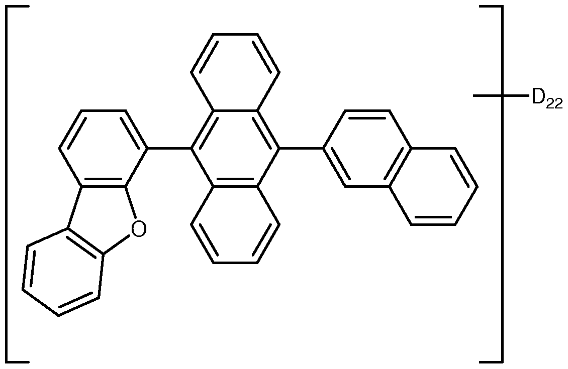
- This example illustrates the preparation of a host compound, Host-1 shown below.
- the reaction was stirred and refluxed in an oil bath at 95 °C under nitrogen for 18 hour. After cooling to ambient temperature, some solid was seen formed and it was collected by filtration. The organic phase was separated, washed with water (60 ml_), diluted HCI (10%, 60 ml_) and saturated brine (60 ml_) and dried with MgSO 4 . The solution was filtered through a Silica gel plug and the solvent was removed by rotary
- HT-1 may contain up to 20% of a second isomer, where the asterisk indicates the point of attachment:
- HT-2 may contain up to 20% of a second isomer
- HIJ-1 is an electrically conductive polymer doped with a polymeric
- ET-1 is a phenanthroline derivative.
- ET-2 is a metal quinolate compound.
- Device Example 1 and Comparative Examples A-B are a metal quinolate compound.
- Compound E15 was present as a dopant in a host compound.
- the devices had the following structure on a glass substrate:
- anode Indium Tin Oxide (ITO), 50 nm
- hole injection layer HIJ-1 (50 nm).
- photoactive layer is shown in Table 1 (40 nm).
- electron injection layer/cathode CsF/AI (0.7(as deposited)/100 nm).
- OLED devices were fabricated by a combination of solution processing and thermal evaporation techniques.
- Patterned indium tin oxide (ITO) coated glass substrates from Thin Film Devices, Inc were used. These ITO substrates are based on Corning 1737 glass coated with ITO having a sheet resistance of 30 ohms/square and 80% light transmission.
- the patterned ITO substrates were cleaned ultrasonically in aqueous detergent solution and rinsed with distilled water.
- the patterned ITO was subsequently cleaned ultrasonically in acetone, rinsed with isopropanol, and dried in a stream of nitrogen.
- ITO substrates were treated with UV ozone for 10 minutes.
- an aqueous dispersion of HIJ-1 was spin-coated over the ITO surface and heated to remove solvent.
- the substrates were then spin-coated with a solution of a hole transport material, and then heated to remove solvent.
- the substrates were spin-coated with a solution of the photoactive layer material(s) in methyl benzoate and heated to remove solvent.
- the substrates were masked and placed in a vacuum chamber.
- the electron transport layer was deposited by thermal evaporation, followed by a layer of CsF.
- Masks were then changed in vacuo and a layer of Al was deposited by thermal evaporation.
- the chamber was vented, and the devices were encapsulated using a glass lid, dessicant, and UV curable epoxy.
- the OLED samples were characterized by measuring their (1 ) current-voltage (l-V) curves, (2) electroluminescence radiance versus voltage, and (3) electroluminescence spectra versus voltage. All three measurements were performed at the same time and controlled by a computer. The current efficiency of the device at a certain voltage is determined by dividing the electroluminescence radiance of the LED by the current density needed to run the device. The unit is a cd/A. The results are given in Table 2. Table 1 . Device Materials
- Photoactive layer ratio is weight ratio
- C.E. current efficiency
- V voltage at 150 mA/cm 2
- P.E. power efficiency
- CIEX and CIEY are the x- and y-color coordinates according to the CLE. chromaticity scale (Commission Internationale de L'Eclairage, 1 931 ); T50 is the time in hours for a device to reach one-half the initial luminance.
- the devices had the following structure on a glass substrate:
- anode Indium Tin Oxide (ITO), 50 nm
- hole injection layer HIJ-1 (52 nm).
- photoactive layer E15 (40 nm).
- OLED devices were fabricated and tested as described in Device Example 1 . The results are given in Table 4.
- C.E. current efficiency
- V voltage at 150 mA/cm 2
- P.E. power efficiency
- CIEX and CIEY are the x- and y-color coordinates according to the CLE. chromaticity scale (Commission Internationale de L'Eclairage, 1 931 ); T50 is the time in hours for a device to reach one-half the initial luminance.
Landscapes
- Chemical & Material Sciences (AREA)
- Engineering & Computer Science (AREA)
- Materials Engineering (AREA)
- Physics & Mathematics (AREA)
- Spectroscopy & Molecular Physics (AREA)
- Organic Chemistry (AREA)
- Electroluminescent Light Sources (AREA)
- Light Receiving Elements (AREA)
Abstract
Description


Claims


Priority Applications (5)
| Application Number | Priority Date | Filing Date | Title |
|---|---|---|---|
| KR1020137029283A KR20140039187A (en) | 2011-04-08 | 2012-04-09 | Electronic device |
| CN201280014337.7A CN103562343B (en) | 2011-04-08 | 2012-04-09 | Electronic installation |
| EP12865370.6A EP2694620A4 (en) | 2011-04-08 | 2012-04-09 | Electronic device |
| US14/005,021 US20140001459A1 (en) | 2011-04-08 | 2012-04-09 | Electronic device |
| JP2014504063A JP5758045B2 (en) | 2011-04-08 | 2012-04-09 | Electronic devices |
Applications Claiming Priority (2)
| Application Number | Priority Date | Filing Date | Title |
|---|---|---|---|
| US201161473323P | 2011-04-08 | 2011-04-08 | |
| US61/473,323 | 2011-04-08 |
Publications (2)
| Publication Number | Publication Date |
|---|---|
| WO2013106041A2 true WO2013106041A2 (en) | 2013-07-18 |
| WO2013106041A3 WO2013106041A3 (en) | 2013-10-17 |
Family
ID=48094282
Family Applications (1)
| Application Number | Title | Priority Date | Filing Date |
|---|---|---|---|
| PCT/US2012/032681 WO2013106041A2 (en) | 2011-04-08 | 2012-04-09 | Electronic device |
Country Status (7)
| Country | Link |
|---|---|
| US (1) | US20140001459A1 (en) |
| EP (1) | EP2694620A4 (en) |
| JP (1) | JP5758045B2 (en) |
| KR (1) | KR20140039187A (en) |
| CN (1) | CN103562343B (en) |
| TW (1) | TW201245408A (en) |
| WO (1) | WO2013106041A2 (en) |
Cited By (5)
| Publication number | Priority date | Publication date | Assignee | Title |
|---|---|---|---|---|
| KR20150062241A (en) * | 2013-11-28 | 2015-06-08 | 엘지디스플레이 주식회사 | Compound and organic light emitting device comprising the same |
| WO2015089028A1 (en) * | 2013-12-11 | 2015-06-18 | E. I. Du Pont De Nemours And Company | Photoactive compositions for electronic applications |
| JP2015203027A (en) * | 2014-04-16 | 2015-11-16 | Jnc株式会社 | Anthracene derivative and organic el element |
| KR20190060533A (en) * | 2017-11-24 | 2019-06-03 | 주식회사 엘지화학 | Compound, coating composition comprising the same, organic light emitting device comprising the same and method of manufacturing thereof |
| KR20210075088A (en) | 2018-10-09 | 2021-06-22 | 이데미쓰 고산 가부시키가이샤 | Novel compounds, organic electroluminescent devices, electronic devices |
Families Citing this family (7)
| Publication number | Priority date | Publication date | Assignee | Title |
|---|---|---|---|---|
| CN110317186B (en) * | 2018-03-28 | 2023-07-07 | 乐金显示有限公司 | Novel organic compound and organic electroluminescent device comprising the same |
| KR102136806B1 (en) * | 2018-03-28 | 2020-07-23 | 엘지디스플레이 주식회사 | Novel organic compounds and an organic electroluminescent device comprising the same |
| KR102064949B1 (en) * | 2018-07-24 | 2020-01-10 | 머티어리얼사이언스 주식회사 | Organic compound and organic electroluminescent device comprising the same |
| US20200111962A1 (en) | 2018-10-03 | 2020-04-09 | Idemitsu Kosan Co., Ltd. | Organic electroluminescence device and electronic apparatus provided with the same |
| US10763444B2 (en) | 2018-10-09 | 2020-09-01 | Idemitsu Kosan Co., Ltd. | Organic electroluminescence device and electronic apparatus provided with the same |
| US11864461B2 (en) * | 2018-10-16 | 2024-01-02 | Lg Chem, Ltd. | Organic compound and organic light-emitting device comprising same |
| KR102305649B1 (en) | 2018-10-26 | 2021-09-29 | 롬엔드하스전자재료코리아유한회사 | Organic electroluminescent compound and organic electroluminescent device comprising the same |
Citations (10)
| Publication number | Priority date | Publication date | Assignee | Title |
|---|---|---|---|---|
| US20010056173A1 (en) | 2000-05-17 | 2001-12-27 | Jae-Young Jeon | Method for preparing polyester resin copolymerized with 1,4-cyclohexanedimethanol |
| EP1333078A2 (en) | 2002-01-31 | 2003-08-06 | tesa AG | Adhesive packaging tape |
| US20040102577A1 (en) | 2002-09-24 | 2004-05-27 | Che-Hsiung Hsu | Water dispersible polythiophenes made with polymeric acid colloids |
| US20040127637A1 (en) | 2002-09-24 | 2004-07-01 | Che-Hsiung Hsu | Water dispersible polyanilines made with polymeric acid colloids for electronics applications |
| US20050205860A1 (en) | 2004-03-17 | 2005-09-22 | Che-Hsiung Hsu | Water dispersible polypyrroles made with polymeric acid colloids for electronics applications |
| US20080067473A1 (en) | 2006-06-05 | 2008-03-20 | Walker Dennis D | Liquid composition for deposition of organic active materials |
| US20080138655A1 (en) | 2006-11-13 | 2008-06-12 | Daniel David Lecloux | Organic electronic device |
| WO2009018009A1 (en) | 2007-07-27 | 2009-02-05 | E. I. Du Pont De Nemours And Company | Aqueous dispersions of electrically conducting polymers containing inorganic nanoparticles |
| WO2009067419A1 (en) | 2007-11-19 | 2009-05-28 | E. I. Du Pont De Nemours And Company | Electroactive materials |
| US7749407B2 (en) | 2005-06-28 | 2010-07-06 | E.I. Du Pont De Nemours And Company | High work function transparent conductors |
Family Cites Families (20)
| Publication number | Priority date | Publication date | Assignee | Title |
|---|---|---|---|---|
| US5077142A (en) * | 1989-04-20 | 1991-12-31 | Ricoh Company, Ltd. | Electroluminescent devices |
| JP3816969B2 (en) * | 1994-04-26 | 2006-08-30 | Tdk株式会社 | Organic EL device |
| JP3769934B2 (en) * | 1998-05-20 | 2006-04-26 | 凸版印刷株式会社 | Organic thin film EL device |
| US6465115B2 (en) * | 1998-12-09 | 2002-10-15 | Eastman Kodak Company | Electroluminescent device with anthracene derivatives hole transport layer |
| US7053255B2 (en) * | 2000-11-08 | 2006-05-30 | Idemitsu Kosan Co., Ltd. | Substituted diphenylanthracene compounds for organic electroluminescence devices |
| US6579630B2 (en) * | 2000-12-07 | 2003-06-17 | Canon Kabushiki Kaisha | Deuterated semiconducting organic compounds used for opto-electronic devices |
| EP2145937B2 (en) * | 2002-08-23 | 2016-03-02 | Idemitsu Kosan Co., Ltd. | Organic electroluminescence device and anthracene derivative |
| AU2002347158A1 (en) * | 2002-12-06 | 2004-06-30 | Shuang Xie | Electroluminescent devices |
| CN1914293B (en) * | 2003-12-19 | 2010-12-01 | 出光兴产株式会社 | Light-emitting material for organic electroluminescent device, organic electroluminescent device using same, and material for organic electroluminescent device |
| US7252893B2 (en) * | 2004-02-17 | 2007-08-07 | Eastman Kodak Company | Anthracene derivative host having ranges of dopants |
| JP4788202B2 (en) * | 2004-07-09 | 2011-10-05 | Jnc株式会社 | Luminescent material and organic electroluminescent device using the same |
| JP2008526768A (en) * | 2004-12-30 | 2008-07-24 | イー・アイ・デュポン・ドウ・ヌムール・アンド・カンパニー | Organometallic complex |
| US20070134512A1 (en) * | 2005-12-13 | 2007-06-14 | Eastman Kodak Company | Electroluminescent device containing an anthracene derivative |
| KR101068224B1 (en) * | 2008-02-05 | 2011-09-28 | 에스에프씨 주식회사 | Anthracene derivatives and organoelectroluminescent device including the same |
| US8263973B2 (en) * | 2008-12-19 | 2012-09-11 | E I Du Pont De Nemours And Company | Anthracene compounds for luminescent applications |
| CN102341475A (en) * | 2008-12-22 | 2012-02-01 | E.I.内穆尔杜邦公司 | Electronic devices having long lifetime |
| US8759818B2 (en) * | 2009-02-27 | 2014-06-24 | E I Du Pont De Nemours And Company | Deuterated compounds for electronic applications |
| KR101427457B1 (en) * | 2009-02-27 | 2014-08-08 | 이 아이 듀폰 디 네모아 앤드 캄파니 | Deuterated compounds for electronic applications |
| KR101616691B1 (en) * | 2009-09-09 | 2016-05-02 | 에스에프씨 주식회사 | Organic electroluminescent device |
| KR101191644B1 (en) * | 2010-05-18 | 2012-10-17 | 삼성디스플레이 주식회사 | Organic material and organic light emitting device using the same |
-
2012
- 2012-04-06 TW TW101112181A patent/TW201245408A/en unknown
- 2012-04-09 US US14/005,021 patent/US20140001459A1/en not_active Abandoned
- 2012-04-09 JP JP2014504063A patent/JP5758045B2/en active Active
- 2012-04-09 CN CN201280014337.7A patent/CN103562343B/en active Active
- 2012-04-09 WO PCT/US2012/032681 patent/WO2013106041A2/en active Application Filing
- 2012-04-09 KR KR1020137029283A patent/KR20140039187A/en active Search and Examination
- 2012-04-09 EP EP12865370.6A patent/EP2694620A4/en not_active Withdrawn
Patent Citations (10)
| Publication number | Priority date | Publication date | Assignee | Title |
|---|---|---|---|---|
| US20010056173A1 (en) | 2000-05-17 | 2001-12-27 | Jae-Young Jeon | Method for preparing polyester resin copolymerized with 1,4-cyclohexanedimethanol |
| EP1333078A2 (en) | 2002-01-31 | 2003-08-06 | tesa AG | Adhesive packaging tape |
| US20040102577A1 (en) | 2002-09-24 | 2004-05-27 | Che-Hsiung Hsu | Water dispersible polythiophenes made with polymeric acid colloids |
| US20040127637A1 (en) | 2002-09-24 | 2004-07-01 | Che-Hsiung Hsu | Water dispersible polyanilines made with polymeric acid colloids for electronics applications |
| US20050205860A1 (en) | 2004-03-17 | 2005-09-22 | Che-Hsiung Hsu | Water dispersible polypyrroles made with polymeric acid colloids for electronics applications |
| US7749407B2 (en) | 2005-06-28 | 2010-07-06 | E.I. Du Pont De Nemours And Company | High work function transparent conductors |
| US20080067473A1 (en) | 2006-06-05 | 2008-03-20 | Walker Dennis D | Liquid composition for deposition of organic active materials |
| US20080138655A1 (en) | 2006-11-13 | 2008-06-12 | Daniel David Lecloux | Organic electronic device |
| WO2009018009A1 (en) | 2007-07-27 | 2009-02-05 | E. I. Du Pont De Nemours And Company | Aqueous dispersions of electrically conducting polymers containing inorganic nanoparticles |
| WO2009067419A1 (en) | 2007-11-19 | 2009-05-28 | E. I. Du Pont De Nemours And Company | Electroactive materials |
Non-Patent Citations (5)
| Title |
|---|
| "CRC Handbook of Chemistry and Physics", 2000 |
| "Flexible light-emitting diodes made from soluble conducting polymer", NATURE, vol. 357, 11 June 1992 (1992-06-11), pages 477 - 479 |
| MARKUS, JOHN: "Electronics and Nucleonics Dictionary", 1966, MCGRAW-HILL, INC., pages: 47,476 |
| See also references of EP2694620A4 |
| Y. WANG: "Kirk-Othmer Encyclopedia of Chemical Technology", vol. 18, 1996, pages: 837 - 860 |
Cited By (7)
| Publication number | Priority date | Publication date | Assignee | Title |
|---|---|---|---|---|
| KR20150062241A (en) * | 2013-11-28 | 2015-06-08 | 엘지디스플레이 주식회사 | Compound and organic light emitting device comprising the same |
| KR102228323B1 (en) * | 2013-11-28 | 2021-03-16 | 엘지디스플레이 주식회사 | Compound and organic light emitting device comprising the same |
| WO2015089028A1 (en) * | 2013-12-11 | 2015-06-18 | E. I. Du Pont De Nemours And Company | Photoactive compositions for electronic applications |
| JP2015203027A (en) * | 2014-04-16 | 2015-11-16 | Jnc株式会社 | Anthracene derivative and organic el element |
| KR20190060533A (en) * | 2017-11-24 | 2019-06-03 | 주식회사 엘지화학 | Compound, coating composition comprising the same, organic light emitting device comprising the same and method of manufacturing thereof |
| KR102393502B1 (en) * | 2017-11-24 | 2022-05-02 | 주식회사 엘지화학 | Compound, coating composition comprising the same, organic light emitting device comprising the same and method of manufacturing thereof |
| KR20210075088A (en) | 2018-10-09 | 2021-06-22 | 이데미쓰 고산 가부시키가이샤 | Novel compounds, organic electroluminescent devices, electronic devices |
Also Published As
| Publication number | Publication date |
|---|---|
| JP2014515188A (en) | 2014-06-26 |
| EP2694620A4 (en) | 2014-12-31 |
| CN103562343A (en) | 2014-02-05 |
| KR20140039187A (en) | 2014-04-01 |
| US20140001459A1 (en) | 2014-01-02 |
| CN103562343B (en) | 2016-08-10 |
| WO2013106041A3 (en) | 2013-10-17 |
| TW201245408A (en) | 2012-11-16 |
| JP5758045B2 (en) | 2015-08-05 |
| EP2694620A2 (en) | 2014-02-12 |
Similar Documents
| Publication | Publication Date | Title |
|---|---|---|
| KR101755067B1 (en) | Electroactive materials | |
| KR101884479B1 (en) | Electroactive composition and electronic device made with the composition | |
| KR101427457B1 (en) | Deuterated compounds for electronic applications | |
| JP5758045B2 (en) | Electronic devices | |
| KR102158326B1 (en) | Electroactive compositions for electronic applications | |
| JP6204453B2 (en) | Green light emitting material | |
| KR20130130788A (en) | Triazine derivatives for electronic applications | |
| KR102283558B1 (en) | Photoactive composition | |
| US20120187383A1 (en) | Electroactive compound and composition and electronic device made with the composition | |
| JP6445551B2 (en) | Blue light emitting compound | |
| KR102238701B1 (en) | Electroactive material | |
| KR102290837B1 (en) | Luminescent compounds | |
| KR20140040686A (en) | Electroactive 1,7- and 4,10- diazachrysene derivatives and devices made with such materials | |
| WO2017027333A1 (en) | Hole transport materials | |
| WO2016064671A2 (en) | Blue luminescent compounds | |
| WO2014176159A1 (en) | Blue luminescent compounds | |
| EP2652084B1 (en) | Electroactive materials | |
| WO2016191171A1 (en) | Electroactive materials | |
| WO2016010746A1 (en) | Hole transport materials | |
| CN114080392A (en) | Electroactive compounds |
Legal Events
| Date | Code | Title | Description |
|---|---|---|---|
| REEP | Request for entry into the european phase |
Ref document number: 2012865370 Country of ref document: EP |
|
| WWE | Wipo information: entry into national phase |
Ref document number: 2012865370 Country of ref document: EP |
|
| 121 | Ep: the epo has been informed by wipo that ep was designated in this application |
Ref document number: 12865370 Country of ref document: EP Kind code of ref document: A2 |
|
| WWE | Wipo information: entry into national phase |
Ref document number: 14005021 Country of ref document: US |
|
| ENP | Entry into the national phase |
Ref document number: 2014504063 Country of ref document: JP Kind code of ref document: A |
|
| ENP | Entry into the national phase |
Ref document number: 20137029283 Country of ref document: KR Kind code of ref document: A |