WO2013105669A1 - Applicator implement - Google Patents
Applicator implement Download PDFInfo
- Publication number
- WO2013105669A1 WO2013105669A1 PCT/JP2013/050572 JP2013050572W WO2013105669A1 WO 2013105669 A1 WO2013105669 A1 WO 2013105669A1 JP 2013050572 W JP2013050572 W JP 2013050572W WO 2013105669 A1 WO2013105669 A1 WO 2013105669A1
- Authority
- WO
- WIPO (PCT)
- Prior art keywords
- application
- applicator
- cover
- slit
- nail
- Prior art date
Links
Images


Classifications
-
- A—HUMAN NECESSITIES
- A45—HAND OR TRAVELLING ARTICLES
- A45D—HAIRDRESSING OR SHAVING EQUIPMENT; EQUIPMENT FOR COSMETICS OR COSMETIC TREATMENTS, e.g. FOR MANICURING OR PEDICURING
- A45D29/00—Manicuring or pedicuring implements
- A45D29/004—Masking devices for applying polish to the finger nails
-
- A—HUMAN NECESSITIES
- A45—HAND OR TRAVELLING ARTICLES
- A45D—HAIRDRESSING OR SHAVING EQUIPMENT; EQUIPMENT FOR COSMETICS OR COSMETIC TREATMENTS, e.g. FOR MANICURING OR PEDICURING
- A45D34/00—Containers or accessories specially adapted for handling liquid toiletry or cosmetic substances, e.g. perfumes
- A45D34/04—Appliances specially adapted for applying liquid, e.g. using roller or ball
-
- A—HUMAN NECESSITIES
- A45—HAND OR TRAVELLING ARTICLES
- A45D—HAIRDRESSING OR SHAVING EQUIPMENT; EQUIPMENT FOR COSMETICS OR COSMETIC TREATMENTS, e.g. FOR MANICURING OR PEDICURING
- A45D29/00—Manicuring or pedicuring implements
- A45D2029/002—French manicure
Definitions
- the present invention particularly relates to a French nail (applying a coating solution to the front end of a nail) in the nail art field where nail art is applied around the toe, which is associated with makeup of the fingertips of the hand.
- the present invention relates to an applicator that can be applied with a constant width following the shape of the front end of the nail and can draw a line without depending on the dominant hand or experience, for the purpose of easily and accurately applying the liquid from the end to the front end.
- An example of an applicator that takes out the application liquid in the container with an application body and applies it to a target location is a nail polish product that applies a nail polish liquid.
- a nail polish is applied around the toes that comes with the makeup of the fingertips.
- This French nail is a general example when applied to the nail by an individual.
- the base solution is applied to the entire surface of the nail immediately before applying the French nail, and after the French nail is applied, a protective coating solution is further applied. . Since many processes are required, there is a demand for a coating method that finishes as cleanly and simply as possible.
- This exclusive brush has a brush shape that simulates the round shape of the nail, and the front direction has a U-shape that simulates the front surface of the nail.
- a French nail operation can be performed by applying it to the nail as it is in the shape of a dedicated brush (see, for example, Japanese Patent Application Laid-Open No. 2004-8826: Patent Document 2).
- Patent Document 1 applies the front end of the nail with a brush or pen core in a normal freehand, but because it is a freehand, its experience and technology are very involved, Among them, positioning was not stable and application was difficult. In addition, even if experience and technology improved, the finish itself was often not satisfactory.
- Patent Document 2 is difficult to determine the position to the application destination as described above, and it takes time to learn. The same applies to the application to the dominant hand. Since the brush shape is also fixed in a round shape, it is not suitable for flat toes. Furthermore, since the U-shaped in a plan view, the coating solution hangs down and the coating solution at the center of the nail tends to become thin.
- the applicator disclosed in Patent Document 3 can stably apply to the nails of the left and right hands without affecting the dominant hand, but the position is fixed by pressing against the toes, but if the pressing is strong, the position is fixed. There were many deviations. In particular, at the end of the nail, the application part tends to be partially detached from the fixed part and dirty the nail. Further, since the pen core is pressed against the toe every time it is used, there is a problem in maintaining the pen core shape (durability).
- the applicator disclosed in Patent Document 4 has a tendency to deviate in appearance because the seal is peeled off from the mount with tweezers or the like and set in the vertical and horizontal directions. Therefore, it took time to learn. Further, if the sealing surface is soiled, there is a problem that the adhesion is weakened and easily peeled off. In addition, a thickness step of the seal inevitably occurs between the nail and the seal, which is uncomfortable. Furthermore, it is very fragile compared to the nails, so it is easily damaged and inferior in durability. Although it was a seal, it was expensive.
- an object of the present invention is to provide an applicator that can be prepared and applied in a short time regardless of the curved surface of the nail, that is, satisfying the finish of an individual French nail operation. It is another object of the present invention to provide an applicator that is low in cost and can avoid soiling the nails.
- the present invention provides an applicator that allows the application liquid to be applied to an object by contacting the application portion of the application body impregnated with the application liquid.
- An application body having a flat application surface formed on the application part; It is attached to the application body and covers the application part, and includes an application cover in which a slit communicating from the outside to the inside is formed, With the application cover covering the application part, the application surface of the application part is positioned in the slit, and the object is inserted into the predetermined part of the object by the application surface by inserting the object through the slit.
- An applicator characterized in that application is possible.
- the present invention can be applied easily and stably. Further, by forming the application surface of the application part on, for example, a U-shaped inner surface, a nail can be inserted, and a stable line can be obtained simply by moving the application part in the direction in which the nail is desired to be applied.
- the application body to be applied to the object is a fiber body processed with fibers and resin.
- the application body has a flat application surface formed along the axial direction of the application body at a front end, and the application liquid is applied to the toe by the application surface through the slit.
- the applicator is a French nail applicator configured so that it can be applied. Therefore, the nail shape can be positioned by processing a U-shape that is the limit of nail entry into the fiber body that is the application body and inserting the nail tip to the limit of entry.
- the application part and the nail are fixed, and the tip of the nail serving as the application surface hits the application part of the application body, the liquid is applied, and a stable line can be obtained simply by moving the application part or the nail in the desired direction.
- the width of application to the toe can be changed by changing the depth of the U-shaped dent at the front end of the application body.
- the width can be made appropriate regardless of the thickness of the toe.
- the upper and lower surfaces of the U-shape at the front end of the application body are straight lines (the surface itself is a flat surface) or a curve of R10 or more (the cross section is a flat surface) when viewed from the front of the application surface, and there is a difference in curved surface between each finger. However, it can be applied smoothly.
- the application body has a flat application surface formed along the axial direction of the application body at a front end portion, and a coating liquid is applied to the toe tip by passing the toe through the slit of the application cover.
- the applicator for French nail is preferably configured to be able to be applied with a width.
- the application cover is processed with a hole into which the application body can be inserted from the back so as to cover the application body, and the front end is provided with a slit, and by inserting the application body,
- the coated surface of the coated body is exposed from the top surface of the slit of the coated cover and can be applied to the coated surface on that surface.
- the exposed surface and the lower surface of the coating cover can be formed so as to have a sufficient gap for inserting a nail.
- the slit shape of the coating cover is a flat surface or a curve of R10 or more when viewed from the front direction, and even if there is a difference in curved surface between fingers, it can be applied smoothly.
- the entry limit of the nail changes, so that the application width to the nail as the application part can be changed.
- the diameter is reduced as compared with the front and rear outer diameters, and in the state where the application cover is put on the application body and assembled, the reduced diameter portion is stored in the shaft cylinder. It is suitable.
- the coating liquid when the coating liquid is sent to the coating body, even if the liquid saturation exceeds the liquid absorption of the coating body such as the fiber body, the liquid can be temporarily retained in the reduced diameter portion, and the liquid overflows. Can be prevented.
- the application cover is provided with a hole for exposing the outer surface of the application body in addition to the slit, and the outer surface of the application body exposed in a state where the application cover is mounted on the application body is also provided. It is preferable that application to an object is possible. Since it can apply
- a hole into which the application body can be inserted from the back of the application cover is formed, two slits having different depths are opened at the front end, and the application surface has an application surface on the inner side where the front end of the application part is cut. It is formed so as to face two surfaces, and by inserting an application body into the application cover, each application surface faces each slit of the application cover, and a nail is provided between the application surfaces through each slit.
- a shape that leaves enough space to be inserted it can be applied only to one surface of the toe at the application surface that faces it, and by selecting one of the two slits, draw lines with different line widths It is preferable to use it for French nails that can be used.
- a hole into which the application body can be inserted from the rear of the application cover is formed, two slits having different depths are opened at the front end, and the application surface has two application surfaces outside the front end of the application portion. It is formed with a surface separation, and by inserting the application body into the application cover, each application surface faces from each slit of the application cover, between the U shape and the exposed fiber body With a shape that leaves enough space to put the nail, it can be applied only to one surface of the nail at the application surface facing it, and by selecting one of the two slits, draw lines with different line widths It is suitable to use for French nails that can be used.
- the application body is exposed from one side in the width direction of the slit surface of the application cover, There is a sufficient gap between the fiber body to be applied and the lower surface of the slit to allow the nail to be inserted, and the exposed surface can be applied only to one surface of the toe. Because the limit is different, lines with different line widths can be drawn.
- the applicator covers the application body with a front shaft at the front and the application cover in front of the front shaft, and the application cover is removable from the front shaft, and It is preferable that the application body is also removable.
- the applicator covers the applicator with a front shaft at the front and the application cover in front of the front shaft, and the application cover and the front shaft may be configured integrally. Good. By doing so, the number of parts can be reduced and the cost can be reduced.
- the material of the coating cover is a material made of polymer plastic or metal such as PP (polypropylene), PE (polyethylene), PBT (polybutylene terephthalate), POM (polyoxymethylene), PA (polyamide). Is preferred. It is more preferable that the material is resistant to chemicals with respect to the organic solvent-based liquid used for French nails.
- the present invention provides an applicator that allows the application liquid to be applied to an object by contacting the application portion of the application body impregnated with the application liquid.
- This is an applicator characterized by that.
- the applicator feeds the coating liquid in the container to the applicator by feeding or knocking, and applies it to the object.
- the application surface of the application part is positioned in the slit with the application cover covering the application part, and an object such as a nail is inserted through the slit so that the application body has a nail shape
- a slit is provided in the coating cover that covers the coated body such as the fiber body, and the coated body is inserted, so that the coated body is exposed from the slit of the coating cover, and the nail is inserted and fixed to the limit of the slit of the coating cover. Thus, it can be applied to one side of the nail.
- claw can also be changed by changing the depth of a slit. Further, by providing two slits with different depths in the application cover, an excellent effect can be obtained that two application widths can be selected.
- the present invention includes an application body in which a slit is formed on the surface of the application portion, an application surface along the axial direction of the application body is formed at a front end portion of the application body, and a toe is passed through the slit and applied by the application surface.
- (A) is a front upper perspective view
- (b) is a front view
- (c) is a front lower perspective view
- (d) is an upper view
- e) is a side view
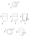
- (f) is a longitudinal sectional view. It is the partial assembly figure which inserted the application part (fiber body) of Example 2 in the application cover, (a) is a front lower perspective view, (b) is a front view, (c) is a front upper perspective view, (d). Is a top view, (e) is a side view, and (f) is a longitudinal sectional view.
- FIG. 4 is a component diagram of a cover alone of Example 3, wherein (a) is a front upper perspective view, (b) is a front view, (c) is a front lower perspective view, (d) is an upper view, and (e) is a side view. (F) is a longitudinal sectional view, and (g) is a rear view. It is the partial assembly figure which inserted the application body (fiber body) of Example 3 in the cover, (a) is a front upper perspective view, (b) is a front view, (c) is a front lower perspective view, (d) is a front perspective view.
- FIG. 6 is a component diagram of an application cover of Example 4, wherein (a) is a front upper perspective view, (b) is a front view, (c) is a front lower perspective view, (d) is an upper view, and (e) is a side view. (F) is a longitudinal sectional view, and (g) is a rear view. It is the partial assembly figure which inserted the application body (fiber body) of Example 4 in the application cover, (a) is a front upper perspective view, (b) is a front view, (c) is a front lower perspective view, (d).
- FIG. 4D is a longitudinal sectional view.
- FIG. 15 is a partial assembly view in which the application body (fiber body) of FIG. 4 is inserted into the application cover of FIG. 14 in Modification 2; (a) is a front view, (b) is a front upper perspective view, and (c) is a side view.
- FIG. 4D is a longitudinal sectional view.
- coating cover of Example 6 (a) is a front view, (b) is a front upper perspective view, (c) is an upper view, (d) is a longitudinal cross-sectional view of the state of (c), (E) is a side view, (f) is a longitudinal sectional view in the state of (e), (g) is a downward view, (h) is a rear view, and (i) is a front lower perspective view.
- FIG. 1 is a half sectional view showing an applicator according to an embodiment of the invention.
- 2 to 18 are illustrations of embodiments of the respective parts.
- symbol represents the same thing.
- the application part 52 of the application body 50 impregnated with the application liquid is brought into contact so that the application liquid can be applied to an object.
- the applicator includes an applicator 50 having a flat applicator surface 58 (see FIG. 2) formed on the applicator 52, and is attached to the applicator 50 to cover the applicator 52.
- a tank-shaped inner shaft 12 is disposed so as to be movable back and forth in a substantially cylindrical outer shaft 10 with an open rear end portion 10b.
- the inner shaft 12 moves forward with respect to the outer shaft 10 to actuate a valve mechanism 14 built in the front end portion 12a of the inner shaft 12, which will be described later, and a coating liquid is provided on the front end portion 10a of the outer shaft 10.
- the applied body 50 is supplied.
- the application body 50 is covered with a coating cover 56, which will be described later, at a portion protruding forward from the front shaft 22.
- the front end portion 10a of the outer shaft 10 has a stepped small diameter, and the front surface of the front end portion 10a has a bowl-like shape of an ink introduction pipe (a pipe line through which the coating liquid flows from the valve mechanism 14 to the application body 50).
- the outer periphery (expanded in a flange shape) of the front end portion 18a is brought into contact.
- the rear portion of the application body 50 is inserted into the front end portion 18 a of the ink introduction tube 18 through the seal ring 20.
- the front shaft 22 is moved to the front end of the outer shaft.
- the front end portions of the application body 50, the seal ring 20, and the ink introduction pipe 18 are fixed to the outer shaft 10 by being externally fitted to the portion 10 a.
- a cap 24 that covers and protects the application body 50 is detachably fitted to the outer shaft front end portion 10a.
- the cap 24 is configured such that the inner cap 24a on the inner side is attached to the front shaft 22 by a spring 24b. It is energized to press.
- the inner shaft 12 has a liquid storage space 12c in which the rear end portion 12b is closed and the inside stores a coating liquid (there may contain a stirring ball 12d), while a front end portion (a front end of the inner shaft).
- Part 12a is fixed by an inner shaft 26 in a state where the valve mechanism 14 is housed therein.
- the valve mechanism 14 is housed in the front end portion 12a in which the front side of the inner shaft 12 is narrowed
- the rear end portion 18b of the ink introduction pipe 18 is slidably connected to the valve mechanism 14, and the front end portion of the valve mechanism 14 is connected.
- the inner front shaft 26 is fixed to the inner shaft front end portion 12a by screwing or the like with a packing 28 interposed therebetween.
- valve mechanism 14 is configured so that the valve seat body 30 and the valve stem body 38 move relative to each other in the axial direction along the communication path between the liquid storage space 12 c that stores the coating liquid and the coating body 50.
- the supply toward the application body 50 is allowed / stopped.
- the valve seat body 30 of the valve mechanism 14 is a substantially cylindrical body having openings at both ends in the axial direction, and a valve rod on the front side (front side valve member 32) and rear side (rear side valve member 34) inside.
- a liquid-tight portion that is in sliding contact with the body 38 is formed, the rear side opening faces the liquid storage space 12c, and the front side opening faces the application body 50 side.
- a rib for guiding the valve rod body 38 is formed on the inner wall portion of the rear valve member 34 of the valve seat body 30 so as to protrude from the inner wall portion in the radial center direction from the substantially longitudinal center to the rear side.
- the valve rod body 38 is accommodated in the hollow of the front side valve member 32 and the rear side valve member 34 of the valve seat body 30 so as to be movable back and forth.
- a spring member 36 is externally mounted on the valve rod body 38 to urge the valve rod body 38 forward.
- the front valve member 32 has a substantially cylindrical shape as a whole, with the flange having a diameter enlarged at the front end and the rear inner peripheral surface having a diameter larger than the front inner peripheral surface. The surface becomes the liquid-tight part on the front side.
- the rear valve member 34 has a substantially cylindrical shape in which a flange is enlarged at the front end and a rear end thereof is reduced in a stepped shape, and the hollow opening is provided. Become a part.
- the front valve member 32 is concentrically inserted into the rear valve member 34 from the front side and overlapped with each other in a state where the front side valve member 32 is overlapped with each other. Cover and fix to the front end 12a of the inner shaft by screwing.
- the front surface of the reduced diameter portion at the rear side end of the rear valve member 34 is a portion that receives the spring member 36.
- the front side piston member 38a that is slidably contacted with the front side valve member 32 in the valve seat body 30 in a liquid-tight state is a rear side in the valve seat body 30.
- a rear-side piston portion 38b that is slidably contacted with the rear-side liquid-tight portion of the valve member 34 in a liquid-tight state is provided, and between the outer periphery of the substantially central portion of the valve rod body 38 and the inner surface of the valve seat body 30.
- a space 40 through which the coating liquid is circulated is provided.
- the piston portion 38a on the front side of the valve rod body 38 is formed by a flexible umbrella-shaped flange having an enlarged diameter.
- the rear piston portion 38b is formed on the smooth outer peripheral surface so as to be rearwardly narrowed, and when the valve rod body 38 moves rearward, the opening of the rear valve member 34 has a narrow rear end portion. After passing, the thicker central portion is in close contact with the rear liquid-tight portion of the rear valve member 34 and is in sliding contact therewith.
- An annular protrusion 42 is formed on the inner wall of the outer shaft 10.
- a rear end portion 18b of the ink introduction pipe 18 communicating with the application body 50 is inserted into the front side opening of the valve seat body 30, and a coating liquid is provided in the ink introduction pipe 18. Is inserted into the applying body 50.
- the applicator 50 can be a fiber body such as acrylic, nylon, polyester, polyacetal (POM), or the like.
- polypropylene (PP), polybutylene naphthalate (PBT), nylon (PA), polyacrylonitrile (PAN), front shaft 22, cap 24, inner cap 24a, and inner front shaft 26 are arranged on the inner shaft and outer shaft 10.
- Polybutyl terephthalate (PBT), polypropylene (PP), nylon (PA), polyacrylonitrile (PAN), packing 28 has EPDM, silicone, NBR (nitrile rubber), IIR (polyisobutylene rubber), fluorine, low density in seal ring Polyethylene (LDPE, LLDPE), high density polyethylene (HDPE), polypropylene (PP), front valve member 32 of valve seat 30, rear valve member 34, valve stem body 38 with high density polyethylene (HDPE), low density Polyethylene (LDPE, LLDPE), Polypropylene Ren (PP), can be used stainless steel (SUS) to the spring 24b and the spring member 36 of the cap 24.
- SUS stainless steel
- the guide rod 44 is made of a material having good wettability to the coating solution, for example, a metal such as stainless steel (SUS), a resin such as polyacetal (POM), a fiber bundle core such as polyester or acrylic, or sintered. It is preferable to use a synthetic resin molded core having a liquid passage in the axial direction, such as a body, polyacetal (POM).
- the applicator is preferably for a French nail for applying a coating solution to the tip of the nail, and the viscosity of the French nail coating solution is a viscosity that can be absorbed / applied to the coated body 50 made of a fibrous body. It is desirable that the viscosity is within a range of 50 mpa ⁇ s to 200 mpa ⁇ s.
- the material of the coating cover 56 is a polymer plastic or metal material made of polypropylene (PP), polyethylene (PE), polybutyl terephthalate (PBT), polyacetal (POM), nylon (PA), etc., and French nail It is preferable that the material be chemically resistant to the organic solvent-based liquid used in the above.
- FIG. 2 shows an application body 50 according to the first embodiment.
- the applicator used in Example 1 has the same outer diameter as the applicator 50 of the applicator shown in FIG.
- the application body 50 has a substantially bar shape, and is formed by processing a rectangular notch in the application portion 52 at the front end so as to exhibit a U-shape at the side.
- the application surface 58 which opposes in a U-shape is formed.
- the U-shaped depth was 1.5 mm and the U-shaped width was 1.5 mm. Therefore, the nail entry limit is 1.5 mm, and application is possible up to a nail thickness of 1.5 mm.
- This fibrous body was incorporated in the applicator shown in FIG. 1 and the applicability was evaluated.
- the nail was fixed at the limit of the fiber body by inserting the nail to the limit of the fiber body.
- the fiber body was applied while following the shape of the front end of the nail, whereby a line with a width of 1.5 mm could be drawn easily and beautifully.
- Example 2 relates to an application cover.
- FIG. 3 is a component diagram of the coating cover.
- FIG. 4 is a component diagram of the application body 50.
- FIG. 5 is an assembly view of the coating cover 56 and the coating body 50.
- the coating cover 56 has a cap shape in which the front end portion has a spherical shape and the rear portion slightly expands in a bowl shape.
- the coating cover 56 is formed with a window-shaped slit 54 cut out in a rectangular shape at the front end thereof.
- a stepped portion 54a is formed continuously in a stepped shape continuously with one end surface of the slit 54, and an inner surface and an outer surface are formed in the same spherical shape on the other end surface of the slit 54.
- the slit 54 has a width of 1.5 mm, a nail entry limit of 1.8 mm, and an outer diameter of the application cover 56 of 5.3 mm.
- the inner shape is a key shape similar to that of the application body, and is communicated.
- the application body 50 has a flat application surface 58 along the axial direction of the application body 50 by notching one side of the front end portion of the application part 52 into a notch shape. Is formed.
- the coated body 50 having an outer diameter of 4.5 mm was used, the front end serving as the coated portion 52 was spherically processed, and surface grinding was performed along the axial direction to form the coated surface 58.
- the recess 60 is formed by cutting out the central portion with a diameter of ⁇ 4 mm and the peripheral surface with a small diameter.
- the fibrous body used as the coated body 50 was one having a porosity of 50% or more.
- Example 2 when the application body 50 is mounted in the application cover 56, the application surface 58 is exposed to the slit 54 by 0.5 mm as shown in FIG. If the thickness of the nail is about 1 mm, it can be inserted without difficulty.
- the position of the application body 50 is determined by the spherical portion or step portion 54 a of the application cover 56.
- a nail is inserted into the slit 54, the nail is fixed at the limit of entry, and the applicator is moved to the left and right along the front end shape of the nail to easily draw a stable width. I was able to draw beautifully.
- the coating cover 56 shown in FIG. 6 has a configuration in which the width of the slit 54 (depth when viewed from the side) is increased, but the coating cover 56 shown in FIG. 3 is replaced with the coating cover 56 shown in FIG. FIG. 7 shows the assembly configuration, and the coating width of the slit 54 can be changed.
- FIG. 8 is an explanatory diagram of the coating cover 56 of the third embodiment.
- FIG. 9 is an assembled view of the application cover 56 and the application body 50 according to the third embodiment.
- the application body 50 of this Example 3 is the same as that of Example 2 shown in FIG.
- the assembly of the second embodiment is further improved.
- a hole 56a is provided on the upper surface of the coating cover 56 in addition to the slit 54 so that the outer peripheral surface of the coating portion 52 is exposed from the hole 56a. It has become.
- a drawn line with a stable width can be easily and neatly drawn, and further, the application work can be corrected or pointed at the coating portion 52 exposed from the hole provided on the upper surface. Making was easy.
- FIG. 10 is a component diagram of the coating cover 56 according to the fourth embodiment, and FIG. 11 is an explanatory diagram of the assembly.
- Example 4 the application body 50 shown in FIG. 2 was used, and the application cover 56 and the application body 50 were assembled as shown in FIG.
- Example 4 as shown in FIG. 10, slits 54 a and 54 b having different depths (and widths) were processed one by one in the application cover 56, and the application body 50 was inserted into the application cover 56.
- the application surfaces 58 and 58 facing each other face (expose) the slits 54a and 54b.
- Example 2 In the coating operation, the same result as in Example 2 was obtained. Further, since the slits 54a and 54b are different, two drawn lines having different line widths can be drawn.
- FIG. 12 is a component diagram of the application body of Example 5, and FIG. In Example 5, the application body of FIG. 12 was assembled using the application cover 56 of Example 4 shown in FIG. 10 in the assembly diagram of FIG.
- the application body 50 is different from the embodiment 4 in that the application part 52 at the front end of the application body 50 is cut out from both side surfaces across the shaft, processed into a convex shape, and applied.
- the surfaces 58 and 58 are points formed on both side surfaces of the convex application portion 52.
- the application surfaces 58 and 58 are exposed from the slits 54a and 54b, respectively.
- two drawn lines having different line widths could be drawn here.
- FIG. 14 shows an application cover 56 according to a second modification of the second embodiment
- FIG. 15 shows an application cover 50 inserted into the application cover 56.
- a bowl-shaped portion formed continuously or integrally with the rear portion of the application cover 56 is extended to integrate the application cover 56 with the front shaft 22.
- the application body 50 shown in FIG. 4 is one in which one side of the application part 52 is cut out in a notch shape to form an application surface 58.
- a portion corresponding to the front axis of the application cover 56 is denoted by reference numeral 22 ⁇ / b> A.
- This modification 2 has an advantage that the number of parts of the front shaft 22 can be reduced when used in the applicator of the embodiment shown in FIG. 1 as compared with the above-described examples 1 to 5.
- FIG. 16 is a partial assembly view in which the application body (fiber body) according to the sixth embodiment is inserted into the application cover 56 and attached to the front shaft 22.
- FIG. 17 is a partial assembly view in which the application body (fiber body) is inserted into the application cover before being attached to the front shaft 22.
- FIG. 18 is a component diagram of the application cover.
- the third embodiment shown in FIGS. 8 and 9 is further improved.
- the rear portion of the coating cover 56 extends in a cylindrical shape as compared with the shape of the third embodiment (in the cylindrical portion 56b). Structure).
- the application cover 56 is assembled by mounting the application body 50 and the cylindrical portion 56 b at the rear of the application cover 56 in the front shaft 22.
- a portion of the application cover 56 that is opened in an umbrella shape hits the front shaft 22 against the front end edge, and the cylindrical portion 56 b enters the front shaft 22.
- the application body 50 is sandwiched and fixed to the front shaft 22 via the cylindrical portion 56 b of the application cover 56.
- the application portion 52 on the conical side surface of the application body 50 is exposed from the hole 56 a on the upper surface, and the flat application surface 58 faces the slit 54.
- the application cover 56 made of an elastic resin material (the rear cylindrical portion 56 b formed in a cylindrical shape) is interposed between the application body 50 and the front shaft 22. Therefore, the sense of unity between the front shaft 22 and the application cover 56 and the prevention of the application cover 56 from falling off from the front shaft 22 can be effectively performed.
- the applicator 50 and the applicator cover 56 of the first to sixth embodiments or the first and second modifications are applied to the valve mechanism 14 for supplying the content liquid by knocking the rear end portion 12b of the inner shaft 12.
- the applicator is configured to send the content liquid in the liquid storage space 12c of the inner shaft 12 to the application body 50 and apply the liquid to the toe with the application body 50 capable of absorbing / applying the liquid. It is processed into a U-shape, and by inserting the nail into the slit 54 until the U-shaped entry limit, the positioning of the nail is completed and fixed, so that the application part 52 follows the front end shape of the nail.
- the liquid discharged from the container and supplied to the application body 50 can be made into a nail art application part that can be easily applied to the nails.
- the shape of the application body 50 may be formed in a curved surface, and the application cover 56 may be omitted if it can be applied only by the application body 50. Omission of the application cover 56 allows easy application with a simple configuration.
- the applicator of the present invention is preferably a French nail applied to the periphery of the toe, which is associated with the makeup of the fingertips of the hand, but can also be used in the same manner when applying to the tip of a small object such as the toe with the same width. .
Landscapes
- Coating Apparatus (AREA)
- Pens And Brushes (AREA)
Abstract
Provided is an applicator implement with which it is possible to draw a line easily, rapidly, and stably, without regard to the experience or skill of a person, and with which application can be prepared in a short time and carried out accurately such that a line can be taken in parallel with the leading end of a nail without regard to the curved face of the nail, i.e., with which it is possible to achieve satisfaction in the finish of a French nail operation on an individual basis. This applicator implement comprises an applicator body (50) wherein a flat applicator face is formed on an applicator unit, and an applicator cover (56) which is mounted on the applicator body and covers the applicator unit (52), and wherein a slit (54) is formed which communicates from the outer part to the inner part. In a state wherein the applicator cover (56) covers the applicator unit (52), the applicator face of the applicator unit (52) is located within the slit (54), and application in a constant width of a manicure applicator fluid upon a nail with an applicator face (58) is possible by inserting the nail through the slit (54).
Description
本発明は、特に手の指先の化粧に付随する、爪先周辺にマニキュア液を塗布するネイルアート分野において、フレンチネイル(爪前端に塗布液を塗布する)に関するもので、主に手の爪先周辺(端から前端から端まで)への液の塗布を短時間で容易且つ正確に行えることを目的とし、爪前端形状に倣い一定幅で塗布でき、利き手や経験に頼らず描線を描ける塗布具に関する。
The present invention particularly relates to a French nail (applying a coating solution to the front end of a nail) in the nail art field where nail art is applied around the toe, which is associated with makeup of the fingertips of the hand. The present invention relates to an applicator that can be applied with a constant width following the shape of the front end of the nail and can draw a line without depending on the dominant hand or experience, for the purpose of easily and accurately applying the liquid from the end to the front end.
容器内の塗布液を塗布体で取り出して目的箇所に塗布する塗布具には、例えばマニキュア液を塗布するマニキュア製品がある。
An example of an applicator that takes out the application liquid in the container with an application body and applies it to a target location is a nail polish product that applies a nail polish liquid.
マニキュアには、手の指先の化粧に付随する、爪先周辺にマニキュア液を塗布するフレンチネイルが知られている。
For French manicure, a nail polish is applied around the toes that comes with the makeup of the fingertips.
このフレンチネイルは、個人で爪に塗布する場合の一般的な一例であり、フレンチネイルを塗布する直前にベース液を爪全面に塗布し、フレンチネイル塗布後、更に保護用のコート液を塗布する。このような多くの工程を必要とするため、出来るだけ簡便且つ素早く、綺麗に仕上がる塗布方法が求められている。
This French nail is a general example when applied to the nail by an individual. The base solution is applied to the entire surface of the nail immediately before applying the French nail, and after the French nail is applied, a protective coating solution is further applied. . Since many processes are required, there is a demand for a coating method that finishes as cleanly and simply as possible.
従来、一般的に知られているフレンチネイルの塗布方法は、以下の4つに分類することができる。
Conventionally, generally known methods for applying French nail can be classified into the following four types.
1.ハケやペン芯で塗布する。
最も一般的なフレンチネイルの塗布方法であり、ベース液と同様の塗布部(ハケやペン芯)にて爪前端に塗布動作を行う。その際、フレンチネイル部形状の専用シートや、指を固定し塗布しやすくする固定具を使うこともある(例えば特開2004-59035号公報:特許文献1参照)。 1. Apply with a brush or pen nib.
This is the most common method for applying French nail, and the application operation is performed on the front end of the nail with the same application part (brush or pen core) as the base liquid. At that time, a special sheet having a French nail portion shape or a fixing tool that fixes a finger to facilitate application may be used (for example, see Japanese Patent Application Laid-Open No. 2004-59035: Patent Document 1).
2.形状加工した専用ハケで塗布する。
この専用ハケは、爪のラウンド形状に擬似したハケ形状でかつ、正面方向は爪正面曲面に擬似したU字形状となっている。専用ハケの形状で、そのまま爪に塗布することによってフレンチネイル動作を行うことができる(例えば特開2004-8826号公報:特許文献2参照)。 2. Apply with a specially shaped brush.
This exclusive brush has a brush shape that simulates the round shape of the nail, and the front direction has a U-shape that simulates the front surface of the nail. A French nail operation can be performed by applying it to the nail as it is in the shape of a dedicated brush (see, for example, Japanese Patent Application Laid-Open No. 2004-8826: Patent Document 2).
3.形状加工したペン芯を爪にあてがい塗布する。
爪前端部に略鍵状の塗布部を(繊維ペン芯)押し当て固定し、押し当てた箇所をガイド代わりに塗布部をそのまま左右に動かすことで、利き手に関係なくフレンチネイル動作を行える(例えば特開2006-204332号公報:特許文献3参照)。 3. Apply the shaped pen core to the nail.
By pressing and fixing the approximately key-shaped application part (fiber pen core) to the front end of the nail and moving the application part directly to the left and right instead of the guide, the French nail operation can be performed regardless of the dominant hand (for example, JP, 2006-204332, A: Refer to patent documents 3).
4.形状加工したシールを貼る。
液を使用せずに、薄いシールをピンセット等でつかみ、爪先に貼り付けることでフレンチネイル動作を行える(例えば特開2006-296620号公報:特許文献4参照)。 4). Affix a shaped seal.
Without using the liquid, a French nail operation can be performed by grasping a thin seal with tweezers or the like and sticking it to the toe (see, for example, JP-A-2006-296620: Patent Document 4).
しかしながら、前記特許文献1開示の塗布具は、通常のフリーハンドでハケやペン芯で爪前端を塗布するものであるが、フリーハンドであるがゆえに本人の経験・技術が非常に係わり、初心者のうちは位置決めが安定せず、塗布が難しいものであった。また経験・技術が向上しても仕上がり自体に満足感が得られないことが多かった。
However, the applicator disclosed in Patent Document 1 applies the front end of the nail with a brush or pen core in a normal freehand, but because it is a freehand, its experience and technology are very involved, Among them, positioning was not stable and application was difficult. In addition, even if experience and technology improved, the finish itself was often not satisfactory.
また、特許文献2開示の塗布具も、上記と同様、塗布先への位置が決めづらく、習得に時間を要するものであった。また利き手への塗布についても同様と言える。ハケ形状もラウンド形状に固定されているため、フラット状の爪先には不向きであった。更に平面視でU字形状のため塗布液が下に垂れ、爪中央の塗布液が薄くなりがちである。
Also, the applicator disclosed in Patent Document 2 is difficult to determine the position to the application destination as described above, and it takes time to learn. The same applies to the application to the dominant hand. Since the brush shape is also fixed in a round shape, it is not suitable for flat toes. Furthermore, since the U-shaped in a plan view, the coating solution hangs down and the coating solution at the center of the nail tends to become thin.
また、特許文献3開示の塗布具は、利き手に影響なく左右の手の爪に安定した塗布が可能であるが、爪先へ押し当てることで位置が固定されるが、押し当てが強いと位置がずれることが多かった。特に爪の端では塗布部が固定箇所から一部外れ、爪を汚す傾向にあった。また、使用するたびにペン芯を爪先に押し当てているため、ペン芯形状の維持(耐久性)に課題があった。
In addition, the applicator disclosed in Patent Document 3 can stably apply to the nails of the left and right hands without affecting the dominant hand, but the position is fixed by pressing against the toes, but if the pressing is strong, the position is fixed. There were many deviations. In particular, at the end of the nail, the application part tends to be partially detached from the fixed part and dirty the nail. Further, since the pen core is pressed against the toe every time it is used, there is a problem in maintaining the pen core shape (durability).
また、特許文献4開示の塗布具は、ピンセット等でシールを台紙から剥がし、セッティングするため、爪先への縦横方向がずれやすく見栄えを損なう傾向にあった。そのため習得に時間が必要であった。またシール面を汚してしまうと、密着力が弱くなり剥がれやすい課題があった。また爪とシールの間に必然的にシールの厚み分段が発生し、違和感を伴っていた。更に爪に比べ非常に剛性がもろいため傷つきやすく耐久性に劣る。シールであるがためコスト高でもあった。
In addition, the applicator disclosed in Patent Document 4 has a tendency to deviate in appearance because the seal is peeled off from the mount with tweezers or the like and set in the vertical and horizontal directions. Therefore, it took time to learn. Further, if the sealing surface is soiled, there is a problem that the adhesion is weakened and easily peeled off. In addition, a thickness step of the seal inevitably occurs between the nail and the seal, which is uncomfortable. Furthermore, it is very fragile compared to the nails, so it is easily damaged and inferior in durability. Although it was a seal, it was expensive.
本発明は、上記記載の課題を解決するためのものであり、その人の経験やスキルに関係なく、容易且つ迅速に、安定した描線ができ、且つ、爪前端に平行したラインが取れるようにして、爪曲面に関係なく、短時間で用意且つ正確に塗布することができる、すなわち個人でのフレンチネイル動作の仕上がりに満足し得る塗布具を提供することである。また、コストが少なく、爪を汚すことも回避できる塗布具を提供することである。
The present invention is intended to solve the above-described problems, and can easily and quickly draw a stable line and take a line parallel to the front end of the nail regardless of the person's experience and skill. Thus, an object of the present invention is to provide an applicator that can be prepared and applied in a short time regardless of the curved surface of the nail, that is, satisfying the finish of an individual French nail operation. It is another object of the present invention to provide an applicator that is low in cost and can avoid soiling the nails.
本発明は、塗布液が含浸される塗布体の塗布部を接しさせて対象物に当該塗布液を塗布可能にする塗布具において、
塗布部に平坦な塗布面が形成された塗布体と、
前記塗布体に装着して前記塗布部を覆うものであって、外部から内部に連通するスリットが形成された塗布カバーとを備え、
前記塗布カバーが前記塗布部を覆った状態で、前記スリット内に前記塗布部の塗布面が位置し、前記スリットを通して対象物を挿入することにより塗布面によって該対象物の所定部に塗布液の塗布が可能になっていることを特徴とする塗布具である。 The present invention provides an applicator that allows the application liquid to be applied to an object by contacting the application portion of the application body impregnated with the application liquid.
An application body having a flat application surface formed on the application part;
It is attached to the application body and covers the application part, and includes an application cover in which a slit communicating from the outside to the inside is formed,
With the application cover covering the application part, the application surface of the application part is positioned in the slit, and the object is inserted into the predetermined part of the object by the application surface by inserting the object through the slit. An applicator characterized in that application is possible.
本発明では、簡単に安定し塗布できる。また、塗布部の塗布面を例えばコの字状の内面に形成することで、爪を挿入可能とし、爪を塗布したい方向に塗布部を動かすだけで安定した描線が得られる。
In the present invention, it can be applied easily and stably. Further, by forming the application surface of the application part on, for example, a U-shaped inner surface, a nail can be inserted, and a stable line can be obtained simply by moving the application part in the direction in which the nail is desired to be applied.
本発明において、対象物に塗布するための塗布体は、繊維及び樹脂により加工された繊維体からなることが好適である。
In the present invention, it is preferable that the application body to be applied to the object is a fiber body processed with fibers and resin.
また、本発明において、前記塗布体は、前端部に前記塗布体の軸方向に沿った平面の塗布面が形成されていて、爪先をスリットに通し前記塗布面によって塗布液を前記爪先に所定幅で塗ることが可能に構成された、フレンチネイル用の塗布具であることが好適である。
したがって、塗布体となる繊維体に爪の進入限となるコの字形状を加工し、その進入限まで爪先を入れることで、爪の位置決めが可能となる。これにより塗布部と爪は固定され、且つ被塗布面となる爪先が、塗布体の塗布部に当たり、液が塗布され、塗布部又は爪を塗布したい方向に動かすだけで安定した描線が得られる。 Further, in the present invention, the application body has a flat application surface formed along the axial direction of the application body at a front end, and the application liquid is applied to the toe by the application surface through the slit. It is preferable that the applicator is a French nail applicator configured so that it can be applied.
Therefore, the nail shape can be positioned by processing a U-shape that is the limit of nail entry into the fiber body that is the application body and inserting the nail tip to the limit of entry. As a result, the application part and the nail are fixed, and the tip of the nail serving as the application surface hits the application part of the application body, the liquid is applied, and a stable line can be obtained simply by moving the application part or the nail in the desired direction.
また、塗布体の前端のコの字形状の凹み深さを変えることで、爪先への塗布幅を変えられることができる。
Also, the width of application to the toe can be changed by changing the depth of the U-shaped dent at the front end of the application body.
また、塗布体前端のコの字の幅を変えることで、爪先の厚みに関係なく適度な幅になっていることができる。
Also, by changing the U-shaped width at the front end of the coated body, the width can be made appropriate regardless of the thickness of the toe.
また、塗布体前端のコの字の上面下面は、塗布面正面から見て、直線(面自体は平面)又はR10以上の曲線(断面は平面)になっており、各指に曲面差があっても、スムーズに塗布できる。
In addition, the upper and lower surfaces of the U-shape at the front end of the application body are straight lines (the surface itself is a flat surface) or a curve of R10 or more (the cross section is a flat surface) when viewed from the front of the application surface, and there is a difference in curved surface between each finger. However, it can be applied smoothly.
本発明において、前記塗布体は、前端部に前記塗布体の軸方向に沿った平面の塗布面が形成されていて、爪先を塗布カバーのスリットに通し前記塗布面によって塗布液を前記爪先に所定幅で塗ることが可能に構成された、フレンチネイル用の塗布具であることが好適である。
In the present invention, the application body has a flat application surface formed along the axial direction of the application body at a front end portion, and a coating liquid is applied to the toe tip by passing the toe through the slit of the application cover. The applicator for French nail is preferably configured to be able to be applied with a width.
このように、塗布カバーには、塗布体を覆うような、後方より塗布体を挿入できる孔が加工されていて、且つ、前端にはスリットが設けられており、塗布体を挿入することで、塗布体の一部がスリット部より露出するような、カバーを付与することで、塗布体の塗布面が、塗布カバーのスリット上面より露出し、その面にて被塗布面への塗布が可能となる。また露出面と塗布カバーの下面には爪を入れられる十分な隙間が空く形状になっているものにできる。
In this way, the application cover is processed with a hole into which the application body can be inserted from the back so as to cover the application body, and the front end is provided with a slit, and by inserting the application body, By applying a cover so that a part of the coated body is exposed from the slit, the coated surface of the coated body is exposed from the top surface of the slit of the coated cover and can be applied to the coated surface on that surface. Become. Further, the exposed surface and the lower surface of the coating cover can be formed so as to have a sufficient gap for inserting a nail.
また、塗布カバーのスリット形状は正面方向から見て、平面もしくはR10以上の曲線であり、各指に曲面差があっても、スムーズに塗布できることができる。
Also, the slit shape of the coating cover is a flat surface or a curve of R10 or more when viewed from the front direction, and even if there is a difference in curved surface between fingers, it can be applied smoothly.
また、塗布カバーのスリット奥行き(深さ)を変更することで、爪の進入限が変わるため、被塗布部となる爪への塗布幅が変更できる。
Also, by changing the slit depth (depth) of the application cover, the entry limit of the nail changes, so that the application width to the nail as the application part can be changed.
本発明において、塗布体の軸方向中央付近に前後の外径に比べて縮径して形成し、塗布カバーを塗布体に被せて組み立てた状態では前記縮径した箇所が軸筒内に収納されていることが好適である。
In the present invention, in the vicinity of the center in the axial direction of the application body, the diameter is reduced as compared with the front and rear outer diameters, and in the state where the application cover is put on the application body and assembled, the reduced diameter portion is stored in the shaft cylinder. It is suitable.
この構造によって、塗布液を塗布体に送ったときに、繊維体等の塗布体の液吸収を超えて液飽和した場合でも、一時的にその縮径した部分に液が保持でき、液あふれを防止できる。
With this structure, when the coating liquid is sent to the coating body, even if the liquid saturation exceeds the liquid absorption of the coating body such as the fiber body, the liquid can be temporarily retained in the reduced diameter portion, and the liquid overflows. Can be prevented.
また、本発明において、塗布カバーには、スリットの他に塗布体の外側面を露出させるための孔が設けられており、塗布カバーを塗布体に装着した状態で露出した塗布体の外側面も対象物に塗布可能にしたことが好適である。
この塗布体の外側面露出させる孔から塗布体で対象物に塗布できるので利便性が高い。 In the present invention, the application cover is provided with a hole for exposing the outer surface of the application body in addition to the slit, and the outer surface of the application body exposed in a state where the application cover is mounted on the application body is also provided. It is preferable that application to an object is possible.
Since it can apply | coat to a target object with an application body from the hole exposed on the outer surface of this application body, it is highly convenient.
本発明において、前記塗布カバー後方から塗布体を挿入できる孔が形成され、前端にそれぞれ奥行きが異なる2つのスリットが開口し、前記塗布体には、塗布部の前端の切り込んだ内側に塗布面が2面対向して形成されており、前記塗布カバー内に塗布体を挿入することによって、前記塗布カバーの各スリットから各塗布面が臨む形態となっており、各スリットを通して塗布面の間に爪を入れられる十分な隙間が空く形状で、その臨んだ塗布面にて爪先の一面にのみ塗布できるものであり、2つあるスリットのどちらかを選択することで、異なる線幅のラインを引くことができるフレンチネイル用に用いることが好適である。
In the present invention, a hole into which the application body can be inserted from the back of the application cover is formed, two slits having different depths are opened at the front end, and the application surface has an application surface on the inner side where the front end of the application part is cut. It is formed so as to face two surfaces, and by inserting an application body into the application cover, each application surface faces each slit of the application cover, and a nail is provided between the application surfaces through each slit. With a shape that leaves enough space to be inserted, it can be applied only to one surface of the toe at the application surface that faces it, and by selecting one of the two slits, draw lines with different line widths It is preferable to use it for French nails that can be used.
また、本発明において、前記塗布カバー後方から塗布体を挿入できる孔が形成され、前端にそれぞれ奥行きが異なる2つのスリットが開口し、前記塗布体には塗布部の前端の外側に塗布面が2面離隔して形成されており、前記塗布カバー内に塗布体挿入することによって、塗布カバーの各スリットから各塗布面が臨む形態となっており、コの字と露出した繊維体の間には爪を入れられる十分な隙間が空く形状で、その臨んだ塗布面にて爪先の一面にのみ塗布できるものであり、2つあるスリットのどちらかを選択することで、異なる線幅のラインを引くことができるフレンチネイル用に用いることが好適である。
In the present invention, a hole into which the application body can be inserted from the rear of the application cover is formed, two slits having different depths are opened at the front end, and the application surface has two application surfaces outside the front end of the application portion. It is formed with a surface separation, and by inserting the application body into the application cover, each application surface faces from each slit of the application cover, between the U shape and the exposed fiber body With a shape that leaves enough space to put the nail, it can be applied only to one surface of the nail at the application surface facing it, and by selecting one of the two slits, draw lines with different line widths It is suitable to use for French nails that can be used.
上記のように塗布カバー前端のスリットを2つ設けて、それぞれのスリットの奥行きの異なるように加工することで、前記塗布カバーのスリット面の幅方向の片側から塗布体が露出する形態になり、塗布体となる繊維体とスリット下面の間には爪を入れられる十分な隙間が空く形状で、その露出した面で爪先の一面にのみ塗布できるものであり、2つ設けたスリットの奥行き(進入限)が違うため、異なる線幅のラインを引くことができる。
By providing two slits at the front end of the application cover as described above and processing the slits to have different depths, the application body is exposed from one side in the width direction of the slit surface of the application cover, There is a sufficient gap between the fiber body to be applied and the lower surface of the slit to allow the nail to be inserted, and the exposed surface can be applied only to one surface of the toe. Because the limit is different, lines with different line widths can be drawn.
本発明において、前記塗布具が、前部の先軸と前記先軸の前方の前記塗布カバーとで前記塗布体を覆うものであり、前記塗布カバーは前記先軸から取り外し可能であり、且つ、前記塗布体も取り外し可能であることが好適である。
In the present invention, the applicator covers the application body with a front shaft at the front and the application cover in front of the front shaft, and the application cover is removable from the front shaft, and It is preferable that the application body is also removable.
本発明において、前記塗布具が、前部の先軸と前記先軸の前方の前記塗布カバーとで前記塗布体を覆うものであり、前記塗布カバーと前記先軸が一体で構成されていてもよい。このようにすることで部品点数が減り、コストが少なくできる。
In the present invention, the applicator covers the applicator with a front shaft at the front and the application cover in front of the front shaft, and the application cover and the front shaft may be configured integrally. Good. By doing so, the number of parts can be reduced and the cost can be reduced.
本発明において、塗布カバーの材質は、PP(ポリプロピレン)、PE(ポリエチレン)、PBT(ポリブチレンテレフタレート)、POM(ポリオキシメチレン)、PA(ポリアミド)等の高分子プラスチック又は金属からなる材料であることが好適である。フレンチネイルに使用する有機溶剤系の液体に対し、耐薬品性のある材料であることが更に好適である。
In the present invention, the material of the coating cover is a material made of polymer plastic or metal such as PP (polypropylene), PE (polyethylene), PBT (polybutylene terephthalate), POM (polyoxymethylene), PA (polyamide). Is preferred. It is more preferable that the material is resistant to chemicals with respect to the organic solvent-based liquid used for French nails.
本発明は、塗布液が含浸される塗布体の塗布部を接しさせて対象物に当該塗布液を塗布可能にする塗布具において、
塗布部表面にスリットが形成された塗布体を備え、
前記塗布体は、前端部に前記塗布体の軸方向に沿った塗布面が形成されていて、爪先をスリットに通し前記塗布面によって塗布液を前記爪先に所定幅で塗ることが可能に構成されたことを特徴とする塗布具である。 The present invention provides an applicator that allows the application liquid to be applied to an object by contacting the application portion of the application body impregnated with the application liquid.
Provided with an application body with slits formed on the surface of the application part,
The application body has an application surface formed along the axial direction of the application body at a front end portion, and is configured so that a toe can be passed through the slit and the application liquid can be applied to the toe with a predetermined width by the application surface. This is an applicator characterized by that.
本発明の塗布具によれば、塗布部は、例えば容器内の塗布液を繰り出しやノック等の動作にて塗布部に送り、対象物に塗布するものであり、塗布部の前端に、コの字上の加工を施し、塗布カバーが塗布部を覆った状態で、前記スリット内に前記塗布部の塗布面が位置し、前記スリットを通して爪等の対象物を挿入して、塗布体を爪形状に倣うように左右に動かすことにより塗布面によって該対象物の所定部例えば爪の前端部に一定幅に塗布液の塗布が容易に可能になる。
According to the applicator of the present invention, the applicator, for example, feeds the coating liquid in the container to the applicator by feeding or knocking, and applies it to the object. The application surface of the application part is positioned in the slit with the application cover covering the application part, and an object such as a nail is inserted through the slit so that the application body has a nail shape By moving left and right so as to follow the above, it is possible to easily apply the coating liquid to a predetermined portion of the object, for example, the front end portion of the nail with a certain width by the coating surface.
このような簡単な動作なため、ネイルアートにおける従来の不満点である浪費時間(習得に要する時間、利き手以外での塗布技術、不安定な塗布描線、失敗による爪の汚し等)を大幅に改善できる。特に迅速且つ綺麗な仕上がりを特徴とするためネイルアートを一層楽しむことができる。
Because of this simple operation, the wasted time (time required for learning, non-handedness application technology, unstable application drawing, nail smearing due to failure, etc.), which is a conventional dissatisfaction point in nail art, has been greatly improved. it can. In particular, nail art can be enjoyed further because it features a quick and beautiful finish.
他に繊維体等の塗布体を覆う塗布カバーにスリットを設け、塗布体を挿入することで、塗布カバーのスリットより塗布体が露出し、塗布カバーのスリットの進入限まで爪を入れ、固定することで、爪の片面に塗布できるものである。
In addition, a slit is provided in the coating cover that covers the coated body such as the fiber body, and the coated body is inserted, so that the coated body is exposed from the slit of the coating cover, and the nail is inserted and fixed to the limit of the slit of the coating cover. Thus, it can be applied to one side of the nail.
また、スリットの奥行きを変更することで爪への塗布幅も変えることができる。
また、塗布カバーに奥行きの違うスリットを2つ設けることで、2つの塗布幅を選択できるものになるという優れた効果を奏し得る。 Moreover, the application | coating width | variety to a nail | claw can also be changed by changing the depth of a slit.
Further, by providing two slits with different depths in the application cover, an excellent effect can be obtained that two application widths can be selected.
本発明は、塗布部表面にスリットが形成された塗布体を備え、該塗布体の前端部に前記塗布体の軸方向に沿った塗布面を形成し、爪先をスリットに通し前記塗布面によって塗布液を前記爪先に所定幅で塗ることが可能に構成することによって、塗布カバーを省略でき、塗布体の表面のスリットを通して、爪先を塗布面に接しさせて、塗布液を爪先に所定幅に塗ることが可能になる。塗布カバーの省略により、より構成が簡単になる。
The present invention includes an application body in which a slit is formed on the surface of the application portion, an application surface along the axial direction of the application body is formed at a front end portion of the application body, and a toe is passed through the slit and applied by the application surface. By making it possible to apply the liquid to the toe with a predetermined width, the coating cover can be omitted, and the coating liquid is applied to the toe with a predetermined width by bringing the toe into contact with the application surface through a slit on the surface of the application body. It becomes possible. By omitting the coating cover, the configuration becomes simpler.
以下、本発明の実施の形態について添付図面を参照して説明する。
図1は発明の実施形態に係る塗布具を示す半断面図である。図2~図18は各部の実施例の説明である。なお、同一符号を付した部分は同一物を表す。 Embodiments of the present invention will be described below with reference to the accompanying drawings.
FIG. 1 is a half sectional view showing an applicator according to an embodiment of the invention. 2 to 18 are illustrations of embodiments of the respective parts. In addition, the part which attached | subjected the same code | symbol represents the same thing.
図1に示すよう実施形態に係る塗布具では、塗布液が含浸される塗布体50の塗布部52を接しさせて対象物に当該塗布液を塗布可能にするものである。塗布具には、塗布部52に平坦な塗布面58(図2参照)が形成された塗布体50と、前記塗布体50に装着して前記塗布部52を覆うものであって、外部から内部に連通するスリット54が形成された塗布カバー56とを備えており、前記塗布カバー56が前記塗布部52を覆った状態で、前記スリット54内に前記塗布部52の塗布面58が位置し、前記スリットを通して対象物を挿入することにより塗布面58によって該対象物の所定部に塗布液の塗布が可能になっているものである。
As shown in FIG. 1, in the applicator according to the embodiment, the application part 52 of the application body 50 impregnated with the application liquid is brought into contact so that the application liquid can be applied to an object. The applicator includes an applicator 50 having a flat applicator surface 58 (see FIG. 2) formed on the applicator 52, and is attached to the applicator 50 to cover the applicator 52. An application cover 56 formed with a slit 54 communicating therewith, with the application cover 56 covering the application part 52, the application surface 58 of the application part 52 is located in the slit 54, By inserting the object through the slit, the application surface 58 can apply the coating liquid to a predetermined portion of the object.
〔塗布具の全体構成〕
実施形態の塗布具の全体について説明する。
図1に示すように、塗布具は、後端部10bの開放された概略円筒状の外軸10内に進退動可能にタンク状の内軸12が配置されていて、ユーザーが内軸12後端部12bをノックすることによって内軸12が外軸10に対して前進して後述する内軸12の前端部12a内装のバルブ機構14を作動させ、塗布液を外軸10前端部10aに設けた塗布体50に供給するようになっている。塗布体50は先軸22先方に突出する部分が後述する塗布カバー56で覆われている。 [Overall configuration of applicator]
The whole applicator of the embodiment will be described.
As shown in FIG. 1, in the applicator, a tank-shapedinner shaft 12 is disposed so as to be movable back and forth in a substantially cylindrical outer shaft 10 with an open rear end portion 10b. By knocking the end portion 12b, the inner shaft 12 moves forward with respect to the outer shaft 10 to actuate a valve mechanism 14 built in the front end portion 12a of the inner shaft 12, which will be described later, and a coating liquid is provided on the front end portion 10a of the outer shaft 10. The applied body 50 is supplied. The application body 50 is covered with a coating cover 56, which will be described later, at a portion protruding forward from the front shaft 22.
実施形態の塗布具の全体について説明する。
図1に示すように、塗布具は、後端部10bの開放された概略円筒状の外軸10内に進退動可能にタンク状の内軸12が配置されていて、ユーザーが内軸12後端部12bをノックすることによって内軸12が外軸10に対して前進して後述する内軸12の前端部12a内装のバルブ機構14を作動させ、塗布液を外軸10前端部10aに設けた塗布体50に供給するようになっている。塗布体50は先軸22先方に突出する部分が後述する塗布カバー56で覆われている。 [Overall configuration of applicator]
The whole applicator of the embodiment will be described.
As shown in FIG. 1, in the applicator, a tank-shaped
外軸10前端部10aは、段状に細径になっており、その前端部10a前面に、インク導入管(バルブ機構14から塗布体50側に塗布液を流通させる管路)18の椀状の前端部18aの外周(フランジ状に拡がっている)を当接させている。そのインク導入管18の前端部18aには、シールリング20を介して塗布体50の後部を挿入している。中空で先細い筒状の先軸22の中空部に前記塗布体50の中央部からシールリング20及び前記インク導入管18の前端部18aを通した状態で、該先軸22を前記外軸前端部10aに外嵌することによって、塗布体50、シールリング20及びインク導入管18の前端部を外軸10に固定するようになっている。なお、外軸前端部10aには、塗布体50を覆って保護するキャップ24が着脱可能に外嵌するようになっており、キャップ24は、内側のインナーキャップ24aがスプリング24bによって先軸22を押圧するように付勢している。
The front end portion 10a of the outer shaft 10 has a stepped small diameter, and the front surface of the front end portion 10a has a bowl-like shape of an ink introduction pipe (a pipe line through which the coating liquid flows from the valve mechanism 14 to the application body 50). The outer periphery (expanded in a flange shape) of the front end portion 18a is brought into contact. The rear portion of the application body 50 is inserted into the front end portion 18 a of the ink introduction tube 18 through the seal ring 20. In a state where the seal ring 20 and the front end portion 18a of the ink introduction pipe 18 are passed through the hollow portion of the hollow tapered tip shaft 22 from the central portion of the application body 50, the front shaft 22 is moved to the front end of the outer shaft. The front end portions of the application body 50, the seal ring 20, and the ink introduction pipe 18 are fixed to the outer shaft 10 by being externally fitted to the portion 10 a. A cap 24 that covers and protects the application body 50 is detachably fitted to the outer shaft front end portion 10a. The cap 24 is configured such that the inner cap 24a on the inner side is attached to the front shaft 22 by a spring 24b. It is energized to press.
前記内軸12は、後端部12bが閉鎖されて内部が塗布液を収容する液体収容空間12cになっており(攪拌ボール12dを収容する場合がある)、一方、前端部(内軸の前端部)12aに前記バルブ機構14を内装した状態で内先軸26によって固定している。詳しくは、内軸12の先方側を細くした前端部12aにバルブ機構14を内装した状態で、インク導入管18の後端部18bをバルブ機構14に摺動自在に繋ぎ、バルブ機構14前端部にパッキング28を介装して内先軸26を内軸前端部12aに螺合等によって固定している。
The inner shaft 12 has a liquid storage space 12c in which the rear end portion 12b is closed and the inside stores a coating liquid (there may contain a stirring ball 12d), while a front end portion (a front end of the inner shaft). Part) 12a is fixed by an inner shaft 26 in a state where the valve mechanism 14 is housed therein. Specifically, in a state where the valve mechanism 14 is housed in the front end portion 12a in which the front side of the inner shaft 12 is narrowed, the rear end portion 18b of the ink introduction pipe 18 is slidably connected to the valve mechanism 14, and the front end portion of the valve mechanism 14 is connected. The inner front shaft 26 is fixed to the inner shaft front end portion 12a by screwing or the like with a packing 28 interposed therebetween.
ここで、前記バルブ機構14は、塗布液を収容する前記液体収容空間12cと塗布体50との連通路途上に、弁座体30及び弁棒体38が軸方向に相対移動することによって塗布液の塗布体50に向けての供給を許容・制止するものである。
Here, the valve mechanism 14 is configured so that the valve seat body 30 and the valve stem body 38 move relative to each other in the axial direction along the communication path between the liquid storage space 12 c that stores the coating liquid and the coating body 50. The supply toward the application body 50 is allowed / stopped.
バルブ機構14の弁座体30は、軸方向の両端部に開口がある略筒体であって、内部の先方側(先側弁部材32)及び後方側(後側弁部材34)に弁棒体38に摺接する液密部が形成され、前記後方側開口が液体収容空間12cに面し、且つ、先方側開口が塗布体50側に面して設けられる。
The valve seat body 30 of the valve mechanism 14 is a substantially cylindrical body having openings at both ends in the axial direction, and a valve rod on the front side (front side valve member 32) and rear side (rear side valve member 34) inside. A liquid-tight portion that is in sliding contact with the body 38 is formed, the rear side opening faces the liquid storage space 12c, and the front side opening faces the application body 50 side.
また、弁座体30の後側弁部材34の内壁部には、長手方向の略中心から後方側にかけて、弁棒体38をガイドするリブが内壁部から径中心方向に突出して形成されている。弁座体30の先側弁部材32及び後側弁部材34の中空内に進退動可能に前記弁棒体38が収容されている。また、同中空内には、前記弁棒体38にスプリング部材36が外装されて前記弁棒体38を前方に向けて付勢している。
In addition, a rib for guiding the valve rod body 38 is formed on the inner wall portion of the rear valve member 34 of the valve seat body 30 so as to protrude from the inner wall portion in the radial center direction from the substantially longitudinal center to the rear side. . The valve rod body 38 is accommodated in the hollow of the front side valve member 32 and the rear side valve member 34 of the valve seat body 30 so as to be movable back and forth. In the hollow, a spring member 36 is externally mounted on the valve rod body 38 to urge the valve rod body 38 forward.
具体的には、先側弁部材32は、先方端にフランジが拡径し後方側内周面が先方側内周面より拡径した全体が略筒形状を呈しており、この後方側内周面が先方側液密部になる。また、後側弁部材34は先方端にフランジが拡径し後方側端が段状に縮径して、中空開口した略筒形状を呈しており、この縮径部内周面が後方側液密部になる。先側弁部材32を後側弁部材34内に先方側から同心状に挿入し重畳した状態で上記の各フランジ同士を重ねて、更にパッキング28を先方に重ねた状態で、内先軸26で覆って内軸前端部12aに螺合して固定する。なお、後側弁部材34の後方側端の縮径部の前面が前記スプリング部材36を受ける部分になっている。
Specifically, the front valve member 32 has a substantially cylindrical shape as a whole, with the flange having a diameter enlarged at the front end and the rear inner peripheral surface having a diameter larger than the front inner peripheral surface. The surface becomes the liquid-tight part on the front side. In addition, the rear valve member 34 has a substantially cylindrical shape in which a flange is enlarged at the front end and a rear end thereof is reduced in a stepped shape, and the hollow opening is provided. Become a part. The front valve member 32 is concentrically inserted into the rear valve member 34 from the front side and overlapped with each other in a state where the front side valve member 32 is overlapped with each other. Cover and fix to the front end 12a of the inner shaft by screwing. The front surface of the reduced diameter portion at the rear side end of the rear valve member 34 is a portion that receives the spring member 36.
弁棒体38の外周部に、前記弁座体30内の先側弁部材32先方側液密部に液密状態で摺接する先方側のピストン部38aが、前記弁座体30内の後側弁部材34の後方側液密部に液密状態で摺接する後方側のピストン部38bがそれぞれ設けられると共に、該弁棒体38のほぼ中央部の外周部と前記弁座体30内面との間に塗布液を流通する空間40が設けられる。
On the outer periphery of the valve stem body 38, the front side piston member 38a that is slidably contacted with the front side valve member 32 in the valve seat body 30 in a liquid-tight state is a rear side in the valve seat body 30. A rear-side piston portion 38b that is slidably contacted with the rear-side liquid-tight portion of the valve member 34 in a liquid-tight state is provided, and between the outer periphery of the substantially central portion of the valve rod body 38 and the inner surface of the valve seat body 30. A space 40 through which the coating liquid is circulated is provided.
具体的には、弁棒体38の先方側のピストン部38aは、拡径した傘状のフランジが可撓性を有した形成されたものである。また、後方側のピストン部38bは、後方窄まりに平滑外周面に形成されており、弁棒体38が後方に移動するときに、後側弁部材34の開口を細径の後端部が通過したあとに太径の中央部が後側弁部材34の後方側液密部に密着して摺接するものである。
Specifically, the piston portion 38a on the front side of the valve rod body 38 is formed by a flexible umbrella-shaped flange having an enlarged diameter. Further, the rear piston portion 38b is formed on the smooth outer peripheral surface so as to be rearwardly narrowed, and when the valve rod body 38 moves rearward, the opening of the rear valve member 34 has a narrow rear end portion. After passing, the thicker central portion is in close contact with the rear liquid-tight portion of the rear valve member 34 and is in sliding contact therewith.
なお、外軸10内壁には、環状突起42が形成されており、内軸12が一定以上後退する際に内先軸26がこの環状突起42に当接してそれ以上内軸12が後方に移動して抜けてしまうことを防止している。
An annular protrusion 42 is formed on the inner wall of the outer shaft 10. When the inner shaft 12 is retracted by a certain amount or more, the inner front shaft 26 contacts the annular protrusion 42, and the inner shaft 12 further moves backward. To prevent it from coming off.
また、弁座体30の先方側開口に、当該先方側開口に塗布体50に連通するインク導入管18の後端部18bが挿入されて設けられ、このインク導入管18内には、塗布液を塗布体50に向けて誘導する誘導棒体44が挿入されている。
In addition, a rear end portion 18b of the ink introduction pipe 18 communicating with the application body 50 is inserted into the front side opening of the valve seat body 30, and a coating liquid is provided in the ink introduction pipe 18. Is inserted into the applying body 50.
なお、塗布具の各部材質として、塗布体50は、アクリル、ナイロン、ポリエステル、ポリアセタール(POM)、等の繊維体を用いることができる。
In addition, as the material of each member of the applicator, the applicator 50 can be a fiber body such as acrylic, nylon, polyester, polyacetal (POM), or the like.
また、内軸及び外軸10にポリプロピレン(PP)、ポリブチレンナフタレート(PBT)、ナイロン(PA)、ポリアクリロニトリル(PAN)、先軸22、キャップ24、インナーキャップ24a、及び内先軸26にポリブチルテレフタレート(PBT)、ポリプロピレン(PP)、ナイロン(PA)、ポリアクリロニトリル(PAN)、パッキング28にEPDM、シリコーン、NBR(ニトリルゴム)、IIR(ポリイソブチレンゴム)、フッ素、シールリングに低密度ポリエチレン(LDPE、LLDPE)、高密度ポリエチレン(HDPE)、ポリプロピレン(PP)、弁座体30の先側弁部材32、後側弁部材34、弁棒体38に高密度ポリエチレン(HDPE)、低密度ポリエチレン(LDPE、LLDPE)、ポリプロピレン(PP)、キャップ24のスプリング24bとスプリング部材36にステンレススチール(SUS)を用いることができる。
Further, polypropylene (PP), polybutylene naphthalate (PBT), nylon (PA), polyacrylonitrile (PAN), front shaft 22, cap 24, inner cap 24a, and inner front shaft 26 are arranged on the inner shaft and outer shaft 10. Polybutyl terephthalate (PBT), polypropylene (PP), nylon (PA), polyacrylonitrile (PAN), packing 28 has EPDM, silicone, NBR (nitrile rubber), IIR (polyisobutylene rubber), fluorine, low density in seal ring Polyethylene (LDPE, LLDPE), high density polyethylene (HDPE), polypropylene (PP), front valve member 32 of valve seat 30, rear valve member 34, valve stem body 38 with high density polyethylene (HDPE), low density Polyethylene (LDPE, LLDPE), Polypropylene Ren (PP), can be used stainless steel (SUS) to the spring 24b and the spring member 36 of the cap 24.
また、誘導棒体44は、塗布液に対して濡れ性のよい材質例えばステンレススチール(SUS)等の金属、又は、ポリアセタール(POM)等の樹脂、ポリエステルやアクリル等の繊維束芯、又は焼結体、ポリアセタール(POM)等の軸方向に液通路を有する合成樹脂成形芯としたことが好適である。
The guide rod 44 is made of a material having good wettability to the coating solution, for example, a metal such as stainless steel (SUS), a resin such as polyacetal (POM), a fiber bundle core such as polyester or acrylic, or sintered. It is preferable to use a synthetic resin molded core having a liquid passage in the axial direction, such as a body, polyacetal (POM).
次に塗布具の塗布体50及び塗布カバー56の各実施例について説明する。
塗布具は、好適には、爪先に塗布液を塗るフレンチネイル用のものであり、そのフレンチネイル塗布液の粘度は、繊維体からなる塗布体50に吸収/塗布できる粘度であり、爪に塗布できるものとなる、粘度50mpa・s~200mpa・sの範囲内であることが望ましい。 Next, examples of theapplicator application body 50 and the application cover 56 will be described.
The applicator is preferably for a French nail for applying a coating solution to the tip of the nail, and the viscosity of the French nail coating solution is a viscosity that can be absorbed / applied to thecoated body 50 made of a fibrous body. It is desirable that the viscosity is within a range of 50 mpa · s to 200 mpa · s.
塗布具は、好適には、爪先に塗布液を塗るフレンチネイル用のものであり、そのフレンチネイル塗布液の粘度は、繊維体からなる塗布体50に吸収/塗布できる粘度であり、爪に塗布できるものとなる、粘度50mpa・s~200mpa・sの範囲内であることが望ましい。 Next, examples of the
The applicator is preferably for a French nail for applying a coating solution to the tip of the nail, and the viscosity of the French nail coating solution is a viscosity that can be absorbed / applied to the
また、塗布カバー56の材質はポリプロピレン(PP)、ポリエチレン(PE)、ポリブチルテレフタレート(PBT)、ポリアセタール(POM)、ナイロン(PA)等からなる高分子プラスチック又は金属からなる材料であり、フレンチネイルに使用する有機溶剤系の液体に対し、耐薬品性のある材料であることが好ましい。
The material of the coating cover 56 is a polymer plastic or metal material made of polypropylene (PP), polyethylene (PE), polybutyl terephthalate (PBT), polyacetal (POM), nylon (PA), etc., and French nail It is preferable that the material be chemically resistant to the organic solvent-based liquid used in the above.
〔実施例1に係る塗布体〕
次に、上記した塗布具に設ける塗布体の実施例1を説明する。
図2は実施例1に係る塗布体50である。
実施例1で使用する塗布具は、図1の塗布具の塗布体50との外径と同様としている。 [Applied body according to Example 1]
Next, Example 1 of the application body provided in the above-described applicator will be described.
FIG. 2 shows anapplication body 50 according to the first embodiment.
The applicator used in Example 1 has the same outer diameter as theapplicator 50 of the applicator shown in FIG.
次に、上記した塗布具に設ける塗布体の実施例1を説明する。
図2は実施例1に係る塗布体50である。
実施例1で使用する塗布具は、図1の塗布具の塗布体50との外径と同様としている。 [Applied body according to Example 1]
Next, Example 1 of the application body provided in the above-described applicator will be described.
FIG. 2 shows an
The applicator used in Example 1 has the same outer diameter as the
図2に示すように、塗布体50は概略棒形状であって、その前端の塗布部52に、側面時でコの字形状を呈するように矩形の切り欠きを加工したものである。これによって、コの字形状内に対向する塗布面58を形成している。具体的には、コの字形状の奥行きは1.5mm、コの字の幅は1.5mmで作製した。よって爪の進入限は1.5mmであり、爪の厚さ1.5mmまでは塗布が可能である。
As shown in FIG. 2, the application body 50 has a substantially bar shape, and is formed by processing a rectangular notch in the application portion 52 at the front end so as to exhibit a U-shape at the side. Thereby, the application surface 58 which opposes in a U-shape is formed. Specifically, the U-shaped depth was 1.5 mm and the U-shaped width was 1.5 mm. Therefore, the nail entry limit is 1.5 mm, and application is possible up to a nail thickness of 1.5 mm.
この繊維体を図1の塗布具に組み込み、塗布性の評価を行った。
まずは繊維体の進入限まで爪を入れることにより、爪は繊維体の進入限で固定された。その状態で繊維体を爪前端形状に倣いながら、塗布することで、容易且つ美麗に1.5mm幅のラインを描くことができた。 This fibrous body was incorporated in the applicator shown in FIG. 1 and the applicability was evaluated.
First, the nail was fixed at the limit of the fiber body by inserting the nail to the limit of the fiber body. In this state, the fiber body was applied while following the shape of the front end of the nail, whereby a line with a width of 1.5 mm could be drawn easily and beautifully.
実施例2は塗布カバーに関する。
図3は塗布カバーの部品図である。図4は塗布体50の部品図である。図5は塗布カバー56と塗布体50を組み立て図のものである。 Example 2 relates to an application cover.
FIG. 3 is a component diagram of the coating cover. FIG. 4 is a component diagram of theapplication body 50. FIG. 5 is an assembly view of the coating cover 56 and the coating body 50.
図3は塗布カバーの部品図である。図4は塗布体50の部品図である。図5は塗布カバー56と塗布体50を組み立て図のものである。 Example 2 relates to an application cover.
FIG. 3 is a component diagram of the coating cover. FIG. 4 is a component diagram of the
実施例2では、図3に示すように、塗布カバー56は前端部が球面形状を呈して後方部が袴状にやや拡がったキャップ状を呈している。塗布カバー56には、その前端部に矩形に切り欠いた窓形状のスリット54が形成されている。塗布カバー56の内部にはスリット54の一端面に連続してひな壇状に連続して段部54aが形成され、スリット54の他端面には内面・外面が同様の球面形状に形成されている。
In Example 2, as shown in FIG. 3, the coating cover 56 has a cap shape in which the front end portion has a spherical shape and the rear portion slightly expands in a bowl shape. The coating cover 56 is formed with a window-shaped slit 54 cut out in a rectangular shape at the front end thereof. Inside the coating cover 56, a stepped portion 54a is formed continuously in a stepped shape continuously with one end surface of the slit 54, and an inner surface and an outer surface are formed in the same spherical shape on the other end surface of the slit 54.
具体的には、上記スリット54の幅は1.5mm、爪の進入限は1.8mm、塗布カバー56の外径は5.3mmとした。また内側形状は塗布体と同様の鍵形状とし、連通している。
Specifically, the slit 54 has a width of 1.5 mm, a nail entry limit of 1.8 mm, and an outer diameter of the application cover 56 of 5.3 mm. Further, the inner shape is a key shape similar to that of the application body, and is communicated.
また、実施例2の塗布体50は、図4に示すように、塗布部52の前端部の一側面側をノッチ状に切り欠いて前記塗布体50の軸方向に沿った平面の塗布面58が形成されている。塗布体50には、外径φ4.5mmのものを使用し、塗布部52となる前端を球状加工し、更に塗布面58を形成するために軸方向に沿って平面研削加工を行った。
Further, as shown in FIG. 4, the application body 50 according to the second embodiment has a flat application surface 58 along the axial direction of the application body 50 by notching one side of the front end portion of the application part 52 into a notch shape. Is formed. The coated body 50 having an outer diameter of 4.5 mm was used, the front end serving as the coated portion 52 was spherically processed, and surface grinding was performed along the axial direction to form the coated surface 58.
また液の一時貯蔵のため、中央部をφ4mmに周面を細径に切り欠いて凹所60を形成している。
塗布体50とする繊維体は、気孔率50%以上のものを使用した。 Further, for temporary storage of the liquid, therecess 60 is formed by cutting out the central portion with a diameter of φ4 mm and the peripheral surface with a small diameter.
The fibrous body used as thecoated body 50 was one having a porosity of 50% or more.
塗布体50とする繊維体は、気孔率50%以上のものを使用した。 Further, for temporary storage of the liquid, the
The fibrous body used as the
前記実施例2において、塗布体50に塗布カバー56内に装着すると、図5に示すように、スリット54に対して塗布面58が0.5mm露出している。これより爪の厚さが約1mm程度ならば難なく入れることができる。塗布体50は塗布カバー56の球状部又は段部54aで位置が決められている。このように構成された塗布部52において、爪をスリット54へ入れ、進入限にて爪を固定し、塗布具を爪前端形状に沿わせ左右に動かすことで容易に安定した幅の描線を簡単に綺麗に描くことができた。
In Example 2, when the application body 50 is mounted in the application cover 56, the application surface 58 is exposed to the slit 54 by 0.5 mm as shown in FIG. If the thickness of the nail is about 1 mm, it can be inserted without difficulty. The position of the application body 50 is determined by the spherical portion or step portion 54 a of the application cover 56. In the application part 52 configured as described above, a nail is inserted into the slit 54, the nail is fixed at the limit of entry, and the applicator is moved to the left and right along the front end shape of the nail to easily draw a stable width. I was able to draw beautifully.
〔実施例2の変形例1〕
実施例2の変形例1は、図6に示す塗布カバー56は図3に示すもののスリット54の幅(側面視すると奥行き)を大きくした形態であり、図3に示す塗布カバー56と付け替えることにより、図7の組み立て構成となり、スリット54の塗布幅を変えることができる。 [Modification 1 of Embodiment 2]
In the first modification of the second embodiment, thecoating cover 56 shown in FIG. 6 has a configuration in which the width of the slit 54 (depth when viewed from the side) is increased, but the coating cover 56 shown in FIG. 3 is replaced with the coating cover 56 shown in FIG. FIG. 7 shows the assembly configuration, and the coating width of the slit 54 can be changed.
実施例2の変形例1は、図6に示す塗布カバー56は図3に示すもののスリット54の幅(側面視すると奥行き)を大きくした形態であり、図3に示す塗布カバー56と付け替えることにより、図7の組み立て構成となり、スリット54の塗布幅を変えることができる。 [Modification 1 of Embodiment 2]
In the first modification of the second embodiment, the
〔実施例3の塗布カバー56を塗布体50に組み立てたもの〕
図8は実施例3の塗布カバー56の説明図である。図9は実施例3の塗布カバー56と塗布体50を組み立てた組図である。この実施例3の塗布体50は図4に示した実施例2と同様のものである。 [Assembly ofApplication Cover 56 of Example 3 on Application Body 50]
FIG. 8 is an explanatory diagram of thecoating cover 56 of the third embodiment. FIG. 9 is an assembled view of the application cover 56 and the application body 50 according to the third embodiment. The application body 50 of this Example 3 is the same as that of Example 2 shown in FIG.
図8は実施例3の塗布カバー56の説明図である。図9は実施例3の塗布カバー56と塗布体50を組み立てた組図である。この実施例3の塗布体50は図4に示した実施例2と同様のものである。 [Assembly of
FIG. 8 is an explanatory diagram of the
この実施例3は、実施例2の組み立て体を更に改良したもので、塗布カバー56にスリット54とは別に上面に孔56aを設け、その孔56aより塗布部52の外周面が露出するようになっている。
In the third embodiment, the assembly of the second embodiment is further improved. A hole 56a is provided on the upper surface of the coating cover 56 in addition to the slit 54 so that the outer peripheral surface of the coating portion 52 is exposed from the hole 56a. It has become.
この実施例3では、実施例2と同様、容易に安定した幅の描線を簡単に綺麗に描くことができ、更に上面に設けた孔から露出した塗布部52にて塗布作業の修正や、ポイントメークが容易にできた。
In this third embodiment, as in the second embodiment, a drawn line with a stable width can be easily and neatly drawn, and further, the application work can be corrected or pointed at the coating portion 52 exposed from the hole provided on the upper surface. Making was easy.
〔実施例4の組み立て体〕
図10は実施例4に係る塗布カバー56の部品図、図11が組み立て体の説明図である。
実施例4では、図2に示した塗布体50を用い、図11に示すように塗布カバー56と塗布体50を組み立てたものである。実施例4では、図10に示すように、塗布カバー56に奥行き(及び幅)の違うスリット54a、54bを各1つずつ加工し、この塗布カバー56に塗布体50を挿入した。図2に示した塗布体50では、対向する塗布面58、58がスリット54a、54bのそれぞれに臨んで(露出して)いる。 [Assembly of Example 4]
FIG. 10 is a component diagram of thecoating cover 56 according to the fourth embodiment, and FIG. 11 is an explanatory diagram of the assembly.
In Example 4, theapplication body 50 shown in FIG. 2 was used, and the application cover 56 and the application body 50 were assembled as shown in FIG. In Example 4, as shown in FIG. 10, slits 54 a and 54 b having different depths (and widths) were processed one by one in the application cover 56, and the application body 50 was inserted into the application cover 56. In the application body 50 shown in FIG. 2, the application surfaces 58 and 58 facing each other face (expose) the slits 54a and 54b.
図10は実施例4に係る塗布カバー56の部品図、図11が組み立て体の説明図である。
実施例4では、図2に示した塗布体50を用い、図11に示すように塗布カバー56と塗布体50を組み立てたものである。実施例4では、図10に示すように、塗布カバー56に奥行き(及び幅)の違うスリット54a、54bを各1つずつ加工し、この塗布カバー56に塗布体50を挿入した。図2に示した塗布体50では、対向する塗布面58、58がスリット54a、54bのそれぞれに臨んで(露出して)いる。 [Assembly of Example 4]
FIG. 10 is a component diagram of the
In Example 4, the
塗布動作においては前記の実施例2と同様な結果を得ることができた。また、スリット54a、54bが異なるため2つのライン幅の違う描線を描くことができた。
In the coating operation, the same result as in Example 2 was obtained. Further, since the slits 54a and 54b are different, two drawn lines having different line widths can be drawn.
〔実施例5の組み立て体〕
図12は実施例5の塗布体を部品図、図13は実施例5の組み立てた説明図である。
実施例5では、前記図10に示した実施例4の塗布カバー56を用いて、図12の塗布体を組み立てたのが図13の組み立て図のものである。 [Assembly of Example 5]
FIG. 12 is a component diagram of the application body of Example 5, and FIG.
In Example 5, the application body of FIG. 12 was assembled using theapplication cover 56 of Example 4 shown in FIG. 10 in the assembly diagram of FIG.
図12は実施例5の塗布体を部品図、図13は実施例5の組み立てた説明図である。
実施例5では、前記図10に示した実施例4の塗布カバー56を用いて、図12の塗布体を組み立てたのが図13の組み立て図のものである。 [Assembly of Example 5]
FIG. 12 is a component diagram of the application body of Example 5, and FIG.
In Example 5, the application body of FIG. 12 was assembled using the
図12に示すように、塗布体50は、実施例4と異なる点は、塗布体50の前端の塗布部52が軸を挟んで両側面側から切り欠かれて、凸状に加工され、塗布面58、58が凸状の塗布部52の両側面に形成された点である。塗布体50を塗布カバー56に組み立てた状態では、スリット54a、54bから塗布面58、58がそれぞれ露出する。
こちらも実施例4と同様2つのライン幅の違う描線を描くことができた。 As shown in FIG. 12, theapplication body 50 is different from the embodiment 4 in that the application part 52 at the front end of the application body 50 is cut out from both side surfaces across the shaft, processed into a convex shape, and applied. The surfaces 58 and 58 are points formed on both side surfaces of the convex application portion 52. In a state where the application body 50 is assembled to the application cover 56, the application surfaces 58 and 58 are exposed from the slits 54a and 54b, respectively.
As in Example 4, two drawn lines having different line widths could be drawn here.
こちらも実施例4と同様2つのライン幅の違う描線を描くことができた。 As shown in FIG. 12, the
As in Example 4, two drawn lines having different line widths could be drawn here.
〔実施例2の変形例2〕
実施例2の変形例2の塗布カバー56を図14に示し、塗布カバー56に塗布体50を挿入したものを図15に示す。 [Modification 2 of Example 2]
FIG. 14 shows anapplication cover 56 according to a second modification of the second embodiment, and FIG. 15 shows an application cover 50 inserted into the application cover 56.
実施例2の変形例2の塗布カバー56を図14に示し、塗布カバー56に塗布体50を挿入したものを図15に示す。 [Modification 2 of Example 2]
FIG. 14 shows an
この変形例2は、図14に示すように、塗布カバー56の後部に連続または一体に形成された袴状の部分を延ばして塗布カバー56が先軸22と一体化したものである。塗布体50には、図4に示した、塗布部52の一方側部をノッチ状に切り欠いて塗布面58を形成したものを用いている。なお、図14、図15では、塗布カバー56の先軸に相当する部分を符号22Aで示す。
In the second modification, as shown in FIG. 14, a bowl-shaped portion formed continuously or integrally with the rear portion of the application cover 56 is extended to integrate the application cover 56 with the front shaft 22. The application body 50 shown in FIG. 4 is one in which one side of the application part 52 is cut out in a notch shape to form an application surface 58. In FIGS. 14 and 15, a portion corresponding to the front axis of the application cover 56 is denoted by reference numeral 22 </ b> A.
この変形例2では、図1に示す実施形態の塗布具に使用した場合に、上記の実施例1~実施例5に比較して先軸22の部品点数を削減できる利点がある。
This modification 2 has an advantage that the number of parts of the front shaft 22 can be reduced when used in the applicator of the embodiment shown in FIG. 1 as compared with the above-described examples 1 to 5.
〔実施例6の塗布カバー56を塗布体50に組み立てたもの〕
実施例6について説明する。
図16は、実施例6に係る塗布体(繊維体)を塗布カバー56に挿入して先軸22に装着した部分組立図である。図17は、その先軸22に装着前の、塗布体(繊維体)を塗布カバーに挿入した部分組立図である。図18は、その塗布カバーの部品図である。 [Assembly ofApplication Cover 56 of Example 6 on Application Body 50]
Example 6 will be described.
FIG. 16 is a partial assembly view in which the application body (fiber body) according to the sixth embodiment is inserted into theapplication cover 56 and attached to the front shaft 22. FIG. 17 is a partial assembly view in which the application body (fiber body) is inserted into the application cover before being attached to the front shaft 22. FIG. 18 is a component diagram of the application cover.
実施例6について説明する。
図16は、実施例6に係る塗布体(繊維体)を塗布カバー56に挿入して先軸22に装着した部分組立図である。図17は、その先軸22に装着前の、塗布体(繊維体)を塗布カバーに挿入した部分組立図である。図18は、その塗布カバーの部品図である。 [Assembly of
Example 6 will be described.
FIG. 16 is a partial assembly view in which the application body (fiber body) according to the sixth embodiment is inserted into the
実施例6は、前記図8、図9に示した前述の実施例3をさらに改良したものであり、実施例3の形状よりも塗布カバー56の後部が筒状に延びた(筒部56bで示す)構造になっている。
図16に示すように、塗布カバー56は、先軸22内に、塗布体50と塗布カバー56の後部の筒部56bが装着されて組み立てられるものである。組み立ての時には、塗布カバー56の前部の傘状に開いた箇所が先軸22に前端縁に突き当たり、かつ、先軸22内に筒部56bが潜り込む。塗布体50は、塗布カバー56の筒部56bを介して先軸22に挟み付けられて固定される。 In the sixth embodiment, the third embodiment shown in FIGS. 8 and 9 is further improved. The rear portion of thecoating cover 56 extends in a cylindrical shape as compared with the shape of the third embodiment (in the cylindrical portion 56b). Structure).
As shown in FIG. 16, theapplication cover 56 is assembled by mounting the application body 50 and the cylindrical portion 56 b at the rear of the application cover 56 in the front shaft 22. At the time of assembling, a portion of the application cover 56 that is opened in an umbrella shape hits the front shaft 22 against the front end edge, and the cylindrical portion 56 b enters the front shaft 22. The application body 50 is sandwiched and fixed to the front shaft 22 via the cylindrical portion 56 b of the application cover 56.
図16に示すように、塗布カバー56は、先軸22内に、塗布体50と塗布カバー56の後部の筒部56bが装着されて組み立てられるものである。組み立ての時には、塗布カバー56の前部の傘状に開いた箇所が先軸22に前端縁に突き当たり、かつ、先軸22内に筒部56bが潜り込む。塗布体50は、塗布カバー56の筒部56bを介して先軸22に挟み付けられて固定される。 In the sixth embodiment, the third embodiment shown in FIGS. 8 and 9 is further improved. The rear portion of the
As shown in FIG. 16, the
組立状態では、図16、図17に示すように、上面の孔56aから塗布体50の円錐側面の塗布部52が露出し、スリット54から平坦な塗布面58が臨む構造である。
実施例6によれば、図16に示すように、弾性樹脂材製の塗布カバー56(の筒状に形成された後部の筒部56b)が塗布体50と先軸22との間に介装されるので、先軸22と塗布カバー56の一体感と、塗布カバー56の先軸22からの脱落防止を効果的に行えるようにしたものである。 In the assembled state, as shown in FIGS. 16 and 17, theapplication portion 52 on the conical side surface of the application body 50 is exposed from the hole 56 a on the upper surface, and the flat application surface 58 faces the slit 54.
According to the sixth embodiment, as shown in FIG. 16, theapplication cover 56 made of an elastic resin material (the rear cylindrical portion 56 b formed in a cylindrical shape) is interposed between the application body 50 and the front shaft 22. Therefore, the sense of unity between the front shaft 22 and the application cover 56 and the prevention of the application cover 56 from falling off from the front shaft 22 can be effectively performed.
実施例6によれば、図16に示すように、弾性樹脂材製の塗布カバー56(の筒状に形成された後部の筒部56b)が塗布体50と先軸22との間に介装されるので、先軸22と塗布カバー56の一体感と、塗布カバー56の先軸22からの脱落防止を効果的に行えるようにしたものである。 In the assembled state, as shown in FIGS. 16 and 17, the
According to the sixth embodiment, as shown in FIG. 16, the
上記の実施例1~6又は変形例1~2の塗布体50及び塗布カバー56を前記の塗布具によれば、内軸12の後端部12bのノック操作によって内容液を供給するバルブ機構14から、内軸12の液体収容空間12cの内容液を塗布体50に送り出して、液を吸収/塗布できる塗布体50にて爪先への塗布を行う塗布具であって、爪先へ塗布する箇所がコの字形状に加工されており、そのコの字形状の進入限までスリット54に爪を入れることで、爪の位置決めが完了し、固定され、塗布部52を爪前端形状に倣うように左右に動かすことで、容器より吐出され塗布体50に供給された液が、容易に爪に塗布できるネイルアート塗布部にできる。
According to the applicator, the applicator 50 and the applicator cover 56 of the first to sixth embodiments or the first and second modifications are applied to the valve mechanism 14 for supplying the content liquid by knocking the rear end portion 12b of the inner shaft 12. The applicator is configured to send the content liquid in the liquid storage space 12c of the inner shaft 12 to the application body 50 and apply the liquid to the toe with the application body 50 capable of absorbing / applying the liquid. It is processed into a U-shape, and by inserting the nail into the slit 54 until the U-shaped entry limit, the positioning of the nail is completed and fixed, so that the application part 52 follows the front end shape of the nail. The liquid discharged from the container and supplied to the application body 50 can be made into a nail art application part that can be easily applied to the nails.
なお、塗布体50の形状は曲面に形成しても良いし、また塗布カバー56は塗布体50のみで塗布できれば無くてもよい。塗布カバー56の省略で簡単な構成で手軽に塗布できる。
In addition, the shape of the application body 50 may be formed in a curved surface, and the application cover 56 may be omitted if it can be applied only by the application body 50. Omission of the application cover 56 allows easy application with a simple configuration.
本発明の塗布具は、手の指先の化粧に付随する、爪先周辺に塗布するフレンチネイルが好適であるが、爪先のような小さな対象物の先端に同幅で塗布する場合に同様に利用できる。
The applicator of the present invention is preferably a French nail applied to the periphery of the toe, which is associated with the makeup of the fingertips of the hand, but can also be used in the same manner when applying to the tip of a small object such as the toe with the same width. .
10 外軸
10a 外軸の前端部
10b 外軸の後端部
12 内軸
12a 内軸の前端部
12b 内軸の後端部
14 バルブ機構
22 先軸
30 弁座体
44 誘導棒体
50 塗布体
52 塗布部
54 スリット
54a スリットの段部
56 塗布カバー
56a 塗布カバーの孔
58 塗布面
60 凹所 DESCRIPTION OFSYMBOLS 10 Outer shaft 10a Outer shaft front end 10b Outer shaft rear end 12 Inner shaft 12a Inner shaft front end 12b Inner shaft rear end 14 Valve mechanism 22 Front shaft 30 Valve seat body 44 Guide rod body 50 Application body 52 Application part 54 Slit 54a Slit step part 56 Application cover 56a Application cover hole 58 Application surface 60 Recess
10a 外軸の前端部
10b 外軸の後端部
12 内軸
12a 内軸の前端部
12b 内軸の後端部
14 バルブ機構
22 先軸
30 弁座体
44 誘導棒体
50 塗布体
52 塗布部
54 スリット
54a スリットの段部
56 塗布カバー
56a 塗布カバーの孔
58 塗布面
60 凹所 DESCRIPTION OF
Claims (11)
- 塗布液が含浸される塗布体の塗布部を接しさせて対象物に当該塗布液を塗布可能にする塗布具において、
前記塗布部に平坦な塗布面が形成された塗布体と、
前記塗布体に装着して前記塗布部を覆うものであって、外部から内部に連通するスリットが形成された塗布カバーとを備え、
前記塗布カバーが前記塗布部を覆った状態で、前記スリット内に前記塗布部の塗布面が位置し、前記スリットを通して対象物を挿入することにより塗布面によって該対象物の所定部に塗布液の塗布が可能になっていることを特徴とする塗布具。 In an applicator that allows the application liquid to be applied to an object by contacting the application part of the application body impregnated with the application liquid,
An application body in which a flat application surface is formed in the application part;
It is attached to the application body and covers the application part, and includes an application cover in which a slit communicating from the outside to the inside is formed,
With the application cover covering the application part, the application surface of the application part is positioned in the slit, and the object is inserted into the predetermined part of the object by the application surface by inserting the object through the slit. An applicator characterized in that application is possible. - 前記塗布体は、繊維及び樹脂により加工された繊維体からなることを特徴とする請求項1に記載の塗布具。 The applicator according to claim 1, wherein the applicator comprises a fiber processed with a fiber and a resin.
- 前記塗布体は、前端部に前記塗布体の軸方向に沿った塗布面が形成されていて、爪先をスリットに通し前記塗布面によって塗布液を前記爪先に所定幅で塗ることが可能に構成された、フレンチネイル用の塗布具であることを特徴とする請求項1又は2に記載の塗布具。 The application body has an application surface formed in the front end portion along the axial direction of the application body, and the toe is passed through the slit so that the application liquid can be applied to the toe with a predetermined width by the application surface. The applicator according to claim 1, wherein the applicator is a French nail applicator.
- 前記塗布体の軸方向中央付近に凹状の段部を形成し、塗布カバーを塗布体に被せて組み立てた状態では前記段部は軸筒内に収納されていることを特徴とする請求項1から3のうちのいずれか1項に記載の塗布具。 The concave step portion is formed in the vicinity of the center of the application body in the axial direction, and the step portion is housed in the shaft cylinder in a state where the application cover is put on the application body and assembled. 4. The applicator according to any one of 3.
- 前記塗布カバーには、スリットの他に前記塗布体の外側面を露出させるための孔が設けられており、塗布カバーを塗布体に装着した状態で露出した塗布体の外側面も対象物に塗布可能にしたことを特徴とする請求項2から4のうちのいずれか1項に記載の塗布具。 The application cover is provided with a hole for exposing the outer surface of the application body in addition to the slit, and the outer surface of the application body exposed in a state where the application cover is mounted on the application body is also applied to the object. The applicator according to any one of claims 2 to 4, wherein the applicator is made possible.
- 前記塗布カバーの後方から前記塗布体を挿入できる孔が形成され、前端にそれぞれ奥行きが異なる2つのスリットが開口し、
前記塗布体には、前記塗布部の前端の切り込んだ内側に塗布面が2面対向して形成されており、
前記塗布カバー内に前記塗布体を挿入することによって、前記塗布カバーの各スリットから各塗布面が臨む形態となっており、
各スリットを通して前記塗布面の間に爪を入れられる十分な隙間が空く形状で、その臨んだ塗布面にて爪先の一面にのみ塗布できるものであり、2つあるスリットのどちらかを選択することで、異なる線幅のラインを引くことができるフレンチネイル用に用いることを特徴とする請求項1から5のうちのいずれか1項に記載の塗布具。 A hole into which the application body can be inserted from the rear of the application cover is formed, and two slits with different depths are opened at the front end,
In the application body, two application surfaces are formed opposite to each other on the inner side where the front end of the application part is cut,
By inserting the application body into the application cover, each application surface faces from each slit of the application cover,
Select a slit with two slits that can be applied only to one surface of the toe at the application surface that faces the application surface. The applicator according to claim 1, wherein the applicator is used for a French nail that can draw lines having different line widths. - 前記塗布カバーの後方から前記塗布体を挿入できる孔が形成され、前端にそれぞれ奥行きが異なる2つのスリットが開口し、
前記塗布体には前記塗布部の前端の外側に塗布面が2面離隔して形成されており、
前記塗布カバー内に前記塗布体挿入することによって、塗布カバーの各スリットから各塗布面が臨む形態となっており、
コの字と露出した繊維体の間には爪を入れられる十分な隙間が空く形状で、その臨んだ塗布面にて爪先の一面にのみ塗布できるものであり、2つあるスリットのどちらかを選択することで、異なる線幅のラインを引くことができるフレンチネイル用に用いることを特徴とする請求項1から5のうちのいずれか1項に記載の塗布具。 A hole into which the application body can be inserted from the rear of the application cover is formed, and two slits with different depths are opened at the front end,
The application body is formed on the outer side of the front end of the application portion with two application surfaces separated from each other,
By inserting the application body into the application cover, each application surface faces from each slit of the application cover,
Between the U-shaped and the exposed fiber body, there is a sufficient gap to put a nail, and it can be applied only to one surface of the toe at the application surface that faces, and either one of the two slits The applicator according to any one of claims 1 to 5, wherein the applicator is used for a French nail capable of drawing lines having different line widths by selection. - 前記塗布具が、前部の先軸と前記先軸の前方の前記塗布カバーとで前記塗布体を覆うものであり、前記塗布カバーは、前記先軸から取り外し可能であり、且つ、前記塗布体も取り外し可能であることを特徴とする請求項1~7のうちのいずれか1項に記載の塗布具。 The applicator covers the applicator body with a front shaft at the front and the applicator cover in front of the front shaft, and the applicator cover is removable from the front shaft, and the applicator body The applicator according to any one of claims 1 to 7, wherein the applicator is also removable.
- 前記塗布具が、前部の先軸と前記先軸の前方の前記塗布カバーとで前記塗布体を覆うものであり、前記塗布カバーと前記先軸が一体で構成されていることを特徴とする請求項1~7のうちのいずれか1項に記載の塗布具。 The applicator covers the applicator with a front shaft at the front and the application cover in front of the front shaft, and the application cover and the front shaft are integrally formed. The applicator according to any one of claims 1 to 7.
- 前記塗布カバーの材質は、高分子プラスチック又は金属からなる材料であることを特徴とする請求項1~9のうちのいずれか1項に記載に記載の塗布具。 The applicator according to any one of claims 1 to 9, wherein the material of the applicator cover is a material made of polymer plastic or metal.
- 塗布液が含浸される塗布体の塗布部を接しさせて対象物に当該塗布液を塗布可能にする塗布具において、
塗布部表面にスリットが形成された塗布体を備え、
前記塗布体は、前端部に前記塗布体の軸方向に沿った塗布面が形成されていて、爪先をスリットに通し前記塗布面によって塗布液を前記爪先に所定幅で塗ることが可能に構成されたことを特徴とする塗布具。 In an applicator that allows the application liquid to be applied to an object by contacting the application part of the application body impregnated with the application liquid,
Provided with an application body with slits formed on the surface of the application part,
The application body has an application surface formed along the axial direction of the application body at a front end portion, and is configured so that a toe can be passed through the slit and the application liquid can be applied to the toe with a predetermined width by the application surface. An applicator characterized by that.
Priority Applications (2)
| Application Number | Priority Date | Filing Date | Title |
|---|---|---|---|
| EP13736173.9A EP2803291B1 (en) | 2012-01-13 | 2013-01-15 | Applicator implement |
| US14/371,879 US20140360525A1 (en) | 2012-01-13 | 2013-01-15 | Applicator implement |
Applications Claiming Priority (4)
| Application Number | Priority Date | Filing Date | Title |
|---|---|---|---|
| JP2012004760 | 2012-01-13 | ||
| JP2012-004760 | 2012-01-13 | ||
| JP2013-003512 | 2013-01-11 | ||
| JP2013003512A JP6145272B2 (en) | 2012-01-13 | 2013-01-11 | Applicator |
Publications (1)
| Publication Number | Publication Date |
|---|---|
| WO2013105669A1 true WO2013105669A1 (en) | 2013-07-18 |
Family
ID=48781609
Family Applications (1)
| Application Number | Title | Priority Date | Filing Date |
|---|---|---|---|
| PCT/JP2013/050572 WO2013105669A1 (en) | 2012-01-13 | 2013-01-15 | Applicator implement |
Country Status (4)
| Country | Link |
|---|---|
| US (1) | US20140360525A1 (en) |
| EP (1) | EP2803291B1 (en) |
| JP (1) | JP6145272B2 (en) |
| WO (1) | WO2013105669A1 (en) |
Cited By (1)
| Publication number | Priority date | Publication date | Assignee | Title |
|---|---|---|---|---|
| WO2022097591A1 (en) * | 2020-11-05 | 2022-05-12 | Wit株式会社 | Applicator |
Families Citing this family (7)
| Publication number | Priority date | Publication date | Assignee | Title |
|---|---|---|---|---|
| GB201420368D0 (en) * | 2014-11-15 | 2014-12-31 | Moore Amy | A device for fluid application |
| US10306969B1 (en) * | 2015-11-25 | 2019-06-04 | Noushin Laaly | Nail pen nib |
| DK178945B1 (en) * | 2016-03-07 | 2017-06-26 | Pe Redskaber As | Gymnastics Equipment |
| WO2019083325A1 (en) * | 2017-10-26 | 2019-05-02 | (주)아우딘퓨쳐스 | Eye liner |
| KR102000783B1 (en) * | 2017-10-26 | 2019-07-16 | (주)아우딘퓨쳐스 | Eye liner |
| CN110754770A (en) * | 2019-10-29 | 2020-02-07 | 上海魅奈儿科技有限公司 | Nail beautifying method and nail beautifying machine |
| JP2021132833A (en) * | 2020-02-26 | 2021-09-13 | Wit株式会社 | Applicator |
Citations (4)
| Publication number | Priority date | Publication date | Assignee | Title |
|---|---|---|---|---|
| JP2004008826A (en) | 2003-10-16 | 2004-01-15 | Michiko Shibazaki | Nail art vessel with brush for french nail |
| JP2004059035A (en) | 2002-07-26 | 2004-02-26 | Mitsubishi Pencil Co Ltd | Liquid applicator container |
| JP2006204332A (en) | 2005-01-25 | 2006-08-10 | Aubex Corp | Applicator for nail art |
| JP2006296620A (en) | 2005-04-19 | 2006-11-02 | Mika Takagi | Adhesive seal for french nail |
Family Cites Families (19)
| Publication number | Priority date | Publication date | Assignee | Title |
|---|---|---|---|---|
| US2117053A (en) * | 1937-02-23 | 1938-05-10 | Bickley Elmer | Fingernail file |
| US2399463A (en) * | 1943-12-02 | 1946-04-30 | Frederick W Bryant | Holder and applicator for cosmetic liquids and the like |
| US2568328A (en) * | 1948-08-06 | 1951-09-18 | Elby Joseph | Nail polish applicator |
| US3146806A (en) * | 1962-08-09 | 1964-09-01 | Ginsburg Henry | Dispensing container for liquids |
| US4712571A (en) * | 1984-06-29 | 1987-12-15 | Chesebrough-Pond's, Inc. | Nail polish compositions and means for applying same |
| GB2191396A (en) * | 1986-06-10 | 1987-12-16 | Lamberto De Santis | A portable powered device for the care of finger nails |
| US4747419A (en) * | 1986-06-17 | 1988-05-31 | Chesebrough-Pond's, Inc. | Nail polish compositions and means for applying same |
| US4944318A (en) * | 1988-11-07 | 1990-07-31 | Gaylord Jr Thurmond O | Nail polish applicator |
| US5161552A (en) * | 1991-10-28 | 1992-11-10 | Kathuria Mineshwar K | Nail filer |
| US6209548B1 (en) * | 1999-03-08 | 2001-04-03 | Beauty Innovations | Method and apparatus for nail coloring |
| FR2825592B1 (en) * | 2001-06-08 | 2003-08-08 | Oreal | DEVICE FOR APPLYING HAIR TO A HAIR PRODUCT, AND HAIR TREATMENT METHOD |
| JP3927034B2 (en) * | 2002-01-07 | 2007-06-06 | 株式会社呉竹 | Brush cover member and brush |
| FR2836029B1 (en) * | 2002-02-21 | 2004-05-07 | Oreal | DEVICE FOR APPLYING A PRODUCT ON NAILS |
| FR2903869B1 (en) * | 2006-07-19 | 2009-01-09 | Oreal | DEVICE AND METHOD FOR APPLYING A PRODUCT TO AN NAIL SET FOR STORING AND APPLYING SUCH A PRODUCT |
| JP4369988B2 (en) * | 2007-12-12 | 2009-11-25 | 三菱鉛筆株式会社 | Applicator |
| US20100083976A1 (en) * | 2008-10-06 | 2010-04-08 | Maryann Montana-Selers | Method and apparatus for completing a French manicure |
| FR2939620B1 (en) * | 2008-12-17 | 2011-05-20 | Oreal | METHOD FOR COATING THE END OF NAILS |
| FR2948266B1 (en) * | 2009-07-22 | 2011-08-26 | Oreal | FRENCH MANICURE TYPE NAIL VARNISH APPLICATOR |
| WO2012050632A1 (en) * | 2010-10-15 | 2012-04-19 | Laaly Noushin A | Apparatus and device for distal-nail-portion varnish application |
-
2013
- 2013-01-11 JP JP2013003512A patent/JP6145272B2/en active Active
- 2013-01-15 EP EP13736173.9A patent/EP2803291B1/en not_active Not-in-force
- 2013-01-15 WO PCT/JP2013/050572 patent/WO2013105669A1/en active Application Filing
- 2013-01-15 US US14/371,879 patent/US20140360525A1/en not_active Abandoned
Patent Citations (4)
| Publication number | Priority date | Publication date | Assignee | Title |
|---|---|---|---|---|
| JP2004059035A (en) | 2002-07-26 | 2004-02-26 | Mitsubishi Pencil Co Ltd | Liquid applicator container |
| JP2004008826A (en) | 2003-10-16 | 2004-01-15 | Michiko Shibazaki | Nail art vessel with brush for french nail |
| JP2006204332A (en) | 2005-01-25 | 2006-08-10 | Aubex Corp | Applicator for nail art |
| JP2006296620A (en) | 2005-04-19 | 2006-11-02 | Mika Takagi | Adhesive seal for french nail |
Non-Patent Citations (1)
| Title |
|---|
| See also references of EP2803291A4 * |
Cited By (2)
| Publication number | Priority date | Publication date | Assignee | Title |
|---|---|---|---|---|
| WO2022097591A1 (en) * | 2020-11-05 | 2022-05-12 | Wit株式会社 | Applicator |
| JP2022074977A (en) * | 2020-11-05 | 2022-05-18 | Wit株式会社 | Applicator |
Also Published As
| Publication number | Publication date |
|---|---|
| EP2803291A1 (en) | 2014-11-19 |
| EP2803291A4 (en) | 2015-07-22 |
| JP2013163016A (en) | 2013-08-22 |
| EP2803291B1 (en) | 2017-03-08 |
| JP6145272B2 (en) | 2017-06-07 |
| US20140360525A1 (en) | 2014-12-11 |
Similar Documents
| Publication | Publication Date | Title |
|---|---|---|
| JP6145272B2 (en) | Applicator | |
| US7972075B2 (en) | Applicator | |
| US9908362B2 (en) | Liquid applying container | |
| JP2008513175A (en) | Liquid cosmetic applicator | |
| JP4812623B2 (en) | Thick-thin multiple width marking tool | |
| EP3113959B1 (en) | Liquid applicator device | |
| JP2017086318A (en) | Liquid cosmetic container | |
| EP1295543B1 (en) | Liquid applicator | |
| US8979412B2 (en) | Tip unit for a cosmetic applicator | |
| JP6688335B2 (en) | Writing instrument | |
| JP6875726B2 (en) | Liquid coating container | |
| US20140241781A1 (en) | Liquid applicator | |
| JP3719765B2 (en) | Tail-end knock structure for liquid applicators such as writing utensils and cosmetics | |
| JP6053290B2 (en) | Applicator and container for double wrinkle forming solution | |
| JP5464959B2 (en) | The applicator cap and the applicator provided with the cap | |
| JP5328323B2 (en) | Applicator | |
| JP2008023058A (en) | Liquid cosmetic material applicator and stand for holding the same | |
| WO2008147624A1 (en) | Writing instrument barrel including a painted inner surface | |
| US20220379651A1 (en) | Writing Instrument | |
| EP4115766B1 (en) | Eye contour make-up device | |
| WO2015181219A1 (en) | Cosmetic product applicator with a felt tip | |
| GB2177294A (en) | Writing or painting instrument | |
| JP2024066456A (en) | Applicator | |
| JPH08282173A (en) | Pen point of writing implement | |
| JP2004313789A (en) | Containing device combined with applicator |
Legal Events
| Date | Code | Title | Description |
|---|---|---|---|
| 121 | Ep: the epo has been informed by wipo that ep was designated in this application |
Ref document number: 13736173 Country of ref document: EP Kind code of ref document: A1 |
|
| WWE | Wipo information: entry into national phase |
Ref document number: 14371879 Country of ref document: US |
|
| REEP | Request for entry into the european phase |
Ref document number: 2013736173 Country of ref document: EP |
|
| WWE | Wipo information: entry into national phase |
Ref document number: 2013736173 Country of ref document: EP |
|
| NENP | Non-entry into the national phase |
Ref country code: DE |