WO2013103280A1 - 상향링크 번들링 관련 채널의 할당 방법 및 장치 - Google Patents
상향링크 번들링 관련 채널의 할당 방법 및 장치 Download PDFInfo
- Publication number
- WO2013103280A1 WO2013103280A1 PCT/KR2013/000105 KR2013000105W WO2013103280A1 WO 2013103280 A1 WO2013103280 A1 WO 2013103280A1 KR 2013000105 W KR2013000105 W KR 2013000105W WO 2013103280 A1 WO2013103280 A1 WO 2013103280A1
- Authority
- WO
- WIPO (PCT)
- Prior art keywords
- subframe
- uplink
- reception time
- downlink
- bundling
- Prior art date
Links
Images


Classifications
-
- H—ELECTRICITY
- H04—ELECTRIC COMMUNICATION TECHNIQUE
- H04W—WIRELESS COMMUNICATION NETWORKS
- H04W72/00—Local resource management
- H04W72/04—Wireless resource allocation
- H04W72/044—Wireless resource allocation based on the type of the allocated resource
- H04W72/0446—Resources in time domain, e.g. slots or frames
-
- H—ELECTRICITY
- H04—ELECTRIC COMMUNICATION TECHNIQUE
- H04L—TRANSMISSION OF DIGITAL INFORMATION, e.g. TELEGRAPHIC COMMUNICATION
- H04L1/00—Arrangements for detecting or preventing errors in the information received
- H04L1/12—Arrangements for detecting or preventing errors in the information received by using return channel
- H04L1/16—Arrangements for detecting or preventing errors in the information received by using return channel in which the return channel carries supervisory signals, e.g. repetition request signals
- H04L1/18—Automatic repetition systems, e.g. Van Duuren systems
- H04L1/1829—Arrangements specially adapted for the receiver end
- H04L1/1854—Scheduling and prioritising arrangements
-
- H—ELECTRICITY
- H04—ELECTRIC COMMUNICATION TECHNIQUE
- H04W—WIRELESS COMMUNICATION NETWORKS
- H04W72/00—Local resource management
- H04W72/12—Wireless traffic scheduling
- H04W72/1263—Mapping of traffic onto schedule, e.g. scheduled allocation or multiplexing of flows
- H04W72/1273—Mapping of traffic onto schedule, e.g. scheduled allocation or multiplexing of flows of downlink data flows
-
- H—ELECTRICITY
- H04—ELECTRIC COMMUNICATION TECHNIQUE
- H04W—WIRELESS COMMUNICATION NETWORKS
- H04W28/00—Network traffic management; Network resource management
- H04W28/02—Traffic management, e.g. flow control or congestion control
- H04W28/06—Optimizing the usage of the radio link, e.g. header compression, information sizing, discarding information
-
- H—ELECTRICITY
- H04—ELECTRIC COMMUNICATION TECHNIQUE
- H04W—WIRELESS COMMUNICATION NETWORKS
- H04W72/00—Local resource management
- H04W72/20—Control channels or signalling for resource management
- H04W72/23—Control channels or signalling for resource management in the downlink direction of a wireless link, i.e. towards a terminal
Definitions
- the present invention relates to a wireless communication system, and more particularly, to a method and apparatus for allocating uplink bundling related channels in a wireless communication system.
- a user equipment may receive information from a base station through downlink, and the user equipment may also transmit information through uplink.
- the information transmitted or received by the user device includes data and various control information, and various physical channels exist according to the type and purpose of the information transmitted or received by the user device.
- time resources are divided and used in units of frames, and after setting uplink / downlink in units of subframes in advance according to the type of a wireless communication system, they are used.
- in the wireless communication system in the user equipment transmits uplink data using subframe bundling for transmitting uplink signals in a predetermined number of subframes in a row, according to the uplink-downlink configuration Determine a first reception time of an uplink grant based on a subframe (hereinafter, referred to as a first subframe) to which the subframe bundling is applied; and according to an uplink-downlink resetting, the subframe bundling is performed.
- a subframe hereinafter, referred to as a first subframe
- Change a subframe to be applied determine a second reception time of an uplink grant based on the changed subframe (hereinafter, referred to as a second subframe), and subframes at the first reception time and the second reception time
- a method of transmitting uplink data that attempts to decode an uplink grant is provided.
- a processor configured to control the RF unit, wherein the processor determines a first reception time of an uplink grant based on a subframe to which the subframe bundling is applied according to an uplink-downlink configuration; Change a subframe to which the subframe bundling is applied according to uplink-downlink resetting, determine a second reception time of an uplink grant based on the changed subframe (hereinafter, referred to as a second subframe), and A user device is provided that attempts to decode an uplink grant at a first reception time. Similarly, a user equipment that attempts to decode an uplink grant for a subframe at a second reception time is provided.
- the uplink grant when the uplink grant is successfully decoded at both the first reception time point and the second reception time point, an uplink of a time point that is later in time between the first reception time point and the second reception time point.
- the uplink data may be transmitted using the subframe bundling based on the grant.
- the first subframe is the earliest subframe among consecutive subframes to which the subframe bundling is applied before the uplink-downlink resetting
- the second subframe is the uplink-
- the subframe that is the earliest among the consecutive subframes to which the subframe bundling is applied after downlink resetting is determined, and the second subframe that is earlier than the first subframe by a first value is determined as the first reception time point.
- the uplink data determining the subframe earlier than the second value as the second reception time may be transmitted.
- the configuration of at least one subframe among consecutive subframes to which the subframe bundling is applied before the uplink-downlink resetting is performed in the downlink from the uplink by the uplink-downlink resetting. If changed to, the uplink data for changing the subframe bundling to be applied to uplink subframes following the changed number of subframes may be transmitted.
- the first subframe is the earliest subframe among consecutive subframes to which the subframe bundling is applied before the uplink-downlink resetting
- the second subframe is the uplink-
- the subframe that is the earliest among the consecutive subframes to which the subframe bundling is applied after downlink resetting is determined, and the second subframe that is earlier than the first subframe by a first value is determined as the first reception time point.
- the uplink data determining the subframe earlier than the second value as the second reception time may be transmitted.
- the third reception time of the response signal for the uplink data is determined based on the first subframe, and the response signal for the uplink data is determined based on the second subframe.
- a fourth reception time may be determined, and a response signal for the uplink data may be received in a subframe of the earlier of the third and fourth reception time points.
- the configuration of at least one subframe among consecutive subframes to which the subframe bundling is applied before the uplink-downlink resetting is performed in the downlink from the uplink by the uplink-downlink resetting.
- the subframe bundling may be applied to an uplink subframe that follows the changed number of subframes.
- the first subframe is the most recent subframe among consecutive subframes to which the subframe bundling is applied before the uplink-downlink resetting
- the second subframe is the uplink- A subframe that is the most backward among the successive subframes to which the subframe bundling is applied after downlink resetting is determined
- the second subframe that is later than the first subframe by a third value is determined as the third reception time point, and the second subframe is determined.
- a subframe that is later by a fourth value may be determined as the fourth reception time.
- the radio resources can be efficiently utilized when setting the dynamic uplink / downlink.
- FIG. 1 illustrates an example of a radio frame structure used in a wireless communication system.
- FIG. 2 illustrates an example of a downlink / uplink (DL / UL) slot structure in a wireless communication system.
- 3 illustrates a DL subframe structure used in 3GPP LTE / LTE-A system.
- FIG. 4 shows an example of an uplink subframe structure used in a 3GPP LTE / LTE-A system.
- 5 is a diagram illustrating a subframe for explaining periodic control information.
- FIG. 6 is a diagram illustrating a transmission method of a subframe in a normal transmission mode of an FDD system.
- FIG. 7 illustrates a resource allocation and retransmission process of the asynchronous DL HARQ scheme.
- FIG. 9 is a diagram illustrating a transmission method of a subframe in a normal transmission mode.
- FIG. 10 is a diagram illustrating a subframe transmission scheme in a subframe bundling transmission mode.
- FIG. 11 illustrates a subframe transmission scheme in a subframe bundling transmission mode of an FDD system.
- FIG. 12 illustrates a subframe transmission scheme in a subframe bundling transmission mode of an FDD system.
- FIG. 13 is a diagram illustrating a subframe transmission scheme in a subframe bundling transmission mode of a TDD system.
- FIG. 14 is a diagram illustrating an example of a method of redefining an allocation rule of a PDCCH and a PUSCH transport channel in an FDD system according to an embodiment of the present invention.
- FIG. 15 illustrates an example of a method of redefining an allocation rule of a PDCCH and a PUSCH transport channel in a TDD system according to an embodiment of the present invention.
- FIG. 16 illustrates an example of a method of redefining an allocation rule of a PUSCH and a PHICH transport channel in an FDD system according to an embodiment of the present invention.
- FIG. 17 illustrates an example of a method of redefining allocation rules of a PUSCH and a PHICH transport channel in a TDD system according to an embodiment of the present invention.
- FIG. 18 illustrates another example of a method of redefining allocation rules of a PUSCH and a PHICH transport channel in a TDD system according to an embodiment of the present invention.
- 19 illustrates an example of a method of defining a response channel for a subframe bundling transmission mode in an FDD system.
- FIG. 20 illustrates an example of a method of defining a response channel for a subframe bundling transmission mode in a TDD system.
- a user equipment may be fixed or mobile, and various devices that communicate with the BS to transmit and receive user data and / or various control information belong to the same.
- the UE may be a terminal equipment (MS), a mobile station (MS), a mobile terminal (MT), a user terminal (UT), a subscriber station (SS), a wireless device, a personal digital assistant (PDA), or a wireless modem. It may be called a modem, a handheld device, or the like.
- a base station generally refers to a fixed station communicating with the UE and / or another BS, and communicates with the UE and another BS to exchange various data and control information.
- the BS may be referred to in other terms such as ABS (Advanced Base Station), NB (Node-B), eNB (evolved-NodeB), BTS (Base Transceiver System), Access Point (Access Point), and Processing Server (PS).
- ABS Advanced Base Station
- NB Node-B
- eNB evolved-NodeB
- BTS Base Transceiver System
- Access Point Access Point
- PS Processing Server
- a node refers to a fixed point capable of transmitting / receiving a radio signal by communicating with a user equipment.
- Various types of BSs may be used as nodes regardless of their names.
- the node may be a BS, an NB, an eNB, a pico-cell eNB (PeNB), a home eNB (HeNB), a relay, a repeater, and the like.
- the node may not be a BS.
- it may be a radio remote head (RRH), a radio remote unit (RRU).
- RRH radio remote head
- RRU radio remote unit
- At least one antenna is installed at one node.
- the antenna may mean a physical antenna or may mean an antenna port, a virtual antenna, or an antenna group. Nodes are also called points.
- a cell refers to a certain geographic area in which one or more nodes provide a communication service. Therefore, in the present invention, communication with a specific cell may mean communication with a BS or a node that provides a communication service to the specific cell.
- the downlink / uplink signal of a specific cell means a downlink / uplink signal from / to a BS or a node providing a communication service to the specific cell.
- the channel state / quality of a specific cell means a channel state / quality of a channel or communication link formed between a BS or a node providing a communication service to the specific cell and a UE.
- Physical Downlink Control CHannel / Physical Control Format Indicator CHannel (PCFICH) / PHICH (Physical Hybrid automatic retransmit request Indicator CHannel) / PDSCH (Physical Downlink Shared CHannel) are respectively DCI (Downlink Control Information) / CFI ( Means a set of time-frequency resources or a set of resource elements that carry downlink format ACK / ACK / NACK (ACKnowlegement / Negative ACK) / downlink data, and also a Physical Uplink Control CHannel (PUCCH) / Physical (PUSCH) Uplink Shared CHannel / PACH (Physical Random Access CHannel) means a set of time-frequency resources or a set of resource elements that carry uplink control information (UCI) / uplink data / random access signals, respectively.
- DCI Downlink Control Information
- CFI Means a set of time-frequency resources or a set of resource elements that carry downlink format ACK / ACK
- the PDCCH / PCFICH / PHICH / PDSCH / PUCCH / PUSCH / PRACH resources are referred to below.
- the BS transmits PDCCH / PCFICH / PHICH / PDSCH is used for downlink data / control information on or through PDCCH / PCFICH / PHICH / PDSCH, respectively. It is used in the same sense as sending it.
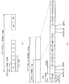
- FIG. 1 illustrates an example of a radio frame structure used in a wireless communication system.
- FIG. 1 (a) shows a frame structure for frequency division duplex (FDD) used in 3GPP LTE / LTE-A system
- FIG. 1 (b) shows TDD (Time used in 3GPP LTE / LTE-A system). It shows a frame structure for Division Duplex.
- FDD frequency division duplex
- TDD Time used in 3GPP LTE / LTE-A system
- a radio frame used in a 3GPP LTE / LTE-A system has a length of 10 ms (307200 Ts) and consists of 10 equally sized subframes (subframes, SFs). Numbers may be assigned to 10 subframes in one radio frame.
- Each subframe has a length of 1 ms and consists of two slots.
- 20 slots in one radio frame may be sequentially numbered from 0 to 19. Each slot is 0.5ms long.
- the time for transmitting one subframe is defined as a transmission time interval (TTI).
- the time resource may be classified by a radio frame number (also called a radio frame index), a subframe number (also called a subframe number), a slot number (or slot index), and the like.
- the radio frame may be configured differently according to the duplex mode. For example, in the FDD mode, since downlink transmission and uplink transmission are divided by frequency, a radio frame includes only one of a downlink subframe or an uplink subframe for a specific frequency band. In the TDD mode, since downlink transmission and uplink transmission are separated by time, a radio frame includes both a downlink subframe and an uplink subframe for a specific frequency band.
- Table 1 illustrates a DL-UL configuration of subframes in a radio frame in the TDD mode.
- D represents a downlink subframe
- U represents an uplink subframe
- S represents a special subframe.
- the singular subframe includes three fields of Downlink Pilot TimeSlot (DwPTS), Guard Period (GP), and Uplink Pilot TimeSlot (UpPTS).
- DwPTS is a time interval reserved for downlink transmission
- UpPTS is a time interval reserved for uplink transmission.
- Table 2 illustrates the configuration of a singular frame.
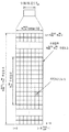
- FIG. 2 illustrates an example of a downlink / uplink (DL / UL) slot structure in a wireless communication system.
- FIG. 2 shows a structure of a resource grid of a 3GPP LTE / LTE-A system. There is one resource grid per antenna port.
- a slot includes a plurality of Orthogonal Frequency Division Multiplexing (OFDM) symbols in a time domain and a plurality of resource blocks (RBs) in a frequency domain.
- An OFDM symbol may mean a symbol period.
- a signal transmitted in each slot may be represented by a resource grid including NDL / ULRB * NRBsc subcarriers and NDL / ULsymb OFDM symbols.
- NDLRB represents the number of resource blocks (RBs) in the downlink slot
- NULRB represents the number of RBs in the UL slot.
- NDLRB and NULRB depend on DL transmission bandwidth and UL transmission bandwidth, respectively.
- NDLsymb represents the number of OFDM symbols in the downlink slot
- NULsymb represents the number of OFDM symbols in the UL slot.
- NRBsc represents the number of subcarriers constituting one RB.
- the OFDM symbol may be called an OFDM symbol, an SC-FDM symbol, or the like according to a multiple access scheme.
- the number of OFDM symbols included in one slot may be variously changed according to the channel bandwidth and the length of a cyclic prefix (CP). For example, in case of a normal CP, one slot includes 7 OFDM symbols, whereas in case of an extended CP, one slot includes 6 OFDM symbols.
- FIG. 2 illustrates a subframe in which one slot consists of 7 OFDM symbols for convenience of description, embodiments of the present invention can be applied to subframes having other numbers of OFDM symbols in the same manner. Referring to FIG. 2, each OFDM symbol includes NDL / ULRB * NRBsc subcarriers in the frequency domain.
- the types of subcarriers may be divided into data subcarriers for data transmission, reference signal subcarriers for transmission of reference signals, null subcarriers for guard band, and direct current (DC) components.
- the null subcarrier for the DC component is a subcarrier left unused and is mapped to a carrier frequency f0 during an OFDM signal generation process or a frequency upconversion process.
- the carrier frequency is also called the center frequency.
- One RB is defined as NDL / ULsymb (e.g., seven) consecutive OFDM symbols in the time domain, and is defined by NRBsc (e.g., twelve) consecutive subcarriers in the frequency domain.
- NRBsc e.g., twelve
- a resource composed of one OFDM symbol and one subcarrier is called a resource element (RE) or tone. Therefore, one RB is composed of NDL / ULsymb * NRBsc resource elements.
- Each resource element in the resource grid may be uniquely defined by an index pair (k, l) in one slot. k is an index assigned from 0 to NDL / ULRB * NRBsc-1 in the frequency domain, and l is an index assigned from 0 to NDL / ULsymb-1 in the time domain.
- Two RBs are referred to as a physical resource block (PRB) pair.
- Two RBs constituting a PRB pair have the same PRB number (or also referred to as a PRB index).
- 3 illustrates a DL subframe structure used in 3GPP LTE / LTE-A system.
- a DL subframe is divided into a control region and a data region in the time domain.
- up to three (or four) OFDM symbols located in the first slot of a subframe correspond to a control region to which a control channel is allocated.
- a resource region available for PDCCH transmission in a DL subframe is called a PDCCH region.
- the remaining OFDM symbols other than the OFDM symbol (s) used as the control region correspond to a data region to which a Physical Downlink Shared CHannel (PDSCH) is allocated.
- PDSCH Physical Downlink Shared CHannel
- a resource region available for PDSCH transmission in a DL subframe is called a PDSCH region.
- Examples of DL control channels used in 3GPP LTE include a physical control format indicator channel (PCFICH), a physical downlink control channel (PDCCH), a physical hybrid ARQ indicator channel (PHICH), and the like.
- the PCFICH is transmitted in the first OFDM symbol of a subframe and carries information about the number of OFDM symbols used for transmission of a control channel within the subframe.
- the PHICH carries a Hybrid Automatic Repeat Request (HARQ) ACK / NACK (acknowledgment / negative-acknowledgment) signal in response to the UL transmission.
- HARQ Hybrid Automatic Repeat Request
- DCI downlink control information
- DCI includes resource allocation information and other control information for the UE or UE group.
- the DCI includes a transmission format and resource allocation information of a downlink shared channel (DL-SCH), a transmission format and resource allocation information of an uplink shared channel (UL-SCH), and a paging channel.
- Paging information on channel, PCH) system information on DL-SCH, resource allocation information of upper layer control message such as random access response transmitted on PDSCH, transmit power control command set for individual UEs in UE group Set), a transmit power control (TPC) command, activation indication information of voice over IP (VoIP), a downlink assignment index (DAI), and the like.
- DL-SCH downlink shared channel
- UL-SCH uplink shared channel
- TPC transmit power control
- VoIP voice over IP
- DAI downlink assignment index
- Transmission format and resource allocation information of a downlink shared channel may also be called DL scheduling information or a DL grant, and may be referred to as an uplink shared channel (UL-SCH).
- the transmission format and resource allocation information is also called UL scheduling information or UL grant.
- the PDCCH is transmitted on an aggregation of one or a plurality of consecutive control channel elements (CCEs).
- CCE is a logical allocation unit used to provide a PDCCH with a coding rate based on radio channel conditions.
- the CCE corresponds to a plurality of resource element groups (REGs). For example, one CCE corresponds to nine REGs and one REG corresponds to four REs.
- REGs resource element groups
- a CCE set in which a PDCCH can be located is defined for each UE.
- the set of CCEs in which a UE can discover its PDCCH is referred to as a PDCCH search space, simply a search space (SS).
- SS search space
- PDCCH candidate An individual resource to which a PDCCH can be transmitted in a search space is called a PDCCH candidate.
- the collection of PDCCH candidates that the UE will monitor is defined as a search space.
- a search space for each DCI format may have a different size, and a dedicated search space and a common search space are defined.
- the dedicated search space is a UE-specific search space and is configured for each individual UE.
- the common search space is set for a plurality of UEs.
- One PDCCH candidate corresponds to 1, 2, 4, or 8 CCEs according to a CCE aggregation level.
- the BS sends the actual PDCCH (DCI) on any PDCCH candidate in the search space, and the UE monitors the search space to find the PDCCH (DCI).
- monitoring means attempting decoding of each PDCCH in a corresponding search space according to all monitored DCI formats.
- the UE may detect its own PDCCH by monitoring the plurality of PDCCHs. Basically, since the UE does not know where its PDCCH is transmitted, every Pframe attempts to decode the PDCCH until every PDCCH of the corresponding DCI format has detected a PDCCH having its own identifier.
- Blind decoding BD
- the BS may transmit data for the UE or the UE group through the data area.
- Data transmitted through the data area is also called user data.
- a physical downlink shared channel (PDSCH) may be allocated to the data area.
- Paging channel (PCH) and downlink-shared channel (DL-SCH) are transmitted through PDSCH.
- the UE may read data transmitted through the PDSCH by decoding control information transmitted through the PDCCH.
- the DCI carried by one PDCCH has a different size and use depending on the DCI format, and its size may vary depending on a coding rate.
- Information indicating to which UE or UE group data of the PDSCH is transmitted, how the UE or UE group should receive and decode PDSCH data, and the like are included in the PDCCH and transmitted.
- a specific PDCCH is masked with a cyclic redundancy check (CRC) with a Radio Network Temporary Identity (RNTI) of "A", a radio resource (eg, frequency location) of "B” and a transmission of "C”.
- RNC Radio Network Temporary Identity
- RNTI Radio Network Temporary Identity
- format information eg, transport block size, modulation scheme, coding information, etc.
- FIG. 4 shows an example of an uplink subframe structure used in a 3GPP LTE / LTE-A system.
- the UL subframe may be divided into a control region and a data region in the frequency domain.
- One or several physical uplink control channels may be allocated to the control region to carry uplink control information (UCI).
- One or several physical uplink shared channels may be allocated to a data region of a UL subframe to carry user data.
- the control region and data region in the UL subframe may also be called a PUCCH region and a PUSCH region, respectively.
- a sounding reference signal (SRS) may be allocated to the data area.
- the SRS is transmitted in the OFDM symbol located at the end of the UL subframe in the time domain and in the data transmission band of the UL subframe, that is, in the data domain, in the frequency domain.
- SRSs of several UEs transmitted / received in the last OFDM symbol of the same subframe may be distinguished according to frequency location / sequence.
- subcarriers having a long distance based on a direct current (DC) subcarrier are used as a control region.
- subcarriers located at both ends of the UL transmission bandwidth are allocated for transmission of uplink control information.
- the DC subcarrier is a component that is not used for signal transmission and is mapped to a carrier frequency f0 during frequency upconversion.
- the PUCCH for one UE is allocated to an RB pair belonging to resources operating at one carrier frequency in one subframe, and the RBs belonging to the RB pair occupy different subcarriers in two slots.
- the PUCCH allocated in this way is expressed as that the RB pair allocated to the PUCCH is frequency hopped at the slot boundary. However, if frequency hopping is not applied, RB pairs occupy the same subcarrier.
- FIG. 5 is a diagram illustrating a subframe for explaining periodic control information. As shown in FIG. 5, a subframe is divided into a region transmitted through a PUSCH and a region transmitted through a physical uplink control channel (PUCCH).
- PUCCH physical uplink control channel
- the BS may be configured to transmit control information to the user equipment at regular intervals.
- the user equipment configured to periodically transmit control information in the uplink periodically transmits CQI / PMI or rank information in a specific subframe. If there is no data to be transmitted at the time point at which the periodic control information is to be transmitted, the user equipment transmits the periodic control information on the uplink through the PUCCH. On the other hand, if there is data to be transmitted at the time to transmit the periodic control information, the user equipment multiplexes the periodic control information with the data and transmits the uplink through the PUSCH.
- Aperiodic control information is triggered by an uplink scheduling grant (BS) transmitted to a UE through a downlink physical downlink control channel (PDCCH) and transmitted to the UE.
- the uplink scheduling grant informs the UE of various information such as a specific frequency and a resource block transmitted in the PUSCH region for transmitting data or aperiodic control information.
- the aperiodic control information may be transmitted only through the PUSCH, and the aperiodic control information is transmitted on the uplink only when the transmission of the aperiodic control information is approved by the uplink scheduling grant received from the BS.
- FIG. 6 illustrates a signal transmission scheme in a normal transmission mode of an FDD system.
- all data are transmitted in units of one subframe.
- the user equipment may re-transmission the same data after 8 TTIs (8 ms in FIG. 5).
- the error may be controlled by transmitting the same data again.
- a method of controlling an error that can be applied to both an FDD system and a TDD system will be described in more detail.
- the BS schedules one or more RBs to a selected UE according to a predetermined scheduling rule, and transmits data to the corresponding UE using the allocated RB.
- scheduling information for downlink transmission is called a DL grant
- a PDCCH carrying a DL grant is called a DL grant PDCCH.
- the BS schedules one or more RBs to a selected UE according to a predetermined scheduling rule, and the UE transmits data in uplink using allocated resources.
- scheduling information for uplink transmission is called a UL grant
- a PDCCH carrying an UL grant is called an UL grant PDCCH.
- ARQ Automatic Repeat ReQuest
- HARQ hybrid ARQ
- Both the ARQ scheme and the HARQ scheme wait for an acknowledgment signal (ACK) after transmitting data (eg, a transport block and a codeword).
- the receiving end sends an acknowledgment signal only when data is properly received, and sends a negative-ACK signal when an error occurs in the received data.
- ACK acknowledgment signal
- the transmitting end receives the ACK signal, it transmits data thereafter, but when receiving the NACK signal, it retransmits the data.
- the ARQ method and the HARQ method differ in processing methods when error data is generated.
- the error data is deleted from the receiving buffer and is not used in subsequent processes.
- the HARQ scheme error data is stored in the HARQ buffer and combined with subsequent retransmission data in order to increase reception success rate.
- the error control is performed using the ARQ method in the RLC (Radio Link Control) layer, and the error control is performed using the HARQ method in the Medium Access Control (MAC) / PHY (Physical) layer.
- the HARQ scheme is divided into synchronous HARQ and asynchronous HARQ according to retransmission timing, and channel-adaptive HARQ and channel-ratio depending on whether the channel state is reflected when determining the amount of retransmission resources. It can be divided into channel-non-adaptive HARQ.
- retransmission timing may be newly scheduled or through additional signaling. That is, the retransmission timing for the error data may vary due to various factors such as channel conditions.
- the channel-adaptive HARQ scheme is a scheme in which a Modulation and Coding Scheme (MCS) for retransmission, the number of RBs, and the like are determined as initially determined.
- MCS Modulation and Coding Scheme
- the channel-adaptive HARQ scheme is a scheme in which the number of MCS, RB, etc. for retransmission is varied according to channel conditions. For example, in the case of the channel-adaptive HARQ scheme, when initial transmission is performed using six RBs, retransmission is also performed using six RBs. On the other hand, in the case of the channel-adaptive HARQ scheme, even if initial transmission is performed using six RBs, retransmission may be performed using a larger or smaller number of RBs depending on the channel state.
- a combination of four HARQs can be achieved, but mainly an asynchronous / channel-adaptive HARQ scheme and a synchronous / channel-adaptive HARQ scheme are used.
- the asynchronous / channel-adaptive HARQ scheme can maximize retransmission efficiency by adaptively varying the retransmission timing and the amount of retransmission resources according to channel conditions, but there is a disadvantage in that the overhead is large, so it is not generally considered for uplink.
- the synchronous / channel-non-adaptive HARQ scheme has the advantage that there is little overhead for the timing and resource allocation for the retransmission because it is promised in the system. There are disadvantages to losing.
- 3GPP LTE (-A) an asynchronous HARQ scheme is used for downlink and a synchronous HARQ scheme is used for uplink.
- FIG. 7 illustrates a resource allocation and retransmission process of the asynchronous DL HARQ scheme.
- the BS transmits scheduling information (Sch. Info) / data (eg, a transport block and a codeword) to the UE (S502) and waits for an ACK / NACK to be received from the UE.
- the BS retransmits scheduling information / data to the UE (S506) and waits for an ACK / NACK to be received from the UE. If an ACK is received from the UE (S508), the HARQ process is terminated. Thereafter, if new data transmission is required, the BS may transmit scheduling information and corresponding data for the new data to the UE (S510).
- a time delay occurs until ACK / NACK is received from the UE and retransmission data is transmitted.
- This time delay occurs because of the time required for channel propagation delay, data decoding / encoding. Therefore, when new data is sent after the current HARQ process is completed, a space delay occurs in data transmission due to a time delay. Accordingly, a plurality of independent HARQ processes are used to prevent a gap in data transmission during the time delay period. For example, when the interval between initial transmission and retransmission is seven subframes, seven independent HARQ processes may be operated to transmit data without a space.
- a plurality of parallel HARQ processes allows UL / DL transmissions to be performed continuously while waiting for HARQ feedback for previous UL / DL transmissions.
- Each HARQ process is associated with a HARQ buffer of a medium access control (MAC) layer.
- MAC medium access control
- Each HARQ process manages state variables related to the number of transmissions of the MAC Physical Data Block (PDU) in the buffer, HARQ feedback for the MAC PDU in the buffer, and the current redundancy version.
- PDU Physical Data Block
- up to eight DL HARQ processes are allocated.
- CA carrier aggregation
- up to eight DL HARQ processes may be allocated for each carrier configured in the UE.
- the maximum number of DL HARQ processes varies according to the UL-DL configuration.
- the maximum number of DL HARQ processes varies according to the TDD UL-DL configuration of the carrier for each carrier configured in the UE.
- Table 3 illustrates the maximum number of asynchronous DL HARQ processes in TDD.
- the maximum number of carrier-specific DL HARQ processes configured in the UE for TDD is determined according to the TDD UL-DL configuration. There may be eight DL / UL HARQ processes for FDD for each carrier set in one UE, and there may be as many HARQ processes according to the TDD UL-DL configuration of the corresponding carrier for each carrier set in one UE.
- 3GPP LTE (-A) FDD eight UL HARQ processes are allocated for each carrier configured in the UE when the MIG does not operate with multiple input multiple output (MIMO).
- MIMO multiple input multiple output
- the number of UL HARQ processes varies according to a UL-DL configuration. Table 4 shows the number of synchronous UL HARQ processes in TDD.
- Table 4 TDD UL-DL configuration Number of HARQ processes for normal HARQ operation Number of HARQ processes for subframe bundling operation 0 7 3 One 4 2 2 2 N / A 3 3 N / A 4 2 N / A 5 One N / A 6 6 3
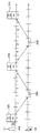
- FIG. 8 illustrates a synchronous UL HARQ process in the case of TDD UL-DL configuration # 1.
- the number in the box in FIG. 6 illustrates a UL HARQ process number.
- 8 illustrates a normal UL HARQ process.
- HARQ process # 1 is involved in subframes # 2, SF # 6, SF # 12, and SF # 16.
- the corresponding UL grant PDCCH and / or PHICH is received in SF # 6 and the corresponding ( Retransmission)
- RTT round trip time
- FIG. 9 illustrates a method of transmitting an uplink signal through a PUSCH in a normal transmission mode.
- eight HARQ processes operate at intervals of eight subframes.
- a user equipment receives a PUSCH scheduling grant signal through a PDCCH in subframe n-4, a PUSCH is transmitted in subframe n and an ACK for the PUSCH transmitted in subframe n + 4. / NACK is received, and if a NACK is received, retransmission is performed in subframe n + 8.
- FIG. 10 is a diagram for describing a subframe bundling transmission scheme in transmitting an uplink signal through a PUSCH in the subframe bundling transmission mode.
- the BS may configure the user equipment to operate in a subframe bundling transmission mode.
- a user device configured to operate in a subframe bundling transmission mode transmits data using a predetermined number of subframes continuous on a time axis.
- FIG. 11 illustrates an example of a method of allocating PDCCH, PUSCH, and PHICH in a subframe bundling transmission mode of an FDD system.
- four HARQ processes operate at intervals of 16 subframes in the subframe bundling transmission mode.
- a PUSCH scheduling grant signal through a PDCCH in subframe n-4
- a PUSCH is transmitted in subframe n.
- retransmission is performed immediately in subframes n + 1, n + 2, and n + 3, and subframe n + 7 (the last PUSCH transmission is called subframe m) for four consecutive PUSCH transmissions.
- ACK / NACK signal is received in subframe m + 4).
- FIG. 12 is a diagram illustrating an example of transmitting an uplink signal through a PUSCH again when a single bundling transmission fails through a PUSCH in a subframe bundling transmission mode of an FDD system.
- a NACK signal is received in subframe n-5, retransmission is performed over four consecutive subframes including subframe n + 4.
- the reason why retransmission is not performed after four subframes after receiving the ACK / NACK is to allow retransmission to be performed at intervals of 16 subframes from the subframe in which the first PUSCH transmission is performed.
- each of the four subframes is configured identically to the subframe in the normal transmission mode, except that the subframe bundling transmission mode is a normal transmission mode in that four consecutive subframes are transmitted on the time axis. It's just different.
- the transmission signal is transmitted in one subframe unit, whereas in the subframe bundling transmission mode, there is only a difference in that the transmission signal is transmitted four times consecutively on the time axis.
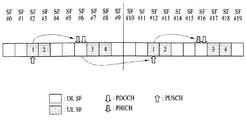
- FIG. 13 illustrates a method of transmitting a signal through a PUSCH, a PHICH, and a PDCCH in a subframe in a subframe bundling transmission mode of a TDD system.
- FIG. 13 exemplifies the case of DL-UL configuration 6 described in Table 1, and shows a case in which radio frame numbers are # 1 to # 3. Subframe numbers # 0 to # 9 are described for each radio frame.
- four consecutive uplink subframes on the time axis are transmitted in a subframe bundling transmission mode in which an uplink signal is transmitted through a PUSCH channel.
- the position of the subframe in which the ACK / NACK signal for the subframe bundling transmission is received may be determined based on the number of the last subframe of the subframe bundling transmission mode. That is, when the number of the last subframe of the subframe bundling transmission mode is m (see FIG. 13), the ACK / NACK signal received through the PHICH channel is received through the subframe m + kPHICH. In this case, kPHICH may be determined by the DL-UL configuration of the TDD system, the value of n, and Table 5 below.
- the DL-UL configuration is 6, and since the number of the last subframe in the subframe bundling transmission mode is m is # 7, the value of kPHICH may be determined to be 4 when referring to Table 5.
- FIG. Accordingly, the ACK / NACK signal for the subframe bundling transmission may be received in subframe # 11 (ie, subframe # 1 of radio frame # 2), which is after 4 subframes in subframe # 7.
- the location of the reception subframe of the ACK / NACK signal on the PHICH channel may have the following relationship with the subframe in which the UL grant for the next subframe bundling transmission is received. If the number of subframes receiving the UL grant for any subframe bundling transmission is n, the subframe in which the ACK / NACK is received for the previous subframe bundling transmission is the subframe n-iPHICH and iPHICH is shown in Table 6 below.
- the first subframe of subframe bundling for this is defined as a subframe n + k PDCCH , and k PDCCH may be determined by Table 7 below.
- the first frame of the subframe bundling transmission for the UL grant received in subframe # 9 of radio frame # 2 is subframe # 4 of radio frame # 3 plus 5 in subframe # 4 (subframe of radio frame # 2). # 14).
- the uplink / downlink configuration of the subframe is changed up or down by the dynamic uplink / downlink configuration, and the uplink / downlink of the subframe is performed through band swapping.
- Band swapping means that a frequency used for uplink is temporarily used for downlink. Or vice versa.
- the dynamic uplink / downlink configuration is described in the FDD system, but it is obvious that this includes the case where the uplink / downlink configuration is changed by band swapping.
- embodiments of the present invention propose a method of redefining such an allocation rule of a transport channel.
- uplink / downlink configuration for a subframe used for subframe bundling transmission is changed by dynamic DL-UL configuration in FDD and TDD systems
- four uplink subframes followed by the uplink / downlink configuration are changed.
- the BS will control subframe bundling transmission to the UE and uplink / downlink configuration for the UE by higher layer signaling or the like, it can know which subframes will be bundled. Accordingly, the BS can know in which subframes uplink data according to the same uplink grant will be received continuously.
- a specific example of such a proposal will be described with reference to FIG. 14 and the FDD system with reference to FIG. 15.
- FIG. 14 is a diagram illustrating an example of a method of redefining an allocation rule of a PDCCH and a PUSCH transport channel in an FDD system according to an embodiment of the present invention.
- FIG. 14 illustrates subframe configuration before dynamic uplink / downlink configuration
- (b) illustrates subframe configuration after dynamic uplink / downlink configuration.
- the first subframe of the subframe bundling transmission for the received UL grant is subframe n + 4. Therefore, when the UL grant is received in the subframe having the subframe number # 1 as in the example shown in FIG. 14 (a), the first subframe of the subframe bundling transmission starts in the subframe # 5 added by 4 .
- FIG. 14 (b) shows the dynamic uplink / downlink configuration after setting the subframe # 5 and # 6 configuration from the uplink to the downlink in the subframe configuration of FIG. 14 (a). Holding it.
- the user equipment may bundle four uplink subframes following the subframe # 6 and use the subframe bundling transmission mode.
- the first subframe of the subframe bundling transmission may not start in subframe # 5 but may start in subframe # 7.
- the position of the UL grant corresponding thereto is also shown in FIG.
- the reception time is changed to the second reception time of FIG. 14B.
- the subframe used for the subframe bundling transmission is changed by the dynamic uplink / downlink configuration as described above, after the first reception time and the time of receiving the UL grant before the change, It is further proposed to determine a second reception time, which is a time for receiving the UL grant, and to perform decoding at both reception points.
- the base station when the base station determines when to transmit a UL grant to the user equipment, the base station includes at least one of a time point before the change of the subframe setting (first transmission time point) and a time point after the change (second transmission time point).
- the UL grant may be transmitted by selecting a time point of the.
- the base station may determine the current communication environment of the wireless communication system.
- the communication environment may include a quality state of a currently connected network, a transmission / reception rate of data, and / or a number of other user devices sharing the same transmission resource. That is, in the example shown in FIG. 14, in one embodiment of the present invention, the user equipment may perform subframe bundling transmission in the state of FIG. 14 (b) by dynamic uplink / downlink configuration in the state of FIG. 14 (a).
- the frame position is changed, it is proposed to perform blind detection in both the first frame subframe # 1 and the second frame subframe # 3.
- the user equipment may perform subframe bundling transmission on the PUSCH channel based on the detected UL grant.
- subframe bundling transmission may be performed on the PUSCH channel based on a UL grant that is later in time among the detected UL grants.
- FIG. 14 has described an embodiment of the present invention for an FDD system.
- FIG. 15 an embodiment of the present invention will be described.
- FIG. 15 illustrates an example of a method of redefining an allocation rule of a PDCCH and a PUSCH transport channel in a TDD system according to an embodiment of the present invention.
- FIG. 15A illustrates subframe configuration before dynamic uplink / downlink configuration
- (b) illustrates subframe configuration after dynamic uplink / downlink configuration.
- the DL-UL configuration of the TDD system is 6, and the configuration of the subframe # 7 of the radio frame # 1 is changed from the uplink subframe to the downlink subframe by the dynamic uplink / downlink configuration. It is shown.
- n which is the number of the first subframe of the subframe bundling transmission and the DL-UL configuration
- n which is the number of the first subframe of the subframe bundling transmission and the DL-UL configuration
- Table 7 an UL grant is received in subframe # 0. You can see that.
- the position of the subframe used for subframe bundling transmission is changed. That is, when at least one uplink / downlink configuration of a predetermined number of consecutive subframes is changed from uplink to downlink, the number of the changed subframes is transmitted in the order of closest order among subsequent uplink subframes.
- the position of the subframe of the uplink signal can be changed.
- the subframe bundling transmission may be changed to subframe # 4 of the closest radio frame # 2 among the subsequent subframes used in the subframe bundling transmission.
- the number of the first subframe among the subframes used for the subframe bundling transmission is changed from # 7 to # 8.
- the reception point of the UL grant may be redefined by dividing the case where the k PDCCH value is defined in Table 7 and the case where it is not defined. That is, the user equipment determines the reception point of the UL grant by dividing the case where the k PDCCH value is defined in Table 7 and the case where the subframe n 'is not defined.
- the user equipment may determine the subframe n'-k PDCCH as a reception point of the UL grant.
- the user equipment may determine subframe # 4 of the radio frame immediately before the n'-k PDCCH as a reception point of the UL grant.
- the UE determines the third reception time of the UL grant based on the subframe n before the change and the UL grant based on the subframe n 'after the change. Determine a fourth reception point of time. Thereafter, the user equipment determines the UL subframe as the reception point of the UL grant among the downlink subframes existing within the third and fourth reception time points.
- the user equipment may determine that the UL grant is received in the subframe # 0.
- the user equipment determines the fourth reception time based on the subframe # 8 in which n 'is # 8 after changing the dynamic uplink / downlink configuration, and the subframe # 4 in subframe n'-4 is determined by the UL grant. 4 can be determined as a reception time.
- the user equipment may identify downlink subframes among subframes within the third and fourth reception time points as subframes # 0 and # 1.
- the user equipment can determine subframe # 0, which is the most recent subframe among the two subframes, as a reception subframe of the UL grant.
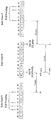
- FIG. 16 illustrates an example of a method of redefining an allocation rule of a PUSCH and a PHICH transport channel in an FDD system according to an embodiment of the present invention.
- FIG. 16A illustrates subframe configuration before dynamic uplink / downlink configuration
- (b) illustrates subframe configuration after dynamic uplink / downlink configuration.
- subframe # 1 to # 4 are used by subframe bundling transmission in FIG. 16 (a).
- the user equipment may determine subframe m + 4 as a reception time through the PHICH of the ACK / NACK signal for the subframe bundling transmission.
- the user equipment may receive the ACK / NACK signal in subframe # 8 of m + 4.
- the configuration of the subframe # 1 is changed from uplink to downlink due to the dynamic uplink / downlink configuration.
- the following four uplink subframes are used for the subframe bundling transmission. Therefore, in this case, since the subframe # 1 has been changed from uplink to downlink, the user equipment can use the following subframes # 2 to # 5 for subframe bundling transmission.
- the user equipment may determine the subframe m' + 4 as the reception time of the ACK / NACK through the PHICH channel. That is, as shown in the example of FIG. 16B, when m 'is # 5, the user equipment may receive an ACK / NACK signal in subframe # 9 of m' + 4.
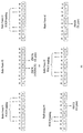
- FIG. 17 illustrates an example of a method of redefining allocation rules of a PUSCH and a PHICH transport channel in a TDD system according to an embodiment of the present invention.
- FIG. 17A illustrates subframe configuration before dynamic uplink / downlink configuration
- (b) illustrates subframe configuration after dynamic uplink / downlink configuration.
- subframes # 2 to # 4 and # 7 are used by subframe bundling transmission in FIG. 17 (a).
- the user equipment determines the reception time of the ACK / NACK signal on the basis of the most recent subframe among the subframes used for the subframe bundling transmission. Therefore, when determining based on subframe # 7, which is the most recent subframe among the subframes used for the subframe bundling transmission, the user equipment determines the reception time of the ACK / NACK signal corresponding to the subframe bundling transmission. It may be determined as subframe # 1 of 2.
- FIG. 17B illustrates an example in which the configuration of the subframe # 5 of the radio frame # 1 in the state of FIG. 17A is changed from the downlink to the uplink by the dynamic uplink / downlink configuration.
- a downlink subframe existing between uplink subframes used for subframe bundling transmission is changed from downlink to uplink by dynamic uplink / downlink configuration. If so, the changed uplink subframe may be used for the subframe bundling transmission mode.
- a description with reference to the example of FIG. 17 is as follows. Subframes # 2, # 3, # 4, and # 7 were used for subframe bundling transmission and then existed between subframes # 2, # 3, # 4, and # 7 by dynamic uplink / downlink configuration. The configuration of link subframe # 5 has been changed to uplink. Then, the user equipment can use the subframe # 5 changed to uplink instead of the subframe # 7 used in the subframe bundling transmission mode. Therefore, referring to FIG. 17B, it can be seen that subframes # 2 to # 5 are used in the subframe bundling transmission mode.
- the changed m when the number of the most recent subframe among the subframes used in the subframe bundling transmission mode is changed to m 'by the dynamic uplink / downlink configuration, the changed m
- the kPHICH for ' is defined in Table 5 and not defined, it is possible to determine the reception time of the ACK / NACK signal.
- the user equipment may receive an ACK / NACK signal for this subframe bundling transmission mode in subframe m' + kPHICH.
- the value of kPHICH can be confirmed to be 6 according to Table 5. Accordingly, in this case, the user equipment is received in subframe # 10 (that is, subframe # 0 of the next radio frame) in which the ACK / NACK signal for the subframe bundling transmission mode is # 4 + 6.
- the user equipment determines the fifth reception time based on the subframe m before the change and based on the subframe m' after the change. After determining the sixth reception time, an ACK / NACK signal may be received in a subframe temporally preceding the fifth reception time and the sixth reception time.
- the case of FIG. 17B may be considered.
- the number of the most recent subframe according to the subframe bundling transmission mode is changed to # 5 by the dynamic uplink / downlink configuration.
- the subframe number is # 5
- the value of kPHICH is not defined. Therefore, in this case, the user equipment may determine the fifth reception time and the sixth reception time, and receive an ACK / NACK signal in a subframe temporally preceding the fifth reception time and the sixth reception time.
- the user equipment may determine the fifth reception time based on the subframe number m before the change. According to Table 5, DL-UL configuration is 6, when determining the value of kPHICH for the subframe number # 7 before the change, it can be confirmed that 4. Accordingly, the user equipment can determine subframe # 11 (subframe # 1 of the next radio frame) of # 7 + kPHICH as the fifth reception time point (see FIG. 17A).
- the user device may determine the subframe number m 'as a reference.
- the user equipment may determine the sixth reception time as a subframe at the time of adding a predetermined value from m '. For example, the user equipment may determine the sixth reception time as the subframe m '+ 4.
- subframe # 11 subframe # 1 of radio frame # 2, which is the next radio frame
- subframe m '+ 4 subframe # 1 of radio frame # 1).
- an ACK / NACK signal may be received in subframe # 9, which is a subframe preceding the temporal frame.
- a downlink subframe existing between uplink subframes used for subframe bundling transmission is configured for the subframe by dynamic uplink / downlink configuration. Even if the configuration is changed from downlink to uplink, the changed uplink subframe may not be used in the subframe bundling transmission mode. That is, in the above-described embodiment with reference to FIG. 17, the case where the position of the uplink subframes used for subframe bundling transmission is changed by the dynamic uplink / downlink configuration has been described.
- the user equipment in the embodiment proposes not to change the uplink subframes used for subframe bundling transmission.
- FIG. 18 illustrates another example of a method of redefining allocation rules of a PUSCH and a PHICH transport channel in a TDD system according to an embodiment of the present invention.
- FIG. 18A illustrates subframe configuration before dynamic uplink / downlink configuration
- (b) illustrates subframe configuration after dynamic uplink / downlink configuration.
- subframes # 2 to # 4 and # 7 are used by subframe bundling transmission as in FIG. 17A.
- the user equipment sends an ACK / NACK signal corresponding to the subframe bundling transmission to the subframe of the radio frame # 2. It can be received in frame # 1.
- FIG. 18B An example of a case in which the configuration of the subframe # 5 of the radio frame # 1 in the state of FIG. 18A is changed from the downlink to the uplink by the dynamic uplink / downlink configuration is shown in FIG. 18B.
- subframe # 5 which is a subframe changed from downlink to uplink
- subframe # 7 which is the most recent subframe used in the subframe bundling mode before the configuration change
- subframe # 7 which is the most recent subframe used in the subframe bundling mode before the configuration change
- the user device has an advantage in that the previously determined reception position can be used as it is.
- the subframe configuration is changed from downlink to uplink by dynamic uplink / downlink configuration.
- the embodiment of the present invention can also be applied to the case of changing from uplink to downlink.
- the present invention proposes not to change the reception point of the ACK / NACK signal or the reception point of the UL grant through the PDCCH channel.
- the user equipment when the configuration of a subframe used for subframe bundling transmission is changed from uplink to downlink, the user equipment does not transmit in the changed subframe and does not perform additional transmission in another uplink subframe. Do not. That is, by reducing the number of subframes used by the user equipment for subframe bundling transmission, it is possible to maintain a time point of receiving an ACK / NACK signal or a PDCCH channel.
- the user equipment excludes subframes that can be changed in subframe configuration by dynamic uplink / downlink configuration except for bundling transmission, and performs bundling only in subframes in which subframe configuration cannot be changed. Can be done.
- both the BS and the user equipment have previously defined which subframes can be changed in uplink / downlink. These subframes perform bundling only in unmodifiable subframes except in a bundling operation. For example, the case of changing from Fig. 17 (a) to (b). Although the configuration of the subframe # 5 is changed from the downlink to the uplink, bundling transmission is possible, the user equipment does not use the subframe # 5 and subframes the subframes # 2, # 3, # 4, and # 7. Used in frame bundling transmission mode.
- the subframe bundling transmission mode is used to improve reliability between the base station and the user equipment when the channel situation is poor.
- one subframe bundling transmission is composed of four uplink subframes. Since each subframe is the same as the transmission in the normal transmission mode, any one subframe of the subframe bundling transmission mode is normally received. If necessary, the information transmitted through the remaining subframes is not needed. If so, it is efficient to stop the transmission on the remaining subframes and use the resources for other purposes.
- the transmission is successfully performed by any one of the subframes used in the subframe bundling transmission mode, it will not transmit the same signal on the additional PUSCH channel. I would suggest.
- the reception time of the ACK / NACK signal may be determined based on the subframe.
- FIG. 19 illustrates an example of a method of defining a response channel for a subframe bundling transmission mode in an FDD system.
- FIG. 19A illustrates a first example of a method of defining a response channel
- FIG. 19B illustrates a second example of a method of defining a response channel.
- both PUSCH channels are transmitted using subframe bundling transmission mode in subframes # 1 to # 4, and transmission in subframe # 2, which is a second transmission, is performed by a base station.
- a base station which is a second transmission
- the base station proposes to transmit an ACK / NACK signal (or UL grant signal), which is a response thereto, based on the m subframe, which is the successfully transmitted subframe # 2 number.
- the base station since the PUSCH channel transmitted in subframe # 2 has been successfully transmitted, the base station transmits an ACK / NACK signal in subframe # 6, which is a subframe # 2 + 4 based on subframe # 2. Can be transmitted.
- the base station instead of omitting the ACK / NACK signal, the base station immediately transmits a UL grant signal to increase resource utilization. That is, the base station may transmit the UL grant in the subframe at the time of transmitting the ACK / NACK signal as in the second example 17 (b).
- the UL grant is used instead of the ACK / NACK signal, the NDI field of the PDCCH is checked, and if the value of the field is different from the value of the previously received field, the user equipment determines that it is an ACK. If not toggled, it can be determined as NACK.
- the user equipment that receives the UL grant and the toggled NDI field instead of the ACK signal may confirm that the PUSCH is properly transmitted and perform the next subframe bundling transmission through the PUSCH channel.
- the UL grant signal instead of the ACK signal there is an advantage in terms of resource utilization than the first example of receiving the UL grant again after the ACK signal. This is because delays up to "retransmission” / "new transmission” can be reduced, and in some cases, it is possible to utilize an uplink subframe among other subframes used for subframe bundling transmission.
- the FDD system is taken as an example, but the same concept may be applied to the TDD system. Description of this will be described with reference to FIG. 20.
- the user equipment in the TDD system proposes not to transmit on an additional PUSCH channel if transmission is successfully performed by any one of subframes used in the subframe bundling transmission mode.
- 20 (a) is a diagram illustrating a channel allocation method of a PUSCH, a PHICH, and a PDCCH according to a general method according to Tables 5 to 7.
- the subframes used for the first subframe bundling transmission include subframes # 2, # 3, # 7, and # 8 of radio frame # 1. It is used.
- Subframes # 2, # 3, # 7 and # 8 of the radio frame # 3 are used as the subframe used for the second subframe bundling transmission.
- an ACK / NACK signal is received in subframe # 4 of radio frame # 2.
- the UL grant signal for the second subframe bundling transmission is received in subframe # 6 of radio frame # 2.
- FIG. 20 (b) shows an embodiment to which the method of defining a response channel proposed in the embodiment of the present invention is applied.
- transmission is performed through subframes # 2 and # 3 by subframe bundling transmission, and that a PUSCH channel transmitted in subframe # 3 is normally transmitted to a base station.
- the base station transmits an ACK / NACK signal (or a UL grant signal instead of the ACK / NACK signal), which is a response thereto, based on the subframe # 3 position normally transmitted during the subframe bundling transmission.
- FIG. 20 (b) transmits a UL grant instead of an ACK / NACK signal in response to a subframe bundling transmission. This is to increase resource efficiency as described with reference to FDD in FIG. 19.
- the user equipment was supposed to perform the remaining transmission by subframe bundling transmission in subframes # 7 and # 8, but does not perform the remaining subframe bundling transmission by receiving the UL grant in subframe # 6, and immediately transmits the next subframe bundling. You can proceed.
- the base station determines the transmission time of the ACK / NACK signal (or UL grant instead of the ACK / NACK signal) for the subframe bundling transmission, the base station is determined based on the subframe # 3 that is normally transmitted. As such, when determining the response time (the reception time of the ACK / NACK signal or the UL grant instead of the ACK / NACK signal) based on the subframe # 3, the base station transmits the UL grant in the subframe # 6. Therefore, the user equipment can determine the time point of the second subframe bundling transmission again based on the UL grant received in the subframe # 6. The user equipment can determine the start time of the second subframe bundling transmission as the subframe # 2 of the radio frame # 2 as shown in FIG. 20 (b).
- FIG. 20 (a) not by the response channel definition of the present invention and FIG. 20 (b) by the response channel definition of the present invention in the case of FIG. 20 (a), two subs are performed during three radio frames.
- frame bundling transmission has been performed, it can be seen in FIG. 20 (b) that two subframe bundling transmissions have been performed during two radio frames. Therefore, according to this embodiment of the present invention, there is an advantage that more information can be efficiently transmitted using less radio resources.
- Embodiments of the present invention may be used in a base station or user equipment or other equipment in a wireless communication system.
Landscapes
- Engineering & Computer Science (AREA)
- Computer Networks & Wireless Communication (AREA)
- Signal Processing (AREA)
- Mobile Radio Communication Systems (AREA)
Priority Applications (2)
| Application Number | Priority Date | Filing Date | Title |
|---|---|---|---|
| CN201380004959.6A CN104040913B (zh) | 2012-01-06 | 2013-01-07 | 用于分配关于上行链路绑定的信道的方法和设备 |
| US14/364,291 US9504033B2 (en) | 2012-01-06 | 2013-01-07 | Method and apparatus for allocating channels related to uplink bundling |
Applications Claiming Priority (2)
| Application Number | Priority Date | Filing Date | Title |
|---|---|---|---|
| US201261583616P | 2012-01-06 | 2012-01-06 | |
| US61/583,616 | 2012-01-06 |
Publications (1)
| Publication Number | Publication Date |
|---|---|
| WO2013103280A1 true WO2013103280A1 (ko) | 2013-07-11 |
Family
ID=48745302
Family Applications (1)
| Application Number | Title | Priority Date | Filing Date |
|---|---|---|---|
| PCT/KR2013/000105 WO2013103280A1 (ko) | 2012-01-06 | 2013-01-07 | 상향링크 번들링 관련 채널의 할당 방법 및 장치 |
Country Status (3)
| Country | Link |
|---|---|
| US (1) | US9504033B2 (zh) |
| CN (1) | CN104040913B (zh) |
| WO (1) | WO2013103280A1 (zh) |
Cited By (3)
| Publication number | Priority date | Publication date | Assignee | Title |
|---|---|---|---|---|
| CN107431948A (zh) * | 2015-04-24 | 2017-12-01 | 夏普株式会社 | 终端装置、基站装置、集成电路及通信方法 |
| WO2019213889A1 (en) * | 2018-05-10 | 2019-11-14 | Qualcomm Incorporated | Uplink configuration change request |
| US10721759B2 (en) | 2013-09-27 | 2020-07-21 | Huawei Technologies Co., Ltd. | Method for transmitting uplink data, user equipment, and base station |
Families Citing this family (15)
| Publication number | Priority date | Publication date | Assignee | Title |
|---|---|---|---|---|
| EP2826288B1 (en) * | 2012-03-16 | 2018-12-05 | Interdigital Patent Holdings, Inc. | Random access procedures in wireless systems |
| WO2014005632A1 (en) * | 2012-07-04 | 2014-01-09 | Nokia Siemens Networks Oy | Method and apparatus for signalling of harq timing at ul/dl subframe reconfiguration |
| JP6284486B2 (ja) * | 2012-11-26 | 2018-02-28 | パナソニック インテレクチュアル プロパティ コーポレーション オブ アメリカPanasonic Intellectual Property Corporation of America | 端末装置及び再送方法 |
| US9538503B2 (en) * | 2013-03-28 | 2017-01-03 | Samsung Electronics Co., Ltd. | Aggregation of FDD and TDD cells |
| US10305626B2 (en) | 2013-04-05 | 2019-05-28 | Qualcomm Incorporated | Enhanced transmission time interval bundling design for machine type communications |
| CN104104486A (zh) * | 2013-04-12 | 2014-10-15 | 北京三星通信技术研究有限公司 | 一种支持多子帧调度上行数据传输的方法和设备 |
| CN104349459B (zh) * | 2013-07-25 | 2019-04-19 | 索尼公司 | 在无线通信系统中进行动态上行配置的方法、基站和终端 |
| US20150043434A1 (en) * | 2013-08-08 | 2015-02-12 | Sharp Laboratories Of America, Inc. | Systems and methods for subframe bundling |
| US10142064B2 (en) * | 2013-09-17 | 2018-11-27 | Intel IP Corporation | Techniques and configurations associated with machine type communication in enhanced coverage mode |
| US10143005B2 (en) | 2014-11-07 | 2018-11-27 | Qualcomm Incorporated | Uplink control resource allocation for dynamic time-division duplex systems |
| US10313066B2 (en) | 2015-04-22 | 2019-06-04 | Lg Electronics Inc. | Method for transmitting and receiving data channel and LC device |
| WO2017028052A1 (zh) * | 2015-08-14 | 2017-02-23 | 华为技术有限公司 | 一种信息的传输方法和基站以及用户设备 |
| WO2017177440A1 (zh) * | 2016-04-15 | 2017-10-19 | 富士通株式会社 | 状态指示的传输装置、方法以及通信系统 |
| CN109076056B (zh) * | 2016-04-21 | 2022-07-12 | 瑞典爱立信有限公司 | 在终端设备和网络设备中使用的方法及相关联的设备 |
| WO2018174680A1 (ko) * | 2017-03-24 | 2018-09-27 | 엘지전자 주식회사 | 무선 통신 시스템에서 harq 프로세스를 수행하는 방법 및 이를 위한 장치 |
Citations (4)
| Publication number | Priority date | Publication date | Assignee | Title |
|---|---|---|---|---|
| KR20100002114A (ko) * | 2008-06-24 | 2010-01-06 | 엘지전자 주식회사 | 상향링크 신호 전송 방법 |
| KR20100021475A (ko) * | 2007-06-18 | 2010-02-24 | 텔레호낙티에볼라게트 엘엠 에릭슨(피유비엘) | Tti 번들링에 의한 업링크 송신 강화 |
| KR20100139062A (ko) * | 2008-03-24 | 2010-12-31 | 지티이 (유에스에이) 인크. | Lte/τdd 시스템에서의 다운링크/업링크 할당 비율의 동적 조정 및 시그널링 |
| KR20110055014A (ko) * | 2009-11-19 | 2011-05-25 | 에스케이 텔레콤주식회사 | 고속 무선통신 시스템에서 상향링크와 하향링크의 전환점 변경을 통한 동적 자원 할당 방법 및 그 시스템 |
Family Cites Families (5)
| Publication number | Priority date | Publication date | Assignee | Title |
|---|---|---|---|---|
| US7613157B2 (en) | 2005-08-30 | 2009-11-03 | Interdigital Technology Corporation | Wireless communication method and apparatus for processing enhanced uplink scheduling grants |
| CN101499894B (zh) * | 2008-02-01 | 2011-04-20 | 大唐移动通信设备有限公司 | 一种时分双工系统中的上行调度方法 |
| US20090285122A1 (en) | 2008-04-21 | 2009-11-19 | Texas Instruments Incorporated | Uplink control for time-division duplex with asymmetric assignment |
| EP2230789B1 (en) | 2008-12-30 | 2013-02-20 | HTC Corporation | Method of distinguishing hybrid automatic repeat request processes and related communication device |
| US8768263B2 (en) * | 2010-12-01 | 2014-07-01 | Qualcomm Incorporated | Determining an uplink control path with blind decoding |
-
2013
- 2013-01-07 US US14/364,291 patent/US9504033B2/en active Active
- 2013-01-07 WO PCT/KR2013/000105 patent/WO2013103280A1/ko active Application Filing
- 2013-01-07 CN CN201380004959.6A patent/CN104040913B/zh not_active Expired - Fee Related
Patent Citations (4)
| Publication number | Priority date | Publication date | Assignee | Title |
|---|---|---|---|---|
| KR20100021475A (ko) * | 2007-06-18 | 2010-02-24 | 텔레호낙티에볼라게트 엘엠 에릭슨(피유비엘) | Tti 번들링에 의한 업링크 송신 강화 |
| KR20100139062A (ko) * | 2008-03-24 | 2010-12-31 | 지티이 (유에스에이) 인크. | Lte/τdd 시스템에서의 다운링크/업링크 할당 비율의 동적 조정 및 시그널링 |
| KR20100002114A (ko) * | 2008-06-24 | 2010-01-06 | 엘지전자 주식회사 | 상향링크 신호 전송 방법 |
| KR20110055014A (ko) * | 2009-11-19 | 2011-05-25 | 에스케이 텔레콤주식회사 | 고속 무선통신 시스템에서 상향링크와 하향링크의 전환점 변경을 통한 동적 자원 할당 방법 및 그 시스템 |
Non-Patent Citations (1)
| Title |
|---|
| "3GPP; TSGRAN; E-UTRA; MAC protocol specification (Release 9)", 3GPP TS 36,321 V9.3.0, June 2010 (2010-06-01) * |
Cited By (4)
| Publication number | Priority date | Publication date | Assignee | Title |
|---|---|---|---|---|
| US10721759B2 (en) | 2013-09-27 | 2020-07-21 | Huawei Technologies Co., Ltd. | Method for transmitting uplink data, user equipment, and base station |
| EP3429297B1 (en) * | 2013-09-27 | 2021-04-28 | Huawei Technologies Co., Ltd. | Method for transmitting uplink data and corresponding apparatus and computer-readable storage medium |
| CN107431948A (zh) * | 2015-04-24 | 2017-12-01 | 夏普株式会社 | 终端装置、基站装置、集成电路及通信方法 |
| WO2019213889A1 (en) * | 2018-05-10 | 2019-11-14 | Qualcomm Incorporated | Uplink configuration change request |
Also Published As
| Publication number | Publication date |
|---|---|
| CN104040913A (zh) | 2014-09-10 |
| US20140362796A1 (en) | 2014-12-11 |
| CN104040913B (zh) | 2017-03-15 |
| US9504033B2 (en) | 2016-11-22 |
Similar Documents
| Publication | Publication Date | Title |
|---|---|---|
| WO2013103280A1 (ko) | 상향링크 번들링 관련 채널의 할당 방법 및 장치 | |
| WO2018038418A1 (ko) | 무선 통신 시스템에서 상향링크 전송을 위한 방법 및 이를 위한 장치 | |
| WO2017135713A1 (ko) | 무선 통신 시스템에서 무선 신호 송수신 방법 및 장치 | |
| WO2017171516A1 (ko) | 무선 통신 시스템에서 상향링크 제어 정보의 전송 또는 수신 방법 및 이를 위한 장치 | |
| WO2017135745A1 (ko) | 무선 통신 시스템에서 상향링크 제어 정보의 맵핑, 전송, 또는 수신 방법 및 이를 위한 장치 | |
| WO2018088857A1 (ko) | 무선 통신 시스템에서 상향링크 신호를 전송하기 위한 방법 및 이를 위한 장치 | |
| WO2017078326A1 (ko) | 무선 통신 시스템에서 상향링크 제어 채널 전송 방법 및 이를 위한 장치 | |
| WO2017217797A1 (ko) | 무선 통신 시스템에서 무선 신호 송수신 방법 및 장치 | |
| WO2015065111A1 (en) | Method and apparatus for simultaneous transmission of downlink harq-ack and sr | |
| WO2016093618A1 (ko) | 반송파 집성을 지원하는 무선 통신 시스템에서 단말의 채널 상태 정보 보고 방법 및 이를 위한 장치 | |
| WO2017043916A1 (ko) | 무선 통신 시스템에서 신호의 전송 방법 및 장치 | |
| WO2013191360A1 (ko) | 신호 송수신 방법 및 이를 위한 장치 | |
| WO2014185659A1 (ko) | 셀 커버리지 확장 영역 위치한 mtc 기기의 시스템 정보 수신 방법 | |
| WO2018203732A1 (ko) | 무선 통신 시스템에서 상향링크 신호를 전송하기 위한 방법 및 이를 위한 장치 | |
| WO2015190844A1 (en) | Harq procedure and frame structure for lte cells on unlicensed spectrum | |
| WO2019156466A1 (ko) | 무선 통신 시스템에서 신호를 송신 또는 수신하는 방법 및 이를 위한 장치 | |
| WO2015115818A1 (ko) | Harq ack/nack 전송방법 및 장치 | |
| WO2016028103A1 (ko) | 무선 통신 시스템에서 신호 전송 방법 및 장치 | |
| WO2015012665A1 (ko) | Mtc를 위한 신호 전송 방법 및 이를 위한 장치 | |
| WO2012124996A2 (ko) | 신호 송수신 방법 및 이를 위한 장치 | |
| WO2013009043A9 (ko) | 무선 통신 시스템에서 하향링크 harq 송수신 방법 및 장치 | |
| WO2012112008A2 (en) | Mobile communication system and channel transmission/reception method thereof | |
| WO2012124969A2 (ko) | 신호 송수신 방법 및 이를 위한 장치 | |
| WO2011007985A2 (ko) | 무선 통신 시스템에서 수신 장치가 제어 정보를 전송하는 방법 | |
| WO2013129868A1 (en) | Mobile communication system and channel transmission/reception method thereof |
Legal Events
| Date | Code | Title | Description |
|---|---|---|---|
| 121 | Ep: the epo has been informed by wipo that ep was designated in this application |
Ref document number: 13733750 Country of ref document: EP Kind code of ref document: A1 |
|
| WWE | Wipo information: entry into national phase |
Ref document number: 14364291 Country of ref document: US |
|
| NENP | Non-entry into the national phase |
Ref country code: DE |
|
| 122 | Ep: pct application non-entry in european phase |
Ref document number: 13733750 Country of ref document: EP Kind code of ref document: A1 |