WO2013100593A1 - 유중가스 함량비를 통한 유입변압기의 내부결함 진단방법 - Google Patents
유중가스 함량비를 통한 유입변압기의 내부결함 진단방법 Download PDFInfo
- Publication number
- WO2013100593A1 WO2013100593A1 PCT/KR2012/011506 KR2012011506W WO2013100593A1 WO 2013100593 A1 WO2013100593 A1 WO 2013100593A1 KR 2012011506 W KR2012011506 W KR 2012011506W WO 2013100593 A1 WO2013100593 A1 WO 2013100593A1
- Authority
- WO
- WIPO (PCT)
- Prior art keywords
- oil
- defect
- internal
- gas
- region
- Prior art date
- Legal status (The legal status is an assumption and is not a legal conclusion. Google has not performed a legal analysis and makes no representation as to the accuracy of the status listed.)
- Ceased
Links
Images


Classifications
-
- G—PHYSICS
- G01—MEASURING; TESTING
- G01R—MEASURING ELECTRIC VARIABLES; MEASURING MAGNETIC VARIABLES
- G01R31/00—Arrangements for testing electric properties; Arrangements for locating electric faults; Arrangements for electrical testing characterised by what is being tested not provided for elsewhere
- G01R31/40—Testing power supplies
-
- G—PHYSICS
- G01—MEASURING; TESTING
- G01N—INVESTIGATING OR ANALYSING MATERIALS BY DETERMINING THEIR CHEMICAL OR PHYSICAL PROPERTIES
- G01N33/00—Investigating or analysing materials by specific methods not covered by groups G01N1/00 - G01N31/00
- G01N33/0004—Gaseous mixtures, e.g. polluted air
-
- G—PHYSICS
- G01—MEASURING; TESTING
- G01N—INVESTIGATING OR ANALYSING MATERIALS BY DETERMINING THEIR CHEMICAL OR PHYSICAL PROPERTIES
- G01N33/00—Investigating or analysing materials by specific methods not covered by groups G01N1/00 - G01N31/00
- G01N33/26—Oils; Viscous liquids; Paints; Inks
-
- G—PHYSICS
- G01—MEASURING; TESTING
- G01N—INVESTIGATING OR ANALYSING MATERIALS BY DETERMINING THEIR CHEMICAL OR PHYSICAL PROPERTIES
- G01N33/00—Investigating or analysing materials by specific methods not covered by groups G01N1/00 - G01N31/00
- G01N33/26—Oils; Viscous liquids; Paints; Inks
- G01N33/28—Oils, i.e. hydrocarbon liquids
- G01N33/2835—Specific substances contained in the oils or fuels
- G01N33/2841—Gas in oils, e.g. hydrogen in insulating oils
-
- H—ELECTRICITY
- H01—ELECTRIC ELEMENTS
- H01F—MAGNETS; INDUCTANCES; TRANSFORMERS; SELECTION OF MATERIALS FOR THEIR MAGNETIC PROPERTIES
- H01F27/00—Details of transformers or inductances, in general
- H01F27/08—Cooling; Ventilating
- H01F27/10—Liquid cooling
- H01F27/12—Oil cooling
-
- H—ELECTRICITY
- H01—ELECTRIC ELEMENTS
- H01F—MAGNETS; INDUCTANCES; TRANSFORMERS; SELECTION OF MATERIALS FOR THEIR MAGNETIC PROPERTIES
- H01F27/00—Details of transformers or inductances, in general
- H01F27/40—Structural association with built-in electric component, e.g. fuse
- H01F27/402—Association of measuring or protective means
-
- G—PHYSICS
- G01—MEASURING; TESTING
- G01F—MEASURING VOLUME, VOLUME FLOW, MASS FLOW OR LIQUID LEVEL; METERING BY VOLUME
- G01F1/00—Measuring the volume flow or mass flow of fluid or fluent solid material wherein the fluid passes through a meter in a continuous flow
- G01F1/68—Measuring the volume flow or mass flow of fluid or fluent solid material wherein the fluid passes through a meter in a continuous flow by using thermal effects
- G01F1/696—Circuits therefor, e.g. constant-current flow meters
- G01F1/698—Feedback or rebalancing circuits, e.g. self heated constant temperature flowmeters
-
- G—PHYSICS
- G01—MEASURING; TESTING
- G01F—MEASURING VOLUME, VOLUME FLOW, MASS FLOW OR LIQUID LEVEL; METERING BY VOLUME
- G01F1/00—Measuring the volume flow or mass flow of fluid or fluent solid material wherein the fluid passes through a meter in a continuous flow
- G01F1/72—Devices for measuring pulsing fluid flows
-
- G—PHYSICS
- G01—MEASURING; TESTING
- G01F—MEASURING VOLUME, VOLUME FLOW, MASS FLOW OR LIQUID LEVEL; METERING BY VOLUME
- G01F25/00—Testing or calibration of apparatus for measuring volume, volume flow or liquid level or for metering by volume
- G01F25/10—Testing or calibration of apparatus for measuring volume, volume flow or liquid level or for metering by volume of flowmeters
-
- G—PHYSICS
- G01—MEASURING; TESTING
- G01F—MEASURING VOLUME, VOLUME FLOW, MASS FLOW OR LIQUID LEVEL; METERING BY VOLUME
- G01F25/00—Testing or calibration of apparatus for measuring volume, volume flow or liquid level or for metering by volume
- G01F25/10—Testing or calibration of apparatus for measuring volume, volume flow or liquid level or for metering by volume of flowmeters
- G01F25/11—Testing or calibration of apparatus for measuring volume, volume flow or liquid level or for metering by volume of flowmeters using a seal ball or piston in a test loop
-
- G—PHYSICS
- G01—MEASURING; TESTING
- G01F—MEASURING VOLUME, VOLUME FLOW, MASS FLOW OR LIQUID LEVEL; METERING BY VOLUME
- G01F25/00—Testing or calibration of apparatus for measuring volume, volume flow or liquid level or for metering by volume
- G01F25/10—Testing or calibration of apparatus for measuring volume, volume flow or liquid level or for metering by volume of flowmeters
- G01F25/15—Testing or calibration of apparatus for measuring volume, volume flow or liquid level or for metering by volume of flowmeters specially adapted for gas meters
-
- G—PHYSICS
- G01—MEASURING; TESTING
- G01R—MEASURING ELECTRIC VARIABLES; MEASURING MAGNETIC VARIABLES
- G01R31/00—Arrangements for testing electric properties; Arrangements for locating electric faults; Arrangements for electrical testing characterised by what is being tested not provided for elsewhere
- G01R31/50—Testing of electric apparatus, lines, cables or components for short-circuits, continuity, leakage current or incorrect line connections
- G01R31/62—Testing of transformers
Definitions
- the present invention relates to a method for diagnosing an internal defect of an inlet transformer, and more particularly, to a method for accurately diagnosing an internal defect of an inlet transformer by analyzing a content ratio of gas in water generated during an internal defect of the inlet transformer.
- Inlet transformers installed in substations or utilities are one of the main facilities of the power supply system and require high reliability. These inflow transformers may suffer from deterioration of electrical and mechanical performance due to deterioration during operation, which can lead to serious accidents if these phenomena are not detected in advance and proper measures are taken.
- the diagnosis method of the inlet transformer using the analysis of the oil in the gas requires very complicated procedures and efforts, but is widely used all over the world because the hit ratio is high due to the defect diagnosis inside the inlet transformer.
- the types of faults specified in these international standards are classified into electrical faults (E) and thermal faults (T), which are classified into partial discharges (PD) and low energy discharges (D1). low energy), D2 (Discharges of high energy), first thermal fault t ⁇ 300 ° C (Trmal fault t ⁇ 300 ° C) (T1), second thermal fault 300 ° C ⁇ t ⁇ 700 ° C (Thermal fault Six defects are defined as 300 ° C. ⁇ t ⁇ 700 ° C.) (T2) and a third thermal defect t> 700 ° C. (Thermal fault 700 ° C.) (T3).
- the gases to be analyzed in these international standards are five components: hydrogen (H 2), methane (CH 4), ethane (C 2 H 6), ethylene (C 2 H 4), and acetylene (C 2 H 2). .
- the types of defects are classified by selecting the composition ratio of the five gas components, the ratio of gas content (%), the range by the key gas, and the like.
- the conventional inlet transformer internal fault diagnosis method has the following problems.
- the diagnosis method based on key gas diagnoses a defect using only the main gas (maximum gas value), so that the pattern, composition, and amount of change of gas according to the energy of each defect cannot be reflected. This is high. For example, there is a problem that the non-diagnostic area exists when a gas other than the main gas has a maximum value.
- the diagnosis method based on the composition ratio (ratio) using the gas of five components is derived from the diagnosis result reflecting the pattern, composition and amount of change of the gas, so that the accuracy of the diagnosis is high, but the type of defect and the gas ratio for each defect are out of range. Diagnosis is impossible.
- the diagnostic method based on the gas content ratio (%) has no undiagnosable area and uses only three gas components with high accuracy but high energy of defects. There is a problem that it is difficult to diagnose the initial failure is not reflected.
- the present invention has been proposed to solve the above-mentioned problems of the prior art, and has two oil-in-oil content ratios among four oil-in-oil ratios (%) selected from five oil-in-oil gas generated during internal defects of the inlet transformer. It is an object of the present invention to provide a method for diagnosing internal defects of an inlet transformer through a combination of oil and gas content ratios for accurately diagnosing an internal defect of a corresponding inlet transformer using a combination.
- the present invention by using the content ratio (%) of the four in-oil gas selected from the five in-oil gas generated when the internal defect of the inlet transformer at the same time to determine the oil-in-oil content ratio to accurately diagnose the internal defect of the inlet transformer
- the purpose of the present invention is to provide a method for diagnosing internal defects of inlet transformers.
- a method for diagnosing internal defects of an inflow transformer comprising: a first step of extracting H 2, CH 4, C 2 H 2, C 2 H 4, and C 2 H 6 from the oil in the gas; A second step of selecting four oil-in-oil gas classified by internal defects among the five oil-in-oil gas extracted, and calculating a content percentage (%) value of each of the oil-in-oil gas among the total content of the selected four oil-in-gas; And one to four selected from the combinations of% H2 and% CH4,% H2 and% C2H2,% C2H4 and% C2H2,% C2H4 and% CH4,% H2 and% C2H6,% C2H4 and% C2H6 And a third step of determining a combination of internal defects of the in
- the third step may include a partial discharge (PD), a low energy discharge (D1), a high energy discharge (D2), and a first thermal defect (t ⁇ ) for each of a plurality of inflow transformers whose types of internal defects are known.
- PD partial discharge
- D1 low energy discharge
- D2 high energy discharge
- t ⁇ first thermal defect
- T1 region 300 ° C.
- second thermal defect region 300 ° C. ⁇ t ⁇ 700 ° C.
- T3 region a third thermal defect (t> 700 ° C.) (T3) region; It includes, and determines the internal defect of the diagnostic inlet transformer using the area corresponding to the x, y coordinates for the% H2 and% CH4 value calculated in the second step.
- the third step may include thermal defects, partial discharges (PD), low energy discharges (D1), and high energy discharges (D2) of each of a plurality of inflow transformers having known types of internal defects.
- PD partial discharge
- D1 defect region a low energy discharge
- D2H4 high energy discharge
- the third step may include partial discharge (PD), low energy discharge (D1), high energy discharge (D2), first and second thermal defects for each of a plurality of inlet transformers having known types of internal defects. (t ⁇ 300 ° C, 300 ° C ⁇ t ⁇ 700 ° C) (T1, T2) and the third XY using the ratios% C2H4 and% C2H2 represented by the third thermal defect (t> 700 ° C) as x and y coordinates, respectively.
- PD partial discharge
- D1 low energy discharge
- D2 high energy discharge
- the half region of the third XY plane is divided into a partial discharge (PD) defect region, a low energy discharge (D1) defect region, a high energy discharge (D2) defect region, and first and second thermal defects using the set plurality of coordinates. dividing into a t ⁇ 300 ° C, 300 ° C ⁇ t ⁇ 700 ° C) (T1, T2) region, and a third thermal defect (t> 700 ° C) (T3) region; And determining an internal defect of the diagnostic inflow transformer using an area corresponding to the x, y coordinates for the% C2H4 and% C2H2 values calculated in the second step.
- the third step may include a partial discharge (PD), a low energy discharge (D1), a high energy discharge (D2), and a first thermal defect (t ⁇ ) for each of a plurality of inflow transformers whose types of internal defects are known.
- PD partial discharge
- D1 low energy discharge
- D2 high energy discharge
- t ⁇ first thermal defect
- the half region of the fourth XY plane is divided into a partial discharge (PD) defect region, a low energy discharge (D1) defect region, a high energy discharge (D2) defect region, and a first thermal defect (t ⁇ 300) using the set plurality of coordinates.
- C (T1), the second thermal defect (300 °C ⁇ t ⁇ 700 °C) (T2) region, and the third thermal defect (t> 700 °C) (T3) region;
- an internal defect of the diagnostic inflow transformer using the region corresponding to the x, y coordinates for the% C2H4 and% CH4 values calculated in the second step.
- the XY axis of the first to fourth XY plane is the value of% H2 and% CH4,% H2 and% C2H2,% C2H4 and% C2H2, and% C2H4 and% CH4, respectively, 0 to 100
- the defect area is in the range of% and is located in a triangular shape formed by connecting each other in a straight line between the points where the XY axis of each XY plane is 100%.
- the content ratio value of each of the oil in gas calculated in the second step is all included in the defect region of the triangular shape.
- the method for diagnosing internal defects of the inflow transformer through the combination of oil and gas content ratios includes the in-oil transformers of H2, CH4, C2H2, C2H4, and C2H6 for each inlet transformer having a known kind of internal defects.
- a first step of extracting gas A second step of calculating the content ratios of the respective oil in gas content percentages% H2,% CH4,% C2H4,% C2H2 and% C2H6 of the total amount of oil in gas extracted for each of the plurality of inlet transformers;
- Half of the first XY plane using the plurality of first x, y coordinates is set in advance on the first XY plane by using the ratios% H2 and% CH4 values represented by the internal defects as first x, y coordinates, respectively.
- Dividing a region into each of the internal defect regions; Half of the second XY plane using the plurality of second x, y coordinates is set in advance on a second XY plane by setting ratios% H2 and% C2H4 values for each internal defect as second x, y coordinates, respectively.
- Dividing a region into each of the internal defect regions; Half of the third XY plane using the plurality of third x, y coordinates is set in advance on the third XY plane using the ratios% C2H4 and% C2H2 values represented by the internal defects as the third x, y coordinates, respectively.
- the ratios% C2H4 and% CH4 represented by the internal defects are set in advance on the fourth XY plane using the fourth x, y coordinates, respectively, and the half of the fourth XY plane using the plurality of fourth x, y coordinates.
- Dividing a region into each of the internal defect regions; Oil-in-oil H2, CH4, C2H2 and C2H4 are extracted from the insulating oil of the diagnostic inlet transformer for diagnosing internal defects, and the content ratios of the respective oil in the total oil content of the four oil gases extracted from the diagnostic inlet transformer are% H2 and% CH4.
- the method for diagnosing internal defects of the inflow transformer through the combination of the oil and gas content ratios includes analyzing the gas in the oil contained in the insulating oil of the inflow transformer for diagnosis to diagnose the internal defect.
- a method for diagnosing internal defects of an inlet transformer for diagnosing comprising: a first step of extracting H 2, CH 4, C 2 H 4, C 2 H 2, and C 2 H 6 from the oil in the gas; A second step of selecting four oil gases classified by internal defects among the five oil gases extracted and calculating a content ratio (%) of each of the four oil gases in the total content of the selected four oil gases; And a third step of determining an internal defect of the diagnostic inflow transformer in response to an internal defect region according to the calculated content percentage of the four oil in gas and the preset content ratio of the four oil in gas. It includes.
- the second step is a partial discharge (PD), low energy discharge (D1), high energy discharge (D2), the first thermal defect (t ⁇ 300 ° C) (T1), the second thermal defect (300 ° C ⁇ t ⁇ 700 ° C) (T2) and the third thermal defect (t> 700 ° C) (T3), the content ratio of the oil in the gas% H2,% C2H4, Presetting% C2H2,% CH4 values on a two-dimensional plane; And dividing the two-dimensional plane into six defect regions corresponding to the respective defects by using the set content ratio value. And an internal defect of the diagnostic inflow transformer using an area corresponding to the four ratio values calculated in the second step.
- the two-dimensional plane is a square shape consisting of four axes and each of the four axes has a range of 0% to 100% of% H2,% C2H4,% C2H2 and% CH4 values.
- the defect region is located in a rhombus shape formed by connecting straight lines at the points at which the values of% H2,% C2H4,% C2H2, and% CH4 of the four axes are 50%, respectively.
- the four axes are formed such that the% H2 axis and the% C2H4 axis are opposite to each other and the% C2H2 axis and the% CH4 axis are opposite to each other.
- one of two values selected from among the% H2,% C2H4,% C2H2 and% CH4 values increases and the other decreases along each of the two axes from each corner formed by the two axes in the square shape. do.
- the four content ratio values calculated in the second step are all included in the defect region of the rhombus shape.
- the internal fault diagnosis method of the inlet transformer through the oil-in-gas content ratio according to another feature of the second embodiment of the present invention, the oil in the gas of H2, CH4, C2H4 and C2H2 for each inlet transformer known in kind
- a first step of extracting each A second step of calculating the content ratios of the respective oil in gas content percentages% H2,% CH4,% C2H4 and% C2H2 among the total amount of oil in gas extracted for each inlet transformer having known types of internal defects;
- the types of internal defects partial discharge (PD), low energy discharge (D1), high energy discharge (D2), first thermal defect (t ⁇ 300 ° C) (T1), and second thermal defect (300 ° C ⁇ t ⁇ 700) ° C) (T2) and the third thermal defect (t> 700 ° C) (T3), respectively, the content ratio% H2,% CH4,% C2H4 and% C2H2 values appearing on the two-dimensional plane in advance and use the set values
- the rate of erroneous diagnosis of internal defects of the inlet transformer can be reduced.
- according to the present invention can not improve the reliability of the diagnosis of the internal defect is not generated when the diagnosis impossible region when the internal defect of the inlet transformer.
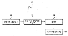
- FIG. 1 is a block diagram of the internal fault diagnosis apparatus of the inlet transformer to which the present invention is applied.
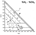
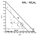
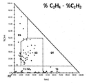
- 2 to 5 are first to fourth X-Y plan views according to the first embodiment of the present invention.
- FIG. 6 is a flowchart showing a process of setting the first to fourth X-Y plan views according to the first embodiment of the present invention.
- FIG. 7 is a flow chart illustrating a method for diagnosing internal defects of an inlet transformer through a gas in oil content ratio according to a first embodiment of the present invention.
- FIG. 8 is a two-dimensional plan view according to a second embodiment of the present invention.
- FIG. 9 is a flowchart illustrating a process of setting a two-dimensional plan view according to a second exemplary embodiment of the present invention.
- FIG. 10 is a flow chart illustrating a method for diagnosing internal defects of an inlet transformer through a gas in oil content ratio according to a second embodiment of the present invention.
- FIG. 1 is a block diagram of an internal fault diagnosis apparatus of an inlet transformer to which the present invention is applied.
- the internal defect diagnosis apparatus 10 of the inflow transformer includes a water gas detection sensor 11, a water gas content ratio calculation unit 12, a database (DB) 13, and a controller 14. It is configured to include).
- the oil in gas detection sensor 11 detects oil in gas contained in the insulating oil in the inlet transformer.
- the oil-in-oil detection sensor 11 is composed of an extraction unit for extracting the oil in gas dissolved in the insulating oil of the inlet transformer and a detection unit for determining the size value of the extracted oil in gas.
- the oil in gas detection sensor 11 extracts hydrogen (H 2), methane (CH 4), acetylene (C 2 H 2), ethylene (C 2 H 4), and ethane (C 2 H 6) from among a plurality of oil gases. .
- CH4 and C2H6 are classified as low temperature defects
- C2H4 is classified as high temperature defects
- H2 is classified as low energy discharge
- C2H2 is classified as high energy discharge.
- the oil-in-oil content ratio calculation unit 12 selects four oil-in-oil gas classified by internal defects among the five oil-in-oil gas detected by the oil-in-oil gas detection sensor 11, and the selected oil-in-oil gas occupies the total content of the oil-in-water gas. Calculate each (%).
- four oil gases of H 2, CH 4, C 2 H 2, and C 2 H 4 are selected among the five oil gases.
- the present invention is not limited to this, and four other oil in gas may be selected.
- the ratio of the selected four oil gases among the total contents of the four selected oil gases is calculated.
- the content ratio of each of the oil in the gas is a value representing the content ratio of each of the oil in gas when the total content of the oil in gas of these four components to 100%. Therefore, each of these oil in gas content ratio is calculated as in Equation 1 below.
- the database 13 stores data that becomes reference information for determining an internal defect of the inflow transformer. More specifically, in the database (DB) 13 in the first embodiment of the present invention, the first XY planar view,% H2 and% C2H2 values, respectively, in which the% H2 and% CH4 values are the X and Y axes, respectively, are X. A second XY planar view made up of the axes and the Y axis, and a third XY planar view made up of the X and Y axes, and the third XY planarity made up of the X and Y axes, respectively; 4 XY floor plans and various data related to these floor plans are stored.
- the defect area is classified according to the type of internal defect.
- these four plan views are for determining the type of internal defects using the values of% H2,% CH4,% C2H2 and% C2H4 detected by the diagnostic inflow transformer 1 to determine the internal defects.
- the four plan views show% H2,% CH4,% C2H2 and% C2H4 for each of the inlet transformers whose types of internal defects are known, and then% H2-% CH4,% H2-% C2H2 and% C2H4-, respectively.
- the database 13 further stores a two-dimensional plan view determined by the values of% H2,% CH4,% C2H4 and% C2H2 and various data related to the two-dimensional plan view. For example, defect areas are classified according to types of internal defects according to% H2,% CH4,% C2H4, and% C2H2 values.
- the two-dimensional plan is used to determine the type of internal defect using the values of% H2,% CH4,% C2H4 and% C2H2 detected by the diagnostic inflow transformer for determining the internal defect.
- the values of% H2,% CH4,% C2H4 and% C2H2 calculated for each inflow transformer of which the type of internal defects are known are four axes forming a two-dimensional plan view of a square shape.
- the two-dimensional plan view allows the areas to be divided according to types of internal defects.
- the control unit 14 calculates the% H2 and% CH4 values, the% H2 and% C2H2 values, the% C2H4 and% C2H2 values, and the% C2H4 and% CH4 values calculated for the diagnostic inflow transformer for determining internal defects.
- the internal defect of the corresponding diagnostic inflow transformer 1 is determined using one or more selected values.
- the controller 14 controls the contents of the oil-in-gas detected by the inflow transformer 1 for diagnosis,% H2-% CH4 value,% H2-% C2H2 value,% C2H4-% C2H2 value, and% C2H4-% CH4 value, respectively.
- the x, y coordinates are used to determine which defect area in each of the first to fourth XY planes stored in the database (DB) 13 corresponds to the defective defects.
- the controller 14 determines the internal defect of the diagnostic inflow transformer using the% H2,% CH4,% C2H4 and% C2H2 values calculated for the diagnostic inflow transformer to determine the internal defect in the second embodiment.
- the control unit 14 has a region corresponding to the content ratio% H2,% CH4,% C2H4 and% C2H2 value of the oil in gas detected by the diagnostic inflow transformer in the two-dimensional floor plan stored in the database (DB) 13 To determine which defect area it corresponds to, finally determine the corresponding internal defect.
- the inflow transformer is known in the internal fault is an inflow transformer in which the failure (internal defect) occurred in the inlet transformer used in the actual site, the content ratio of the oil in the gas corresponding to the internal defect in the internal fault occurs It is used for verification to verify the correlation between each other by matching.
- a diagnostic inflow transformer is an inflow transformer for diagnosing an internal defect using the X-Y plan view.
- 2 to 5 are first to fourth X-Y top views according to the first embodiment of the present invention.
- FIG. 2 to 5 illustrate a plurality of inlet transformers having known types of internal defects according to a first embodiment of the present invention, such as% H2 and% CH4,% H2 and% C2H2,% C2H4 and% C2H2, and% C2H4.
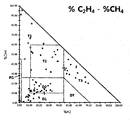
- the internal defects according to the content ratio of the oil in the gas are represented by the first to fourth XY planes, with% CH4 being the X axis and the Y axis, respectively.
- the content ratio of the respective oil-in-oil gas to the contents of the accident is analyzed for a plurality of inflow transformers (known as internal defects) in which internal defects occur during actual operation. .
- % H2 and% CH4 are the X and Y axes, respectively, and the range is set to 0 to 100%, respectively.
- reference numeral A denotes a case where% H2 is 33% and% CH4 is 56% of a specific inlet transformer.
- the first X-Y plan view of FIG. 2 is shown.
- the defect area is determined by dividing the values shown in the first X-Y plan view of FIG. 2 by the type of the internal defect.
- the types of internal defects include partial discharge (PD), low energy discharge (D1), high energy discharge (D2), first thermal defect t ⁇ 300 ° C (T1), and second thermal defect 300 ° C. ⁇ t ⁇ 700 ° C (T2) and the third thermal defect t> 700 ° C (T3).
- FIG. 3 shows% H2 and% C2H2
- FIG. 4 shows% C2H4 and% C2H2
- FIG. 5 shows% C2H4 and% CH4 as X and Y axes, respectively.
- Set to%. 3 to 5 also determine the defect area by classifying the type of internal defect from the values shown in the second to fourth X-Y plan views.
- partial discharge PD, low energy discharge D1, and high energy discharge D2 are determined among thermal defects T and electrical defects E.
- the first and second thermal defects T1 & T2 the third thermal defect T3 of the thermal defect T, the partial discharge PD of the electrical defect E, and the low energy discharge (D1), the high energy discharge (D2), and the common area of thermal defect (T) and electrical defect (E) are determined.
- the first thermal defect T1, the second thermal defect T2, the third thermal defect T3, the partial discharge PD, the low energy discharge D1, and the high energy discharge ( D2) is determined.
- the XY axes of the first to fourth XY plan views have% H2-% CH4 value,% H2-% C2H2 value,% C2H4-% C2H2 value, and% C2H4-% CH4 value, respectively.
- Each defect area is in the range of 0 to 100%, and each defect area is located in a triangular shape formed by connecting straight lines to each other where the XY axis of each XY plane is 100%.
- FIG. 6 is a flowchart illustrating a process of setting the 1-4 X-Y plan view according to the first embodiment of the present invention.
- the oil-in-oil gas contained in the insulating oil is detected for each of a plurality of inflow transformers in which the types of internal defects are known.
- H2, CH4, C2H2 and C2H4 are extracted from the detected oil in gas and the amount thereof is measured (S103).
- the first to fourth X-Y plan views are set using the plurality of% H 2,% CH 4,% C 2 H 4 and% C 2 H 2 values calculated as described above.
- the content ratio% H2 and% CH4 values for each of the inflow transformers of which the types of internal defects are already known are set in advance on the first XY plane by using the first x and y coordinates (S107), A half region of the first XY plane is divided into respective internal defect regions by using the set first x, y coordinates (S109).
- the content ratio% H2 and% C2H2 values which are represented by the types of internal defects, are set in advance on the second XY plane using the second x and y coordinates (S111), respectively, and the plurality of second x, y coordinates are set.
- the half region of the second XY plane is divided into respective internal defect regions (S113).
- the content ratio% C2H4 and% C2H2 values appearing according to the types of internal defects are set in advance on the third XY plane using the third x, y coordinates (S115), and the plurality of set third x, y coordinates are set.
- the half region of the third XY plane is divided into respective internal defect regions by using S117.
- the content ratio% C2H4 and% CH4 values appearing according to the types of internal defects are set in advance on the fourth XY plane using the fourth x, y coordinates (S119), respectively, and the plurality of set fourth x, y coordinates.
- a half region of the fourth XY plane is divided into respective internal defect regions by using S121.
- the first to fourth planar views obtain content ratios of four oil in gas extracted from a plurality of inlet transformers whose internal defects are known in advance, and XY by using two selected content ratio values as x, y coordinates. It is set on the plane to distinguish each defect area. These first to fourth plan views are then used to determine the internal defect of the diagnostic inlet transformer for diagnosing the internal defect.
- FIG. 7 is a flowchart illustrating a method for diagnosing internal defects of an inlet transformer through a gas in oil content ratio according to a first embodiment of the present invention.
- the oil in gas is detected by the inflow transformer 1 for diagnosing the internal defect (S201).
- H2, CH4, C2H2, C2H4 and C2H6 are extracted from the oil-in-oil gas thus detected and the amount thereof is measured (S203).
- Select the four oil gases classified by internal defects among the five oil components extracted calculate the total content of the selected four oil gases, and the content ratio of each oil gas in the calculated total contents (% Calculate That is, in one example of the present invention, the values of% H2,% CH4,% C2H4 and% C2H2 are respectively calculated (S205).
- the present invention is not limited thereto, and four other oil in gas may be selected.
- the internal defect of the corresponding diagnostic inflow transformer 1 is determined by using at least one selected from the calculated values of% H2 and% CH4,% H2 and% C2H2,% C2H4 and% C2H2, and% C2H4 and% CH4. It is determined (S207).
- a region corresponding to the values of% H2 and% CH4 is determined from a defect region divided on the first X-Y plan view, and the internal defect is accurately determined using the determined defect region.
- the regions corresponding to the values of% H2 and% C2H2 are determined in the defect regions divided in the second XY plan view, and the regions corresponding to the values of% C2H4 and% C2H2 are defects divided in the third XY plan view.
- the area is determined in the area, and the area corresponding to the values of% C2H4 and% CH4 is determined in the defect area divided in the fourth XY plan view.
- the internal defect determination using the first to fourth X-Y plan views may be performed in parallel. Therefore, the internal defect may be determined using at least one X-Y plan view selected from the first to fourth X-Y plan views.
- two of the oil content ratios (%) of the four oil-in-oil gases selected from the five oil-in-oil gases generated during internal defects of the inlet transformer are included.
- the combination of gas content ratios should be used to accurately diagnose the internal defects of the inlet transformer.
- FIG. 8 is a two-dimensional plan view according to a second embodiment of the present invention.
- FIG. 8 shows% H2,% CH4,% C2H4 and% C2H2 detected as targets for a plurality of inlet transformers having known types of internal defects according to a second embodiment of the present invention.
- the two-dimensional top view of the formed square shape is shown.
- the ratio of the content of the respective oil-in-oil gas to the contents of the accident is determined for a plurality of inflow transformers (the type of internal defects are already known) in which internal defects occur during actual operation. Analyzed.
- the% H2 value is the upper axis
- the% CH4 value is the right axis
- the% C2H2 value is the left axis
- the% C2H4 value is the lower axis.
- the axes have% H2,% CH4,% C2H4 and% C2H2 values in the range of 0 to 100%, respectively, and thus the two-dimensional plan set in this way has a square shape consisting of four axes.
- the four axes are formed such that the% H2 axis and the% C2H4 axis face each other and the% C2H2 axis and the% CH4 axis face each other.
- one of two selected values of% H2,% CH4,% C2H4 and% C2H2 along the two axes is set to increase and the other one to decrease. That is, at the corners (vertices) of reference A,% CH4 increases and% H2 decreases along each axis.
- each defect area divided in the two-dimensional plan view is located in a rhombus shape formed by connecting in a straight line at the points where the values of% H2,% CH4,% C2H4, and% C2H2 are respectively 50% in four axes.
- reference numeral B denotes a case where% H2 is 30%,% CH4 is 10%,% C2H is 20%, and% C2H2 is 40% of a specific inlet transformer.
- the point of defect diagnosis is the midpoint of a rectangle having four corners, which appears when lines are drawn vertically in the axial direction opposite to each other in the oil-in-gas content ratio value of each axis.
- defect diagnosis points calculated by four oil-in-gas content ratio values calculated by a diagnostic inflow transformer for diagnosing internal defects are included in the defect region of the rhombus shape.
- the types of internal defects include partial discharge (PD), low energy discharge (D1), high energy discharge (D2), first thermal defect t ⁇ 300 ° C (T1), and second thermal defect 300 ° C. ⁇ t ⁇ 700 ° C (T2) and the third thermal defect t> 700 ° C (T3).
- FIG. 9 is a flowchart illustrating a process of setting a two-dimensional X-Y plan view according to a second embodiment of the present invention.
- gas in the oil contained in the insulating oil is detected for each of a plurality of inflow transformers in which the types of internal defects are known.
- H2, CH4, C2H4, C2H2, and C2H6 are extracted from the detected oil in gas and the amount thereof is measured (S303).
- Select four oil gases classified according to internal defects among the five oil components of the extracted five components S305
- the percentage (%) is calculated (S307).
- the values of% H2,% CH4,% C2H4 and% C2H2 are respectively calculated as an example.
- a two-dimensional plan view of a square shape is set using the plurality of% H2,% CH4,% C2H4 and% C2H2 values thus calculated.
- two-dimensional floor plan of square shape is realized by using the values of% H2,% CH4,% C2H4 and% C2H2 as the axes.
- the two-dimensional plan view obtains a content ratio of four oil in gas extracted from a plurality of inlet transformers whose types of internal defects are known in advance, sets the content ratio as a coordinate on the two-dimensional plan view, and then sets the plan view area. It is to distinguish each defect area. This two-dimensional plan is then used to determine the internal defect of the diagnostic inlet transformer for diagnosing the internal defect.
- FIG. 10 is a flowchart illustrating a method for diagnosing internal defects of an inlet transformer through a gas in oil content ratio according to a second embodiment of the present invention.
- the oil in the oil contained in the insulating oil in the inflow transformer for diagnosing the internal defect is detected (S401).
- H2, CH4, C2H4, C2H2 and C2H6 are extracted from the oil-in-oil gas thus detected and the amount thereof is measured (S403).
- the total content of the selected four oil gases is calculated and the total content of the four oil gases is calculated. Calculate the content percentage (%) respectively occupied by the four oil in gas (S407).
- Inflow transformer plays an important role in power supply system as a power equipment that boosts or depresses the supplied voltage. If an internal fault occurs in the inflow transformer, it is important to prevent the accident by detecting it in advance.
- the present invention can accurately diagnose internal defects by collecting and analyzing the gaseous gas contained in the insulating oil in the inlet transformer, so that the present invention can be very useful not only in the inlet transformer manufacturing but also in substations and power companies that apply it in the field. Can be.
Landscapes
- Engineering & Computer Science (AREA)
- Chemical & Material Sciences (AREA)
- Life Sciences & Earth Sciences (AREA)
- Health & Medical Sciences (AREA)
- Power Engineering (AREA)
- General Physics & Mathematics (AREA)
- Physics & Mathematics (AREA)
- Immunology (AREA)
- Food Science & Technology (AREA)
- Medicinal Chemistry (AREA)
- Analytical Chemistry (AREA)
- Biochemistry (AREA)
- General Health & Medical Sciences (AREA)
- Pathology (AREA)
- Oil, Petroleum & Natural Gas (AREA)
- General Chemical & Material Sciences (AREA)
- Chemical Kinetics & Catalysis (AREA)
- Combustion & Propulsion (AREA)
- Housings And Mounting Of Transformers (AREA)
- Testing Electric Properties And Detecting Electric Faults (AREA)
Description


Claims (15)
- 내부결함을 진단하고자 하는 진단용 유입변압기의 절연유에 함유된 유중가스를 분석하여 내부결함을 진단하는 유입변압기의 내부결함 진단방법에 있어서,상기 유중가스 중 H2, CH4, C2H2, C2H4 및 C2H6를 추출하는 제1단계;상기 추출된 5가지 유중가스 중 내부결함별로 구분된 4가지 유중가스를 선택하여 상기 선택된 4가지 유중가스의 전체 함량 중 상기 각각의 유중가스가 차지하는 함량비율(%)을 각각 계산하는 제2단계; 및상기 계산된 %H2와 %CH4, %H2와 %C2H2, %C2H4와 %C2H2, %C2H4와 %CH4, %H2와 %C2H6, %C2H4와 %C2H6의 각 조합들 중 선택된 1개 내지 4개의 조합을 미리 설정된 내구결함 영역에 대응하여 상기 진단용 유입변압기의 내부결함의 종류를 판단하는 제3단계; 를 포함하는 유중가스 함량비 조합을 통한 유입변압기의 내부결함 진단방법.
- 제1항에 있어서, 상기 제3단계는,내부결함의 종류가 알려진 다수의 유입변압기마다 부분방전(PD), 저에너지방전(D1), 고에너지방전(D2), 제1열적결함(t<300℃)(T1), 제2열적결함(300℃<t<700℃)(T2) 및 제3열적결함(t>700℃)(T3)별로 나타나는 비율 %H2 및 %CH4의 값을 각각 x,y 좌표로 하여 제1 X-Y 평면상에 미리 설정하는 단계; 및상기 설정된 다수의 좌표를 이용하여 상기 제1 X-Y 평면의 절반 영역을 부분방전(PD) 결함영역, 저에너지방전(D1) 결함영역, 고에너지방전(D2) 결함영역, 제1열적결함(t<300℃)(T1) 영역, 제2열적결함(300℃<t<700℃)(T2) 영역 및 제3열적결함(t>700℃)(T3) 영역으로 구분하는 단계; 를 포함하고,상기 제2단계에서 계산된 %H2 및 %CH4 값에 대한 x,y 좌표에 대응하는 영역을 이용하여 상기 진단용 유입변압기의 내부결함을 판단하는 것을 특징으로 하는 유중가스 함량비 조합을 통한 유입변압기의 내부결함 진단방법.
- 제1항에 있어서, 상기 제3단계는,내부결함의 종류가 알려진 다수의 유입변압기마다 열적 결함, 전기적 결함 중 부분방전(PD), 저에너지방전(D1), 고에너지방전(D2)별로 나타나는 비율 %H2 및 %C2H2 값을 각각 x,y 좌표로 하여 제2 X-Y 평면상에 설정하는 단계; 및상기 설정된 다수의 좌표를 이용하여 상기 제2 X-Y 평면의 절반 영역을 열적결함 영역, 전기적 결함 중 부분방전(PD) 결함영역, 저에너지방전(D1) 결함영역 및 고에너지방전(D2) 결함영역으로 구분하는 단계; 를 포함하고,상기 제2단계에서 계산된 %H2 및 %C2H2 값에 대한 x,y 좌표에 대응하는 영역을 이용하여 상기 진단용 유입변압기의 내부결함을 판단하는 것을 특징으로 하는 유중가스 함량비 조합을 통한 유입변압기의 내부결함 진단방법.
- 제1항에 있어서, 상기 제3단계는,내부결함의 종류가 알려진 다수의 유입변압기마다 부분방전(PD), 저에너지방전(D1), 고에너지방전(D2), 제1 및 제2열적결함(t<300℃, 300℃<t<700℃)(T1,T2), 제3 열적결함(t>700℃)별로 나타나는 비율 %C2H4 및%C2H2 값을 각각 x,y 좌표로 하여 제3 X-Y 평면상에 설정하는 단계; 및상기 설정된 다수의 좌표를 이용하여 상기 제3 X-Y 평면의 절반 영역을 부분방전(PD) 결함영역, 저에너지방전(D1) 결함영역 및 고에너지방전(D2) 결함영역, 제1 및 제2 열적결함(t<300℃,300℃<t<700℃)(T1,T2) 영역, 제3열적결함(t>700℃)(T3) 영역으로 구분하는 단계; 를 포함하고상기 제2단계에서 계산된 %C2H4 및%C2H2 값에 대한 x,y 좌표에 대응하는 영역을 이용하여 상기 진단용 유입변압기의 내부결함을 판단하는 것을 특징으로 하는 유중가스 함량비 조합을 통한 유입변압기의 내부결함 진단방법.
- 제1항에 있어서, 상기 제3단계는,내부결함의 종류가 알려진 다수의 유입변압기마다 부분방전(PD), 저에너지방전(D1), 고에너지방전(D2), 제1열적결함(t<300℃)(T1), 제2열적결함(300℃<t<700℃)(T2), 제3 열적결함(t>700℃)별로 나타나는 비율 %C2H4 및%CH4 값을 각각 x,y 좌표로 하여 제4 X-Y 평면상에 설정하는 단계; 및상기 설정된 다수의 좌표를 이용하여 상기 제4 X-Y 평면의 절반 영역을 부분방전(PD) 결함영역, 저에너지방전(D1) 결함영역 및 고에너지방전(D2) 결함영역, 제1열적결함(t<300℃)(T1), 제2열적결함(300℃<t<700℃)(T2) 영역, 그리고 제3열적결함(t>700℃)(T3) 영역으로 구분하는 단계; 를 포함하고상기 제2단계에서 계산된 %C2H4 및%CH4 값에 대한 x,y 좌표에 대응하는 영역을 이용하여 상기 진단용 유입변압기의 내부결함을 판단하는 것을 특징으로 하는 유중가스 함량비 조합을 통한 유입변압기의 내부결함 진단방법.
- 제2항 내지 제5항 중 어느 한 항에 있어서,상기 제1 내지 제4 X-Y 평면의 각 X-Y축은 각각 %H2-%CH4 값, %H2-%C2H2 값, %C2H4-%C2H2 값, %C2H4-%CH4 값이 각각 0~100%의 범위를 가지며 상기 결함영역은 상기 X축 및 Y축이 각각 100%인 지점이 서로 직선으로 연결되어 형성된 삼각형 형상 내에 위치하는 것을 특징으로 하는 유중가스 함량비 조합을 통한 유입변압기의 내부결함 진단방법.
- 제6항에 있어서,상기 제2단계에서 계산된 상기 각 유중가스의 함량비율 값은 상기 삼각형 형상의 결함영역 내에 모두 포함되는 것을 특징으로 하는 유중가스 함량비 조합을 통한 유입변압기의 내부결함 진단방법.
- 내부결함의 종류가 알려진 다수의 유입변압기별로 H2, CH4, C2H2, C2H4 및 C2H6의 유중가스를 추출하는 제1단계;상기 다수의 유입변압기별로 추출된 5가지 유중가스 중 내부결함별로 구분된 4가지 유중가스를 선택하여 상기 선택된 4가지 유중가스의 전체 함량 중 상기 각 유중가스가 차지하는 함량비율(%)을 각각 계산하는 제2단계;상기 내부결함별로 나타나는 함량비율 %H2 및 %CH4 값을 각각 제1 x,y 좌표로 하여 제1 X-Y 평면상에 미리 설정하고 상기 다수의 제1 x,y 좌표를 이용하여 상기 제1 X-Y 평면의 절반 영역을 상기 각각의 내부결함 영역으로 구분하는 제3단계;상기 내부결함별로 나타나는 함량비율 %H2 및 %C2H2 값을 각각 제2 x,y 좌표로 하여 제2 X-Y 평면상에 미리 설정하고 상기 다수의 제2 x,y 좌표를 이용하여 상기 제2 X-Y 평면의 절반 영역을 상기 각각의 내부결함 영역으로 구분하는 제4단계;상기 내부결함별로 나타나는 함량비율 %C2H4 및%C2H2 값을 각각 제3 x,y 좌표로 하여 제3 X-Y 평면상에 미리 설정하고 상기 다수의 제3 x,y 좌표를 이용하여 상기 제3 X-Y 평면의 절반 영역을 상기 각각의 내부결함 영역으로 구분하는 제5단계;상기 내부결함별로 나타나는 함량비율 %C2H4 및%CH4 값을 각각 제4 x,y 좌표로 하여 제4 X-Y 평면상에 미리 설정하고 상기 다수의 제4 x,y 좌표를 이용하여 상기 제4 X-Y 평면의 절반 영역을 상기 각각의 내부결함 영역으로 구분하는 제6단계;내부결함을 진단하고자 하는 진단용 유입변압기의 절연유로부터 유중가스 H2, CH4, C2H2 및 C2H4를 추출하고 상기 진단용 유입변압기에서 추출된 4가지 유중가스의 전체함량 중 각 유중가스의 함량비율 %H2, %CH4, %C2H4 및 %C2H2 값을 각각 계산하는 제7단계; 및상기 제7단계에서 계산된 각 유중가스의 함량비율 중 %H2 및 %CH4 값, %H2 및 %C2H2 값, %C2H4 및 %C2H2 값, 그리고 %C2H4 및 %CH4 값들 중 선택된 하나 이상의 값을 이용하여 상기 진단용 유입변압기의 내부결함을 판단하는 제8단계; 를 포함하는 것을 특징으로 하는 유중가스 함량비 조합을 통한 유입변압기의 내부결함 진단방법.
- 내부결함을 진단하고자 하는 진단용 유입변압기의 절연유에 함유된 유중가스를 분석하여 내부결함을 진단하는 유입변압기의 내부결함 진단방법에 있어서,상기 유중가스 중 H2, CH4, C2H4, C2H2 및 C2H6를 추출하는 제1단계;상기 추출된 5가지 유중가스 중 내부결함별로 구분된 4가지 유중가스를 선택하여 상기 선택된 4가지 유중가스의 전체 함량 중 상기 각각의 유중가스가 차지하는 함량비율(%)을 각각 계산하는 제2단계; 및상기 계산된 4가지 유중가스의 함량비율(%) 값과 미리 설정된 상기 4가지 유중가스의 함량비율(%)에 따른 내부결함 영역에 대응하여 상기 진단용 유입변압기의 내부결함을 판단하는 제3단계; 를 포함하는 유중가스 함량비를 통한 유입변압기의 내부결함 진단방법.
- 제9항에 있어서, 상기 제2단계는,내부결함의 종류가 알려진 다수의 유입변압기마다 부분방전(PD), 저에너지방전(D1), 고에너지방전(D2), 제1열적결함(t<300℃)(T1), 제2열적결함(300℃<t<700℃)(T2) 및 제3열적결함(t>700℃)(T3)별로 각각 나타나는 유중가스의 함량비율 %H2, %CH4, %C2H4, %C2H2 값을 2차원 평면상에 미리 설정하는 단계; 및상기 설정된 함량비율 값을 이용하여 상기 2차원 평면을 상기 각각의 결함에 대응하는 6개의 결함영역으로 구분하는 단계; 를 포함하고,상기 제2단계에서 계산된 상기 4개의 함량비율 값에 대응하는 영역을 상기 2차원 평면에 구분된 결함영역에서 결정하고 상기 결정된 결함영역을 이용하여 상기 진단용 유입변압기의 내부결함을 판단하는 유중가스 함량비를 통한 유입변압기의 내부결함 진단방법.
- 제10항에 있어서,상기 2차원 평면은 4개의 축으로 이루어진 정사각형 형상이고 상기 4개의 축은 각각 %H2, %CH4, %C2H4 및 %C2H2 값이 0~100%의 범위를 가지며 상기 구분된 각 결함영역은 상기 4축의 %H2, %CH4, %C2H4 및 %C2H2 값이 각각 50%인 지점에서 직선으로 연결되어 형성된 마름모 형상 내에 위치하는 것으로 하는 유중가스 함량비를 통한 유입변압기의 내부결함 진단방법.
- 제11항에 있어서,상기 4개의 축은 %H2 축과 %C2H4 축이 서로 대향하고 %C2H2 축과 %CH4 축이 서로 대향하도록 형성되는 유중가스 함량비를 통한 유입변압기의 내부결함 진단방법.
- 제11항에 있어서,상기 2차원 평면에서 2개의 축이 이루는 각 모서리로부터 상기 2개의 축을 따라 상기 %H2, %CH4, %C2H4 및 %C2H2 값 중 선택된 2개의 값 중 하나는 증가하고 다른 하나는 감소하는 것으로 하는 유중가스 함량비를 통한 유입변압기의 내부결함 진단방법.
- 제11항에 있어서,상기 제2단계에서 계산된 상기 4개의 함량비율 값은 상기 마름모 형상의 결함영역에 모두 포함되는 것으로 하는 유중가스 함량비를 통한 유입변압기의 내부결함 진단방법.
- 내부결함의 종류가 알려진 다수의 유입변압기별로 H2, CH4, C2H4, C2H2 및 C2H6의 유중가스를 각각 추출하는 제1단계;상기 내부결함의 종류가 알려진 다수의 유입변압기별로 추출된 5가지 유중가스 중 내부결함별로 구분된 4가지 유중가스를 선택하여 상기 선택된 4가지 유중가스의 전체 함량 중 상기 각 유중가스의 함량비율(%)을 각각 계산하는 제2단계;상기 알려진 내부결함의 종류 중에서 부분방전(PD), 저에너지방전(D1), 고에너지방전(D2), 제1열적결함(t<300℃)(T1), 제2열적결함(300℃<t<700℃)(T2), 제3열적결함 (t>700℃)(T3)별로 각각 나타나는 함량비율 %H2, %CH4, %C2H4 및 %C2H2 값을 2차원 평면상에 미리 설정하고 상기 설정된 함량비율 값을 이용하여 상기 2차원 평면을 상기 각각의 결함에 대응하는 결함영역으로 구분하는 제3단계;진단하고자 하는 진단용 유입변압기의 절연유로부터 유중가스를 추출하고 상기 추출된 유중가스의 전체함량 중 설정된 유중가스의 함량비율 %H2, %CH4, %C2H4 및 %C2H2 값을 각각 계산하는 제4단계; 및상기 제4단계에서 계산된 상기 진단용 유입변압기의 각 유중가스의 함량비율 %H2, %CH4, %C2H4 및 %C2H2 값을 상기 2차원 평면의 결함영역에서 결정하고 상기 결정된 결함영역을 이용하여 상기 진단용 유입변압기의 내부결함을 판단하는 제4단계; 를 포함하는 유중가스 함량비를 통한 유입변압기의 내부결함 진단방법.
Priority Applications (1)
| Application Number | Priority Date | Filing Date | Title |
|---|---|---|---|
| US14/368,476 US9535134B2 (en) | 2011-12-26 | 2012-12-26 | Method for diagnosing internal fault of oil-immersed transformer through content ratios of dissolved gases |
Applications Claiming Priority (4)
| Application Number | Priority Date | Filing Date | Title |
|---|---|---|---|
| KR1020110142843A KR101290806B1 (ko) | 2011-12-26 | 2011-12-26 | 유중가스 함량비를 통한 유입변압기의 내부결함 진단방법 |
| KR10-2011-0142841 | 2011-12-26 | ||
| KR10-2011-0142843 | 2011-12-26 | ||
| KR1020110142841A KR101290295B1 (ko) | 2011-12-26 | 2011-12-26 | 유중가스 함량비 조합을 통한 유입변압기의 내부결함 진단방법 |
Publications (1)
| Publication Number | Publication Date |
|---|---|
| WO2013100593A1 true WO2013100593A1 (ko) | 2013-07-04 |
Family
ID=48697945
Family Applications (1)
| Application Number | Title | Priority Date | Filing Date |
|---|---|---|---|
| PCT/KR2012/011506 Ceased WO2013100593A1 (ko) | 2011-12-26 | 2012-12-26 | 유중가스 함량비를 통한 유입변압기의 내부결함 진단방법 |
Country Status (3)
| Country | Link |
|---|---|
| US (1) | US9535134B2 (ko) |
| IN (1) | IN2014CH04904A (ko) |
| WO (1) | WO2013100593A1 (ko) |
Cited By (9)
| Publication number | Priority date | Publication date | Assignee | Title |
|---|---|---|---|---|
| CN103389430A (zh) * | 2013-08-06 | 2013-11-13 | 华北电力大学 | 一种基于贝叶斯判别理论的油浸式变压器故障检测方法 |
| CN103399237A (zh) * | 2013-08-06 | 2013-11-20 | 华北电力大学 | 一种检测油浸式变压器故障的方法 |
| CN103529337A (zh) * | 2013-10-30 | 2014-01-22 | 国家电网公司 | 设备故障与电气量信息间非线性相关关系的识别方法 |
| CN104237413A (zh) * | 2014-09-17 | 2014-12-24 | 吉林省电力科学研究院有限公司 | 基于色谱数据拆分的变压器混合型故障缺陷诊断法 |
| CN104730378A (zh) * | 2015-02-13 | 2015-06-24 | 国家电网公司 | 基于油中溶解气体的变压器内部复合缺陷模糊诊断方法 |
| CN104764869A (zh) * | 2014-12-11 | 2015-07-08 | 国家电网公司 | 一种基于多维特征量的变压器气体故障诊断和报警方法 |
| CN105223293A (zh) * | 2015-11-09 | 2016-01-06 | 江苏省电力公司电力科学研究院 | 基于油色谱在线监测的变压器状态预警方法 |
| CN111695288A (zh) * | 2020-05-06 | 2020-09-22 | 内蒙古电力(集团)有限责任公司电力调度控制分公司 | 一种基于Apriori-BP算法的变压器故障诊断方法 |
| CN119936543A (zh) * | 2025-04-07 | 2025-05-06 | 武汉敢为科技有限公司 | 一种基于油中气体的变压器故障检测方法和相关设备 |
Families Citing this family (8)
| Publication number | Priority date | Publication date | Assignee | Title |
|---|---|---|---|---|
| US9599653B2 (en) * | 2011-12-26 | 2017-03-21 | Hyosung Corporation | Method for diagnosing internal fault of oil-immersed transformer through composition ratio of dissolved gas in oil |
| WO2013100593A1 (ko) * | 2011-12-26 | 2013-07-04 | 주식회사 효성 | 유중가스 함량비를 통한 유입변압기의 내부결함 진단방법 |
| CN105675802A (zh) * | 2014-11-19 | 2016-06-15 | 国网河南省电力公司南阳供电公司 | 一种变压器故障的诊断方法 |
| CN110069793A (zh) * | 2018-01-22 | 2019-07-30 | 中国电力科学研究院有限公司 | 基于可视化模型的变压器故障检测方法 |
| TWI739634B (zh) * | 2020-10-16 | 2021-09-11 | 國立中興大學 | 電力變壓器之故障診斷監控系統 |
| CN114441670B (zh) * | 2021-12-22 | 2024-06-11 | 黄河水利水电开发集团有限公司 | 一种变压器油中溶解气体监测评估方法 |
| PE20251032A1 (es) * | 2022-06-03 | 2025-04-08 | Terramor Inc | Sistemas y metodos para el control de insectos |
| CN116183880B (zh) * | 2023-03-06 | 2025-05-30 | 杭州电子科技大学 | 基于数据聚类检测溶解气体的电力变压器故障检测方法 |
Family Cites Families (3)
| Publication number | Priority date | Publication date | Assignee | Title |
|---|---|---|---|---|
| IT1397472B1 (it) * | 2010-01-14 | 2013-01-16 | Techimp Technologies S A Ora Techimp Technologies S R L | Procedimento diagnostico ed apparato per valutare la condizione di isolamento di un'apparecchiatura elettrica isolata in olio. |
| US9599653B2 (en) * | 2011-12-26 | 2017-03-21 | Hyosung Corporation | Method for diagnosing internal fault of oil-immersed transformer through composition ratio of dissolved gas in oil |
| WO2013100593A1 (ko) * | 2011-12-26 | 2013-07-04 | 주식회사 효성 | 유중가스 함량비를 통한 유입변압기의 내부결함 진단방법 |
-
2012
- 2012-12-26 WO PCT/KR2012/011506 patent/WO2013100593A1/ko not_active Ceased
- 2012-12-26 US US14/368,476 patent/US9535134B2/en active Active
-
2014
- 2014-06-27 IN IN4904CH2014 patent/IN2014CH04904A/en unknown
Non-Patent Citations (5)
| Title |
|---|
| AKBARI A. ET AL.: "A software implementation of the Duval Triangle method", CONFERENCE RECORD OF THE 2008 IEEE INTERNATIONAL SYMPOSIUM ON ELECTRICAL INSULATION. 2008, ISEI 2008, 9 June 2008 (2008-06-09) - 12 June 2008 (2008-06-12), pages 124 - 127, XP031464654 * |
| JIN YEUB, PARK ET AL.: "A study on failure diagnosis examples of Large oil filled transformer using dissolved gas analysis", THE KOREAN INSTITUTE OF ELECTRICAL ENGINEERS, JOURNAL OF 2009 SUMMER CONFERENCE, 14 July 2009 (2009-07-14), pages 740 - 741 * |
| MICHEL DUVAL ET AL.: "Improving the reliability of transformer gas-in-oil diagnosis", ELECTRICAL INSULATION MAGAZINE, vol. 21, no. 4, July 2005 (2005-07-01), pages 21 - 27, XP011265158 * |
| MICHEL DUVAL: "The Duval triangle for load tap changers, non-mineral oils and low temperature faults in transformers", IEEE ELECTRICAL INSULATION MAGAZINE, vol. 24, no. 6, November 2008 (2008-11-01), pages 22 - 29, XP011266847 * |
| SUKHBIR SINGH ET AL.: "Duval Triangle: A Noble Technique for DGA in Power Transformers", INTERNATIONAL JOURNAL OF ELECTRICAL AND POWER ENGINEERING, vol. 4, no. 3, 2010, pages 193 - 197, XP055074765 * |
Cited By (13)
| Publication number | Priority date | Publication date | Assignee | Title |
|---|---|---|---|---|
| CN103399237A (zh) * | 2013-08-06 | 2013-11-20 | 华北电力大学 | 一种检测油浸式变压器故障的方法 |
| CN103389430A (zh) * | 2013-08-06 | 2013-11-13 | 华北电力大学 | 一种基于贝叶斯判别理论的油浸式变压器故障检测方法 |
| CN103399237B (zh) * | 2013-08-06 | 2016-01-13 | 华北电力大学 | 一种检测油浸式变压器故障的方法 |
| CN103529337A (zh) * | 2013-10-30 | 2014-01-22 | 国家电网公司 | 设备故障与电气量信息间非线性相关关系的识别方法 |
| CN104237413A (zh) * | 2014-09-17 | 2014-12-24 | 吉林省电力科学研究院有限公司 | 基于色谱数据拆分的变压器混合型故障缺陷诊断法 |
| CN104764869A (zh) * | 2014-12-11 | 2015-07-08 | 国家电网公司 | 一种基于多维特征量的变压器气体故障诊断和报警方法 |
| WO2016127598A1 (zh) * | 2015-02-13 | 2016-08-18 | 国家电网公司 | 基于油中溶解气体的变压器内部复合缺陷模糊诊断方法 |
| CN104730378A (zh) * | 2015-02-13 | 2015-06-24 | 国家电网公司 | 基于油中溶解气体的变压器内部复合缺陷模糊诊断方法 |
| CN105223293A (zh) * | 2015-11-09 | 2016-01-06 | 江苏省电力公司电力科学研究院 | 基于油色谱在线监测的变压器状态预警方法 |
| CN111695288A (zh) * | 2020-05-06 | 2020-09-22 | 内蒙古电力(集团)有限责任公司电力调度控制分公司 | 一种基于Apriori-BP算法的变压器故障诊断方法 |
| CN111695288B (zh) * | 2020-05-06 | 2023-08-08 | 内蒙古电力(集团)有限责任公司电力调度控制分公司 | 一种基于Apriori-BP算法的变压器故障诊断方法 |
| CN119936543A (zh) * | 2025-04-07 | 2025-05-06 | 武汉敢为科技有限公司 | 一种基于油中气体的变压器故障检测方法和相关设备 |
| CN119936543B (zh) * | 2025-04-07 | 2025-06-17 | 武汉敢为科技有限公司 | 一种基于油中气体的变压器故障检测方法和相关设备 |
Also Published As
| Publication number | Publication date |
|---|---|
| US9535134B2 (en) | 2017-01-03 |
| US20150007635A1 (en) | 2015-01-08 |
| IN2014CH04904A (ko) | 2016-02-05 |
Similar Documents
| Publication | Publication Date | Title |
|---|---|---|
| WO2013100593A1 (ko) | 유중가스 함량비를 통한 유입변압기의 내부결함 진단방법 | |
| WO2013100591A1 (ko) | 유중가스 조성비를 통한 유입변압기의 내부결함 진단방법 | |
| KR101290807B1 (ko) | 유중가스 조성비를 통한 유입변압기의 내부 결함 진단방법 | |
| De Santis et al. | Analysis of the origin of measured voltage sags in interconnected networks | |
| EP0681187A2 (en) | Instrument and method for testing local area network cables | |
| KR101290295B1 (ko) | 유중가스 함량비 조합을 통한 유입변압기의 내부결함 진단방법 | |
| CN106597158A (zh) | 配电变压器综合检测装置 | |
| WO2021145636A1 (ko) | 변전소의 자산 관리 방법 | |
| CN113283041B (zh) | 基于多源信息融合感知算法的停电区域快速研判方法 | |
| KR101325177B1 (ko) | 유중가스 조성비를 통한 유입변압기의 내부결함 진단방법 | |
| CN105606969B (zh) | 一种能够分级别预警的输电变压器控制系统 | |
| WO2017116091A1 (ko) | 유입 변압기 진단 방법 | |
| CN109188197A (zh) | 一种用于高压电缆健康指数的评估系统及方法 | |
| CN110568275A (zh) | 一种基于配电网公专变数据的缺相故障研判方法及系统 | |
| CN109239495A (zh) | 一种变压器性能自动检测装置 | |
| KR20130074673A (ko) | 유중가스 함량비를 통한 유입변압기의 내부결함 진단방법 | |
| WO2022080740A1 (ko) | Gis 기반 스파샬 웨이퍼 맵 생성 방법, 이를 이용한 웨이퍼 테스트 결과 제공 방법 | |
| CN115541962A (zh) | 一种全自动电容电流监测装置 | |
| Kaur et al. | A New Six-Gas-Based Fault Prediction Graphical Technique in Dissolved Gas Analysis for Oil-Immersed Power Transformer | |
| CN120334687A (zh) | 一种基于组合式高频电流传感器的电缆局放干扰识别方法 | |
| Kim et al. | Advanced dissolved gas analysis method with stray gassing diagnosis | |
| CN209296825U (zh) | 一种变压器性能自动检测装置 | |
| CN107843788A (zh) | 一种利用特征气体进行油浸变压器的故障诊断方法 | |
| CN113009293A (zh) | 应用油中特征气体参量辨识混合绝缘油变压器故障的方法 | |
| CN115684829A (zh) | 一种电力二次回路故障检测预警方法及系统 |
Legal Events
| Date | Code | Title | Description |
|---|---|---|---|
| 121 | Ep: the epo has been informed by wipo that ep was designated in this application |
Ref document number: 12861782 Country of ref document: EP Kind code of ref document: A1 |
|
| WWE | Wipo information: entry into national phase |
Ref document number: 14368476 Country of ref document: US |
|
| NENP | Non-entry into the national phase |
Ref country code: DE |
|
| WWE | Wipo information: entry into national phase |
Ref document number: DZP2014000424 Country of ref document: DZ |
|
| 122 | Ep: pct application non-entry in european phase |
Ref document number: 12861782 Country of ref document: EP Kind code of ref document: A1 |