US9535134B2 - Method for diagnosing internal fault of oil-immersed transformer through content ratios of dissolved gases - Google Patents
Method for diagnosing internal fault of oil-immersed transformer through content ratios of dissolved gases Download PDFInfo
- Publication number
- US9535134B2 US9535134B2 US14/368,476 US201214368476A US9535134B2 US 9535134 B2 US9535134 B2 US 9535134B2 US 201214368476 A US201214368476 A US 201214368476A US 9535134 B2 US9535134 B2 US 9535134B2
- Authority
- US
- United States
- Prior art keywords
- fault
- region
- oil
- dissolved gases
- values
- Prior art date
- Legal status (The legal status is an assumption and is not a legal conclusion. Google has not performed a legal analysis and makes no representation as to the accuracy of the status listed.)
- Active, expires
Links
- 239000007789 gas Substances 0.000 title claims abstract description 189
- 238000000034 method Methods 0.000 title claims abstract description 58
- HSFWRNGVRCDJHI-UHFFFAOYSA-N Acetylene Chemical compound C#C HSFWRNGVRCDJHI-UHFFFAOYSA-N 0.000 claims abstract description 228
- 125000000219 ethylidene group Chemical group [H]C(=[*])C([H])([H])[H] 0.000 claims abstract description 99
- 238000003745 diagnosis Methods 0.000 claims abstract description 56
- OTMSDBZUPAUEDD-UHFFFAOYSA-N Ethane Chemical compound CC OTMSDBZUPAUEDD-UHFFFAOYSA-N 0.000 claims description 20
- 229910003460 diamond Inorganic materials 0.000 claims description 6
- 239000010432 diamond Substances 0.000 claims description 6
- 239000000203 mixture Substances 0.000 claims description 6
- 230000007423 decrease Effects 0.000 claims description 4
- 238000009413 insulation Methods 0.000 claims description 4
- VNWKTOKETHGBQD-UHFFFAOYSA-N methane Chemical compound C VNWKTOKETHGBQD-UHFFFAOYSA-N 0.000 description 88
- UFHFLCQGNIYNRP-UHFFFAOYSA-N Hydrogen Chemical compound [H][H] UFHFLCQGNIYNRP-UHFFFAOYSA-N 0.000 description 3
- 238000004458 analytical method Methods 0.000 description 3
- 239000001257 hydrogen Substances 0.000 description 3
- 229910052739 hydrogen Inorganic materials 0.000 description 3
- -1 hydrogen H2 Chemical class 0.000 description 3
- 239000005977 Ethylene Substances 0.000 description 2
- 230000002159 abnormal effect Effects 0.000 description 2
- 238000010586 diagram Methods 0.000 description 2
- 238000005516 engineering process Methods 0.000 description 2
- 238000012986 modification Methods 0.000 description 2
- 230000004048 modification Effects 0.000 description 2
- 230000015556 catabolic process Effects 0.000 description 1
- 238000006243 chemical reaction Methods 0.000 description 1
- 150000001875 compounds Chemical class 0.000 description 1
- 238000007796 conventional method Methods 0.000 description 1
- 230000003247 decreasing effect Effects 0.000 description 1
- 230000006866 deterioration Effects 0.000 description 1
- 238000011161 development Methods 0.000 description 1
- 230000000694 effects Effects 0.000 description 1
- 239000000284 extract Substances 0.000 description 1
- 229910052500 inorganic mineral Inorganic materials 0.000 description 1
- 239000011810 insulating material Substances 0.000 description 1
- 238000004519 manufacturing process Methods 0.000 description 1
- 239000011707 mineral Substances 0.000 description 1
- 238000013021 overheating Methods 0.000 description 1
Images


Classifications
-
- G—PHYSICS
- G01—MEASURING; TESTING
- G01R—MEASURING ELECTRIC VARIABLES; MEASURING MAGNETIC VARIABLES
- G01R31/00—Arrangements for testing electric properties; Arrangements for locating electric faults; Arrangements for electrical testing characterised by what is being tested not provided for elsewhere
- G01R31/40—Testing power supplies
-
- G—PHYSICS
- G01—MEASURING; TESTING
- G01N—INVESTIGATING OR ANALYSING MATERIALS BY DETERMINING THEIR CHEMICAL OR PHYSICAL PROPERTIES
- G01N33/00—Investigating or analysing materials by specific methods not covered by groups G01N1/00 - G01N31/00
- G01N33/0004—Gaseous mixtures, e.g. polluted air
-
- G—PHYSICS
- G01—MEASURING; TESTING
- G01N—INVESTIGATING OR ANALYSING MATERIALS BY DETERMINING THEIR CHEMICAL OR PHYSICAL PROPERTIES
- G01N33/00—Investigating or analysing materials by specific methods not covered by groups G01N1/00 - G01N31/00
- G01N33/26—Oils; Viscous liquids; Paints; Inks
-
- G—PHYSICS
- G01—MEASURING; TESTING
- G01N—INVESTIGATING OR ANALYSING MATERIALS BY DETERMINING THEIR CHEMICAL OR PHYSICAL PROPERTIES
- G01N33/00—Investigating or analysing materials by specific methods not covered by groups G01N1/00 - G01N31/00
- G01N33/26—Oils; Viscous liquids; Paints; Inks
- G01N33/28—Oils, i.e. hydrocarbon liquids
- G01N33/2835—Specific substances contained in the oils or fuels
- G01N33/2841—Gas in oils, e.g. hydrogen in insulating oils
-
- H—ELECTRICITY
- H01—ELECTRIC ELEMENTS
- H01F—MAGNETS; INDUCTANCES; TRANSFORMERS; SELECTION OF MATERIALS FOR THEIR MAGNETIC PROPERTIES
- H01F27/00—Details of transformers or inductances, in general
- H01F27/08—Cooling; Ventilating
- H01F27/10—Liquid cooling
- H01F27/12—Oil cooling
-
- H—ELECTRICITY
- H01—ELECTRIC ELEMENTS
- H01F—MAGNETS; INDUCTANCES; TRANSFORMERS; SELECTION OF MATERIALS FOR THEIR MAGNETIC PROPERTIES
- H01F27/00—Details of transformers or inductances, in general
- H01F27/40—Structural association with built-in electric component, e.g. fuse
- H01F27/402—Association of measuring or protective means
-
- G—PHYSICS
- G01—MEASURING; TESTING
- G01F—MEASURING VOLUME, VOLUME FLOW, MASS FLOW OR LIQUID LEVEL; METERING BY VOLUME
- G01F1/00—Measuring the volume flow or mass flow of fluid or fluent solid material wherein the fluid passes through a meter in a continuous flow
- G01F1/68—Measuring the volume flow or mass flow of fluid or fluent solid material wherein the fluid passes through a meter in a continuous flow by using thermal effects
- G01F1/696—Circuits therefor, e.g. constant-current flow meters
- G01F1/698—Feedback or rebalancing circuits, e.g. self heated constant temperature flowmeters
-
- G—PHYSICS
- G01—MEASURING; TESTING
- G01F—MEASURING VOLUME, VOLUME FLOW, MASS FLOW OR LIQUID LEVEL; METERING BY VOLUME
- G01F1/00—Measuring the volume flow or mass flow of fluid or fluent solid material wherein the fluid passes through a meter in a continuous flow
- G01F1/72—Devices for measuring pulsing fluid flows
-
- G01F25/0007—
-
- G01F25/0015—
-
- G01F25/0053—
-
- G—PHYSICS
- G01—MEASURING; TESTING
- G01F—MEASURING VOLUME, VOLUME FLOW, MASS FLOW OR LIQUID LEVEL; METERING BY VOLUME
- G01F25/00—Testing or calibration of apparatus for measuring volume, volume flow or liquid level or for metering by volume
- G01F25/10—Testing or calibration of apparatus for measuring volume, volume flow or liquid level or for metering by volume of flowmeters
-
- G—PHYSICS
- G01—MEASURING; TESTING
- G01F—MEASURING VOLUME, VOLUME FLOW, MASS FLOW OR LIQUID LEVEL; METERING BY VOLUME
- G01F25/00—Testing or calibration of apparatus for measuring volume, volume flow or liquid level or for metering by volume
- G01F25/10—Testing or calibration of apparatus for measuring volume, volume flow or liquid level or for metering by volume of flowmeters
- G01F25/11—Testing or calibration of apparatus for measuring volume, volume flow or liquid level or for metering by volume of flowmeters using a seal ball or piston in a test loop
-
- G—PHYSICS
- G01—MEASURING; TESTING
- G01F—MEASURING VOLUME, VOLUME FLOW, MASS FLOW OR LIQUID LEVEL; METERING BY VOLUME
- G01F25/00—Testing or calibration of apparatus for measuring volume, volume flow or liquid level or for metering by volume
- G01F25/10—Testing or calibration of apparatus for measuring volume, volume flow or liquid level or for metering by volume of flowmeters
- G01F25/15—Testing or calibration of apparatus for measuring volume, volume flow or liquid level or for metering by volume of flowmeters specially adapted for gas meters
-
- G01R31/027—
-
- G—PHYSICS
- G01—MEASURING; TESTING
- G01R—MEASURING ELECTRIC VARIABLES; MEASURING MAGNETIC VARIABLES
- G01R31/00—Arrangements for testing electric properties; Arrangements for locating electric faults; Arrangements for electrical testing characterised by what is being tested not provided for elsewhere
- G01R31/50—Testing of electric apparatus, lines, cables or components for short-circuits, continuity, leakage current or incorrect line connections
- G01R31/62—Testing of transformers
Definitions
- the present invention relates to a method of diagnosing an internal fault of an oil-immersed transformer, and more particularly, to a method of accurately diagnosing an internal fault of an oil-immersed transformer by analyzing a content ratio of dissolved gases generated when the internal fault occurs in the oil-immersed transformer.
- An oil-immersed transformer installed in a transformer substation or an electric power plant is one of the more important components of an electric power supplying system, and it is required to have high reliability.
- the oil-immersed transformer may have its electrical and mechanical performance degraded due to deterioration during operation, which causes an abnormal condition of the oil-immersed transformer. This phenomenon may cause a serious accident if it may not be detected in advance and appropriately treated.
- the types of the internal faults in the oil-immersed transformer and the method of diagnosing the internal fault of the oil-immersed transformer through the dissolved gases are prescribed in the international standard (IEC 60599: Mineral oil-impregnated electrical equipment in service guide to the interpretation of dissolved and free gases analysis and IEEE C57.104: IEEE Guide for the interpretation of gases in oil-immersed transformer), and most of the electric power companies and users of oil-immersed electric power devices estimate the internal fault depending on the international standard.
- the types of faults described in these international standards are classified into an electrical fault and a thermal fault, and more specifically into six faults including partial discharges, discharges of low energy D1, discharges of high energy D2, a first thermal fault (t ⁇ 300° C.) T1, a second thermal fault (300° C. ⁇ t ⁇ 700° C.) T2, and a third thermal fault (t>700° C.) T3.
- the gases that are subject to analysis in the international standards include five compounds such as hydrogen H2, methane CH4, ethane C2H2, ethylene C2H4, and acetylene C2H2.
- the classification of faults is determined by analyzing a composition ratio of the five gases, a content ratio of each of the five gases, a range of a key gas, and the like.
- problems as follows:
- the diagnosis method using the key gas since the fault is diagnosed by using only the key gas (a maximum gas value), a pattern, a composition, and a variation according to energy in each fault cannot be applied to the diagnosis method, resulting in an increase in a ratio of wrong diagnosis. For example, if not the key gas but another gas has the maximum value, there is a problem in that a region is present in which the diagnosis is impossible.
- An aspect of the present invention is to provide a method of diagnosing an internal fault of a corresponding oil-immersed transformer through a combination of a content ratio of dissolved gases.
- another aspect of the present invention is to provide a method of diagnosing an internal fault of an oil-immersed transformer through a content ratio of dissolved gases.
- a method of diagnosing an internal fault of an oil-immersed transformer through a combination of content ratios of dissolved gases which is capable of analyzing the dissolved gases contained in the insulation oil of the oil-immersed transformer of which the internal fault is able to be diagnosed.
- the method includes: a first step of extracting H2, CH4, C2H2, C2H4, and C2H6 from the dissolved gases; a second step of selecting four dissolved gases, classified depending on each internal fault, from the five extracted and dissolved gases, so as to calculate a content ratio of each dissolved gas to a total content of the four selected and dissolved gases; and a third step of determining a type of the internal fault of the immersed transformer for the diagnosis by enabling one to four combinations, which are selected from combinations of % H2 and % CH4, % H2 and % C2H2, % C2H4 and % C2H2, % C2H4 and % CH4, % H2 and % C2H6, and % C2H4 and % C2H6 which are calculated, to correspond to a predetermined internal fault region.
- the third step includes: setting values of the content ratio of % H2 and % CH4 of each oil-immersed transformer, of which a type of the internal faults is known, depending on each of a partial discharge PD, a low energy discharge D1, a high energy discharge D2, a first thermal fault (t ⁇ 300° C.) T1, a second thermal fault (300° C. ⁇ t ⁇ 700° C.), and a third thermal fault (t>700° C.) T3; and classifying half a region of the first xy-plane into a partial discharge (PD) fault region, a low energy discharge (D1) fault region, a high energy discharge (D2) fault region, a first thermal fault (t ⁇ 300° C.) (T1) region, a second thermal fault (300° C. ⁇ t ⁇ 700° C.) (T2) region, and a thermal fault (t>700° C.) region by using the plurality of set coordinates, wherein the internal fault of the oil-immersed transformer for the diagnosis is
- the third step includes: setting of the values of % H2 and % C2H2, which are content ratios indicated depending on each of a partial discharge (PD), a low energy discharge (D1), and a high energy discharge (D2) of a thermal fault and an electrical fault, as x and y coordinates for each of a plurality of oil-immersed transformers, of which a type of the internal fault is known, on a second xy-plane; and classifying half a region of the second xy-plane into the partial discharge (PD) fault region, a low energy discharge (D1) fault region, and a high energy discharge (D2) fault region of a thermal fault region and an electrical region, wherein the internal fault of the oil-immersed transformer used for diagnosis is determined by using a region corresponding to x and y coordinates for the values of % H2 and % C2H2 calculated in the second step.
- % H2 and % C2H2 are content ratios indicated depending on each of a partial discharge (PD),
- the third step includes: setting values of the content ratio of % C2H4 and % C2H2 of each oil-immersed transformer, of which a type of the internal fault is known, depending on each of a partial discharge PD, a low energy discharge D1, a high energy discharge D2, a first thermal fault (t ⁇ 300° C.) T1, a second thermal fault (300° C. ⁇ t ⁇ 700° C.) T2, and a third thermal fault (t>700° C.) T3, as x and y coordinates on a third xy-plane; and classifying half a region of the first xy-plane into a partial discharge (PD) fault region, a low energy discharge (D1) fault region, a high energy discharge (D2) fault region, a first thermal fault (t ⁇ 300° C.) (T1) region, a second thermal fault (300° C. ⁇ t ⁇ 700° C.) (T2) region, and a thermal fault (t>700° C.) region by using the
- the third step includes: setting values of the content ratio of % C2H4 and % CH4 of each oil-immersed transformer, of which a type of the internal faults is known, depending on each of a partial discharge PD, a low energy discharge D1, a high energy discharge D2, a first thermal fault (t ⁇ 300° C.) T1, a second thermal fault (300° C. ⁇ t ⁇ 700° C.) T2, and a third thermal fault (t>700° C.) T3, as x and y coordinates on a four X-Y plane; and classifying half a region of the fourth xy-plane into a partial discharge (PD) fault region, a low energy discharge (D1) fault region, a high energy discharge (D2) fault region, a first thermal fault (t ⁇ 300° C.) (T1) region, a second thermal fault (300° C. ⁇ t ⁇ 700° C.) (T2) region, and a thermal fault (t>700° C.) (T3) region by using
- the values of % H2-% CH4, % H2-% C2H2, % C2H4-% C2H2, and % C2H4-% CH4 are in a range of 0 ⁇ 100% on each x-y axis on the first to fourth xy-plane, and the fault region is located within a triangular shape defined by connecting points, at which the x axis and the y axis are 100%.
- the content ratio of each dissolved gas, which is calculated in the second step, is included in the fault region within the triangular shape.
- a method of diagnosing an internal fault of an oil-immersed transformer through a combination of content ratios of dissolved gases includes: a first step of extracting the dissolved gases of H2, CH4, C2H2, C2H4, and C2H6 from each oil-immersed transformer of which a type of the internal faults is known; a second step of selecting four dissolved gases, classified depending on each internal fault, from the five extracted and dissolved gases, so as to calculate a content ratio of each dissolved gas to a total content of the four selected and dissolved gases; a third step of classifying half a region of the first xy-plane into the internal fault region by using the plurality of the first x and y coordinates after setting the values of % H2 and % CH4, which are content ratios indicated by each internal fault, as the first x and y coordinates respectively on the first xy-plane; a fourth step of classifying half a region of the second xy-
- a method of diagnosing an internal fault of an oil-immersed transformer through content ratios of dissolved gases which is capable of analyzing dissolved gases contained in insulation oil of the oil-immersed transformer of which the internal fault is able to be diagnosed.
- the method includes: a first step of extracting H2, CH4, C2H4, C2H2, and C2H6 from the dissolved gases; a second step of selecting four dissolved gases, classified depending on each internal fault, from the five extracted and dissolved gases, so as to calculate a content ratio of each dissolved gas to a total content of the four selected dissolved gases; and, a third step of determining the internal fault of the oil-immersed gases for the diagnosis in correspondence to the content ratios of the four dissolved gases which are calculated and an internal fault region according to the content ratios of the four dissolved gases which are predetermined.
- the second step includes: setting values of the content ratio of % H2, % CH4, % C2H4, and % C2H2 of the dissolved gases of each oil-immersed transformer, of which a type of the internal faults is known, indicated depending on each of a partial discharge PD, a low energy discharge D1, a high energy discharge D2, a first thermal fault (t ⁇ 300° C.) T1, a second thermal fault (300° C. ⁇ t ⁇ 700° C.), and a third thermal fault (t>700° C.) T3 on a two-dimensional plane in advance; and classifying the two-dimensional plane into six fault regions corresponding to each fault by using the set content ratios, wherein a region corresponding to the four content ratios calculated in the second step is determined in the fault regions divided on the two-dimensional plane, and the internal fault of the oil-immersed transformer for the diagnosis is determined by using the determined fault region.
- the two-dimensional plane has a square shape defined by four axes, the values of % H2, % CH4, % C2H4, and % C2H2 are in a range of 0 ⁇ 100% on the four axes respectively, and each of the divided fault regions is located within a diamond shape formed by connecting points, at which the values of % H2, % CH4, % C2H4, and % C2H2 of the four axes are 50% respectively, by straight lines.
- the % H2 axis and % C2H4 axis are opposite to each other, and the % C2H2 axis and the % CH4 axis are opposite to each other.
- one of two values selected from the values of % H2, % CH4, % C2H4, and % C2H2 increases along two axes from each corner defined by the two axes, and the other one decreases.
- the four content ratios calculated in the second step are included in the fault region having the diamond shape.
- a method of diagnosing an internal fault of an oil-immersed transformer through a composition ratio of dissolved gas includes: a first step of extracting the dissolved gases of H2, CH4, C2H2, C2H4, and C2H6 from each oil-immersed transformer of which a type of the internal fault is known; a second step of selecting four dissolved gases, classified depending on each internal fault, from the five dissolved gases which are extracted from each of a plurality of oil-immersed transformers of which a type of the internal fault is known, so as to calculate a content ratio of each dissolved gas to a total content of the four selected dissolved gases; a third step of setting values of the content ratios of % H2, % CH4, % C2H4, and % C2H2 of the dissolved gases of each oil-immersed transformer, of which a type of the internal faults is known, indicated depending on each of a partial discharge PD, a low energy discharge D1, a
- the ratio of a wrong diagnosis of the internal fault in the oil-immersed transformer can be reduced.
- the reliability of the diagnosis of the internal fault can be improved.
- FIG. 1 is a block diagram illustrating a configuration of an apparatus for diagnosing an internal fault of an oil-immersed transformer to which the present application is applied.
- FIGS. 2 to 5 are first to fourth X-Y plane views according to a first embodiment of the present invention.
- FIG. 6 is a flowchart illustrating a process of constructing the first to fourth X-Y plane views according to the first embodiment of the present invention.
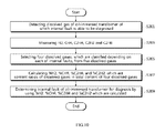
- FIG. 7 is a flowchart illustrating a process of diagnosing the internal fault of an oil-immersed transformer through a content ratio of dissolved gases according to the first embodiment of the present invention.
- FIG. 8 is a two-dimensional plane view according to a second embodiment of the present invention.
- FIG. 9 is a flowchart illustrating a process of constructing a two-dimensional plane view according to the second embodiment.
- FIG. 10 is a flowchart illustrating a process of diagnosing the internal fault of an oil-immersed transformer through a content ratio of dissolved gases according to the second embodiment of the present invention.
- FIG. 1 is a block diagram illustrating a configuration of an apparatus for diagnosing an internal fault of an oil-immersed transformer to which the present application is applied.
- the apparatus of diagnosing the internal fault of the oil-immersed transformer 10 includes a sensor 11 for detecting dissolved gases, a calculator 12 for calculating content ratios of the dissolved gases, a database (DB) 13 , and a controller 14 .
- the sensor 11 for detecting the dissolved gases detects the dissolved gases contained in insulating oil in the oil-immersed transformer.
- the sensor 11 for detecting the dissolved gases includes an extractor for extracting the dissolved gases from the insulating oil of the oil-immersed transformer, and a detector for determining a magnitude of the dissolved gases extracted from the insulating oil.
- the sensor 11 for detecting the dissolved gas extracts hydrogen H2, methane CH4, acetylene C2H2, ethylene C2H4, and ethane C2H6 from the plurality of dissolved gases, and measures quantity of each gas.
- CH4 and C2H6 are classified as a low temperature fault
- C2H4 is classified as a high temperature fault
- H2 is classified as a low energy discharge
- C2H2 is classified as a high energy discharge.
- the calculator 12 for calculating content ratios of the dissolved gases selects four dissolved gases, which are classified according to each of the internal faults, from the five dissolved gases detected by the dissolved gas detecting sensor 11 , and calculates a content ratio (%) of each of the four dissolved gases selected and dissolved gases in a total content.
- a content ratio (%) of each of the four dissolved gases selected and dissolved gases in a total content will be described for convenience of description.
- the present invention is not limited thereto, and another grouping of four dissolved gases may be selected.
- content ratios of each of the four selected and dissolved gases among the total content of the four selected and dissolved gases i.e., values of % H2, % CH4, % C2H2, and % C2H4, are calculated.
- the content ratios of each of the dissolved gases are indicated by percentage when the total content of the dissolved gases consisting of four components is defined as 100%. Accordingly, the content ratio of each of the dissolved gases is calculated by Equation 1 below.
- the database (DB) 13 stores data, which is reference information for determining the internal fault of the immersed transformer. Particularly, in the first embodiment of the present invention, the database DB 13 stores a first xy plane view, including an x-axis and a y-axis on which % H2 and % CH4 are indicated; a second xy plane view, including an x-axis and a y-axis on which % H2 and % C2H2 are indicated; a third xy-plane view, including an x-axis and a y-axis on which % C2H4 and % CH4 are indicated; a fourth xy-plane view, including an x-axis and a y-axis on which % C2H4 and % C2H2 are indicated; and various data related to these plane views.
- a first xy plane view including an x-axis and a y-axis on which % H2 and % CH4 are indicated
- a fault region is classified according to a type of the internal fault.
- the four plane views is used to determine the type of the internal fault by using the values of % H2, % CH4, % C2H4, and % C2H4 detected from the oil-immersed transformer 10 , of which the internal fault is able to be determined.
- values of % H2-% CH4, values of % H2-% C2H2, values of % C2H4-% C2H2, and values of % C2H4-% CH4 are preset as x and y coordinates on the first to fourth xy-planes, and a region corresponding to each of the types of the internal faults is distinguished by using each of the x and y coordinates.
- the database 13 stores a two-dimensional plane view determined by values of % H2, % CH4, % C2H4, % C2H2, and various other data related to the two-dimensional plane view.
- a fault region is distinguished depending on each of the types of the internal faults according to the values of % H2, % CH4, % C2H4, and % C2H2.
- the two-dimensional plane view is used to determine the type of the internal fault by using the values of % H2, % CH4, % C2H4, and % C2H2 detected from the oil-immersed transformer of which the internal fault is able to be determined.
- the values of % H2, % CH4, % C2H4 and % C2H2, which are calculated for each of the plural oil-immersed transformer of which the type of the internal fault is known, become four axes, which form the two-dimensional plane view having a square shape. Further, in the two-dimensional plane view, a region is distinguished to correspond to each of the types of the internal faults.
- the controller 14 determines the internal fault of the corresponding oil-immersed transformer 10 for the diagnosis by using one or more values selected from the value of % H2 and % CH4, the value of % H2 and % C2H2, the value of % C2H4 and % C2H2, and the value of % C2H4 and % CH4 which are calculated for the oil-immersed transformer for the diagnosis, of which the internal fault is able to be determined, in the first embodiment.
- the controller 14 defines the value of % H2-% CH4, the value of % H2-% C2H2, the value of % C2H4-% C2H2, and the value of % C2H4-% CH4, which are the contents of the dissolved gases detected from the oil-immersed transformer 10 for the diagnosis, as the x and y coordinate respectively. It then, determines the fault region in the first to fourth xy-planes stored in the database (DB) 13 , to which each x and y coordinate corresponds. Finally, the controller 14 determines the corresponding internal fault.
- DB database
- the controller 14 determines the internal fault of the oil-immersed transformer for the diagnosis by using the values of % H2, % CH4, % C2H4 and % C2H2 calculated for the oil-immersed transformer for the diagnosis, of which the internal fault is determined in the second embodiment. Particularly, the controller 14 determines a fault region in the two-dimensional plane view stored in the database (DB) 13 to which the values of the content ratios of % H2, % CH4, % C2H4, and % C2H2 of the dissolved gases detected in the oil-immersed transformer for the diagnosis correspond. It then, finally determines the corresponding internal fault.
- DB database
- the oil-immersed transformer of which the internal fault is known refers to the oil-immersed transformer, which has a failure (internal fault), among the oil-immersed transformers used in a field, and it is used for inspecting a correlation between the content ratio by matching the content ratios of the dissolved gases corresponding to the internal fault in the state that the internal fault occurs.
- the oil-immersed transformer for the diagnosis refers to an oil-immersed transformer of which an internal fault is diagnosed by using the xy-plane view.
- FIGS. 2 to 5 are the first to fourth plane views according to the first embodiment of the present invention.
- FIGS. 2 to 5 show the first to fourth xy-plane views on which the internal faults according to the content ratios of the corresponding dissolved gases are indicated by defining each of % H2 and % CH4, % H2 and % C2H2, % C2H4 and % C2H2, and % C2H4 and % CH4 as an X axis and a Y axis, respectively, with relation to a plurality of oil-immersed transformers of which the type of the internal fault is already known according to the first embodiment of the present invention.
- the content ratio of each dissolved gas during a failure (the type of the internal fault) is analyzed with respect to the plurality of oil-immersed transformers of which the internal faults occur in an operation of the oil-immersed transformers in a field.
- % H2 and % CH4 are defined as the x-axis and the y-axis, and a range thereof is set to 0-100%.
- a reference sign A denotes a specific oil-immersed transformer in which % H2 is 33% and % CH4 is 56%.
- % H2-% CH4 of each of ninety three oil-immersed transformers is shown in the first xy-plane view of FIG. 2 . Further, the values indicated on the first xy-plane view of FIG. 2 are classified according to each of the types of the internal faults so as to determine a fault region.
- the type of the internal fault includes a partial discharge PD, a low energy discharge D1, a high energy discharge D2, a first thermal fault (t ⁇ 300° C.) T1, a second thermal fault (300° C. ⁇ t ⁇ 700° C.) T2, and a third thermal fault (t>700° C.) T3.
- % H2 and % C2H2 are set on an x-axis and a y-axis respectively, and the range thereof is set to 0 ⁇ 100%; in FIG. 4 , % C2H4 and % C2H2 are set on an x-axis and a y-axis respectively, and the range thereof is set to 0 ⁇ 100%; and in FIG. 5 , % C2H4 and % CH4 are set on an x-axis and a y-axis, and the range thereof is set to 0 ⁇ 100%. Further, in FIGS. 3 to 5 , the type of the internal faults is classified by using the values indicated on the xy-plane views of FIGS. 2 to 4 , so as to determine a fault region.
- the partial discharge PD, a low energy discharge D1, and a high energy discharge D2 are determined in the thermal fault T and the electrical fault E.
- the first, second, third thermal faults T1, T2 and T3 of the thermal fault T, the partial discharge PD, the low energy discharge D1, the high energy discharge D2 of the electrical fault E, a common region of the thermal fault T, and the electrical fault E are determined.
- the first thermal fault T1, the second thermal fault T2, the third thermal fault T3, the partial discharge PD, the low energy discharge D1, and the high energy discharge D2 are determined.
- the value of % H2-% CH4, the value of % H2-% C2H2, the value of % C2H4-% C2H2, and the value of % C2H4-% CH4 are in a range of 0 ⁇ 100%, respectively.
- Each fault region is located within a triangle shape formed by connecting in a straight line points at which the values are 100% on the x- and y-axes of xy-plane views.
- FIG. 6 is a flowchart illustrating a process of setting the first to fourth xy-plane views according to the first embodiment of the present invention.
- the dissolved gases contained in the insulating oil in each of a plurality of oil-immersed transformer of which the internal fault is already known the type of the internal fault are detected in step S 101 .
- H2, CH4, C2H2 and C2H4 are extracted from the dissolved gases, which are detected as described above, and the quantities thereof are measured in step S 103 .
- the total content of the dissolved gases having the four extracted components is calculated, and each value of content ratios % H2, % CH4, % C2H4 and % C2H2 in the dissolved gases are calculated in step S 105 .
- the first to fourth xy-plane views are set respectively by using the values of % H2, % CH4, % C2H4 and % C2H2 calculated as described above.
- % H2 and % CH4 which are the content ratios indicated depending on the types of the internal faults respectively in each oil-immersed transformer of which the types of the internal faults are already known, are set as before first x and y coordinates on the first xy-plane in step S 107 .
- Half a region of the first xy-plane is defined as an internal fault region by using the first x and y coordinates in step S 109 .
- % H2 and % C2H2 which are the content ratios indicated depending on the type of the internal faults, are set before as the second x and y coordinates on the second xy-plane in step S 111 .
- Half a region of the second xy-plane is defined as the internal fault region by using the second x and y coordinates in step S 113 .
- % C2H4 and % C2H2 which are the content ratios indicated depending on each of the internal faults, are set before as the third x and y coordinates on the third X-Y plane in step S 115 .
- Half a region of the third xy-plane is defined as the internal fault region by using the third x and y coordinates in step S 117 .
- % C2H4 and % CH4 which are the content ratios indicated depending on each of the internal faults, are set in advance as the fourth x and y coordinates on the fourth xy-plane in step S 119 .
- Half a region of the fourth xy-plane is defined as the internal fault region by using the fourth x and y coordinates in step S 121 .
- the first to fourth plane views are used to acquire the content ratio of each of the four dissolved gases extracted from the plurality of the oil-immersed transformers of which the internal faults are previously known. Then, the two content ratios of two dissolved gases selected from the four dissolved gases are set as x and y coordinates on the xy-plane so as to distinguish each fault region. The first to fourth plane views are used to determine the internal fault of the oil-immersed transformer for the diagnosis, of which the internal fault is able to be diagnosed.
- FIG. 7 is a flowchart illustrating a process of diagnosing the internal fault of an oil-immersed transformer through content ratios of dissolved gases according to the first embodiment of the present invention.
- the dissolved gases are detected from the oil-immersed transformer 10 for the diagnosis, of which the internal fault is able to be diagnosed in step S 201 .
- H2, CH4, C2H2, C2H4, and C2H6 are extracted from the dissolved gases, which are detected as described above, and the quantities thereof are measured respectively in step S 203 .
- the four dissolved gases classified depending on each of the internal faults are selected from the dissolved gases of the five extracted components, and a total content of the four selected dissolved gases is calculated. Further, the content ratios of each dissolved gas are calculated.
- the values of % H2, % CH4, % C2H4, and % C2H2 are calculated respectively in step S 205 .
- the present invention is not limited thereto, but a combination of four of the other dissolved gases may be selected.
- the internal fault of the oil-immersed transformer 10 for the diagnosis is determined by using at least one value selected from the values of % H2 and % CH4, % H2 and % C2H2, % C2H4 and % C2H2, and % C2H4 and % CH4 which are calculated in step S 207 .
- step S 207 of determining the internal fault a region corresponding to a value of % H2 and % CH4 is determined to be a fault region divided in the first xy-plane view, and the type of internal fault is precisely determined by using the determined fault region.
- a region corresponding to the value of % H2 and % C2H2 is determined to be a fault region divided in the second xy-planes
- a region corresponding to the value of % C2H4 and % C2H2 is determined to be a fault region divided in the third xy-plane view
- a region corresponding to the value of % C2H4 and % CH4 is determined in a fault region divided in the fourth xy-plane view.
- the determination of the internal fault using the first to fourth xy-plane views may be performed in parallel. Accordingly, the internal fault may be determined by using one or more xy-plane views selected from the first to fourth xy-plane views.
- the internal fault of the corresponding transformer may be preciously diagnosed by using a combination of the content ratios of two dissolved gases among the content ratios of the dissolved gases selected from the five dissolved gases which are generated during the occurrence of the internal fault of the oil-immersed transformed.
- FIG. 8 is a two-dimensional plane view according to a second embodiment of the present invention.
- FIG. 8 shows the two dimensional plane view having a square shape which is defined by four axes after % H2, % CH4, % C2H4, and % C2H2 detected for the plurality of the oil-immersed transformers of which the type of the internal faults are known are used as the four axes, according to the second embodiment of the present invention.
- the content ratio of each dissolved gas for a failure (the type of the internal fault) is analyzed with respect to the plurality of oil-immersed transformers (of which the type of the internal faults is already known) of which the internal faults occur in an operation of the oil-immersed transformers in a field.
- the value of % H2 is used as an upper axis
- the value of % CH4 is used as a right axis
- the value of % C2H2 is used as a left axis
- the value of % C2H4 is used as a lower axis.
- the values of % H2, % CH4, % C2H4, and % C2H2 are in a range of 0 ⁇ 100%, respectively. Accordingly, the two-dimensional plane view set as described above has the square shape defined by the four axes.
- the % H2 axis and % C2H4 axis are opposite to each other, and the % C2H2 axis and the % CH4 axis are opposite to each other. Further, it is set that one of two values selected from the values of % H2, % CH4, % C2H4, and % C2H2 increases and the other one decreases along two axes from each corner defined by two axes in the square shape. That is, it is set that % CH4 increases and % H2 decreases along each axis from each corner (apex) indicated by a reference sign A.
- all fault regions divided within the two-dimensional plane view are located within a diamond shape formed by connecting points, where the values of % H2, % CH4, % C2H4, and % C2H2 become 50% on the four axes, in straight lines.
- a reference sign B indicates a specific oil-immersed transformer in which % H2 is 30%, % CH4 is 10%, % C2H2 is 20%, and % C2H2 is 40%.
- Four corners are shown when a vertical line is drawn from the value of the content ratio of the dissolved gas on each axis toward an opposite axis. A center point of a rectangle having the four corners becomes a fault diagnosis point.
- the fault diagnosis points calculated by the values of the content ratios of the four dissolved gases generated in the oil-immersed transformer for the diagnosis of which the internal fault is able to be diagnosed are included in the fault region having the diamond shape.
- the values shown in the two-dimensional plane view of FIG. 8 are classified depending on the types of the internal faults so as to determine the fault region.
- the type of the internal faults may be classified into six types, which include a partial discharge PD, a low energy discharge D1, a high energy discharge D2, a first thermal fault (t ⁇ 300° C.) T1, a second thermal fault (300° C. ⁇ t ⁇ 700° C.) T2, a third thermal fault (t>700° C.) T3.
- FIG. 9 is a flowchart illustrating a process of setting the two-dimensional xy-plane view according to the second embodiment.
- the dissolved gases which are contained in the insulating oil in each of the plurality of oil-immersed transformers of which the internal faults are already known, are detected in step S 301 .
- H2, CH4, C2H4, C2H2 and C2H6 are extracted from the dissolved gases, which are detected as described above, and the quantities thereof are measured in step S 303 .
- the four dissolved gases classified depending on each of the internal faults are selected from the dissolved gases of the five extracted components in step S 305 . Then, a total content of the four selected dissolved gases and the content ratio of each dissolved gas to the total content are calculated in step S 307 .
- the values of % H2, % CH4, % C2H4, and % C2H2 are each calculated. Then, the two-dimensional plane view having the square shape is set by using the values of % H2, % CH4, % C2H4 and % C2H2, which were calculated as described.
- % H2, % CH4, % C2H4 and % C2H2 are indicated as axes on the two-dimensional plane view having the square shape, and the values of % H2, % CH4, % C2H4 and % C2H2, which are the content ratios of each oil immersed transformer of which the type of the internal faults is known, are set in advance as coordinates on the two-dimensional xy-plane in step S 309 .
- the region of the two-dimensional plane view having the square shape is divided into internal fault regions by using the plurality of set coordinates in step S 311 .
- the two-dimensional plane view is used to acquire the content ratio of the four dissolved gases extracted from the plurality of the oil-immersed transformer, of which the type of the internal faults is already known. It then sets, the content ratios as the coordinates on the two dimensional plane view, so as to classify the region of the plane view into the fault regions.
- the two-dimensional plane view is used to determine the internal fault of the oil-immersed transformer for the diagnosis, of which the internal fault is able to be diagnosed.
- FIG. 10 is a flowchart illustrating a process of diagnosing the internal fault of the oil-immersed transformer through the content ratios of the dissolved gases according to the second embodiment of the present invention.
- the dissolved gases are detected from the oil-immersed transformer for the diagnosis, of which the internal faults are able to be diagnosed in step S 401 .
- H2, CH4, C2H4, C2H2 and C2H6 are extracted from the dissolved gases, which are detected as described above, and the quantities thereof are measured in step S 403 .
- the four dissolved gases, which are classified depending on each of the internal faults, are selected from the dissolved gases of the five extracted components in step S 405 .
- a total content of the four selected and dissolved gases is calculated, and the content ratio of each dissolved gas to the calculated total content of the four dissolved gases is calculated in step S 407 .
- the values of the content ratios of % H2, % CH4, % C2H4, and % C2H2 are calculated.
- the internal fault of the oil-immersed transformer for the diagnosis is determined by using the calculated values of % H2, % CH4, % C2H4 and % C2H2 in step S 409 .
- step S 407 of determining the internal fault coordinates corresponding to the values of % H2, % CH4, % C2H4, and % C2H4 are determined in a fault region divided on the two-dimensional plane view, and the internal fault is precisely determined by using the determined fault region.
- the oil-immersed transformer is electric equipment for increasing or decreasing a supplied voltage, and plays an important role in the electric power supplying system.
- the internal fault occurs in the oil-immersed transformer, it may cause a failure in the supply of the electric power. Accordingly, it is important to detect the internal fault, thereby preventing an electrical accident.
- the present invention since the present invention can accurately diagnose the internal fault by extracting and analyzing the dissolved gases contained in the insulating oil in the oil-immersed transformer, the present invention may be efficiently used in the transformer substation, the electric power plant, and the like, to which it is applied, as well as in manufacturing the oil-immersed transformer.
Landscapes
- Engineering & Computer Science (AREA)
- Chemical & Material Sciences (AREA)
- Life Sciences & Earth Sciences (AREA)
- Health & Medical Sciences (AREA)
- Power Engineering (AREA)
- General Physics & Mathematics (AREA)
- Physics & Mathematics (AREA)
- Immunology (AREA)
- Food Science & Technology (AREA)
- Medicinal Chemistry (AREA)
- Analytical Chemistry (AREA)
- Biochemistry (AREA)
- General Health & Medical Sciences (AREA)
- Pathology (AREA)
- Oil, Petroleum & Natural Gas (AREA)
- General Chemical & Material Sciences (AREA)
- Chemical Kinetics & Catalysis (AREA)
- Combustion & Propulsion (AREA)
- Housings And Mounting Of Transformers (AREA)
- Testing Electric Properties And Detecting Electric Faults (AREA)
Applications Claiming Priority (5)
| Application Number | Priority Date | Filing Date | Title |
|---|---|---|---|
| KR1020110142843A KR101290806B1 (ko) | 2011-12-26 | 2011-12-26 | 유중가스 함량비를 통한 유입변압기의 내부결함 진단방법 |
| KR10-2011-0142841 | 2011-12-26 | ||
| KR10-2011-0142843 | 2011-12-26 | ||
| KR1020110142841A KR101290295B1 (ko) | 2011-12-26 | 2011-12-26 | 유중가스 함량비 조합을 통한 유입변압기의 내부결함 진단방법 |
| PCT/KR2012/011506 WO2013100593A1 (ko) | 2011-12-26 | 2012-12-26 | 유중가스 함량비를 통한 유입변압기의 내부결함 진단방법 |
Publications (2)
| Publication Number | Publication Date |
|---|---|
| US20150007635A1 US20150007635A1 (en) | 2015-01-08 |
| US9535134B2 true US9535134B2 (en) | 2017-01-03 |
Family
ID=48697945
Family Applications (1)
| Application Number | Title | Priority Date | Filing Date |
|---|---|---|---|
| US14/368,476 Active 2033-08-07 US9535134B2 (en) | 2011-12-26 | 2012-12-26 | Method for diagnosing internal fault of oil-immersed transformer through content ratios of dissolved gases |
Country Status (3)
| Country | Link |
|---|---|
| US (1) | US9535134B2 (ko) |
| IN (1) | IN2014CH04904A (ko) |
| WO (1) | WO2013100593A1 (ko) |
Cited By (1)
| Publication number | Priority date | Publication date | Assignee | Title |
|---|---|---|---|---|
| CN105675802A (zh) * | 2014-11-19 | 2016-06-15 | 国网河南省电力公司南阳供电公司 | 一种变压器故障的诊断方法 |
Families Citing this family (16)
| Publication number | Priority date | Publication date | Assignee | Title |
|---|---|---|---|---|
| US9599653B2 (en) * | 2011-12-26 | 2017-03-21 | Hyosung Corporation | Method for diagnosing internal fault of oil-immersed transformer through composition ratio of dissolved gas in oil |
| WO2013100593A1 (ko) * | 2011-12-26 | 2013-07-04 | 주식회사 효성 | 유중가스 함량비를 통한 유입변압기의 내부결함 진단방법 |
| CN103389430B (zh) * | 2013-08-06 | 2016-12-28 | 华北电力大学 | 一种基于贝叶斯判别理论的油浸式变压器故障检测方法 |
| CN103399237B (zh) * | 2013-08-06 | 2016-01-13 | 华北电力大学 | 一种检测油浸式变压器故障的方法 |
| CN103529337B (zh) * | 2013-10-30 | 2016-03-23 | 国家电网公司 | 设备故障与电气量信息间非线性相关关系的识别方法 |
| CN104237413B (zh) * | 2014-09-17 | 2016-09-14 | 吉林省电力科学研究院有限公司 | 基于色谱数据拆分的变压器混合型故障缺陷诊断法 |
| CN104764869B (zh) * | 2014-12-11 | 2017-04-12 | 国家电网公司 | 一种基于多维特征量的变压器气体故障诊断和报警方法 |
| CN104730378B (zh) * | 2015-02-13 | 2017-12-22 | 国家电网公司 | 基于油中溶解气体的变压器内部复合缺陷模糊诊断方法 |
| CN105223293B (zh) * | 2015-11-09 | 2017-05-17 | 江苏省电力公司电力科学研究院 | 基于油色谱在线监测的变压器状态预警方法 |
| CN110069793A (zh) * | 2018-01-22 | 2019-07-30 | 中国电力科学研究院有限公司 | 基于可视化模型的变压器故障检测方法 |
| CN111695288B (zh) * | 2020-05-06 | 2023-08-08 | 内蒙古电力(集团)有限责任公司电力调度控制分公司 | 一种基于Apriori-BP算法的变压器故障诊断方法 |
| TWI739634B (zh) * | 2020-10-16 | 2021-09-11 | 國立中興大學 | 電力變壓器之故障診斷監控系統 |
| CN114441670B (zh) * | 2021-12-22 | 2024-06-11 | 黄河水利水电开发集团有限公司 | 一种变压器油中溶解气体监测评估方法 |
| PE20251032A1 (es) * | 2022-06-03 | 2025-04-08 | Terramor Inc | Sistemas y metodos para el control de insectos |
| CN116183880B (zh) * | 2023-03-06 | 2025-05-30 | 杭州电子科技大学 | 基于数据聚类检测溶解气体的电力变压器故障检测方法 |
| CN119936543B (zh) * | 2025-04-07 | 2025-06-17 | 武汉敢为科技有限公司 | 一种基于油中气体的变压器故障检测方法和相关设备 |
Citations (3)
| Publication number | Priority date | Publication date | Assignee | Title |
|---|---|---|---|---|
| US20120290229A1 (en) * | 2010-01-14 | 2012-11-15 | Techimp Technologies, S.R.L. | Diagnostic method and apparatus for assessing the insulation condition of electrical equipment insulated with oil |
| US20150007635A1 (en) * | 2011-12-26 | 2015-01-08 | Hyosung Corporation | Method for diagnosing internal fault of oil-immersed transformer through content ratios of dissolved gases |
| US20150020572A1 (en) * | 2011-12-26 | 2015-01-22 | Hyosung Corporation | Method for diagnosing internal fault of oil-immersed transformer through composition ratio of dissolved gas in oil |
-
2012
- 2012-12-26 WO PCT/KR2012/011506 patent/WO2013100593A1/ko not_active Ceased
- 2012-12-26 US US14/368,476 patent/US9535134B2/en active Active
-
2014
- 2014-06-27 IN IN4904CH2014 patent/IN2014CH04904A/en unknown
Patent Citations (3)
| Publication number | Priority date | Publication date | Assignee | Title |
|---|---|---|---|---|
| US20120290229A1 (en) * | 2010-01-14 | 2012-11-15 | Techimp Technologies, S.R.L. | Diagnostic method and apparatus for assessing the insulation condition of electrical equipment insulated with oil |
| US20150007635A1 (en) * | 2011-12-26 | 2015-01-08 | Hyosung Corporation | Method for diagnosing internal fault of oil-immersed transformer through content ratios of dissolved gases |
| US20150020572A1 (en) * | 2011-12-26 | 2015-01-22 | Hyosung Corporation | Method for diagnosing internal fault of oil-immersed transformer through composition ratio of dissolved gas in oil |
Non-Patent Citations (8)
| Title |
|---|
| A. Akbari et al. "A Software Implementation of the Duval Triangle Method." Electrical Insulation, 2008. Conference Record of the 2008 IEEE International Symposium. pp. 124-127 (Jun. 9, 2008). |
| HyoSung Corporation, Written Opinion of the International Searching Authoriity, PCT/KR2012/011504, Apr. 12, 2013. * |
| HyoSung Corporation, Written Opinion of the International Searching Authoriity, PCT/KR2012/011506, Apr. 29, 2013. * |
| Jin Yeub Park et al. "A study on failure diagnosis examples of Large oil filled transformer using dissolved gas analysis." The Korean Institute of Electrical Engineers, Journal of 2009 Summer Conference, pp. 740-741 (Jul. 14, 2009). |
| Michel Duval et al. "Improving the Reliability of Transformer Gas-in Oil Diagnosis." IEEE Electrical Insulation Magazine, Vo. 21, No. 4, pp. 21-27 (Jul. 2005). |
| Michel Duval, 'Interpretation of Gas-In-Oil Analysis Using New IEC Publication 60599 and IEC TC 10 Database', DEIS, Mar./Apr. 2001-vol. 17, No. 2. * |
| Michel Duval. "The Duval Triangle for Load Tap Changers, Non-Mineral Oils and Low Temperature Faults in Transformers" IEEE Electrical Insulation Magazine, vol. 24, No. 6, pp. 22-29 (Nov. 2008). |
| Sukhbir Singh et al. "Duval Triangle : A Noble Technique for DGA in Power Transformers." International Journal of Electrical and Power Engineering, vol. 4, Issue 3, pp. 193-197 (2010). |
Cited By (1)
| Publication number | Priority date | Publication date | Assignee | Title |
|---|---|---|---|---|
| CN105675802A (zh) * | 2014-11-19 | 2016-06-15 | 国网河南省电力公司南阳供电公司 | 一种变压器故障的诊断方法 |
Also Published As
| Publication number | Publication date |
|---|---|
| US20150007635A1 (en) | 2015-01-08 |
| IN2014CH04904A (ko) | 2016-02-05 |
| WO2013100593A1 (ko) | 2013-07-04 |
Similar Documents
| Publication | Publication Date | Title |
|---|---|---|
| US9535134B2 (en) | Method for diagnosing internal fault of oil-immersed transformer through content ratios of dissolved gases | |
| US9599653B2 (en) | Method for diagnosing internal fault of oil-immersed transformer through composition ratio of dissolved gas in oil | |
| Gouda et al. | Condition assessment of power transformers based on dissolved gas analysis | |
| Kim et al. | New methods of DGA diagnosis using IEC TC 10 and related databases Part 1: application of gas-ratio combinations | |
| Sun et al. | A review of dissolved gas analysis in power transformers | |
| Singh et al. | Dissolved gas analysis technique for incipient fault diagnosis in power transformers: A bibliographic survey | |
| Muhamad et al. | Comparative study and analysis of DGA methods for transformer mineral oil | |
| KR101290807B1 (ko) | 유중가스 조성비를 통한 유입변압기의 내부 결함 진단방법 | |
| KR101325177B1 (ko) | 유중가스 조성비를 통한 유입변압기의 내부결함 진단방법 | |
| KR101290295B1 (ko) | 유중가스 함량비 조합을 통한 유입변압기의 내부결함 진단방법 | |
| CN103278715B (zh) | 电力设备试验方法 | |
| Wattakapaiboon et al. | The state of the art for dissolved gas analysis based on interpretation techniques | |
| Rodríguez et al. | Evaluation and interpretation of dissolved gas analysis of soybean-based natural ester insulating liquid | |
| Piotrowski et al. | Analysis of excessive hydrogen generation in transformers in service | |
| Arvind et al. | Condition monitoring of power transformer: A review | |
| CN115856182A (zh) | 一种换流站中充油电气设备运行异常检测方法和装置 | |
| KR20180042671A (ko) | 변압기의 유중가스 발생 패턴을 이용한 결함 진단 장치 | |
| Martin et al. | Preliminary results for dissolved gas levels in a vegetable oil-filled power transformer | |
| Duval | New frontiers of DGA interpretation for power transformers and their accessories | |
| KR101290806B1 (ko) | 유중가스 함량비를 통한 유입변압기의 내부결함 진단방법 | |
| Patel et al. | An evaluation of different health assessment methods on 50 MVA power transformer: a case study | |
| Kaur et al. | A New Six-Gas-Based Fault Prediction Graphical Technique in Dissolved Gas Analysis for Oil-Immersed Power Transformer | |
| CN101995376A (zh) | 充油电气设备中线圈材料硫腐蚀的判断方法 | |
| Fofana | The gassing of insulating fluids | |
| Paul et al. | A probabilistic approach of fault detection through dissolved gas analysis in transformer and reactor |
Legal Events
| Date | Code | Title | Description |
|---|---|---|---|
| AS | Assignment |
Owner name: HYOSUNG CORPORATION, KOREA, REPUBLIC OF Free format text: ASSIGNMENT OF ASSIGNORS INTEREST;ASSIGNORS:KIM, YOUNG-MIN;KIM, SUNG-JIK;SEO, HWANG-DONG;AND OTHERS;SIGNING DATES FROM 20140611 TO 20140616;REEL/FRAME:033170/0262 |
|
| FEPP | Fee payment procedure |
Free format text: PAYOR NUMBER ASSIGNED (ORIGINAL EVENT CODE: ASPN); ENTITY STATUS OF PATENT OWNER: LARGE ENTITY |
|
| STCF | Information on status: patent grant |
Free format text: PATENTED CASE |
|
| AS | Assignment |
Owner name: HYOSUNG HEAVY INDUSTRIES CORPORATION, KOREA, REPUBLIC OF Free format text: ASSIGNMENT OF ASSIGNORS INTEREST;ASSIGNOR:HYOSUNG CORPORATION;REEL/FRAME:047029/0088 Effective date: 20180828 Owner name: HYOSUNG HEAVY INDUSTRIES CORPORATION, KOREA, REPUB Free format text: ASSIGNMENT OF ASSIGNORS INTEREST;ASSIGNOR:HYOSUNG CORPORATION;REEL/FRAME:047029/0088 Effective date: 20180828 |
|
| FEPP | Fee payment procedure |
Free format text: SURCHARGE FOR LATE PAYMENT, LARGE ENTITY (ORIGINAL EVENT CODE: M1554); ENTITY STATUS OF PATENT OWNER: LARGE ENTITY |
|
| MAFP | Maintenance fee payment |
Free format text: PAYMENT OF MAINTENANCE FEE, 4TH YEAR, LARGE ENTITY (ORIGINAL EVENT CODE: M1551); ENTITY STATUS OF PATENT OWNER: LARGE ENTITY Year of fee payment: 4 |