WO2013100109A1 - Protective sheet - Google Patents
Protective sheet Download PDFInfo
- Publication number
- WO2013100109A1 WO2013100109A1 PCT/JP2012/083998 JP2012083998W WO2013100109A1 WO 2013100109 A1 WO2013100109 A1 WO 2013100109A1 JP 2012083998 W JP2012083998 W JP 2012083998W WO 2013100109 A1 WO2013100109 A1 WO 2013100109A1
- Authority
- WO
- WIPO (PCT)
- Prior art keywords
- film
- width
- protective sheet
- adhesive layer
- thickness
- Prior art date
Links
- 230000001681 protective effect Effects 0.000 title claims abstract description 187
- 239000012790 adhesive layer Substances 0.000 claims abstract description 136
- 239000010410 layer Substances 0.000 claims description 97
- 239000000853 adhesive Substances 0.000 claims description 41
- 230000001070 adhesive effect Effects 0.000 claims description 41
- 239000003566 sealing material Substances 0.000 claims description 37
- 238000004519 manufacturing process Methods 0.000 claims description 26
- 238000005452 bending Methods 0.000 claims description 19
- 239000000203 mixture Substances 0.000 claims description 15
- 239000000758 substrate Substances 0.000 claims description 15
- 238000001035 drying Methods 0.000 claims description 14
- XLYOFNOQVPJJNP-UHFFFAOYSA-N water Chemical compound O XLYOFNOQVPJJNP-UHFFFAOYSA-N 0.000 claims description 13
- 239000011521 glass Substances 0.000 claims description 12
- 238000007789 sealing Methods 0.000 claims description 12
- 229910000831 Steel Inorganic materials 0.000 claims description 10
- 239000010959 steel Substances 0.000 claims description 10
- 230000005540 biological transmission Effects 0.000 claims description 5
- 239000008393 encapsulating agent Substances 0.000 claims description 5
- 238000004804 winding Methods 0.000 claims description 5
- NJPPVKZQTLUDBO-UHFFFAOYSA-N novaluron Chemical compound C1=C(Cl)C(OC(F)(F)C(OC(F)(F)F)F)=CC=C1NC(=O)NC(=O)C1=C(F)C=CC=C1F NJPPVKZQTLUDBO-UHFFFAOYSA-N 0.000 claims description 3
- 239000010408 film Substances 0.000 description 324
- 229920005989 resin Polymers 0.000 description 44
- 239000011347 resin Substances 0.000 description 44
- -1 polyethylene Polymers 0.000 description 36
- 238000000034 method Methods 0.000 description 34
- 239000000463 material Substances 0.000 description 30
- 238000000576 coating method Methods 0.000 description 24
- 229920002799 BoPET Polymers 0.000 description 21
- 239000004820 Pressure-sensitive adhesive Substances 0.000 description 20
- 239000011248 coating agent Substances 0.000 description 20
- 238000011156 evaluation Methods 0.000 description 18
- 238000003475 lamination Methods 0.000 description 14
- 229920000139 polyethylene terephthalate Polymers 0.000 description 14
- 239000005020 polyethylene terephthalate Substances 0.000 description 14
- 239000004743 Polypropylene Substances 0.000 description 11
- 229920001577 copolymer Polymers 0.000 description 11
- 229920000098 polyolefin Polymers 0.000 description 11
- 229920001155 polypropylene Polymers 0.000 description 11
- 230000008569 process Effects 0.000 description 11
- 238000003860 storage Methods 0.000 description 11
- YXFVVABEGXRONW-UHFFFAOYSA-N Toluene Chemical compound CC1=CC=CC=C1 YXFVVABEGXRONW-UHFFFAOYSA-N 0.000 description 9
- 238000010030 laminating Methods 0.000 description 9
- 239000011112 polyethylene naphthalate Substances 0.000 description 9
- 229920001296 polysiloxane Polymers 0.000 description 9
- LIVNPJMFVYWSIS-UHFFFAOYSA-N silicon monoxide Chemical compound [Si-]#[O+] LIVNPJMFVYWSIS-UHFFFAOYSA-N 0.000 description 9
- 239000006097 ultraviolet radiation absorber Substances 0.000 description 9
- 229920006243 acrylic copolymer Polymers 0.000 description 8
- 238000005259 measurement Methods 0.000 description 8
- 239000000178 monomer Substances 0.000 description 8
- 239000000654 additive Substances 0.000 description 7
- 230000000052 comparative effect Effects 0.000 description 7
- 230000032798 delamination Effects 0.000 description 7
- 229920000728 polyester Polymers 0.000 description 7
- 229920006267 polyester film Polymers 0.000 description 7
- XEKOWRVHYACXOJ-UHFFFAOYSA-N Ethyl acetate Chemical compound CCOC(C)=O XEKOWRVHYACXOJ-UHFFFAOYSA-N 0.000 description 6
- 239000003795 chemical substances by application Substances 0.000 description 6
- 230000000694 effects Effects 0.000 description 6
- 239000005038 ethylene vinyl acetate Substances 0.000 description 6
- 230000008018 melting Effects 0.000 description 6
- 238000002844 melting Methods 0.000 description 6
- 229920001200 poly(ethylene-vinyl acetate) Polymers 0.000 description 6
- 239000002904 solvent Substances 0.000 description 6
- 239000003381 stabilizer Substances 0.000 description 6
- 239000000126 substance Substances 0.000 description 6
- BFKJFAAPBSQJPD-UHFFFAOYSA-N tetrafluoroethene Chemical group FC(F)=C(F)F BFKJFAAPBSQJPD-UHFFFAOYSA-N 0.000 description 6
- 230000037303 wrinkles Effects 0.000 description 6
- 239000004952 Polyamide Substances 0.000 description 5
- 239000003963 antioxidant agent Substances 0.000 description 5
- 230000003078 antioxidant effect Effects 0.000 description 5
- 238000005229 chemical vapour deposition Methods 0.000 description 5
- 125000000524 functional group Chemical group 0.000 description 5
- 238000010438 heat treatment Methods 0.000 description 5
- 239000003960 organic solvent Substances 0.000 description 5
- 230000035699 permeability Effects 0.000 description 5
- 229920003023 plastic Polymers 0.000 description 5
- 239000004033 plastic Substances 0.000 description 5
- 229920003207 poly(ethylene-2,6-naphthalate) Polymers 0.000 description 5
- 229920002647 polyamide Polymers 0.000 description 5
- 230000002265 prevention Effects 0.000 description 5
- 239000002356 single layer Substances 0.000 description 5
- 239000007787 solid Substances 0.000 description 5
- 239000000243 solution Substances 0.000 description 5
- 229920005992 thermoplastic resin Polymers 0.000 description 5
- 229920002554 vinyl polymer Polymers 0.000 description 5
- VXNZUUAINFGPBY-UHFFFAOYSA-N 1-Butene Chemical compound CCC=C VXNZUUAINFGPBY-UHFFFAOYSA-N 0.000 description 4
- 239000004925 Acrylic resin Substances 0.000 description 4
- ZTQSAGDEMFDKMZ-UHFFFAOYSA-N Butyraldehyde Chemical compound CCCC=O ZTQSAGDEMFDKMZ-UHFFFAOYSA-N 0.000 description 4
- YCKRFDGAMUMZLT-UHFFFAOYSA-N Fluorine atom Chemical compound [F] YCKRFDGAMUMZLT-UHFFFAOYSA-N 0.000 description 4
- XEEYBQQBJWHFJM-UHFFFAOYSA-N Iron Chemical compound [Fe] XEEYBQQBJWHFJM-UHFFFAOYSA-N 0.000 description 4
- JHWNWJKBPDFINM-UHFFFAOYSA-N Laurolactam Chemical compound O=C1CCCCCCCCCCCN1 JHWNWJKBPDFINM-UHFFFAOYSA-N 0.000 description 4
- 239000004677 Nylon Substances 0.000 description 4
- 229920000299 Nylon 12 Polymers 0.000 description 4
- 229920002292 Nylon 6 Polymers 0.000 description 4
- 229920002302 Nylon 6,6 Polymers 0.000 description 4
- 239000002033 PVDF binder Substances 0.000 description 4
- 239000004695 Polyether sulfone Substances 0.000 description 4
- 239000004642 Polyimide Substances 0.000 description 4
- NIXOWILDQLNWCW-UHFFFAOYSA-N acrylic acid group Chemical group C(C=C)(=O)O NIXOWILDQLNWCW-UHFFFAOYSA-N 0.000 description 4
- 230000004888 barrier function Effects 0.000 description 4
- 230000015572 biosynthetic process Effects 0.000 description 4
- 230000008859 change Effects 0.000 description 4
- 239000000470 constituent Substances 0.000 description 4
- 239000011737 fluorine Substances 0.000 description 4
- 229910052731 fluorine Inorganic materials 0.000 description 4
- 238000005187 foaming Methods 0.000 description 4
- 125000002887 hydroxy group Chemical group [H]O* 0.000 description 4
- 239000007788 liquid Substances 0.000 description 4
- 229920001778 nylon Polymers 0.000 description 4
- 239000002985 plastic film Substances 0.000 description 4
- 229920002492 poly(sulfone) Polymers 0.000 description 4
- 229920000515 polycarbonate Polymers 0.000 description 4
- 239000004417 polycarbonate Substances 0.000 description 4
- 229920006393 polyether sulfone Polymers 0.000 description 4
- 229920001721 polyimide Polymers 0.000 description 4
- 229920002635 polyurethane Polymers 0.000 description 4
- 239000004814 polyurethane Substances 0.000 description 4
- 229920002620 polyvinyl fluoride Polymers 0.000 description 4
- 229920002981 polyvinylidene fluoride Polymers 0.000 description 4
- 238000010248 power generation Methods 0.000 description 4
- 238000007740 vapor deposition Methods 0.000 description 4
- ZWEHNKRNPOVVGH-UHFFFAOYSA-N 2-Butanone Chemical compound CCC(C)=O ZWEHNKRNPOVVGH-UHFFFAOYSA-N 0.000 description 3
- CSCPPACGZOOCGX-UHFFFAOYSA-N Acetone Chemical compound CC(C)=O CSCPPACGZOOCGX-UHFFFAOYSA-N 0.000 description 3
- 229920000178 Acrylic resin Polymers 0.000 description 3
- OKKJLVBELUTLKV-UHFFFAOYSA-N Methanol Chemical compound OC OKKJLVBELUTLKV-UHFFFAOYSA-N 0.000 description 3
- 239000004696 Poly ether ether ketone Substances 0.000 description 3
- 239000004697 Polyetherimide Substances 0.000 description 3
- 239000004698 Polyethylene Substances 0.000 description 3
- VYPSYNLAJGMNEJ-UHFFFAOYSA-N Silicium dioxide Chemical compound O=[Si]=O VYPSYNLAJGMNEJ-UHFFFAOYSA-N 0.000 description 3
- XUIMIQQOPSSXEZ-UHFFFAOYSA-N Silicon Chemical compound [Si] XUIMIQQOPSSXEZ-UHFFFAOYSA-N 0.000 description 3
- 239000003522 acrylic cement Substances 0.000 description 3
- 230000000996 additive effect Effects 0.000 description 3
- 239000002216 antistatic agent Substances 0.000 description 3
- 229920006167 biodegradable resin Polymers 0.000 description 3
- 230000000903 blocking effect Effects 0.000 description 3
- 238000006243 chemical reaction Methods 0.000 description 3
- 239000003086 colorant Substances 0.000 description 3
- 238000004132 cross linking Methods 0.000 description 3
- 125000004122 cyclic group Chemical group 0.000 description 3
- 230000006866 deterioration Effects 0.000 description 3
- 229920001038 ethylene copolymer Polymers 0.000 description 3
- 229920000840 ethylene tetrafluoroethylene copolymer Polymers 0.000 description 3
- 239000000945 filler Substances 0.000 description 3
- 239000007789 gas Substances 0.000 description 3
- 230000009477 glass transition Effects 0.000 description 3
- 229920001519 homopolymer Polymers 0.000 description 3
- 229910010272 inorganic material Inorganic materials 0.000 description 3
- 239000011147 inorganic material Substances 0.000 description 3
- 239000012948 isocyanate Substances 0.000 description 3
- 150000002513 isocyanates Chemical class 0.000 description 3
- 230000007774 longterm Effects 0.000 description 3
- 239000000314 lubricant Substances 0.000 description 3
- 230000036961 partial effect Effects 0.000 description 3
- YWAKXRMUMFPDSH-UHFFFAOYSA-N pentene Chemical compound CCCC=C YWAKXRMUMFPDSH-UHFFFAOYSA-N 0.000 description 3
- 230000000704 physical effect Effects 0.000 description 3
- 238000005240 physical vapour deposition Methods 0.000 description 3
- 229920001230 polyarylate Polymers 0.000 description 3
- 229920002530 polyetherether ketone Polymers 0.000 description 3
- 229920001601 polyetherimide Polymers 0.000 description 3
- 229920000573 polyethylene Polymers 0.000 description 3
- 238000006116 polymerization reaction Methods 0.000 description 3
- 230000009467 reduction Effects 0.000 description 3
- 230000002829 reductive effect Effects 0.000 description 3
- 239000011342 resin composition Substances 0.000 description 3
- 229910052710 silicon Inorganic materials 0.000 description 3
- 239000010703 silicon Substances 0.000 description 3
- 229910052814 silicon oxide Inorganic materials 0.000 description 3
- 238000003756 stirring Methods 0.000 description 3
- 238000009864 tensile test Methods 0.000 description 3
- 239000010409 thin film Substances 0.000 description 3
- 238000001771 vacuum deposition Methods 0.000 description 3
- ZGEGCLOFRBLKSE-UHFFFAOYSA-N 1-Heptene Chemical compound CCCCCC=C ZGEGCLOFRBLKSE-UHFFFAOYSA-N 0.000 description 2
- AFFLGGQVNFXPEV-UHFFFAOYSA-N 1-decene Chemical compound CCCCCCCCC=C AFFLGGQVNFXPEV-UHFFFAOYSA-N 0.000 description 2
- LIKMAJRDDDTEIG-UHFFFAOYSA-N 1-hexene Chemical compound CCCCC=C LIKMAJRDDDTEIG-UHFFFAOYSA-N 0.000 description 2
- JRZJOMJEPLMPRA-UHFFFAOYSA-N 1-nonene Chemical compound CCCCCCCC=C JRZJOMJEPLMPRA-UHFFFAOYSA-N 0.000 description 2
- KWKAKUADMBZCLK-UHFFFAOYSA-N 1-octene Chemical compound CCCCCCC=C KWKAKUADMBZCLK-UHFFFAOYSA-N 0.000 description 2
- OZAIFHULBGXAKX-UHFFFAOYSA-N 2-(2-cyanopropan-2-yldiazenyl)-2-methylpropanenitrile Chemical compound N#CC(C)(C)N=NC(C)(C)C#N OZAIFHULBGXAKX-UHFFFAOYSA-N 0.000 description 2
- SMZOUWXMTYCWNB-UHFFFAOYSA-N 2-(2-methoxy-5-methylphenyl)ethanamine Chemical compound COC1=CC=C(C)C=C1CCN SMZOUWXMTYCWNB-UHFFFAOYSA-N 0.000 description 2
- IKHGUXGNUITLKF-UHFFFAOYSA-N Acetaldehyde Chemical compound CC=O IKHGUXGNUITLKF-UHFFFAOYSA-N 0.000 description 2
- NIXOWILDQLNWCW-UHFFFAOYSA-M Acrylate Chemical compound [O-]C(=O)C=C NIXOWILDQLNWCW-UHFFFAOYSA-M 0.000 description 2
- IJGRMHOSHXDMSA-UHFFFAOYSA-N Atomic nitrogen Chemical compound N#N IJGRMHOSHXDMSA-UHFFFAOYSA-N 0.000 description 2
- SOGAXMICEFXMKE-UHFFFAOYSA-N Butylmethacrylate Chemical compound CCCCOC(=O)C(C)=C SOGAXMICEFXMKE-UHFFFAOYSA-N 0.000 description 2
- 229920002284 Cellulose triacetate Polymers 0.000 description 2
- LFQSCWFLJHTTHZ-UHFFFAOYSA-N Ethanol Chemical compound CCO LFQSCWFLJHTTHZ-UHFFFAOYSA-N 0.000 description 2
- IMROMDMJAWUWLK-UHFFFAOYSA-N Ethenol Chemical compound OC=C IMROMDMJAWUWLK-UHFFFAOYSA-N 0.000 description 2
- 239000004831 Hot glue Substances 0.000 description 2
- VEXZGXHMUGYJMC-UHFFFAOYSA-N Hydrochloric acid Chemical compound Cl VEXZGXHMUGYJMC-UHFFFAOYSA-N 0.000 description 2
- BAPJBEWLBFYGME-UHFFFAOYSA-N Methyl acrylate Chemical compound COC(=O)C=C BAPJBEWLBFYGME-UHFFFAOYSA-N 0.000 description 2
- LRHPLDYGYMQRHN-UHFFFAOYSA-N N-Butanol Chemical compound CCCCO LRHPLDYGYMQRHN-UHFFFAOYSA-N 0.000 description 2
- PXHVJJICTQNCMI-UHFFFAOYSA-N Nickel Chemical compound [Ni] PXHVJJICTQNCMI-UHFFFAOYSA-N 0.000 description 2
- 229910052581 Si3N4 Inorganic materials 0.000 description 2
- UIIMBOGNXHQVGW-UHFFFAOYSA-M Sodium bicarbonate Chemical compound [Na+].OC([O-])=O UIIMBOGNXHQVGW-UHFFFAOYSA-M 0.000 description 2
- PPBRXRYQALVLMV-UHFFFAOYSA-N Styrene Chemical compound C=CC1=CC=CC=C1 PPBRXRYQALVLMV-UHFFFAOYSA-N 0.000 description 2
- WYURNTSHIVDZCO-UHFFFAOYSA-N Tetrahydrofuran Chemical compound C1CCOC1 WYURNTSHIVDZCO-UHFFFAOYSA-N 0.000 description 2
- ATJFFYVFTNAWJD-UHFFFAOYSA-N Tin Chemical compound [Sn] ATJFFYVFTNAWJD-UHFFFAOYSA-N 0.000 description 2
- GWEVSGVZZGPLCZ-UHFFFAOYSA-N Titan oxide Chemical compound O=[Ti]=O GWEVSGVZZGPLCZ-UHFFFAOYSA-N 0.000 description 2
- RTAQQCXQSZGOHL-UHFFFAOYSA-N Titanium Chemical compound [Ti] RTAQQCXQSZGOHL-UHFFFAOYSA-N 0.000 description 2
- NNLVGZFZQQXQNW-ADJNRHBOSA-N [(2r,3r,4s,5r,6s)-4,5-diacetyloxy-3-[(2s,3r,4s,5r,6r)-3,4,5-triacetyloxy-6-(acetyloxymethyl)oxan-2-yl]oxy-6-[(2r,3r,4s,5r,6s)-4,5,6-triacetyloxy-2-(acetyloxymethyl)oxan-3-yl]oxyoxan-2-yl]methyl acetate Chemical compound O([C@@H]1O[C@@H]([C@H]([C@H](OC(C)=O)[C@H]1OC(C)=O)O[C@H]1[C@@H]([C@@H](OC(C)=O)[C@H](OC(C)=O)[C@@H](COC(C)=O)O1)OC(C)=O)COC(=O)C)[C@@H]1[C@@H](COC(C)=O)O[C@@H](OC(C)=O)[C@H](OC(C)=O)[C@H]1OC(C)=O NNLVGZFZQQXQNW-ADJNRHBOSA-N 0.000 description 2
- 229910052782 aluminium Inorganic materials 0.000 description 2
- XAGFODPZIPBFFR-UHFFFAOYSA-N aluminium Chemical compound [Al] XAGFODPZIPBFFR-UHFFFAOYSA-N 0.000 description 2
- 229910021417 amorphous silicon Inorganic materials 0.000 description 2
- IAQRGUVFOMOMEM-UHFFFAOYSA-N butene Natural products CC=CC IAQRGUVFOMOMEM-UHFFFAOYSA-N 0.000 description 2
- CQEYYJKEWSMYFG-UHFFFAOYSA-N butyl acrylate Chemical compound CCCCOC(=O)C=C CQEYYJKEWSMYFG-UHFFFAOYSA-N 0.000 description 2
- 239000003054 catalyst Substances 0.000 description 2
- 229920006217 cellulose acetate butyrate Polymers 0.000 description 2
- 150000001875 compounds Chemical class 0.000 description 2
- 239000004020 conductor Substances 0.000 description 2
- 239000003431 cross linking reagent Substances 0.000 description 2
- 238000007872 degassing Methods 0.000 description 2
- 229910001873 dinitrogen Inorganic materials 0.000 description 2
- 230000007062 hydrolysis Effects 0.000 description 2
- 238000006460 hydrolysis reaction Methods 0.000 description 2
- 230000005865 ionizing radiation Effects 0.000 description 2
- 229910052742 iron Inorganic materials 0.000 description 2
- ZXEKIIBDNHEJCQ-UHFFFAOYSA-N isobutanol Chemical compound CC(C)CO ZXEKIIBDNHEJCQ-UHFFFAOYSA-N 0.000 description 2
- 239000004973 liquid crystal related substance Substances 0.000 description 2
- 229910052751 metal Inorganic materials 0.000 description 2
- 239000002184 metal Substances 0.000 description 2
- TWNQGVIAIRXVLR-UHFFFAOYSA-N oxo(oxoalumanyloxy)alumane Chemical compound O=[Al]O[Al]=O TWNQGVIAIRXVLR-UHFFFAOYSA-N 0.000 description 2
- 230000002093 peripheral effect Effects 0.000 description 2
- 229920006255 plastic film Polymers 0.000 description 2
- 239000004014 plasticizer Substances 0.000 description 2
- 229920002493 poly(chlorotrifluoroethylene) Polymers 0.000 description 2
- 229920002037 poly(vinyl butyral) polymer Polymers 0.000 description 2
- 239000005023 polychlorotrifluoroethylene (PCTFE) polymer Substances 0.000 description 2
- 229920006290 polyethylene naphthalate film Polymers 0.000 description 2
- 229920000642 polymer Polymers 0.000 description 2
- 229920001343 polytetrafluoroethylene Polymers 0.000 description 2
- 239000004810 polytetrafluoroethylene Substances 0.000 description 2
- 239000002994 raw material Substances 0.000 description 2
- HQVNEWCFYHHQES-UHFFFAOYSA-N silicon nitride Chemical compound N12[Si]34N5[Si]62N3[Si]51N64 HQVNEWCFYHHQES-UHFFFAOYSA-N 0.000 description 2
- 229920002050 silicone resin Polymers 0.000 description 2
- 238000004544 sputter deposition Methods 0.000 description 2
- 230000001629 suppression Effects 0.000 description 2
- 238000010345 tape casting Methods 0.000 description 2
- 238000010998 test method Methods 0.000 description 2
- 229920001187 thermosetting polymer Polymers 0.000 description 2
- 229910052718 tin Inorganic materials 0.000 description 2
- 239000010936 titanium Substances 0.000 description 2
- 229910052719 titanium Inorganic materials 0.000 description 2
- OGIDPMRJRNCKJF-UHFFFAOYSA-N titanium oxide Inorganic materials [Ti]=O OGIDPMRJRNCKJF-UHFFFAOYSA-N 0.000 description 2
- 239000004711 α-olefin Substances 0.000 description 2
- JYEUMXHLPRZUAT-UHFFFAOYSA-N 1,2,3-triazine Chemical compound C1=CN=NN=C1 JYEUMXHLPRZUAT-UHFFFAOYSA-N 0.000 description 1
- JAHNSTQSQJOJLO-UHFFFAOYSA-N 2-(3-fluorophenyl)-1h-imidazole Chemical compound FC1=CC=CC(C=2NC=CN=2)=C1 JAHNSTQSQJOJLO-UHFFFAOYSA-N 0.000 description 1
- GOXQRTZXKQZDDN-UHFFFAOYSA-N 2-Ethylhexyl acrylate Chemical compound CCCCC(CC)COC(=O)C=C GOXQRTZXKQZDDN-UHFFFAOYSA-N 0.000 description 1
- CBECDWUDYQOTSW-UHFFFAOYSA-N 2-ethylbut-3-enal Chemical compound CCC(C=C)C=O CBECDWUDYQOTSW-UHFFFAOYSA-N 0.000 description 1
- WDQMWEYDKDCEHT-UHFFFAOYSA-N 2-ethylhexyl 2-methylprop-2-enoate Chemical compound CCCCC(CC)COC(=O)C(C)=C WDQMWEYDKDCEHT-UHFFFAOYSA-N 0.000 description 1
- 125000000954 2-hydroxyethyl group Chemical group [H]C([*])([H])C([H])([H])O[H] 0.000 description 1
- 125000003504 2-oxazolinyl group Chemical group O1C(=NCC1)* 0.000 description 1
- FRIBMENBGGCKPD-UHFFFAOYSA-N 3-(2,3-dimethoxyphenyl)prop-2-enal Chemical compound COC1=CC=CC(C=CC=O)=C1OC FRIBMENBGGCKPD-UHFFFAOYSA-N 0.000 description 1
- YHQXBTXEYZIYOV-UHFFFAOYSA-N 3-methylbut-1-ene Chemical compound CC(C)C=C YHQXBTXEYZIYOV-UHFFFAOYSA-N 0.000 description 1
- WSSSPWUEQFSQQG-UHFFFAOYSA-N 4-methyl-1-pentene Chemical compound CC(C)CC=C WSSSPWUEQFSQQG-UHFFFAOYSA-N 0.000 description 1
- HRPVXLWXLXDGHG-UHFFFAOYSA-N Acrylamide Chemical compound NC(=O)C=C HRPVXLWXLXDGHG-UHFFFAOYSA-N 0.000 description 1
- NLHHRLWOUZZQLW-UHFFFAOYSA-N Acrylonitrile Chemical compound C=CC#N NLHHRLWOUZZQLW-UHFFFAOYSA-N 0.000 description 1
- JBRZTFJDHDCESZ-UHFFFAOYSA-N AsGa Chemical compound [As]#[Ga] JBRZTFJDHDCESZ-UHFFFAOYSA-N 0.000 description 1
- 239000004342 Benzoyl peroxide Substances 0.000 description 1
- OMPJBNCRMGITSC-UHFFFAOYSA-N Benzoylperoxide Chemical compound C=1C=CC=CC=1C(=O)OOC(=O)C1=CC=CC=C1 OMPJBNCRMGITSC-UHFFFAOYSA-N 0.000 description 1
- OKTJSMMVPCPJKN-UHFFFAOYSA-N Carbon Chemical compound [C] OKTJSMMVPCPJKN-UHFFFAOYSA-N 0.000 description 1
- 229920001747 Cellulose diacetate Polymers 0.000 description 1
- 229920000089 Cyclic olefin copolymer Polymers 0.000 description 1
- VGGSQFUCUMXWEO-UHFFFAOYSA-N Ethene Chemical compound C=C VGGSQFUCUMXWEO-UHFFFAOYSA-N 0.000 description 1
- JIGUQPWFLRLWPJ-UHFFFAOYSA-N Ethyl acrylate Chemical compound CCOC(=O)C=C JIGUQPWFLRLWPJ-UHFFFAOYSA-N 0.000 description 1
- 239000005977 Ethylene Substances 0.000 description 1
- FYYHWMGAXLPEAU-UHFFFAOYSA-N Magnesium Chemical compound [Mg] FYYHWMGAXLPEAU-UHFFFAOYSA-N 0.000 description 1
- CERQOIWHTDAKMF-UHFFFAOYSA-N Methacrylic acid Chemical compound CC(=C)C(O)=O CERQOIWHTDAKMF-UHFFFAOYSA-N 0.000 description 1
- VVQNEPGJFQJSBK-UHFFFAOYSA-N Methyl methacrylate Chemical compound COC(=O)C(C)=C VVQNEPGJFQJSBK-UHFFFAOYSA-N 0.000 description 1
- CNCOEDDPFOAUMB-UHFFFAOYSA-N N-Methylolacrylamide Chemical compound OCNC(=O)C=C CNCOEDDPFOAUMB-UHFFFAOYSA-N 0.000 description 1
- 239000000020 Nitrocellulose Substances 0.000 description 1
- CTQNGGLPUBDAKN-UHFFFAOYSA-N O-Xylene Chemical compound CC1=CC=CC=C1C CTQNGGLPUBDAKN-UHFFFAOYSA-N 0.000 description 1
- OFOBLEOULBTSOW-UHFFFAOYSA-N Propanedioic acid Natural products OC(=O)CC(O)=O OFOBLEOULBTSOW-UHFFFAOYSA-N 0.000 description 1
- 239000006087 Silane Coupling Agent Substances 0.000 description 1
- 238000005411 Van der Waals force Methods 0.000 description 1
- XTXRWKRVRITETP-UHFFFAOYSA-N Vinyl acetate Chemical compound CC(=O)OC=C XTXRWKRVRITETP-UHFFFAOYSA-N 0.000 description 1
- HCHKCACWOHOZIP-UHFFFAOYSA-N Zinc Chemical compound [Zn] HCHKCACWOHOZIP-UHFFFAOYSA-N 0.000 description 1
- 239000006096 absorbing agent Substances 0.000 description 1
- DHKHKXVYLBGOIT-UHFFFAOYSA-N acetaldehyde Diethyl Acetal Natural products CCOC(C)OCC DHKHKXVYLBGOIT-UHFFFAOYSA-N 0.000 description 1
- 238000006359 acetalization reaction Methods 0.000 description 1
- 150000001241 acetals Chemical class 0.000 description 1
- 125000005396 acrylic acid ester group Chemical group 0.000 description 1
- 239000002313 adhesive film Substances 0.000 description 1
- 239000003463 adsorbent Substances 0.000 description 1
- 230000001476 alcoholic effect Effects 0.000 description 1
- 239000007864 aqueous solution Substances 0.000 description 1
- 239000012298 atmosphere Substances 0.000 description 1
- QVGXLLKOCUKJST-UHFFFAOYSA-N atomic oxygen Chemical compound [O] QVGXLLKOCUKJST-UHFFFAOYSA-N 0.000 description 1
- RWCCWEUUXYIKHB-UHFFFAOYSA-N benzophenone Chemical compound C=1C=CC=CC=1C(=O)C1=CC=CC=C1 RWCCWEUUXYIKHB-UHFFFAOYSA-N 0.000 description 1
- 239000012965 benzophenone Substances 0.000 description 1
- QRUDEWIWKLJBPS-UHFFFAOYSA-N benzotriazole Chemical compound C1=CC=C2N[N][N]C2=C1 QRUDEWIWKLJBPS-UHFFFAOYSA-N 0.000 description 1
- 239000012964 benzotriazole Substances 0.000 description 1
- 235000019400 benzoyl peroxide Nutrition 0.000 description 1
- AOJOEFVRHOZDFN-UHFFFAOYSA-N benzyl 2-methylprop-2-enoate Chemical compound CC(=C)C(=O)OCC1=CC=CC=C1 AOJOEFVRHOZDFN-UHFFFAOYSA-N 0.000 description 1
- 239000002981 blocking agent Substances 0.000 description 1
- RPPBZEBXAAZZJH-UHFFFAOYSA-N cadmium telluride Chemical compound [Te]=[Cd] RPPBZEBXAAZZJH-UHFFFAOYSA-N 0.000 description 1
- VPKDCDLSJZCGKE-UHFFFAOYSA-N carbodiimide group Chemical group N=C=N VPKDCDLSJZCGKE-UHFFFAOYSA-N 0.000 description 1
- 229910052799 carbon Inorganic materials 0.000 description 1
- 125000003178 carboxy group Chemical group [H]OC(*)=O 0.000 description 1
- 229920001727 cellulose butyrate Polymers 0.000 description 1
- 230000008602 contraction Effects 0.000 description 1
- 238000007334 copolymerization reaction Methods 0.000 description 1
- UIPVMGDJUWUZEI-UHFFFAOYSA-N copper;selanylideneindium Chemical compound [Cu].[In]=[Se] UIPVMGDJUWUZEI-UHFFFAOYSA-N 0.000 description 1
- 238000003851 corona treatment Methods 0.000 description 1
- 239000007822 coupling agent Substances 0.000 description 1
- 239000006059 cover glass Substances 0.000 description 1
- 238000010227 cup method (microbiological evaluation) Methods 0.000 description 1
- OIWOHHBRDFKZNC-UHFFFAOYSA-N cyclohexyl 2-methylprop-2-enoate Chemical compound CC(=C)C(=O)OC1CCCCC1 OIWOHHBRDFKZNC-UHFFFAOYSA-N 0.000 description 1
- 238000000354 decomposition reaction Methods 0.000 description 1
- 230000007547 defect Effects 0.000 description 1
- 230000002950 deficient Effects 0.000 description 1
- LSXWFXONGKSEMY-UHFFFAOYSA-N di-tert-butyl peroxide Chemical compound CC(C)(C)OOC(C)(C)C LSXWFXONGKSEMY-UHFFFAOYSA-N 0.000 description 1
- 238000007607 die coating method Methods 0.000 description 1
- 238000007606 doctor blade method Methods 0.000 description 1
- 230000005611 electricity Effects 0.000 description 1
- 238000010894 electron beam technology Methods 0.000 description 1
- 239000000839 emulsion Substances 0.000 description 1
- 238000003912 environmental pollution Methods 0.000 description 1
- 125000003700 epoxy group Chemical group 0.000 description 1
- SUPCQIBBMFXVTL-UHFFFAOYSA-N ethyl 2-methylprop-2-enoate Chemical compound CCOC(=O)C(C)=C SUPCQIBBMFXVTL-UHFFFAOYSA-N 0.000 description 1
- 239000010419 fine particle Substances 0.000 description 1
- 238000007667 floating Methods 0.000 description 1
- 239000006260 foam Substances 0.000 description 1
- VOZRXNHHFUQHIL-UHFFFAOYSA-N glycidyl methacrylate Chemical compound CC(=C)C(=O)OCC1CO1 VOZRXNHHFUQHIL-UHFFFAOYSA-N 0.000 description 1
- 229920000578 graft copolymer Polymers 0.000 description 1
- 238000007756 gravure coating Methods 0.000 description 1
- HCDGVLDPFQMKDK-UHFFFAOYSA-N hexafluoropropylene Chemical group FC(F)=C(F)C(F)(F)F HCDGVLDPFQMKDK-UHFFFAOYSA-N 0.000 description 1
- 238000007602 hot air drying Methods 0.000 description 1
- 238000004050 hot filament vapor deposition Methods 0.000 description 1
- 238000007603 infrared drying Methods 0.000 description 1
- 239000003999 initiator Substances 0.000 description 1
- 239000011810 insulating material Substances 0.000 description 1
- 238000007733 ion plating Methods 0.000 description 1
- IQPQWNKOIGAROB-UHFFFAOYSA-N isocyanate group Chemical group [N-]=C=O IQPQWNKOIGAROB-UHFFFAOYSA-N 0.000 description 1
- 230000000670 limiting effect Effects 0.000 description 1
- 229910052749 magnesium Inorganic materials 0.000 description 1
- 239000011777 magnesium Substances 0.000 description 1
- VZCYOOQTPOCHFL-UPHRSURJSA-N maleic acid Chemical compound OC(=O)\C=C/C(O)=O VZCYOOQTPOCHFL-UPHRSURJSA-N 0.000 description 1
- 239000011976 maleic acid Substances 0.000 description 1
- JDSHMPZPIAZGSV-UHFFFAOYSA-N melamine Chemical group NC1=NC(N)=NC(N)=N1 JDSHMPZPIAZGSV-UHFFFAOYSA-N 0.000 description 1
- 150000001247 metal acetylides Chemical class 0.000 description 1
- FQPSGWSUVKBHSU-UHFFFAOYSA-N methacrylamide Chemical compound CC(=C)C(N)=O FQPSGWSUVKBHSU-UHFFFAOYSA-N 0.000 description 1
- LVHBHZANLOWSRM-UHFFFAOYSA-N methylenebutanedioic acid Natural products OC(=O)CC(=C)C(O)=O LVHBHZANLOWSRM-UHFFFAOYSA-N 0.000 description 1
- 239000011259 mixed solution Substances 0.000 description 1
- 229910021421 monocrystalline silicon Inorganic materials 0.000 description 1
- 238000000465 moulding Methods 0.000 description 1
- TVMXDCGIABBOFY-UHFFFAOYSA-N n-Octanol Natural products CCCCCCCC TVMXDCGIABBOFY-UHFFFAOYSA-N 0.000 description 1
- JTHNLKXLWOXOQK-UHFFFAOYSA-N n-propyl vinyl ketone Natural products CCCC(=O)C=C JTHNLKXLWOXOQK-UHFFFAOYSA-N 0.000 description 1
- 229910052759 nickel Inorganic materials 0.000 description 1
- 150000004767 nitrides Chemical class 0.000 description 1
- 229920001220 nitrocellulos Polymers 0.000 description 1
- 229940065472 octyl acrylate Drugs 0.000 description 1
- ANISOHQJBAQUQP-UHFFFAOYSA-N octyl prop-2-enoate Chemical compound CCCCCCCCOC(=O)C=C ANISOHQJBAQUQP-UHFFFAOYSA-N 0.000 description 1
- 239000011368 organic material Substances 0.000 description 1
- 229910052760 oxygen Inorganic materials 0.000 description 1
- 239000001301 oxygen Substances 0.000 description 1
- 239000005022 packaging material Substances 0.000 description 1
- 238000004806 packaging method and process Methods 0.000 description 1
- 239000002245 particle Substances 0.000 description 1
- ULDDEWDFUNBUCM-UHFFFAOYSA-N pentyl prop-2-enoate Chemical compound CCCCCOC(=O)C=C ULDDEWDFUNBUCM-UHFFFAOYSA-N 0.000 description 1
- PNJWIWWMYCMZRO-UHFFFAOYSA-N pent‐4‐en‐2‐one Natural products CC(=O)CC=C PNJWIWWMYCMZRO-UHFFFAOYSA-N 0.000 description 1
- 238000005268 plasma chemical vapour deposition Methods 0.000 description 1
- 229920001643 poly(ether ketone) Polymers 0.000 description 1
- 229920003229 poly(methyl methacrylate) Polymers 0.000 description 1
- 229910021420 polycrystalline silicon Inorganic materials 0.000 description 1
- 229920001225 polyester resin Polymers 0.000 description 1
- 239000004645 polyester resin Substances 0.000 description 1
- 239000004626 polylactic acid Substances 0.000 description 1
- 239000004926 polymethyl methacrylate Substances 0.000 description 1
- 229920002451 polyvinyl alcohol Polymers 0.000 description 1
- 229920000915 polyvinyl chloride Polymers 0.000 description 1
- 239000004800 polyvinyl chloride Substances 0.000 description 1
- 239000000843 powder Substances 0.000 description 1
- 238000003825 pressing Methods 0.000 description 1
- 125000001436 propyl group Chemical group [H]C([*])([H])C([H])([H])C([H])([H])[H] 0.000 description 1
- QQONPFPTGQHPMA-UHFFFAOYSA-N propylene Natural products CC=C QQONPFPTGQHPMA-UHFFFAOYSA-N 0.000 description 1
- 125000004805 propylene group Chemical group [H]C([H])([H])C([H])([*:1])C([H])([H])[*:2] 0.000 description 1
- 239000011241 protective layer Substances 0.000 description 1
- 229920005604 random copolymer Polymers 0.000 description 1
- 238000010992 reflux Methods 0.000 description 1
- 230000003014 reinforcing effect Effects 0.000 description 1
- 239000013557 residual solvent Substances 0.000 description 1
- 230000002441 reversible effect Effects 0.000 description 1
- 150000003902 salicylic acid esters Chemical class 0.000 description 1
- 238000007127 saponification reaction Methods 0.000 description 1
- 239000000565 sealant Substances 0.000 description 1
- 239000004065 semiconductor Substances 0.000 description 1
- 229910000030 sodium bicarbonate Inorganic materials 0.000 description 1
- 235000017557 sodium bicarbonate Nutrition 0.000 description 1
- 238000007711 solidification Methods 0.000 description 1
- 230000008023 solidification Effects 0.000 description 1
- 239000007921 spray Substances 0.000 description 1
- 229910001220 stainless steel Inorganic materials 0.000 description 1
- 239000010935 stainless steel Substances 0.000 description 1
- 150000003440 styrenes Chemical class 0.000 description 1
- 230000003746 surface roughness Effects 0.000 description 1
- 238000004381 surface treatment Methods 0.000 description 1
- 239000000454 talc Substances 0.000 description 1
- 229910052623 talc Inorganic materials 0.000 description 1
- YLQBMQCUIZJEEH-UHFFFAOYSA-N tetrahydrofuran Natural products C=1C=COC=1 YLQBMQCUIZJEEH-UHFFFAOYSA-N 0.000 description 1
- 229920002803 thermoplastic polyurethane Polymers 0.000 description 1
- 239000011135 tin Substances 0.000 description 1
- VZCYOOQTPOCHFL-UHFFFAOYSA-N trans-butenedioic acid Natural products OC(=O)C=CC(O)=O VZCYOOQTPOCHFL-UHFFFAOYSA-N 0.000 description 1
- 238000012546 transfer Methods 0.000 description 1
- 229910052721 tungsten Inorganic materials 0.000 description 1
- HGBOYTHUEUWSSQ-UHFFFAOYSA-N valeric aldehyde Natural products CCCCC=O HGBOYTHUEUWSSQ-UHFFFAOYSA-N 0.000 description 1
- 125000000391 vinyl group Chemical group [H]C([*])=C([H])[H] 0.000 description 1
- 230000002087 whitening effect Effects 0.000 description 1
- 239000008096 xylene Substances 0.000 description 1
- 229910052725 zinc Inorganic materials 0.000 description 1
- 239000011701 zinc Substances 0.000 description 1
Images


Classifications
-
- H—ELECTRICITY
- H01—ELECTRIC ELEMENTS
- H01L—SEMICONDUCTOR DEVICES NOT COVERED BY CLASS H10
- H01L31/00—Semiconductor devices sensitive to infrared radiation, light, electromagnetic radiation of shorter wavelength or corpuscular radiation and specially adapted either for the conversion of the energy of such radiation into electrical energy or for the control of electrical energy by such radiation; Processes or apparatus specially adapted for the manufacture or treatment thereof or of parts thereof; Details thereof
- H01L31/04—Semiconductor devices sensitive to infrared radiation, light, electromagnetic radiation of shorter wavelength or corpuscular radiation and specially adapted either for the conversion of the energy of such radiation into electrical energy or for the control of electrical energy by such radiation; Processes or apparatus specially adapted for the manufacture or treatment thereof or of parts thereof; Details thereof adapted as photovoltaic [PV] conversion devices
- H01L31/042—PV modules or arrays of single PV cells
- H01L31/048—Encapsulation of modules
-
- B—PERFORMING OPERATIONS; TRANSPORTING
- B32—LAYERED PRODUCTS
- B32B—LAYERED PRODUCTS, i.e. PRODUCTS BUILT-UP OF STRATA OF FLAT OR NON-FLAT, e.g. CELLULAR OR HONEYCOMB, FORM
- B32B7/00—Layered products characterised by the relation between layers; Layered products characterised by the relative orientation of features between layers, or by the relative values of a measurable parameter between layers, i.e. products comprising layers having different physical, chemical or physicochemical properties; Layered products characterised by the interconnection of layers
-
- H—ELECTRICITY
- H01—ELECTRIC ELEMENTS
- H01L—SEMICONDUCTOR DEVICES NOT COVERED BY CLASS H10
- H01L31/00—Semiconductor devices sensitive to infrared radiation, light, electromagnetic radiation of shorter wavelength or corpuscular radiation and specially adapted either for the conversion of the energy of such radiation into electrical energy or for the control of electrical energy by such radiation; Processes or apparatus specially adapted for the manufacture or treatment thereof or of parts thereof; Details thereof
- H01L31/04—Semiconductor devices sensitive to infrared radiation, light, electromagnetic radiation of shorter wavelength or corpuscular radiation and specially adapted either for the conversion of the energy of such radiation into electrical energy or for the control of electrical energy by such radiation; Processes or apparatus specially adapted for the manufacture or treatment thereof or of parts thereof; Details thereof adapted as photovoltaic [PV] conversion devices
- H01L31/042—PV modules or arrays of single PV cells
- H01L31/048—Encapsulation of modules
- H01L31/049—Protective back sheets
-
- B—PERFORMING OPERATIONS; TRANSPORTING
- B32—LAYERED PRODUCTS
- B32B—LAYERED PRODUCTS, i.e. PRODUCTS BUILT-UP OF STRATA OF FLAT OR NON-FLAT, e.g. CELLULAR OR HONEYCOMB, FORM
- B32B27/00—Layered products comprising a layer of synthetic resin
- B32B27/06—Layered products comprising a layer of synthetic resin as the main or only constituent of a layer, which is next to another layer of the same or of a different material
- B32B27/08—Layered products comprising a layer of synthetic resin as the main or only constituent of a layer, which is next to another layer of the same or of a different material of synthetic resin
-
- B—PERFORMING OPERATIONS; TRANSPORTING
- B32—LAYERED PRODUCTS
- B32B—LAYERED PRODUCTS, i.e. PRODUCTS BUILT-UP OF STRATA OF FLAT OR NON-FLAT, e.g. CELLULAR OR HONEYCOMB, FORM
- B32B27/00—Layered products comprising a layer of synthetic resin
- B32B27/18—Layered products comprising a layer of synthetic resin characterised by the use of special additives
- B32B27/22—Layered products comprising a layer of synthetic resin characterised by the use of special additives using plasticisers
-
- B—PERFORMING OPERATIONS; TRANSPORTING
- B32—LAYERED PRODUCTS
- B32B—LAYERED PRODUCTS, i.e. PRODUCTS BUILT-UP OF STRATA OF FLAT OR NON-FLAT, e.g. CELLULAR OR HONEYCOMB, FORM
- B32B27/00—Layered products comprising a layer of synthetic resin
- B32B27/28—Layered products comprising a layer of synthetic resin comprising synthetic resins not wholly covered by any one of the sub-groups B32B27/30 - B32B27/42
-
- B—PERFORMING OPERATIONS; TRANSPORTING
- B32—LAYERED PRODUCTS
- B32B—LAYERED PRODUCTS, i.e. PRODUCTS BUILT-UP OF STRATA OF FLAT OR NON-FLAT, e.g. CELLULAR OR HONEYCOMB, FORM
- B32B27/00—Layered products comprising a layer of synthetic resin
- B32B27/30—Layered products comprising a layer of synthetic resin comprising vinyl (co)polymers; comprising acrylic (co)polymers
-
- B—PERFORMING OPERATIONS; TRANSPORTING
- B32—LAYERED PRODUCTS
- B32B—LAYERED PRODUCTS, i.e. PRODUCTS BUILT-UP OF STRATA OF FLAT OR NON-FLAT, e.g. CELLULAR OR HONEYCOMB, FORM
- B32B27/00—Layered products comprising a layer of synthetic resin
- B32B27/32—Layered products comprising a layer of synthetic resin comprising polyolefins
- B32B27/322—Layered products comprising a layer of synthetic resin comprising polyolefins comprising halogenated polyolefins, e.g. PTFE
-
- B—PERFORMING OPERATIONS; TRANSPORTING
- B32—LAYERED PRODUCTS
- B32B—LAYERED PRODUCTS, i.e. PRODUCTS BUILT-UP OF STRATA OF FLAT OR NON-FLAT, e.g. CELLULAR OR HONEYCOMB, FORM
- B32B27/00—Layered products comprising a layer of synthetic resin
- B32B27/32—Layered products comprising a layer of synthetic resin comprising polyolefins
- B32B27/325—Layered products comprising a layer of synthetic resin comprising polyolefins comprising polycycloolefins
-
- B—PERFORMING OPERATIONS; TRANSPORTING
- B32—LAYERED PRODUCTS
- B32B—LAYERED PRODUCTS, i.e. PRODUCTS BUILT-UP OF STRATA OF FLAT OR NON-FLAT, e.g. CELLULAR OR HONEYCOMB, FORM
- B32B27/00—Layered products comprising a layer of synthetic resin
- B32B27/34—Layered products comprising a layer of synthetic resin comprising polyamides
-
- B—PERFORMING OPERATIONS; TRANSPORTING
- B32—LAYERED PRODUCTS
- B32B—LAYERED PRODUCTS, i.e. PRODUCTS BUILT-UP OF STRATA OF FLAT OR NON-FLAT, e.g. CELLULAR OR HONEYCOMB, FORM
- B32B27/00—Layered products comprising a layer of synthetic resin
- B32B27/36—Layered products comprising a layer of synthetic resin comprising polyesters
-
- B—PERFORMING OPERATIONS; TRANSPORTING
- B32—LAYERED PRODUCTS
- B32B—LAYERED PRODUCTS, i.e. PRODUCTS BUILT-UP OF STRATA OF FLAT OR NON-FLAT, e.g. CELLULAR OR HONEYCOMB, FORM
- B32B37/00—Methods or apparatus for laminating, e.g. by curing or by ultrasonic bonding
- B32B37/14—Methods or apparatus for laminating, e.g. by curing or by ultrasonic bonding characterised by the properties of the layers
- B32B37/24—Methods or apparatus for laminating, e.g. by curing or by ultrasonic bonding characterised by the properties of the layers with at least one layer not being coherent before laminating, e.g. made up from granular material sprinkled onto a substrate
-
- B—PERFORMING OPERATIONS; TRANSPORTING
- B32—LAYERED PRODUCTS
- B32B—LAYERED PRODUCTS, i.e. PRODUCTS BUILT-UP OF STRATA OF FLAT OR NON-FLAT, e.g. CELLULAR OR HONEYCOMB, FORM
- B32B37/00—Methods or apparatus for laminating, e.g. by curing or by ultrasonic bonding
- B32B37/14—Methods or apparatus for laminating, e.g. by curing or by ultrasonic bonding characterised by the properties of the layers
- B32B37/26—Methods or apparatus for laminating, e.g. by curing or by ultrasonic bonding characterised by the properties of the layers with at least one layer which influences the bonding during the lamination process, e.g. release layers or pressure equalising layers
-
- B—PERFORMING OPERATIONS; TRANSPORTING
- B32—LAYERED PRODUCTS
- B32B—LAYERED PRODUCTS, i.e. PRODUCTS BUILT-UP OF STRATA OF FLAT OR NON-FLAT, e.g. CELLULAR OR HONEYCOMB, FORM
- B32B38/00—Ancillary operations in connection with laminating processes
- B32B38/0004—Cutting, tearing or severing, e.g. bursting; Cutter details
-
- B—PERFORMING OPERATIONS; TRANSPORTING
- B32—LAYERED PRODUCTS
- B32B—LAYERED PRODUCTS, i.e. PRODUCTS BUILT-UP OF STRATA OF FLAT OR NON-FLAT, e.g. CELLULAR OR HONEYCOMB, FORM
- B32B38/00—Ancillary operations in connection with laminating processes
- B32B38/16—Drying; Softening; Cleaning
- B32B38/164—Drying
-
- B—PERFORMING OPERATIONS; TRANSPORTING
- B32—LAYERED PRODUCTS
- B32B—LAYERED PRODUCTS, i.e. PRODUCTS BUILT-UP OF STRATA OF FLAT OR NON-FLAT, e.g. CELLULAR OR HONEYCOMB, FORM
- B32B7/00—Layered products characterised by the relation between layers; Layered products characterised by the relative orientation of features between layers, or by the relative values of a measurable parameter between layers, i.e. products comprising layers having different physical, chemical or physicochemical properties; Layered products characterised by the interconnection of layers
- B32B7/04—Interconnection of layers
- B32B7/05—Interconnection of layers the layers not being connected over the whole surface, e.g. discontinuous connection or patterned connection
-
- B—PERFORMING OPERATIONS; TRANSPORTING
- B32—LAYERED PRODUCTS
- B32B—LAYERED PRODUCTS, i.e. PRODUCTS BUILT-UP OF STRATA OF FLAT OR NON-FLAT, e.g. CELLULAR OR HONEYCOMB, FORM
- B32B7/00—Layered products characterised by the relation between layers; Layered products characterised by the relative orientation of features between layers, or by the relative values of a measurable parameter between layers, i.e. products comprising layers having different physical, chemical or physicochemical properties; Layered products characterised by the interconnection of layers
- B32B7/04—Interconnection of layers
- B32B7/06—Interconnection of layers permitting easy separation
-
- B—PERFORMING OPERATIONS; TRANSPORTING
- B32—LAYERED PRODUCTS
- B32B—LAYERED PRODUCTS, i.e. PRODUCTS BUILT-UP OF STRATA OF FLAT OR NON-FLAT, e.g. CELLULAR OR HONEYCOMB, FORM
- B32B7/00—Layered products characterised by the relation between layers; Layered products characterised by the relative orientation of features between layers, or by the relative values of a measurable parameter between layers, i.e. products comprising layers having different physical, chemical or physicochemical properties; Layered products characterised by the interconnection of layers
- B32B7/04—Interconnection of layers
- B32B7/12—Interconnection of layers using interposed adhesives or interposed materials with bonding properties
-
- B—PERFORMING OPERATIONS; TRANSPORTING
- B32—LAYERED PRODUCTS
- B32B—LAYERED PRODUCTS, i.e. PRODUCTS BUILT-UP OF STRATA OF FLAT OR NON-FLAT, e.g. CELLULAR OR HONEYCOMB, FORM
- B32B37/00—Methods or apparatus for laminating, e.g. by curing or by ultrasonic bonding
- B32B37/14—Methods or apparatus for laminating, e.g. by curing or by ultrasonic bonding characterised by the properties of the layers
- B32B37/24—Methods or apparatus for laminating, e.g. by curing or by ultrasonic bonding characterised by the properties of the layers with at least one layer not being coherent before laminating, e.g. made up from granular material sprinkled onto a substrate
- B32B2037/243—Coating
-
- B—PERFORMING OPERATIONS; TRANSPORTING
- B32—LAYERED PRODUCTS
- B32B—LAYERED PRODUCTS, i.e. PRODUCTS BUILT-UP OF STRATA OF FLAT OR NON-FLAT, e.g. CELLULAR OR HONEYCOMB, FORM
- B32B37/00—Methods or apparatus for laminating, e.g. by curing or by ultrasonic bonding
- B32B37/14—Methods or apparatus for laminating, e.g. by curing or by ultrasonic bonding characterised by the properties of the layers
- B32B37/26—Methods or apparatus for laminating, e.g. by curing or by ultrasonic bonding characterised by the properties of the layers with at least one layer which influences the bonding during the lamination process, e.g. release layers or pressure equalising layers
- B32B2037/268—Release layers
-
- B—PERFORMING OPERATIONS; TRANSPORTING
- B32—LAYERED PRODUCTS
- B32B—LAYERED PRODUCTS, i.e. PRODUCTS BUILT-UP OF STRATA OF FLAT OR NON-FLAT, e.g. CELLULAR OR HONEYCOMB, FORM
- B32B2255/00—Coating on the layer surface
- B32B2255/26—Polymeric coating
-
- B—PERFORMING OPERATIONS; TRANSPORTING
- B32—LAYERED PRODUCTS
- B32B—LAYERED PRODUCTS, i.e. PRODUCTS BUILT-UP OF STRATA OF FLAT OR NON-FLAT, e.g. CELLULAR OR HONEYCOMB, FORM
- B32B2307/00—Properties of the layers or laminate
- B32B2307/50—Properties of the layers or laminate having particular mechanical properties
- B32B2307/54—Yield strength; Tensile strength
-
- B—PERFORMING OPERATIONS; TRANSPORTING
- B32—LAYERED PRODUCTS
- B32B—LAYERED PRODUCTS, i.e. PRODUCTS BUILT-UP OF STRATA OF FLAT OR NON-FLAT, e.g. CELLULAR OR HONEYCOMB, FORM
- B32B2307/00—Properties of the layers or laminate
- B32B2307/70—Other properties
- B32B2307/712—Weather resistant
-
- B—PERFORMING OPERATIONS; TRANSPORTING
- B32—LAYERED PRODUCTS
- B32B—LAYERED PRODUCTS, i.e. PRODUCTS BUILT-UP OF STRATA OF FLAT OR NON-FLAT, e.g. CELLULAR OR HONEYCOMB, FORM
- B32B2307/00—Properties of the layers or laminate
- B32B2307/70—Other properties
- B32B2307/716—Degradable
- B32B2307/7163—Biodegradable
-
- B—PERFORMING OPERATIONS; TRANSPORTING
- B32—LAYERED PRODUCTS
- B32B—LAYERED PRODUCTS, i.e. PRODUCTS BUILT-UP OF STRATA OF FLAT OR NON-FLAT, e.g. CELLULAR OR HONEYCOMB, FORM
- B32B2307/00—Properties of the layers or laminate
- B32B2307/70—Other properties
- B32B2307/726—Permeability to liquids, absorption
- B32B2307/7265—Non-permeable
-
- B—PERFORMING OPERATIONS; TRANSPORTING
- B32—LAYERED PRODUCTS
- B32B—LAYERED PRODUCTS, i.e. PRODUCTS BUILT-UP OF STRATA OF FLAT OR NON-FLAT, e.g. CELLULAR OR HONEYCOMB, FORM
- B32B2307/00—Properties of the layers or laminate
- B32B2307/70—Other properties
- B32B2307/732—Dimensional properties
- B32B2307/734—Dimensional stability
- B32B2307/736—Shrinkable
-
- B—PERFORMING OPERATIONS; TRANSPORTING
- B32—LAYERED PRODUCTS
- B32B—LAYERED PRODUCTS, i.e. PRODUCTS BUILT-UP OF STRATA OF FLAT OR NON-FLAT, e.g. CELLULAR OR HONEYCOMB, FORM
- B32B2307/00—Properties of the layers or laminate
- B32B2307/70—Other properties
- B32B2307/746—Slipping, anti-blocking, low friction
-
- B—PERFORMING OPERATIONS; TRANSPORTING
- B32—LAYERED PRODUCTS
- B32B—LAYERED PRODUCTS, i.e. PRODUCTS BUILT-UP OF STRATA OF FLAT OR NON-FLAT, e.g. CELLULAR OR HONEYCOMB, FORM
- B32B2457/00—Electrical equipment
- B32B2457/12—Photovoltaic modules
-
- Y—GENERAL TAGGING OF NEW TECHNOLOGICAL DEVELOPMENTS; GENERAL TAGGING OF CROSS-SECTIONAL TECHNOLOGIES SPANNING OVER SEVERAL SECTIONS OF THE IPC; TECHNICAL SUBJECTS COVERED BY FORMER USPC CROSS-REFERENCE ART COLLECTIONS [XRACs] AND DIGESTS
- Y02—TECHNOLOGIES OR APPLICATIONS FOR MITIGATION OR ADAPTATION AGAINST CLIMATE CHANGE
- Y02B—CLIMATE CHANGE MITIGATION TECHNOLOGIES RELATED TO BUILDINGS, e.g. HOUSING, HOUSE APPLIANCES OR RELATED END-USER APPLICATIONS
- Y02B10/00—Integration of renewable energy sources in buildings
- Y02B10/10—Photovoltaic [PV]
-
- Y—GENERAL TAGGING OF NEW TECHNOLOGICAL DEVELOPMENTS; GENERAL TAGGING OF CROSS-SECTIONAL TECHNOLOGIES SPANNING OVER SEVERAL SECTIONS OF THE IPC; TECHNICAL SUBJECTS COVERED BY FORMER USPC CROSS-REFERENCE ART COLLECTIONS [XRACs] AND DIGESTS
- Y02—TECHNOLOGIES OR APPLICATIONS FOR MITIGATION OR ADAPTATION AGAINST CLIMATE CHANGE
- Y02E—REDUCTION OF GREENHOUSE GAS [GHG] EMISSIONS, RELATED TO ENERGY GENERATION, TRANSMISSION OR DISTRIBUTION
- Y02E10/00—Energy generation through renewable energy sources
- Y02E10/50—Photovoltaic [PV] energy
-
- Y—GENERAL TAGGING OF NEW TECHNOLOGICAL DEVELOPMENTS; GENERAL TAGGING OF CROSS-SECTIONAL TECHNOLOGIES SPANNING OVER SEVERAL SECTIONS OF THE IPC; TECHNICAL SUBJECTS COVERED BY FORMER USPC CROSS-REFERENCE ART COLLECTIONS [XRACs] AND DIGESTS
- Y10—TECHNICAL SUBJECTS COVERED BY FORMER USPC
- Y10T—TECHNICAL SUBJECTS COVERED BY FORMER US CLASSIFICATION
- Y10T156/00—Adhesive bonding and miscellaneous chemical manufacture
- Y10T156/10—Methods of surface bonding and/or assembly therefor
- Y10T156/1052—Methods of surface bonding and/or assembly therefor with cutting, punching, tearing or severing
- Y10T156/108—Flash, trim or excess removal
-
- Y—GENERAL TAGGING OF NEW TECHNOLOGICAL DEVELOPMENTS; GENERAL TAGGING OF CROSS-SECTIONAL TECHNOLOGIES SPANNING OVER SEVERAL SECTIONS OF THE IPC; TECHNICAL SUBJECTS COVERED BY FORMER USPC CROSS-REFERENCE ART COLLECTIONS [XRACs] AND DIGESTS
- Y10—TECHNICAL SUBJECTS COVERED BY FORMER USPC
- Y10T—TECHNICAL SUBJECTS COVERED BY FORMER US CLASSIFICATION
- Y10T428/00—Stock material or miscellaneous articles
- Y10T428/24—Structurally defined web or sheet [e.g., overall dimension, etc.]
- Y10T428/24752—Laterally noncoextensive components
-
- Y—GENERAL TAGGING OF NEW TECHNOLOGICAL DEVELOPMENTS; GENERAL TAGGING OF CROSS-SECTIONAL TECHNOLOGIES SPANNING OVER SEVERAL SECTIONS OF THE IPC; TECHNICAL SUBJECTS COVERED BY FORMER USPC CROSS-REFERENCE ART COLLECTIONS [XRACs] AND DIGESTS
- Y10—TECHNICAL SUBJECTS COVERED BY FORMER USPC
- Y10T—TECHNICAL SUBJECTS COVERED BY FORMER US CLASSIFICATION
- Y10T428/00—Stock material or miscellaneous articles
- Y10T428/29—Coated or structually defined flake, particle, cell, strand, strand portion, rod, filament, macroscopic fiber or mass thereof
- Y10T428/2913—Rod, strand, filament or fiber
- Y10T428/2933—Coated or with bond, impregnation or core
- Y10T428/2936—Wound or wrapped core or coating [i.e., spiral or helical]
Definitions
- the present invention relates to a protective sheet made of a laminate, and more particularly to a protective sheet used for solar cells and the like.
- a solar cell is made of an ethylene-vinyl acetate copolymer, polyethylene, polypropylene film or the like between a front protective sheet (hereinafter sometimes referred to as a front sheet) and a back protective sheet (hereinafter sometimes referred to as a back sheet). It is set as the structure which sealed the cell for solar cells with the sealing film.
- a protective sheet used for a front protective sheet or a back protective sheet of a solar cell it is required to be excellent in durability against ultraviolet rays and an effect of suppressing curling after being subjected to a high thermal environment. In order to prevent rusting of internal conductors and electrodes due to, excellent moisture resistance is a very important requirement. Furthermore, it is desired to develop an excellent protective sheet that causes little deterioration in moisture resistance under long-term use or high-temperature conditions.
- Patent Document 1 is made of an aromatic vinyl resin (II) having a glass transition temperature lower than that of the thermoplastic resin (I) on a base material layer made of the thermoplastic resin (I) having a specific glass transition temperature. It has been proposed that by laminating layers, it is excellent in heat resistance, weather resistance, hydrolysis resistance and flexibility, and further curling can be suppressed.
- Patent Document 2 discloses a base film, step A of forming an uncured coating film of ethylene-vinyl acetate copolymer on at least one surface of the base film, and curing the uncured coating film. It has proposed that it can suppress the curvature at the time of setting it as a solar cell module by setting it as the solar cell module protective sheet formed through the process B to be made.
- an object of the present invention is to provide a protective sheet that suppresses curling of a protective sheet such as a solar battery protective sheet and has a good appearance, and a solar cell module using the protective sheet.
- the subject of this invention is providing the protective sheet which can suppress the delamination of a laminated body end surface.
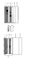
- the inventors have at least a weather-resistant film A, an adhesive layer 1, a film B, an adhesive layer 2, and a protective sheet having a film C having a thickness of 60 ⁇ m or more in this order.
- the width of each of the film B and the film C is made smaller than the width of the weather resistant film A, and the width of the film C is made larger than the width of the film B.
- the present invention [1] least, weatherable film A, adhesive layer 1, a film B, the adhesive layer 2, and the thickness is 60 ⁇ m or more film C A protective sheet having in this order, the width W A of the weather resistant film , the width W B of the film B, and the width W C of the film C is a protective sheet having a relation of W a> W C> W B , [2]
- the ratio of the width W B to the width W C (W B / W C ) is 0.65 or more and less than 1.0, and the difference between the width W C and the width W B (W C ⁇ W B ) is 32 mm or less, the protective sheet according to the above [1], [3]
- the ratio of the width W C to the width W A (W C / W A ) is 0.70 or more and less than 1.0, and the difference between the width W A and the width W C (W A ⁇ W C ) is The protective sheet according to [1] or [2], which is 80 mm or less, [4] The
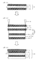
- a method for producing a protective sheet comprising the following steps (1) to (4): (1) Step of producing a laminate X having the adhesive layer 1 on one surface of the film B and the adhesive layer 2 on the other surface (2) slitting both ends in the width direction of the laminate X, Step (3) for forming laminated body X ′ A weather resistant film A having a width W A wider than the width W X ′ of the laminated body X ′ is formed on the adhesive layer 1, and both ends of the weather resistant film A are adhesive layers. (4) On the adhesive layer 2, a width W C wider than the width W X ′ of the laminate X ′ and narrower than the width W A of the weather resistant film A is bonded onto the adhesive layer 2.
- the release sheet 1 is formed on the adhesive layer 1 as the laminate X.
- the step (3) The method for producing a protective sheet according to [16], wherein the release sheet 1 is peeled off before and after the step (2), the step of peeling the release sheet 2 before the step (4) is performed.
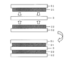
- step (1) includes the following steps (1-1) to (1-3): (1-1) Step of applying adhesive layer 1 composition on release sheet 1 and drying to form adhesive layer 1 (1-2) Applying adhesive layer 2 composition on release sheet 2 Step of drying to form the adhesive layer 2 (1-3) Step of bonding the adhesive layer 1 and the adhesive layer 2 to the film B to obtain a laminate X [19] [1] to [10] ]
- a protective sheet such as a solar cell protective sheet and a curled product of a laminate such as a solar cell module using the protective sheet are suppressed, and a protective sheet having a good appearance, in particular, the protective sheet is used.
- a solar cell module can be provided.
- the protective sheet which can suppress the delamination of the laminated body end surface of a protective sheet can be provided.
- Sectional drawing which shows one Embodiment of the protection sheet of this invention
- Sectional drawing which shows one use example of the protection sheet of this invention
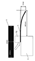
- the figure explaining the evaluation method of bending length The figure explaining the evaluation method of load bearing dent
- the figure which shows one Embodiment of each process of the manufacturing method of the protection sheet of this invention The figure which shows one Embodiment of the process (1) of the manufacturing method of the protection sheet of this invention
- Sectional drawing which shows an example of the protective sheet obtained by the manufacturing method of the conventional protective sheet
- a protective sheet composed of a laminate of a plurality of films due to the difference in thermal shrinkage between the constituent films, for example, when a high temperature environment is used, significant curling may occur.
- a solar cell module curling is likely to occur because the weather-resistant film on the exposed surface side is different from other film layers such as a moisture-proof layer.
- the present inventors made at least a weather resistant film A, an adhesive layer 1, a film B, an adhesive layer 2, and a film C having a thickness of 60 ⁇ m or more in this order in the configuration of the protective sheet.
- the width of each of the film B and the film C other than the weather resistant film A is made smaller than the width of the weather resistant film A, and the width of the film C is made larger than the width of the film B.
- the sealant (20) on the electronic device (30) is shorter than the width of the weather resistant film A (1) during vacuum lamination.
- the present invention includes at least a weather-resistant film A (1), an adhesive layer 1 (21), a film B (3), an adhesive layer 2 (22), and a thickness of 60 ⁇ m or more.
- each constituent film will be described in detail.
- the protective sheet of the present invention has a weather resistant film A having hydrolysis resistance and weather resistance (hereinafter sometimes simply referred to as “weather resistant film”) in order to impart long-term durability.
- weather resistant film is preferably a fluororesin film in terms of weather resistance.
- polytetrafluoroethylene PTFE
- tetrafluoroethylene / perfluoroalkyl vinyl ether copolymer PFA
- FEP tetrafluoroethylene / hexafluoropropylene A copolymer
- FEP tetrafluoroethylene / ethylene copolymer
- EFE tetrafluoroethylene / ethylene copolymer
- PCTFE polychlorotrifluoroethylene
- PVDF polyvinylidene fluoride
- PVF polyvinyl fluoride
- tetrafluoroethylene / ethylene copolymer (ETFE) and tetrafluoroethylene / hexafluoropropylene copolymer (FEP) are more preferably used as the resin.
- a low shrinkable weather resistant base material such as polyethylene naphthalate is suitable in consideration of small changes in properties during vacuum lamination, temperature change and humidity change.
- a film obtained by lowering a shrinkage rate of a polyethylene terephthalate film or a fluorine-based film having a large heat shrinkage rate by prior heat treatment is preferable.
- additives can be added to the weather resistant film as necessary.
- examples of the additive include, but are not limited to, an ultraviolet absorber, a weathering stabilizer, an antioxidant, an antistatic agent, and an antiblocking agent.
- the thickness of the weather resistant film is generally about 20 to 150 ⁇ m, preferably 20 to 100 ⁇ m, more preferably 20 to 60 ⁇ m from the viewpoints of film handling and cost.
- curl of the protective sheet can be suppressed by the presence of the film C described later, even if the weather resistant film is not heat-treated in advance to reduce the thermal shrinkage rate.
- the heat shrinkage rate of the weather resistant film is preferably 0.3 to 5.0%, more preferably 0.5 to 4.0%. Preferably, it is 1.0 to 3.5%.
- the heat shrinkage ratio is (L 0 -L 1 ) ⁇ 100 / L, where L 0 is the sample length before heating, and L 1 is the sample length after heat treatment in an oven for 30 minutes at 150 ° C. It can be calculated from the equation of 0 .
- the film B is laminated on the weather resistant film via the adhesive layer 1.
- a film having a water vapor barrier property or an oxygen barrier property is preferably used.
- polyolefins such as homopolymers or copolymers such as ethylene, propylene and butene; amorphous polyolefins such as cyclic polyolefins; polyesters such as polyethylene terephthalate (PET) and polyethylene naphthalate (PEN); nylon 6 Polyamide such as nylon 66, nylon 12, copolymer nylon; ethylene-vinyl acetate copolymer partial hydrolyzate (EVOH), polyimide, polyetherimide, polysulfone, polyethersulfone, polyetheretherketone, polycarbonate, polyvinyl A resin film made of butyral, polyarylate, fluororesin, acrylic resin, biodegradable resin, or the like, or a moisture-proof film having an inorganic layer formed on a
- the protective sheet of the present invention When used as a protective sheet for solar cells, it is preferably a moisture-proof film.
- the thickness of the film B is generally about 5 to 100 ⁇ m, preferably 8 to 50 ⁇ m, more preferably 10 to 25 ⁇ m from the viewpoint of productivity and ease of handling.
- the moisture-proof film As a moisture-proof film, what has at least the inorganic layer formed in at least one surface of a base material and a base material is preferable. Since it is desired that the solar cell protective sheet has high moisture resistance for a long period of time, the initial moisture resistance needs to be a certain level or more. Therefore, the moisture-proof film is preferably a water vapor transmission rate is less than 0.1g / m 2 / day, more preferably not more than 0.05g / m 2 / day, more preferably, 0.03 g / m 2 / Day or less. The moisture-proof film is preferably transparent when the solar cell protective sheet is used as a front sheet used on the light receiving surface side.
- a resin film is preferable, and any material can be used without particular limitation as long as it is a resin that can be used for an ordinary solar cell material.
- polyolefins such as homopolymers or copolymers such as ethylene, propylene and butene; amorphous polyolefins such as cyclic polyolefins; polyesters such as polyethylene terephthalate (PET) and polyethylene naphthalate (PEN); nylon 6 , Polyamides such as nylon 66, nylon 12 and copolymer nylon; ethylene-vinyl acetate copolymer partial hydrolyzate (EVOH), polyimide, polyetherimide, polysulfone, polyethersulfone, polyetheretherketone, polycarbonate, polyvinyl Examples include butyral, polyarylate, fluororesin, acrylic resin, biodegradable resin, and the like, and among them, a thermoplastic resin is preferable.
- polyesters, polyamides, and polyolefins are preferable from the viewpoints of film properties and costs
- polyethylene terephthalate (PET) and polyethylene naphthalate (PEN) are particularly preferable from the viewpoints of surface smoothness, film strength, heat resistance, and the like.
- additives can be added to the substrate as necessary.
- the additive include, but are not limited to, an antistatic agent, an ultraviolet absorber, a plasticizer, a lubricant, a filler, a colorant, a weathering stabilizer, an antiblocking agent, and an antioxidant.
- UV absorbers examples include various types such as benzophenone-based, benzotriazole-based, triazine-based, salicylic acid ester-based, and various commercially available products can be applied.
- the resin film as the substrate is formed by using the above raw materials, but may be unstretched or stretched. Further, it may be either a single layer or a multilayer.
- a substrate can be produced by a conventionally known method. For example, the raw material is melted by an extruder, extruded by an annular die or a T die, and rapidly cooled to be substantially amorphous and not oriented. A stretched film can be produced. Further, by using a multilayer die, it is possible to produce a single layer film made of one kind of resin, a multilayer film made of one kind of resin, a multilayer film made of various kinds of resins, and the like.
- the unstretched film is subjected to a known method such as uniaxial stretching, tenter sequential biaxial stretching, tenter simultaneous biaxial stretching, tubular simultaneous biaxial stretching, or the like.
- a film stretched in a uniaxial direction or a biaxial direction can be produced by stretching in a direction (horizontal axis) perpendicular thereto.
- the draw ratio can be arbitrarily set, the thermal shrinkage at 150 ° C. in at least one of the width direction and the length direction of the film is preferably 0.01 to 5%, and preferably 0.01 to 2%. It is more preferable.
- a biaxially stretched polyethylene terephthalate film a biaxially stretched polyethylene naphthalate film, a polyethylene terephthalate and / or a coextruded biaxially stretched film of polyethylene naphthalate and another resin is preferable.
- the thickness of the substrate is generally 5 to 100 ⁇ m, preferably 8 to 50 ⁇ m, more preferably 10 to 25 ⁇ m from the viewpoint of productivity and ease of handling.
- the anchor coat layer includes a solvent-based or water-based polyester resin; an alcoholic hydroxyl group-containing resin such as an isocyanate resin, a urethane resin, an acrylic resin, a modified vinyl resin, or a vinyl alcohol resin; a vinyl butyral resin, a nitrocellulose resin, or an oxazoline group Resins, carbodiimide group-containing resins, melamine group-containing resins, epoxy group-containing resins, modified styrene resins, modified silicone resins and the like can be used alone or in combination of two or more.
- an alcoholic hydroxyl group-containing resin such as an isocyanate resin, a urethane resin, an acrylic resin, a modified vinyl resin, or a vinyl alcohol resin
- a vinyl butyral resin a nitrocellulose resin, or an oxazoline group
- an alkyl titanate, a silane coupling agent, a titanium coupling agent, an ultraviolet absorber, a weathering stabilizer, a lubricant, an anti-blocking agent, an antioxidant and the like can be added to the anchor coat layer as necessary.
- the ultraviolet absorber, weather stabilizer and antioxidant the same ones as those used for the aforementioned substrate can be used, and the weather stabilizer and / or ultraviolet absorber is copolymerized with the resin described above.
- the polymer type can also be used.
- the thickness of the anchor coat layer is preferably 10 to 200 nm, and more preferably 10 to 100 nm, from the viewpoint of improving the adhesion with the inorganic layer.
- a known coating method is appropriately adopted as the formation method.
- a reverse roll coater, a gravure coater, a rod coater, an air doctor coater, or a coating method using a spray can be used.
- the substrate may be immersed in a resin solution.
- the solvent can be evaporated using a known drying method such as hot air drying at a temperature of about 80 to 200 ° C., heat drying such as hot roll drying, or infrared drying.
- the crosslinking process by electron beam irradiation can also be performed.
- the formation of the anchor coat layer may be a method performed in the middle of the substrate production line (inline) or a method performed after the substrate production (offline).
- Examples of the inorganic substance constituting the inorganic layer include silicon, aluminum, magnesium, zinc, tin, nickel, titanium, etc .; or their oxides, carbides, nitrides; or mixtures thereof.
- silicon oxide, silicon nitride, silicon oxynitride, aluminum oxide, and diamond-like carbon are preferable because they are transparent.
- silicon oxide, silicon nitride, silicon oxynitride, and aluminum oxide are preferable because high gas barrier properties can be stably maintained.
- any method such as a vapor deposition method and a coating method can be used, but the vapor deposition method is preferable in that a uniform thin film having a high gas barrier property can be obtained.
- This vapor deposition method includes any method such as physical vapor deposition (PVD) or chemical vapor deposition (CVD). Examples of physical vapor deposition include vacuum vapor deposition, ion plating, and sputtering, and chemical vapor deposition includes plasma CVD using plasma and a catalyst that thermally decomposes a material gas using a heated catalyst body. Examples include chemical vapor deposition (Cat-CVD).
- the inorganic layer may be a single layer or a multilayer. In the case of multiple layers, the same film formation method may be used, or a different film formation method may be used for each layer. From the viewpoint of sex.
- the multilayer structure includes an inorganic layer formed by a vacuum deposition method, an inorganic layer formed by a chemical vapor deposition method, and an inorganic layer formed by a vacuum deposition method in this order. Is preferred.
- each layer may consist of the same inorganic substance, or may consist of a different inorganic substance.
- the thickness of the inorganic layer is preferably 10 to 1000 nm, more preferably 20 to 800 nm, and still more preferably 20 to 600 nm, from the viewpoint of stable moisture resistance.
- the film C is a film bonded to the film B via the adhesive layer 2, and a resin film having a thickness of 60 ⁇ m or more is used.
- the film C preferably has a modulus of elasticity at 23 ° C. of 2.0 GPa or more.
- the film C has an effect of suppressing deformation against shrinkage of the other constituent layers, and thus is excellent in curling generation suppression.
- the thickness of the film C necessary for suppressing the occurrence of curling is preferably 60 to 300 ⁇ m, more preferably about 75 to 250 ⁇ m, and more preferably 100 to 300 ⁇ m from the viewpoint of film handling and cost. 200 ⁇ m.
- the elastic modulus refers to the tensile elastic modulus obtained from the slope of the linear portion of the stress-strain curve, and can be obtained by a tensile test method based on JIS K7161: 1994.
- the material of the film C include polyesters such as polyethylene terephthalate (PET) and polyethylene naphthalate (PEN); polyamides such as nylon 6, nylon 66, nylon 12 and copolymer nylon; ethylene-vinyl acetate copolymer Combined partial hydrolyzate (EVOH), polyimide, polyetherimide, polysulfone, polyethersulfone, polyetheretherketone, polycarbonate, polyvinyl butyral, polyarylate, fluororesin, acrylate resin, biodegradable resin, and An inorganic material such as talc or an organic or inorganic material such as a filler may be added to the resin to improve the elastic modulus reinforcing effect.
- PET polyethylene terephthalate
- PEN polyethylene naphthalate
- EVOH ethylene-vinyl acetate copolymer Combined partial hydrolyzate
- polyimide polyetherimide
- polysulfone polysulfone
- the film C is selected from polyethylene naphthalate, polyethylene terephthalate, etc., or polypropylene (PP), polylactic acid (PLA), polyvinyl fluoride (PVF), polyvinylidene fluoride (PVDF), cellulose butyrate (CAB), etc. It is preferable to include one or two or more kinds of resins, and it is preferable to contain 50% by mass or more of the resins. Furthermore, although what formed into a film the resin composition which mix
- the protective sheet of the present invention has an adhesive layer 1 between the weather-resistant film A and the film B and an adhesive layer 2 between the film B and the film C.
- the adhesive layer 1 and the adhesive layer 2 may be the same or different in composition and thickness, but are the same in composition and thickness from the viewpoint of balance of the protective sheet such as prevention of curling. It is preferable.
- the adhesive layer 1 and the adhesive layer 2 may be simply referred to as “adhesive layer”.
- a weather-resistant film and a film B such as a moisture-proof film
- a film B and a film C are laminated via an adhesive layer.
- an adhesive diluted with a solvent is applied on each film, for example, on the substrate side of film C and film B to a predetermined thickness, and the solvent is evaporated by drying usually in the range of 70 ° C to 140 ° C.
- An adhesive layer is formed on the film.
- another resin film or the like is bonded to the adhesive layer side.
- it is prepared through curing at a predetermined temperature. Curing is performed, for example, in the range of 30 ° C. to 80 ° C. for 1 day to 1 week.
- the accumulated residual strain is, for example, a protective sheet used as a protective sheet for solar cells.
- the film when used or stored in a high temperature and high humidity environment, it acts as a stress on each laminated interface.
- residual strain when residual strain accumulates in the film, the film shrinks in a high temperature and high humidity environment, applies stress to the inorganic layer of the moisture-proof film, causes defects in the inorganic layer, and causes a decrease in moisture-proof performance. .
- the degree of softness and thickness is reduced to some extent from the viewpoint of reducing the transmission of stress due to film shrinkage resulting from residual strain to the inorganic layer and protecting the inorganic layer and preventing deterioration of moisture resistance. It is preferable to laminate a weather resistant film (fluorine-based resin film) and a moisture-proof film through an adhesive layer.
- the adhesive layer preferably has a tensile storage modulus of 5.0 ⁇ 10 4 to 5.0 ⁇ 10 5 Pa at 100 ° C., a frequency of 10 Hz, and a strain of 0.1%.
- an adhesive layer is formed when laminating components such as a resin film constituting a protective sheet. Does not flow, and the layer thickness can be kept uniform. Further, if the tensile storage modulus at 100 ° C., frequency 10 Hz, and strain 0.1% of the adhesive layer is 5.0 ⁇ 10 5 Pa or less, it occurs due to shrinkage of the opposing film through the adhesive layer. By absorbing the stress with the adhesive layer, damage to the inorganic layer can be prevented.
- the tensile storage modulus at 100 ° C., frequency 10 Hz, and strain 0.1% of the adhesive layer is preferably 7.0 ⁇ 10 4 Pa to 5.0 ⁇ 10 5 Pa, and 1.0 ⁇ 10 5 Pa. More preferably, it is ⁇ 5.0 ⁇ 10 5 Pa.
- the adhesive layer has a tensile storage elastic modulus of 1.0 ⁇ 10 6 Pa or more at 20 ° C., a frequency of 10 Hz, and a strain of 0.1% from the viewpoint of maintaining adhesive strength at normal temperature (20 ° C.). preferable.
- inferior moisture resistance of the protective sheet inferior moisture resistance of the adhesive itself may be mentioned. For this, it is effective to select an adhesive that is difficult to hydrolyze.
- the adhesive used for the adhesive layer is preferably a pressure-sensitive adhesive that has a certain degree of softness and adheres by van der Waals force.
- Adhesives are adhesives that do not use water, solvents, heat, etc., are bonded at a normal temperature for a short time with a slight pressure, and get wet with the adherend (fluidity).
- a solid property that resists peeling.
- adhesives such as solution-type adhesives, thermosetting adhesives, and hot-melt adhesives solidify due to chemical reaction, solvent volatilization, temperature changes, etc.
- adhesives are semi-solid and require a solidification process. In other words, the state does not change even after the bonding is formed.
- the term “main component” is intended to allow other components to be included within a range that does not hinder the effects of the present invention.
- the specific content is not limited, the main component is generally 50 parts by mass or more, preferably 65 parts by mass or more, more preferably 100 parts by mass as a whole of the constituent components of the adhesive layer. Is 80 parts by mass or more and 100 parts by mass or less.
- acrylic pressure-sensitive adhesive examples include a main monomer component having a low glass transition point (Tg) that imparts tackiness, a comonomer component having a high Tg that imparts adhesiveness and cohesive force, and a functional group-containing monomer for improving crosslinking and adhesion.
- Tg glass transition point
- comonomer component having a high Tg that imparts adhesiveness and cohesive force
- a functional group-containing monomer for improving crosslinking and adhesion examples of the acrylic (co) polymer.
- acrylic acid esters such as ethyl acrylate, butyl acrylate, amyl acrylate, 2-ethylhexyl acrylate, and octyl acrylate. These may be used alone or in combination of two or more.
- comonomer component of the acrylic (co) polymer methyl acrylate, methyl methacrylate, ethyl methacrylate, butyl methacrylate, 2-ethylhexyl methacrylate, cyclohexyl methacrylate, benzyl methacrylate, vinyl acetate, styrene, acrylonitrile Etc. These may be used alone or in combination of two or more.
- Examples of the functional group-containing monomer component of the acrylic (co) polymer include, for example, carboxyl group-containing monomers such as acrylic acid, methacrylic acid, maleic acid, and itaconic acid, 2-hydroxyethyl (meth) acrylate, 2-hydroxy Examples thereof include hydroxyl group-containing monomers such as propyl (meth) acrylate and N-methylolacrylamide, acrylamide, methacrylamide and glycidyl methacrylate. These may be used alone or in combination of two or more.
- the initiator used for polymerization of the monomer component of the acrylic (co) polymer examples include azobisisobutylnitrile, benzoyl peroxide, di-t-butyl peroxide, cumene hydroperoxide, and the like.
- the copolymerization form of the acrylic (co) polymer used as the main component of the said acrylic adhesive Any of a random, a block, and a graft copolymer may be sufficient.
- the molecular weight when the acrylic pressure-sensitive adhesive is the above-mentioned acrylic (co) polymer is preferably 300,000 to 1,500,000 in terms of mass average molecular weight, and more preferably 400,000 to 1,000,000. preferable. By setting the mass average molecular weight within the above range, adhesion to the adherend and adhesion durability can be secured, and floating and peeling can be suppressed.
- the content of the functional group-containing monomer component unit is preferably in the range of 1 to 25% by mass.
- adhesion to the adherend and degree of crosslinking are ensured, and the tensile storage modulus of the adhesive layer is 5.0 ⁇ 10 4 to 5.0 ⁇ at 100 ° C.
- the value can be in the range of 10 5 Pa.
- a factor for forming the bond is considered to be due to a reaction between a defective portion of an inorganic layer such as a SiO x layer and a hydroxyl group in the adhesive layer.
- the number of reactive functional groups in the adhesive may be reduced, and it is preferable to reduce the number of unreacted functional groups after application and curing of the adhesive layer.
- the adhesive layer in the present invention preferably contains an ultraviolet absorber.
- the adhesive layer may be formed by directly applying to the weather-resistant film, film B or film C, or the release treatment of the release sheet from which the adhesive has been released. It can also be formed by coating the surface and bonding it to a weather resistant film or the like.
- the adhesive to be coated (hereinafter referred to as a coating solution) includes an organic solvent system, an emulsion system, and a solventless system, but an organic solvent system is desirable for uses such as a solar cell sheet that requires water resistance.
- organic solvent used in the organic solvent-based coating liquid examples include toluene, xylene, methanol, ethanol, isobutanol, n-butanol, acetone, methyl ethyl ketone, ethyl acetate, and tetrahydrofuran. These may be used alone or in combination of two or more.
- the coating liquid is preferably prepared using these organic solvents so that the solid content concentration is in the range of 10 to 50% by mass.
- Coating of the coating liquid is, for example, conventionally known coating methods such as bar coating, roll coating, knife coating, roll knife coating, die coating, gravure coating, air doctor coating, doctor blade coating, etc. It can be done by a method.
- the adhesive layer is formed by drying treatment usually at a temperature of 70 to 140 ° C. for about 1 to 5 minutes.
- the thickness of the adhesive layer is preferably 2 to 30 ⁇ m, more preferably 4 to 25 ⁇ m, still more preferably 6 to 20 ⁇ m from the viewpoint of obtaining a sufficient adhesive force.
- the protective sheet of the present invention has at least the weather-resistant film A, the adhesive layer 1, the film B, the adhesive layer 2, and the film C having a thickness of 60 ⁇ m or more in this order, and the width of the weather-resistant film.
- W A , the width W B of the film B , and the width W C of the film C have a relationship of W A > W C > W B.
- W A , W B, and W C do not satisfy the above relationship, or when the thickness of the film C is less than 60 ⁇ m, it is obtained due to the difference in the thermal shrinkage rates of the weather resistant film, the film B, and the film C. In the laminate, the curl is remarkably generated or delamination occurs, and the problem of the present invention cannot be solved.
- the width W A of each of the weather resistant film of a width W C of the width W B and film C of the film B it is necessary to be smaller than the width W A of each of the weather resistant film of a width W C of the width W B and film C of the film B.
- the film C has an appropriate width W C , the shrinkage stress of the weather resistant film can be suppressed and curling can be suppressed.
- the ratio of the width W C to the width W A (W C / W A ) is 0.70 or more and less than 1.0, and the width W A and the width
- the difference of W C (W A ⁇ W C ) is preferably 100 mm or less.
- W C / W A is 0.80 or more and less than 1.0, and ac is 80 mm or less, more preferably W C / W A is 0.85 or more, 0 .95 or less, and the difference between the width W A and the width W C is 50 mm or less.
- the width W C of the film C needs to be larger than the width W B of the film B.
- the ratio of the width W B to the width W C (W B / W C ) is 0.65 or more, 1
- the difference between the width W C and the width W B (W C ⁇ W B ) is preferably 32 mm or less.
- W B / W C is 0.75 or more and less than 1.0, and the difference between the width W C and the width W B is 30 mm or less, and more preferably, W B / W C is It is 0.80 or more and 0.99 or less, and W C -W B is 25 mm or less.
- the “film width” means the length in the lateral direction with respect to the length direction of the film unwound from the roll when the protective sheet is provided in a roll, and is provided in a single sheet. The short side of the four sides.
- the shrinkage stress of the weather resistant film can be sufficiently suppressed, and the ratio of the thickness of the weather resistant film to the thickness of the film C (the thickness of the weather resistant film / the thickness of the film C) from the viewpoint of handling and cost.
- (Thickness) is preferably 2.0 or less, more preferably 1.0 or less, still more preferably 0.75 or less, particularly preferably 0.20 or more and 0.75 or less.
- the thickness of the entire protective sheet is not particularly limited, but is preferably 90 to 600 ⁇ m, more preferably 100 to 400 ⁇ m, and further preferably 120 to 320 ⁇ m.
- the film B is a moisture-proof film having an inorganic layer on at least one surface of the substrate
- damage to the inorganic layer during storage and use of the protective sheet can be reduced, which is preferable.
- the sealing material-integrated protective sheet of the present invention is obtained by further laminating a sealing material layer on the film C side of the protective sheet of the present invention described above.
- the efficiency of the vacuum laminating process of the electronic device can be improved.
- the electronic device include display elements such as EL elements and liquid crystal display elements, solar cells, touch panels, and the like.
- display elements such as EL elements and liquid crystal display elements, solar cells, touch panels, and the like.
- examples of the sealing material constituting the sealing material layer include a silicone resin-based sealing material, an ethylene-vinyl acetate copolymer, and ethylene and ⁇ -olefin.
- a random copolymer etc. are mentioned.
- examples of the ⁇ -olefin include propylene, 1-butene, 1-pentene, 1-hexene, 1-heptene, 1-octene, 1-nonene, 1-decene, 3-methyl-butene-1, 4-methyl -Pentene-1 and the like.
- the width W D of the encapsulating material layer is preferably smaller than the width W A of the weather resistant film and larger than the width W C of the film C.
- the thickness of the laminated sealing material layer is preferably 200 to 750 ⁇ m, more preferably 300 to 600 ⁇ m, from the viewpoint of protecting the electronic device.
- a known method can be used as a method for laminating the sealing material layer on the protective sheet of the present invention. For example, what is necessary is just to laminate
- the adhesive layer it is possible to use the same adhesive as the above-mentioned adhesive layer, or a known adhesive such as a solution type adhesive, a thermosetting adhesive, or a hot melt adhesive. it can.
- the adhesive preferably includes a polyurethane adhesive, and more preferably includes a polyurethane adhesive as a main component.
- the roll-like material of the present invention is obtained by winding the protective sheet of the present invention or the protective material integrated protective sheet described above. By making it into a roll-like product, the subsequent processability, transportability, and productivity can be improved, and the appearance can be easily protected.
- the winding length is preferably 50 m or more, and more preferably 100 m or more.
- the roll-like product with a cover sheet of the present invention is a roll-shaped product obtained by winding the protective sheet of the present invention or the protective material-integrated protective sheet described above, and is weatherproof among the surfaces of the roll-shaped product. At least a part of the part corresponding to the part from which the film protrudes is covered with a cover sheet having a bending length measured under the following conditions of 70 mm or less and a load-bearing dent of 0.1 or less. is there.
- the bending length is an index indicating how easily the cover sheet or the like is bent.
- the temperature condition of a measurement is about 23 degreeC.
- a plate having a bottom surface of 20 mm ⁇ 20 mm is first placed on the portion of the sample table, and then a 5 kg weight is placed on the plate.
- the height of the plate is about 5 to 15 mm, and the material is not particularly limited, and examples thereof include a glass plate and an iron plate.
- [Load dent] (1) Collect a 100 mm square sample. (2) A sample is placed on a glass plate having a thickness of 20 mm, a steel ball having a diameter of 5 mm and a weight of 0.5 g is placed on the center of the sample, and a load of 2 kg is further applied on the steel ball. (3) The dent “d” (unit: ⁇ m) of the sample is measured, and the ratio “d / t” to the thickness “t” (unit: ⁇ m) of the sample is defined as a load-bearing dent.
- the load bearing dent is an index indicating the difficulty of the dent of the cover sheet or the like.
- the depth “d” of the sample measures the depth of the deepest recess.
- the protective sheet or the sealing material-integrated protective sheet of the present invention described above has a wide weather-resistant film
- the film has a protruding portion that protrudes from the other protective sheet constituting layers. Therefore, the roll-shaped object which wound up the thick protection sheet or sealing material integrated protection sheet of this invention mentioned above also has such a protrusion part. And the roll-shaped thing which has such a protrusion may bend a protrusion part at the time of transportation, etc., or a wrinkle may arise.
- the cover sheet of the present invention at least a part of the surface of the roll-like material corresponding to the location where the weather-resistant film protrudes is covered with the cover sheet, so that the protruding portion is bent during transportation. Or wrinkles are prevented.
- the cover sheet may cover at least a part corresponding to a part where the weather resistant film protrudes, but it is preferable to cover 50% or more of the part, and it is more preferable to cover the whole part. Moreover, a still more preferable aspect is to cover the entire surface of the roll-shaped material.
- the ratio ([W K ] / [W A ]) of the width W k of the cover sheet to the width W A of the weather resistant film is preferably 1 or more, more preferably 1.05 or more. More preferably, it is 15 or more. Further, from the viewpoint of handling properties, [W K ] / [W A ] is preferably 1.5 or less, and more preferably 1.3 or less.
- the object of the present invention can be achieved by covering the surface of the roll-shaped object with the cover sheet. Furthermore, in consideration of the load from the left-right direction of the roll-shaped object, the side surface of the roll-shaped object may be covered with a cover sheet.
- the bending length is preferably 60 mm or less, more preferably 50 mm or less, and further preferably 40 mm or less.
- the load bearing dent is preferably 0.05 or less, and more preferably 0.03 or less.
- the bending length is 5 mm or more, and the load dent is 0.01 or more. It is preferable that the bending length is 10 mm or more, and the load bearing dent is more preferably 0.02 or more.
- Cover sheets include polyolefins such as homopolymers or copolymers of ethylene, propylene, butene, etc .; amorphous polyolefins such as cyclic polyolefin (Cyclo-Olefin-Polymer: COP); polyethylene terephthalate (PET), polyethylene naphthalate Polyester such as (PEN); polyamide such as nylon 6, nylon 66, nylon 12, copolymer nylon; polyimide, triacetyl cellulose (TAC), cellulose diacetate, cellulose acetate butyrate, polyether sulfone, polysulfone, polymethyl Use plastic sheets such as pentene, polyvinyl chloride, polyvinyl acetal, polyether ketone, polymethyl methacrylate, polycarbonate, polyurethane, etc. It can be.
- the thickness of the cover sheet is preferably 50 ⁇ m to 2 mm, more preferably 100 ⁇ m to 1 mm.
- the cover sheet may cause blocking with the roll.
- the cover sheet positioned below the roll-shaped object is likely to cause blocking between the roll-shaped object and the cover sheet due to the weight of the roll-shaped object.
- the cover sheet preferably has a predetermined surface roughness, and specifically, a cover sheet having an arithmetic average roughness Ra of JIS B 0601 of 50 nm or more is suitable.
- the cover sheet preferably has a cushioning property while having a predetermined strength.
- the foamed plastic film based on the plastic sheet illustrated above is suitable.
- a foamed plastic film is opaque, it is suitable also in the point which is easy to distinguish when the transparency of a laminated body is high, the point which is excellent in blocking prevention property, and the point which is excellent also in handling property since it is lightweight.
- the cover sheet only needs to be configured to cover the surface of the roll-shaped object, but the cover sheet and the roll-shaped object are used with a tape or an adhesive so that the state does not collapse during transportation. It is preferable to partially stick together. Moreover, when the cover sheet covers the entire surface of the roll-shaped object, it is preferable to fix both ends of the cover sheet in the length direction with a tape or an adhesive.
- the cover sheet and the weather resistant film preferably satisfy the following conditions (a ′) and / or (b ′).
- a ′ [Bend length of cover sheet] / [Bend length of weather-resistant film] is 2 or less
- b ′ [Load dent of cover sheet] / [Load dent of weather-resistant film] is 2 or less
- (a ′) [the bending length of the cover sheet] / [the bending length of the weather resistant film] is preferably 1 or less, and more preferably 0.1 to 0.6.
- (b ′) [Load dent of cover sheet] / [Load dent of weather resistant film] is more preferably 1 or less, further preferably 0.5 or less, and 0.01 to 0 .2 is even more preferable.
- the method for producing a protective sheet of the present invention includes the following steps (1) to (4).
- a weather resistant film A having a width W A wider than the width W X ′ of the laminated body X ′ is formed on the adhesive layer 1, and both ends of the weather resistant film A are adhesive layers.
- (4) On the adhesive layer 2, a width W C wider than the width W X ′ of the laminate X ′ and narrower than the width W A of the weather resistant film A is bonded onto the adhesive layer 2. Bonding the film C having the film C so that both ends of the film C protrude from both ends of the adhesive layer 2
- step (1) As shown in FIG. 5, laminate X having adhesive layer 1 (21) on one surface of film B (3) and adhesive layer 2 (22) on the other surface. Is made.
- a release sheet which is not illustrated on an adhesive bond layer.
- the laminate X can be produced by applying an adhesive layer composition on the film B (3) and drying it to form an adhesive layer.
- the adhesive layer composition is ionizing radiation curable, it is preferable to irradiate ionizing radiation after drying.
- an adhesive bond layer can also be formed by transferring the adhesive bond layer formed on another base material to the film B.
- the laminated body X when the laminated body X has a release sheet, the laminated body X can also be produced by bonding the release sheet after forming the adhesive layer on the film B (3). As shown in the figure, it is preferable to produce the film by the following steps (1-1) to (1-3). According to the following method, when the film B is a material having poor heat resistance, a laminate X having an adhesive layer on the film B can be easily produced by using a material having excellent heat resistance as the release sheet. This is preferable in terms of points.
- the conveying speed of the film B or the release sheet is preferably 5 to 15 m / min.
- the conveying speed of the film B or the release sheet is preferably 5 to 15 m / min.
- Step (2) both ends in the width direction of the stacked body X are slit to form a stacked body X ′.
- the width of the adhesive layer (21, 22) is narrower than the width of the film B (3) and the release sheet, and the laminate X
- the adhesive layer composition wraps around the back side of the base material, resulting in a manufacturing failure. This is unavoidable for manufacturing reasons.
- the position of the slit is preferably a position where all of the materials constituting the laminate X (film B, adhesive layer, release sheet) can be slit.
- the slit method is not particularly limited and can be performed using a known slitter.
- the release sheet 1 is peeled after the step (2) and before the step (3), and after the step (2) and before the step (4). It is preferable to go through a step of peeling the release sheet 2.
- Step (3) the weather resistant film A having a width W A wider than the width W X ′ of the laminate X ′ is formed on the adhesive layer 1 so that both ends of the weather resistant film A are from both ends of the adhesive layer 1. Paste them together so that they protrude.
- step (4) a film C having a width W C wider than the width W X ′ of the laminate X ′ and narrower than the width W A of the weather-resistant film is formed on the adhesive layer 2. Bonding is performed so that both ends protrude from both ends of the adhesive layer 2. As shown in FIG.
- the weather resistant film (1) has both ends of the adhesive layers (21, 22) and the film B (3) in the width direction. It is a laminated body having a protruding portion 11. Any of the steps (3) and (4) may be performed first.
- the laminate X ′, the weather resistant film and the film C can be bonded together using a known laminating apparatus or the like.
- an EPC (edge position control) device is used to It is preferable to adjust the position of the width between the weather resistant film and the film C.
- the conveyance speed of the laminate X ′ and the weather resistant film is 20 to 30 m / min.
- the conveyance speed of the laminate X ′ and the weather resistant film is 20 to 30 m / min.
- the protective sheet for solar cells which is a preferred embodiment of the protective sheet of the present invention, is at least the weather-resistant film, the adhesive layer 1, the moisture-proof film as the film B, the protective layer 2 and the protection as the film C. What has a film in this order is preferable, and when using for a front sheet
- the solar cell protective sheet of the present invention is intended to further improve physical properties (flexibility, heat resistance, transparency, adhesiveness, etc.), molding processability, economic efficiency, and the like without departing from the spirit of the present invention. Then, other layers may be laminated.
- any layer that can be used for the protective sheet for solar cells is usually usable.
- a sealing material for example, a light collecting material, a conductive material
- layers such as heat transfer materials and moisture adsorbents.
- Various additives can be added to these other layers as necessary. Examples of the additive include, but are not limited to, an antistatic agent, an ultraviolet absorber, a plasticizer, a lubricant, a filler, a colorant, a weathering stabilizer, an antiblocking agent, and an antioxidant.
- the thickness of the protective sheet for solar cells is not particularly limited, but is usually about 90 to 500 ⁇ m, preferably 100 to 400 ⁇ m, more preferably 150 to 350 ⁇ m, and further preferably 200 to 300 ⁇ m. It is used in the form of a sheet.
- the protective sheet for a solar cell of the present invention has an initial moisture-proof property by using, for example, a moisture-proof film having a water vapor permeability of less than 0.1 g / m 2 / day having an inorganic layer as a base material as the film B. , preferably in the water vapor permeability not greater than 0.1g / m 2 / day, more preferably 0.05 g / m of less than 2 / day, more preferably it is assumed to be less than 0.01g / m 2 / day Can do.
- the solar cell protective sheet of the present invention is excellent in initial moisture resistance, and also excellent in moisture resistance and prevention of delamination even in storage in a high temperature and high humidity environment.
- each moisture-proof property in this invention can be evaluated according to various conditions of JIS Z0222 “moisture-proof packaging container moisture permeability test method” and JIS Z0208 “moisture-proof packaging material moisture permeability test method (cup method)”.
- the protective sheet of the present invention can be used as a surface protective sheet for solar cells as it is or by further bonding to a glass plate or the like.
- a solar cell module can be manufactured by using the solar cell protective sheet in a layer structure of a surface protective sheet such as a front sheet or a back sheet, and fixing the solar cell element.
- a solar cell module various types can be exemplified, and preferably, when the solar cell protective sheet of the present invention is used as a front sheet, a sealing material, a solar cell element, The solar cell module produced using the back sheet
- front sheet protecting sheet for solar cell of the present invention
- sealing material sealing resin layer
- solar cell element sealing material (sealing resin layer)
- back sheet back A structure in which a sealing material and a front sheet (protective sheet for solar cell of the present invention) are formed on a solar cell element formed on the inner peripheral surface of the sheet; front sheet (protection for solar cell of the present invention) Sheet) and a solar cell element formed on the inner peripheral surface of the sheet, for example, an amorphous solar cell element formed on a fluororesin transparent protective sheet by sputtering or the like, and a sealing material and a back sheet are formed.
- front sheet protecting sheet for solar cell of the present invention
- back sheet back A structure in which a sealing material and a front sheet (protective sheet for solar cell of the present invention) are formed on a solar cell element formed on the inner peripheral surface of the sheet
- front sheet protectingion for solar cell of the present invention
- Sheet a solar cell element formed on the inner peripheral surface of the sheet, for example, an
- solar cell elements include single crystal silicon type, polycrystalline silicon type, amorphous silicon type, gallium-arsenic, copper-indium-selenium, copper-indium-gallium-selenium, cadmium-tellurium, III-V group and II -VI group compound semiconductor type, dye sensitized type, organic thin film type, and the like.
- the solar cell protective sheet of the present invention is particularly suitably used as a solar cell protective sheet for a flexible solar cell module such as a compound-based power generation element solar cell module or an amorphous silicon type among electronic devices.
- a moisture-proof film having a moisture permeability of less than about 0.1 g / m 2 / day depending on the type of the solar cell power generation element When forming a solar cell module using the solar cell protective sheet of the present invention, a moisture-proof film having a moisture permeability of less than about 0.1 g / m 2 / day depending on the type of the solar cell power generation element. To a highly moisture-proof film of less than about 0.01 g / m 2 / day depending on the type of the device, and an adhesive having an appropriate tensile storage modulus and thickness is laminated and formed.
- the solar cell protective sheet of the present invention may be used for both the front sheet and the back sheet.
- a single layer or a multilayer such as a sheet made of an inorganic material such as metal or glass or various thermoplastic resin films is used. These sheets may be used.
- the metal include tin, aluminum, and stainless steel
- examples of the thermoplastic resin film include single-layer or multilayer sheets of polyester, fluorine-containing resin, polyolefin, and the like.
- the surface of the front sheet and / or the back sheet can be subjected to a known surface treatment such as a primer treatment or a corona treatment in order to improve the adhesion with a sealing material or other members.
- the solar cell module produced by using the solar cell protective sheet of the present invention such as the aforementioned front sheet (protective sheet for solar cell of the present invention) / sealing material / solar cell element / sealing material / back sheet
- the configuration will be described as an example.
- the solar cell protective sheet, sealing material, solar cell element, sealing material, and back sheet of the present invention are laminated, and further, a junction box (from the solar cell element) on the lower surface of the back sheet.
- a terminal box for connecting wiring for taking out the generated electricity to the outside is bonded.
- the solar cell elements are connected by wiring in order to conduct the generated current to the outside. The wiring is taken out through a through hole provided in the backsheet and connected to the junction box.
- a known manufacturing method can be applied, and it is not particularly limited, but in general, the solar cell protective sheet, sealing material, solar cell element, sealing of the present invention.
- the step of vacuum suction and thermocompression bonding is, for example, a vacuum laminator, the temperature is preferably 130 to 180 ° C., more preferably 130 to 150 ° C., the degassing time is 2 to 15 minutes, and the press pressure is 0.05 to 0. .1 MPa, pressing time is preferably 8 to 45 minutes, more preferably 10 to 40 minutes.
- batch type manufacturing equipment, roll-to-roll type manufacturing equipment, and the like can be applied.
- the solar cell module produced by using the solar cell protective sheet of the present invention is installed on a small solar cell represented by a mobile device, a roof or a roof, regardless of the type and module shape of the applied solar cell. It can be applied to various uses such as large solar cells, both indoors and outdoors.
- the protective sheet of this invention can be expand
- Tensile storage elastic modulus of adhesive layer A pressure-sensitive adhesive was applied to a silicone release PET film so as to be 10 g / m 2 , cured at 40 ° C. for 4 days, and then held at 150 ° C. for 30 minutes for adhesion. An agent layer (adhesive layer) was formed. Thereafter, only the adhesive layer is taken out, a predetermined number of sheets are stacked so that the thickness becomes 200 ⁇ m, a sample (4 mm long, 60 mm wide, 200 ⁇ m thick) is prepared, and the obtained sample is manufactured by IT Measurement Co., Ltd.
- Viscoelastic Spectrometer DVA-200 vibration frequency is 10 Hz, strain is 0.1%, heating rate is 3 ° C./min. The stress against the strain applied to the sample up to 180 ° C. was measured, and the tensile storage modulus (MPa) at 100 ° C., frequency 10 Hz, and strain 0.1% was determined from the obtained data.
- MPa tensile storage modulus
- A-1 Fluorine-based resin film Tetrafluoroethylene / ethylene copolymer (ETFE) film (manufactured by Asahi Glass Co., Ltd., trade name: Aflex 50 MW1250DCS, thickness 50 ⁇ m, thermal shrinkage at 150 ° C .: 3.0% )
- A-2 PET film Biaxially stretched polyester film (manufactured by Mitsubishi Plastics, trade name: T100, thickness 50 ⁇ m, thermal shrinkage at 150 ° C .: 1.0%)
- C-1 Biaxially stretched polyester film (trade name: T100, thickness 50 ⁇ m, heat shrinkage rate at 150 ° C .: 0.3%, manufactured by Mitsubishi Plastics, Inc.) heat-set at 170 ° C.
- C-2 Biaxially stretched polyester film (Mitsubishi Resin, trade name: T100, thickness 75 ⁇ m, heat shrinkage at 150 ° C: 0.3%) heat-set at 170 ° C
- C-3 biaxially stretched polyester A film (trade name: T100, manufactured by Mitsubishi Plastics, thickness 125 ⁇ m, heat shrinkage at 150 ° C .: 0.3%) heat-set at 170 ° C.
- Isotactic polypropylene resin Isotactic To the polypropylene resin, titanium oxide (8% by mass) as a whitening agent and ultrafine titanium oxide (particle diameter: 0.01 to 0.06 ⁇ m, 3% by mass) as an ultraviolet absorber. In addition, other additives are added, and kneaded thoroughly to prepare a polypropylene resin composition. Then, the polypropylene resin composition is extruded with an extruder to obtain an unstretched polypropylene resin film having a thickness of 125 ⁇ m. Manufactured.
- Coronate L (trade name: Nippon Polyurethane Industry Co., Ltd., solid content: 75% by mass) was added as an isocyanate-based crosslinking agent to prepare an adhesive.
- a biaxially stretched polyethylene naphthalate film made by Teijin DuPont, “Q51C12”
- the produced moisture-proof film (B-1) had a water vapor transmission rate of 0.01 g / m 2 / day.
- B-2 Biaxially stretched polyester film (trade name: T100, thickness 50 ⁇ m, heat shrinkage rate at 150 ° C .: 0.3%, manufactured by Mitsubishi Plastics, Inc.) heat-set at 170 ° C.
- Coating solution “GOHSENOL” manufactured by Nippon Gosei Co., Ltd. (degree of saponification: 97.0 to 98.8 mol%, degree of polymerization: 2400) was added to 2810 g of ion-exchanged water and added to an aqueous solution obtained by heating and dissolving. While stirring at ° C, 645 g of 35 mol% hydrochloric acid was added. Subsequently, 3.6 g of butyraldehyde was added with stirring at 10 ° C., and after 5 minutes, 143 g of acetaldehyde was added dropwise with stirring to precipitate resin fine particles.
- Glass A cover glass TCB09331 (3.2 mm thickness) manufactured by AGC Fabritech Co., Ltd. was used, and the glass was cut into the same size as the weather resistant film used in each of the examples and comparative examples.
- Example 1 A pressure-sensitive adhesive was applied to a 38 ⁇ m-thick silicone release PET film (Nakamoto Pax, NS-38 + A, melting point 262 ° C., width 328 mm) to a thickness of 10 ⁇ m, dried and a pressure-sensitive adhesive layer (adhesive layer 1 And a SiO x surface of a film B-1 (moisture-proof film, width: 328 mm) having a thickness of 12 ⁇ m was bonded to the adhesive surface. The thickness of the adhesive on SiO X back side of the silicone release PET film with moisture-proof film.
- the coating is 10 [mu] m, dried to form a pressure-sensitive adhesive layer (adhesive layer 2), thickness 125 ⁇ m on its adhesive surface
- a heat shrinkage reduction PET film C-3 (width: 330 mm) was bonded.
- peeling off the silicone release PET film SiO X side of the film B-1 the thickness of 50 ⁇ m weatherproof film A-1 (width: 380 mm, thermal shrinkage: 3.0%) was bonded.
- curing was performed at 40 ° C. for 4 days, and a protective sheet E-1 having a thickness of 207 ⁇ m was produced.
- the lengths of the weather resistant film A-1, the film B-1, the adhesive layer 1 and the adhesive layer 2 are substantially the same.
- the produced protective sheet E-1 was placed flat in an oven maintained at 150 ° C. and allowed to stand for 5 minutes, and the curl value was measured. Further, the layers were laminated in the order of glass, sealing material, and protective sheet E-1 (weather-resistant film exposed side), and vacuum lamination was performed at 150 ° C. for 15 minutes to evaluate the appearance. Table 1 shows the structure, width, and thickness of each layer, and Table 2 shows the results.
- Example 2 A protective sheet E-2 having a thickness of 207 ⁇ m was produced in the same manner as in Example 1 except that the width of the film B-1 was changed to 326 mm.
- Table 1 shows the relationship between the structure, width, and thickness of each layer, and Table 2 shows the results of the same evaluation as in Example 1.
- Example 3 A protective sheet E-3 having a thickness of 207 ⁇ m was produced in the same manner as in Example 1 except that the width of the film B-1 was changed to 320 mm.
- Table 1 shows the relationship between the structure, width, and thickness of each layer, and Table 2 shows the results of the same evaluation as in Example 1.
- Example 4 A protective sheet E-4 having a thickness of 207 ⁇ m was produced in the same manner as in Example 1 except that the width of the film B-1 was changed to 310 mm.
- Table 1 shows the relationship between the structure, width, and thickness of each layer, and Table 2 shows the results of the same evaluation as in Example 1.
- Example 5 A protective sheet E-5 having a thickness of 207 ⁇ m was produced in the same manner as in Example 1 except that the width of the film B-1 was changed to 296 mm.
- Table 1 shows the relationship between the structure, width, and thickness of each layer, and Table 2 shows the results of the same evaluation as in Example 1.
- Example 6 Example 1 except that the width of the film B-1 was changed to 70 mm, the width of the heat shrinkage-reducing PET film C-3 was changed to 90 mm, and the width of the weather resistant film A-1 was changed to 100 mm.
- a protective sheet E-6 having a thickness of 207 ⁇ m was prepared. Table 1 shows the relationship between the structure, width, and thickness of each layer, and Table 2 shows the results of the same evaluation as in Example 1.
- Example 7 A protective sheet E-7 having a thickness of 207 ⁇ m was prepared in the same manner as in Example 1 except that the width of the film B-1 was changed to 346 mm and the width of the heat shrinkage-reducing PET film C-3 was changed to 350 mm.
- Table 1 shows the relationship between the structure, width, and thickness of each layer, and Table 2 shows the results of the same evaluation as in Example 1.
- Example 8 A protective sheet E-8 having a thickness of 207 ⁇ m was produced in the same manner as in Example 5 except that the width of the heat shrinkage-reducing PET film C-3 was changed to 300 mm.
- Table 1 shows the relationship between the structure, width, and thickness of each layer, and Table 2 shows the results of the same evaluation as in Example 1.
- Example 9 A protective sheet E-9 having a thickness of 207 ⁇ m was prepared in the same manner as in Example 2 except that the weather resistant film A-1 was changed to PET film A-2 (width: 380 mm, heat shrinkage: 1.5%). .
- Table 1 shows the relationship between the structure, width, and thickness of each layer, and Table 2 shows the results of the same evaluation as in Example 1.
- Example 10 A protective sheet E-10 having a thickness of 157 ⁇ m was produced in the same manner as in Example 2 except that the heat shrinkage-reducing PET film C-3 was changed to a biaxially stretched polyester film C-2 having a thickness of 75 ⁇ m.
- Table 1 shows the relationship between the structure, width, and thickness of each layer, and Table 2 shows the results of the same evaluation as in Example 1.
- Example 11 A protective sheet E- having a thickness of 207 ⁇ m was obtained in the same manner as in Example 2 except that the heat shrinkage-reducing PET film C-3 was changed to isotactic polypropylene resin C-4 (width: 330 mm, elastic modulus: 1.5 GPa). 11 was produced. Table 1 shows the relationship between the structure, width, and thickness of each layer, and Table 2 shows the results of the same evaluation as in Example 1.
- Example 12 A protective sheet E-12 having a thickness of 245 ⁇ m was produced in the same manner as in Example 2 except that the film B-1 was changed to a heat shrinkage-reducing PET film B-2 (width: 326 mm) having a thickness of 50 ⁇ m.
- Table 1 shows the relationship between the structure, width, and thickness of each layer, and Table 2 shows the results of the same evaluation as in Example 1.
- Comparative Example 1 A protective sheet E-13 having a thickness of 207 ⁇ m was produced in the same manner as in Example 1 except that the width of the film B-1 was changed to 330 mm.
- Table 1 shows the relationship between the structure, width, and thickness of each layer, and Table 2 shows the results of the same evaluation as in Example 1.
- Comparative Example 2 A protective sheet E-14 having a thickness of 207 ⁇ m was prepared in the same manner as in Example 1 except that the width of the film B-1 was changed to 376 mm and the width of the heat shrinkage-reducing PET film C-3 was changed to 380 mm.
- Table 1 shows the relationship between the structure, width, and thickness of each layer, and Table 2 shows the results of the same evaluation as in Example 1.
- Comparative Example 3 A protective sheet E-15 having a thickness of 132 ⁇ m was prepared in the same manner as in Example 2 except that the heat shrinkage reduction PET film C-3 was changed to a biaxially stretched polyester film C-1 having a thickness of 50 ⁇ m.
- Table 1 shows the relationship between the structure, width, and thickness of each layer, and Table 2 shows the results of the same evaluation as in Example 1.
- Examples 1 to 12 within the scope of the present invention are all excellent in curling prevention and appearance after vacuum lamination, and the width of each layer constituting the protective sheet is Comparative Examples 1 to 3 which are not within the specified range of the present invention were inferior in anti-curl performance or appearance after vacuum lamination.
- Example 13 A pressure-sensitive adhesive was applied to the surface of the protective sheet E-1 produced in Example 1 on the film C-3 side so as to have a thickness of 5 ⁇ m and dried to form a pressure-sensitive adhesive layer (adhesive layer).
- a sealing material D-1 having a width of 350 mm was laminated on the adhesive surface of the formed layer and cured at 40 ° C. for 4 days to produce a sealing material-integrated protective sheet F-1 having a thickness of 700 ⁇ m.
- the obtained sealing material-integrated protective sheet F-1 had good adhesion between the protective sheet E-1 and the sealing material layer. Further, when the appearance after vacuum lamination was evaluated for the sealing material-integrated protective sheet F-1, the same evaluation as in Example 1 was obtained while the workability was superior to that in Example 1.
- K-1 Polyethylene foam sheet (Pollen Chemical Industries, Pollen sheet, thickness 700 ⁇ m, width 480 mm)
- K-2 Polypropylene film (manufactured by KOKUGO, polypropylene sheet (product code: 07-175-02), thickness 500 ⁇ m, width 480 mm)
- K-3 Transparent polyester film (Made by Mitsubishi Plastics, Diafoil T100, thickness 380 ⁇ m, width 480 mm)
- K-4 Polyethylene film (manufactured by TGK, product code: 125-18-18-01, thickness 30 ⁇ m, width 250 mm)
- the cover sheet and the weather resistant film A-1 are cut into strips having a width of 20 mm and a length of 120 mm, and the measurement sample S of the cover sheet and the weather resistant film A-1 is obtained.
- the sample S is placed on a table 71 having a height of 100 mm or more so that a portion of the sample S having a width of 20 mm ⁇ a length of 100 mm protrudes from the table, and the bottom surface of the sample S is 20 mm ⁇ 20 mm.
- an iron plate having a height of 10 mm was placed thereon, and a weight 72 having a weight of 5 kg was placed thereon.
- Example 14 A pressure-sensitive adhesive was applied to a 38 ⁇ m-thick silicone release PET film (Nakamoto Pax, NS-38 + A, melting point 262 ° C., width 328 mm) to a thickness of 10 ⁇ m, dried and a pressure-sensitive adhesive layer (adhesive layer 1 And a SiO x surface of a film B-1 (moisture-proof film, width: 328 mm) having a thickness of 12 ⁇ m was bonded to the adhesive surface. The thickness of the adhesive on SiO X back side of the silicone release PET film with moisture-proof film.
- the coating is 10 [mu] m, dried to form a pressure-sensitive adhesive layer (adhesive layer 2), thickness 125 ⁇ m on its adhesive surface
- a heat shrinkage reduction PET film C-3 (width: 330 mm) was bonded.
- the silicone release PET film on the SiO x surface side of the film B-1 was peeled off, and a weather resistant film A-1 (width: 380 mm, heat shrinkage: 3.0%) having a thickness of 50 ⁇ m was bonded and weather resistant.
- a laminate having the structure of adhesive film A-1 / adhesive layer 1 / film B-1 / adhesive layer 2 / film C-3 was obtained.
- the laminate was wound into a core having an outer diameter of 172.4 mm to obtain a 200 m roll.
- Example 15 A roll sheet with a cover sheet of Example 15 was obtained in the same manner as in Example 14 except that K-2 was used as the cover sheet.
- Example 16 A roll with a cover sheet of Example 16 was obtained in the same manner as in Example 14 except that K-3 was used as the cover sheet.
- Reference example 1 A roll with cover sheet of Reference Example 1 was obtained in the same manner as in Example 14 except that K-4 was used as the cover sheet.
- Example 3 the rolls with cover sheets of Examples 14 to 16 were excellent in bending resistance and handling properties.
- the laminates (protective sheets) constituting the rolls with cover sheets of Examples 14 to 16 the appearance after vacuum lamination was evaluated in the same manner as in Example 1. As a result, the same results as in Example 1 were obtained. Obtained.
- Example 17 A pressure-sensitive adhesive was applied to a 38 ⁇ m-thick silicone release PET film 1 (manufactured by Nakamoto Pax, NS-38 + A, melting point 262 ° C., width 340 mm) to a thickness of 20 ⁇ m and dried to form a pressure-sensitive adhesive layer (adhesive layer) 1) was formed, and the adhesive sheet 1 was produced.
- a pressure-sensitive adhesive layer adheresive layer
- a pressure-sensitive adhesive was applied to a 38 ⁇ m-thick silicone release PET film 2 (manufactured by Nakamoto Packs, NS-38 + A, melting point 262 ° C., width 340 mm) to a thickness of 20 ⁇ m, and dried to form a pressure-sensitive adhesive layer (adhesive A pressure-sensitive adhesive sheet 2 was prepared by forming an agent layer 2).
- the pressure-sensitive adhesive sheet 1 was bonded to the surface of the moisture-proof film B-1 (width 340 mm) on the SiO x side, and the pressure-sensitive adhesive sheet 2 was bonded to the other surface to obtain a laminate X.
- both ends in the width direction of the laminate X were slit by 6 mm to obtain a laminate X ′ (width W X ′ : 328 mm).
- the release sheet of the laminate X ′ is peeled off, the weather resistant film A-1 (width 380 mm) is bonded to the adhesive layer 1, and the film C-3 (width 330 mm) is bonded to the adhesive layer 2.
- a protective sheet E-16 having a structure of weather resistant film (A-1) -adhesive layer 1-moisture-proof film (B-1) -adhesive layer 2-film C-3 was cured at 40 ° C. for 4 days. Obtained.
- Example 18 A protective sheet (E-17) of Example 18 was obtained in the same manner as in Example 17 except that the slit width at both ends of the laminate X was changed to 10 mm. Note that the width W X ′ of the stacked body X ′ in the manufacturing process of Example 18 is 320 mm.
- Example 17 and 18 As shown in Table 4, the protective sheets of Examples 17 and 18 were able to prevent foaming. In addition, about the protective sheet of Example 17 and 18, when the external appearance after vacuum lamination was evaluated similarly to Example 1, the result similar to Example 1 was obtained.
Abstract
Description
太陽電池の前面保護シート又は裏面保護シートに用いられる保護シートとしては、紫外線に対する耐久性や高熱環境を経た後のカール発生の抑制効果に優れることが要求されるが、加えて、湿気等の透過による内部の導線や電極の発錆を防止するために、防湿性に優れることが極めて重要な要件となる。さらには長期使用や高温条件下における防湿性の低下が少ない優れた保護シートの開発が望まれている。 In recent years, solar cells that directly convert sunlight into electrical energy have attracted attention and are being developed from the viewpoint of effective use of resources and prevention of environmental pollution. A solar cell is made of an ethylene-vinyl acetate copolymer, polyethylene, polypropylene film or the like between a front protective sheet (hereinafter sometimes referred to as a front sheet) and a back protective sheet (hereinafter sometimes referred to as a back sheet). It is set as the structure which sealed the cell for solar cells with the sealing film.
As a protective sheet used for a front protective sheet or a back protective sheet of a solar cell, it is required to be excellent in durability against ultraviolet rays and an effect of suppressing curling after being subjected to a high thermal environment. In order to prevent rusting of internal conductors and electrodes due to, excellent moisture resistance is a very important requirement. Furthermore, it is desired to develop an excellent protective sheet that causes little deterioration in moisture resistance under long-term use or high-temperature conditions.
また、特許文献2は、基材フィルムと、該基材フィルムの少なくとも一方の面にエチレン-酢酸ビニル共重合体を未硬化の塗膜を形成する工程Aと、前記未硬化の塗膜を硬化させる工程Bを経て形成された太陽電池モジュール用保護シートとすることで、太陽電池モジュールとした場合の反りを抑制できることを提案している。
すなわち、本発明の課題は、太陽電池保護シート等の保護シートのカール発生を抑制し外観が良好な保護シート、及び該保護シートを用いた太陽電池モジュールを提供することにある。
また、本発明の課題は、積層体端面のデラミネーションを抑制しうる保護シートを提供することにある。 However, each of the techniques disclosed in
That is, an object of the present invention is to provide a protective sheet that suppresses curling of a protective sheet such as a solar battery protective sheet and has a good appearance, and a solar cell module using the protective sheet.
Moreover, the subject of this invention is providing the protective sheet which can suppress the delamination of a laminated body end surface.
[1]少なくとも、耐候性フィルムA、接着剤層1、フィルムB、接着剤層2、及び厚みが60μm以上であるフィルムCをこの順に有する保護シートであって、前記耐候性フィルムの幅WA、フィルムBの幅WB、及びフィルムCの幅WCが、WA>WC>WBの関係を有する保護シート、
[2]幅WCに対する幅WBの比(WB/WC)が0.65以上、1.0未満であり、かつ幅WCと幅WBの差(WC-WB)が32mm以下、前記[1]に記載の保護シート、
[3]幅WAに対する幅WCの比(WC/WA)が0.70以上、1.0未満であり、かつ幅WAと幅WCの差(WA-WC)が80mm以下である、前記[1]又は[2]に記載の保護シート、
[4]フィルムCの厚みに対する耐候性フィルムAの厚みの比(耐候性フィルムAの厚み/フィルムCの厚み)が0.75以下である、前記[1]~[3]のいずれかに記載の保護シート、 That is, the present invention
[1] least, weatherable film A,
[2] The ratio of the width W B to the width W C (W B / W C ) is 0.65 or more and less than 1.0, and the difference between the width W C and the width W B (W C −W B ) is 32 mm or less, the protective sheet according to the above [1],
[3] The ratio of the width W C to the width W A (W C / W A ) is 0.70 or more and less than 1.0, and the difference between the width W A and the width W C (W A −W C ) is The protective sheet according to [1] or [2], which is 80 mm or less,
[4] The ratio of the thickness of the weather resistant film A to the thickness of the film C (the thickness of the weather resistant film A / the thickness of the film C) is 0.75 or less, and any one of [1] to [3] Protection sheet,
[6]フィルムBが、基材及び該基材の少なくとも一方の面に無機層を有し、水蒸気透過率が0.1g/m2/day未満の防湿フィルムである、前記[1]~[5]のいずれかに記載の保護シート、
[7]前記防湿フィルムを、前記無機層側の面を前記耐候性フィルムA側にして積層してなる、前記[6]に記載の保護シート、
[8]接着剤層1及び/又は接着剤層2が粘着剤を含む、前記[1]~[7]のいずれかに記載の保護シート、
[9]耐候性フィルムAの熱収縮率が0.5%以上である、前記[1]~[8]のいずれかに記載の保護シート、
[10]太陽電池用として用いる、前記[1]~[9]のいずれかに記載の保護シート、 [5] The protective sheet according to any one of [1] to [4], wherein the film C has a tensile elastic modulus at 23 ° C. of 2.0 GPa or more,
[6] The above-mentioned [1] to [1], wherein the film B is a moisture-proof film having an inorganic layer on at least one surface of the substrate and the substrate and having a water vapor transmission rate of less than 0.1 g / m 2 / day. 5], the protective sheet according to any one of
[7] The protective sheet according to [6], wherein the moisture-proof film is laminated with the surface on the inorganic layer side facing the weather-resistant film A.
[8] The protective sheet according to any one of [1] to [7], wherein the
[9] The protective sheet according to any one of [1] to [8], wherein the heat shrinkage of the weather resistant film A is 0.5% or more,
[10] The protective sheet according to any one of [1] to [9], which is used for solar cells,
[12]前記封止材層の幅WDが、前記耐候性フィルムの幅WAより小さく、かつ前記フィルムCの幅WCより大きい、前記[11]に記載の封止材一体型保護シート、 [11] An encapsulant-integrated protective sheet, in which an encapsulant layer D is further laminated on the film C side of the protective sheet according to any one of [1] to [10],
[12] The encapsulant-integrated protective sheet according to [11], wherein a width W D of the encapsulant layer is smaller than a width W A of the weather-resistant film and greater than a width W C of the film C. ,
[14]前記[13]に記載のロール状物の表面のうち、耐候性フィルムAが突出する箇所に対応する箇所の少なくとも一部を、以下の条件により測定される撓み長さが70mm以下であり、かつ耐荷重凹みが0.1以下であるカバーシートで覆ってなる、カバーシート付きロール状物、
[撓み長さ]
(1)幅20mm、長さ120mmのサンプルを採取する。
(2)サンプルを台上に、サンプルのうち長さ100mmの部分が台から突出するようにして配置し、サンプルの台上の部分に、重さ5kgの重りを乗せてサンプルを固定する。
(3)サンプルの台から突出する部分の端部が、台から垂れ下がる長さ「x」(単位:mm)を測定し、この値を撓み長さとする。
[耐荷重凹み]
(1)100mm四方のサンプルを採取する。
(2)サンプルを厚さ20mmのガラス板上に設置し、サンプルの中央部に直径5mmで重さ0.5gの鋼球を載せ、さらに鋼球上から2kgの荷重をかける。
(3)サンプルの凹み「d」(単位:μm)を測定し、サンプルの厚み「t」(単位:μm)との比「d/t」を耐荷重凹みとする。
[15]以下(a’)及び/又は(b’)の条件を満たす、前記[14]に記載のカバーシート付きロール状物。
(a’)[カバーシートの撓み長さ]/[耐候性フィルムAの撓み長さ]が2以下
(b’)[カバーシートの耐荷重凹み]/[耐候性フィルムAの耐荷重凹み]が2以下 [13] A roll formed by winding the protective sheet according to any of [1] to [10] or the protective sheet-integrated protective sheet according to any of [11] and [12] object,
[14] Of the surface of the roll-like material according to [13], at least a part of a part corresponding to a part from which the weather-resistant film A protrudes has a bending length of 70 mm or less measured under the following conditions. A roll-like article with a cover sheet, which is covered with a cover sheet having a load bearing dent of 0.1 or less,
[Bending length]
(1) A sample having a width of 20 mm and a length of 120 mm is taken.
(2) Place the sample on the table so that a 100 mm long portion of the sample protrudes from the table, and fix the sample by placing a weight of 5 kg on the sample.
(3) The length “x” (unit: mm) at which the end of the portion protruding from the sample hangs down from the pedestal is measured, and this value is taken as the bending length.
[Load dent]
(1) Collect a 100 mm square sample.
(2) A sample is placed on a glass plate having a thickness of 20 mm, a steel ball having a diameter of 5 mm and a weight of 0.5 g is placed on the center of the sample, and a load of 2 kg is further applied on the steel ball.
(3) The dent “d” (unit: μm) of the sample is measured, and the ratio “d / t” to the thickness “t” (unit: μm) of the sample is defined as a load-bearing dent.
[15] The roll-like product with a cover sheet according to [14], which satisfies the following conditions (a ′) and / or (b ′).
(A ′) [Bend length of cover sheet] / [Bend length of weather resistant film A] is 2 or less (b ′) [Load dent of cover sheet] / [Load dent of weather resistant film A] 2 or less
(1)フィルムBの一方の面に接着剤層1を有し、他方の面に接着剤層2を有する積層体Xを作製する工程
(2)積層体Xの幅方向の両端をスリットし、積層体X’とする工程
(3)接着剤層1上に、積層体X’の幅WX'よりも広い幅WAを有する耐候性フィルムAを、耐候性フィルムAの両端が接着剤層1の両端から突出するようにして貼り合わせる工程
(4)接着剤層2上に、積層体X’の幅WX'よりも広く、耐候性フィルムAの幅WAよりも狭い幅WCを有するフィルムCを、フィルムCの両端が接着剤層2の両端から突出するようにして貼り合わせる工程
[17]前記工程(1)において、積層体Xとして、接着剤層1上に離型シート1を有し、接着剤層2上に離型シート2を有するものを作製し、前記工程(2)の後であって工程(3)の前に離型シート1を剥離し、前記工程(2)の後であって工程(4)の前に離型シート2を剥離する工程を経る、前記[16]に記載の保護シートの製造方法、
[18]前記工程(1)が以下の(1-1)~(1-3)の工程を有してなる、前記[17]に記載の保護シートの製造方法、
(1-1)離型シート1上に接着剤層1組成物を塗布、乾燥して接着剤層1を形成する工程
(1-2)離型シート2上に接着剤層2組成物を塗布、乾燥して接着剤層2を形成する工程
(1-3)フィルムBに、接着剤層1及び接着剤層2を貼り合わせ、積層体Xとする工程
[19]前記[1]~[10]のいずれかに記載の保護シート又は前記[11]及び[12]のいずれかに記載の封止材一体型保護シートを用いて作製された太陽電池モジュール、
に存する。 [16] A method for producing a protective sheet, comprising the following steps (1) to (4):
(1) Step of producing a laminate X having the
[18] The method for producing a protective sheet according to [17], wherein the step (1) includes the following steps (1-1) to (1-3):
(1-1) Step of applying
Exist.
また、本発明によれば、保護シートの積層体端面のデラミネーションを抑制しうる保護シートを提供することができる。 According to the present invention, a protective sheet such as a solar cell protective sheet and a curled product of a laminate such as a solar cell module using the protective sheet are suppressed, and a protective sheet having a good appearance, in particular, the protective sheet is used. A solar cell module can be provided.
Moreover, according to this invention, the protective sheet which can suppress the delamination of the laminated body end surface of a protective sheet can be provided.
複数のフィルムの積層体からなる保護シートにおいては、その構成フィルム各々の熱収縮率の相違により、例えば、高温環境を経た場合、著しいカールが発生することがある。例えば、太陽電池モジュールにおいては、曝露面側の耐候性フィルムと防湿層等の他のフィルム層との熱収縮率が異なるため、カールが発生しやすい。 Hereinafter, the present invention will be described in more detail.
In a protective sheet composed of a laminate of a plurality of films, due to the difference in thermal shrinkage between the constituent films, for example, when a high temperature environment is used, significant curling may occur. For example, in a solar cell module, curling is likely to occur because the weather-resistant film on the exposed surface side is different from other film layers such as a moisture-proof layer.
本発明は、図1に例示するように、少なくとも、耐候性フィルムA(1)、接着剤層1(21)、フィルムB(3)、接着剤層2(22)、及び厚みが60μm以上であるフィルムC(4)をこの順に有する保護シート(10)であって、前記耐候性フィルムの幅WA、フィルムBの幅WB、及びフィルムCの幅WCが、WA>WC>WBの関係を有する保護シートに関する。以下、各構成フィルムについて詳述する。 <Protective sheet>
As illustrated in FIG. 1, the present invention includes at least a weather-resistant film A (1), an adhesive layer 1 (21), a film B (3), an adhesive layer 2 (22), and a thickness of 60 μm or more. A protective sheet (10) having a certain film C (4) in this order, wherein the width W A of the weather resistant film, the width W B of the film B , and the width W C of the film C are W A > W C > relating to the protection sheet having a relationship of W B. Hereinafter, each constituent film will be described in detail.
本発明の保護シートは、長期の耐久性を付与するために、耐加水分解性や耐候性を備えた耐候性フィルムA(以下、単に「耐候性フィルム」という場合もある。)を有する。
耐候性フィルムは、耐候性を有する点でフッ素系樹脂フィルムが好ましく、例えば、ポリテトラフルオロエチレン(PTFE)、テトラフルオロエチレン・パーフルオロアルキルビニルエーテル共重合体(PFA)、テトラフルオロエチレン・ヘキサフルオロプロピレン共重合体(FEP)、テトラフルオロエチレン・エチレン共重合体(ETFE)、ポリクロロトリフルオロエチレン(PCTFE)、ポリビニリデンフルオライド(PVDF)、ポリビニルフルオライド(PVF)等が好ましく用いられる。 [Weather-resistant film A]
The protective sheet of the present invention has a weather resistant film A having hydrolysis resistance and weather resistance (hereinafter sometimes simply referred to as “weather resistant film”) in order to impart long-term durability.
The weather resistant film is preferably a fluororesin film in terms of weather resistance. For example, polytetrafluoroethylene (PTFE), tetrafluoroethylene / perfluoroalkyl vinyl ether copolymer (PFA), tetrafluoroethylene / hexafluoropropylene A copolymer (FEP), tetrafluoroethylene / ethylene copolymer (ETFE), polychlorotrifluoroethylene (PCTFE), polyvinylidene fluoride (PVDF), polyvinyl fluoride (PVF) and the like are preferably used.
耐候性フィルムとしては、真空ラミネーションの際や、温度変化や湿度変化の際においての特性変化が小さいことを考慮すると、ポリエチレンナフタレート等の低収縮性耐候基材が好適である。特に、熱収縮率が大きいポリエチレンテレフタレートフィルムやフッ素系フィルムを、事前の熱処理による低収縮率化したフィルムが好適である。 From the viewpoint of long-term durability, tetrafluoroethylene / ethylene copolymer (ETFE) and tetrafluoroethylene / hexafluoropropylene copolymer (FEP) are more preferably used as the resin.
As the weather resistant film, a low shrinkable weather resistant base material such as polyethylene naphthalate is suitable in consideration of small changes in properties during vacuum lamination, temperature change and humidity change. In particular, a film obtained by lowering a shrinkage rate of a polyethylene terephthalate film or a fluorine-based film having a large heat shrinkage rate by prior heat treatment is preferable.
本発明においては、後述するフィルムCの存在により、耐候性フィルムを事前に熱処理して熱収縮率を下げておかなくても、保護シートのカールを抑制することができる。また、保護シートのカール抑制効果をより発揮する観点から、耐候性フィルムの熱収縮率は0.3~5.0%であることが好ましく、0.5~4.0%であることがより好ましく、1.0~3.5%であることがさらに好ましい。また、フィルムの幅方向及び長さ方向の熱収縮率が上記範囲の場合、その効果が特に顕著である。
熱収縮率は、加熱前のサンプル長をL0、150℃の温度条件下において30分間オーブンで加熱処理した後のサンプル長をL1としたとき、(L0-L1)×100/L0の式から算出することができる。 In the case of a protective sheet for solar cells, the thickness of the weather resistant film is generally about 20 to 150 μm, preferably 20 to 100 μm, more preferably 20 to 60 μm from the viewpoints of film handling and cost.
In the present invention, curl of the protective sheet can be suppressed by the presence of the film C described later, even if the weather resistant film is not heat-treated in advance to reduce the thermal shrinkage rate. Further, from the viewpoint of further exerting the curl suppressing effect of the protective sheet, the heat shrinkage rate of the weather resistant film is preferably 0.3 to 5.0%, more preferably 0.5 to 4.0%. Preferably, it is 1.0 to 3.5%. Moreover, the effect is especially remarkable when the thermal contraction rate in the width direction and the length direction of the film is in the above range.
The heat shrinkage ratio is (L 0 -L 1 ) × 100 / L, where L 0 is the sample length before heating, and L 1 is the sample length after heat treatment in an oven for 30 minutes at 150 ° C. It can be calculated from the equation of 0 .
フィルムBは、前記耐候性フィルム上に接着剤層1を介して積層されるものであり、例えば、種々の用途において、水蒸気バリア性や酸素バリア性を有するものが好ましく用いられる。具体的には、エチレン、プロピレン、ブテン等の単独重合体又は共重合体等のポリオレフィン;環状ポリオレフィン等の非晶質ポリオレフィン;ポリエチレンテレフタレート(PET)、ポリエチレンナフタレート(PEN)等のポリエステル;ナイロン6、ナイロン66、ナイロン12、共重合ナイロン等のポリアミド;エチレン-酢酸ビニル共重合体部分加水分解物(EVOH)、ポリイミド、ポリエーテルイミド、ポリサルホン、ポリエーテルサルホン、ポリエーテルエーテルケトン、ポリカーボネート、ポリビニルブチラール、ポリアリレート、フッ素樹脂、アクリル系樹脂、生分解性樹脂等を材料とする樹脂フィルムや、基材に無機層を形成した防湿フィルムが使用される。本発明の保護シートが太陽電池用保護シートに使用される場合は、防湿フィルムであることが好ましい。
フィルムBの厚さは、一般に5~100μm程度であり、生産性や取り扱いやすさの点から8~50μmが好ましく、10~25μmがより好ましい。 [Film B]
The film B is laminated on the weather resistant film via the
The thickness of the film B is generally about 5 to 100 μm, preferably 8 to 50 μm, more preferably 10 to 25 μm from the viewpoint of productivity and ease of handling.
防湿フィルムとしては、基材及び基材の少なくとも一方の面に形成される無機層を少なくとも有するものが好ましい。太陽電池用保護シートとしては、長期に高い防湿性を保持することが望まれるため、初期の防湿性も一定以上のものである必要がある。したがって、上記防湿フィルムは水蒸気透過率が0.1g/m2/day未満であることが好ましく、より好ましくは0.05g/m2/day以下であり、さらに好ましくは、0.03g/m2/day以下である。また、該防湿フィルムは、太陽電池用保護シートが、受光面側に用いられるフロントシートとして使用される場合には、透明であることが好ましい。 (Dampproof film)
As a moisture-proof film, what has at least the inorganic layer formed in at least one surface of a base material and a base material is preferable. Since it is desired that the solar cell protective sheet has high moisture resistance for a long period of time, the initial moisture resistance needs to be a certain level or more. Therefore, the moisture-proof film is preferably a water vapor transmission rate is less than 0.1g / m 2 / day, more preferably not more than 0.05g / m 2 / day, more preferably, 0.03 g / m 2 / Day or less. The moisture-proof film is preferably transparent when the solar cell protective sheet is used as a front sheet used on the light receiving surface side.
具体的には、エチレン、プロピレン、ブテン等の単独重合体又は共重合体等のポリオレフィン;環状ポリオレフィン等の非晶質ポリオレフィン;ポリエチレンテレフタレート(PET)、ポリエチレンナフタレート(PEN)等のポリエステル;ナイロン6、ナイロン66、ナイロン12、共重合ナイロン等のポリアミド;エチレン-酢酸ビニル共重合体部分加水分解物(EVOH)、ポリイミド、ポリエーテルイミド、ポリサルホン、ポリエーテルサルホン、ポリエーテルエーテルケトン、ポリカーボネート、ポリビニルブチラール、ポリアリレート、フッ素樹脂、アクリル系樹脂、生分解性樹脂等が挙げられ、中でも熱可塑性樹脂が好ましい。さらにフィルム物性、コスト等の点から、ポリエステル、ポリアミド、ポリオレフィンが好まく、表面平滑性、フィルム強度、耐熱性等の点から、ポリエチレンテレフタレート(PET)、ポリエチレンナフタレート(PEN)が特に好ましい。 As the base material of the moisture-proof film, a resin film is preferable, and any material can be used without particular limitation as long as it is a resin that can be used for an ordinary solar cell material.
Specifically, polyolefins such as homopolymers or copolymers such as ethylene, propylene and butene; amorphous polyolefins such as cyclic polyolefins; polyesters such as polyethylene terephthalate (PET) and polyethylene naphthalate (PEN);
かかる基材は、従来公知の方法により製造することができ、例えば、原料を押出機により溶融し、環状ダイやTダイにより押出して、急冷することにより実質的に無定型で配向していない未延伸フィルムを製造することができる。また、多層ダイを用いることにより、1種の樹脂からなる単層フィルム、1種の樹脂からなる多層フィルム、多種の樹脂からなる多層フィルム等を製造することができる。 The resin film as the substrate is formed by using the above raw materials, but may be unstretched or stretched. Further, it may be either a single layer or a multilayer.
Such a substrate can be produced by a conventionally known method. For example, the raw material is melted by an extruder, extruded by an annular die or a T die, and rapidly cooled to be substantially amorphous and not oriented. A stretched film can be produced. Further, by using a multilayer die, it is possible to produce a single layer film made of one kind of resin, a multilayer film made of one kind of resin, a multilayer film made of various kinds of resins, and the like.
また、特に、真空蒸着法により形成した無機層、化学蒸着法により形成した無機層及び真空蒸着法により形成した無機層をこの順で形成した層構成が、多層構成の中に含まれていることが好ましい。
なお、無機層が多層の場合、各層は同じ無機物質からなっていても、異なる無機物質からなっていてもよい。 The inorganic layer may be a single layer or a multilayer. In the case of multiple layers, the same film formation method may be used, or a different film formation method may be used for each layer. From the viewpoint of sex.
In particular, the multilayer structure includes an inorganic layer formed by a vacuum deposition method, an inorganic layer formed by a chemical vapor deposition method, and an inorganic layer formed by a vacuum deposition method in this order. Is preferred.
In addition, when an inorganic layer is a multilayer, each layer may consist of the same inorganic substance, or may consist of a different inorganic substance.
フィルムCは、前記フィルムBに接着剤層2を介して貼合されるフィルムであり、厚みが60μm以上の樹脂フィルムが用いられる。また、フィルムCは、23℃における弾性率が、2.0GPa以上のものが好適に用いられる。上記性状を有することで、フィルムCは、他の構成層の収縮に対して変形を抑制する効果を持つため、カールの発生抑制に優れたものとなる。
上記観点から、カール発生の抑制に必要なフィルムCの厚みは、60~300μmであることが好ましく、フィルムの取り扱いやすさとコストの点からより好ましくは75~250μm程度であり、さらに好ましくは100~200μmである。また、フィルムCの23℃における弾性率は、2.0~10.0GPaであることがより好ましく、2.0~8.0GPaであることがさらに好ましい。上記範囲の弾性率を有することにより、外力の変形に対する変形抵抗を発揮することができ、保護シートおよび保護シートを含む積層品のカールを十分に抑えることが可能となり好ましい。ここで、弾性率とは、応力-歪み曲線の直線部の傾きから求められる引張弾性率を指し、JIS K7161:1994に準拠した引張試験の方法により求めることができる。 [Film C]
The film C is a film bonded to the film B via the
From the above viewpoint, the thickness of the film C necessary for suppressing the occurrence of curling is preferably 60 to 300 μm, more preferably about 75 to 250 μm, and more preferably 100 to 300 μm from the viewpoint of film handling and cost. 200 μm. Further, the elastic modulus at 23 ° C. of the film C is more preferably 2.0 to 10.0 GPa, and further preferably 2.0 to 8.0 GPa. By having an elastic modulus in the above range, deformation resistance against deformation of external force can be exhibited, and curling of the protective sheet and the laminate including the protective sheet can be sufficiently suppressed, which is preferable. Here, the elastic modulus refers to the tensile elastic modulus obtained from the slope of the linear portion of the stress-strain curve, and can be obtained by a tensile test method based on JIS K7161: 1994.
本発明の保護シートは、前記耐候性フィルムAとフィルムBの間に接着剤層1、フィルムBとフィルムCの間に接着剤層2を有する。
接着剤層1及び接着剤層2は、組成や厚みが同一であってもよいし、異なっていても良いが、カールの防止等の保護シートのバランスの観点から、組成及び厚みが同一であること好ましい。なお、以下、接着剤層1及び接着剤層2を、単に「接着剤層」という場合もある。 [Adhesive layer]
The protective sheet of the present invention has an
The
保護シートの防湿性の劣下の原因として、接着剤自身の防湿性の劣下も挙げられる。これについては加水分解しにくい接着剤を選択することが有効である。 In addition, the adhesive layer has a tensile storage elastic modulus of 1.0 × 10 6 Pa or more at 20 ° C., a frequency of 10 Hz, and a strain of 0.1% from the viewpoint of maintaining adhesive strength at normal temperature (20 ° C.). preferable.
As a cause of inferior moisture resistance of the protective sheet, inferior moisture resistance of the adhesive itself may be mentioned. For this, it is effective to select an adhesive that is difficult to hydrolyze.
粘着剤としては、さらにアクリル系粘着剤を含むものが好ましく、アクリル系粘着剤を主成分とするものがより好ましい。ここで、主成分とは、本発明の効果を妨げない範囲で、他の成分を含むことを許容する趣旨である。具体的な含有率を制限するものではないが、主成分とは、一般に接着剤層の構成成分全体を100質量部とした場合、50質量部以上であり、好ましくは65質量部以上、さらに好ましくは80質量部以上であって100質量部以下の範囲である。 From the above viewpoint, in the present invention, the adhesive used for the adhesive layer is preferably a pressure-sensitive adhesive that has a certain degree of softness and adheres by van der Waals force. Adhesives are adhesives that do not use water, solvents, heat, etc., are bonded at a normal temperature for a short time with a slight pressure, and get wet with the adherend (fluidity). ) And a solid property (cohesive force) that resists peeling. While adhesives such as solution-type adhesives, thermosetting adhesives, and hot-melt adhesives solidify due to chemical reaction, solvent volatilization, temperature changes, etc., adhesives are semi-solid and require a solidification process. In other words, the state does not change even after the bonding is formed.
As an adhesive, what contains an acrylic adhesive further is preferable, and what has an acrylic adhesive as a main component is more preferable. Here, the term “main component” is intended to allow other components to be included within a range that does not hinder the effects of the present invention. Although the specific content is not limited, the main component is generally 50 parts by mass or more, preferably 65 parts by mass or more, more preferably 100 parts by mass as a whole of the constituent components of the adhesive layer. Is 80 parts by mass or more and 100 parts by mass or less.
前記アクリル系(共)重合体の主モノマー成分としては、例えば、アクリル酸エチル、アクリル酸ブチル、アクリル酸アミル、アクリル酸2-エチルヘキシル、アクリル酸オクチル等のアクリル酸エステル等が挙げられる。これらは単独で用いてもよいし、2種以上組み合わせて用いてもよい。 Examples of the acrylic pressure-sensitive adhesive include a main monomer component having a low glass transition point (Tg) that imparts tackiness, a comonomer component having a high Tg that imparts adhesiveness and cohesive force, and a functional group-containing monomer for improving crosslinking and adhesion. A polymer or copolymer mainly composed of components (hereinafter referred to as “acrylic (co) polymer”) is preferred.
Examples of the main monomer component of the acrylic (co) polymer include acrylic acid esters such as ethyl acrylate, butyl acrylate, amyl acrylate, 2-ethylhexyl acrylate, and octyl acrylate. These may be used alone or in combination of two or more.
前記アクリル系(共)重合体の官能基含有モノマー成分としては、例えば、アクリル酸、メタクリル酸、マレイン酸、イタコン酸等のカルボキシル基含有モノマーや、2-ヒドロキシエチル(メタ)アクリレート、2-ヒドロキシプロピル(メタ)アクリレート、N-メチロールアクリルアミド等のヒドロキシル基含有モノマー、アクリルアミド、メタクリルアミド、グリシジルメタクリレート等が挙げられる。これらは単独で用いてもよいし、2種以上組み合わせて用いてもよい。 As the comonomer component of the acrylic (co) polymer, methyl acrylate, methyl methacrylate, ethyl methacrylate, butyl methacrylate, 2-ethylhexyl methacrylate, cyclohexyl methacrylate, benzyl methacrylate, vinyl acetate, styrene, acrylonitrile Etc. These may be used alone or in combination of two or more.
Examples of the functional group-containing monomer component of the acrylic (co) polymer include, for example, carboxyl group-containing monomers such as acrylic acid, methacrylic acid, maleic acid, and itaconic acid, 2-hydroxyethyl (meth) acrylate, 2-hydroxy Examples thereof include hydroxyl group-containing monomers such as propyl (meth) acrylate and N-methylolacrylamide, acrylamide, methacrylamide and glycidyl methacrylate. These may be used alone or in combination of two or more.
また、前記アクリル系粘着剤が上述のアクリル系(共)重合体である場合の分子量としては、質量平均分子量で30万~150万であるものが好ましく、40万~100万であることがさらに好ましい。質量平均分子量を上記範囲にすることによって被着体に対する密着性や接着耐久性を確保し、浮きや剥がれ等を抑制することができる。 Examples of the initiator used for polymerization of the monomer component of the acrylic (co) polymer include azobisisobutylnitrile, benzoyl peroxide, di-t-butyl peroxide, cumene hydroperoxide, and the like. Moreover, there is no restriction | limiting in particular about the copolymerization form of the acrylic (co) polymer used as the main component of the said acrylic adhesive, Any of a random, a block, and a graft copolymer may be sufficient.
The molecular weight when the acrylic pressure-sensitive adhesive is the above-mentioned acrylic (co) polymer is preferably 300,000 to 1,500,000 in terms of mass average molecular weight, and more preferably 400,000 to 1,000,000. preferable. By setting the mass average molecular weight within the above range, adhesion to the adherend and adhesion durability can be secured, and floating and peeling can be suppressed.
接着剤層と無機層が強い化学結合を形成すると、接着剤層の粘弾性の変化や接着剤層塗膜の分解、収縮によって無機層に大きな応力がかかるが、無機層と接着剤層が化学結合を形成する要因は、例えばSiOx層等の無機層の欠陥部分と接着剤層中の水酸基等が反応することによると考えられる。これを抑制するためには、接着剤中の反応性官能基の数を減らせばよく、接着剤層の塗布、硬化後の未反応官能基の数を少なくすることが好ましい。 Further, in the acrylic (co) polymer, the content of the functional group-containing monomer component unit is preferably in the range of 1 to 25% by mass. By making this content within the above range, adhesion to the adherend and degree of crosslinking are ensured, and the tensile storage modulus of the adhesive layer is 5.0 × 10 4 to 5.0 × at 100 ° C. The value can be in the range of 10 5 Pa.
When a strong chemical bond is formed between the adhesive layer and the inorganic layer, a large stress is applied to the inorganic layer due to a change in the viscoelasticity of the adhesive layer or the decomposition or shrinkage of the adhesive layer coating film. A factor for forming the bond is considered to be due to a reaction between a defective portion of an inorganic layer such as a SiO x layer and a hydroxyl group in the adhesive layer. In order to suppress this, the number of reactive functional groups in the adhesive may be reduced, and it is preferable to reduce the number of unreacted functional groups after application and curing of the adhesive layer.
本発明において、接着剤層は、前述したように、耐候性フィルム、フィルムB又はフィルムCに直接塗工することにより形成してもよいし、前記接着剤を剥離処理された剥離シートの剥離処理面に塗工し、これを耐候性フィルム等に接合することにより形成することもできる。
塗工する前記接着剤(以下、塗工液という)には、有機溶剤系、エマルション系、無溶剤系があるが、耐水性が問われる太陽電池シート等の用途には有機溶剤系が望ましい。
有機溶剤系の塗工液に用いられる有機溶剤としては、例えば、トルエン、キシレン、メタノール、エタノール、イソブタノール、n-ブタノール、アセトン、メチルエチルケトン、酢酸エチル、テトラヒドロフラン等が挙げられる。これらは1種を単独で用いてもよく、2種以上組み合わせて用いてもよい。 The adhesive layer in the present invention preferably contains an ultraviolet absorber.
In the present invention, as described above, the adhesive layer may be formed by directly applying to the weather-resistant film, film B or film C, or the release treatment of the release sheet from which the adhesive has been released. It can also be formed by coating the surface and bonding it to a weather resistant film or the like.
The adhesive to be coated (hereinafter referred to as a coating solution) includes an organic solvent system, an emulsion system, and a solventless system, but an organic solvent system is desirable for uses such as a solar cell sheet that requires water resistance.
Examples of the organic solvent used in the organic solvent-based coating liquid include toluene, xylene, methanol, ethanol, isobutanol, n-butanol, acetone, methyl ethyl ketone, ethyl acetate, and tetrahydrofuran. These may be used alone or in combination of two or more.
塗工液の塗工は、例えば、バーコート法、ロールコート法、ナイフコート法、ロールナイフコート法、ダイコート法、グラビアコート法、エアドクターコート法、ドクターブレードコート法等、従来公知の塗工方法により行うことができる。
塗工後、通常70~140℃の温度で1~5分程度乾燥処理することにより、接着剤層が形成される。 For the convenience of coating, the coating liquid is preferably prepared using these organic solvents so that the solid content concentration is in the range of 10 to 50% by mass.
Coating of the coating liquid is, for example, conventionally known coating methods such as bar coating, roll coating, knife coating, roll knife coating, die coating, gravure coating, air doctor coating, doctor blade coating, etc. It can be done by a method.
After coating, the adhesive layer is formed by drying treatment usually at a temperature of 70 to 140 ° C. for about 1 to 5 minutes.
本発明の保護シートは、少なくとも、耐候性フィルムA、接着剤層1、フィルムB、接着剤層2、及び厚みが60μm以上であるフィルムCをこの順に有するものであり、前記耐候性フィルムの幅WA、フィルムBの幅WB、及びフィルムCの幅WCが、WA>WC>WBの関係を有する。幅WA、WB及びWCが上記関係を満たさない場合や、フィルムCの厚みが60μm未満の場合は、耐候性フィルム、フィルムB及びフィルムCの各々の熱収縮率の相違により、得られる積層体においてカールの発生が著しく、またはデラミネーションを起こし、本発明の課題を解決することができない。 [Protective sheet]
The protective sheet of the present invention has at least the weather-resistant film A, the
なお、本発明において、「フィルムの幅」とは、保護シートがロールで提供される場合はロールから巻きだしたフィルムの長さ方向に対して横方向の長さをいい、枚葉で提供される場合は4辺のうちの短辺側をいう。 In the present invention, the width W C of the film C needs to be larger than the width W B of the film B. From the viewpoint of suppressing the shrinkage stress of the weather-resistant film and suppressing curling, and obtaining a protective sheet and laminate having a good appearance, the ratio of the width W B to the width W C (W B / W C ) is 0.65 or more, 1 And the difference between the width W C and the width W B (W C −W B ) is preferably 32 mm or less. More preferably, W B / W C is 0.75 or more and less than 1.0, and the difference between the width W C and the width W B is 30 mm or less, and more preferably, W B / W C is It is 0.80 or more and 0.99 or less, and W C -W B is 25 mm or less.
In the present invention, the “film width” means the length in the lateral direction with respect to the length direction of the film unwound from the roll when the protective sheet is provided in a roll, and is provided in a single sheet. The short side of the four sides.
保護シート全体の厚みとしては、特に限定されるものではないが、好ましくは90~600μmであり、より好ましくは100~400μmであり、さらに好ましくは120~320μmである。
なお、フィルムBが、基材の少なくとも一方の面に無機層を有する防湿フィルムの場合、耐候性フィルムと防湿フィルムとを接着剤層1を介して積層する際、防湿フィルムの無機層側の面を耐候性フィルム側にして積層すると、保護シートの保管時および使用時における無機層へのダメージを低減できるため好ましい。 In the present invention, the shrinkage stress of the weather resistant film can be sufficiently suppressed, and the ratio of the thickness of the weather resistant film to the thickness of the film C (the thickness of the weather resistant film / the thickness of the film C) from the viewpoint of handling and cost. (Thickness) is preferably 2.0 or less, more preferably 1.0 or less, still more preferably 0.75 or less, particularly preferably 0.20 or more and 0.75 or less.
The thickness of the entire protective sheet is not particularly limited, but is preferably 90 to 600 μm, more preferably 100 to 400 μm, and further preferably 120 to 320 μm.
In the case where the film B is a moisture-proof film having an inorganic layer on at least one surface of the substrate, the surface of the moisture-proof film on the inorganic layer side when the weather-resistant film and the moisture-proof film are laminated via the
本発明の封止材一体型保護シートは、前述した本発明の保護シートのフィルムC側に、さらに封止材層が積層されてなるものである。予め封止材層を積層した封止材一体型の保護シートとすることにより、電子デバイスの真空ラミネート工程の効率化を図ることができる。電子デバイスとしては、EL素子、液晶表示素子等のディスプレイ素子、太陽電池、タッチパネル等が挙げられる。
例えば、本発明の保護シートを用いて太陽電池モジュールを製造する場合、真空ラミネート工程におけるフロントシート、封止材、発電素子、封止材、バックシートそれぞれを個々に積層する作業を低減でき、太陽電池モジュール製造の効率化を図ることができる。 <Sealing material integrated protective sheet>
The sealing material-integrated protective sheet of the present invention is obtained by further laminating a sealing material layer on the film C side of the protective sheet of the present invention described above. By using the encapsulant-integrated protective sheet in which the encapsulant layers are laminated in advance, the efficiency of the vacuum laminating process of the electronic device can be improved. Examples of the electronic device include display elements such as EL elements and liquid crystal display elements, solar cells, touch panels, and the like.
For example, when manufacturing a solar cell module using the protective sheet of the present invention, it is possible to reduce the work of individually laminating the front sheet, the sealing material, the power generation element, the sealing material, and the back sheet in the vacuum laminating process. The efficiency of battery module manufacturing can be improved.
本発明のロール状物は、上述した本発明の保護シート又は封止材一体型保護シートが巻き取られてなるものである。ロール状物とすることにより、その後の加工性、運搬性、生産性を良好にすることができ、外観の保護を図りやすくできる。
巻取りの長さは、50m以上とすることが好ましく、100m以上とすることがより好ましい。 <Rolled product>
The roll-like material of the present invention is obtained by winding the protective sheet of the present invention or the protective material integrated protective sheet described above. By making it into a roll-like product, the subsequent processability, transportability, and productivity can be improved, and the appearance can be easily protected.
The winding length is preferably 50 m or more, and more preferably 100 m or more.
本発明のカバーシート付きロール状物は、上述した本発明の保護シート又は封止材一体型保護シートが巻き取られてなるロール状物であって、前記ロール状物の表面のうち、耐候性フィルムが突出する箇所に対応する箇所の少なくとも一部を、以下の条件により測定される撓み長さが70mm以下であり、かつ耐荷重凹みが0.1以下であるカバーシートで覆ってなるものである。 <Roll with cover sheet>
The roll-like product with a cover sheet of the present invention is a roll-shaped product obtained by winding the protective sheet of the present invention or the protective material-integrated protective sheet described above, and is weatherproof among the surfaces of the roll-shaped product. At least a part of the part corresponding to the part from which the film protrudes is covered with a cover sheet having a bending length measured under the following conditions of 70 mm or less and a load-bearing dent of 0.1 or less. is there.
(1)幅20mm、長さ120mmのサンプルを採取する。
(2)サンプルを台上に、サンプルのうち長さ100mmの部分が台から突出するようにして配置し、サンプルの台上の部分に、重さ5kgの重りを乗せてサンプルを固定する。
(3)サンプルの台から突出する部分の端部が、台から垂れ下がる長さ「x」(単位:mm)を測定し、この値を撓み長さとする。 [Bending length]
(1) A sample having a width of 20 mm and a length of 120 mm is taken.
(2) Place the sample on the table so that a 100 mm long portion of the sample protrudes from the table, and fix the sample by placing a weight of 5 kg on the sample.
(3) The length “x” (unit: mm) at which the end of the portion protruding from the sample hangs down from the pedestal is measured, and this value is taken as the bending length.
なお、撓み長さは、数値が安定した状態で測定することが好ましく、通常、サンプルを固定して5分経過後に測定を行う。また、測定の温度条件は23℃程度であることが好適である。
また、サンプルの台上の部分には、まず底面が20mm×20mmの板を乗せ、次いで該板の上に5kgの重りを乗せることが好ましい。板の高さは5~15mm程度で、材質は特に問わず、ガラス板、鉄板等が挙げられる。 The bending length is an index indicating how easily the cover sheet or the like is bent.
In addition, it is preferable to measure the bending length in a state in which the numerical value is stable. Usually, the measurement is performed after 5 minutes have elapsed after fixing the sample. Moreover, it is suitable that the temperature condition of a measurement is about 23 degreeC.
Further, it is preferable that a plate having a bottom surface of 20 mm × 20 mm is first placed on the portion of the sample table, and then a 5 kg weight is placed on the plate. The height of the plate is about 5 to 15 mm, and the material is not particularly limited, and examples thereof include a glass plate and an iron plate.
(1)100mm四方のサンプルを採取する。
(2)サンプルを厚さ20mmのガラス板上に設置し、サンプルの中央部に直径5mmで重さ0.5gの鋼球を載せ、さらに鋼球上から2kgの荷重をかける。
(3)サンプルの凹み「d」(単位:μm)を測定し、サンプルの厚み「t」(単位:μm)との比「d/t」を耐荷重凹みとする。 [Load dent]
(1) Collect a 100 mm square sample.
(2) A sample is placed on a glass plate having a thickness of 20 mm, a steel ball having a diameter of 5 mm and a weight of 0.5 g is placed on the center of the sample, and a load of 2 kg is further applied on the steel ball.
(3) The dent “d” (unit: μm) of the sample is measured, and the ratio “d / t” to the thickness “t” (unit: μm) of the sample is defined as a load-bearing dent.
なお、サンプルの凹み「d」は、一番深い凹み箇所の深さを測定するものとする。
また、耐荷重凹みは、数値が安定した状態で測定することが好ましく、通常、サンプルに鋼球を載せ、さらに鋼球上から荷重をかけてから23℃で24時間経過後に測定を行う。 The load bearing dent is an index indicating the difficulty of the dent of the cover sheet or the like.
Note that the depth “d” of the sample measures the depth of the deepest recess.
Moreover, it is preferable to measure a load-proof dent in the state where the numerical value was stable. Usually, a steel ball is placed on a sample, and the load is applied from above the steel ball.
本発明のカバーシート付きロール状物は、ロール状物の表面のうち、耐候性フィルムが突出する箇所に対応する箇所の少なくとも一部をカバーシートで覆うことにより、輸送時等に突出部が折れ曲がったり、シワが生じることを防止したものである。 Since the protective sheet or the sealing material-integrated protective sheet of the present invention described above has a wide weather-resistant film, the film has a protruding portion that protrudes from the other protective sheet constituting layers. Therefore, the roll-shaped object which wound up the thick protection sheet or sealing material integrated protection sheet of this invention mentioned above also has such a protrusion part. And the roll-shaped thing which has such a protrusion may bend a protrusion part at the time of transportation, etc., or a wrinkle may arise.
In the roll-like product with a cover sheet of the present invention, at least a part of the surface of the roll-like material corresponding to the location where the weather-resistant film protrudes is covered with the cover sheet, so that the protruding portion is bent during transportation. Or wrinkles are prevented.
カバーシートの幅Wkと耐候性フィルムの幅WAとの比([WK]/[WA])は1以上であることが好ましく、1.05以上であることがより好ましく、1.15以上であることがさらに好ましい。また、ハンドリング性の観点から、[WK]/[WA]は1.5以下であることが好ましく、1.3以下であることがより好ましい。
なお、突出部の折れ曲がりやシワは、主としてロール状物の上下方向からの負荷であるため、ロール状物の表面をカバーシート覆えば本発明の目的を達成することができる。さらに、ロール状物の左右方向からの負荷を考慮して、ロール状物の側面もカバーシートで覆ってもよい。 The cover sheet may cover at least a part corresponding to a part where the weather resistant film protrudes, but it is preferable to cover 50% or more of the part, and it is more preferable to cover the whole part. Moreover, a still more preferable aspect is to cover the entire surface of the roll-shaped material.
The ratio ([W K ] / [W A ]) of the width W k of the cover sheet to the width W A of the weather resistant film is preferably 1 or more, more preferably 1.05 or more. More preferably, it is 15 or more. Further, from the viewpoint of handling properties, [W K ] / [W A ] is preferably 1.5 or less, and more preferably 1.3 or less.
In addition, since the bending and wrinkles of the protrusion are mainly loads from the up and down direction of the roll-shaped object, the object of the present invention can be achieved by covering the surface of the roll-shaped object with the cover sheet. Furthermore, in consideration of the load from the left-right direction of the roll-shaped object, the side surface of the roll-shaped object may be covered with a cover sheet.
また、カバーシートでロール状物の表面を覆う際のハンドリング性や、カバーシートの長さ方向端部の固定を維持する観点から、撓み長さが5mm以上、耐荷重凹みが0.01以上であることが好ましく、撓み長さが10mm以上、耐荷重凹みが0.02以上であることがより好ましい。 The bending length is preferably 60 mm or less, more preferably 50 mm or less, and further preferably 40 mm or less. The load bearing dent is preferably 0.05 or less, and more preferably 0.03 or less.
In addition, from the viewpoint of handling when covering the surface of the roll-shaped object with the cover sheet and fixing the lengthwise end of the cover sheet, the bending length is 5 mm or more, and the load dent is 0.01 or more. It is preferable that the bending length is 10 mm or more, and the load bearing dent is more preferably 0.02 or more.
カバーシートの厚みは、50μm~2mmが好ましく、100μm~1mmがより好ましい。 Cover sheets include polyolefins such as homopolymers or copolymers of ethylene, propylene, butene, etc .; amorphous polyolefins such as cyclic polyolefin (Cyclo-Olefin-Polymer: COP); polyethylene terephthalate (PET), polyethylene naphthalate Polyester such as (PEN); polyamide such as
The thickness of the cover sheet is preferably 50 μm to 2 mm, more preferably 100 μm to 1 mm.
なお、発泡プラスチックフィルムは、不透明であるため積層体の透明性が高い場合に区別しやすい点、ブロッキング防止性に優れる点、及び軽量であるためハンドリング性にも優れる点でも好適である。 The cover sheet preferably has a cushioning property while having a predetermined strength. For this reason, the foamed plastic film based on the plastic sheet illustrated above is suitable.
In addition, since a foamed plastic film is opaque, it is suitable also in the point which is easy to distinguish when the transparency of a laminated body is high, the point which is excellent in blocking prevention property, and the point which is excellent also in handling property since it is lightweight.
(a’)[カバーシートの撓み長さ]/[耐候性フィルムの撓み長さ]が2以下
(b’)[カバーシートの耐荷重凹み]/[耐候性フィルムの耐荷重凹み]が2以下
上記(a’)又は(b’)の条件を満たすことにより、突出部の折れ曲がりやシワを防止しやすくでき、上記(a’)及び(b’)の条件を満たすことにより突出部の折れ曲がりやシワをさらに防止しやすくできる。 In the present invention, the cover sheet and the weather resistant film preferably satisfy the following conditions (a ′) and / or (b ′).
(A ′) [Bend length of cover sheet] / [Bend length of weather-resistant film] is 2 or less (b ′) [Load dent of cover sheet] / [Load dent of weather-resistant film] is 2 or less By satisfying the condition (a ′) or (b ′), it is possible to easily prevent the protrusion from being bent or wrinkled. By satisfying the conditions (a ′) and (b ′), the protrusion from being bent Wrinkles can be more easily prevented.
本発明の保護シートの製造方法は、以下の(1)~(4)の工程を有するものである。
(1)フィルムBの一方の面に接着剤層1を有し、他方の面に接着剤層2を有する積層体Xを作製する工程
(2)積層体Xの幅方向の両端をスリットし、積層体X’とする工程
(3)接着剤層1上に、積層体X’の幅WX'よりも広い幅WAを有する耐候性フィルムAを、耐候性フィルムAの両端が接着剤層1の両端から突出するようにして貼り合わせる工程
(4)接着剤層2上に、積層体X’の幅WX'よりも広く、耐候性フィルムAの幅WAよりも狭い幅WCを有するフィルムCを、フィルムCの両端が接着剤層2の両端から突出するようにして貼り合わせる工程 <Method for producing protective sheet>
The method for producing a protective sheet of the present invention includes the following steps (1) to (4).
(1) Step of producing a laminate X having the
工程(1)では、図5に示すように、フィルムB(3)の一方の面に接着剤層1(21)を有し、他方の面に接着剤層2(22)を有する積層体Xを作製する。なお、工程(2)でのスリット作業性や、ハンドリング性を向上させるために、接着剤層上には図示しない離型シートを有することが好ましい。 <Step (1)>
In step (1), as shown in FIG. 5, laminate X having adhesive layer 1 (21) on one surface of film B (3) and adhesive layer 2 (22) on the other surface. Is made. In addition, in order to improve the slit workability | operativity and process property in a process (2), it is preferable to have a release sheet which is not illustrated on an adhesive bond layer.
また、接着剤層は、別の基材上に形成した接着剤層を、フィルムBに転写することにより形成することもできる。 The laminate X can be produced by applying an adhesive layer composition on the film B (3) and drying it to form an adhesive layer. In addition, when the adhesive layer composition is ionizing radiation curable, it is preferable to irradiate ionizing radiation after drying.
Moreover, an adhesive bond layer can also be formed by transferring the adhesive bond layer formed on another base material to the film B.
(1-1)離型シート1(51)上に接着剤層1組成物を塗布、乾燥して接着剤層1(21)を形成する工程
(1-2)離型シート2(52)上に接着剤層2組成物を塗布、乾燥して接着剤層2(22)を形成する工程
(1-3)フィルムB(3)に、接着剤層1(21)及び接着剤層2(22)を貼り合わせ、積層体Xとする工程 Moreover, when the laminated body X has a release sheet, the laminated body X can also be produced by bonding the release sheet after forming the adhesive layer on the film B (3). As shown in the figure, it is preferable to produce the film by the following steps (1-1) to (1-3). According to the following method, when the film B is a material having poor heat resistance, a laminate X having an adhesive layer on the film B can be easily produced by using a material having excellent heat resistance as the release sheet. This is preferable in terms of points.
(1-1) Step of applying
工程(2)では、積層体Xの幅方向の両端をスリットし、積層体X’とする。
図5に示すように、工程(1)が完了した段階では、フィルムB(3)及び離型シートの幅よりも、接着剤層(21、22)の幅が狭くなっており、積層体Xの側面に段差が生じている。これは、基材幅に接着剤層の幅を一致させるようにして接着剤層組成物を塗布しようとすると、接着剤層組成物が基材の裏側に回りこみ、製造不良となってしまうため、製造の都合上やむをえないことである。
そして、積層体の側面に段差を有したまま耐候性フィルム(1)やフィルムC(4)を貼り合わせると、図7のように、突出部を有する積層体の側面に狭い凹部が形成されてしまう。そして、該積層体を封止材を用いて真空ラミネートする際、この狭い凹部に空気が残存しやすく、発泡の原因となりやすい。
一方、本発明のように工程(2)のスリット工程を経ることにより、図5に示すように、積層体X’の側面は段差がなくなり、耐候性フィルム(1)やフィルムC(4)を貼り合わせても突出部を有する積層体の側面に狭い凹部が形成されることを防止でき、封止材を用いた真空ラミネート時の発泡を防止することができる。 <Step (2)>
In the step (2), both ends in the width direction of the stacked body X are slit to form a stacked body X ′.
As shown in FIG. 5, at the stage where the step (1) is completed, the width of the adhesive layer (21, 22) is narrower than the width of the film B (3) and the release sheet, and the laminate X There is a step on the side. This is because when the adhesive layer composition is applied so that the width of the adhesive layer matches the width of the base material, the adhesive layer composition wraps around the back side of the base material, resulting in a manufacturing failure. This is unavoidable for manufacturing reasons.
And when a weather-resistant film (1) and film C (4) are bonded together with a level difference on the side surface of the laminate, a narrow recess is formed on the side surface of the laminate having a protruding portion as shown in FIG. End up. And when this laminated body is vacuum-laminated using a sealing material, air tends to remain in this narrow concave portion, which tends to cause foaming.
On the other hand, by passing through the slit process of the step (2) as in the present invention, as shown in FIG. 5, the side surface of the laminate X ′ has no step, and the weather resistant film (1) and the film C (4) are removed. Even when bonded, it is possible to prevent a narrow concave portion from being formed on the side surface of the laminated body having the protruding portion, and it is possible to prevent foaming during vacuum lamination using a sealing material.
スリットの方式は特に制限されることなく、公知のスリッターを用いて行うことができる。 The position of the slit is preferably a position where all of the materials constituting the laminate X (film B, adhesive layer, release sheet) can be slit.
The slit method is not particularly limited and can be performed using a known slitter.
工程(3)では、接着剤層1上に、積層体X’の幅WX'よりも広い幅WAを有する耐候性フィルムAを、耐候性フィルムAの両端が接着剤層1の両端から突出するようにして貼り合わせる。
また、工程(4)では、接着剤層2上に、積層体X’の幅WX'よりも広く、耐候性フィルムの幅WAよりも狭い幅WCを有するフィルムCを、フィルムCの両端が接着剤層2の両端から突出するようにして貼り合わせる。
工程(3)及び(4)を経て得られた積層体は、図5に示すように、耐候性フィルム(1)は幅方向において接着剤層(21、22)及びフィルムB(3)の両端から突出しており、突出部11を有する積層体となっている。
工程(3)及び(4)は、いずれの工程が先であっても構わない。 <Step (3) and Step (4)>
In the step (3), the weather resistant film A having a width W A wider than the width W X ′ of the laminate X ′ is formed on the
In step (4), a film C having a width W C wider than the width W X ′ of the laminate X ′ and narrower than the width W A of the weather-resistant film is formed on the
As shown in FIG. 5, in the laminate obtained through the steps (3) and (4), the weather resistant film (1) has both ends of the adhesive layers (21, 22) and the film B (3) in the width direction. It is a laminated body having a protruding
Any of the steps (3) and (4) may be performed first.
本発明の保護シートの好ましい態様である太陽電池用保護シートは、少なくとも、前記耐候性フィルム、前記接着剤層1、前記フィルムBとしての防湿フィルム、前記接着剤層2及び前記フィルムCとしての保護フィルムをこの順に有するものが好ましく、フロントシートに用いる場合、耐候性フィルムを曝露側に有するものであることが好ましい。
本発明の太陽電池用保護シートには、本発明の主旨を逸脱しない範囲で、諸物性(柔軟性、耐熱性、透明性、接着性等)や成形加工性あるいは経済性等をさらに向上させる目的で、その他の層を積層させてもよい。
本発明の太陽電池用保護シートにおいて積層しうるその他の層としては、通常、太陽電池用保護シートに使用しうるいかなる層も使用可能であるが、例えば封止材、集光材、導電材、伝熱材、水分吸着材等の層が挙げられる。
これらのその他の層には、必要に応じて、種々の添加剤を添加することができる。該添加剤としては、例えば、帯電防止剤、紫外線吸収剤、可塑剤、滑剤、フィラー、着色剤、耐候安定剤、ブロッキング防止剤、酸化防止剤等が挙げられるが、これらに限られない。 (Solar cell protection sheet)
The protective sheet for solar cells, which is a preferred embodiment of the protective sheet of the present invention, is at least the weather-resistant film, the
The solar cell protective sheet of the present invention is intended to further improve physical properties (flexibility, heat resistance, transparency, adhesiveness, etc.), molding processability, economic efficiency, and the like without departing from the spirit of the present invention. Then, other layers may be laminated.
As the other layers that can be laminated in the protective sheet for solar cells of the present invention, any layer that can be used for the protective sheet for solar cells is usually usable. For example, a sealing material, a light collecting material, a conductive material, Examples include layers such as heat transfer materials and moisture adsorbents.
Various additives can be added to these other layers as necessary. Examples of the additive include, but are not limited to, an antistatic agent, an ultraviolet absorber, a plasticizer, a lubricant, a filler, a colorant, a weathering stabilizer, an antiblocking agent, and an antioxidant.
本発明の太陽電池用保護シートは、初期防湿性に優れ、且つ、高温高湿環境下での保存においても防湿性やデラミネーション防止にも優れる。
なお、本発明における各防湿性はJIS Z0222「防湿包装容器の透湿度試験方法」、JIS Z0208「防湿包装材量の透湿度試験方法(カップ法)」の諸条件に準じ評価することができる。 As described above, the protective sheet for a solar cell of the present invention has an initial moisture-proof property by using, for example, a moisture-proof film having a water vapor permeability of less than 0.1 g / m 2 / day having an inorganic layer as a base material as the film B. , preferably in the water vapor permeability not greater than 0.1g / m 2 / day, more preferably 0.05 g / m of less than 2 / day, more preferably it is assumed to be less than 0.01g / m 2 / day Can do.
The solar cell protective sheet of the present invention is excellent in initial moisture resistance, and also excellent in moisture resistance and prevention of delamination even in storage in a high temperature and high humidity environment.
In addition, each moisture-proof property in this invention can be evaluated according to various conditions of JIS Z0222 “moisture-proof packaging container moisture permeability test method” and JIS Z0208 “moisture-proof packaging material moisture permeability test method (cup method)”.
本発明の保護シートは、そのまま、あるいはさらにガラス板等と貼り合わせて太陽電池用表面保護シートとして用いることができる。
太陽電池用保護シートをフロントシート、バックシート等の表面保護シートの層構成に使用し、太陽電池素子を固定することにより太陽電池モジュールを製作することができる。 <Solar cell module, solar cell>
The protective sheet of the present invention can be used as a surface protective sheet for solar cells as it is or by further bonding to a glass plate or the like.
A solar cell module can be manufactured by using the solar cell protective sheet in a layer structure of a surface protective sheet such as a front sheet or a back sheet, and fixing the solar cell element.
本発明の太陽電池保護シートは、特に、電子デバイスの中でも、化合物系発電素子太陽電池モジュールやアモルファスシリコン系等のフレキシブル太陽電池モジュール用の太陽電池用保護シートとして好適に用いられる。
本発明における太陽電池用保護シートを用いて、太陽電池モジュールを形成する場合、前記太陽電池発電素子の種類により防湿性が、水蒸気透過率で0.1g/m2/day未満程度の低防湿フィルムから0.01g/m2/day未満程度の高防湿フィルムまで素子のタイプに応じて適宜選択し、適当な引張貯蔵弾性率と厚みを有する接着剤を使用し積層して形成する。 Examples of solar cell elements include single crystal silicon type, polycrystalline silicon type, amorphous silicon type, gallium-arsenic, copper-indium-selenium, copper-indium-gallium-selenium, cadmium-tellurium, III-V group and II -VI group compound semiconductor type, dye sensitized type, organic thin film type, and the like.
The solar cell protective sheet of the present invention is particularly suitably used as a solar cell protective sheet for a flexible solar cell module such as a compound-based power generation element solar cell module or an amorphous silicon type among electronic devices.
When forming a solar cell module using the solar cell protective sheet of the present invention, a moisture-proof film having a moisture permeability of less than about 0.1 g / m 2 / day depending on the type of the solar cell power generation element. To a highly moisture-proof film of less than about 0.01 g / m 2 / day depending on the type of the device, and an adhesive having an appropriate tensile storage modulus and thickness is laminated and formed.
また、バッチ式の製造設備やロール・ツー・ロール式の製造設備等も適用することができる。 As a manufacturing method of the solar cell module, a known manufacturing method can be applied, and it is not particularly limited, but in general, the solar cell protective sheet, sealing material, solar cell element, sealing of the present invention. A step of laminating materials and a back sheet in that order, and a step of vacuum-sucking them and thermocompression bonding them. The step of vacuum suction and thermocompression bonding is, for example, a vacuum laminator, the temperature is preferably 130 to 180 ° C., more preferably 130 to 150 ° C., the degassing time is 2 to 15 minutes, and the press pressure is 0.05 to 0. .1 MPa, pressing time is preferably 8 to 45 minutes, more preferably 10 to 40 minutes.
Also, batch type manufacturing equipment, roll-to-roll type manufacturing equipment, and the like can be applied.
また本発明の保護シートは上記太陽電池の他、液晶表示素子、電磁波シールド、タッチパネル、有機デバイス、カラーフィルター及び真空断熱材等の工業部材としての用途にも展開できる。 The solar cell module produced by using the solar cell protective sheet of the present invention is installed on a small solar cell represented by a mobile device, a roof or a roof, regardless of the type and module shape of the applied solar cell. It can be applied to various uses such as large solar cells, both indoors and outdoors.
Moreover, the protective sheet of this invention can be expand | deployed also for uses as industrial members, such as a liquid crystal display element, an electromagnetic wave shield, a touch panel, an organic device, a color filter, and a vacuum heat insulating material besides the said solar cell.
(1)フィルムCの引張弾性率
JIS K6734:2000に基づき、平行部幅10mm、長さ40mmの引張試験ダンベルに成形し、JIS K7161:1994に準拠して引張試験を行い、応力-歪み曲線の直線部の傾きから求められた値を引張弾性率とした。 <Measurement of physical properties>
(1) Tensile modulus of film C Based on JIS K6734: 2000, formed into a tensile test dumbbell having a parallel part width of 10 mm and a length of 40 mm, a tensile test was conducted in accordance with JIS K7161: 1994, and a stress-strain curve The value obtained from the slope of the straight line portion was taken as the tensile modulus.
シリコーン離型PETフィルム上に粘着剤を、10g/m2となるよう塗布し、40℃で4日間養生し、さらにその後150℃、30分保持し接着剤層(粘着剤層)を形成した。その後当該接着剤層のみを取り出し、厚みが200μmになるように所定の枚数を重ね、試料(縦4mm、横60mm、厚み200μm)を調製し、得られた試料について、アイティ計測(株)製の粘弾性測定装置、商品名「粘弾性スペクトロメーターDVA-200」を用いて、振動周波数10Hz、歪0.1%、昇温速度3℃/分、チャック間25mmで横方向について、-100℃から180℃までサンプルに印加される歪に対する応力を測定し、得られたデータから100℃、周波数10Hz、歪0.1%における引張貯蔵弾性率(MPa)を求めた。 (2) Tensile storage elastic modulus of adhesive layer A pressure-sensitive adhesive was applied to a silicone release PET film so as to be 10 g / m 2 , cured at 40 ° C. for 4 days, and then held at 150 ° C. for 30 minutes for adhesion. An agent layer (adhesive layer) was formed. Thereafter, only the adhesive layer is taken out, a predetermined number of sheets are stacked so that the thickness becomes 200 μm, a sample (4 mm long, 60 mm wide, 200 μm thick) is prepared, and the obtained sample is manufactured by IT Measurement Co., Ltd. Using a viscoelasticity measuring apparatus, trade name “Viscoelastic Spectrometer DVA-200”, vibration frequency is 10 Hz, strain is 0.1%, heating rate is 3 ° C./min. The stress against the strain applied to the sample up to 180 ° C. was measured, and the tensile storage modulus (MPa) at 100 ° C.,
保護シートを、150℃に保持したオーブン内に平置きし、5分間静置させた。その後、保護シートの四隅の高さをマイクロノギスによって測定し、四隅の測定値の平均値をカール値とした。標線は保護シートを耐候性フィルムが上向きになるように水平の台の上に置いた時、台と保護シートが接する面とした。
カール値測定の結果をもとにカール抑制効果を下記の基準で判断した。
〇:カール値が5~20mm
△:カール値が20mmより大きく30mm以下
×:カール値が30mmより大きい (3) Curl evaluation The protective sheet was placed flat in an oven maintained at 150 ° C and allowed to stand for 5 minutes. Then, the height of the four corners of the protective sheet was measured with a micro caliper, and the average value of the measured values at the four corners was taken as the curl value. The marked line was a surface where the protective sheet was in contact with the protective sheet when the protective sheet was placed on a horizontal table so that the weather-resistant film faced upward.
Based on the curl value measurement results, the curl suppression effect was judged according to the following criteria.
○: Curl value is 5-20mm
Δ: Curl value is larger than 20 mm and not more than 30 mm ×: Curl value is larger than 30 mm
ガラス、封止材、各保護シートの順に、耐候性フィルムの端面に各端面が揃うように積層し、また耐候性フィルムが外側に向くようにセットし、150℃×15分の条件で真空ラミネーションを行い、外観状態を観察し、下記基準で評価した。
◎:フィルムCと耐候性フィルムの間に封止材が回り込んでおり、かつ、耐候性フィルムの突出部分のシワもない
〇:フィルムCと耐候性フィルムの間に封止材が回り込んでいるが、耐候性フィルムの突出部分のシワが確認できる
△:フィルムCと耐候性フィルムの間に封止材が回り込んでいない
×:封止材と耐候性フィルムがデラミネーション (4) Appearance after vacuum lamination In order of glass, sealing material and each protective sheet, the end faces of the weather resistant film are laminated so that the end faces are aligned, and the weather resistant film is set to face outwards, 150 ° C. × Vacuum lamination was performed under the condition of 15 minutes, and the appearance was observed and evaluated according to the following criteria.
◎: The sealing material wraps around between the film C and the weather resistant film, and there is no wrinkle of the protruding portion of the weather resistant film. 〇: The sealing material wraps around between the film C and the weather resistant film. However, the wrinkles of the protruding part of the weather resistant film can be confirmed. Δ: The sealing material does not wrap around between the film C and the weather resistant film. X: The sealing material and the weather resistant film are delaminated.
(耐候性フィルム)
A-1:フッ素系樹脂フィルム
テトラフルオロエチレン・エチレン共重合体(ETFE)フィルム(旭硝子(株)製、商品名:アフレックス50 MW1250DCS、厚み50μm、150℃での熱収縮率:3.0%)
A-2:PETフィルム
二軸延伸ポリエステルフィルム(三菱樹脂社製、商品名:T100、厚み50μm、150℃での熱収縮率:1.0%) <Structure film>
(Weather-resistant film)
A-1: Fluorine-based resin film Tetrafluoroethylene / ethylene copolymer (ETFE) film (manufactured by Asahi Glass Co., Ltd., trade name: Aflex 50 MW1250DCS, thickness 50 μm, thermal shrinkage at 150 ° C .: 3.0% )
A-2: PET film Biaxially stretched polyester film (manufactured by Mitsubishi Plastics, trade name: T100, thickness 50 μm, thermal shrinkage at 150 ° C .: 1.0%)
C-1:二軸延伸ポリエステルフィルム(三菱樹脂社製、商品名:T100、厚み50μm、150℃での熱収縮率:0.3%)に170℃でヒートセット加工処理したもの
C-2:二軸延伸ポリエステルフィルム(三菱樹脂社製、商品名:T100、厚み75μm、150℃での熱収縮率:0.3%)に170℃でヒートセット加工処理したもの
C-3:二軸延伸ポリエステルフィルム(三菱樹脂社製、商品名:T100、厚み125μm、150℃での熱収縮率:0.3%)に170℃でヒートセット加工処理したもの
C-4:アイソタクチックポリプロピレン樹脂
アイソタクチックポリプロピレン樹脂に、白色化剤として酸化チタン(8質量%)と紫外線吸収剤として超微粒子酸化チタン(粒子径:0.01~0.06μm、3質量%)とを添加し、その他、所用の添加剤を添加し、充分に混練してポリプロピレン樹脂組成物を調製し、次いで、該ポリプロピレン樹脂組成物を押出機で押し出して、厚み125μmの無延伸ポリプロピレン樹脂フィルムを製造した。 (Film C)
C-1: Biaxially stretched polyester film (trade name: T100, thickness 50 μm, heat shrinkage rate at 150 ° C .: 0.3%, manufactured by Mitsubishi Plastics, Inc.) heat-set at 170 ° C. C-2: Biaxially stretched polyester film (Mitsubishi Resin, trade name: T100, thickness 75 μm, heat shrinkage at 150 ° C: 0.3%) heat-set at 170 ° C C-3: biaxially stretched polyester A film (trade name: T100, manufactured by Mitsubishi Plastics, thickness 125 μm, heat shrinkage at 150 ° C .: 0.3%) heat-set at 170 ° C. C-4: Isotactic polypropylene resin Isotactic To the polypropylene resin, titanium oxide (8% by mass) as a whitening agent and ultrafine titanium oxide (particle diameter: 0.01 to 0.06 μm, 3% by mass) as an ultraviolet absorber. In addition, other additives are added, and kneaded thoroughly to prepare a polypropylene resin composition. Then, the polypropylene resin composition is extruded with an extruder to obtain an unstretched polypropylene resin film having a thickness of 125 μm. Manufactured.
温度計、撹拌機、還流冷却管、窒素ガス導入管を備えた反応装置を用い、アクリル酸ブチル90質量部、アクリル酸10質量部、酢酸エチル75質量部、トルエン75質量部の混合溶液に、アゾビスイソブチロニトリル0.3質量部を加え、窒素ガス雰囲気下、80℃で8時間重合した。反応終了後、トルエンにて固形分30質量%に調製し、質量平均分子量50万である樹脂を得た。得られた樹脂100質量部に対して、イソシアナート系架橋剤としてコロネートL(商品名:日本ポリウレタン工業社製、固形分75質量%)1質量部を添加して、粘着剤を調製した。 (Adhesive)
Using a reactor equipped with a thermometer, a stirrer, a reflux condenser, and a nitrogen gas inlet tube, a mixed solution of 90 parts by mass of butyl acrylate, 10 parts by mass of acrylic acid, 75 parts by mass of ethyl acetate, and 75 parts by mass of toluene, 0.3 parts by mass of azobisisobutyronitrile was added, and polymerization was performed at 80 ° C. for 8 hours in a nitrogen gas atmosphere. After completion of the reaction, the solid content was adjusted to 30% by mass with toluene to obtain a resin having a mass average molecular weight of 500,000. To 100 parts by mass of the obtained resin, 1 part by mass of Coronate L (trade name: Nippon Polyurethane Industry Co., Ltd., solid content: 75% by mass) was added as an isocyanate-based crosslinking agent to prepare an adhesive.
B-1:
基材として、厚さ12μmの二軸延伸ポリエチレンナフタレートフィルム(帝人デュポン製、「Q51C12」)を用い、そのコロナ処理面に、下記のコート液を塗布乾燥して厚さ0.1μmのアンカーコート層を形成した。
次いで、真空蒸着装置を使用して1.33×10⁻³Pa(1×10⁻⁵Torr)の真空下でSiOを加熱蒸発させ、アンカーコート層上に厚さ50nmのSiOx(x=1.5)薄膜を有する防湿フィルムを得た。作製した防湿フィルム(B-1)の水蒸気透過率は0.01g/m2/dayであった。
B-2:二軸延伸ポリエステルフィルム(三菱樹脂社製、商品名:T100、厚み50μm、150℃での熱収縮率:0.3%)に170℃でヒートセット加工処理したもの (Film B)
B-1:
As a base material, a biaxially stretched polyethylene naphthalate film (made by Teijin DuPont, “Q51C12”) having a thickness of 12 μm is used, and the following coating solution is applied and dried on the corona-treated surface, thereby anchor coating having a thickness of 0.1 μm A layer was formed.
Next, SiO was heated and evaporated under a vacuum of 1.33 × 10 −3 Pa (1 × 10 −5 Torr) using a vacuum deposition apparatus, and SiOx having a thickness of 50 nm (x = 1. 5) A moisture-proof film having a thin film was obtained. The produced moisture-proof film (B-1) had a water vapor transmission rate of 0.01 g / m 2 / day.
B-2: Biaxially stretched polyester film (trade name: T100, thickness 50 μm, heat shrinkage rate at 150 ° C .: 0.3%, manufactured by Mitsubishi Plastics, Inc.) heat-set at 170 ° C.
日本合成(株)製「ゴーセノール」(ケン化度:97.0~98.8mol%、重合度:2400)のポリビニルアルコール樹脂220gをイオン交換水2810gに加え加温溶解した水溶液に、20℃で攪拌しながら35mol%の塩酸645gを加えた。次いで、10℃でブチルアルデヒド3.6gを攪拌しながら添加し、5分後に、アセトアルデヒド143gを攪拌しながら滴下し、樹脂微粒子を析出させた。次いで、60℃で2時間保持した後、液を冷却し、炭酸水素ナトリウムで中和し、水洗、乾燥し、ポリビニルアセトアセタール樹脂粉末(アセタール化度75mol%)を得た。
また、架橋剤としてイソシアネート樹脂(住友バイエルウレタン(株)製「スミジュールN-3200」)を用い、水酸基に対するイソシアネート基の当量比が1:2になるように混合した。 Coating solution “GOHSENOL” manufactured by Nippon Gosei Co., Ltd. (degree of saponification: 97.0 to 98.8 mol%, degree of polymerization: 2400) was added to 2810 g of ion-exchanged water and added to an aqueous solution obtained by heating and dissolving. While stirring at ° C, 645 g of 35 mol% hydrochloric acid was added. Subsequently, 3.6 g of butyraldehyde was added with stirring at 10 ° C., and after 5 minutes, 143 g of acetaldehyde was added dropwise with stirring to precipitate resin fine particles. Subsequently, after hold | maintaining at 60 degreeC for 2 hours, the liquid was cooled, neutralized with sodium hydrogencarbonate, washed with water, and dried, and the polyvinyl acetoacetal resin powder (acetalization degree 75 mol%) was obtained.
Further, an isocyanate resin (“Sumidule N-3200” manufactured by Sumitomo Bayer Urethane Co., Ltd.) was used as a cross-linking agent and mixed so that the equivalent ratio of isocyanate groups to hydroxyl groups was 1: 2.
D-1:ブリヂストン社製、EVASKY S11(厚み500μm、融点69.6℃) (Encapsulant)
D-1: EVASKY S11 manufactured by Bridgestone Corporation (thickness 500 μm, melting point 69.6 ° C.)
AGCファブリテック社製太陽電池専用カバーガラス TCB09331(3.2mm厚)を使用し、実施例、比較例それぞれで使用する耐候性フィルムと同じサイズのガラスに切削加工し使用した。 (Glass)
A cover glass TCB09331 (3.2 mm thickness) manufactured by AGC Fabritech Co., Ltd. was used, and the glass was cut into the same size as the weather resistant film used in each of the examples and comparative examples.
厚み38μmのシリコーン離型PETフィルム(中本パックス社製、NS-38+A、融点262℃、幅328mm)に粘着剤を厚みが10μmとなるよう塗布し、乾燥して粘着剤層(接着剤層1)を形成し、その粘着面に厚み12μmのフィルムB-1(防湿フィルム、幅:328mm)のSiOX面を貼り合せた。そのシリコーン離型PETフィルム付き防湿フィルムのSiOX背面側に粘着剤を厚みが10μmとなるように塗布し、乾燥して粘着剤層(接着剤層2)を形成させ、その粘着面に厚み125μmの熱収縮率低減PETフィルムC-3(幅:330mm)を貼合した。
次に、フィルムB-1のSiOX面側のシリコーン離型PETフィルムを剥離し、厚み50μmの耐候性フィルムA-1(幅:380mm、熱収縮率:3.0%)を貼り合わせた。その後、40℃で4日間養生を行い、厚み207μmの保護シートE-1を作製した。なお、耐候性フィルムA-1、フィルムB-1、接着剤層1及び接着剤層2の長さは略同一である。
作製した保護シートE-1を150℃に保持したオーブン内に平置きし、5分間静置させ、カール値を測定した。さらに、ガラス、封止材、保護シートE-1(耐候性フィルムが曝露側)の順になるように積層し、150℃×15分の条件で真空ラミネートを行い外観状態を評価した。各層の構成及び幅、厚みの関係を表1に示し、結果を表2に示す。 Example 1
A pressure-sensitive adhesive was applied to a 38 μm-thick silicone release PET film (Nakamoto Pax, NS-38 + A, melting point 262 ° C., width 328 mm) to a thickness of 10 μm, dried and a pressure-sensitive adhesive layer (
Then, peeling off the silicone release PET film SiO X side of the film B-1, the thickness of 50μm weatherproof film A-1 (width: 380 mm, thermal shrinkage: 3.0%) was bonded. Thereafter, curing was performed at 40 ° C. for 4 days, and a protective sheet E-1 having a thickness of 207 μm was produced. The lengths of the weather resistant film A-1, the film B-1, the
The produced protective sheet E-1 was placed flat in an oven maintained at 150 ° C. and allowed to stand for 5 minutes, and the curl value was measured. Further, the layers were laminated in the order of glass, sealing material, and protective sheet E-1 (weather-resistant film exposed side), and vacuum lamination was performed at 150 ° C. for 15 minutes to evaluate the appearance. Table 1 shows the structure, width, and thickness of each layer, and Table 2 shows the results.
フィルムB-1の幅を326mmに変更した以外は、実施例1と同様に厚み207μmの保護シートE-2を作製した。各層の構成及び幅、厚みの関係を表1に示し、実施例1と同様の評価を行った結果を表2に示す。 Example 2
A protective sheet E-2 having a thickness of 207 μm was produced in the same manner as in Example 1 except that the width of the film B-1 was changed to 326 mm. Table 1 shows the relationship between the structure, width, and thickness of each layer, and Table 2 shows the results of the same evaluation as in Example 1.
フィルムB-1の幅を320mmに変更した以外は、実施例1と同様に厚み207μmの保護シートE-3を作製した。各層の構成及び幅、厚みの関係を表1に示し、実施例1と同様の評価を行った結果を表2に示す。 Example 3
A protective sheet E-3 having a thickness of 207 μm was produced in the same manner as in Example 1 except that the width of the film B-1 was changed to 320 mm. Table 1 shows the relationship between the structure, width, and thickness of each layer, and Table 2 shows the results of the same evaluation as in Example 1.
フィルムB-1の幅を310mmに変更した以外は、実施例1と同様に厚み207μmの保護シートE-4を作製した。各層の構成及び幅、厚みの関係を表1に示し、実施例1と同様の評価を行った結果を表2に示す。 Example 4
A protective sheet E-4 having a thickness of 207 μm was produced in the same manner as in Example 1 except that the width of the film B-1 was changed to 310 mm. Table 1 shows the relationship between the structure, width, and thickness of each layer, and Table 2 shows the results of the same evaluation as in Example 1.
フィルムB-1の幅を296mmに変更した以外は、実施例1と同様に厚み207μmの保護シートE-5を作製した。各層の構成及び幅、厚みの関係を表1に示し、実施例1と同様の評価を行った結果を表2に示す。 Example 5
A protective sheet E-5 having a thickness of 207 μm was produced in the same manner as in Example 1 except that the width of the film B-1 was changed to 296 mm. Table 1 shows the relationship between the structure, width, and thickness of each layer, and Table 2 shows the results of the same evaluation as in Example 1.
フィルムB-1の幅を70mmに変更し、熱収縮率低減PETフィルムC-3の幅を90mmに変更し、耐候性フィルムA-1の幅を100mmに変更した以外は、実施例1と同様に厚み207μmの保護シートE-6を作製した。各層の構成及び幅、厚みの関係を表1に示し、実施例1と同様の評価を行った結果を表2に示す。 Example 6
Example 1 except that the width of the film B-1 was changed to 70 mm, the width of the heat shrinkage-reducing PET film C-3 was changed to 90 mm, and the width of the weather resistant film A-1 was changed to 100 mm. A protective sheet E-6 having a thickness of 207 μm was prepared. Table 1 shows the relationship between the structure, width, and thickness of each layer, and Table 2 shows the results of the same evaluation as in Example 1.
フィルムB-1の幅を346mmに変更し、熱収縮率低減PETフィルムC-3の幅を350mmと変更した以外は、実施例1と同様に厚み207μmの保護シートE-7を作製した。各層の構成及び幅、厚みの関係を表1に示し、実施例1と同様の評価を行った結果を表2に示す。 Example 7
A protective sheet E-7 having a thickness of 207 μm was prepared in the same manner as in Example 1 except that the width of the film B-1 was changed to 346 mm and the width of the heat shrinkage-reducing PET film C-3 was changed to 350 mm. Table 1 shows the relationship between the structure, width, and thickness of each layer, and Table 2 shows the results of the same evaluation as in Example 1.
熱収縮率低減PETフィルムC-3の幅を300mmに変更した以外は、実施例5と同様に厚み207μmの保護シートE-8を作製した。各層の構成及び幅、厚みの関係を表1に示し、実施例1と同様の評価を行った結果を表2に示す。 Example 8
A protective sheet E-8 having a thickness of 207 μm was produced in the same manner as in Example 5 except that the width of the heat shrinkage-reducing PET film C-3 was changed to 300 mm. Table 1 shows the relationship between the structure, width, and thickness of each layer, and Table 2 shows the results of the same evaluation as in Example 1.
耐候性フィルムA-1を、PETフィルムA-2(幅:380mm、熱収縮率:1.5%)に変更した以外は、実施例2と同様に厚み207μmの保護シートE-9を作製した。各層の構成及び幅、厚みの関係を表1に示し、実施例1と同様の評価を行った結果を表2に示す。 Example 9
A protective sheet E-9 having a thickness of 207 μm was prepared in the same manner as in Example 2 except that the weather resistant film A-1 was changed to PET film A-2 (width: 380 mm, heat shrinkage: 1.5%). . Table 1 shows the relationship between the structure, width, and thickness of each layer, and Table 2 shows the results of the same evaluation as in Example 1.
熱収縮率低減PETフィルムC-3を、厚み75μmの二軸延伸ポリエステルフィルムC-2に変更した以外は、実施例2と同様に厚み157μmの保護シートE-10を作製した。各層の構成及び幅、厚みの関係を表1に示し、実施例1と同様の評価を行った結果を表2に示す。 Example 10
A protective sheet E-10 having a thickness of 157 μm was produced in the same manner as in Example 2 except that the heat shrinkage-reducing PET film C-3 was changed to a biaxially stretched polyester film C-2 having a thickness of 75 μm. Table 1 shows the relationship between the structure, width, and thickness of each layer, and Table 2 shows the results of the same evaluation as in Example 1.
熱収縮率低減PETフィルムC-3を、アイソタクチックポリプロピレン樹脂C-4(幅:330mm、弾性率:1.5GPa)に変更した以外は、実施例2と同様に厚み207μmの保護シートE-11を作製した。各層の構成及び幅、厚みの関係を表1に示し、実施例1と同様の評価を行った結果を表2に示す。 Example 11
A protective sheet E- having a thickness of 207 μm was obtained in the same manner as in Example 2 except that the heat shrinkage-reducing PET film C-3 was changed to isotactic polypropylene resin C-4 (width: 330 mm, elastic modulus: 1.5 GPa). 11 was produced. Table 1 shows the relationship between the structure, width, and thickness of each layer, and Table 2 shows the results of the same evaluation as in Example 1.
フィルムB-1を、厚み50μmの熱収縮率低減PETフィルムB-2(幅:326mm)に変更した以外は、実施例2と同様に厚み245μmの保護シートE-12を作製した。各層の構成及び幅、厚みの関係を表1に示し、実施例1と同様の評価を行った結果を表2に示す。 Example 12
A protective sheet E-12 having a thickness of 245 μm was produced in the same manner as in Example 2 except that the film B-1 was changed to a heat shrinkage-reducing PET film B-2 (width: 326 mm) having a thickness of 50 μm. Table 1 shows the relationship between the structure, width, and thickness of each layer, and Table 2 shows the results of the same evaluation as in Example 1.
フィルムB-1の幅を330mmに変更した以外は、実施例1と同様に厚み207μmの保護シートE-13を作製した。各層の構成及び幅、厚みの関係を表1に示し、実施例1と同様の評価を行った結果を表2に示す。 Comparative Example 1
A protective sheet E-13 having a thickness of 207 μm was produced in the same manner as in Example 1 except that the width of the film B-1 was changed to 330 mm. Table 1 shows the relationship between the structure, width, and thickness of each layer, and Table 2 shows the results of the same evaluation as in Example 1.
フィルムB-1の幅を376mmに変更し、熱収縮率低減PETフィルムC-3の幅を380mmに変更した以外は、実施例1と同様に厚み207μmの保護シートE-14を作製した。各層の構成及び幅、厚みの関係を表1に示し、実施例1と同様の評価を行った結果を表2に示す。 Comparative Example 2
A protective sheet E-14 having a thickness of 207 μm was prepared in the same manner as in Example 1 except that the width of the film B-1 was changed to 376 mm and the width of the heat shrinkage-reducing PET film C-3 was changed to 380 mm. Table 1 shows the relationship between the structure, width, and thickness of each layer, and Table 2 shows the results of the same evaluation as in Example 1.
熱収縮率低減PETフィルムC-3を、厚み50μmの二軸延伸ポリエステルフィルムC-1に変更した以外は、実施例2と同様に厚み132μmの保護シートE-15を作製した。各層の構成及び幅、厚みの関係を表1に示し、実施例1と同様の評価を行った結果を表2に示す。 Comparative Example 3
A protective sheet E-15 having a thickness of 132 μm was prepared in the same manner as in Example 2 except that the heat shrinkage reduction PET film C-3 was changed to a biaxially stretched polyester film C-1 having a thickness of 50 μm. Table 1 shows the relationship between the structure, width, and thickness of each layer, and Table 2 shows the results of the same evaluation as in Example 1.


実施例1で作製した保護シートE-1のフィルムC-3側の面に、粘着剤を厚み5μmとなるように塗布し、乾燥して粘着剤層(接着剤層)を形成した。形成した層の粘着面に、幅350mmの封止材D-1を積層し、40℃で4日間養生し、厚み700μmの封止材一体型保護シートF-1を作製した。
得られた封止材一体型保護シートF-1は、保護シートE-1と封止材層との間の接着性が良好であった。また、封止材一体型保護シートF-1について、真空ラミネーション後の外観を評価したところ、実施例1よりも作業性に優れながら、実施例1と同様の評価が得られた。 Example 13
A pressure-sensitive adhesive was applied to the surface of the protective sheet E-1 produced in Example 1 on the film C-3 side so as to have a thickness of 5 μm and dried to form a pressure-sensitive adhesive layer (adhesive layer). A sealing material D-1 having a width of 350 mm was laminated on the adhesive surface of the formed layer and cured at 40 ° C. for 4 days to produce a sealing material-integrated protective sheet F-1 having a thickness of 700 μm.
The obtained sealing material-integrated protective sheet F-1 had good adhesion between the protective sheet E-1 and the sealing material layer. Further, when the appearance after vacuum lamination was evaluated for the sealing material-integrated protective sheet F-1, the same evaluation as in Example 1 was obtained while the workability was superior to that in Example 1.
カバーシートとして、以下のものを準備した。
K-1:発泡ポリエチレンシート(ポーレン化学産業社製、ポーレンシート、厚み700μm、幅480mm)
K-2:ポリプロピレンフィルム(コクゴ社製、ポリプロピレンシート(商品コード:07-175-02)、厚み500μm、幅480mm)
K-3:透明ポリエステルフィルム(三菱樹脂社製、ダイヤホイル T100、厚み380μm、幅480mm)
K-4:ポリエチレンフィルム(TGK社製、商品コード:125-18-18-01、厚み30μm、幅250mm) (Cover sheets K-1 to K-4)
The following was prepared as a cover sheet.
K-1: Polyethylene foam sheet (Pollen Chemical Industries, Pollen sheet, thickness 700 μm, width 480 mm)
K-2: Polypropylene film (manufactured by KOKUGO, polypropylene sheet (product code: 07-175-02), thickness 500 μm, width 480 mm)
K-3: Transparent polyester film (Made by Mitsubishi Plastics, Diafoil T100, thickness 380 μm, width 480 mm)
K-4: Polyethylene film (manufactured by TGK, product code: 125-18-18-01,
図3に示すように、カバーシート及び耐候性フィルムA-1を、幅20mm、長さ120mmの短冊状にカットし、カバーシート及び耐候性フィルムA-1の測定サンプルSを作製した。次いで、サンプルSを高さ100mm以上の台71に、サンプルSのうち幅20mm×長さ100mmの部分が台から突出するようにして設置し、サンプルSの台上の部分に底面が20mm×20mmで高さ10mmの鉄板を載せ、その上に重量5kgの重り72を乗せた。サンプルSの台から突出する部分の端部が、台71から垂れ下がる長さ「x」(単位:mm)を測定し、この値を撓み長さとした。
なお、測定はサンプルを固定して5分経過後に行い、測定時の温度条件は23℃とした。結果を表3に示す。 (5) Deflection length As shown in FIG. 3, the cover sheet and the weather resistant film A-1 are cut into strips having a width of 20 mm and a length of 120 mm, and the measurement sample S of the cover sheet and the weather resistant film A-1 is obtained. Was made. Next, the sample S is placed on a table 71 having a height of 100 mm or more so that a portion of the sample S having a width of 20 mm × a length of 100 mm protrudes from the table, and the bottom surface of the sample S is 20 mm × 20 mm. Then, an iron plate having a height of 10 mm was placed thereon, and a
The measurement was carried out after 5 minutes had passed after fixing the sample, and the temperature condition during the measurement was 23 ° C. The results are shown in Table 3.
図4に示すように、カバーシート及び耐候性フィルムA-1を、100mm四方にカットし、カバーシート及び耐候性フィルムA-1の測定サンプルSを作製した。次いで、サンプルSを厚さ20mmのガラス板81上に設置し、サンプルの中央部に直径5mmで重さ0.5gの鋼球82を載せ、さらに鋼球82上から2kgの荷重をかけた。23℃で24時間経過後のサンプルSの凹みのうち、一番深い凹み箇所の深さ「d」(単位:μm)を測定し、サンプルSの厚み「t」(単位:μm)との比「d/t」を耐荷重凹みとした。結果を表3に示す。 (6) Load-proof dent As shown in FIG. 4, the cover sheet and the weather-resistant film A-1 were cut into 100 mm squares, and a measurement sample S of the cover sheet and the weather-resistant film A-1 was produced. Next, the sample S was placed on a
実施例14~16及び参考例1で得られたカバーシート付きロール状物について、カバーシートの上から、突出箇所に対応する箇所に5kgの荷重を24時間かけ、耐候性フィルムの状態を目視で観察し、以下の基準で評価した。結果を表3に示す。
(〇):耐候性フィルムのフィルムBよりも突出している部分が折れ曲がっていないもの
(×):耐候性フィルムのフィルムBよりも突出している部分が折れ曲がっているもの (7) Bending resistance of the protruding portion For the roll-like material with the cover sheet obtained in Examples 14 to 16 and Reference Example 1, a load of 5 kg was applied to the portion corresponding to the protruding portion from the top of the cover sheet for 24 hours. The state of the weather resistant film was visually observed and evaluated according to the following criteria. The results are shown in Table 3.
(◯): The part protruding from the film B of the weather resistant film is not bent (×): The part protruding from the film B of the weather resistant film is bent
実施例14~16及び参考例1で得られたカバーシート付きロール状物を以下の基準で評価した。結果を表3に示す。
(〇):カバーシートのテープでの固定が3日以上維持できたもの
(△):カバーシートのテープでの固定が3日間維持できなかったもの (8) Cover sheet edge fixability (handling)
The rolls with cover sheets obtained in Examples 14 to 16 and Reference Example 1 were evaluated according to the following criteria. The results are shown in Table 3.
(◯): Cover sheet tape can be fixed for 3 days or more (△): Cover sheet tape cannot be fixed for 3 days
厚み38μmのシリコーン離型PETフィルム(中本パックス社製、NS-38+A、融点262℃、幅328mm)に粘着剤を厚みが10μmとなるよう塗布し、乾燥して粘着剤層(接着剤層1)を形成し、その粘着面に厚み12μmのフィルムB-1(防湿フィルム、幅:328mm)のSiOX面を貼り合せた。そのシリコーン離型PETフィルム付き防湿フィルムのSiOX背面側に粘着剤を厚みが10μmとなるように塗布し、乾燥して粘着剤層(接着剤層2)を形成させ、その粘着面に厚み125μmの熱収縮率低減PETフィルムC-3(幅:330mm)を貼合した。
次に、フィルムB-1のSiOX面側のシリコーン離型PETフィルムを剥離し、厚み50μmの耐候性フィルムA-1(幅:380mm、熱収縮率:3.0%)を貼り合わせ、耐候性フィルムA-1/接着剤層1/フィルムB-1/接着剤層2/フィルムC-3の構成からなる積層体を得た。
該積層体を外径172.4mmの芯に200m巻き取りロール状物を得た。次いで、40℃で4日間養生し、ロール状物の表面全部をカバーシートK-1で覆い、端部をテープ(ダイヤテックス社製パイオランテープを幅50mm×長さ100mmにカットしたもの)1枚で固定し、実施例14のカバーシート付きロール状物を得た。 Example 14
A pressure-sensitive adhesive was applied to a 38 μm-thick silicone release PET film (Nakamoto Pax, NS-38 + A, melting point 262 ° C., width 328 mm) to a thickness of 10 μm, dried and a pressure-sensitive adhesive layer (
Next, the silicone release PET film on the SiO x surface side of the film B-1 was peeled off, and a weather resistant film A-1 (width: 380 mm, heat shrinkage: 3.0%) having a thickness of 50 μm was bonded and weather resistant. A laminate having the structure of adhesive film A-1 /
The laminate was wound into a core having an outer diameter of 172.4 mm to obtain a 200 m roll. Next, it was cured at 40 ° C. for 4 days, and the entire surface of the roll was covered with the cover sheet K-1, and the end was taped (diapertex Pioran tape cut to 50 mm width × 100 mm length) 1 A roll-like product with a cover sheet of Example 14 was obtained.
カバーシートとしてK-2を使用した以外は実施例14同様に、実施例15のカバーシート付きロール状物を得た。 Example 15
A roll sheet with a cover sheet of Example 15 was obtained in the same manner as in Example 14 except that K-2 was used as the cover sheet.
カバーシートとしてK-3を使用した以外は実施例14同様に、実施例16のカバーシート付きロール状物を得た。 Example 16
A roll with a cover sheet of Example 16 was obtained in the same manner as in Example 14 except that K-3 was used as the cover sheet.
カバーシートとしてK-4を使用した以外は実施例14同様に、参考例1のカバーシート付きロール状物を得た。 Reference example 1
A roll with cover sheet of Reference Example 1 was obtained in the same manner as in Example 14 except that K-4 was used as the cover sheet.
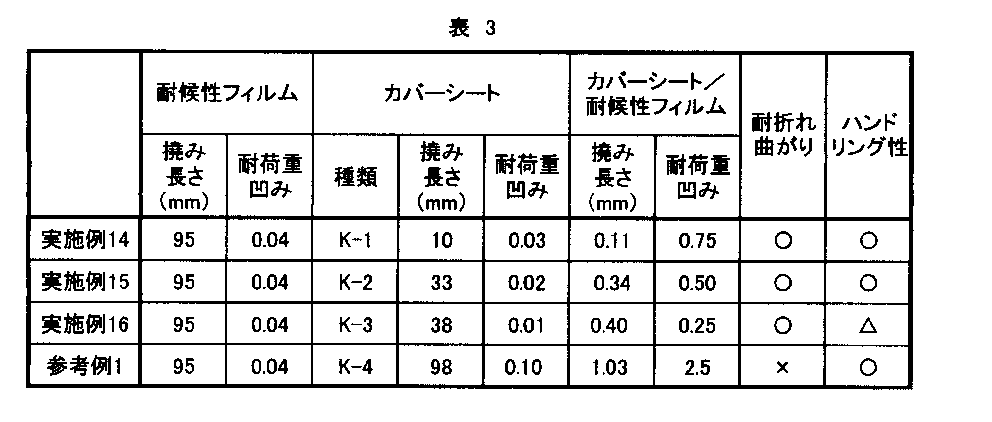
ガラス、封止材と、実施例17、18及び比較例1の保護シート(E-16、E-17、E-13)を、耐候性フィルムが暴露側になるように順に積層し、真空ラミネーター(エヌ・ピー・シー社製、LM30×30)を用いて、温度150℃、脱気時間5分、プレス圧力0.1MPa、プレス時間10分の条件で真空ラミネーションを行い、状態を観察し、下記の基準で評価した。
(○):気泡が全くない状態
(×):気泡が1個以上確認される状態 (10) Foamed glass, sealing material, and protective sheets of Examples 17 and 18 and Comparative Example 1 (E-16, E-17, E-13) are laminated in order so that the weather-resistant film is on the exposed side Then, using a vacuum laminator (NPC, LM30 × 30), vacuum lamination was performed under conditions of a temperature of 150 ° C., a degassing time of 5 minutes, a press pressure of 0.1 MPa, and a press time of 10 minutes. Were observed and evaluated according to the following criteria.
(○): No bubbles at all (×): One or more bubbles are confirmed
厚み38μmのシリコーン離型PETフィルム1(中本パックス社製、NS-38+A、融点262℃、幅340mm)に粘着剤を厚みが20μmとなるよう塗布し、乾燥して粘着剤層(接着剤層1)を形成し、粘着シート1を作製した。一方、厚み38μmのシリコーン離型PETフィルム2(中本パックス社製、NS-38+A、融点262℃、幅340mm)に粘着剤を厚みが20μmとなるよう塗布し、乾燥して粘着剤層(接着剤層2)を形成し、粘着シート2を作製した。
次いで、防湿フィルムB-1(幅340mm)のSiOx側の面に粘着シート1を貼り合わせ、他方の面に粘着シート2を貼り合わせ、積層体Xを得た。
次いで、積層体Xの幅方向の両端を6mmずつスリットして、積層体X’(幅WX':328mm)を得た。
次いで、積層体X’の離型シートを剥離して、接着剤層1に耐候性フィルムA-1(幅380mm)を貼り合わせ、接着剤層2にフィルムC-3(幅330mm)を貼り合わせ、40℃で4日間養生し、耐候性フィルム(A-1)-接着剤層1-防湿フィルム(B-1)-接着剤層2-フィルムC-3の構成からなる保護シートE-16を得た。 Example 17
A pressure-sensitive adhesive was applied to a 38 μm-thick silicone release PET film 1 (manufactured by Nakamoto Pax, NS-38 + A, melting point 262 ° C., width 340 mm) to a thickness of 20 μm and dried to form a pressure-sensitive adhesive layer (adhesive layer) 1) was formed, and the
Next, the pressure-
Next, both ends in the width direction of the laminate X were slit by 6 mm to obtain a laminate X ′ (width W X ′ : 328 mm).
Next, the release sheet of the laminate X ′ is peeled off, the weather resistant film A-1 (width 380 mm) is bonded to the
積層体Xの両端のスリット幅を10mmに変更した以外は実施例17同様に、実施例18の保護シート(E-17)を得た。なお、実施例18の製造過程の積層体X’の幅WX'は320mmである。 Example 18
A protective sheet (E-17) of Example 18 was obtained in the same manner as in Example 17 except that the slit width at both ends of the laminate X was changed to 10 mm. Note that the width W X ′ of the stacked body X ′ in the manufacturing process of Example 18 is 320 mm.
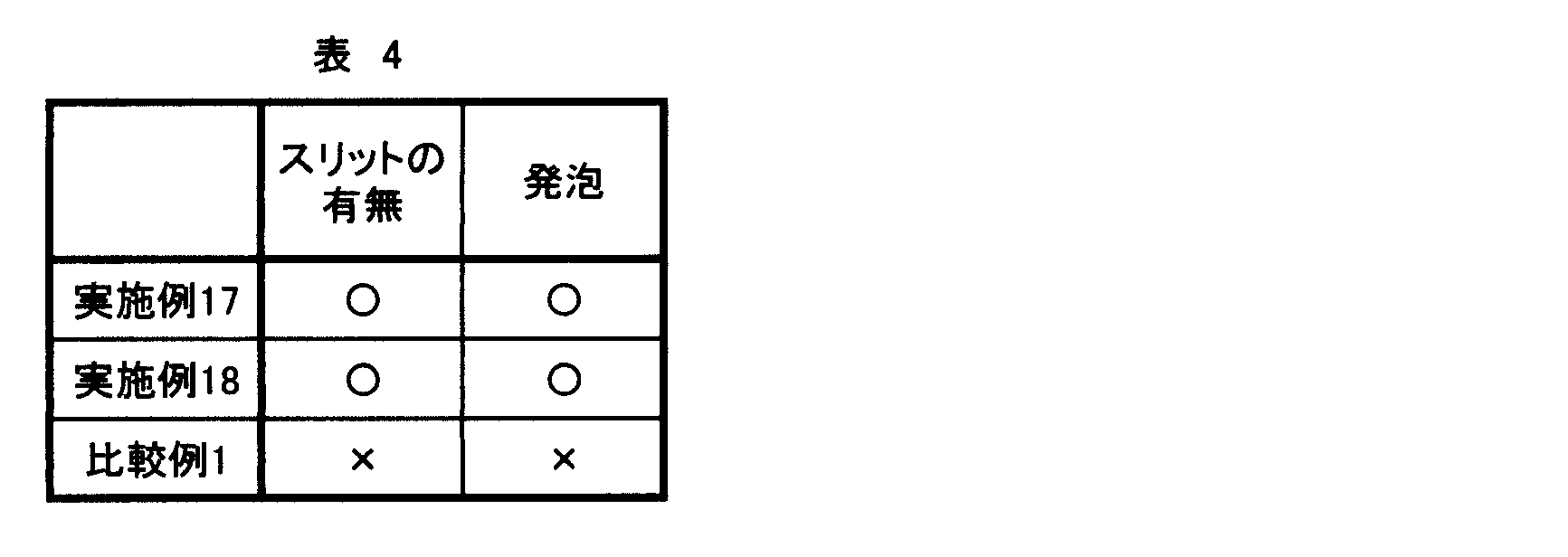
21、22:接着剤層
3:フィルムB
4:フィルムC
51、52:離型シート
6:スリッター
10:保護シート
11:突出部
20:封止材
30:電子デバイス 1: Weather
4: Film C
51, 52: Release sheet 6: Slitter 10: Protection sheet 11: Protruding part 20: Sealing material 30: Electronic device
Claims (19)
- 少なくとも、耐候性フィルムA、接着剤層1、フィルムB、接着剤層2、及び厚みが60μm以上であるフィルムCをこの順に有する保護シートであって、前記耐候性フィルムの幅WA、フィルムBの幅WB、及びフィルムCの幅WCが、WA>WC>WBの関係を有する保護シート。 A protective sheet having at least a weather-resistant film A, an adhesive layer 1, a film B, an adhesive layer 2, and a film C having a thickness of 60 μm or more in this order, the width W A of the weather-resistant film, the film B The width W B of the film and the width W C of the film C have a relationship of W A > W C > W B.
- 幅WCに対する幅WBの比(WB/WC)が0.65以上、1.0未満であり、かつ幅WCと幅WBの差(WC-WB)が32mm以下である、請求項1に記載の保護シート。 The ratio of the width W B to the width W C (W B / W C ) is 0.65 or more and less than 1.0, and the difference (W C −W B ) between the width W C and the width W B is 32 mm or less. The protective sheet according to claim 1.
- 幅WAに対する幅WCの比(WC/WA)が0.70以上、1.0未満であり、かつ幅WAと幅WCの差(WA-WC)が80mm以下である、請求項1又は2に記載の保護シート。 The ratio of the width W C to the width W A (W C / W A ) is 0.70 or more and less than 1.0, and the difference between the width W A and the width W C (W A −W C ) is 80 mm or less. The protective sheet according to claim 1 or 2, wherein
- フィルムCの厚みに対する耐候性フィルムAの厚みの比(耐候性フィルムAの厚み/フィルムCの厚み)が0.75以下である、請求項1~3のいずれかに記載の保護シート。 The protective sheet according to any one of claims 1 to 3, wherein the ratio of the thickness of the weather resistant film A to the thickness of the film C (the thickness of the weather resistant film A / the thickness of the film C) is 0.75 or less.
- フィルムCの、23℃における引張弾性率が2.0GPa以上である、請求項1~4のいずれかに記載の保護シート。 The protective sheet according to any one of claims 1 to 4, wherein the film C has a tensile elastic modulus at 23 ° C of 2.0 GPa or more.
- フィルムBが、基材及び該基材の少なくとも一方の面に無機層を有し、水蒸気透過率が0.1g/m2/day未満の防湿フィルムである、請求項1~5のいずれかに記載の保護シート。 The film B is a moisture-proof film having a substrate and an inorganic layer on at least one surface of the substrate and having a water vapor transmission rate of less than 0.1 g / m 2 / day. The protective sheet described.
- 前記防湿フィルムを、前記無機層側の面を前記耐候性フィルムA側にして積層してなる、請求項6に記載の保護シート。 The protective sheet according to claim 6, wherein the moisture-proof film is laminated with the surface on the inorganic layer side facing the weather-resistant film A side.
- 接着剤層1及び/又は接着剤層2が粘着剤を含む、請求項1~7のいずれかに記載の保護シート。 The protective sheet according to any one of claims 1 to 7, wherein the adhesive layer 1 and / or the adhesive layer 2 contains an adhesive.
- 耐候性フィルムAの熱収縮率が0.5%以上である、請求項1~8のいずれかに記載の保護シート。 The protective sheet according to any one of claims 1 to 8, wherein the heat-shrink rate of the weather resistant film A is 0.5% or more.
- 太陽電池用として用いる、請求項1~9のいずれかに記載の保護シート。 The protective sheet according to any one of claims 1 to 9, which is used for solar cells.
- 請求項1~10のいずれかに記載の保護シートのフィルムC側に、さらに封止材層Dが積層されてなる、封止材一体型保護シート。 A sealing material-integrated protective sheet, in which a sealing material layer D is further laminated on the film C side of the protective sheet according to any one of claims 1 to 10.
- 前記封止材層の幅WDが、前記耐候性フィルムの幅WAより小さく、かつ前記フィルムCの幅WCより大きい、請求項11に記載の封止材一体型保護シート。 12. The encapsulant-integrated protective sheet according to claim 11, wherein a width W D of the encapsulant layer is smaller than a width W A of the weather resistant film and greater than a width W C of the film C.
- 請求項1~10のいずれかに記載の保護シート又は請求項11及び12のいずれかに記載の封止材一体型保護シートが巻き取られてなる、ロール状物。 A roll-shaped product obtained by winding the protective sheet according to any one of claims 1 to 10 or the protective sheet-integrated protective sheet according to any one of claims 11 and 12.
- 請求項13に記載のロール状物の表面のうち、耐候性フィルムAが突出する箇所に対応する箇所の少なくとも一部を、以下の条件により測定される撓み長さが70mm以下であり、かつ耐荷重凹みが0.1以下であるカバーシートで覆ってなる、カバーシート付きロール状物。
[撓み長さ]
(1)幅20mm、長さ120mmのサンプルを採取する。
(2)サンプルを台上に、サンプルのうち長さ100mmの部分が台から突出するようにして配置し、サンプルの台上の部分に、重さ5kgの重りを乗せてサンプルを固定する。
(3)サンプルの台から突出する部分の端部が、台から垂れ下がる長さ「x」(単位:mm)を測定し、この値を撓み長さとする。
[耐荷重凹み]
(1)100mm四方のサンプルを採取する。
(2)サンプルを厚さ20mmのガラス板上に設置し、サンプルの中央部に直径5mmで重さ0.5gの鋼球を載せ、さらに鋼球上から2kgの荷重をかける。
(3)サンプルの凹み「d」(単位:μm)を測定し、サンプルの厚み「t」(単位:μm)との比「d/t」を耐荷重凹みとする。 Of the surface of the roll-shaped product according to claim 13, at least a part of the part corresponding to the part from which the weather resistant film A protrudes has a deflection length of 70 mm or less measured under the following conditions, and A roll with cover sheet, which is covered with a cover sheet having a load dent of 0.1 or less.
[Bending length]
(1) A sample having a width of 20 mm and a length of 120 mm is taken.
(2) Place the sample on the table so that a 100 mm long portion of the sample protrudes from the table, and fix the sample by placing a weight of 5 kg on the sample.
(3) The length “x” (unit: mm) at which the end of the portion protruding from the sample hangs down from the pedestal is measured, and this value is taken as the bending length.
[Load dent]
(1) Collect a 100 mm square sample.
(2) A sample is placed on a glass plate having a thickness of 20 mm, a steel ball having a diameter of 5 mm and a weight of 0.5 g is placed on the center of the sample, and a load of 2 kg is further applied on the steel ball.
(3) The dent “d” (unit: μm) of the sample is measured, and the ratio “d / t” to the thickness “t” (unit: μm) of the sample is defined as a load-bearing dent. - 以下(a’)及び/又は(b’)の条件を満たす、請求項14に記載のカバーシート付きロール状物。
(a’)[カバーシートの撓み長さ]/[耐候性フィルムAの撓み長さ]が2以下
(b’)[カバーシートの耐荷重凹み]/[耐候性フィルムAの耐荷重凹み]が2以下 The roll-like article with a cover sheet according to claim 14, which satisfies the following conditions (a ′) and / or (b ′).
(A ′) [Bend length of cover sheet] / [Bend length of weather resistant film A] is 2 or less (b ′) [Load dent of cover sheet] / [Load dent of weather resistant film A] 2 or less - 以下の(1)~(4)の工程を有する、保護シートの製造方法。
(1)フィルムBの一方の面に接着剤層1を有し、他方の面に接着剤層2を有する積層体Xを作製する工程
(2)積層体Xの幅方向の両端をスリットし、積層体X’とする工程
(3)接着剤層1上に、積層体X’の幅WX'よりも広い幅WAを有する耐候性フィルムAを、耐候性フィルムAの両端が接着剤層1の両端から突出するようにして貼り合わせる工程
(4)接着剤層2上に、積層体X’の幅WX'よりも広く、耐候性フィルムAの幅WAよりも狭い幅WCを有するフィルムCを、フィルムCの両端が接着剤層2の両端から突出するようにして貼り合わせる工程 A method for producing a protective sheet, comprising the following steps (1) to (4):
(1) Step of producing a laminate X having the adhesive layer 1 on one surface of the film B and the adhesive layer 2 on the other surface (2) slitting both ends in the width direction of the laminate X, Step (3) for forming laminated body X ′ A weather resistant film A having a width W A wider than the width W X ′ of the laminated body X ′ is formed on the adhesive layer 1, and both ends of the weather resistant film A are adhesive layers. (4) On the adhesive layer 2, a width W C wider than the width W X ′ of the laminate X ′ and narrower than the width W A of the weather resistant film A is bonded onto the adhesive layer 2. Bonding the film C having the film C so that both ends of the film C protrude from both ends of the adhesive layer 2 - 前記工程(1)において、積層体Xとして、接着剤層1上に離型シート1を有し、接着剤層2上に離型シート2を有するものを作製し、前記工程(2)の後であって工程(3)の前に離型シート1を剥離し、前記工程(2)の後であって工程(4)の前に離型シート2を剥離する工程を経る、請求項16に記載の保護シートの製造方法。 In the step (1), a laminate X having the release sheet 1 on the adhesive layer 1 and the release sheet 2 on the adhesive layer 2 is prepared, and after the step (2) In the step 16, the release sheet 1 is peeled off before the step (3), and the release sheet 2 is peeled off after the step (2) and before the step (4). The manufacturing method of the protective sheet of description.
- 前記工程(1)が以下の(1-1)~(1-3)の工程を有してなる、請求項17に記載の保護シートの製造方法。
(1-1)離型シート1上に接着剤層1組成物を塗布、乾燥して接着剤層1を形成する工程
(1-2)離型シート2上に接着剤層2組成物を塗布、乾燥して接着剤層2を形成する工程
(1-3)フィルムBに、接着剤層1及び接着剤層2を貼り合わせ、積層体Xとする工程 The method for producing a protective sheet according to claim 17, wherein the step (1) includes the following steps (1-1) to (1-3).
(1-1) Step of applying adhesive layer 1 composition on release sheet 1 and drying to form adhesive layer 1 (1-2) Applying adhesive layer 2 composition on release sheet 2 Step of drying to form the adhesive layer 2 (1-3) Step of bonding the adhesive layer 1 and the adhesive layer 2 to the film B to form the laminate X - 請求項1~10のいずれかに記載の保護シート又は請求項11及び12のいずれかに記載の封止材一体型保護シートを用いて作製された太陽電池モジュール。 A solar cell module produced using the protective sheet according to any one of claims 1 to 10 or the protective sheet-integrated protective sheet according to any one of claims 11 and 12.
Priority Applications (4)
| Application Number | Priority Date | Filing Date | Title |
|---|---|---|---|
| KR1020147017649A KR20140113659A (en) | 2011-12-28 | 2012-12-27 | Protective sheet |
| US14/369,053 US20140373914A1 (en) | 2011-12-28 | 2012-12-27 | Protective sheet |
| CN201280064767.XA CN104025314B (en) | 2011-12-28 | 2012-12-27 | Screening glass |
| EP12861108.4A EP2800148B1 (en) | 2011-12-28 | 2012-12-27 | Protective sheet |
Applications Claiming Priority (8)
| Application Number | Priority Date | Filing Date | Title |
|---|---|---|---|
| JP2011290036A JP5449312B2 (en) | 2011-12-28 | 2011-12-28 | Protective material for solar cells |
| JP2011-290036 | 2011-12-28 | ||
| JP2012071862A JP5474116B2 (en) | 2012-03-27 | 2012-03-27 | Protection sheet for solar cell |
| JP2012-071862 | 2012-03-27 | ||
| JP2012-272839 | 2012-12-13 | ||
| JP2012272837A JP5400948B1 (en) | 2012-12-13 | 2012-12-13 | ROLLED PRODUCT WITH COVER SHEET AND METHOD FOR PRODUCING ROLLED PRODUCT WITH COVER SHEET |
| JP2012272839A JP2014117831A (en) | 2012-12-13 | 2012-12-13 | Method for producing laminate |
| JP2012-272837 | 2012-12-13 |
Publications (1)
| Publication Number | Publication Date |
|---|---|
| WO2013100109A1 true WO2013100109A1 (en) | 2013-07-04 |
Family
ID=48697587
Family Applications (1)
| Application Number | Title | Priority Date | Filing Date |
|---|---|---|---|
| PCT/JP2012/083998 WO2013100109A1 (en) | 2011-12-28 | 2012-12-27 | Protective sheet |
Country Status (6)
| Country | Link |
|---|---|
| US (1) | US20140373914A1 (en) |
| EP (1) | EP2800148B1 (en) |
| KR (1) | KR20140113659A (en) |
| CN (1) | CN104025314B (en) |
| TW (1) | TW201332763A (en) |
| WO (1) | WO2013100109A1 (en) |
Cited By (1)
| Publication number | Priority date | Publication date | Assignee | Title |
|---|---|---|---|---|
| JP2015146360A (en) * | 2014-01-31 | 2015-08-13 | 富士フイルム株式会社 | Protective sheet for solar cell, back sheet for solar cell, solar cell module, and method for re-processing solar cell module |
Families Citing this family (9)
| Publication number | Priority date | Publication date | Assignee | Title |
|---|---|---|---|---|
| WO2015133631A1 (en) * | 2014-03-07 | 2015-09-11 | 旭硝子株式会社 | Method for producing semiconductor-element-mounting package, and mould-release film |
| TWI544652B (en) * | 2015-01-19 | 2016-08-01 | 台虹科技股份有限公司 | Solar cell back sheet |
| JPWO2017090240A1 (en) * | 2015-11-25 | 2018-11-01 | パナソニックIpマネジメント株式会社 | Vacuum heat insulating body, heat insulating container using the same, heat insulating wall and refrigerator |
| KR101943701B1 (en) * | 2016-04-25 | 2019-01-29 | 삼성에스디아이 주식회사 | Polarizer protection film and polarizer plate comprising the same and liquid crystal display comprising the polarizer plate |
| KR102108566B1 (en) * | 2017-09-25 | 2020-05-08 | 주식회사 엘지화학 | Encapsulation film |
| CN114174059A (en) * | 2019-07-17 | 2022-03-11 | 惠和株式会社 | Structure protection sheet, construction method using the same, prefabricated part, and method for manufacturing prefabricated part |
| US11695089B2 (en) * | 2019-12-31 | 2023-07-04 | Industrial Technology Research Institute | Solar cell modules |
| CN113027042A (en) * | 2021-03-25 | 2021-06-25 | 武汉美格科技股份有限公司 | Photovoltaic tile preparation method and photovoltaic tile |
| CN115394866B (en) * | 2022-08-24 | 2023-03-10 | 武汉美格科技股份有限公司 | Method for eliminating surface wrinkles of flexible assembly and assembly |
Citations (5)
| Publication number | Priority date | Publication date | Assignee | Title |
|---|---|---|---|---|
| JPH0685300A (en) * | 1992-09-01 | 1994-03-25 | Canon Inc | Solar cell module |
| JPH07142756A (en) * | 1993-06-24 | 1995-06-02 | Canon Inc | Solar battery module and its manufacture |
| JP2009051207A (en) | 2007-07-31 | 2009-03-12 | Techno Polymer Co Ltd | Layered product |
| JP2010232233A (en) | 2009-03-26 | 2010-10-14 | Lintec Corp | Protective sheet for solar cell module, method for manufacturing the same, and solar cell module |
| WO2010150692A1 (en) * | 2009-06-23 | 2010-12-29 | 東レエンジニアリング株式会社 | Solar battery |
Family Cites Families (6)
| Publication number | Priority date | Publication date | Assignee | Title |
|---|---|---|---|---|
| ES2391842T3 (en) * | 2000-07-03 | 2012-11-30 | Bridgestone Corporation | Coating material of the rear face of a solar cell module and its use |
| JP5237569B2 (en) * | 2007-02-27 | 2013-07-17 | 東洋アルミニウム株式会社 | Solar cell back surface protection sheet and solar cell module including the same |
| US20100252101A1 (en) * | 2007-11-16 | 2010-10-07 | Okura Industrial Co. Ltd | Back protective sheet for solar cell module and solar cell module protected thereby |
| JP2009188072A (en) * | 2008-02-05 | 2009-08-20 | Toppan Printing Co Ltd | Layered product and rear surface protective sheet for solar cell |
| US7960643B2 (en) * | 2009-05-12 | 2011-06-14 | Miasole | Isolated metallic flexible back sheet for solar module encapsulation |
| EP2580790A4 (en) * | 2010-06-08 | 2015-11-25 | Amerasia Int Technology Inc | Solar cell interconnection, module, panel and method |
-
2012
- 2012-12-27 EP EP12861108.4A patent/EP2800148B1/en not_active Not-in-force
- 2012-12-27 US US14/369,053 patent/US20140373914A1/en not_active Abandoned
- 2012-12-27 KR KR1020147017649A patent/KR20140113659A/en not_active Application Discontinuation
- 2012-12-27 WO PCT/JP2012/083998 patent/WO2013100109A1/en active Application Filing
- 2012-12-27 CN CN201280064767.XA patent/CN104025314B/en not_active Expired - Fee Related
- 2012-12-28 TW TW101151329A patent/TW201332763A/en unknown
Patent Citations (5)
| Publication number | Priority date | Publication date | Assignee | Title |
|---|---|---|---|---|
| JPH0685300A (en) * | 1992-09-01 | 1994-03-25 | Canon Inc | Solar cell module |
| JPH07142756A (en) * | 1993-06-24 | 1995-06-02 | Canon Inc | Solar battery module and its manufacture |
| JP2009051207A (en) | 2007-07-31 | 2009-03-12 | Techno Polymer Co Ltd | Layered product |
| JP2010232233A (en) | 2009-03-26 | 2010-10-14 | Lintec Corp | Protective sheet for solar cell module, method for manufacturing the same, and solar cell module |
| WO2010150692A1 (en) * | 2009-06-23 | 2010-12-29 | 東レエンジニアリング株式会社 | Solar battery |
Non-Patent Citations (1)
| Title |
|---|
| See also references of EP2800148A4 |
Cited By (1)
| Publication number | Priority date | Publication date | Assignee | Title |
|---|---|---|---|---|
| JP2015146360A (en) * | 2014-01-31 | 2015-08-13 | 富士フイルム株式会社 | Protective sheet for solar cell, back sheet for solar cell, solar cell module, and method for re-processing solar cell module |
Also Published As
| Publication number | Publication date |
|---|---|
| CN104025314B (en) | 2016-08-17 |
| EP2800148A4 (en) | 2015-09-30 |
| CN104025314A (en) | 2014-09-03 |
| US20140373914A1 (en) | 2014-12-25 |
| TW201332763A (en) | 2013-08-16 |
| EP2800148A1 (en) | 2014-11-05 |
| KR20140113659A (en) | 2014-09-24 |
| EP2800148B1 (en) | 2018-04-04 |
Similar Documents
| Publication | Publication Date | Title |
|---|---|---|
| WO2013100109A1 (en) | Protective sheet | |
| JP5769723B2 (en) | Protective sheet for solar cell, method for producing the same, and solar cell module | |
| WO2013118570A1 (en) | Protective sheet for solar cell, and solar cell module | |
| JP2010165873A (en) | Rear surface protective sheet and solar battery module using the same | |
| WO2013100108A1 (en) | Protective material for solar cells | |
| JP2007253463A (en) | Surface protective sheet for solar cell module | |
| WO2013121838A1 (en) | Protective sheet for solar cell, method for manufacturing same, and solar cell module | |
| JP2014041900A (en) | Solar battery protective material and solar battery | |
| WO2014156518A1 (en) | Solar cell module production method | |
| JP5474116B2 (en) | Protection sheet for solar cell | |
| JP6456668B2 (en) | Solar cell back surface protection sheet and solar cell module | |
| JP6305082B2 (en) | Protective sheet for solar cell, back sheet for solar cell, solar cell module and method for reworking solar cell module | |
| JP2011204880A (en) | Protective sheet for solar cell module and the solar cell module | |
| JP5474171B1 (en) | Protective material for solar cells | |
| WO2014208759A1 (en) | Solar cell protective material | |
| WO2014208758A1 (en) | Protective material for solar cell | |
| JP5400948B1 (en) | ROLLED PRODUCT WITH COVER SHEET AND METHOD FOR PRODUCING ROLLED PRODUCT WITH COVER SHEET | |
| JP6021501B2 (en) | Manufacturing method of laminate | |
| JP5449312B2 (en) | Protective material for solar cells | |
| JP2013201341A (en) | Surface protective sheet for solar cell module and solar cell module | |
| JP2013084929A (en) | Solar battery protective material | |
| WO2015068849A1 (en) | Solar cell rear surface protective sheet | |
| JP2014117831A (en) | Method for producing laminate | |
| JP5696172B2 (en) | Protective sheet for solar cell, method for producing the same, and solar cell module | |
| JP2013084928A (en) | Solar battery protective material |
Legal Events
| Date | Code | Title | Description |
|---|---|---|---|
| 121 | Ep: the epo has been informed by wipo that ep was designated in this application |
Ref document number: 12861108 Country of ref document: EP Kind code of ref document: A1 |
|
| WWE | Wipo information: entry into national phase |
Ref document number: 2012861108 Country of ref document: EP |
|
| ENP | Entry into the national phase |
Ref document number: 20147017649 Country of ref document: KR Kind code of ref document: A |
|
| WWE | Wipo information: entry into national phase |
Ref document number: 14369053 Country of ref document: US |
|
| NENP | Non-entry into the national phase |
Ref country code: DE |