WO2013094026A1 - 磁気軸受装置 - Google Patents
磁気軸受装置 Download PDFInfo
- Publication number
- WO2013094026A1 WO2013094026A1 PCT/JP2011/079542 JP2011079542W WO2013094026A1 WO 2013094026 A1 WO2013094026 A1 WO 2013094026A1 JP 2011079542 W JP2011079542 W JP 2011079542W WO 2013094026 A1 WO2013094026 A1 WO 2013094026A1
- Authority
- WO
- WIPO (PCT)
- Prior art keywords
- sensor
- magnetic bearing
- rotating shaft
- sensor holding
- bearing device
- Prior art date
- Legal status (The legal status is an assumption and is not a legal conclusion. Google has not performed a legal analysis and makes no representation as to the accuracy of the status listed.)
- Ceased
Links
Images




Classifications
-
- F—MECHANICAL ENGINEERING; LIGHTING; HEATING; WEAPONS; BLASTING
- F16—ENGINEERING ELEMENTS AND UNITS; GENERAL MEASURES FOR PRODUCING AND MAINTAINING EFFECTIVE FUNCTIONING OF MACHINES OR INSTALLATIONS; THERMAL INSULATION IN GENERAL
- F16C—SHAFTS; FLEXIBLE SHAFTS; ELEMENTS OR CRANKSHAFT MECHANISMS; ROTARY BODIES OTHER THAN GEARING ELEMENTS; BEARINGS
- F16C32/00—Bearings not otherwise provided for
- F16C32/04—Bearings not otherwise provided for using magnetic or electric supporting means
- F16C32/0406—Magnetic bearings
- F16C32/044—Active magnetic bearings
- F16C32/0474—Active magnetic bearings for rotary movement
- F16C32/048—Active magnetic bearings for rotary movement with active support of two degrees of freedom, e.g. radial magnetic bearings
-
- F—MECHANICAL ENGINEERING; LIGHTING; HEATING; WEAPONS; BLASTING
- F16—ENGINEERING ELEMENTS AND UNITS; GENERAL MEASURES FOR PRODUCING AND MAINTAINING EFFECTIVE FUNCTIONING OF MACHINES OR INSTALLATIONS; THERMAL INSULATION IN GENERAL
- F16C—SHAFTS; FLEXIBLE SHAFTS; ELEMENTS OR CRANKSHAFT MECHANISMS; ROTARY BODIES OTHER THAN GEARING ELEMENTS; BEARINGS
- F16C32/00—Bearings not otherwise provided for
- F16C32/04—Bearings not otherwise provided for using magnetic or electric supporting means
- F16C32/0406—Magnetic bearings
- F16C32/044—Active magnetic bearings
- F16C32/0444—Details of devices to control the actuation of the electromagnets
- F16C32/0446—Determination of the actual position of the moving member, e.g. details of sensors
-
- F—MECHANICAL ENGINEERING; LIGHTING; HEATING; WEAPONS; BLASTING
- F16—ENGINEERING ELEMENTS AND UNITS; GENERAL MEASURES FOR PRODUCING AND MAINTAINING EFFECTIVE FUNCTIONING OF MACHINES OR INSTALLATIONS; THERMAL INSULATION IN GENERAL
- F16C—SHAFTS; FLEXIBLE SHAFTS; ELEMENTS OR CRANKSHAFT MECHANISMS; ROTARY BODIES OTHER THAN GEARING ELEMENTS; BEARINGS
- F16C32/00—Bearings not otherwise provided for
- F16C32/04—Bearings not otherwise provided for using magnetic or electric supporting means
- F16C32/0406—Magnetic bearings
- F16C32/044—Active magnetic bearings
- F16C32/0459—Details of the magnetic circuit
- F16C32/0461—Details of the magnetic circuit of stationary parts of the magnetic circuit
-
- F—MECHANICAL ENGINEERING; LIGHTING; HEATING; WEAPONS; BLASTING
- F16—ENGINEERING ELEMENTS AND UNITS; GENERAL MEASURES FOR PRODUCING AND MAINTAINING EFFECTIVE FUNCTIONING OF MACHINES OR INSTALLATIONS; THERMAL INSULATION IN GENERAL
- F16C—SHAFTS; FLEXIBLE SHAFTS; ELEMENTS OR CRANKSHAFT MECHANISMS; ROTARY BODIES OTHER THAN GEARING ELEMENTS; BEARINGS
- F16C32/00—Bearings not otherwise provided for
- F16C32/04—Bearings not otherwise provided for using magnetic or electric supporting means
- F16C32/0406—Magnetic bearings
- F16C32/044—Active magnetic bearings
- F16C32/0474—Active magnetic bearings for rotary movement
- F16C32/0487—Active magnetic bearings for rotary movement with active support of four degrees of freedom
Definitions
- the present invention relates to a magnetic bearing device, and more particularly to a magnetic bearing device provided with a sensor for detecting the position of a rotating shaft portion.
- a magnetic bearing device having a sensor for detecting the position of a rotating shaft portion is known.
- Such a magnetic bearing device is disclosed in, for example, Japanese Patent Laid-Open No. 62-233518.
- the position of the rotating shaft is detected by detecting the electromagnet that supports the rotating shaft in a non-contact manner in the radial direction by magnetic attraction and the radial distance to the rotating shaft.
- a magnetic bearing device including a displacement sensor is disclosed. In this magnetic bearing device, the displacement sensor is disposed at a position shifted in the axial direction with respect to the electromagnet.
- the displacement sensor is disposed at a position shifted in the axial direction with respect to the electromagnet, so that the radial direction between the electromagnet and the rotating shaft is arranged. It is difficult to accurately detect the distance. For this reason, there is a problem that it is difficult to accurately detect the position of the portion (the portion facing the electromagnet) where the magnetic attractive force of the rotating shaft is working.
- the present invention has been made to solve the above-described problems, and one object of the present invention is to accurately detect the position of the portion of the rotating shaft where the magnetic attractive force is acting. Is to provide a magnetic bearing device.
- a magnetic bearing device includes an electromagnet core and a coil, and detects a position of the rotating shaft portion, an electromagnet that supports the rotating shaft portion in a non-contact manner by a magnetic attractive force.
- the sensor is arranged at a portion facing the rotating shaft portion of the electromagnet core.
- the senor is arranged at a portion facing the rotating shaft portion of the electromagnet core.
- the sensor can be arranged at a position facing the portion where the magnetic attraction force of the rotating shaft portion is working (the portion facing the electromagnet core). The position can be detected accurately.
- FIG. 3 is a cross-sectional view taken along line 100-100 in FIG.
- FIG. 3 is a cross-sectional view taken along line 200-200 in FIG. It is the disassembled perspective view which expanded and showed the electromagnet core, sensor holding part, and sensor by one Embodiment of this invention.
- 1 is a block diagram illustrating an overall configuration of a magnetic bearing device according to an embodiment of the present invention. It is the figure which showed the whole structure of the magnetic bearing apparatus by the modification of one Embodiment of this invention.
- a pair of magnetic bearing devices 10 are provided on both sides in the axial direction (axial direction: direction in which the rotation shaft 21 extends) of the motor 20 having the rotation shaft 21.
- Each of the pair of magnetic bearing devices 10 is a straight line extending radially from the rotation center O (see FIG. 2) of the rotation shaft 21 in the radial direction (radial direction: plane orthogonal to the rotation shaft 21) with respect to the rotation shaft 21.
- a predetermined space (a gap 30 having a gap length L1 (see FIG. 3)) is disposed in the direction along the direction.
- the rotating shaft 21 is an example of the “rotating shaft portion” in the present invention.
- the magnetic bearing device 10 is wound around an electromagnet core 12 composed of a plurality of electromagnetic steel plates (see FIGS. 1 and 3 to 5) stacked in the axial direction, and a columnar portion 12b (to be described later) of the electromagnet core 12.
- An electromagnet 11 including a coil 13 is provided.
- the electromagnet 11 supports the rotary shaft 21 in a radial direction in a non-contact manner by a magnetic attraction force by generating a magnetic field (refer to a one-dot chain line with an arrow in FIG. 2) in a plane orthogonal to the rotary shaft 21. It is configured.
- the electromagnet core 12 has a circumferential portion 12 a that circumferentially surrounds the outer peripheral surface of the rotating shaft 21, and a columnar shape along the radial direction from the inner peripheral portion of the circumferential portion 12 a to the rotating shaft 21 side. It is comprised so that the four columnar parts 12b extended may be included.
- the circumferential portion 12a has a cylindrical shape extending along the axial direction.
- the four columnar portions 12b are provided one on each side of the rotating shaft 21 in the vertical direction (X direction) and the horizontal direction (Y direction).
- first columnar portions 12b that face in the vertical direction via the rotation shaft 21 and the pair of columnar portions 12b that face in the left-right direction via the rotation shaft 21 are referred to as “first columnar portions” and “ It is an example of a “second columnar portion”.
- the sensor holding portion 15 is provided on the portion of the electromagnet core 12 that faces the rotation shaft 21 (that is, the end surface of the columnar portion 12 b on the rotation shaft 21 side).
- the sensor 14 held in the position is arranged.
- each of the four columnar portions 12b is provided with a through hole 12c that penetrates the electromagnet core 12 from the inner peripheral side to the outer peripheral side.
- the sensor 14 held by the sensor holding unit 15 is inserted and embedded.
- the through hole 12c is an example of the “insertion hole” in the present invention.
- the through hole 12c is formed to extend along the radial direction in the vicinity of the central portion inside the columnar portion 12b.
- the sensor 14 is a capacitance type or inductance type gap sensor that electromagnetically detects the position of the rotating shaft 21. That is, the sensor 14 detects an electromagnetic change accompanying a change in the radial gap length L1 (see FIG. 3) of the space (gap 30) between the electromagnet core 12 and the rotary shaft 21, thereby detecting the rotational axis. 21 positions are detected. As shown in FIGS. 2 to 5, the sensor 14 is a rod-shaped sensor having a columnar shape extending along the radial direction.
- the sensor holding portion 15 is formed in a cylindrical shape covering the periphery (outer peripheral surface) of the columnar sensor 14 extending along the radial direction.
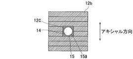
- the sensor holding portion 15 is formed in a cylindrical shape having an inner peripheral surface corresponding to the outer peripheral surface of the columnar sensor 14 extending along the radial direction. That is, as shown in FIG. 4, the sensor holding part 15 has a circular inner peripheral part corresponding to the circular outer peripheral part of the sensor 14 when viewed from the direction in which the sensor 14 and the sensor holding part 15 extend (radial direction).
- the through hole 15a is included.
- the sensor 14 is inserted into the through hole 15a of the cylindrical sensor holding part 15, so that the sensor holding part 15 covers the periphery.
- the sensor 14 is bonded to the inside of the through hole 15a of the cylindrical sensor holding portion 15 with an adhesive.
- the sensor holding portion 15 is made of a nonmagnetic conductor such as aluminum, copper, or brass.
- the sensor holding unit 15 has a shield function that suppresses the electromagnetic influence on the sensor 14 due to the fluctuation of the magnetic field generated from the coil 13 (see the one-dot chain line with the arrow in FIG. 2). is doing. That is, since the sensor holding part 15 is made of a non-magnetic conductor, when the magnetic field generated from the coil 13 fluctuates, the sensor holding part 15 is attached to the sensor holding part 15 by the principle of electromagnetic induction so as to cancel the fluctuation of the magnetic field. Eddy current flows. The fluctuation of the magnetic field generated from the coil 13 is canceled in the sensor holding unit 15 by the induced magnetic field generated due to the eddy current flowing in this way.
- the sensor holding portion 15 has a quadrangular prism-shaped outer shape extending along the radial direction. That is, as shown in FIG. 4, the sensor holding part 15 has a rectangular outer peripheral part when viewed from the direction in which the sensor holding part 15 extends (radial direction).
- the through hole 12c of the electromagnet core 12 has a rectangular inner peripheral portion corresponding to the rectangular outer peripheral portion of the sensor holding portion 15 when viewed from the direction (radial direction) in which the sensor holding portion 15 and the through hole 12c extend. have.
- the sensor holding portion 15 is inserted into the through hole 12c of the electromagnet core 12 with the sensor 14 held in the through hole 15a.
- the sensor holding portion 15 is bonded to the inside of the through hole 12c of the electromagnet core 12 with an adhesive.
- the length L2 of the sensor holding portion 15 in the radial direction is the length of the through hole 12c of the electromagnet core 12 in the radial direction. Is equal to L3.
- the length L4 of the sensor 14 in the radial direction is smaller than the length L2 of the sensor holding unit 15 in the radial direction.
- the magnetic bearing device 10 controls the position of the rotary shaft 21 by controlling the magnetic attractive force of the electromagnet 11 (FIG. 6). See).
- the control unit 16 is connected to the coil 13 of the electromagnet 11 and the sensor 14.
- the control unit 16 detects the position of the rotating shaft 21 (the gap length L1 in the radial direction of the gap 30 between the electromagnet core 12 and the rotating shaft 21 (see FIG. 3)) by the sensor 14 based on the detection result of the coil 13.
- the position of the rotary shaft 21 is adjusted by adjusting the magnetic attraction force of the electromagnet 11 by controlling the current flowing through the magnet.
- the sensor 14 is disposed on the portion of the electromagnet core 12 that faces the rotating shaft 21 (that is, the end surface of the columnar portion 12b on the rotating shaft 21 side). Thereby, since the sensor 14 can be arrange
- the sensor holding unit 15 that holds the sensor 14 in a state of covering the periphery (outer peripheral surface) of the sensor 14 is provided, and the sensor 14 is surrounded by the sensor holding unit 15. Embedded in the columnar portion 12b.
- the sensor holding unit 15 that covers the periphery of the sensor 14 has an electromagnetic influence on the sensor 14 due to fluctuations in the magnetic field generated from the coil 13 (see the one-dot chain line with an arrow in FIG. 2). Since it can suppress, the detection accuracy of the sensor 14 can be improved.
- the senor 14 is configured to electromagnetically detect the position of the rotating shaft 21, and the sensor holding portion 15 is formed of a nonmagnetic conductor such as aluminum, copper, or brass. To do.
- the sensor holding unit 15 made of a nonmagnetic conductor causes an electromagnetic influence on the sensor 14 due to fluctuations in the magnetic field generated from the coil 13 (see the one-dot chain line with an arrow in FIG. 2). Therefore, the detection accuracy of the sensor 14 can be effectively improved.
- the sensor holding unit 15 is formed in a cylindrical shape, and the sensor 14 is held in the cylindrical sensor holding unit 15, thereby holding the sensor 14 by the sensor holding unit 15. .
- the cylindrical sensor holding portion 15 into which the sensor 14 can be inserted can be easily covered so as to surround the periphery (outer peripheral surface) of the sensor 14, so that the magnetic field generated from the coil 13 (the arrow in FIG. 2). It is possible to easily suppress the electromagnetic influence on the sensor 14 due to the fluctuation of the one-dot chain line).
- the sensor 14 and the sensor holding portion 15 are embedded in the vicinity of the central portion inside the columnar portion 12b of the electromagnet core 12.
- the vicinity of the central portion of the portion where the magnetic attraction force of the rotating shaft 21 is acting by the sensor 14 (the portion of the rotating shaft 21 through which the magnetic field generated from the coil 13 (see the one-dot chain line with an arrow in FIG. 2) passes) Therefore, the position of the portion where the magnetic attraction force of the rotating shaft 21 is working can be detected more accurately.
- the sensor 14 is disposed in the vicinity of the central portion of the columnar portion 12b that is not easily affected by the magnetic field generated from the coil 13, the detection accuracy of the sensor 14 can be further improved.
- both the sensor 14 and the sensor holding portion 15 are formed so as to extend along the radial direction, and the length L4 of the sensor 14 in the radial direction (FIG. 3). 5) is made smaller than the length L2 (see FIGS. 3 and 5) of the sensor holding portion 15 in the radial direction. Accordingly, the sensor 14 can be easily held in a state of covering the periphery (outer peripheral surface) of the sensor 14 with the sensor holding portion 15 having a length in the direction along the radial direction larger than that of the sensor 14. it can.
- the sensor holding portion 15 is embedded in the columnar portion 12b by inserting the sensor holding portion 15 into the through hole 12c provided in the columnar portion 12b of the electromagnet core 12. Thereby, the sensor holding part 15 and the sensor 14 hold
- the sensor holding unit 15 is bonded into the through hole 12c of the electromagnet core 12 with an adhesive. Thereby, the sensor holding
- the sensor holding portion 15 is formed so as to extend along the radial direction of the rotating shaft 21, and the through hole 12c of the electromagnet core 12 is formed in the radial direction inside the columnar portion 12b. It is formed so as to extend along. Thereby, the sensor holding part 15 can be easily inserted into the through hole 12 c of the electromagnet core 12.
- the through-hole 12c of the electromagnet core 12 is formed so as to penetrate the electromagnet core 12 from the inner circumference side to the outer circumference side by extending along the radial direction.
- the sensor holding portion 15 is formed so as to have a rectangular outer peripheral portion (see FIG. 4) when viewed from the radial direction, and the sensor holding portion 15 has a rectangular outer peripheral portion.
- the through-hole 12c of the electromagnet core 12 is formed so as to have a corresponding rectangular inner periphery (see FIG. 4).
- the senor 14 is a rod-shaped sensor extending along the radial direction
- the sensor holding portion 15 is formed in a cylindrical shape having an inner peripheral surface corresponding to the outer peripheral surface of the rod-shaped sensor 14. Form.
- the cylindrical sensor holding portion 15 can easily cover the outer surface of the rod-shaped sensor 14 so that the magnetic field generated from the coil 13 (see the one-dot chain line with an arrow in FIG. 2). It is possible to easily suppress the electromagnetic influence on the sensor 14 due to the fluctuation.
- the length L2 (see FIGS. 3 and 5) in the radial direction of the sensor holding portion 15 is set along the radial direction of the through hole 12c of the electromagnet core 12. It is made equal to the direction length L3 (see FIGS. 3 and 5).
- the circumferential portion 12a that circumferentially surrounds the outer peripheral surface of the rotating shaft 21 and the columnar portion 12b that extends from the circumferential portion 12a toward the rotating shaft 21 in a columnar shape are included.
- the electromagnet core 12 is configured, and the sensor 14 and the sensor holding unit 15 are embedded in a portion of the columnar portion 12b facing the rotation shaft 21. This makes it easy to embed the sensor 14 in the columnar portion 12b of the commonly used electromagnet core 12 (electromagnet core 12 configured as an integral part having the circumferential portion 12a and the columnar portion 12b). It is possible to configure the electromagnet core 12 capable of accurately detecting the position of the portion of the rotating shaft 21 where the magnetic attractive force is working.
- four columnar portions 12b are provided along the circumferential direction (the rotation direction of the rotation shaft 21), and the vertical direction (X direction (see FIG. 2) of the four columnar portions 12b is provided. )) And the pair of columnar portions 12b facing in the left-right direction (Y direction (see FIG. 2)), the sensor 14 and the sensor holding portion 15 are embedded. Thereby, the position of the rotating shaft 21 can be detected more accurately by the total of four sensors 14 arranged one by one on both the vertical and horizontal sides of the rotating shaft 21.
- the control unit 16 connected to the coil 13 and the sensor 14 is provided, and the control unit 16 detects the position of the rotating shaft 21 by the sensor 14 held by the sensor holding unit 15. Based on the result, the position of the rotating shaft 21 is controlled by controlling the current flowing through the coil 13. Thereby, based on the exact position of the part where the magnetic attraction force of the rotating shaft 21 detected by the sensor 14 embedded in the electromagnet core 12 is held by the sensor holding unit 15, The position can be accurately controlled.
- a through hole (insertion hole) that penetrates the electromagnet core from the inner periphery side to the outer periphery side is provided in the electromagnet core, and a sensor (a sensor held by the sensor holding portion) is inserted into the through hole.
- a sensor a sensor held by the sensor holding portion
- the sensor may be embedded in the electromagnet core by providing the electromagnet core with an insertion hole that does not penetrate the electromagnet core from the inner circumference side to the outer circumference side, and inserting the sensor into the insertion hole.
- the sensor may be embedded in the electromagnet core by providing a groove in the electromagnet core and fitting the sensor in the groove.
- the senor 14 is attached to the generally used electromagnet core (the electromagnet core 12 comprised as an integral component which has the circumferential part 12a and the columnar part 12b).
- the present invention is not limited to this.
- the sensor 114 may be embedded in the electromagnet core 112 constituted by the four core portions 1120 having a substantially U shape.
- the four core portions 1120 constituting the electromagnet core 112 are arranged so as to sandwich the rotating shaft 21 from both sides in the vertical direction (X direction) and the horizontal direction (Y direction).
- Each of the four core portions 1120 includes a circumferential portion 112a extending along the circumferential direction (the rotational direction of the rotating shaft 21), and a pair of circumferential portions 112a extending from both ends in the circumferential direction to the rotating shaft 21 side.
- maintained in the through hole 115a of the sensor holding part 115 is inserted and embedded in the through hole 112c provided in each of a pair of columnar part 112b.
- the through hole 112c is an example of the “insertion hole” in the present invention.
- a pair of sensors 114 embedded in each of the pair of columnar portions 112 b included in the core portion 1120 disposed on both sides in the vertical direction (X direction) with respect to the rotation shaft 21 By taking the average of the two detection results (gap length L5 of the air gap 31 and gap length L6 of the air gap 32), the position in the vertical direction (X direction) of the rotating shaft 12 is detected.
- the position of the rotating shaft 12 in the left-right direction (Y direction) is detected.
- the four core portions 1120 having a substantially U-shape in which the rotating shaft 21 is disposed so as to be sandwiched from both sides in the vertical direction (X direction) and the horizontal direction (Y direction).
- the electromagnet core 112 is configured.
- a magnetic attraction force can be applied to the rotating shaft 21 in the vertical direction (left and right direction) by the pair of substantially U-shaped core portions 1120 that sandwich the rotating shaft 21 from both sides in the vertical direction (left and right direction). Therefore, it is possible to easily control the magnetic attractive force.
- the present invention is not limited to this.
- a sensor holding portion having an outer shape other than a quadrangular prism shape for example, a cylindrical shape
- the shape of the insertion hole into which the sensor holding part of the electromagnet core is inserted is also changed so as to correspond to the outer shape of the sensor holding part.
- a rod-shaped sensor having a cylindrical shape (see FIG. 5) is used as the sensor 14, but the present invention is not limited thereto.
- a rod-shaped sensor having a shape other than the columnar shape (for example, a quadrangular prism shape) may be used, or a sensor other than the rod-shaped sensor (for example, a plate sensor) may be used.
- the outer shape of the sensor is changed as described above, it is preferable that the shape of the sensor holding portion that covers the periphery of the sensor is also changed so as to correspond to the outer shape of the sensor.
- maintenance part 15 is the direction along the radial direction of the through-hole 12c (insertion hole) of the electromagnet core 12.
- the length L3 may be smaller than the length of the insertion hole in the radial direction.
- the length L4 (see FIGS. 3 and 5) of the sensor 14 in the radial direction is set to the length L2 (see FIGS. 3 and 5) of the sensor holding portion 15 in the radial direction.
- the present invention is not limited to this.
- the length of the sensor along the radial direction may be equal to the length of the sensor holding portion along the radial direction.
- the present invention is not limited to this.
- the sensor holding portion may be fixed in the insertion hole without using an adhesive.
- the sensor holding part may be fixed in the insertion hole.
- a male screw is formed on the outer peripheral surface of the sensor
- a female screw is formed on the inner peripheral surface of the cylindrical sensor holding portion
- the outer peripheral surface of the sensor and the inner peripheral surface of the cylindrical sensor holding portion are connected. You may fix a sensor in a cylindrical sensor holding
- the present invention is not limited to this.
- One sensor 14 may be embedded in each of the portions 12b. If comprised in this way, while the position of the up-down direction of the rotating shaft 21 can be detected with one sensor 14 embedded in one of a pair of columnar parts 12b opposed to the up-down direction, The position of the rotating shaft 21 in the left-right direction can be detected by one sensor 14 embedded in one of the pair of opposing columnar portions 12b. Accordingly, the positions of the rotary shaft 21 in the vertical direction and the horizontal direction can be detected by the two sensors 14 without embedding the sensors 14 in all of the four columnar portions 12b, thereby reducing the number of parts. Can do.
- the present invention provides an axial magnetic bearing that supports the rotating shaft in the axial direction in a non-contact manner. It can also be applied to bearings.
Landscapes
- Engineering & Computer Science (AREA)
- General Engineering & Computer Science (AREA)
- Mechanical Engineering (AREA)
- Physics & Mathematics (AREA)
- Electromagnetism (AREA)
- Magnetic Bearings And Hydrostatic Bearings (AREA)
Abstract
この磁気軸受装置(10)は、電磁石コア(12、112)およびコイル(13)を含み、磁気吸引力により回転軸部分(21)を非接触で支持する電磁石(11)と、回転軸部分の位置を検出するセンサ(14、114)とを備え、センサは、電磁石コアの回転軸部分に対向する部分に配置されている。
Description
この発明は、磁気軸受装置に関し、特に、回転軸部分の位置を検出するセンサを備えた磁気軸受装置に関する。
従来、回転軸部分の位置を検出するセンサを備えた磁気軸受装置が知られている。このような磁気軸受装置は、たとえば、特開昭62-233518号公報に開示されている。
上記特開昭62-233518号公報には、磁気吸引力により回転軸を半径方向に非接触で支持する電磁石と、回転軸までの半径方向の距離を検出することにより回転軸の位置を検出する変位センサとを備えた磁気軸受装置が開示されている。この磁気軸受装置では、変位センサは、電磁石に対して軸方向にずれた位置に配置されている。
しかしながら、上記特開昭62-233518号公報に開示された磁気軸受装置では、電磁石に対して軸方向にずれた位置に変位センサが配置されているため、電磁石と回転軸との間の半径方向の距離を正確に検出することが困難であるという問題点がある。このため、回転軸の磁気吸引力が働いている部分(電磁石に対向する部分)の位置を正確に検出することが困難であるという問題点がある。
この発明は、上記のような課題を解決するためになされたものであり、この発明の1つの目的は、回転軸部分の磁気吸引力が働いている部分の位置を正確に検出することが可能な磁気軸受装置を提供することである。
上記目的を達成するために、この発明の一の局面による磁気軸受装置は、電磁石コアおよびコイルを含み、磁気吸引力により回転軸部分を非接触で支持する電磁石と、回転軸部分の位置を検出するセンサとを備え、センサは、電磁石コアの回転軸部分に対向する部分に配置されている。
この発明の一の局面による磁気軸受装置では、上記のように、電磁石コアの回転軸部分に対向する部分にセンサを配置する。これにより、回転軸部分の磁気吸引力が働いている部分(電磁石コアに対向する部分)に対向する位置にセンサを配置することができるので、回転軸部分の磁気吸引力が働いている部分の位置を正確に検出することができる。
以下、本発明の実施形態を図面に基づいて説明する。
まず、図1~図6を参照して、本発明の一実施形態による磁気軸受装置10の構成について説明する。
図1に示すように、磁気軸受装置10は、回転軸21を有するモータ20の軸線方向(アキシャル方向:回転軸21の延びる方向)の両側に一対設けられている。これら一対の磁気軸受装置10は、それぞれ、回転軸21に対して半径方向(ラジアル方向:回転軸21に直交する面内で回転軸21の回転中心O(図2参照)から放射状に延びる直線に沿った方向)に所定の空間(ギャップ長L1(図3参照)を有する空隙30)を隔てて配置されている。なお、回転軸21は、本発明の「回転軸部分」の一例である。
また、磁気軸受装置10は、アキシャル方向に積層された複数の電磁鋼板(図1、図3~図5参照)からなる電磁石コア12と、電磁石コア12の後述する柱状部分12bに巻回されたコイル13とを含む電磁石11を備えている。この電磁石11は、回転軸21に直交する面内で磁界(図2の矢印付きの一点鎖線参照)を発生させることによって、磁気吸引力により回転軸21をラジアル方向に非接触で支持するように構成されている。
図2に示すように、電磁石コア12は、回転軸21の外周面を周状に取り囲む周状部分12aと、周状部分12aの内周部から回転軸21側にラジアル方向に沿って柱状に延びる4つの柱状部分12bとを含むように構成されている。周状部分12aは、アキシャル方向に沿って延びる筒形状を有している。また、4つの柱状部分12bは、回転軸21の上下方向(X方向)および左右方向(Y方向)の両側に1つずつ設けられている。なお、回転軸21を介して上下方向に対向する一対の柱状部分12b、および、回転軸21を介して左右方向に対向する一対の柱状部分12bは、本発明の「第1柱状部分」および「第2柱状部分」の一例である。このような周状部分12aと柱状部分12bとを有する一体の部品として構成された電磁石コア12は、一般的に用いられている。
ここで、本実施形態では、図2~図5に示すように、電磁石コア12の回転軸21に対向する部分(すなわち、柱状部分12bの回転軸21側の端面)には、センサ保持部15に保持されたセンサ14が配置されている。具体的には、図2に示すように、4つの柱状部分12bの各々には、電磁石コア12を内周側から外周側まで貫通する貫通穴12cが設けられており、この貫通穴12c内に、センサ保持部15に保持されたセンサ14が挿入されて埋め込まれている。なお、貫通穴12cは、本発明の「挿入穴」の一例である。また、図3~図5に示すように、貫通穴12cは、柱状部分12bの内部の中央部近傍において、ラジアル方向に沿って延びるように形成されている。
センサ14は、回転軸21の位置を電磁気的に検出する静電容量式またはインダクタンス式のギャップセンサである。すなわち、センサ14は、電磁石コア12と回転軸21との間の空間(空隙30)のラジアル方向のギャップ長L1(図3参照)の変化に伴う電磁気的な変化を検出することにより、回転軸21の位置を検出するように構成されている。なお、図2~図5に示すように、センサ14は、ラジアル方向に沿って延びる円柱形状を有する棒状センサである。
また、図2~図5に示すように、センサ保持部15は、ラジアル方向に沿って延びる円柱形状のセンサ14の周囲(外周面)を覆う筒状に形成されている。具体的には、センサ保持部15は、ラジアル方向に沿って延びる円柱形状のセンサ14の外周面に対応する内周面を有する筒状に形成されている。すなわち、図4に示すように、センサ保持部15は、センサ14およびセンサ保持部15が延びる方向(ラジアル方向)から見て、センサ14の円形の外周部に対応する円形の内周部を有する貫通穴15aを含んでいる。これにより、図2~図5に示すように、センサ14は、筒状のセンサ保持部15の貫通穴15a内に挿入されることにより、センサ保持部15に周囲を覆われている。なお、センサ14は、接着剤により筒状のセンサ保持部15の貫通穴15a内に接着されている。
ここで、センサ保持部15は、アルミニウム、銅または真鍮などの非磁性の導電体により構成されている。これにより、センサ保持部15は、コイル13から発生する磁界(図2の矢印付きの一点鎖線参照)の変動に起因してセンサ14に電磁気的な影響が与えられるのを抑制するシールド機能を有している。すなわち、センサ保持部15は、非磁性の導電体によって構成されているため、コイル13から発生する磁界が変動した場合、その磁界の変動を打ち消すように、電磁誘導の原理によりセンサ保持部15に渦電流が流れる。そして、このように渦電流が流れることに起因して発生する誘導磁界によって、コイル13から発生する磁界の変動がセンサ保持部15内で打ち消される。
また、図2~図5に示すように、センサ保持部15は、ラジアル方向に沿って延びる四角柱形状の外形を有している。すなわち、センサ保持部15は、図4に示すように、センサ保持部15が延びる方向(ラジアル方向)から見て、矩形状の外周部を有している。ここで、電磁石コア12の貫通穴12cは、センサ保持部15および貫通穴12cが延びる方向(ラジアル方向)から見て、センサ保持部15の矩形状の外周部に対応する矩形状の内周部を有している。これにより、図2~図5に示すように、センサ保持部15は、その貫通穴15a内にセンサ14を保持した状態で、電磁石コア12の貫通穴12c内に挿入されている。なお、センサ保持部15は、接着剤により電磁石コア12の貫通穴12c内に接着されている。
なお、本実施形態では、図3および図5に示すように、センサ保持部15のラジアル方向に沿った方向の長さL2は、電磁石コア12の貫通穴12cのラジアル方向に沿った方向の長さL3と等しい。また、センサ14のラジアル方向に沿った方向の長さL4は、センサ保持部15のラジアル方向に沿った方向の長さL2よりも小さい。
また、上記図1~図5では図示を省略したが、本実施形態による磁気軸受装置10は、電磁石11の磁気吸引力を制御することによって回転軸21の位置を制御する制御部16(図6参照)を備えている。図6に示すように、制御部16は、電磁石11のコイル13と、センサ14とに接続されている。そして、制御部16は、センサ14による回転軸21の位置(電磁石コア12と回転軸21との間の空隙30のラジアル方向のギャップ長L1(図3参照))の検出結果に基づいてコイル13に流す電流を制御することにより、電磁石11の磁気吸引力を調整して回転軸21の位置を調整するように構成されている。
本実施形態では、上記のように、電磁石コア12の回転軸21に対向する部分(すなわち、柱状部分12bの回転軸21側の端面)にセンサ14を配置する。これにより、回転軸21の磁気吸引力が働いている部分(電磁石コア12に対向する部分)に対向する位置にセンサ14を配置することができるので、回転軸21の磁気吸引力が働いている部分の位置を正確に検出することができる。
また、本実施形態では、上記のように、センサ14の周囲(外周面)を取り囲むように覆った状態でセンサ14を保持するセンサ保持部15を設け、センサ14を、センサ保持部15により周囲を覆った状態で柱状部分12bに埋め込む。これにより、センサ14の周囲を覆うセンサ保持部15によって、コイル13から発生する磁界(図2の矢印付きの一点鎖線参照)の変動に起因してセンサ14に電磁気的な影響が与えられるのを抑制することができるので、センサ14の検出精度を向上させることができる。
また、本実施形態では、上記のように、回転軸21の位置を電磁気的に検出するようにセンサ14を構成し、センサ保持部15をアルミニウム、銅または真鍮などの非磁性の導電体により形成する。これにより、非磁性の導電体からなるセンサ保持部15によって、コイル13から発生する磁界(図2の矢印付きの一点鎖線参照)の変動に起因してセンサ14に電磁気的な影響が与えられるのを効果的に抑制することができるので、センサ14の検出精度を効果的に向上させることができる。
また、本実施形態では、上記のように、センサ保持部15を筒状に形成し、筒状のセンサ保持部15内にセンサ14を挿入することによって、センサ保持部15によりセンサ14を保持する。これにより、センサ14を挿入可能な筒状のセンサ保持部15によって、容易に、センサ14の周囲(外周面)を取り囲むように覆うことができるので、コイル13から発生する磁界(図2の矢印付きの一点鎖線参照)の変動に起因してセンサ14に電磁気的な影響が与えられるのを容易に抑制することができる。
また、本実施形態では、上記のように、電磁石コア12の柱状部分12bの内部の中央部近傍に、センサ14およびセンサ保持部15を埋め込む。これにより、センサ14によって、回転軸21の磁気吸引力が働いている部分(コイル13から発生する磁界(図2の矢印付きの一点鎖線参照)が通過する回転軸21の部分)の中央部近傍の位置を検出することができるので、回転軸21の磁気吸引力が働いている部分の位置をより正確に検出することができる。また、コイル13から発生する磁界の影響を受けにくい柱状部分12bの内部の中央部近傍にセンサ14が配置されるので、センサ14の検出精度をより向上させることもできる。
また、本実施形態では、上記のように、センサ14およびセンサ保持部15を、共に、ラジアル方向に沿って延びるように形成し、センサ14のラジアル方向に沿った方向の長さL4(図3および図5参照)を、センサ保持部15のラジアル方向に沿った方向の長さL2(図3および図5参照)よりも小さくする。これにより、ラジアル方向に沿った方向の長さがセンサ14よりも大きいセンサ保持部15によって、容易に、センサ14の周囲(外周面)を取り囲むように覆った状態でセンサ14を保持することができる。
また、本実施形態では、上記のように、電磁石コア12の柱状部分12bに設けた貫通穴12cにセンサ保持部15を挿入することにより、柱状部分12bにセンサ保持部15を埋め込む。これにより、容易に、電磁石コア12にセンサ保持部15およびそれに保持されたセンサ14を埋め込むことができる。
また、本実施形態では、上記のように、センサ保持部15を、接着剤により電磁石コア12の貫通穴12c内に接着する。これにより、接着剤によって、センサ保持部15を電磁石コア12の貫通穴12c内に強固に固定することができる。
また、本実施形態では、上記のように、センサ保持部15を、回転軸21のラジアル方向に沿って延びるように形成し、電磁石コア12の貫通穴12cを、柱状部分12bの内部においてラジアル方向に沿って延びるように形成する。これにより、容易に、電磁石コア12の貫通穴12c内にセンサ保持部15を挿入することができる。
また、本実施形態では、上記のように、電磁石コア12の貫通穴12cを、ラジアル方向に沿って延びることによって電磁石コア12を内周側から外周側まで貫通するように形成する。これにより、電磁石コア12の外周側から貫通穴12c内にセンサ保持部15を挿入することができるので、センサ保持部15およびセンサ14を電磁石コア12に埋め込む作業を容易に行うことができる。
また、本実施形態では、上記のように、ラジアル方向から見て矩形状の外周部(図4参照)を有するようにセンサ保持部15を形成し、センサ保持部15の矩形状の外周部に対応する矩形状の内周部(図4参照)を有するように電磁石コア12の貫通穴12cを形成する。これにより、センサ保持部15の外周部の形状と電磁石コア12の貫通穴12cの内周部の形状とを対応させることによって、センサ保持部15の位置が貫通穴12c内でずれるのを抑制することができる。また、電磁鋼板の打ち抜き加工によって製造しやすい矩形状の内周部を有するように貫通穴12cを形成することにより、貫通穴12を有する電磁石コア12を容易に製造することができる。
また、本実施形態では、上記のように、センサ14を、ラジアル方向に沿って延びる棒状センサとし、センサ保持部15を、棒状のセンサ14の外周面に対応する内周面を有する筒状に形成する。これにより、筒状のセンサ保持部15によって、容易に、棒状のセンサ14の外周面を取り囲むように覆うことができるので、コイル13から発生する磁界(図2の矢印付きの一点鎖線参照)の変動に起因してセンサ14に電磁気的な影響が与えられるのを容易に抑制することができる。
また、本実施形態では、上記のように、センサ保持部15のラジアル方向に沿った方向の長さL2(図3および図5参照)を、電磁石コア12の貫通穴12cのラジアル方向に沿った方向の長さL3(図3および図5参照)と等しくする。これにより、電磁石コア12の貫通穴12c内の空間がセンサ保持部15によって充填されるので、貫通穴12cが設けられることにより強度が低下した電磁石コア12の強度をセンサ保持部15によって補強することができる。
また、本実施形態では、上記のように、回転軸21の外周面を周状に取り囲む周状部分12aと、周状部分12aから回転軸21側に柱状に延びる柱状部分12bとを含むように電磁石コア12を構成し、柱状部分12bの回転軸21に対向する部分にセンサ14およびセンサ保持部15を埋め込む。これにより、一般的に用いられている電磁石コア12(周状部分12aと柱状部分12bを有する一体の部品として構成された電磁石コア12)の柱状部分12bにセンサ14を埋め込むだけで、容易に、回転軸21の磁気吸引力が働いている部分の位置を正確に検出することが可能な電磁石コア12を構成することができる。
また、本実施形態では、上記のように、柱状部分12bを周方向(回転軸21の回転方向)に沿って4つ設け、4つの柱状部分12bのうち、上下方向(X方向(図2参照))に対向する一対の柱状部分12bと、左右方向(Y方向(図2参照))に対向する一対の柱状部分12bの各々にセンサ14およびセンサ保持部15を埋め込む。これにより、回転軸21の上下方向および左右方向の両側に1つずつ配置された合計で4つのセンサ14によって、回転軸21の位置をより正確に検出することができる。
また、本実施形態では、上記のように、コイル13およびセンサ14に接続された制御部16を設け、制御部16を、センサ保持部15に保持されたセンサ14による回転軸21の位置の検出結果に基づいて、コイル13に流す電流を制御することにより、回転軸21の位置を制御するように構成する。これにより、センサ保持部15に保持された状態で電磁石コア12に埋め込まれたセンサ14により検出された回転軸21の磁気吸引力が働いている部分の正確な位置に基づいて、回転軸21の位置を正確に制御することができる。
なお、今回開示された実施形態は、すべての点で例示であって制限的なものではないと考えられるべきである。本発明の範囲は、上記した実施形態の説明ではなく特許請求の範囲によって示され、さらに特許請求の範囲と均等の意味および範囲内でのすべての変更が含まれる。
たとえば、上記実施形態では、電磁石コアを内周側から外周側まで貫通する貫通穴(挿入穴)を電磁石コアに設け、その貫通穴内にセンサ(センサ保持部に保持されたセンサ)を挿入することにより、センサを電磁石コアに埋め込む例を示したが、本発明はこれに限らない。本発明では、電磁石コアを内周側から外周側まで貫通しない挿入穴を電磁石コアに設け、その挿入穴内にセンサを挿入することにより、センサを電磁石コアに埋め込むようにしてもよい。また、本発明では、電磁石コアに設けた挿入穴内にセンサを挿入すること以外の手段を用いて、センサを電磁石コアに埋め込むようにしてもよい。たとえば、電磁石コアに溝を設け、その溝内にセンサを嵌め込むことによって、センサを電磁石コアに埋め込むようにしてもよい。
また、上記実施形態では、回転軸の位置を電磁気的に検出する静電容量式またはインダクタンス式のセンサを用いる例を示したが、本発明はこれに限らない。本発明では、光学センサを用いてもよい。
また、上記実施形態では、図2に示すように、一般的に用いられている電磁石コア(周状部分12aと柱状部分12bとを有する一体の部品として構成された電磁石コア12)にセンサ14を埋め込む例を示したが、本発明はこれに限らない。本発明では、図7に示した変形例のように、略U字形状を有する4つのコア部分1120によって構成された電磁石コア112にセンサ114を埋め込むようにしてもよい。
図7に示した変形例では、電磁石コア112を構成する4つのコア部分1120は、回転軸21を上下方向(X方向)および左右方向(Y方向)の両側から挟みこむように配置されている。また、4つのコア部分1120は、それぞれ、周方向(回転軸21の回転方向)に沿って延びる周状部分112aと、周状部分112aの周方向の両端部から回転軸21側に延びる一対の柱状部分112bとを有している。そして、一対の柱状部分112bの各々に設けられた貫通穴112cには、センサ保持部115の貫通穴115a内に保持されたセンサ114が挿入されて埋め込まれている。なお、貫通穴112cは、本発明の「挿入穴」の一例である。
また、図7に示した変形例では、回転軸21に対して上下方向(X方向)の両側に配置されたコア部分1120が有する一対の柱状部分112bの各々に埋め込まれた一対のセンサ114による2つの検出結果(空隙31のギャップ長L5および空隙32のギャップ長L6)の平均をとることにより、回転軸12の上下方向(X方向)の位置が検出される。同様に、回転軸21に対して左右方向(Y方向)の両側に配置されたコア部分1120が有する一対の柱状部分112bの各々に埋め込まれた一対のセンサ114による2つの検出結果(空隙33のギャップ長L7および空隙34のギャップ長L8)の平均をとることにより、回転軸12の左右方向(Y方向)の位置が検出される。
図7に示した変形例では、上記のように、回転軸21を上下方向(X方向)および左右方向(Y方向)の両側から挟みこむように配置した略U字形状を有する4つのコア部分1120によって電磁石コア112を構成する。これにより、回転軸21を上下方向(左右方向)の両側から挟み込む一対の略U字形状のコア部分1120によって、回転軸21に対して上下方向(左右方向)に磁気吸引力を働かせることができるので、磁気吸引力の制御を容易に行うことができる。
また、上記実施形態では、四角柱形状の外形を有するセンサ保持部15(図5参照)を用いる例を示したが、本発明はこれに限らない。本発明では、四角柱形状以外の形状(たとえば、円柱形状)の外形を有するセンサ保持部を用いてもよい。なお、このようにセンサ保持部の外形を変化させる場合では、電磁石コアのセンサ保持部が挿入される挿入穴の形状も、センサ保持部の外形に対応するように変化させるのが好ましい。
同様に、上記実施形態では、センサ14として、円柱形状を有する棒状センサ(図5参照)を用いる例を示したが、本発明はこれに限らない。本発明では、円柱形状以外の形状(たとえば、四角柱形状)を有する棒状センサを用いてもよいし、棒状センサ以外のセンサ(たとえば、板状センサ)を用いてもよい。なお、このようにセンサの外形を変化させる場合では、センサの周囲を覆うセンサ保持部の形状も、センサの外形に対応するように変化させるのが好ましい。
また、上記実施形態では、センサ保持部15のラジアル方向に沿った方向の長さL2(図3および図5参照)を、電磁石コア12の貫通穴12c(挿入穴)のラジアル方向に沿った方向の長さL3(図3および図5参照)と等しくする例を示したが、本発明はこれに限らない。本発明では、センサ保持部のラジアル方向に沿った方向の長さを、挿入穴のラジアル方向に沿った方向の長さよりも小さくしてもよい。このようにセンサ保持部および挿入穴のラジアル方向に沿った方向の長さを設定すれば、センサ保持部が電磁石コアからはみ出すのを抑制することができる。
また、上記実施形態では、センサ14のラジアル方向に沿った方向の長さL4(図3および図5参照)を、センサ保持部15のラジアル方向に沿った方向の長さL2(図3および図5参照)よりも小さくする例を示したが、本発明はこれに限らない。本発明では、センサのラジアル方向に沿った方向の長さと、センサ保持部のラジアル方向に沿った方向の長さとを等しくしてもよい。
また、上記実施形態では、接着剤によりセンサ保持部15を電磁石コア12の貫通穴12c(挿入穴)内に接着する例を示したが、本発明はこれに限らない。本発明では、接着剤を用いずにセンサ保持部を挿入穴内に固定してもよい。たとえば、センサ保持部の外周面に雄ネジを形成するとともに、挿入穴の内周面に雌ネジを形成し、センサ保持部の外周面と挿入穴の内周面とを螺合することにより、センサ保持部を挿入穴内に固定してもよい。
同様に、上記実施形態では、接着剤によりセンサ14を筒状のセンサ保持部15内に接着する例を示したが、本発明はこれに限らない。本発明では、センサの外周面に雄ネジを形成するとともに、筒状のセンサ保持部の内周面に雌ネジを形成し、センサの外周面と筒状のセンサ保持部の内周面とを螺合することにより、センサを筒状のセンサ保持部内に固定してもよい。
また、上記実施形態では、4つの柱状部分12bの全てにセンサ14を埋め込む例を示したが、本発明はこれに限らない。本発明では、4つの柱状部分12bのうち、上下方向(図2のX方向)に対向する一対の柱状部分12bのうちの一方と、左右方向(図2のY方向)に対向する一対の柱状部分12bのうちの一方とにそれぞれ1つずつセンサ14を埋め込むようにしてもよい。このように構成すれば、上下方向に対向する一対の柱状部分12bのうちの一方に埋め込まれた1つのセンサ14により、回転軸21の上下方向の位置を検出することができるとともに、左右方向に対向する一対の柱状部分12bのうちの一方に埋め込まれた1つのセンサ14により、回転軸21の左右方向の位置を検出することができる。これにより、4つの柱状部分12bの全てにセンサ14を埋め込まなくても、2つのセンサ14により、回転軸21の上下方向および左右方向の位置を検出することができるので、部品点数を削減することができる。
また、上記実施形態では、回転軸をラジアル方向に非接触で支持するラジアル磁気軸受に本発明を適用した例を示したが、本発明は、回転軸をアキシャル方向に非接触で支持するアキシャル磁気軸受にも適用可能である。
Claims (19)
- 電磁石コア(12、112)およびコイル(13)を含み、磁気吸引力により回転軸部分(21)を非接触で支持する電磁石(11)と、
前記回転軸部分の位置を検出するセンサ(14、114)とを備え、
前記センサは、前記電磁石コアの前記回転軸部分に対向する部分に配置されている、磁気軸受装置(10)。 - 前記センサの周囲を取り囲むように覆った状態で前記センサを保持するように設けられたセンサ保持部(15、115)をさらに備え、
前記センサは、前記センサ保持部に周囲を覆われた状態で、前記電磁石コアの前記回転軸部分に対向する部分に埋め込まれている、請求項1に記載の磁気軸受装置。 - 前記センサは、前記回転軸部分の位置を電磁気的に検出するように構成されており、
前記センサ保持部は、非磁性の導電体により形成されている、請求項2に記載の磁気軸受装置。 - 前記センサ保持部は、筒状に形成されており、
前記センサは、筒状の前記センサ保持部内に挿入されている、請求項2に記載の磁気軸受装置。 - 前記センサおよび前記センサ保持部は、前記電磁石コアの前記回転軸部分に対向する部分の内部の中央部近傍に埋め込まれている、請求項2に記載の磁気軸受装置。
- 前記センサおよび前記センサ保持部は、共に、前記回転軸部分の半径方向に沿って延びるように形成されており、
前記センサの前記半径方向に沿った方向の長さは、前記センサ保持部の前記半径方向に沿った方向の長さ以下である、請求項2に記載の磁気軸受装置。 - 前記センサ保持部は、前記電磁石コアの前記回転軸部分に対向する部分に設けられた挿入穴(12c、112c)に挿入されることにより、前記電磁石コアの前記回転軸部分に対向する部分に埋め込まれている、請求項2に記載の磁気軸受装置。
- 前記センサ保持部は、接着剤により前記挿入穴内に接着されている、請求項7に記載の磁気軸受装置。
- 前記センサ保持部は、前記回転軸部分の半径方向に沿って延びるように形成されており、
前記挿入穴は、前記電磁石コアの前記回転軸部分に対向する部分の内部において前記半径方向に沿って延びるように形成されている、請求項7に記載の磁気軸受装置。 - 前記挿入穴は、前記半径方向に沿って延びることにより前記電磁石コアを内周側から外周側まで貫通する貫通穴(12c、112c)である、請求項9に記載の磁気軸受装置。
- 前記センサ保持部は、前記半径方向に沿って延びるとともに延びる方向から見て矩形状の外周部を有し、
前記挿入穴は、前記センサ保持部の矩形状の外周部に対応する矩形状の内周部を有する、請求項8に記載の磁気軸受装置。 - 前記センサは、前記半径方向に沿って延びる棒状センサ(14、114)であり、
前記センサ保持部は、前記棒状センサの外周面に対応する内周面を有する筒状に形成されている、請求項11に記載の磁気軸受装置。 - 前記センサ保持部の前記半径方向に沿った方向の長さは、前記挿入穴の前記半径方向に沿った方向の長さ以下である、請求項9に記載の磁気軸受装置。
- 前記センサ保持部は、アルミニウム、銅または真鍮のいずれかにより筒状に形成されている、請求項3に記載の磁気軸受装置。
- 前記電磁石コアは、前記回転軸部分の外周面を周状に取り囲む周状部分(12a、112a)と、前記周状部分から前記回転軸部分側に柱状に延びる柱状部分(12b、112b)とを含み、
前記センサおよび前記センサ保持部は、前記柱状部分の前記回転軸部分に対向する部分に埋め込まれている、請求項2に記載の磁気軸受装置。 - 前記柱状部分は、周方向に沿って複数設けられており、
前記センサおよび前記センサ保持部は、複数の前記柱状部分のうちの互いに対向する一対の第1柱状部分(12b、112b)の少なくとも一方に埋め込まれている、請求項15に記載の磁気軸受装置。 - 前記複数の柱状部分は、前記一対の第1柱状部分と、前記一対の第1柱状部分が対向する方向と直交する方向に対向する一対の第2柱状部分(12b、112b)とを含み、
前記センサおよび前記センサ保持部は、前記一対の第1柱状部分の少なくとも一方と、前記一対の第2柱状部分の少なくとも一方とに埋め込まれている、請求項16に記載の磁気軸受装置。 - 前記電磁石コアは、前記周状部分と前記柱状部分とを有する複数のコア部分(1120)を含み、
前記センサおよび前記センサ保持部は、前記複数のコア部分の各々の前記柱状部分の前記回転軸部分に対向する部分に埋め込まれている、請求項15に記載の磁気軸受装置。 - 前記コイルおよび前記センサに接続された制御部(16)をさらに備え、
前記制御部は、前記センサ保持部に保持された前記センサによる前記回転軸部分の位置の検出結果に基づいて、前記コイルに流す電流を制御することにより、前記回転軸部分の位置を制御するように構成されている、請求項2に記載の磁気軸受装置。
Priority Applications (1)
| Application Number | Priority Date | Filing Date | Title |
|---|---|---|---|
| PCT/JP2011/079542 WO2013094026A1 (ja) | 2011-12-20 | 2011-12-20 | 磁気軸受装置 |
Applications Claiming Priority (1)
| Application Number | Priority Date | Filing Date | Title |
|---|---|---|---|
| PCT/JP2011/079542 WO2013094026A1 (ja) | 2011-12-20 | 2011-12-20 | 磁気軸受装置 |
Publications (1)
| Publication Number | Publication Date |
|---|---|
| WO2013094026A1 true WO2013094026A1 (ja) | 2013-06-27 |
Family
ID=48667952
Family Applications (1)
| Application Number | Title | Priority Date | Filing Date |
|---|---|---|---|
| PCT/JP2011/079542 Ceased WO2013094026A1 (ja) | 2011-12-20 | 2011-12-20 | 磁気軸受装置 |
Country Status (1)
| Country | Link |
|---|---|
| WO (1) | WO2013094026A1 (ja) |
Citations (4)
| Publication number | Priority date | Publication date | Assignee | Title |
|---|---|---|---|---|
| JP2000257586A (ja) * | 1999-03-08 | 2000-09-19 | Koyo Seiko Co Ltd | ターボ分子ポンプ |
| JP2004218684A (ja) * | 2003-01-10 | 2004-08-05 | Nsk Ltd | センサ付軸受装置 |
| JP2005061578A (ja) * | 2003-08-19 | 2005-03-10 | Iwaki Co Ltd | 磁気軸受 |
| JP2010014136A (ja) * | 2008-07-01 | 2010-01-21 | Mitsubishi Heavy Ind Ltd | 磁気軸受の磁気軸受及びこのシステムを用いた回転機械 |
-
2011
- 2011-12-20 WO PCT/JP2011/079542 patent/WO2013094026A1/ja not_active Ceased
Patent Citations (4)
| Publication number | Priority date | Publication date | Assignee | Title |
|---|---|---|---|---|
| JP2000257586A (ja) * | 1999-03-08 | 2000-09-19 | Koyo Seiko Co Ltd | ターボ分子ポンプ |
| JP2004218684A (ja) * | 2003-01-10 | 2004-08-05 | Nsk Ltd | センサ付軸受装置 |
| JP2005061578A (ja) * | 2003-08-19 | 2005-03-10 | Iwaki Co Ltd | 磁気軸受 |
| JP2010014136A (ja) * | 2008-07-01 | 2010-01-21 | Mitsubishi Heavy Ind Ltd | 磁気軸受の磁気軸受及びこのシステムを用いた回転機械 |
Similar Documents
| Publication | Publication Date | Title |
|---|---|---|
| JP5380900B2 (ja) | 界磁子 | |
| US10748703B2 (en) | Three-phase reactor comprising iron-core units and coils | |
| US9559565B2 (en) | Homopolar permanent-magnet-biased action magnetic bearing with an integrated rotational speed sensor | |
| TWI655829B (zh) | 雙軸一體式馬達 | |
| CN110319149B (zh) | 电磁式船舶轴系横向振动主动控制装置 | |
| JPWO2018131393A1 (ja) | 回転電機用ロータ | |
| CN104948582B (zh) | 磁轴承、轴和轴承装置 | |
| EP3626970A1 (en) | Vacuum pump, magnetic bearing device for use with vacuum pump, and annularly-arranged electromagnets | |
| US8482175B2 (en) | Permanent-magnet synchronous machine and a method for manufacturing and installing it | |
| US10778062B2 (en) | Electric machine and method for dynamically balancing the rotor of said electric machine | |
| JP6454776B2 (ja) | 電気式のリニア機械 | |
| JP6207929B2 (ja) | 永久磁石回転電機およびそれを用いたエレベータ装置 | |
| US9683601B2 (en) | Generating radial electromagnetic forces | |
| EP2006558A2 (en) | Magnetic bearing device and machine tool with such a device | |
| US20180299298A1 (en) | Brushless resolver and rotation-angle detection device | |
| JP5827904B2 (ja) | モータ、及びロータマグネットの着磁方法 | |
| EP3193435A1 (en) | Interior permanent magnet rotor unit | |
| US10554108B2 (en) | Resolver stator having multilayered core | |
| WO2013094026A1 (ja) | 磁気軸受装置 | |
| JP5585691B2 (ja) | 界磁子 | |
| JP6165622B2 (ja) | 回転電機の回転子、及びこれを備えた回転電機 | |
| JP6878178B2 (ja) | 力覚付与型操作装置 | |
| JP2008281158A (ja) | 軸受装置および軸受予圧検出装置 | |
| JP7026569B2 (ja) | 力覚付与型操作装置 | |
| JP5952102B2 (ja) | 回転速度検出機能付き電動機 |
Legal Events
| Date | Code | Title | Description |
|---|---|---|---|
| 121 | Ep: the epo has been informed by wipo that ep was designated in this application |
Ref document number: 11878147 Country of ref document: EP Kind code of ref document: A1 |
|
| NENP | Non-entry into the national phase |
Ref country code: DE |
|
| 122 | Ep: pct application non-entry in european phase |
Ref document number: 11878147 Country of ref document: EP Kind code of ref document: A1 |
|
| NENP | Non-entry into the national phase |
Ref country code: JP |