WO2013089181A1 - 無接点給電装置 - Google Patents
無接点給電装置 Download PDFInfo
- Publication number
- WO2013089181A1 WO2013089181A1 PCT/JP2012/082331 JP2012082331W WO2013089181A1 WO 2013089181 A1 WO2013089181 A1 WO 2013089181A1 JP 2012082331 W JP2012082331 W JP 2012082331W WO 2013089181 A1 WO2013089181 A1 WO 2013089181A1
- Authority
- WO
- WIPO (PCT)
- Prior art keywords
- power
- power feeding
- region
- power supply
- power receiving
- Prior art date
- Legal status (The legal status is an assumption and is not a legal conclusion. Google has not performed a legal analysis and makes no representation as to the accuracy of the status listed.)
- Ceased
Links
Images





Classifications
-
- B—PERFORMING OPERATIONS; TRANSPORTING
- B60—VEHICLES IN GENERAL
- B60M—POWER SUPPLY LINES, AND DEVICES ALONG RAILS, FOR ELECTRICALLY- PROPELLED VEHICLES
- B60M7/00—Power lines or rails specially adapted for electrically-propelled vehicles of special types, e.g. suspension tramway, ropeway, underground railway
- B60M7/003—Power lines or rails specially adapted for electrically-propelled vehicles of special types, e.g. suspension tramway, ropeway, underground railway for vehicles using stored power (e.g. charging stations)
-
- B—PERFORMING OPERATIONS; TRANSPORTING
- B60—VEHICLES IN GENERAL
- B60L—PROPULSION OF ELECTRICALLY-PROPELLED VEHICLES; SUPPLYING ELECTRIC POWER FOR AUXILIARY EQUIPMENT OF ELECTRICALLY-PROPELLED VEHICLES; ELECTRODYNAMIC BRAKE SYSTEMS FOR VEHICLES IN GENERAL; MAGNETIC SUSPENSION OR LEVITATION FOR VEHICLES; MONITORING OPERATING VARIABLES OF ELECTRICALLY-PROPELLED VEHICLES; ELECTRIC SAFETY DEVICES FOR ELECTRICALLY-PROPELLED VEHICLES
- B60L53/00—Methods of charging batteries, specially adapted for electric vehicles; Charging stations or on-board charging equipment therefor; Exchange of energy storage elements in electric vehicles
- B60L53/10—Methods of charging batteries, specially adapted for electric vehicles; Charging stations or on-board charging equipment therefor; Exchange of energy storage elements in electric vehicles characterised by the energy transfer between the charging station and the vehicle
- B60L53/12—Inductive energy transfer
- B60L53/126—Methods for pairing a vehicle and a charging station, e.g. establishing a one-to-one relation between a wireless power transmitter and a wireless power receiver
-
- B—PERFORMING OPERATIONS; TRANSPORTING
- B60—VEHICLES IN GENERAL
- B60L—PROPULSION OF ELECTRICALLY-PROPELLED VEHICLES; SUPPLYING ELECTRIC POWER FOR AUXILIARY EQUIPMENT OF ELECTRICALLY-PROPELLED VEHICLES; ELECTRODYNAMIC BRAKE SYSTEMS FOR VEHICLES IN GENERAL; MAGNETIC SUSPENSION OR LEVITATION FOR VEHICLES; MONITORING OPERATING VARIABLES OF ELECTRICALLY-PROPELLED VEHICLES; ELECTRIC SAFETY DEVICES FOR ELECTRICALLY-PROPELLED VEHICLES
- B60L53/00—Methods of charging batteries, specially adapted for electric vehicles; Charging stations or on-board charging equipment therefor; Exchange of energy storage elements in electric vehicles
- B60L53/30—Constructional details of charging stations
- B60L53/35—Means for automatic or assisted adjustment of the relative position of charging devices and vehicles
- B60L53/36—Means for automatic or assisted adjustment of the relative position of charging devices and vehicles by positioning the vehicle
-
- B—PERFORMING OPERATIONS; TRANSPORTING
- B60—VEHICLES IN GENERAL
- B60L—PROPULSION OF ELECTRICALLY-PROPELLED VEHICLES; SUPPLYING ELECTRIC POWER FOR AUXILIARY EQUIPMENT OF ELECTRICALLY-PROPELLED VEHICLES; ELECTRODYNAMIC BRAKE SYSTEMS FOR VEHICLES IN GENERAL; MAGNETIC SUSPENSION OR LEVITATION FOR VEHICLES; MONITORING OPERATING VARIABLES OF ELECTRICALLY-PROPELLED VEHICLES; ELECTRIC SAFETY DEVICES FOR ELECTRICALLY-PROPELLED VEHICLES
- B60L53/00—Methods of charging batteries, specially adapted for electric vehicles; Charging stations or on-board charging equipment therefor; Exchange of energy storage elements in electric vehicles
- B60L53/30—Constructional details of charging stations
- B60L53/35—Means for automatic or assisted adjustment of the relative position of charging devices and vehicles
- B60L53/38—Means for automatic or assisted adjustment of the relative position of charging devices and vehicles specially adapted for charging by inductive energy transfer
-
- H—ELECTRICITY
- H02—GENERATION; CONVERSION OR DISTRIBUTION OF ELECTRIC POWER
- H02J—ELECTRIC POWER NETWORKS; CIRCUIT ARRANGEMENTS OR SYSTEMS FOR SUPPLYING OR DISTRIBUTING ELECTRIC POWER; SYSTEMS FOR STORING ELECTRIC ENERGY
- H02J50/00—Circuit arrangements or systems for wireless supply or distribution of electric power
- H02J50/05—Circuit arrangements or systems for wireless supply or distribution of electric power using capacitive coupling
-
- H—ELECTRICITY
- H02—GENERATION; CONVERSION OR DISTRIBUTION OF ELECTRIC POWER
- H02J—ELECTRIC POWER NETWORKS; CIRCUIT ARRANGEMENTS OR SYSTEMS FOR SUPPLYING OR DISTRIBUTING ELECTRIC POWER; SYSTEMS FOR STORING ELECTRIC ENERGY
- H02J50/00—Circuit arrangements or systems for wireless supply or distribution of electric power
- H02J50/10—Circuit arrangements or systems for wireless supply or distribution of electric power using inductive coupling
-
- H—ELECTRICITY
- H02—GENERATION; CONVERSION OR DISTRIBUTION OF ELECTRIC POWER
- H02J—ELECTRIC POWER NETWORKS; CIRCUIT ARRANGEMENTS OR SYSTEMS FOR SUPPLYING OR DISTRIBUTING ELECTRIC POWER; SYSTEMS FOR STORING ELECTRIC ENERGY
- H02J50/00—Circuit arrangements or systems for wireless supply or distribution of electric power
- H02J50/90—Circuit arrangements or systems for wireless supply or distribution of electric power involving detection or optimisation of position, e.g. alignment
-
- B—PERFORMING OPERATIONS; TRANSPORTING
- B60—VEHICLES IN GENERAL
- B60L—PROPULSION OF ELECTRICALLY-PROPELLED VEHICLES; SUPPLYING ELECTRIC POWER FOR AUXILIARY EQUIPMENT OF ELECTRICALLY-PROPELLED VEHICLES; ELECTRODYNAMIC BRAKE SYSTEMS FOR VEHICLES IN GENERAL; MAGNETIC SUSPENSION OR LEVITATION FOR VEHICLES; MONITORING OPERATING VARIABLES OF ELECTRICALLY-PROPELLED VEHICLES; ELECTRIC SAFETY DEVICES FOR ELECTRICALLY-PROPELLED VEHICLES
- B60L2210/00—Converter types
- B60L2210/30—AC to DC converters
-
- Y—GENERAL TAGGING OF NEW TECHNOLOGICAL DEVELOPMENTS; GENERAL TAGGING OF CROSS-SECTIONAL TECHNOLOGIES SPANNING OVER SEVERAL SECTIONS OF THE IPC; TECHNICAL SUBJECTS COVERED BY FORMER USPC CROSS-REFERENCE ART COLLECTIONS [XRACs] AND DIGESTS
- Y02—TECHNOLOGIES OR APPLICATIONS FOR MITIGATION OR ADAPTATION AGAINST CLIMATE CHANGE
- Y02T—CLIMATE CHANGE MITIGATION TECHNOLOGIES RELATED TO TRANSPORTATION
- Y02T10/00—Road transport of goods or passengers
- Y02T10/60—Other road transportation technologies with climate change mitigation effect
- Y02T10/70—Energy storage systems for electromobility, e.g. batteries
-
- Y—GENERAL TAGGING OF NEW TECHNOLOGICAL DEVELOPMENTS; GENERAL TAGGING OF CROSS-SECTIONAL TECHNOLOGIES SPANNING OVER SEVERAL SECTIONS OF THE IPC; TECHNICAL SUBJECTS COVERED BY FORMER USPC CROSS-REFERENCE ART COLLECTIONS [XRACs] AND DIGESTS
- Y02—TECHNOLOGIES OR APPLICATIONS FOR MITIGATION OR ADAPTATION AGAINST CLIMATE CHANGE
- Y02T—CLIMATE CHANGE MITIGATION TECHNOLOGIES RELATED TO TRANSPORTATION
- Y02T10/00—Road transport of goods or passengers
- Y02T10/60—Other road transportation technologies with climate change mitigation effect
- Y02T10/7072—Electromobility specific charging systems or methods for batteries, ultracapacitors, supercapacitors or double-layer capacitors
-
- Y—GENERAL TAGGING OF NEW TECHNOLOGICAL DEVELOPMENTS; GENERAL TAGGING OF CROSS-SECTIONAL TECHNOLOGIES SPANNING OVER SEVERAL SECTIONS OF THE IPC; TECHNICAL SUBJECTS COVERED BY FORMER USPC CROSS-REFERENCE ART COLLECTIONS [XRACs] AND DIGESTS
- Y02—TECHNOLOGIES OR APPLICATIONS FOR MITIGATION OR ADAPTATION AGAINST CLIMATE CHANGE
- Y02T—CLIMATE CHANGE MITIGATION TECHNOLOGIES RELATED TO TRANSPORTATION
- Y02T10/00—Road transport of goods or passengers
- Y02T10/60—Other road transportation technologies with climate change mitigation effect
- Y02T10/72—Electric energy management in electromobility
-
- Y—GENERAL TAGGING OF NEW TECHNOLOGICAL DEVELOPMENTS; GENERAL TAGGING OF CROSS-SECTIONAL TECHNOLOGIES SPANNING OVER SEVERAL SECTIONS OF THE IPC; TECHNICAL SUBJECTS COVERED BY FORMER USPC CROSS-REFERENCE ART COLLECTIONS [XRACs] AND DIGESTS
- Y02—TECHNOLOGIES OR APPLICATIONS FOR MITIGATION OR ADAPTATION AGAINST CLIMATE CHANGE
- Y02T—CLIMATE CHANGE MITIGATION TECHNOLOGIES RELATED TO TRANSPORTATION
- Y02T90/00—Enabling technologies or technologies with a potential or indirect contribution to GHG emissions mitigation
- Y02T90/10—Technologies relating to charging of electric vehicles
- Y02T90/12—Electric charging stations
-
- Y—GENERAL TAGGING OF NEW TECHNOLOGICAL DEVELOPMENTS; GENERAL TAGGING OF CROSS-SECTIONAL TECHNOLOGIES SPANNING OVER SEVERAL SECTIONS OF THE IPC; TECHNICAL SUBJECTS COVERED BY FORMER USPC CROSS-REFERENCE ART COLLECTIONS [XRACs] AND DIGESTS
- Y02—TECHNOLOGIES OR APPLICATIONS FOR MITIGATION OR ADAPTATION AGAINST CLIMATE CHANGE
- Y02T—CLIMATE CHANGE MITIGATION TECHNOLOGIES RELATED TO TRANSPORTATION
- Y02T90/00—Enabling technologies or technologies with a potential or indirect contribution to GHG emissions mitigation
- Y02T90/10—Technologies relating to charging of electric vehicles
- Y02T90/14—Plug-in electric vehicles
Definitions
- the present invention relates to a non-contact power feeding device such as a capacitance type or an electromagnetic induction type.
- contactless power supply devices there is a capacitance-type contactless power supply device in which a capacitor is formed between a power supply side electrode and a power reception side electrode and power is supplied by electrostatic capacitance (for example, Patent Documents). 1).
- an electromagnetic induction type non-contact power supply device that supplies electric power using electromagnetic induction between a coil on a power supply side and a coil on a power reception side (see, for example, Patent Documents 2 to 4).
- the contactless power supply device is arranged on the road surface of a parking lot, for example.
- a power feeding region is arranged on the upper surface of the non-contact power feeding device.
- a power receiving area is disposed on the lower surface of the vehicle.
- the power feeding area is brought into contact with the power receiving area when power is supplied.
- the power supply side coil and the power reception side coil are electromagnetically coupled to supply power to the vehicle battery (secondary battery).
- the power transmission efficiency is significantly reduced. For this reason, it is necessary to bring the power feeding area and the power receiving area into close contact with each other. Therefore, both the power feeding area and the power receiving area need to be flat surfaces. Thus, the power feeding area and the power receiving area can be brought into close contact with each other.
- the power feeding region and the power receiving region are formed symmetrically.
- the power feeding area of the non-contact power feeding device has a convex shape and the power receiving area of the vehicle has a concave shape that is symmetrical to the convex shape.
- the power transmission efficiency is significantly reduced. That is, it lacks versatility.
- Patent Document 4 discloses an electromagnetic induction type non-contact power supply device including a flexible power supply side core and a power reception side core.
- the power supply side core and the power reception side core are each made of a soft magnetic material.
- the soft magnetic material is formed by dispersing a soft magnetic material in at least one of rubber and resin. According to the non-contact power feeding device described in the same document, even if the flat surface at the upper end of the power feeding side core and the flat surface at the lower end of the power receiving side core are not parallel to each other, the power feeding side core and the power receiving side core are deformed. By doing so, the power feeding side core and the power receiving side core can be brought into surface contact.
- the contactless power supply device of the present invention has been completed in view of the above problems.
- An object of this invention is to provide the non-contact electric power feeder with high versatility and high power transmission efficiency.
- a contactless power supply device is a contactless power supply device including a power supply region that supplies power by contacting a power receiving region of a vehicle. And a power feeding part that is disposed opposite to the power receiving area and has a conductive part including an elastomer and a conductive material, and the power feeding area is formed by deforming the buffer part and the power feeding part. The power receiving area is deformed following the shape of the power receiving area.
- the power feeding unit when the power feeding area is arranged on the surface of the power feeding part, the form in which the power feeding part and the power receiving area are directly facing each other. included.
- the power feeding region when the power feeding region is arranged on the surface of the separate member, a form in which the power feeding unit and the power receiving region face each other indirectly through the separate member is included.
- the conductive portion (for example, electrode, coil, etc.) of the power feeding portion includes an elastomer.
- the power feeding unit is flexible. Therefore, when the power feeding area and the power receiving area are in contact with each other, the buffer section and the power feeding section are deformed, so that the power feeding area can be deformed following the shape of the power receiving area.
- the contact area of the interface between the power feeding region and the power receiving region can be widened. For this reason, power transmission efficiency becomes high. Further, the power feeding area can be elastically contacted with the power receiving area by the urging force of the flexible buffer part and the power feeding part. For this reason, the power feeding area can be brought into close contact with the power receiving area when power is supplied.
- the power feeding area can be freely deformed following the shape of the power receiving area. For this reason, the freedom degree of design of the shape of a receiving area becomes high. Moreover, high power transmission efficiency can be ensured regardless of the vehicle type. That is, the versatility with respect to a vehicle type becomes high.
- the power feeding region is arranged closer to the power receiving region among the surface of the buffer portion and the surface of the power feeding portion.
- the power supply region closer to the power reception region can be set according to the positional relationship between the buffer portion surface and the power supply portion surface.
- the buffer portion is preferably a gas-filled airbag portion.
- the direction in which the power receiving region and the power feeding region overlap is defined as “overlapping direction”, and the direction orthogonal to the overlapping direction is defined as “orthogonal direction”.
- gas is highly compressible.
- transforms the influence which the said deformation
- the power feeding region and the power receiving region are not easily displaced. .
- the reason is that the position shift can be absorbed by the inclination of the wall portion in the orthogonal direction of the airbag portion.
- the power feeding region and the power receiving region are unlikely to be in sliding contact.
- the conductive portion is preferably a coil or an electrode.
- the contactless power supply device of the present invention is embodied as an electromagnetic induction type or electrostatic capacitance type contactless power supply device.
- This configuration makes it difficult for the power supply side coil and the power reception side coil to be separated from each other during power supply.
- the electrode on the power feeding side and the electrode on the power receiving side are not easily separated.
- any one of the above configurations (1) to (3) it is better to include a drive unit capable of connecting and disconnecting the power feeding region with respect to the power receiving region.
- the power feeding area can be moved relative to the power receiving area.
- the elastic contact force of the power feeding area with respect to the power receiving area can be adjusted.
- the direction in which the power receiving region and the power feeding region overlap is defined as the overlapping direction
- the direction orthogonal to the overlapping direction is defined as the orthogonal direction
- the driving unit receives human power.
- a link mechanism unit connected to the input unit and reciprocating in the overlapping direction.
- the power feeding area can be moved manually. For this reason, a non-contact electric power feeder can be easily installed compared with the case where an electric power feeding area
- a configuration is provided that includes a positioning unit that determines the position of the vehicle so that the power feeding region and the power receiving region abut when power is supplied. Better to do. According to this configuration, it is possible to easily align the power feeding area and the power receiving area.
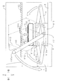
- FIG. 1 is a layout diagram of the contactless power supply device of the first embodiment.
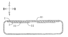
- FIG. 2 is an enlarged view in the frame II of FIG.
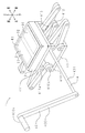
- FIG. 3 is a perspective view of a portion above the drive unit of the contactless power feeding device.
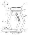
- FIG. 4 is a block diagram of the contactless power feeding device.
- FIG. 5 is a left side view of the contactless power feeding device in a contact state.
- FIG. 6 is an enlarged view in the frame VI of FIG.
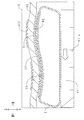
- FIG. 7 is an enlarged view of the vicinity of the airbag unit when the relative positional relationship between the vehicle and the non-contact power supply device is shifted in the non-contact power supply device.
- FIG. 8 is a left side view of a portion above the drive unit of the contactless power supply device of the second embodiment.
- FIG. 9 is a left side view (cross-sectional view) of the airbag portion of the contactless power supply device of the third embodiment.
- FIG. 10 is a left side view (cross-sectional view) of the buffer portion of the contactless power supply device of the fourth embodiment.
- FIG. 11 is a perspective view of a portion above the drive unit of the contactless power supply device of the fifth embodiment.
- FIG. 1 shows a layout of the contactless power supply device of the present embodiment.
- the non-contact electric power feeder 1 of this embodiment is arrange
- a front wheel 91 of the vehicle 9 rides on the contactless power supply device 1.
- the battery (secondary battery) of the vehicle 9 is charged.
- FIG. 2 shows an enlarged view in the frame II of FIG.
- the contactless power supply device 1 includes an airbag unit 2, a power supply unit 3, a drive unit 4, a base 5, and a power supply region R ⁇ b> 1.
- the base 5 is made of rubber and has a plate shape.
- the base 5 is placed in the parking space.
- a pair of left and right positioning portions 50 are recessed in the front portion of the upper surface of the base 5.
- the front wheel 91 of the vehicle is accommodated in the positioning unit 50. That is, the vehicle 9 is positioned by the positioning unit 50.
- FIG. 3 is a perspective view of a portion above the drive unit of the contactless power supply device of the present embodiment.
- the drive unit 4 includes an input unit 40 and a link mechanism unit 41.
- the link mechanism portion 41 includes a first wall portion 410, a second wall portion 411, five first arms 412, and five second arms 413.
- the first wall portion 410 is made of metal and has a rectangular plate shape.
- the first wall portion 410 is disposed on the upper surface of the base 5.
- Five support portions 410 a are arranged on the upper surface of the first wall portion 410.
- the five support portions 410 a are disposed at the four corners and the center of the first wall portion 410.
- the second wall portion 411 is made of metal and has a rectangular plate shape.
- the second wall portion 411 is disposed immediately above the first wall portion 410.
- Each of the first wall portion 410 and the second wall portion 411 extends in the horizontal direction.
- the first wall portion 410 and the second wall portion 411 are parallel to each other.
- Five support portions 411 a are disposed on the lower surface of the second wall portion 411.
- the five support portions 411 a are disposed at the four corners and the center of the second wall portion 411.
- the five support portions 410a and the five support portions 411a face each other in the vertical direction.
- the first arm 412 is made of metal and has a beam shape.
- the lower end of the first arm 412 is swingably attached to the support portion 410 a of the first wall portion 410.
- the second arm 413 is made of metal and has a beam shape.
- the upper end of the second arm 413 is swingably attached to the support part 411a of the second wall part 411.
- the upper end of the first arm 412 and the lower end of the second arm 413 are connected to each other so as to be swingable.
- the input unit 40 includes a lever 400 and a shaft 401.
- the shaft 401 is made of metal and has a round bar shape.
- the shaft 401 extends in the left-right direction.
- the right end of the shaft 401 is fixed to the lower end of the central first arm 412 in the central support portion 410 a of the first wall portion 410.
- the lever 400 is made of metal and has a beam shape.
- the lever 400 extends in the vertical direction.
- the lower end of the lever 400 is fixed to the left end of the shaft 401.
- a grip 400 a protrudes from the upper end of the lever 400.
- the central first arm 412 swings upward via the shaft 401.
- the moving direction of the second wall portion 411 is limited to the vertical direction by the first arm 412 and the second arm 413 at the four corners. For this reason, the 2nd wall part 411 moves upwards.
- the movement amount of the second wall portion 411 can be adjusted by the swing amount of the lever 400.
- the airbag portion 2 is made of silicone rubber and has a bag shape (cuboid box shape).
- the airbag part 2 is disposed on the upper surface of the second wall part 411.
- the air bag portion 2 is filled with air at a predetermined air pressure.
- FIG. 4 shows a block diagram of the contactless power supply device of the present embodiment.
- the power feeding unit 3 includes a pair of front and rear electrodes 30, an AC power supply 31, and a cover film 32.
- the electrode 30 includes amine-crosslinked acrylic rubber and silver particles. Amine-crosslinked acrylic rubber is included in the concept of “elastomer” of the present invention. Silver particles are included in the concept of the “conductive material” of the present invention. The silver particle content is 38 vol% when the volume of the electrode 30 is 100 vol%.
- the electrode 30 has a rectangular film shape.
- the pair of front and rear electrodes 30 are disposed on the upper surface of the wall portion above the airbag portion 2.
- the cover film 32 is made of silicone rubber and has a rectangular film shape.
- the cover film 32 covers the upper surfaces of the upper and lower walls of the pair of front and rear electrodes 30 and the airbag part 2 from above.
- the power feeding region R ⁇ b> 1 is set on the upper surface of the cover film 32.
- the positional relationship between the power receiving region R2 and the cover film 32 (that is, the power feeding unit 3) is included in the present invention in which the power feeding unit is “disposed facing the power receiving region”.
- the power feeding region R1 includes a pair of front and rear electrodes 30.
- the under cover 92 of the vehicle 9 is disposed above the cover film 32.
- the under cover 92 has a corrugated shape.
- a pair of front and rear electrodes 902 are disposed on the upper surface of the under cover 92.
- the power receiving region R ⁇ b> 2 is set on the lower surface of the under cover 92.
- the power receiving region R2 includes a pair of front and rear electrodes 902. As shown in FIG. 1, in a state where the front wheel 91 is accommodated in the positioning unit 50, the power receiving region R2 and the power feeding region R1 face each other in the vertical direction. In addition, the electrode 902 and the electrode 30 face each other in the vertical direction.
- the power receiving device 90 of the vehicle 9 includes a bridge rectifier circuit 900, a battery (secondary battery) 901, the pair of front and rear electrodes 902 described above, and the power receiving region R2 described above. .
- the bridge rectifier circuit 900 is a so-called full-wave rectifier circuit.
- the bridge rectifier circuit 900 includes four diodes 900a.
- the pair of front and rear electrodes 902 and the battery 901 are electrically connected via the bridge rectifier circuit 900. For this reason, the voltage application direction to the battery 901 is constant even when the polarity of the pair of front and rear electrodes 30 is reversed during power supply described later.
- An under cover 92 and a cover film 32 are interposed from the upper side to the lower side between the electrode 902 and the electrode 30 facing in the vertical direction. At the time of power supply to be described later, a dielectric layer is formed between the electrode 902 and the electrode 30 by the under cover 92 and the cover film 32.
- FIG. 5 the left view in the contact state of the non-contact electric power feeder of this embodiment is shown.
- FIG. 5 corresponds to FIG. 2 (separated state).
- the driver gets on the base 5 with the vehicle 9. Then, the front wheel 91 is put into the positioning unit 50. This state is the separated state shown in FIG. Next, as shown in FIGS. 2 and 5, the driver moves the second wall portion 411 upward by gripping the grip 400a and swinging the lever 400 downward.
- FIG. 6 shows an enlarged view in the frame VI of FIG.
- a dashed-dotted line in FIG. 6 is the shape of the wall part above the airbag part 2, the pair of front and rear electrodes 30, and the cover film 32 in the separated state of FIG.
- the upper wall portion of the airbag portion 2, the pair of front and rear electrodes 30, and the cover film 32 follow the shape of the lower surface (outer surface) of the undercover 92 to corrugate Is deformed.
- the power feeding region R1 and the power receiving region R2 are in surface contact with each other.
- FIG. 7 shows an enlarged view of the vicinity of the airbag portion when the relative positional relationship between the vehicle and the contactless power supply device of the contactless power supply device of this embodiment is shifted.
- FIG. 7 corresponds to FIG.
- the second wall portion 411 is displaced forward (orthogonal direction)
- the front and rear walls of the airbag portion 2 are inclined so as to absorb the displacement.
- the power feeding region R1 remains in close contact with the power receiving region R2.
- the power feeding region R1 and the power receiving region R2 are difficult to slide.
- the electrode 30 includes an elastomer and a conductive material.
- the cover film 32 is made of an elastomer.
- the airbag portion 2 is made of an elastomer.
- the airbag portion 2 is filled with air. For this reason, the electric power feeding part 3 and the airbag part 2 are flexible. Therefore, as shown in FIG. 6, when the power feeding region R1 and the power receiving region R2 come into contact with each other, the power feeding unit 3 and the airbag unit 2 are deformed so that the power feeding region R1 follows the outer surface shape of the power receiving region R2. Can be deformed.
- the contact area of the interface between the power feeding region R1 and the power receiving region R2 can be widened. For this reason, power transmission efficiency becomes high. Further, the power feeding region R1 can be elastically contacted with the power receiving region R2 by the urging force of the flexible power feeding unit 3 and the airbag unit 2. For this reason, at the time of electric power supply, electric power feeding area
- the power feeding region R1 can be freely deformed following the outer surface shape of the power receiving region R2. For this reason, the freedom degree of design of the outer surface shape of power receiving area
- the airbag portion 2 is filled with air. Compared to liquid, gas is highly compressible. For this reason, even when the upper wall portion of the airbag portion 2 is deformed, the influence of the deformation on the lower wall portion and the horizontal wall portion of the airbag portion 2 is small. Therefore, the airbag portion 2 is not easily deformed in the horizontal direction.
- the contactless power supply device 1 of the present embodiment as shown in FIG. 7, after the power feeding region R1 and the power receiving region R2 once contact each other, the relative position between the vehicle 9 and the contactless power feeding device 1 is determined. Even when the relationship is shifted in the horizontal direction, the power feeding region R1 and the power receiving region R2 are not easily displaced. For this reason, it is difficult for the power feeding region R1 and the power receiving region R2 to be in sliding contact.
- the drive unit 4 is arranged.
- the power feeding region R1 can be moved with respect to the power receiving region R2.
- the elastic contact force of the power feeding region R1 with respect to the power receiving region R2 can be adjusted.
- the height of the power feeding region R1 can be adjusted according to the height of the power receiving region R2. For this reason, regardless of the vehicle type (regardless of the height of the power receiving area R2 of the vehicle 9), the power feeding area R1 can be reliably brought into elastic contact with the power receiving area R2.
- the power supply region R1 can be moved manually through the drive unit 4.
- the non-contact electric power feeder 1 can be installed easily and easily, for example also in parking spaces, parking lots, etc. of a general household, an apartment, a store, etc.
- the power feeding region R1 is moved by human power, the manufacturing cost of the contactless power feeding device 1 can be reduced.
- the structure of the non-contact power feeding device 1 can be simplified.
- region R1 can be reciprocated to an up-down direction.
- the power feeding region R1 and the power receiving region R2 are less likely to slide.
- the link mechanism 41 the second wall 411 can be kept parallel to the first wall 410 regardless of the vertical position of the second wall 411.
- the non-contact electric power feeder 1 of this embodiment is provided with the positioning part 50, as shown in FIG. For this reason, it is possible to easily align the power feeding region R1 and the power receiving region R2 without using a sensor or the like.
- ⁇ Second embodiment> The difference between the contactless power supply device of the present embodiment and the contactless power supply device of the first embodiment is that a buffer member is disposed on the central second arm. Here, only differences will be described.
- FIG. 8 shows a left side view of a portion above the drive unit of the contactless power feeding device of the present embodiment.
- the second arm 413 at the center includes a concave member 413a and a convex member 413b.
- the upward convex portion of the convex member 413b is accommodated in the downward concave portion of the concave member 413a so as to be able to reciprocate.
- a stopper (not shown) is disposed between the convex portion and the concave portion in order to prevent the convex portion from completely falling out of the concave portion.
- a coil spring 413c is interposed between the concave member 413a and the convex member 413b.
- the contactless power supply device according to the present embodiment and the contactless power supply device according to the first embodiment have the same functions and effects with respect to parts having the same configuration. Further, according to the contactless power feeding device of the present embodiment, when switching from the separated state shown in FIG. 2 to the contact state shown in FIG. 5, the impact applied to the power feeding region R1 and the power receiving region R2 is applied to the coil. It can be relaxed by the spring 413c. In addition, the power supply region R1 can be in close contact with the power receiving region R2 when power is supplied.
- ⁇ Third embodiment> The difference between the contactless power supply device of the present embodiment and the contactless power supply device of the first embodiment is that an electrode and a cover film are arranged on the lower surface of the wall portion above the airbag portion. .
- an electrode and a cover film are arranged on the lower surface of the wall portion above the airbag portion.
- FIG. 9 shows a left side view (cross-sectional view) of the airbag portion of the contactless power supply device of this embodiment.
- a pair of front and rear electrodes 30 and a cover film 32 are disposed on the lower surface of the wall portion above the airbag portion 2.
- the cover film 32 covers the pair of front and rear electrodes 30 from below.
- a power feeding region R1 is set on the upper surface of the wall portion above the airbag portion 2.
- a wall portion above the airbag unit 2 is interposed between the power receiving region R2 and the power feeding unit 3.
- the positional relationship between the power receiving region R2 and the power feeding unit 3 is included in a form in which the power feeding unit is “disposed facing the power receiving region” in the present invention.
- a dielectric layer is formed between the electrode 902 (see FIG. 6) and the electrode 30 by the under cover 92 (see FIG. 6) and the wall portion above the airbag portion 2.
- the contactless power supply device according to the present embodiment and the contactless power supply device according to the first embodiment have the same functions and effects with respect to parts having the same configuration. Further, according to the contactless power supply device of the present embodiment, the pair of front and rear electrodes 30 and the cover film 32 are accommodated inside the airbag portion 2. For this reason, the pair of front and rear electrodes 30 can be protected from the external environment.
- ⁇ Fourth embodiment> The difference between the contactless power supply device of this embodiment and the contactless power supply device of the first embodiment is that a cushioning portion made of urethane foam is arranged instead of the airbag portion.
- a cushioning portion made of urethane foam is arranged instead of the airbag portion.
- FIG. 10 shows a left side view (cross-sectional view) of the buffer portion of the contactless power supply device of this embodiment. Note that portions corresponding to those in FIG. 6 are denoted by the same reference numerals.
- the buffer part 20 is made of urethane foam.
- a pair of front and rear electrodes 30 and a cover film 32 are disposed on the upper surface of the buffer portion 20. On the upper surface of the cover film 32, a power feeding region R1 is set.
- the contactless power supply device according to the present embodiment and the contactless power supply device according to the first embodiment have the same functions and effects with respect to parts having the same configuration. Further, according to the contactless power supply device of the present embodiment, the structure of the buffer portion 20 is simplified.
- the difference between the contactless power supply device of the present embodiment and the contactless power supply device of the first embodiment is that a coil is disposed instead of an electrode.
- FIG. 11 the perspective view of the part above the drive part of the non-contact electric power feeder of this embodiment is shown.
- the coil 33 includes amine-crosslinked acrylic rubber and silver particles. The content of the silver particles is 38 vol% when the volume of the electrode 30 is 100 vol%.
- the coil 33 has a spiral shape and a thin film shape.
- the coil 33 is disposed on the upper surface of the airbag unit 2.
- the cover film 32 covers the coil 33 from above.
- a power feeding region R1 is set on the upper surface of the cover film 32.
- a coil 903 is disposed in the power receiving region R2 of the vehicle.
- the coil 33 and the coil 903 are opposed to each other in the vertical direction.
- the contactless power supply device according to the present embodiment and the contactless power supply device according to the first embodiment have the same functions and effects with respect to parts having the same configuration. Further, according to the contactless power supply device of the present embodiment, power can be supplied to the battery by using electromagnetic induction between the power supply side coil 33 and the power reception side coil 903.
- the type of gas filled in the airbag part 2 is not particularly limited. Nitrogen, a noble gas, etc. may be sufficient.
- piping a pipe, a tube, a hose, etc.
- a pressure gauge may be set in the airbag portion 2. In this way, the separated state shown in FIG. 2 and the contact state shown in FIG. 5 can be detected by pressure change. Further, a liquid (water, oil, etc.) may be put into the airbag part 2.
- the airbag part 2 itself expands and contracts in the vertical direction (for example, a bellows shape is given to the horizontal wall part of the airbag part 2.
- a pipe is connected to the airbag part 2 to allow gas to enter and exit.
- the separated state shown in FIG. 2 and the contact state shown in FIG. 5 may be switched.
- the drive unit 4 becomes unnecessary.
- the structure of the drive part 4 is not specifically limited. A cam mechanism, a fluid cylinder, a robot, or the like may be used.
- the lower surface shape and inclination of the under cover 92 of the vehicle 9 are not particularly limited. There may be irregularities such as fins and holes. Moreover, a plane, a curved surface, etc. may be sufficient. Further, the position of the power receiving region R2 in the vehicle 9 is not particularly limited. It may be a front bumper lower surface, a rear bumper lower surface, a body side surface, a body upper surface, or the like.
- the arrangement method of the electrode 30 and the coil 33 with respect to the airbag part 2 is not particularly limited.
- the electrode 30 and the coil 33 produced separately from the airbag unit 2 may be attached to the airbag unit 2. Further, the electrode 30 and the coil 33 may be sandwiched between the airbag portion 2 and the cover film 32 and laminated.
- the electrode 30 and the coil 33 may be formed by printing paint (for example, screen printing, inkjet printing, flexographic printing, gravure printing, pad printing, lithography, etc.) on the airbag unit 2.
- the electrode 30 and the coil 33 may be formed by applying a paint to the airbag portion 2 (for example, a dipping method, a spray method, a bar coating method, or the like).
- the number, arrangement area, and shape of the electrodes 30 and the coils 33 are not particularly limited. Further, the arrangement number, arrangement area, and shape of the electrodes 30 may not match the arrangement number, arrangement area, and shape of the electrodes 902. Similarly, the arrangement number, arrangement area, and shape of the coil 33 may not match the arrangement number, arrangement area, and shape of the coil 903. For example, when the arrangement number of the electrodes 30 is larger than the arrangement number of the electrodes 902 (when the arrangement area of the electrodes 30 is made larger than the arrangement area of the electrodes 902), the electrodes 30 and the electrodes 902 are opposed in the vertical direction in a wide range. Can be made. For this reason, precise alignment between the contactless power supply device 1 and the vehicle 9 is not necessary.
- the shape and area of the power feeding region R1 and the power receiving region R2 are not particularly limited. It is sufficient that at least the electrode 30 and the coil 33 are disposed in the power supply region R1 when viewed from above or below. It is sufficient that at least the electrode 902 and the coil 903 are disposed in the power receiving region R2 when viewed from above or below.
- the material of the airbag part 2 and the cover film 32 is not particularly limited. Resins and elastomers may be used alone or in combination.
- the elastomer may contain additives such as a plasticizer, a processing aid, a crosslinking agent, a crosslinking accelerator, a crosslinking aid, an antiaging agent, a softening agent, and a coloring agent.
- acrylic rubber, ethylene-propylene copolymer rubber, natural rubber, styrene-butadiene copolymer rubber, acrylonitrile-butadiene copolymer are used from the viewpoint of elasticity at room temperature.
- Suitable resins for the airbag portion 2 and the cover film 32 include polyester resins such as polyethylene terephthalate (PET) and polyethylene naphthalate (PEN), modified polyester resins (urethane modified polyester resins, epoxy modified polyester resins, acrylic modified polyester resins). Polyether urethane resin, polycarbonate urethane resin, vinyl chloride-vinyl acetate copolymer, phenol resin, acrylic resin, polyamide imide resin, polyamide resin, nitrocellulose, modified celluloses (cellulose, acetate, butyrate (CAB), Cellulose acetate, propionate (CAP), etc.).
- polyester resins such as polyethylene terephthalate (PET) and polyethylene naphthalate (PEN)
- modified polyester resins urethane modified polyester resins, epoxy modified polyester resins, acrylic modified polyester resins.
- the material of the buffer part 20 is not particularly limited. Any resin foam or elastomer foam may be used.
- resin foam or elastomer foam may be used.
- the elastomer does not include any of sulfur, sulfur compounds, and organic peroxides from the viewpoint of suppressing oxidation and sulfurization of the metal particles. It is preferable.
- the elastomer it is preferable to use one or more selected from sulfur, a sulfur compound, a crosslinked rubber crosslinked without using an organic peroxide, and a thermoplastic elastomer.
- the former crosslinked rubber may be a rubber that is crosslinked without using a sulfur-containing vulcanizing agent, vulcanization accelerator, or peroxide-based crosslinking agent.
- a crosslinked rubber include EPDM, amine-crosslinked acrylic rubber, isocyanate-crosslinked urethane rubber, and isocyanate-crosslinked liquid butadiene rubber.
- thermoplastic elastomer examples include polyester-based thermoplastic elastomer (TPEE), polyurethane-based thermoplastic elastomer (TPU), polyolefin-based thermoplastic elastomer (TPO), polyamide-based thermoplastic elastomer, styrene-based block copolymer-based thermoplastic elastomer (SIS, SBS, etc.).
- TPEE polyester-based thermoplastic elastomer
- TPU polyurethane-based thermoplastic elastomer
- TPO polyolefin-based thermoplastic elastomer
- SIS styrene-based block copolymer-based thermoplastic elastomer
- the elastomer of the electrode 30 and the coil 33 is not particularly limited. What is necessary is just to select suitably from the said elastomer enumerated as an elastomer suitable for the airbag part 2 and the cover film 32.
- FIG. Moreover, the kind of electrically conductive material is not specifically limited.
- One or more metal powders such as gold, copper, nickel, rhodium, palladium, chromium, titanium, platinum, iron, and alloys thereof can be used. Carbon materials such as carbon black, carbon nanotubes, and graphite may be used.
- the specific gravity of the conductive material can be reduced as compared with the case where the conductive material is made of only metal. Therefore, when it is made into a paint, sedimentation of the conductive material is suppressed and dispersibility is improved. Also, by processing the particles, various shapes of conductive materials can be easily manufactured. In addition, the cost of the conductive material can be reduced.
- metal materials such as silver listed above may be used.
- carbon materials such as carbon black, metal oxides such as calcium carbonate, titanium dioxide, aluminum oxide, and barium titanate, inorganic substances such as silica, resins such as acrylic and urethane, and the like may be used. .
- the content of the conductive material may be determined as appropriate so that both conductivity and flexibility can be achieved.
- the content of the conductive material is preferably 10 vol% or more when the volume of the electrode 30 and the coil 33 is 100 vol%. It is more preferable that it is 15 vol% or more.
- content of an electrically conductive material is 40 vol% or less when the volume of the electrode 30 and the coil 33 is 100 vol%. It is more preferable that it is 25 vol% or less.
Landscapes
- Engineering & Computer Science (AREA)
- Power Engineering (AREA)
- Mechanical Engineering (AREA)
- Computer Networks & Wireless Communication (AREA)
- Transportation (AREA)
- Electric Propulsion And Braking For Vehicles (AREA)
- Charge And Discharge Circuits For Batteries Or The Like (AREA)
Abstract
汎用性が高く、送電効率が高い無接点給電装置を提供することを課題とする。 無接点給電装置(1)は、車両(9)の受電領域(R2)に当接することにより電力を供給する給電領域(R1)と、緩衝部(2)と、緩衝部(2)に配置されると共に受電領域(R2)に対向して配置され、エラストマーおよび導電材を含む導電部(30)を有する給電部(3)と、を備える。緩衝部(2)および給電部(3)が変形することにより、給電領域(R1)は、受電領域(R2)の形状に倣って変形する。
Description
本発明は、例えば静電容量型や電磁誘導型などの無接点給電装置に関する。
無接点給電装置の中には、給電側の電極と受電側の電極との間にコンデンサを形成し、静電容量により電力を供給する静電容量型の無接点給電装置がある(例えば特許文献1参照)。また、給電側のコイルと受電側のコイルとの間の電磁誘導を利用して電力を供給する電磁誘導型の無接点給電装置がある(例えば特許文献2~4参照)。
無接点給電装置は、例えば駐車場の路面などに配置されている。無接点給電装置の上面には、給電領域が配置されている。一方、車両の下面には、受電領域が配置されている。
一例として、電磁誘導型の無接点給電装置の場合、電力供給時においては、給電領域を受電領域に当接させる。そして、給電側のコイルと受電側のコイルとを電磁結合させて、車両のバッテリ(二次電池)に電力を供給する。
ここで、給電側のコイルと受電側のコイルとが離間していると、送電効率が著しく低下する。このため、給電領域と受電領域とを密着させる必要がある。したがって、給電領域および受電領域を、共に平坦面とする必要がある。こうすると、給電領域と受電領域とを密着させることができる。
しかしながら、空気抵抗対策、飛び石対策などの観点から、車両の下面に大きな平坦面を確保することは困難である。このため、給電領域と受電領域とを密着させることは困難である。ここで、給電領域と受電領域とを型対称に形成することも考えられる。例えば、無接点給電装置の給電領域を凸形状にし、車両の受電領域を当該凸形状に型対称な凹形状にすることも考えられる。ところが、この場合、受電領域の形状が凹形状ではない車両に電力を供給する際に、やはり送電効率が著しく低下してしまう。すなわち、汎用性に欠ける。
この点、特許文献4には、柔軟な給電側コアおよび受電側コアを備える電磁誘導型の無接点給電装置が開示されている。給電側コアおよび受電側コアは、各々、軟磁性体製である。軟磁性体は、ゴムおよび樹脂の少なくとも一方に、軟磁性材料が分散されることにより、形成されている。同文献記載の無接点給電装置によると、給電側コアの上端の平坦面と、受電側コアの下端の平坦面と、が互いに平行でない場合であっても、給電側コアおよび受電側コアが変形することにより、給電側コアと受電側コアとを面接触させることができる。
ところが、特許文献4の無接点給電装置の場合、導電部(給電側コイル、受電側コイル)自体は変形しない。このため、やはり、給電側コイルと受電側コイルとが離間しやすい。したがって、送電効率が低下しやすい。
本発明の無接点給電装置は、上記課題に鑑みて完成されたものである。本発明は、汎用性が高く、送電効率が高い無接点給電装置を提供することを目的とする。
(1)上記課題を解決するため、本発明の無接点給電装置は、車両の受電領域に当接することにより電力を供給する給電領域を備える無接点給電装置であって、緩衝部と、該緩衝部に配置されると共に該受電領域に対向して配置され、エラストマーおよび導電材を含む導電部を有する給電部と、を備え、該緩衝部および該給電部が変形することにより、該給電領域は、該受電領域の形状に倣って変形することを特徴とする。
ここで、給電部が「受電領域に対向して配置され」る形態には、給電部の表面に給電領域が配置される場合は、直接、給電部と受電領域とが互いに向かい合っている形態が含まれる。また、別部材の表面に給電領域が配置される場合は、別部材を介して間接的に、給電部と受電領域とが互いに向かい合っている形態が含まれる。
本発明の無接点給電装置によると、給電部の導電部(例えば、電極、コイルなど)がエラストマーを含んでいる。このため、給電部が柔軟である。したがって、給電領域と受電領域とが接触する際、緩衝部および給電部が変形することにより、給電領域を、受電領域の形状に倣って、変形させることができる。
本発明の無接点給電装置によると、給電領域と受電領域との界面の接触面積を広くすることができる。このため、送電効率が高くなる。また、柔軟な緩衝部、給電部の付勢力により、給電領域を受電領域に弾接させることができる。このため、電力供給時に給電領域を受電領域に密着させることができる。
また、本発明の無接点給電装置によると、給電領域を、受電領域の形状に倣って、自在に変形させることができる。このため、受電領域の形状の設計の自由度が高くなる。また、車種によらず、高い送電効率を確保することができる。すなわち、車種に対する汎用性が高くなる。
(1-1)好ましくは、上記(1)の構成において、前記給電領域は、前記緩衝部の表面および前記給電部の表面のうち、前記受電領域に近い方に配置される構成とする方がよい。本構成によると、緩衝部表面と給電部表面との位置関係に応じて、受電領域に近い方を給電領域に設定することができる。
(2)好ましくは、上記(1)の構成において、前記緩衝部は、気体入りのエアバッグ部である構成とする方がよい。以下、受電領域と給電領域とが重なる方向を「重複方向」、重複方向に直交する方向を「直交方向」と定義する。液体と比較して、気体は圧縮性が高い。このため、本構成によると、エアバッグ部の受電領域側の壁部が変形する場合であっても、当該変形が、エアバッグ部の他の壁部に与える影響が小さい。したがって、エアバッグ部が、直交方向に変形しにくい。
また、本構成によると、給電領域と受電領域とが一旦当接した後、車両と無接点給電装置との相対的な位置関係がずれる場合であっても、給電領域と受電領域とがずれにくい。その理由は、エアバッグ部の直交方向の壁部が傾斜することにより、当該位置ずれを吸収することができるからである。このように、本構成によると、給電領域と受電領域とが摺接しにくい。
(3)好ましくは、上記(1)または(2)の構成において、前記導電部は、コイルまたは電極である構成とする方がよい。本構成は、本発明の無接点給電装置を、電磁誘導型または静電容量型の無接点給電装置として具現化したものである。
本構成によると、電力供給時において、給電側のコイルと、受電側のコイルと、が離間しにくい。また、電力供給時において、給電側の電極と、受電側の電極と、が離間しにくい。
(4)好ましくは、上記(1)ないし(3)のいずれかの構成において、前記受電領域に対して、前記給電領域を離接可能な駆動部を備える構成とする方がよい。本構成によると、受電領域に対して給電領域を動かすことができる。また、受電領域に対する給電領域の弾接力を調整することができる。
(5)好ましくは、上記(4)の構成において、前記受電領域と前記給電領域とが重なる方向を重複方向、該重複方向に直交する方向を直交方向として、前記駆動部は、人力が入力される入力部と、該入力部に連結され該給電領域を該重複方向に往復動させるリンク機構部と、を有する構成とする方がよい。
本構成によると、人力により給電領域を動かすことができる。このため、電力により給電領域を動かす場合と比較して、無接点給電装置を簡単に設置することができる。したがって、一般家庭などにおいても、無接点給電装置を手軽に使用することができる。また、人力により給電領域を動かすため、無接点給電装置の製造コストを削減することができる。また、無接点給電装置の構造を簡単にすることができる。また、本構成によると、給電領域を重複方向に往復動させることができる。このため、給電領域の軌道に直交方向成分が含まれる場合と比較して、給電領域と受電領域とが摺接しにくい。
(6)好ましくは、上記(1)ないし(5)のいずれかの構成において、電力供給時に前記給電領域と前記受電領域とが当接するように、前記車両の位置を決める位置決め部を備える構成とする方がよい。本構成によると、給電領域と受電領域との位置合わせを簡単に行うことができる。
本発明によると、汎用性が高く、送電効率が高い無接点給電装置を提供することができる。
1:無接点給電装置、2:エアバッグ部、3:給電部、4:駆動部、5:ベース、9:車両。
20:緩衝部、30:電極、31:交流電源、32:カバーフィルム、33:コイル、40:入力部、41:リンク機構部、50:位置決め部、90:受電装置、91:前輪、92:アンダーカバー。
400:レバー、400a:グリップ、401:シャフト、410:第一壁部、410a:支持部、411:第二壁部、411a:支持部、412:第一アーム、413:第二アーム、413a:凹部材、413b:凸部材、900:ブリッジ整流回路、900a:ダイオード、901:バッテリ、902:電極、903:コイル。
R1:給電領域、R2:受電領域。
20:緩衝部、30:電極、31:交流電源、32:カバーフィルム、33:コイル、40:入力部、41:リンク機構部、50:位置決め部、90:受電装置、91:前輪、92:アンダーカバー。
400:レバー、400a:グリップ、401:シャフト、410:第一壁部、410a:支持部、411:第二壁部、411a:支持部、412:第一アーム、413:第二アーム、413a:凹部材、413b:凸部材、900:ブリッジ整流回路、900a:ダイオード、901:バッテリ、902:電極、903:コイル。
R1:給電領域、R2:受電領域。
以下、本発明の無接点給電装置の実施の形態について説明する。
<第一実施形態>
[無接点給電装置の配置]
まず、本実施形態の無接点給電装置の配置について説明する。以下に示す実施形態においては、上下方向が本発明の「重複方向」に相当する。また、水平方向、前後方向、左右方向が、本発明の「直交方向」に相当する。
[無接点給電装置の配置]
まず、本実施形態の無接点給電装置の配置について説明する。以下に示す実施形態においては、上下方向が本発明の「重複方向」に相当する。また、水平方向、前後方向、左右方向が、本発明の「直交方向」に相当する。
図1に、本実施形態の無接点給電装置の配置図を示す。図1に示すように、本実施形態の無接点給電装置1は、一般家庭の駐車スペースに配置されている。車両9の前輪91は、無接点給電装置1に乗り上げている。この状態において、車両9のバッテリ(二次電池)の充電が行われる。
[無接点給電装置の機械的構成]
次に、本実施形態の無接点給電装置の機械的構成について説明する。図2に、図1の枠II内の拡大図を示す。図1、図2に示すように、無接点給電装置1は、エアバッグ部2と、給電部3と、駆動部4と、ベース5と、給電領域R1と、を備えている。
次に、本実施形態の無接点給電装置の機械的構成について説明する。図2に、図1の枠II内の拡大図を示す。図1、図2に示すように、無接点給電装置1は、エアバッグ部2と、給電部3と、駆動部4と、ベース5と、給電領域R1と、を備えている。
ベース5は、ゴム製であって板状を呈している。ベース5は、駐車スペースに載置されている。ベース5の上面の前部分には、左右一対の位置決め部50が凹設されている。車両の前輪91は、当該位置決め部50に収容されている。すなわち、車両9は、位置決め部50により、位置決めされている。
図3に、本実施形態の無接点給電装置の駆動部より上の部分の斜視図を示す。図1~図3に示すように、駆動部4は、入力部40と、リンク機構部41と、を備えている。リンク機構部41は、第一壁部410と、第二壁部411と、五つの第一アーム412と、五つの第二アーム413と、を備えている。
第一壁部410は、金属製であって四角形板状を呈している。第一壁部410は、ベース5の上面に配置されている。第一壁部410の上面には、五つの支持部410aが配置されている。五つの支持部410aは、第一壁部410の四隅および中央に配置されている。
第二壁部411は、金属製であって四角形板状を呈している。第二壁部411は、第一壁部410の真上に配置されている。第一壁部410および第二壁部411は、各々、水平方向に延在している。第一壁部410と第二壁部411とは、互いに平行である。第二壁部411の下面には、五つの支持部411aが配置されている。五つの支持部411aは、第二壁部411の四隅および中央に配置されている。五つの支持部410aと、五つの支持部411aと、は上下方向に対向している。
第一アーム412は金属製であって梁状を呈している。第一アーム412の下端は、第一壁部410の支持部410aに、揺動可能に取り付けられている。第二アーム413は金属製であって梁状を呈している。第二アーム413の上端は、第二壁部411の支持部411aに、揺動可能に取り付けられている。第一アーム412の上端と、第二アーム413の下端と、は互いに揺動可能に連結されている。
入力部40は、レバー400と、シャフト401と、を備えている。シャフト401は、金属製であって丸棒状を呈している。シャフト401は、左右方向に延在している。シャフト401の右端は、第一壁部410の中央の支持部410aにおいて、中央の第一アーム412の下端に固定されている。レバー400は、金属製であって梁状を呈している。レバー400は、上下方向に延在している。レバー400の下端は、シャフト401の左端に固定されている。レバー400の上端からは、グリップ400aが突設されている。
図2に点線で示すように、操作者がグリップ400aを把持してレバー400を下方に揺動させると、シャフト401を介して、中央の第一アーム412が上方に揺動する。ここで、第二壁部411の移動方向は、四隅の第一アーム412および第二アーム413により、上下方向に限定されている。このため、第二壁部411は上方に移動する。レバー400の揺動量により、第二壁部411の移動量を調整することができる。レバー400を逆方向(上方)に揺動させると、第二壁部411は下方に移動する。
エアバッグ部2は、シリコーンゴム製であって袋状(直方体箱状)を呈している。エアバッグ部2は、第二壁部411の上面に配置されている。エアバッグ部2の内部には、所定の空気圧で、空気が充填されている。
図4に、本実施形態の無接点給電装置のブロック図を示す。図1~図4に示すように、給電部3は、前後一対の電極30と、交流電源31と、カバーフィルム32と、を備えている。電極30は、アミン架橋アクリルゴムおよび銀粒子を含んでいる。アミン架橋アクリルゴムは、本発明の「エラストマー」の概念に含まれる。銀粒子は、本発明の「導電材」の概念に含まれる。銀粒子の含有量は、電極30の体積を100vol%とした場合の38vol%である。電極30は、長方形膜状を呈している。前後一対の電極30は、エアバッグ部2の上方の壁部の上面に配置されている。
カバーフィルム32は、シリコーンゴム製であって、長方形膜状を呈している。カバーフィルム32は、前後一対の電極30およびエアバッグ部2の上方の壁部の上面を、上方から覆っている。給電領域R1は、カバーフィルム32の上面に設定されている。受電領域R2と、カバーフィルム32(つまり給電部3)と、の位置関係は、本発明における、給電部が「受電領域に対向して配置され」る形態に含まれる。上方または下方から見て、給電領域R1には、前後一対の電極30が含まれている。
カバーフィルム32の上方には、車両9のアンダーカバー92が配置されている。アンダーカバー92は、波板状を呈している。アンダーカバー92の上面には、前後一対の電極902が配置されている。受電領域R2は、アンダーカバー92の下面に設定されている。上方または下方から見て、受電領域R2には、前後一対の電極902が含まれている。図1に示すように前輪91が位置決め部50に収容された状態において、受電領域R2と給電領域R1とは、上下方向に対向している。並びに、電極902と電極30とは、上下方向に対向している。
[無接点給電装置の電気的構成]
次に、本実施形態の無接点給電装置の電気的構成について説明する。図4に示すように、車両9の受電装置90は、ブリッジ整流回路900と、バッテリ(二次電池)901と、上述した前後一対の電極902と、上述した受電領域R2と、を備えている。
次に、本実施形態の無接点給電装置の電気的構成について説明する。図4に示すように、車両9の受電装置90は、ブリッジ整流回路900と、バッテリ(二次電池)901と、上述した前後一対の電極902と、上述した受電領域R2と、を備えている。
ブリッジ整流回路900は、いわゆる全波整流回路である。ブリッジ整流回路900は、四つのダイオード900aを備えている。前後一対の電極902と、バッテリ901とは、ブリッジ整流回路900を介して、電気的に接続されている。このため、後述する電力供給時において、前後一対の電極30の極性が反転しても、バッテリ901に対する電圧印加方向は一定である。
上下方向に対向する電極902と電極30との間には、上方から下方に向かって、アンダーカバー92とカバーフィルム32とが介装されている。後述する電力供給時においては、これらアンダーカバー92およびカバーフィルム32により、電極902と電極30との間に、誘電層が形成される。
[無接点給電装置の離間状態から当接状態への切替時の動き]
次に、本実施形態の無接点給電装置の離間状態から当接状態への切替時の動きについて説明する。図5に、本実施形態の無接点給電装置の当接状態における左面図を示す。なお、図5は、図2(離間状態)に対応している。
次に、本実施形態の無接点給電装置の離間状態から当接状態への切替時の動きについて説明する。図5に、本実施形態の無接点給電装置の当接状態における左面図を示す。なお、図5は、図2(離間状態)に対応している。
まず、図1に示すように、運転者は、車両9でベース5に乗り上げる。そして、前輪91を位置決め部50に入れる。この状態が、図2に示す離間状態である。次に、運転者は、図2、図5に示すように、グリップ400aを把持してレバー400を下方に揺動させることにより、第二壁部411を上方に移動させる。
図6に、図5の枠VI内の拡大図を示す。なお、図6に一点鎖線で示すは、図2の離間状態におけるエアバッグ部2の上方の壁部、前後一対の電極30、カバーフィルム32の形状である。図6に示すように、当接状態においては、エアバッグ部2の上方の壁部、前後一対の電極30、カバーフィルム32は、アンダーカバー92の下面(外面)の形状に倣って、波板状に変形している。このため、給電領域R1と受電領域R2とが全面的に面接触している。図6に矢印で示すように、給電領域R1と受電領域R2との界面には、下方から、エアバッグ部2の空気圧縮に伴う付勢力、第二壁部411の移動による付勢力が、加わっている。このため、給電領域R1と受電領域R2とは密着している。
[無接点給電装置の電力供給時の動き]
次に、本実施形態の無接点給電装置の電力供給時の動きについて説明する。図4に示すように、交流電源31をオンにすると、前方の電極30~電極902間(コンデンサ)と、後方の電極30~電極902間(コンデンサ)と、の間の電圧印加方向が周期的に反転する。各々のコンデンサにチャージされた電荷は、ブリッジ整流回路900を介して、バッテリ901に供給される。このようにして、バッテリ901の充電が行われる。バッテリ901充電後は、レバー400を上方に揺動させることにより、第二壁部411つまり給電領域R1を下方に移動させる。
次に、本実施形態の無接点給電装置の電力供給時の動きについて説明する。図4に示すように、交流電源31をオンにすると、前方の電極30~電極902間(コンデンサ)と、後方の電極30~電極902間(コンデンサ)と、の間の電圧印加方向が周期的に反転する。各々のコンデンサにチャージされた電荷は、ブリッジ整流回路900を介して、バッテリ901に供給される。このようにして、バッテリ901の充電が行われる。バッテリ901充電後は、レバー400を上方に揺動させることにより、第二壁部411つまり給電領域R1を下方に移動させる。
図7に、本実施形態の無接点給電装置の、車両と無接点給電装置との相対的な位置関係がずれた場合の、エアバッグ部付近の拡大図を示す。なお、図7は、図6に対応している。図7に矢印で示すように、第二壁部411が前方(直交方向)にずれると、エアバッグ部2の前後両壁が、当該ずれを吸収するように、傾斜する。このため、給電領域R1は、受電領域R2に密着したままである。このように、給電領域R1と受電領域R2とは摺動しにくい。
[作用効果]
次に、本実施形態の無接点給電装置1の作用効果について説明する。本実施形態の無接点給電装置1によると、電極30がエラストマーおよび導電材を含んでいる。また、カバーフィルム32がエラストマー製である。また、エアバッグ部2がエラストマー製である。また、エアバッグ部2には、空気が充填されている。このため、給電部3およびエアバッグ部2が柔軟である。したがって、図6に示すように、給電領域R1と受電領域R2とが接触する際、給電部3およびエアバッグ部2が変形することにより、給電領域R1を、受電領域R2の外面形状に倣って、変形させることができる。
次に、本実施形態の無接点給電装置1の作用効果について説明する。本実施形態の無接点給電装置1によると、電極30がエラストマーおよび導電材を含んでいる。また、カバーフィルム32がエラストマー製である。また、エアバッグ部2がエラストマー製である。また、エアバッグ部2には、空気が充填されている。このため、給電部3およびエアバッグ部2が柔軟である。したがって、図6に示すように、給電領域R1と受電領域R2とが接触する際、給電部3およびエアバッグ部2が変形することにより、給電領域R1を、受電領域R2の外面形状に倣って、変形させることができる。
本実施形態の無接点給電装置1によると、給電領域R1と受電領域R2との界面の接触面積を広くすることができる。このため、送電効率が高くなる。また、柔軟な給電部3、エアバッグ部2の付勢力により、給電領域R1を受電領域R2に弾接させることができる。このため、電力供給時に給電領域R1を受電領域R2に密着させることができる。したがって、電力供給時において、給電側の電極30と、受電側の電極902と、が離間しにくい。
また、本実施形態の無接点給電装置1によると、給電領域R1を、受電領域R2の外面形状に倣って、自在に変形させることができる。このため、受電領域R2の外面形状の設計の自由度が高くなる。また、車種によらず、高い送電効率を確保することができる。すなわち、車種に対する汎用性が高くなる。
また、本実施形態の無接点給電装置1によると、エアバッグ部2に空気が充填されている。液体と比較して、気体は圧縮性が高い。このため、エアバッグ部2の上方の壁部が変形する場合であっても、当該変形が、エアバッグ部2の下方の壁部や水平方向の壁部に与える影響が小さい。したがって、エアバッグ部2が、水平方向に、変形しにくい。
また、本実施形態の無接点給電装置1によると、図7に示すように、給電領域R1と受電領域R2とが一旦当接した後、車両9と無接点給電装置1との相対的な位置関係が水平方向にずれる場合であっても、給電領域R1と受電領域R2とがずれにくい。このため、給電領域R1と受電領域R2とが摺接しにくい。
また、本実施形態の無接点給電装置1によると、駆動部4が配置されている。このため、図2(離間状態)、図5(当接状態)に示すように、受電領域R2に対して給電領域R1を動かすことができる。また、受電領域R2に対する給電領域R1の弾接力を調整することができる。また、図2に点線で示すように、受電領域R2の高さに応じて、給電領域R1の高さを調整することができる。このため、車種によらず(車両9の受電領域R2の高さによらず)、受電領域R2に給電領域R1を確実に弾接させることができる。
また、本実施形態の無接点給電装置1によると、駆動部4を介して、給電領域R1を人力で動かすことができる。このため、例えば一般家庭、マンション、店舗などの駐車スペース、駐車場などにおいても、無接点給電装置1を、簡単かつ手軽に設置することができる。また、人力により給電領域R1を動かすため、無接点給電装置1の製造コストを削減することができる。また、無接点給電装置1の構造を簡単にすることができる。また、リンク機構部41によると、給電領域R1を上下方向に往復動させることができる。このため、給電領域R1の軌道に水平方向成分が含まれる場合(例えば給電領域R1が揺動する場合)と比較して、給電領域R1と受電領域R2とが摺接しにくい。また、リンク機構部41によると、第二壁部411の上下方向位置に関係なく、第一壁部410に対して第二壁部411を平行に保つことができる。また、本実施形態の無接点給電装置1は、図1に示すように、位置決め部50を備えている。このため、センサなどを用いずに、給電領域R1と受電領域R2との位置合わせを簡単に行うことができる。
<第二実施形態>
本実施形態の無接点給電装置と、第一実施形態の無接点給電装置との相違点は、中央の第二アームに、緩衝部材が配置されている点である。ここでは、相違点についてのみ説明する。
本実施形態の無接点給電装置と、第一実施形態の無接点給電装置との相違点は、中央の第二アームに、緩衝部材が配置されている点である。ここでは、相違点についてのみ説明する。
図8に、本実施形態の無接点給電装置の駆動部より上の部分の左面図を示す。なお、図2と対応する部位については、同じ符号で示す。図8に示すように、中央の第二アーム413は、凹部材413aと凸部材413bとを備えている。凸部材413bの上向きの凸部は、凹部材413aの下向きの凹部に、往復動可能に収容されている。また、凸部が凹部から完全に脱落するのを抑制するために、凸部と凹部との間にはストッパ(図略)が配置されている。凹部材413aと凸部材413bとの間には、コイルばね413cが介装されている。
本実施形態の無接点給電装置と、第一実施形態の無接点給電装置とは、構成が共通する部分に関しては、同様の作用効果を有する。また、本実施形態の無接点給電装置によると、前出図2に示す離間状態から、前出図5に示す当接状態に切り替える際に、給電領域R1および受電領域R2に加わる衝撃を、コイルばね413cにより、緩和することができる。また、電力供給時に給電領域R1を受電領域R2に密着させることができる。
<第三実施形態>
本実施形態の無接点給電装置と、第一実施形態の無接点給電装置との相違点は、エアバッグ部の上方の壁部の下面に、電極とカバーフィルムとが配置されている点である。ここでは、相違点についてのみ説明する。
本実施形態の無接点給電装置と、第一実施形態の無接点給電装置との相違点は、エアバッグ部の上方の壁部の下面に、電極とカバーフィルムとが配置されている点である。ここでは、相違点についてのみ説明する。
図9に、本実施形態の無接点給電装置のエアバッグ部の左面図(断面図)を示す。なお、図6と対応する部位については、同じ符号で示す。図9に示すように、エアバッグ部2の上方の壁部の下面には、前後一対の電極30と、カバーフィルム32と、が配置されている。カバーフィルム32は、前後一対の電極30を、下方から覆っている。エアバッグ部2の上方の壁部の上面には、給電領域R1が設定されている。
受電領域R2と給電部3との間には、エアバッグ部2の上方の壁部が介在している。受電領域R2と給電部3との位置関係は、本発明における、給電部が「受電領域に対向して配置され」る形態に含まれる。
電力供給時においては、アンダーカバー92(図6参照)およびエアバッグ部2の上方の壁部により、電極902(図6参照)と電極30との間に、誘電層が形成される。
本実施形態の無接点給電装置と、第一実施形態の無接点給電装置とは、構成が共通する部分に関しては、同様の作用効果を有する。また、本実施形態の無接点給電装置によると、前後一対の電極30と、カバーフィルム32と、がエアバッグ部2の内部に収容されている。このため、前後一対の電極30を外部環境から保護することができる。
<第四実施形態>
本実施形態の無接点給電装置と、第一実施形態の無接点給電装置との相違点は、エアバッグ部の代わりにウレタン発泡体製の緩衝部が配置されている点である。ここでは、相違点についてのみ説明する。
本実施形態の無接点給電装置と、第一実施形態の無接点給電装置との相違点は、エアバッグ部の代わりにウレタン発泡体製の緩衝部が配置されている点である。ここでは、相違点についてのみ説明する。
図10に、本実施形態の無接点給電装置の緩衝部の左面図(断面図)を示す。なお、図6と対応する部位については、同じ符号で示す。図10に示すように、緩衝部20は、ウレタン発泡体製である。緩衝部20の上面には、前後一対の電極30と、カバーフィルム32と、が配置されている。カバーフィルム32の上面には、給電領域R1が設定されている。
本実施形態の無接点給電装置と、第一実施形態の無接点給電装置とは、構成が共通する部分に関しては、同様の作用効果を有する。また、本実施形態の無接点給電装置によると、緩衝部20の構造が簡単になる。
<第五実施形態>
本実施形態の無接点給電装置と、第一実施形態の無接点給電装置との相違点は、電極の代わりに、コイルが配置されている点である。ここでは、相違点についてのみ説明する。図11に、本実施形態の無接点給電装置の駆動部より上の部分の斜視図を示す。なお、図3と対応する部位については、同じ符号で示す。図11に示すように、コイル33は、アミン架橋アクリルゴムおよび銀粒子を含んでいる。銀粒子の含有量は、電極30の体積を100vol%とした場合の38vol%である。コイル33は、渦巻状かつ薄膜状を呈している。コイル33は、エアバッグ部2の上面に配置されている。カバーフィルム32は、コイル33を、上方から覆っている。カバーフィルム32の上面には、給電領域R1が設定されている。図11に細線で示すように、車両の受電領域R2には、コイル903が配置されている。コイル33とコイル903とは、上下方向に対向している。
本実施形態の無接点給電装置と、第一実施形態の無接点給電装置との相違点は、電極の代わりに、コイルが配置されている点である。ここでは、相違点についてのみ説明する。図11に、本実施形態の無接点給電装置の駆動部より上の部分の斜視図を示す。なお、図3と対応する部位については、同じ符号で示す。図11に示すように、コイル33は、アミン架橋アクリルゴムおよび銀粒子を含んでいる。銀粒子の含有量は、電極30の体積を100vol%とした場合の38vol%である。コイル33は、渦巻状かつ薄膜状を呈している。コイル33は、エアバッグ部2の上面に配置されている。カバーフィルム32は、コイル33を、上方から覆っている。カバーフィルム32の上面には、給電領域R1が設定されている。図11に細線で示すように、車両の受電領域R2には、コイル903が配置されている。コイル33とコイル903とは、上下方向に対向している。
本実施形態の無接点給電装置と、第一実施形態の無接点給電装置とは、構成が共通する部分に関しては、同様の作用効果を有する。また、本実施形態の無接点給電装置によると、給電側のコイル33と受電側のコイル903との間の電磁誘導を利用して、バッテリに電力を供給することができる。
<その他>
以上、本発明の無接点給電装置の実施の形態について説明した。しかしながら、実施の形態は上記形態に特に限定されるものではない。当業者が行いうる種々の変形的形態、改良的形態で実施することも可能である。
以上、本発明の無接点給電装置の実施の形態について説明した。しかしながら、実施の形態は上記形態に特に限定されるものではない。当業者が行いうる種々の変形的形態、改良的形態で実施することも可能である。
エアバッグ部2に充填する気体の種類は特に限定しない。窒素、希ガスなどであってもよい。また、エアバッグ部2に配管(パイプ、チューブ、ホースなど)を接続し気体を出入り可能にしてもよい。こうすると、エアバッグ部2の内圧を調整することができる。また、エアバッグ部2に圧力計を設定してもよい。こうすると、図2に示す離間状態や、図5に示す当接状態を、圧力変化により検出することができる。また、エアバッグ部2に、液体(水、オイルなど)を入れてもよい。また、エアバッグ部2自体が上下方向に伸縮する(例えば、エアバッグ部2の水平方向の壁部に蛇腹形状を付与する。並びに、エアバッグ部2に配管を接続し気体を出入り可能にする。)ことにより、図2に示す離間状態と、図5に示す当接状態と、を切り替えてもよい。こうすると、駆動部4が不要になる。また、駆動部4の構成は特に限定しない。カム機構、流体シリンダ、ロボットなどを用いてもよい。
また、車両9のアンダーカバー92の下面形状、傾斜は特に限定しない。フィンや孔などの凹凸があってもよい。また、平面、曲面などであってもよい。また、車両9における受電領域R2の位置も特に限定しない。フロントバンパ下面、リアバンパ下面、ボディ側面、ボディ上面などであってもよい。
また、エアバッグ部2に対する、電極30、コイル33の配置方法は特に限定しない。エアバッグ部2とは別に作製した電極30、コイル33を、エアバッグ部2に貼り付けてもよい。また、エアバッグ部2とカバーフィルム32との間に電極30、コイル33を挟装して、ラミネート加工してもよい。
また、エアバッグ部2に塗料を印刷(例えば、スクリーン印刷、インクジェット印刷、フレキソ印刷、グラビア印刷、パッド印刷、リソグラフィーなど)することにより、電極30、コイル33を形成してもよい。また、エアバッグ部2に塗料を塗布(例えば、ディップ法、スプレー法、バーコート法など)することにより、電極30、コイル33を形成してもよい。
また、電極30、コイル33の配置数、配置面積、形状も特に限定しない。また、電極30の配置数、配置面積、形状と、電極902の配置数、配置面積、形状と、が一致しなくてもでもよい。同様に、コイル33の配置数、配置面積、形状と、コイル903の配置数、配置面積、形状と、が一致しなくてもよい。例えば、電極30の配置数を電極902の配置数よりも多くすると(電極30の配置面積を電極902の配置面積よりも広くすると)、広い範囲において、電極30と電極902とを上下方向に対向させることができる。このため、無接点給電装置1と車両9との緻密な位置合わせが不要になる。
給電領域R1、受電領域R2の形状、面積も特に限定しない。給電領域R1には、上方または下方から見て、少なくとも電極30、コイル33が配置されていればよい。受電領域R2には、上方または下方から見て、少なくとも電極902、コイル903が配置されていればよい。
エアバッグ部2、カバーフィルム32の材質は、特に限定しない。樹脂、エラストマーなどを、単独で、あるいは組み合わせて用いてもよい。エラストマーは、可塑剤、加工助剤、架橋剤、架橋促進剤、架橋助剤、老化防止剤、軟化剤、着色剤等の添加剤を含んでいてもよい。
エアバッグ部2、カバーフィルム32に好適なエラストマーとしては、常温下で伸縮性を有するという観点から、アクリルゴム、エチレン-プロピレン共重合ゴム、天然ゴム、スチレン-ブタジエン共重合ゴム、アクリロニトリル-ブタジエン共重合ゴム、エピクロロヒドリンゴム、クロロスルホン化ポリエチレン、塩素化ポリエチレン、ウレタンゴム、フッ素ゴム、クロロプレンゴム、イソブチレンイソプレンゴムなどの架橋ゴム、およびスチレン系、オレフィン系、塩ビ系、ポリエステル系、ポリウレタン系、ポリアミド系などの熱可塑性エラストマーが挙げられる。
エアバッグ部2、カバーフィルム32に好適な樹脂としては、ポリエチレンテレフタレート(PET)、ポリエチレンナフタレート(PEN)などのポリエステル樹脂、変性ポリエステル樹脂(ウレタン変性ポリエステル樹脂、エポキシ変性ポリエステル樹脂、アクリル変性ポリエステル樹脂など)、ポリエーテルウレタン樹脂、ポリカーボネートウレタン樹脂、塩化ビニル-酢酸ビニル共重合体、フェノール樹脂、アクリル樹脂、ポリアミドイミド樹脂、ポリアミド樹脂、ニトロセルロース、変性セルロース類(セルロース・アセテート・ブチレート(CAB)、セルロース・アセテート・プロピオネート(CAP)など)が挙げられる。
また、緩衝部20の材質は特に限定しない。樹脂発泡体またはエラストマー発泡体であればよい。例えば、ポリウレタン系発泡体、ポリスチレン系発泡体、ポリオレフィン系発泡体、フェノール系発泡体、シリコーン系発泡体、ポリイミド系発泡体、ヒドロシリル架橋エチレン-プロピレン-ジエン三元共重合体(EPDM)系発泡体、ポリエステル系発泡体、ポリイミド系発泡体などが挙げられる。
また、電極30、コイル33の導電材として、金属粒子を用いる場合、金属粒子の酸化および硫化を抑制するという観点から、エラストマーには、硫黄、硫黄化合物、有機過酸化物のいずれも含まれないことが好ましい。この場合、エラストマーとしては、硫黄、硫黄化合物、有機過酸化物を用いずに架橋された架橋ゴム、および熱可塑性エラストマーから選ばれる一種以上を用いることが好ましい。
前者の架橋ゴムは、硫黄を含む加硫剤や加硫促進剤、あるいは過酸化物系架橋剤を用いずに架橋されたゴムであればよい。このような架橋ゴムとしては、例えば、EPDM、アミン架橋アクリルゴム、イソシアネート架橋ウレタンゴム、イソシアネート架橋液状ブタジエンゴムが挙げられる。後者の熱可塑性エラストマーとしては、ポリエステル系熱可塑性エラストマー(TPEE)、ポリウレタン系熱可塑性エラストマー(TPU)、ポリオレフィン系熱可塑性エラストマー(TPO)、ポリアミド系熱可塑性エラストマー、スチレン系ブロックコポリマー系熱可塑性エラストマー(SIS、SBSなど)が挙げられる。
電極30、コイル33のエラストマーは、特に限定しない。エアバッグ部2、カバーフィルム32に好適なエラストマーとして列挙した上記エラストマーの中から、適宜選択すればよい。また、導電材の種類は、特に限定しない。金、銅、ニッケル、ロジウム、パラジウム、クロム、チタン、白金、鉄、およびこれらの合金等の金属粉末の一種、あるいは二種以上を用いることができる。また、カーボンブラック、カーボンナノチューブ、グラファイト等の炭素材料を用いてもよい。また、金属以外の粒子の表面を金属で被覆した被覆粒子を使用してもよい。この場合、導電材を金属だけで構成する場合と比較して、導電材の比重を小さくすることができる。よって、塗料化した場合に、導電材の沈降が抑制されて、分散性が向上する。また、粒子を加工することにより、様々な形状の導電材を容易に製造することができる。また、導電材のコストを低減することができる。被覆する金属としては、先に列挙した銀等の金属材料を用いればよい。また、金属以外の粒子としては、カーボンブラック等の炭素材料、炭酸カルシウム、二酸化チタン、酸化アルミニウム、チタン酸バリウム等の金属酸化物、シリカ等の無機物、アクリルやウレタン等の樹脂等を用いればよい。
導電材の含有量は、導電性と柔軟性とを両立できるように、適宜決定すればよい。例えば、導電性を確保するという観点から、導電材の含有量は、電極30、コイル33の体積を100vol%とした場合の10vol%以上であることが好ましい。15vol%以上であるとより好適である。一方、導電材の含有量が多くなると柔軟性が低下する。このため、導電材の含有量は、電極30、コイル33の体積を100vol%とした場合の40vol%以下であることが好ましい。25vol%以下であるとより好適である。
Claims (6)
- 車両の受電領域に当接することにより電力を供給する給電領域を備える無接点給電装置であって、
緩衝部と、
該緩衝部に配置されると共に該受電領域に対向して配置され、エラストマーおよび導電材を含む導電部を有する給電部と、
を備え、
該緩衝部および該給電部が変形することにより、該給電領域は、該受電領域の形状に倣って変形することを特徴とする無接点給電装置。 - 前記緩衝部は、気体入りのエアバッグ部である請求項1に記載の無接点給電装置。
- 前記導電部は、コイルまたは電極である請求項1または請求項2に記載の無接点給電装置。
- 前記受電領域に対して、前記給電領域を離接可能な駆動部を備える請求項1ないし請求項3のいずれかに記載の無接点給電装置。
- 前記受電領域と前記給電領域とが重なる方向を重複方向、該重複方向に直交する方向を直交方向として、
前記駆動部は、人力が入力される入力部と、該入力部に連結され該給電領域を該重複方向に往復動させるリンク機構部と、を有する請求項4に記載の無接点給電装置。 - 電力供給時に前記給電領域と前記受電領域とが当接するように、前記車両の位置を決める位置決め部を備える請求項1ないし請求項5のいずれかに記載の無接点給電装置。
Applications Claiming Priority (2)
| Application Number | Priority Date | Filing Date | Title |
|---|---|---|---|
| JP2011275503A JP2013126351A (ja) | 2011-12-16 | 2011-12-16 | 無接点給電装置 |
| JP2011-275503 | 2011-12-16 |
Publications (1)
| Publication Number | Publication Date |
|---|---|
| WO2013089181A1 true WO2013089181A1 (ja) | 2013-06-20 |
Family
ID=48612623
Family Applications (1)
| Application Number | Title | Priority Date | Filing Date |
|---|---|---|---|
| PCT/JP2012/082331 Ceased WO2013089181A1 (ja) | 2011-12-16 | 2012-12-13 | 無接点給電装置 |
Country Status (2)
| Country | Link |
|---|---|
| JP (1) | JP2013126351A (ja) |
| WO (1) | WO2013089181A1 (ja) |
Families Citing this family (5)
| Publication number | Priority date | Publication date | Assignee | Title |
|---|---|---|---|---|
| JP6148552B2 (ja) * | 2013-07-02 | 2017-06-14 | 矢崎総業株式会社 | コイルユニット |
| JP2020133380A (ja) * | 2019-02-26 | 2020-08-31 | 三菱重工機械システム株式会社 | 駐車設備 |
| JP7340760B2 (ja) * | 2019-08-07 | 2023-09-08 | パナソニックIpマネジメント株式会社 | 非接触給電システム及び非接触給電装置 |
| GB2586878B (en) * | 2019-09-09 | 2023-08-16 | Bombardier Primove Gmbh | Inductive power transfer pad and method for producing an inductive power transfer pad |
| JP7518510B2 (ja) * | 2020-10-23 | 2024-07-18 | 株式会社ExH | 電力供給システム |
Citations (5)
| Publication number | Priority date | Publication date | Assignee | Title |
|---|---|---|---|---|
| JP2000152512A (ja) * | 1998-11-05 | 2000-05-30 | Densei Lambda Kk | 充電装置 |
| JP2009088178A (ja) * | 2007-09-28 | 2009-04-23 | Tsuchiya Co Ltd | 非接触電力伝送用フィルム |
| JP2010530613A (ja) * | 2007-05-10 | 2010-09-09 | オークランド ユニサービシズ リミテッド | 複数の電源を利用する電動車両 |
| JP2011187559A (ja) * | 2010-03-05 | 2011-09-22 | Tsuchiya Co Ltd | 非接触電力伝送フィルム |
| JP2011259649A (ja) * | 2010-06-11 | 2011-12-22 | Takenaka Komuten Co Ltd | 非接触電力供給システムのための電極構造、及び非接触電力供給システム |
-
2011
- 2011-12-16 JP JP2011275503A patent/JP2013126351A/ja active Pending
-
2012
- 2012-12-13 WO PCT/JP2012/082331 patent/WO2013089181A1/ja not_active Ceased
Patent Citations (5)
| Publication number | Priority date | Publication date | Assignee | Title |
|---|---|---|---|---|
| JP2000152512A (ja) * | 1998-11-05 | 2000-05-30 | Densei Lambda Kk | 充電装置 |
| JP2010530613A (ja) * | 2007-05-10 | 2010-09-09 | オークランド ユニサービシズ リミテッド | 複数の電源を利用する電動車両 |
| JP2009088178A (ja) * | 2007-09-28 | 2009-04-23 | Tsuchiya Co Ltd | 非接触電力伝送用フィルム |
| JP2011187559A (ja) * | 2010-03-05 | 2011-09-22 | Tsuchiya Co Ltd | 非接触電力伝送フィルム |
| JP2011259649A (ja) * | 2010-06-11 | 2011-12-22 | Takenaka Komuten Co Ltd | 非接触電力供給システムのための電極構造、及び非接触電力供給システム |
Also Published As
| Publication number | Publication date |
|---|---|
| JP2013126351A (ja) | 2013-06-24 |
Similar Documents
| Publication | Publication Date | Title |
|---|---|---|
| WO2013089181A1 (ja) | 無接点給電装置 | |
| US7525205B2 (en) | Electric power generator | |
| JP5486683B2 (ja) | 曲げセンサ | |
| US20130285801A1 (en) | Portable terminal having haptic module | |
| CN109571460B (zh) | 操作单元和机器人 | |
| RU2371164C2 (ru) | Устройство для ухода за кожей | |
| US10620703B2 (en) | Actuator of a tactile interface module, tactile interface module and method for generating haptic feedback | |
| CN102244452A (zh) | 线性振动器 | |
| WO2013146231A1 (ja) | 変形センサ | |
| JP4504768B2 (ja) | 脚式移動ロボット | |
| US11023053B2 (en) | Inner-sensor pointing device system | |
| JP2012107924A (ja) | 抵抗変化型センサ | |
| JP2006043843A (ja) | ロボットハンド | |
| US20220187865A1 (en) | Operation input device | |
| US20050136696A1 (en) | Signal connecting apparatus for a folder type mobile terminal | |
| US9966952B2 (en) | Switch apparatus | |
| KR20120128876A (ko) | 중력 보상 기능을 가지는 햅틱 장치 | |
| JP5975849B2 (ja) | ボールジョイント | |
| CN207283447U (zh) | 一种便于安装的防震电机控制器 | |
| CN102101400A (zh) | 波纹管的标记装置以及波纹管的标记方法 | |
| JP6920123B2 (ja) | 受電装置 | |
| KR101573885B1 (ko) | 터치스크린용 입력장치 | |
| TWI911323B (zh) | 載具電池 | |
| CN221304650U (zh) | 吸嘴组件及真空吸笔 | |
| CN221651881U (zh) | 一种对接式充电组件和机器人装置 |
Legal Events
| Date | Code | Title | Description |
|---|---|---|---|
| 121 | Ep: the epo has been informed by wipo that ep was designated in this application |
Ref document number: 12858624 Country of ref document: EP Kind code of ref document: A1 |
|
| NENP | Non-entry into the national phase |
Ref country code: DE |
|
| 122 | Ep: pct application non-entry in european phase |
Ref document number: 12858624 Country of ref document: EP Kind code of ref document: A1 |