WO2013088122A1 - Proton exchange membrane fuel cell - Google Patents

Proton exchange membrane fuel cell Download PDF

Info

Publication number
WO2013088122A1
WO2013088122A1 PCT/GB2012/053050 GB2012053050W WO2013088122A1 WO 2013088122 A1 WO2013088122 A1 WO 2013088122A1 GB 2012053050 W GB2012053050 W GB 2012053050W WO 2013088122 A1 WO2013088122 A1 WO 2013088122A1
Authority
WO
WIPO (PCT)
Prior art keywords
fuel cell
gas diffusion
diffusion layer
thermal conductivity
exchange membrane
Prior art date
Application number
PCT/GB2012/053050
Other languages
French (fr)
Inventor
Nahla Eid ALHAZMI
Derek Binns INGHAM
Mohamad Saeed ISMAIL
Kevin James HUGHES
Lin Ma
Mohamed POURKASHANIAN
Original Assignee
The University Of Leeds
Priority date (The priority date is an assumption and is not a legal conclusion. Google has not performed a legal analysis and makes no representation as to the accuracy of the date listed.)
Filing date
Publication date
Application filed by The University Of Leeds filed Critical The University Of Leeds
Priority to CN201280061885.5A priority Critical patent/CN104040772A/en
Priority to KR1020147019442A priority patent/KR20140112023A/en
Priority to EP12806629.7A priority patent/EP2792011A1/en
Priority to US14/365,124 priority patent/US20140370416A1/en
Priority to JP2014546627A priority patent/JP2015505132A/en
Publication of WO2013088122A1 publication Critical patent/WO2013088122A1/en

Links

Classifications

    • HELECTRICITY
    • H01ELECTRIC ELEMENTS
    • H01MPROCESSES OR MEANS, e.g. BATTERIES, FOR THE DIRECT CONVERSION OF CHEMICAL ENERGY INTO ELECTRICAL ENERGY
    • H01M8/00Fuel cells; Manufacture thereof
    • H01M8/04Auxiliary arrangements, e.g. for control of pressure or for circulation of fluids
    • H01M8/04007Auxiliary arrangements, e.g. for control of pressure or for circulation of fluids related to heat exchange
    • HELECTRICITY
    • H01ELECTRIC ELEMENTS
    • H01MPROCESSES OR MEANS, e.g. BATTERIES, FOR THE DIRECT CONVERSION OF CHEMICAL ENERGY INTO ELECTRICAL ENERGY
    • H01M8/00Fuel cells; Manufacture thereof
    • H01M8/10Fuel cells with solid electrolytes
    • H01M8/1004Fuel cells with solid electrolytes characterised by membrane-electrode assemblies [MEA]
    • GPHYSICS
    • G06COMPUTING; CALCULATING OR COUNTING
    • G06FELECTRIC DIGITAL DATA PROCESSING
    • G06F30/00Computer-aided design [CAD]
    • G06F30/20Design optimisation, verification or simulation
    • HELECTRICITY
    • H01ELECTRIC ELEMENTS
    • H01MPROCESSES OR MEANS, e.g. BATTERIES, FOR THE DIRECT CONVERSION OF CHEMICAL ENERGY INTO ELECTRICAL ENERGY
    • H01M4/00Electrodes
    • H01M4/86Inert electrodes with catalytic activity, e.g. for fuel cells
    • H01M4/8605Porous electrodes
    • H01M4/8621Porous electrodes containing only metallic or ceramic material, e.g. made by sintering or sputtering
    • HELECTRICITY
    • H01ELECTRIC ELEMENTS
    • H01MPROCESSES OR MEANS, e.g. BATTERIES, FOR THE DIRECT CONVERSION OF CHEMICAL ENERGY INTO ELECTRICAL ENERGY
    • H01M4/00Electrodes
    • H01M4/86Inert electrodes with catalytic activity, e.g. for fuel cells
    • H01M4/8636Inert electrodes with catalytic activity, e.g. for fuel cells with a gradient in another property than porosity
    • HELECTRICITY
    • H01ELECTRIC ELEMENTS
    • H01MPROCESSES OR MEANS, e.g. BATTERIES, FOR THE DIRECT CONVERSION OF CHEMICAL ENERGY INTO ELECTRICAL ENERGY
    • H01M8/00Fuel cells; Manufacture thereof
    • H01M8/04Auxiliary arrangements, e.g. for control of pressure or for circulation of fluids
    • H01M8/04298Processes for controlling fuel cells or fuel cell systems
    • H01M8/04305Modeling, demonstration models of fuel cells, e.g. for training purposes
    • HELECTRICITY
    • H01ELECTRIC ELEMENTS
    • H01MPROCESSES OR MEANS, e.g. BATTERIES, FOR THE DIRECT CONVERSION OF CHEMICAL ENERGY INTO ELECTRICAL ENERGY
    • H01M8/00Fuel cells; Manufacture thereof
    • H01M8/10Fuel cells with solid electrolytes
    • H01M2008/1095Fuel cells with polymeric electrolytes
    • HELECTRICITY
    • H01ELECTRIC ELEMENTS
    • H01MPROCESSES OR MEANS, e.g. BATTERIES, FOR THE DIRECT CONVERSION OF CHEMICAL ENERGY INTO ELECTRICAL ENERGY
    • H01M2300/00Electrolytes
    • H01M2300/0017Non-aqueous electrolytes
    • H01M2300/0065Solid electrolytes
    • H01M2300/0082Organic polymers
    • YGENERAL TAGGING OF NEW TECHNOLOGICAL DEVELOPMENTS; GENERAL TAGGING OF CROSS-SECTIONAL TECHNOLOGIES SPANNING OVER SEVERAL SECTIONS OF THE IPC; TECHNICAL SUBJECTS COVERED BY FORMER USPC CROSS-REFERENCE ART COLLECTIONS [XRACs] AND DIGESTS
    • Y02TECHNOLOGIES OR APPLICATIONS FOR MITIGATION OR ADAPTATION AGAINST CLIMATE CHANGE
    • Y02EREDUCTION OF GREENHOUSE GAS [GHG] EMISSIONS, RELATED TO ENERGY GENERATION, TRANSMISSION OR DISTRIBUTION
    • Y02E60/00Enabling technologies; Technologies with a potential or indirect contribution to GHG emissions mitigation
    • Y02E60/30Hydrogen technology
    • Y02E60/50Fuel cells

Definitions

  • the invention relates to a proton exchange membrane fuel cell and a method of designing the same.
  • Proton exchange membrane (PEM) fuel cells have a rapid start-up due to their low operating temperatures, which make them suitable for portable applications.
  • PEM Proton exchange membrane
  • One of the most important issues that should be taken into account when operating PEM fuel cells is the heat management to keep the temperature distribution within the fuel cell components as uniform as possible, otherwise the fuel cell may experience a thermal failure due to dehydration of the membrane. This requires an investigation into the effective thermal conductivity, an important component being the thermal conductivity of the porous media, which has anisotropic properties.
  • Pharaoah and Burheim [9] developed two-dimensional models to investigate the temperature distribution in PEM fuel cells.
  • the effect of the thermal conductivity of the GDL and the change in the water phase leads to higher temperatures in the cathode side than in the anode side.
  • Zamel et al.[10] numerically estimated the in-plane and through-plane thermal conductivity of carbon paper, which is typically used as a gas diffusion layer in PEM fuel cells.
  • the thermal conductivity of the GDL was sensitive to the porosity of the carbon paper.
  • the thermal conductivity of the carbon paper was found to increase with a decrease in the porosity of the carbon paper, and the in-plane thermal conductivity was much higher than the through-plane thermal conductivity of the carbon paper.
  • a proton exchange membrane fuel cell comprising a gas diffusion layer, the method comprising:
  • a model of the proton exchange membrane fuel cell to determine performance of said fuel cell, wherein said model is based on a plurality of parameters of the fuel cell, said plurality of parameters including at least one anisotropic property of the gas diffusion layer,
  • Using said model to determine performance may comprise determining one or more of temperature distribution, water saturation, and/or current density of the fuel cell.
  • the performance may be improved by providing a more uniform temperature distribution across the gas diffusion layer.
  • the performance may be improved by maximising the water saturation of the fuel cell, e.g. at an interface between the gas diffusion layer and a catalyst layer.
  • Said fuel cell preferably comprises an anode and a cathode connected by a membrane.
  • the model may comprise multiple zones defined within the fuel cell. Said multiple zones may comprise one or more of a current collector, a channel, a gas diffusion layer, a catalyst layer and said membrane. Separate zones may be defined for each of said anode and said cathode. Each of said zones may be subdivided into a plurality of cells whereby calculation time may be improved.
  • the method may further comprise making a fuel cell to said design whereby said results may be validated with the experimental data.
  • the plurality of parameters may include the material of the gas diffusion layer (GDL).
  • GDL gas diffusion layer
  • a conventional carbon-fibre-based GDL may be replaced with a metal- based GDL whose thermal and electrical conductivities are significantly higher than that of the conventional one.
  • the thermal conductivity of copper and aluminium are about 400 and 240 W/(m.K) respectively.
  • the anisotropic properties may include one or more of the electrical conductivity, thermal conductivity, and/or permeability of the gas diffusion layer. Including such properties should enhance the prediction of the numerical model.
  • the thermal conductivity may include the in-plane thermal conductivity and/or the through plane thermal conductivity.
  • the in-plane thermal conductivity may be adjusted to be at least 1 W(m.K), at least 10 W(m.K), at least 20 W(m.K) or at least 100 W(m.K). Whilst the in-plane thermal conductivity is being adjusted, the through plane thermal conductivity may be held constant, e.g. at 1 W(m.K).
  • the through-plane thermal conductivity may be adjusted to be at least 0.1 W(m.K), at least 1 W(m.K), or at least 10 W(m.K). Whilst the through-plane thermal conductivity is being adjusted, the in- plane thermal conductivity may be held constant, e.g. at 10 W(m.K).
  • the ratio of in- plane thermal conductivity to through plane thermal conductivity may be 10 : 1.
  • a proton exchange membrane fuel cell comprising a gas diffusion layer, said proton exchange membrane fuel cell having a plurality of parameters, wherein said parameters are selected to provide substantially uniform temperature distribution across said gas diffusion layer.
  • the parameters may include the thermal conductivity of the gas diffusion layer.
  • the thermal conductivity may comprise in-plane thermal conductivity and/or through-plane thermal conductivity of the gas diffusion layer is substantially isotropic.
  • the gas diffusion layer may have an in-plane thermal conductivity of at least 10 W/(m.K) or at least 100 W/(m.K).
  • the through-plane thermal conductivity of the gas diffusion layer may be at least 1 W/(m.K) or at least 10 W/(m.K).
  • the gas diffusion layer may have an in-plane thermal conductivity of at least 10 W/(m.K) and a through- plane thermal conductivity of at least 1 W/(m.K).
  • a fuel cell comprising a proton exchange membrane having a gas diffusion layer, wherein the thermal conductivity of the gas diffusion layer is substantially isotropic.
  • a fuel cell comprising a proton exchange membrane having a gas diffusion layer, wherein the in-plane thermal conductivity of the gas diffusion layer is substantially isotropic.
  • a fuel cell comprising a proton exchange membrane having a gas diffusion layer, wherein the through-plane thermal conductivity of the gas diffusion layer is substantially isotropic.
  • a fuel cell comprising a proton exchange membrane having a gas diffusion layer, wherein the gas diffusion layer has an in-plane thermal conductivity of at least 10 W/(m.K).
  • the in-plane thermal conductivity of the gas diffusion layer may be at least 100
  • the in-plane thermal conductivity of the gas diffusion layer may at least 1 W/(m.K) or at least 10 W/(m.K).
  • a fuel cell comprising a proton exchange membrane having a gas diffusion layer, wherein the gas diffusion layer has an in-plane thermal conductivity of at least 10 W/(m.K) and a through-plane thermal conductivity of at least 1 W/(m.K).
  • the gas diffusion layer may be metallic.
  • a fuel cell proton exchange membrane having a gas diffusion layer there is provided a fuel cell proton exchange membrane gas diffusion layer.
  • a method of making a fuel cell comprising a proton exchange membrane having a gas diffusion layer, comprising the step of arranging the thermal conductivity of the gas diffusion layer in the in-plane and/or through-plane directions to be substantially isotropic.
  • the invention further provides processor control code to implement the above- described systems and methods, for example on a general purpose computer system or on a digital signal processor (DSP).
  • DSP digital signal processor
  • Code (and/or data) to implement embodiments of the invention may comprise source, object or executable code in a conventional programming language (interpreted or compiled) such as C, or assembly code. As the skilled person will appreciate such code and/or data may be distributed between a plurality of coupled components in communication with one another.
  • Fig .1 is a schematic representation of a PEM fuel cell within its computational domain
  • Fig. 2 shows the polarisation curves, i.e. the variation of voltage with current density, for three theoretic fuel cells each having different in-plane thermal conductivities compared with experimental data;
  • Fig. 3 is a graph showing the variation in power density at four temperatures for the three different fuel cells of Fig. 2;
  • Figs. 4a to 4c show the variation in temperature (K) distribution within the cathode GDL for the three different fuel cells
  • Figs. 5a to 5c shows the variation in water saturation at the interface between the cathode GDL and the cathode catalyst layer for the three different fuel cells
  • Fig. 6 shows the polarisation curves, i.e. the variation of voltage with current density, for three theoretic fuel cells each having different through-plane thermal conductivities compared with experimental data;
  • Fig. 7 is a graph showing the variation in power density for the three different fuel cells of Fig 6 at four temperatures
  • Figs. 8a to 8c show the variation in temperature (K) distribution within the cathode GDL for the three different fuel cells of Fig 6;
  • Figs. 9a to 9c show the variation in water saturation at the interface between the cathode GDL and the cathode catalyst layer for the three different fuel cells of Fig 6;
  • Figs. 10a to 10c show the variation in temperature (K) distribution within the PEM fuel cells for three theoretic fuel cells each having different in-plane thermal conductivities; and
  • Fig 1 1 shows the polarisation curves, i.e. the variation of voltage with current density, for the three fuel cells of Fig 10a compared with experimental data.
  • GDLs Gas diffusion layers
  • PEM proton exchange membrane
  • PEM proton exchange membrane
  • the effect of anisotropic thermal conductivity of the GDL is numerically investigated under different operating temperatures. It is found that the output of the numerical model with realistic thermal conductivity values is in good agreement with the experimental data. Furthermore, the sensitivity of the PEM fuel cell performance to the thermal conductivity of the GDL is investigated for both in-plane and through-plane directions and the temperature distributions between the different GDL thermal conductivities are compared. The results show that increasing the in- plane and through-plane thermal conductivity of the GDL increases the power density of PEM fuel cells significantly. Moreover, the temperature gradients show a greater sensitivity to the in-plane thermal conductivity of the GDL as opposed to the through- plane thermal conductivity. In summary, the effects of anisotropic GDLs on temperature distribution, and current density were assessed and the results were validated with experimental data.
  • is the tortuosity of the porous media and D is the ordinary diffusion coefficient.
  • a sol is the electric conductivity of solid
  • a mem is the proton conductivity in membrane
  • 0 sol is the potential of solid phase
  • 0 mem is the potential of membrane phase
  • a is cathode catalyst reaction rate
  • ] c is cathode catalyst reaction rate.
  • S is the liquid water saturation
  • L is the liquid water
  • r w is the mass transfer rate between the gas and liquid.
  • c p is the specific heat capacity of the gas mixture
  • T is the temperature
  • S e is the energy source term
  • k eff is the effective thermal conductivity of the gas mixture which is defined as the follows: where k s and k F are the thermal conductivities of the solid and fluid regions, respectively.
  • a PEM fuel cell comprises a proton-conducting polymer membrane, (the electrolyte) which separates the anode and cathode sides.
  • the electrolyte On the anode side, hydrogen diffuses to the anode catalyst where it later dissociates into protons and electrons. These protons often react with oxidants causing them to become what is commonly referred to as multi-facilitated proton membranes.
  • the protons are conducted through the membrane to the cathode, but the electrons are forced to travel in an external circuit (supplying power) because the membrane is electrically insulating.
  • oxygen molecules react with the electrons (which have traveled through the external circuit) and protons to form water— in this example, the only waste product, either liquid or vapor.
  • the different components of a PEMFC are bipolar plates, electrodes, catalyst, membrane, and the necessary hardwares.
  • the materials used for different parts of the fuel cells differ by type.
  • the bipolar plates may be made of different types of materials, such as, metal, coated metal, graphite, flexible graphite, C-C composite, carbon- polymer composites etc.
  • the membrane electrode assembly (MEA) is usually made of a proton exchange membrane sandwiched between two catalyst coated carbon papers. Platinum and/or similar type of noble metals are usually used as the catalyst for PEMFC.
  • the electrolyte could be a polymer membrane.
  • the PEM fuel cell dimensions were specified as 32x10.81x32mm in the x, y and z directions, respectively.
  • the 3-D model consisted of nine zones which are: cathode current collector, cathode channel, cathode gas diffusion layer, cathode catalyst layer, membrane, anode catalyst layer, anode gas diffusion layer, anode channel, and anode current collector.
  • 5 meshes were built with different numbers of cells and the average current density at 0.55 V was calculated for these 5 meshes.
  • a mesh which has about 1 ,800,000 control volumes is used to save calculation time and the computing memory to investigate the effect of the anisotropy thermal conductivity of the GDL on the performance of PEM fuel cell. This simulation has been performed by using the fuel cell module in the FLUENT ® software.
  • the fluid flow in the PEM fuel cell was generated under steady state conditions and all of the governing parameters, at the same values as the experimental parameters, are listed in Table 1.
  • the velocity at the anode side was set to be 0.42 m/s with fully humidified hydrogen, while the velocity at the cathode channel was 1 .06 m/s with humidified air.
  • Isothermal constant temperature wall boundaries were defined for the cell sides and the current collectors.
  • the operating temperatures were 303K, 313K, 323K, and 333K, respectively.
  • the gauge pressure was set to be 2.5 bar at both the anode and cathode sides. All the physical, geometrical and operational parameters for the example are summarised in table 2 below:
  • the in-plane thermal conductivity of the GDL was increased from 1 to 10 to 100 W/(m.K).
  • the in-plane thermal conductivity has been reported to be between 10 - 15 W/(m.K) [10] and based on this it has been decided to increase and decrease this value by a factor of 10.
  • the through-plane thermal conductivity of the GDL was retained at a constant value of 1 W/(m.K), namely the reported experimental value [6,10].
  • Figure 2 shows the polarisation curves which were generated for the different cases and compared with the experimental data for the in-house PEM fuel cell.
  • the results show good agreement between the experimental data and the case II, where the in-plane thermal conductivity was 10 W/(m.K) and the through-plane thermal conductivity was 1 W/(m.K). As mentioned earlier, this is most likely to be the thermal conductivity values in the experimental investigations.
  • Figure 3 illustrates the power density of the PEM fuel cell at 0.55 V, which is one of the normal operating voltages of PEM fuel cells. It is clear that as the in-plane thermal conductivity of the GDL increases from 1 to 10 to 100 W/(m.K), the power density of the PEM fuel cell increases from 84.2 to 109.5 to 152.1 mA/cm 2 , respectively. A similar, though less pronounced effect was found at the higher operating temperatures of the PEM fuel cell of 313 K, 323 K and 333 K.
  • the effect of the thermal conductivity of the GDL on the power density was because of the decrease in the electrical resistance when the temperature decreases as a result of increasing the thermal conductivity [21 ]. Furthermore, the increased overall thermal conduction of the GDL assists in dissipating the heat from the MEA and consequently these results in a more uniform temperature distribution and having more liquid water to humidify the membrane, which enhances the ionic conductivity, and subsequently improves the performance of the cell [22].
  • the temperature distribution through the GDL is presented in Figures 4a to 4c.
  • the results show that as the in-plane thermal conductivity of the GDL increases, the difference in the temperatures decreases and the temperature in the GDL becomes more uniform.
  • the maximum temperature was found to be 313.6K when the in-plane thermal conductivity of the GDL was 1 W/(m.K) and the difference in the temperatures was 10K.
  • the maximum temperature decreases to 308.5K when the in-plane thermal conductivity of the GDL increases to 10 W/(m.K) and the difference in the temperatures was 5.5K.
  • the maximum temperature became 306.1 K when the in-plane thermal conductivity was 100 W/(m.K) and the temperature becomes more uniform along the GDL.
  • the low in-plane thermal conductivity causes regions of the fuel cell to remain relatively cold, thus increasing the likelihood of the formation of water pockets which may block the channels in the PEM fuel cell.
  • This is illustrated in Figures 5a to 5c. It can be seen from Figure 5c that the maximum water saturation was 0.367 when the in-plane thermal conductivity was at its maximum value, namely 100 W/mk. This high water saturation means that more liquid water remains in the cathode because of the low temperature which is caused by the high in-plane thermal conductivity of the GDL [1 1 , 21 ]. This leads to less water, which is produced by the electrochemical reactions in the cell, to vaporize than in the low in-plane thermal conductivity cases [23].
  • the through-plane thermal conductivity of the GDL increases from 0.1 to 1 to 10 W/(m.K), while the in-plane thermal conductivity of GDL was kept constant at 10 W/(m.K), the experimental value.
  • the through-plane thermal conductivity was reported to be between 0.1 - 1 W/(m.K) [6,10] and based on this it has been decided to increase and decrease this value by a factor of 10.
  • Figure 6 shows the polarisation curves obtained from the CFD model compared with the experimental data for the in-house PEM fuel cell. The results show good agreement between the experimental data and case V, which is also Case II in Table 2.
  • Figure 7 illustrates the power density of the PEM fuel cell at 0.55 V, one of the typical operating voltages of PEM fuel cells.
  • the in-plane thermal conductivity of the GDL increases from 0.1 to 1 to 10 W/(m.K)
  • the power density of the PEM fuel cell increases from 84.1 to 109.5 to 1 19.2 mA/cm2, respectively.
  • This increasing behaviour is also observed at each temperature when the operating temperature of the PEM fuel cell increases from 313K to 323K to 333K.
  • the increased through-plane thermal conductivity assists in decreasing the difference in the temperatures and subsequently less liquid water is evaporated and this improves the performance of the PEM fuel cell.
  • the effect of the through-plane thermal conductivities of the GDL on the temperature distribution in the PEM fuel cell is illustrated in Figures 8a to 8c.
  • the maximum temperature was found to be 312.4K when the through-plane thermal conductivity of the GDL was 0.1 W/(m.K) and the maximum difference in the temperatures was 9.4K.
  • the maximum temperature reduces to 308.5K when the through-plane thermal conductivity of the GDL increases to 1 W/(m.K) and the maximum difference in the temperatures was 5.5K.
  • the maximum temperature became 305.9K when the in-plane thermal conductivity was 10 W/(m.K), the temperature became more uniform along the GDL, and the difference in the temperatures was no more than 2.9K. This is because the increase in the heat removal within the GDL assists in producing a more uniform temperature distribution [22].
  • GDL anisotropic gas diffusion layer

Abstract

The invention relates to a proton exchange membrane fuel cell and a method of designing the same. A method of designing a proton exchange membrane fuel cell comprising a gas diffusion layer is described. The method comprises: using a model of the proton exchange membrane fuel cell to determine performance of the fuel cell, wherein the model is based on a plurality of parameters of the fuel cell, the plurality of parameters including at least one anisotropic property of the gas diffusion layer, adjusting at least one of the plurality of parameters; determining whether or not performance of the fuel cell is improved by the adjusting step and designing the fuel cell by selecting the parameters which provide improved performance. A proton exchange membrane fuel cell is also described comprising a gas diffusion layer, the proton exchange membrane fuel cell having a plurality of parameters, wherein the parameters are selected to provide substantially uniform temperature distribution across the gas diffusion layer.

Description

PROTON EXCHANGE MEMBRANE FUEL CELL
FIELD OF THE INVENTION
The invention relates to a proton exchange membrane fuel cell and a method of designing the same.
BACKGROUND TO THE INVENTION
Proton exchange membrane (PEM) fuel cells have a rapid start-up due to their low operating temperatures, which make them suitable for portable applications. One of the most important issues that should be taken into account when operating PEM fuel cells is the heat management to keep the temperature distribution within the fuel cell components as uniform as possible, otherwise the fuel cell may experience a thermal failure due to dehydration of the membrane. This requires an investigation into the effective thermal conductivity, an important component being the thermal conductivity of the porous media, which has anisotropic properties.
Recently, researchers have shown an increased interest in the effect of the anisotropic properties of GDLs on the performance of PEM fuel cells [1-5]. Khandelwal and Mench [6] reported that the through-plane thermal conductivity of SIGRACET to be 0.22±0.04 W/(m.K), whereas Toray reported it to be 1.8±0.27 W/(m.K). Ramousse et al.[7] reported the through-plane thermal conductivity of the GDL under different pressures, obtaining values of about 0.2 and 0.27 W/(m.K) under pressures of 4.6 and 13.9 bar respectively. However, Karimi [8] found the through-plane thermal conductivity to be 0.2 to 0.7 W/(m.K) under pressures of 0.7 and 13.8 bar. It is clear from these results that the thermal conductivity of the GDLs has differed significantly from one GDL to another. Many numerical investigations have been performed to investigate the effect of the thermal conductivity of the GDL. However, most PEM fuel cell models assume that the GDLs are comprised of an isotropic material.
Pharaoah and Burheim [9] developed two-dimensional models to investigate the temperature distribution in PEM fuel cells. The effect of the thermal conductivity of the GDL and the change in the water phase leads to higher temperatures in the cathode side than in the anode side. Zamel et al.[10] numerically estimated the in-plane and through-plane thermal conductivity of carbon paper, which is typically used as a gas diffusion layer in PEM fuel cells. The thermal conductivity of the GDL was sensitive to the porosity of the carbon paper. The thermal conductivity of the carbon paper was found to increase with a decrease in the porosity of the carbon paper, and the in-plane thermal conductivity was much higher than the through-plane thermal conductivity of the carbon paper. Burlatsky et al. [1 1 ] developed a mathematical model to investigate the scenario of water removal in PEM fuel cells. The water transport was dependent on the thermal conductivity of GDL and the water diffusion coefficients. He et al.[12] investigated the effect of the thermal conductivity of the GDL on the temperature distribution in PEM fuel cells. Their results indicated that the anisotropic thermal conductivity of the GDL results in higher temperature gradients than for an isotropic GDL, which led to a decrease in the water saturation in the anisotropic case. According to Ju Hyunchul [24], the temperature differences in PEM fuel cells were higher when using anisotropic GDL than the isotropic GDL. Furthermore, the isotropic GDLs achieved a uniform current density better than anisotropic gas diffusion layers.
However, so far, no researchers have validated their model results with experimental data.
US patent 7,785,748 B2 of University of Delaware discloses novel methods for producing a nano-porous gas diffusion media, compositions thereof and devices comprising the same. A porous metallic gas diffusion layer is disclosed. The nano- porous diffusion media of this disclosure are said to display superior electro- and thermal conductivity. STATEMENTS OF THE INVENTION
According to a first aspect of the invention, there is provided a method of designing a proton exchange membrane fuel cell comprising a gas diffusion layer, the method comprising:
using a model of the proton exchange membrane fuel cell to determine performance of said fuel cell, wherein said model is based on a plurality of parameters of the fuel cell, said plurality of parameters including at least one anisotropic property of the gas diffusion layer,
adjusting at least one of the plurality of parameters; determining whether or not performance of the fuel cell is improved by said adjusting step and
designing said fuel cell by selecting said parameters which provide improved performance.
Using said model to determine performance may comprise determining one or more of temperature distribution, water saturation, and/or current density of the fuel cell. The performance may be improved by providing a more uniform temperature distribution across the gas diffusion layer. The performance may be improved by maximising the water saturation of the fuel cell, e.g. at an interface between the gas diffusion layer and a catalyst layer.
Said fuel cell preferably comprises an anode and a cathode connected by a membrane. The model may comprise multiple zones defined within the fuel cell. Said multiple zones may comprise one or more of a current collector, a channel, a gas diffusion layer, a catalyst layer and said membrane. Separate zones may be defined for each of said anode and said cathode. Each of said zones may be subdivided into a plurality of cells whereby calculation time may be improved. The method may further comprise making a fuel cell to said design whereby said results may be validated with the experimental data.
The plurality of parameters may include the material of the gas diffusion layer (GDL). For example, a conventional carbon-fibre-based GDL may be replaced with a metal- based GDL whose thermal and electrical conductivities are significantly higher than that of the conventional one. As an example, the thermal conductivity of copper and aluminium are about 400 and 240 W/(m.K) respectively.
The anisotropic properties may include one or more of the electrical conductivity, thermal conductivity, and/or permeability of the gas diffusion layer. Including such properties should enhance the prediction of the numerical model.
The thermal conductivity may include the in-plane thermal conductivity and/or the through plane thermal conductivity. The in-plane thermal conductivity may be adjusted to be at least 1 W(m.K), at least 10 W(m.K), at least 20 W(m.K) or at least 100 W(m.K). Whilst the in-plane thermal conductivity is being adjusted, the through plane thermal conductivity may be held constant, e.g. at 1 W(m.K). The through-plane thermal conductivity may be adjusted to be at least 0.1 W(m.K), at least 1 W(m.K), or at least 10 W(m.K). Whilst the through-plane thermal conductivity is being adjusted, the in- plane thermal conductivity may be held constant, e.g. at 10 W(m.K). The ratio of in- plane thermal conductivity to through plane thermal conductivity may be 10 : 1.
Adjusting the in-plane and through plane thermal conductivities separately allows the model to take account of the anisotropic thermal conductivity of the gas diffusion layer. A similar method could be applied to the electrical conductivity and/or permeability.
It is noted that as the thermal conductivity of the GDL increases, the rate of heat dissipation increases and therefore the temperature distribution become more uniform and the maximum temperature decreases. The heat is mainly generated as a result of exothermic electrochemical reaction taking place at the catalyst layer.
According to another aspect of the invention, there is provided a proton exchange membrane fuel cell comprising a gas diffusion layer, said proton exchange membrane fuel cell having a plurality of parameters, wherein said parameters are selected to provide substantially uniform temperature distribution across said gas diffusion layer.
The parameters may include the thermal conductivity of the gas diffusion layer. The thermal conductivity may comprise in-plane thermal conductivity and/or through-plane thermal conductivity of the gas diffusion layer is substantially isotropic.
The gas diffusion layer may have an in-plane thermal conductivity of at least 10 W/(m.K) or at least 100 W/(m.K). The through-plane thermal conductivity of the gas diffusion layer may be at least 1 W/(m.K) or at least 10 W/(m.K). The gas diffusion layer may have an in-plane thermal conductivity of at least 10 W/(m.K) and a through- plane thermal conductivity of at least 1 W/(m.K).
According to another aspect of the invention, there is provided a fuel cell comprising a proton exchange membrane having a gas diffusion layer, wherein the thermal conductivity of the gas diffusion layer is substantially isotropic. According to another aspect of the invention, there is provided a fuel cell comprising a proton exchange membrane having a gas diffusion layer, wherein the in-plane thermal conductivity of the gas diffusion layer is substantially isotropic. According to another aspect of the invention, there is provided a fuel cell comprising a proton exchange membrane having a gas diffusion layer, wherein the through-plane thermal conductivity of the gas diffusion layer is substantially isotropic.
According to another aspect of the invention, there is provided a fuel cell comprising a proton exchange membrane having a gas diffusion layer, wherein the gas diffusion layer has an in-plane thermal conductivity of at least 10 W/(m.K).
The in-plane thermal conductivity of the gas diffusion layer may be at least 100
W/(m.K), or at least 200 W(m.K) or at least 400 W(m.K).
The in-plane thermal conductivity of the gas diffusion layer may at least 1 W/(m.K) or at least 10 W/(m.K).
According to another aspect of the invention, there is provided a fuel cell comprising a proton exchange membrane having a gas diffusion layer, wherein the gas diffusion layer has an in-plane thermal conductivity of at least 10 W/(m.K) and a through-plane thermal conductivity of at least 1 W/(m.K).
The gas diffusion layer may be metallic.
According to another aspect of the invention, there is provided a fuel cell proton exchange membrane having a gas diffusion layer. According to another aspect of the invention, there is provided a fuel cell proton exchange membrane gas diffusion layer. According to another aspect of the invention, there is provided a method of making a fuel cell comprising a proton exchange membrane having a gas diffusion layer, comprising the step of arranging the thermal conductivity of the gas diffusion layer in the in-plane and/or through-plane directions to be substantially isotropic. The invention further provides processor control code to implement the above- described systems and methods, for example on a general purpose computer system or on a digital signal processor (DSP). The code is provided on a physical data carrier such as a disk, CD- or DVD-ROM, programmed memory such as non-volatile memory (eg Flash) or read-only memory (Firmware). Code (and/or data) to implement embodiments of the invention may comprise source, object or executable code in a conventional programming language (interpreted or compiled) such as C, or assembly code. As the skilled person will appreciate such code and/or data may be distributed between a plurality of coupled components in communication with one another.
BRIEF DESCRIPTION OF THE DRAWINGS
The invention is diagrammatically illustrated, by way of example, in the accompanying drawings, in which:
Fig .1 is a schematic representation of a PEM fuel cell within its computational domain; Fig. 2 shows the polarisation curves, i.e. the variation of voltage with current density, for three theoretic fuel cells each having different in-plane thermal conductivities compared with experimental data;
Fig. 3 is a graph showing the variation in power density at four temperatures for the three different fuel cells of Fig. 2;
Figs. 4a to 4c show the variation in temperature (K) distribution within the cathode GDL for the three different fuel cells;
Figs. 5a to 5c shows the variation in water saturation at the interface between the cathode GDL and the cathode catalyst layer for the three different fuel cells;
Fig. 6 shows the polarisation curves, i.e. the variation of voltage with current density, for three theoretic fuel cells each having different through-plane thermal conductivities compared with experimental data;
Fig. 7 is a graph showing the variation in power density for the three different fuel cells of Fig 6 at four temperatures;
Figs. 8a to 8c show the variation in temperature (K) distribution within the cathode GDL for the three different fuel cells of Fig 6;
Figs. 9a to 9c show the variation in water saturation at the interface between the cathode GDL and the cathode catalyst layer for the three different fuel cells of Fig 6; Figs. 10a to 10c show the variation in temperature (K) distribution within the PEM fuel cells for three theoretic fuel cells each having different in-plane thermal conductivities; and
Fig 1 1 shows the polarisation curves, i.e. the variation of voltage with current density, for the three fuel cells of Fig 10a compared with experimental data.
DETAILED DESCRIPTION OF THE DRAWINGS
Gas diffusion layers (GDLs) are one of the main components in proton exchange membrane (PEM) fuel cells. Proton exchange membrane (PEM) fuel cells are the most popular type of fuel cell due to their high efficiency, quick start-up and low operating temperature. In order to obtain effective thermal and water management in PEM fuel cells, the thermal conductivity of the porous media should be determined. In addition, the thermal conductivity of the gas diffusion layers (GDLs) has anisotropic properties such as electrical conductivity and permeability. However, most PEM fuel cell models assume that the GDLs comprise isotropic material.
As described in more detail below, the effect of anisotropic thermal conductivity of the GDL is numerically investigated under different operating temperatures. It is found that the output of the numerical model with realistic thermal conductivity values is in good agreement with the experimental data. Furthermore, the sensitivity of the PEM fuel cell performance to the thermal conductivity of the GDL is investigated for both in-plane and through-plane directions and the temperature distributions between the different GDL thermal conductivities are compared. The results show that increasing the in- plane and through-plane thermal conductivity of the GDL increases the power density of PEM fuel cells significantly. Moreover, the temperature gradients show a greater sensitivity to the in-plane thermal conductivity of the GDL as opposed to the through- plane thermal conductivity. In summary, the effects of anisotropic GDLs on temperature distribution, and current density were assessed and the results were validated with experimental data.
In this study, a three-dimensional (3-D) multiphase model was developed with the following assumptions:
• the fluid flow was assumed to be laminar, as the inlet velocity was low;
• the reactions were under steady state conditions; and • the reaction gases were assumed to be ideal gases. GOVERNING EQUATIONS
Basically, the fluid flow in the fuel cell is governed by the following equations [13]: Conservation of mass:
Figure imgf000009_0002
Conservation of momentum:
Figure imgf000009_0003
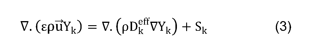
Conservation of species:
Figure imgf000009_0004
where p is the fluid density, u is the fluid velocity vector, p is the fluid pressure, μ is the mixture viscosity, Yk is the mass fraction for gas species k, ε is the porosity of the porous media, Sk is the source or sink term for species k, and Dk ff is the diffusion coefficient of species k and it can be calculated as follow:
Figure imgf000009_0001
where ξ is the tortuosity of the porous media and D is the ordinary diffusion coefficient. Conservation of charge:
Figure imgf000009_0005
Figure imgf000010_0002
where asol is the electric conductivity of solid, amem is the proton conductivity in membrane, 0sol is the potential of solid phase, 0mem is the potential of membrane phase, ]a is cathode catalyst reaction rate and ]c is cathode catalyst reaction rate.
Conservation of liquid water formation:
Figure imgf000010_0003
where S is the liquid water saturation, L is the liquid water and rwis the mass transfer rate between the gas and liquid.
Conservation of energy:
Figure imgf000010_0004
where cp is the specific heat capacity of the gas mixture, T is the temperature, Se is the energy source term and keff is the effective thermal conductivity of the gas mixture which is defined as the follows:
Figure imgf000010_0001
where ks and kF are the thermal conductivities of the solid and fluid regions, respectively.
All the source terms in the above equations are listed in Tablel .
Figure imgf000011_0001
COMPUTATIONAL DOMAIN
A schematic of the 1 1 -channel serpentine flow field of the PEM fuel cell is shown in Figure 1 . Typically, a PEM fuel cell comprises a proton-conducting polymer membrane, (the electrolyte) which separates the anode and cathode sides. On the anode side, hydrogen diffuses to the anode catalyst where it later dissociates into protons and electrons. These protons often react with oxidants causing them to become what is commonly referred to as multi-facilitated proton membranes. The protons are conducted through the membrane to the cathode, but the electrons are forced to travel in an external circuit (supplying power) because the membrane is electrically insulating. On the cathode catalyst, oxygen molecules react with the electrons (which have traveled through the external circuit) and protons to form water— in this example, the only waste product, either liquid or vapor.
The different components of a PEMFC are bipolar plates, electrodes, catalyst, membrane, and the necessary hardwares. The materials used for different parts of the fuel cells differ by type. The bipolar plates may be made of different types of materials, such as, metal, coated metal, graphite, flexible graphite, C-C composite, carbon- polymer composites etc. The membrane electrode assembly (MEA) is usually made of a proton exchange membrane sandwiched between two catalyst coated carbon papers. Platinum and/or similar type of noble metals are usually used as the catalyst for PEMFC. The electrolyte could be a polymer membrane. Merely as an example, the PEM fuel cell dimensions were specified as 32x10.81x32mm in the x, y and z directions, respectively. The 3-D model consisted of nine zones which are: cathode current collector, cathode channel, cathode gas diffusion layer, cathode catalyst layer, membrane, anode catalyst layer, anode gas diffusion layer, anode channel, and anode current collector. 5 meshes were built with different numbers of cells and the average current density at 0.55 V was calculated for these 5 meshes. For the purposes of the example, a mesh which has about 1 ,800,000 control volumes is used to save calculation time and the computing memory to investigate the effect of the anisotropy thermal conductivity of the GDL on the performance of PEM fuel cell. This simulation has been performed by using the fuel cell module in the FLUENT® software.
PHYSICAL AND OPERATING PARAMETERS
The fluid flow in the PEM fuel cell was generated under steady state conditions and all of the governing parameters, at the same values as the experimental parameters, are listed in Table 1. For the purposes of the examples, the velocity at the anode side was set to be 0.42 m/s with fully humidified hydrogen, while the velocity at the cathode channel was 1 .06 m/s with humidified air. Isothermal constant temperature wall boundaries were defined for the cell sides and the current collectors. The operating temperatures were 303K, 313K, 323K, and 333K, respectively. The gauge pressure was set to be 2.5 bar at both the anode and cathode sides. All the physical, geometrical and operational parameters for the example are summarised in table 2 below:
Figure imgf000013_0001
Figure imgf000014_0002
RESULTS AND DISCUSSION
In order to investigate the effect of the anisotropic thermal conductivity of the GDL in PEM fuel cells, nine different cases were developed. The first three cases investigated the effect of the in-plane thermal conductivity and the results are shown in Figures 2 to 5c. The second three cases investigated the effect of the through-plane thermal conductivity and the results are shown in Figures 6 to 10c. The last three investigated the effect of the in-plane thermal conductivity and the results are shown in Figures 10a to 1 1.
The first three cases are summarised below:
Figure imgf000014_0001
In these first three examples, the in-plane thermal conductivity of the GDL was increased from 1 to 10 to 100 W/(m.K). The in-plane thermal conductivity has been reported to be between 10 - 15 W/(m.K) [10] and based on this it has been decided to increase and decrease this value by a factor of 10. The through-plane thermal conductivity of the GDL was retained at a constant value of 1 W/(m.K), namely the reported experimental value [6,10].
Figure 2 shows the polarisation curves which were generated for the different cases and compared with the experimental data for the in-house PEM fuel cell. We observe that the results show good agreement between the experimental data and the case II, where the in-plane thermal conductivity was 10 W/(m.K) and the through-plane thermal conductivity was 1 W/(m.K). As mentioned earlier, this is most likely to be the thermal conductivity values in the experimental investigations.
Figure 3 illustrates the power density of the PEM fuel cell at 0.55 V, which is one of the normal operating voltages of PEM fuel cells. It is clear that as the in-plane thermal conductivity of the GDL increases from 1 to 10 to 100 W/(m.K), the power density of the PEM fuel cell increases from 84.2 to 109.5 to 152.1 mA/cm2, respectively. A similar, though less pronounced effect was found at the higher operating temperatures of the PEM fuel cell of 313 K, 323 K and 333 K.
The effect of the thermal conductivity of the GDL on the power density was because of the decrease in the electrical resistance when the temperature decreases as a result of increasing the thermal conductivity [21 ]. Furthermore, the increased overall thermal conduction of the GDL assists in dissipating the heat from the MEA and consequently these results in a more uniform temperature distribution and having more liquid water to humidify the membrane, which enhances the ionic conductivity, and subsequently improves the performance of the cell [22].
The temperature distribution through the GDL is presented in Figures 4a to 4c. The results show that as the in-plane thermal conductivity of the GDL increases, the difference in the temperatures decreases and the temperature in the GDL becomes more uniform. The maximum temperature was found to be 313.6K when the in-plane thermal conductivity of the GDL was 1 W/(m.K) and the difference in the temperatures was 10K. The maximum temperature decreases to 308.5K when the in-plane thermal conductivity of the GDL increases to 10 W/(m.K) and the difference in the temperatures was 5.5K. Finally, the maximum temperature became 306.1 K when the in-plane thermal conductivity was 100 W/(m.K) and the temperature becomes more uniform along the GDL. The low in-plane thermal conductivity causes regions of the fuel cell to remain relatively cold, thus increasing the likelihood of the formation of water pockets which may block the channels in the PEM fuel cell. This is illustrated in Figures 5a to 5c. It can be seen from Figure 5c that the maximum water saturation was 0.367 when the in-plane thermal conductivity was at its maximum value, namely 100 W/mk. This high water saturation means that more liquid water remains in the cathode because of the low temperature which is caused by the high in-plane thermal conductivity of the GDL [1 1 , 21 ]. This leads to less water, which is produced by the electrochemical reactions in the cell, to vaporize than in the low in-plane thermal conductivity cases [23].
The second three cases are summarised below:
Figure imgf000016_0001
In these second three examples, the effect of the through-plane thermal conductivity was investigated. The through-plane thermal conductivity of the GDL increases from 0.1 to 1 to 10 W/(m.K), while the in-plane thermal conductivity of GDL was kept constant at 10 W/(m.K), the experimental value. The through-plane thermal conductivity was reported to be between 0.1 - 1 W/(m.K) [6,10] and based on this it has been decided to increase and decrease this value by a factor of 10.
Figure 6 shows the polarisation curves obtained from the CFD model compared with the experimental data for the in-house PEM fuel cell. The results show good agreement between the experimental data and case V, which is also Case II in Table 2. Figure 7 illustrates the power density of the PEM fuel cell at 0.55 V, one of the typical operating voltages of PEM fuel cells. As the in-plane thermal conductivity of the GDL increases from 0.1 to 1 to 10 W/(m.K), the power density of the PEM fuel cell increases from 84.1 to 109.5 to 1 19.2 mA/cm2, respectively. This increasing behaviour is also observed at each temperature when the operating temperature of the PEM fuel cell increases from 313K to 323K to 333K. The increased through-plane thermal conductivity assists in decreasing the difference in the temperatures and subsequently less liquid water is evaporated and this improves the performance of the PEM fuel cell.
The effect of the through-plane thermal conductivities of the GDL on the temperature distribution in the PEM fuel cell is illustrated in Figures 8a to 8c. The maximum temperature was found to be 312.4K when the through-plane thermal conductivity of the GDL was 0.1 W/(m.K) and the maximum difference in the temperatures was 9.4K. The maximum temperature reduces to 308.5K when the through-plane thermal conductivity of the GDL increases to 1 W/(m.K) and the maximum difference in the temperatures was 5.5K. Finally, the maximum temperature became 305.9K when the in-plane thermal conductivity was 10 W/(m.K), the temperature became more uniform along the GDL, and the difference in the temperatures was no more than 2.9K. This is because the increase in the heat removal within the GDL assists in producing a more uniform temperature distribution [22].
It can be seen from Figures 9a to 9c that the maximum water saturation was 0.371 when the through-plane thermal conductivity was a maximum, namely 10 W/(m.K). This high water saturation means that more liquid water remains in the cathode because of the low temperature which is caused by the high in-plane thermal conductivity of the GDL. This water saturation reduces to 0.355 when the through- plane thermal conductivity of the GDL was reduced to 0.1 W/(m.K).
Another three cases are summarised below:
Figure imgf000017_0001
In this study, as set out above, a three-dimensional (3-D) model was developed under steady state conditions. In this case; the velocity at the anode side was 0.24 m/s with fully humidified hydrogen, while the velocity at the cathode channel was 1 .06 m/s with humidified air. The thermal wall boundaries were defined for the cell sides and the current collectors. The in-plane thermal conductivity of the GDL increased slightly, while the through-plane thermal conductivity of the GDL kept constant at 1 (W/(m.K). As shown in Figures 10a to 10c, the temperature decreased when the in-plane thermal conductivity was increased, and the temperature was higher under the channel regions than in the current collector regions. The maximum temperatures were 306.6 K, 305.2K and 304.0 K for 1 (W/(m.K)), 10 (W/(m.K)) and 20 (W/(m.K)) in-plane thermal conductivity, respectively.
As shown in Figure 1 1 , the overall performance of the PEM fuel cell increased when the in-plane thermal conductivity of the GDL increased. Conclusions
A 3-D multiphase model has been developed to investigate the effect of the anisotropic thermal conductivity of the GDL on the performance of PEM fuel cells, and the results have been validated with an in-house PEM fuel cell. It has been found that the maximum temperature in the PEM fuel cell decreases when the thermal conductivity increases under the operating conditions investigated. In addition, the difference in the temperatures decreases when increasing the in-plane and through-plane thermal conductivities. The results show an increase in the current density of PEM fuel cells with an increase in the thermal conductivity of the GDL in both directions, namely the in-plane and the through-plane. This is the situation for all of the different operating temperatures that have been investigated (303K, 313K, 323K, and 333K). Moreover, increasing the thermal conductivity of the GDL increases the liquid water saturation as the maximum temperature decreases. This study has highlighted the need to accurately determine the thermal conductivity of the GDL. NOMENCLATURE
Figure imgf000018_0001
Figure imgf000019_0001
REFERENCES
1. Barbir F., (201 1 ) Pern Fuel Cells: Theory and Practice. Elsevier Science & Technology.
2. Hoogers G. , (2003) Fuel cell technology handbook. CRC Press.
3. Blomen L. J. ,M.J. and Mugerwa M.N. , (1993) Fuel cell systems. Plenum Press.
4. Larminie J. and Dicks A. , (2000) Fuel cell systems explained. Wiley.
5. Basu S. , (2006) Recent trends in fuel cell science and technology. Springer.
6. Khandelwal M. and Mench M. , (2006) Direct measurement of through-plane thermal conductivity and contact resistance in fuel cell materials. Journal of Power Sources, 161 , pp. 1 106-1 1 15.
7. Ramousse J., Lottin O., Didierjean S., Maillet D., (2009) Heat sources in proton exchange membrane (PEM) fuel cells. Journal of Power Sources, 192, pp. 435-
41 .
8. Karimi G., Li X. and TeertstraP. , (2010) Measurement of through-plane effective thermal conductivity and contact resistance in PEM fuel cell diffusion media. Electrochimica Acta 55, pp. 1619-1625. Pharaoh J.G. and Burheim O.S. , (2010) On the temperature distribution in polymer electrolyte fuel cells. Journal of Power Sources, 195, pp. 5235-5245. Zamel N., Li x., Shen J., Wiegmann A., Becker J., (2010) Estimating effective thermal conductivity in carbon paper diffusion media. Chemical Engineering Science, 65, pp. 3994-4006.
Burlatsky S., Atrazhev V., Gummalla M., Liu F.,(2009) The impact of thermal conductivity and diffusion rates on water vapor transport through gas diffusion layers. Journal of Power Sources, 190, pp. 485-492.
He G., Yamazaki Y. and Abudula A. , (2010) A three-dimensional analysis of the effect of anisotropic gas diffusion layer (GDL) thermal conductivity on the heat transfer and two-phase behavior in a proton exchange membrane fuel cell (PEMFC). Journal of Power Sources, 195, pp. 1551 -1560.
Ma L., Inghham D. B., Pourkashanian M., (2005) Review of the computational fluid dynamics modeling of fuel cells. Journal of Fuel Cell Science and Technology, 2, pp. 246-257.
Bernardi D. M. and M. W. Verbrugge, A Mathematical Model of the Solid Polymer Electrolyte Fuel Cell. Journal of the Electrochemical Society, 1992.139(9): p. 2477-2491.
P.M. Wilde, M.M., M. Murata, and N. Berg, Structural and Physical Properties of GDL and GDL/BPP Combinations and their Influence on PEMFC Performance. Fuel Cells, 2004. 4(3): p. 180-184.
Ismail M.S., Damjanovicb T. , Inghama D.B. , Ma L., Pourkashaniana M. , Effect of polytetrafluoroethylene-treatment and microporous layer-coating on the in- plane permeability of gas diffusion layers used in proton exchange membrane fuel cells. Journal of Power Sources, 2010. 195(19): p. 6619-6628.
Ismail M.S., by M S Ismail, T Damjanovic, D B Ingham, M Pourkashanian, A Westwood, Effect of polytetrafluoroethylene-treatment and microporous layer- coating on the electrical conductivity of gas diffusion layers used in proton exchange membrane fuel cells. Journal of Power Sources, 2010. 195(9): p. 2700-2708.
Kim , G.-S., Sui, P. C, Shah, A. A., Djilali, Ned, Reduced-dimensional models for straight-channel proton exchange membrane fuel cells. Journal of Power Sources. 195(10): p. 3240-3249. Cheng C, H. Lin, and G J. Lai, Numerical prediction of the effect of catalyst layer Nafion loading on the performance of PEM fuel cells. Journal of Power Sources, 2007. 164(2): p. 730-741.
ANSAYS Fluent, "Fuel cell modueles manual," Lebanon, New Hampshire (USA) Fluent Inc, 2010.
Tritt, T.M., Thermal conductivity: theory, properties, and applications. 2004: Kluwer Academic/Plenum Publishers.
Meng H., Numerical studies of liquid water behaviors in PEM fuel cell cathode considering transport across different porous layers. International Journal of Hydrogen Energy, 2010. 35: p. 5569-5579.
Gostick T., loannidis A., Pritzker D., and Fowler W., Impact of liquid water on reactant mass transfer in PEM fuel cell electrodes. Journal of the Electrochemical Society, 2010. 157: p. B563-B571 .
Ju H., Investigation of the effects of the anisotropy of gas-diffusion layers on heat and water transport in polymer electrolyte fuel cells. Journal of Power Sources, 2009. 191 (2): p. 259-268
No doubt many other effective alternatives will occur to the skilled person. It will be understood that the invention is not limited to the described embodiments and encompasses modifications apparent to those skilled in the art lying within the spirit and scope of the claims appended hereto.

Claims

CLAIMS:
1 . A method of designing a proton exchange membrane fuel cell comprising a gas diffusion layer, the method comprising:
using a model of the proton exchange membrane fuel cell to determine performance of said fuel cell, wherein said model is based on a plurality of parameters of the fuel cell, said plurality of parameters including at least one anisotropic property of the gas diffusion layer,
adjusting at least one of the plurality of parameters;
determining whether or not performance of the fuel cell is improved by said adjusting step and
designing said fuel cell by selecting said parameters which provide improved performance.
2. A method according to claim 1 comprising using said model to determine performance by determining one or more of temperature distribution, water saturation, and/or current density of the fuel cell.
3. A method according to claim 2, wherein the performance is improved by providing a more uniform temperature distribution across the gas diffusion layer.
4. A method according to any one of the preceding claims wherein the model comprises multiple zones defined within the fuel cell.
5. A method according to claim 4, wherein said multiple zones comprise one or more of a current collector, a channel, a gas diffusion layer, a catalyst layer and said membrane.
6. A method according to claim 5, wherein the fuel cell comprises an anode and a cathode and wherein separate zones are defined for each of said anode and said cathode.
7. A method according to any one of the preceding claims comprising making a fuel cell to said design whereby said modelled performance is validated with the experimental data.
8. A method according to any one of the preceding claims, wherein the plurality of parameters include the material of the gas diffusion layer (GDL).
9. A method according to any one of the preceding claims, wherein the anisotropic properties include one or more of the electrical conductivity, thermal conductivity, and/or permeability of the gas diffusion layer.
10. A method according to claim 9, wherein the thermal conductivity includes in- plane thermal conductivity and/or through plane thermal conductivity.
1 1 . A proton exchange membrane fuel cell comprising a gas diffusion layer, said proton exchange membrane fuel cell having a plurality of parameters, wherein said parameters are selected to provide substantially uniform temperature distribution across said gas diffusion layer.
12. A fuel cell according to claim 1 1 , wherein the parameters include thermal conductivity of the gas diffusion layer, including in-plane thermal conductivity and/or through-plane thermal conductivity of the gas diffusion layer is substantially isotropic.
13. A fuel cell according to claim 12, wherein the gas diffusion has an in-plane thermal conductivity of at least 10 W/(m.K) or at least 100 W/(m.K).
14. A fuel cell according to claim 1 1 or claim 12, wherein the gas diffusion has a through-plane thermal conductivity of the gas diffusion layer is at least 1 W/(m.K) or at least 10 W/(m.K).
15. A fuel cell according to any one of claims 1 1 to 14, wherein the gas diffusion layer has an in-plane thermal conductivity of at least 10 W/(m.K) and a through-plane thermal conductivity of at least 1 W/(m.K).
16. A fuel cell comprising a proton exchange membrane having a gas diffusion layer, wherein the thermal conductivity of the gas diffusion layer is substantially isotropic.
17. A fuel cell comprising a proton exchange membrane having a gas diffusion layer, wherein the in-plane thermal conductivity of the gas diffusion layer is substantially isotropic.
18. A fuel cell comprising a proton exchange membrane having a gas diffusion layer, wherein the through-plane thermal conductivity of the gas diffusion layer is substantially isotropic.
19. A fuel cell comprising a proton exchange membrane having a gas diffusion layer, wherein the gas diffusion layer has an in-plane thermal conductivity of at least 10
W/(m.K).
20. A fuel cell as claimed in claim 19, wherein the in-plane thermal conductivity of the gas diffusion layer is at least 100 W/(m.K).
21 . A fuel cell as claimed in claim 20, wherein the in-plane thermal conductivity of the gas diffusion layer is at least 200 W(m.K).
22. A fuel cell as claimed in claim 21 , wherein the in-plane thermal conductivity of the gas diffusion layer is at least 400 W(m.K).
23. A fuel cell comprising a proton exchange membrane having a gas diffusion layer, wherein the through-plane thermal conductivity of the gas diffusion layer is at least 1 W/(m.K).
24. A fuel cell comprising a proton exchange membrane having a gas diffusion layer, wherein the through-plane thermal conductivity of the gas diffusion layer is at least 10 W/(m.K).
25. A fuel cell comprising a proton exchange membrane having a gas diffusion layer, wherein the gas diffusion layer has an in-plane thermal conductivity of at least 10 W/(m.K) and a through-plane thermal conductivity of at least 1 W/(m.K).
26. A fuel cell as claimed in any preceding claim, wherein the gas diffusion layer is metallic.
27. A fuel cell proton exchange membrane having a gas diffusion layer substantially as claimed in any preceding claim.
28. A fuel cell proton exchange membrane gas diffusion layer substantially as claimed in any preceding claim.
29. A method of making a fuel cell comprising a proton exchange membrane having a gas diffusion layer, comprising the step of arranging the thermal conductivity of the gas diffusion layer in the in-plane and/or through-plane directions to be substantially isotropic
PCT/GB2012/053050 2011-12-13 2012-12-07 Proton exchange membrane fuel cell WO2013088122A1 (en)

Priority Applications (5)

Application Number Priority Date Filing Date Title
CN201280061885.5A CN104040772A (en) 2011-12-13 2012-12-07 Proton exchange membrane fuel cell
KR1020147019442A KR20140112023A (en) 2011-12-13 2012-12-07 Proton exchange membrane fuel cell
EP12806629.7A EP2792011A1 (en) 2011-12-13 2012-12-07 Proton exchange membrane fuel cell
US14/365,124 US20140370416A1 (en) 2011-12-13 2012-12-07 Proton exchange membrane fuel cell
JP2014546627A JP2015505132A (en) 2011-12-13 2012-12-07 Proton exchange membrane fuel cell

Applications Claiming Priority (2)

Application Number Priority Date Filing Date Title
GB1121394.9 2011-12-13
GBGB1121394.9A GB201121394D0 (en) 2011-12-13 2011-12-13 Proton exchange membrane fuel cell

Publications (1)

Publication Number Publication Date
WO2013088122A1 true WO2013088122A1 (en) 2013-06-20

Family

ID=45560374

Family Applications (1)

Application Number Title Priority Date Filing Date
PCT/GB2012/053050 WO2013088122A1 (en) 2011-12-13 2012-12-07 Proton exchange membrane fuel cell

Country Status (7)

Country Link
US (1) US20140370416A1 (en)
EP (1) EP2792011A1 (en)
JP (1) JP2015505132A (en)
KR (1) KR20140112023A (en)
CN (1) CN104040772A (en)
GB (1) GB201121394D0 (en)
WO (1) WO2013088122A1 (en)

Cited By (12)

* Cited by examiner, † Cited by third party
Publication number Priority date Publication date Assignee Title
EP3145012A1 (en) * 2015-09-21 2017-03-22 Commissariat à l'énergie atomique et aux énergies alternatives Determination of a spatial distribution of the permeability of an electrochemical cell electrode
US10162012B2 (en) 2015-09-21 2018-12-25 Commissariat A L'energie Atomique Et Aux Energies Alternatives Determining of a spatial distribution of the electrical contact resistance of an electrochemical cell
US10181612B2 (en) 2015-09-21 2019-01-15 Commissariat A L'energie Atomique Et Aux Energies Alternatives Determination of a spatial distribution of the catalytic activity of an electrochemical-cell electrode
US10446858B2 (en) 2014-10-07 2019-10-15 Upstart Power, Inc. SOFC-conduction
US10573911B2 (en) 2015-10-20 2020-02-25 Upstart Power, Inc. SOFC system formed with multiple thermally conductive pathways
CN111079337A (en) * 2019-12-23 2020-04-28 畔星科技(浙江)有限公司 Multi-physical-field coupling simulation method for proton exchange membrane fuel cell
US10686202B2 (en) 2015-09-21 2020-06-16 Commissariat A L'energie Atomique Et Aux Energies Alternatives Determination of a spatial distribution of an electrical production parameter of an electrochemical cell
US10790523B2 (en) 2015-10-20 2020-09-29 Upstart Power, Inc. CPOX reactor control system and method
US11108072B2 (en) 2016-08-11 2021-08-31 Upstart Power, Inc. Planar solid oxide fuel unit cell and stack
CN114965585A (en) * 2022-06-29 2022-08-30 清华大学 Method, device, equipment, medium and product for evaluating quality of membrane electrode catalyst layer
US11658323B2 (en) 2019-09-30 2023-05-23 King Fahd University Of Petroleum And Minerals Method for making a hydrogen fuel cell gas diffusion layer having tailored porosity
US11984630B2 (en) 2023-05-02 2024-05-14 King Fahd University Of Petroleum And Minerals Method for producing electricity from a hydrogen fuel cell

Families Citing this family (13)

* Cited by examiner, † Cited by third party
Publication number Priority date Publication date Assignee Title
JP6515326B2 (en) * 2015-03-10 2019-05-22 パナソニックIpマネジメント株式会社 Fuel cell simulation method and simulation apparatus
CN106960970B (en) * 2017-02-23 2019-09-03 天津大学 Proton Exchange Membrane Fuel Cells internal water distribution forecasting method
WO2018235108A1 (en) * 2017-06-19 2018-12-27 Politecnico Di Milano Locally engineered pem cells components with optimized operation for improved durability
DE102017127276A1 (en) * 2017-08-30 2019-02-28 Taiwan Semiconductor Manufacturing Co., Ltd. STANDARD CELLS AND ADAPTATIONS FROM THEREOF WITHIN A STANDARD CELL LIBRARY
JP7052418B2 (en) * 2018-03-01 2022-04-12 トヨタ自動車株式会社 Gas diffusion layer
CN111028894B (en) * 2019-11-22 2023-06-23 华中科技大学鄂州工业技术研究院 Method for determining optimal efficiency of electrolytic cell based on two-dimensional steady-state model
CN112993336B (en) * 2019-12-14 2022-04-22 中国科学院大连化学物理研究所 Water management fault diagnosis method for vehicle fuel cell attenuation process
CN112507526B (en) * 2020-11-20 2022-04-15 武汉船用电力推进装置研究所(中国船舶重工集团公司第七一二研究所) Performance prediction method and system for proton exchange fuel cell system
CN112582635B (en) * 2020-12-09 2022-04-29 南京航空航天大学 Method for optimizing PEMFC bipolar plate flow channel section and three-dimensional proton exchange membrane fuel cell
CN113555588A (en) * 2021-07-13 2021-10-26 广东兰氢科技有限公司 Fuel cell performance prediction method and device, electronic equipment and storage medium
CN113889646B (en) * 2021-09-23 2023-09-22 中汽创智科技有限公司 Performance analysis method, device, equipment and storage medium for fuel cell catalytic layer
CN114006009B (en) * 2021-10-14 2023-05-26 西安交通大学 Modeling method of proton exchange membrane fuel cell coupled with agglomeration of catalytic layer
CN114976133B (en) * 2022-06-30 2024-04-02 浙江大学 Model-based proton exchange membrane fuel cell water management fault tolerance control method

Citations (2)

* Cited by examiner, † Cited by third party
Publication number Priority date Publication date Assignee Title
WO2009038577A1 (en) * 2007-09-19 2009-03-26 Utc Power Corporation High thermal conductivity electrode substrate
US7785748B2 (en) 2006-04-03 2010-08-31 University Of Delaware Nano-based gas diffusion media

Family Cites Families (1)

* Cited by examiner, † Cited by third party
Publication number Priority date Publication date Assignee Title
CN102082277B (en) * 2010-12-24 2013-06-19 上海交通大学 Metal gas diffusion layer used for fuel cell and preparation method thereof

Patent Citations (2)

* Cited by examiner, † Cited by third party
Publication number Priority date Publication date Assignee Title
US7785748B2 (en) 2006-04-03 2010-08-31 University Of Delaware Nano-based gas diffusion media
WO2009038577A1 (en) * 2007-09-19 2009-03-26 Utc Power Corporation High thermal conductivity electrode substrate

Non-Patent Citations (25)

* Cited by examiner, † Cited by third party
Title
ANSAYS FLUENT: "Fuel cell modueles manual", 2010, FLUENT INC
BARBIR F.: "Pem Fuel Cells: Theory and Practice", 2011, ELSEVIER SCIENCE & TECHNOLOGY
BASU S.: "Recent trends in fuel cell science and technology", 2006, SPRINGER
BERNARDI D. M.; M. W. VERBRUGGE: "A Mathematical Model of the Solid Polymer Electrolyte Fuel Cell", JOURNAL OF THE ELECTROCHEMICAL SOCIETY, vol. 139, no. 9, 1992, pages 2477 - 2491, XP055269541, DOI: doi:10.1149/1.2221251
BLOMEN L. J.; M.J.; MUGERWA M.N.: "Fuel cell systems", 1993, PLENUM PRESS
BURLATSKY S.; ATRAZHEV V.; GUMMALLA M.; LIU F.: "The impact of thermal conductivity and diffusion rates on water vapor transport through gas diffusion layers", JOURNAL OF POWER SOURCES, vol. 190, 2009, pages 485 - 492, XP026130398, DOI: doi:10.1016/j.jpowsour.2008.12.131
CHENG C.; H. LIN; G J. LAI: "Numerical prediction of the effect of catalyst layer Nafion loading on the performance of PEM fuel cells", JOURNAL OF POWER SOURCES, vol. 164, no. 2, 2007, pages 730 - 741, XP005737126, DOI: doi:10.1016/j.jpowsour.2006.11.039
GOSTICK T.; LOANNIDIS A.; PRITZKER D.; FOWLER W.: "Impact of liquid water on reactant mass transfer in PEM fuel cell electrodes", JOURNAL OF THE ELECTROCHEMICAL SOCIETY, vol. 157, 2010, pages B563 - B571
HE G.; YAMAZAKI Y.; ABUDULA A.: "A three-dimensional analysis of the effect of anisotropic gas diffusion layer (GDL) thermal conductivity on the heat transfer and two-phase behavior in a proton exchange membrane fuel cell (PEMFC", JOURNAL OF POWER SOURCES, vol. 195, 2010, pages 1551 - 1560, XP026761948, DOI: doi:10.1016/j.jpowsour.2009.09.059
HOOGERS G.: "Fuel cell technology handbook", 2003, CRC PRESS
ISMAIL M.S.; DAMJANOVICB T.; INGHAMA D.B.; MA L.; POURKASHANIANA M.: "Effect of polytetrafluoroethylene-treatment and microporous layer-coating on the in-plane permeability of gas diffusion layers used in proton exchange membrane fuel cells", JOURNAL OF POWER SOURCES, vol. 195, no. 19, 2010, pages 6619 - 6628, XP027074543, DOI: doi:10.1016/j.jpowsour.2010.04.036
ISMAIL M.S.; M S ISMAIL; T DAMJANOVIC; D B INGHAM; M POURKASHANIAN; A WESTWOOD: "Effect of polytetrafluoroethylene-treatment and microporous layer-coating on the electrical conductivity of gas diffusion layers used in proton exchange membrane fuel cells", JOURNAL OF POWER SOURCES, vol. 195, no. 9, 2010, pages 2700 - 2708, XP026827307
JU H.: "Investigation of the effects of the anisotropy of gas-diffusion layers on heat and water transport in polymer electrolyte fuel cells", JOURNAL OF POWER SOURCES, vol. 191, no. 2, 2009, pages 259 - 268, XP026100391, DOI: doi:10.1016/j.jpowsour.2009.01.103
KARIMI G.; LI X.; TEERTSTRAP.: "Measurement of through-plane effective thermal conductivity and contact resistance in PEM fuel cell diffusion media", ELECTROCHIMICA ACTA, vol. 55, 2010, pages 1619 - 1625, XP026874962
KHANDELWAL M.; MENCH M.: "Direct measurement of through-plane thermal conductivity and contact resistance in fuel cell materials", JOURNAL OF POWER SOURCES, vol. 161, 2006, pages 1106 - 1115, XP025084903, DOI: doi:10.1016/j.jpowsour.2006.06.092
KIM , G.-S.; SUI, P. C.; SHAH, A. A.; DJILALI, NED: "Reduced-dimensional models for straight-channel proton exchange membrane fuel cells", JOURNAL OF POWER SOURCES, vol. 195, no. 10, pages 3240 - 3249, XP026854804
LARMINIE J.; DICKS A.: "Fuel cell systems explained", 2000, WILEY
MA L.; INGHHAM D. B.; POURKASHANIAN M.: "Review of the computational fluid dynamics modeling of fuel cells", JOURNAL OF FUEL CELL SCIENCE AND TECHNOLOGY, vol. 2, 2005, pages 246 - 257
MENG H.: "Numerical studies of liquid water behaviors in PEM fuel cell cathode considering transport across different porous layers", INTERNATIONAL JOURNAL OF HYDROGEN ENERGY, vol. 35, 2010, pages 5569 - 5579, XP027060162
P.M. WILDE; M.M.; M. MURATA; N. BERG: "Structural and Physical Properties of GDL and GDL/BPP Combinations and their Influence on PEMFC Performance", FUEL CELLS, vol. 4, no. 3, 2004, pages 180 - 184
PHARAOH J.G.; BURHEIM O.S.: "On the temperature distribution in polymer electrolyte fuel cells", JOURNAL OF POWER SOURCES, vol. 195, 2010, pages 5235 - 5245
PHAROAH J G ET AL: "On the temperature distribution in polymer electrolyte fuel cells", JOURNAL OF POWER SOURCES, ELSEVIER SA, CH, vol. 195, no. 16, 15 August 2010 (2010-08-15), pages 5235 - 5245, XP027015183, ISSN: 0378-7753, [retrieved on 20100419] *
RAMOUSSE J.; LOTTIN O.; DIDIERJEAN S.; MAILLET D.: "Heat sources in proton exchange membrane (PEM) fuel cells", JOURNAL OF POWER SOURCES, vol. 192, 2009, pages 435 - 41, XP026140123, DOI: doi:10.1016/j.jpowsour.2009.03.038
TRITT, T.M.: "Thermal conductivity: theory, properties, and applications", 2004, KLUWER ACADEMIC/PLENUM PUBLISHERS
ZAMEL N.; LI X.; SHEN J.; WIEGMANN A.; BECKER J.: "Estimating effective thermal conductivity in carbon paper diffusion media", CHEMICAL ENGINEERING SCIENCE, vol. 65, 2010, pages 3994 - 4006, XP027061590

Cited By (20)

* Cited by examiner, † Cited by third party
Publication number Priority date Publication date Assignee Title
US10916784B2 (en) 2014-10-07 2021-02-09 Upstart Power, Inc. SOFC-conduction
US10446858B2 (en) 2014-10-07 2019-10-15 Upstart Power, Inc. SOFC-conduction
US11784331B2 (en) 2014-10-07 2023-10-10 Upstart Power, Inc. SOFC-conduction
FR3041478A1 (en) * 2015-09-21 2017-03-24 Commissariat Energie Atomique DETERMINING A SPATIAL DISTRIBUTION OF THE PERMEABILITY OF AN ELECTROCHEMICAL CELL ELECTRODE
US10162012B2 (en) 2015-09-21 2018-12-25 Commissariat A L'energie Atomique Et Aux Energies Alternatives Determining of a spatial distribution of the electrical contact resistance of an electrochemical cell
US10181612B2 (en) 2015-09-21 2019-01-15 Commissariat A L'energie Atomique Et Aux Energies Alternatives Determination of a spatial distribution of the catalytic activity of an electrochemical-cell electrode
EP3145012A1 (en) * 2015-09-21 2017-03-22 Commissariat à l'énergie atomique et aux énergies alternatives Determination of a spatial distribution of the permeability of an electrochemical cell electrode
US10651483B2 (en) 2015-09-21 2020-05-12 Commissariat A L'energie Atomique Et Aux Energies Alternatives Determination of a spatial distribution of the permeability of an electrochemical - cell electrode
US10686202B2 (en) 2015-09-21 2020-06-16 Commissariat A L'energie Atomique Et Aux Energies Alternatives Determination of a spatial distribution of an electrical production parameter of an electrochemical cell
US10573911B2 (en) 2015-10-20 2020-02-25 Upstart Power, Inc. SOFC system formed with multiple thermally conductive pathways
US10790523B2 (en) 2015-10-20 2020-09-29 Upstart Power, Inc. CPOX reactor control system and method
US11605825B2 (en) 2015-10-20 2023-03-14 Upstart Power, Inc. CPOX reactor control system and method
US11108072B2 (en) 2016-08-11 2021-08-31 Upstart Power, Inc. Planar solid oxide fuel unit cell and stack
US11664517B2 (en) 2016-08-11 2023-05-30 Upstart Power, Inc. Planar solid oxide fuel unit cell and stack
US11658323B2 (en) 2019-09-30 2023-05-23 King Fahd University Of Petroleum And Minerals Method for making a hydrogen fuel cell gas diffusion layer having tailored porosity
US11978936B2 (en) 2019-09-30 2024-05-07 King Fahd University Of Petroleum And Minerals Hydrogen membrane fuel cell with electrode assembly
CN111079337B (en) * 2019-12-23 2023-09-01 畔星科技(浙江)有限公司 Multi-physical field coupling simulation method for proton exchange membrane fuel cell
CN111079337A (en) * 2019-12-23 2020-04-28 畔星科技(浙江)有限公司 Multi-physical-field coupling simulation method for proton exchange membrane fuel cell
CN114965585A (en) * 2022-06-29 2022-08-30 清华大学 Method, device, equipment, medium and product for evaluating quality of membrane electrode catalyst layer
US11984630B2 (en) 2023-05-02 2024-05-14 King Fahd University Of Petroleum And Minerals Method for producing electricity from a hydrogen fuel cell

Also Published As

Publication number Publication date
US20140370416A1 (en) 2014-12-18
JP2015505132A (en) 2015-02-16
CN104040772A (en) 2014-09-10
KR20140112023A (en) 2014-09-22
EP2792011A1 (en) 2014-10-22
GB201121394D0 (en) 2012-01-25

Similar Documents

Publication Publication Date Title
WO2013088122A1 (en) Proton exchange membrane fuel cell
Neidhardt et al. A flexible framework for modeling multiple solid, liquid and gaseous phases in batteries and fuel cells
Alhazmi et al. Effect of the anisotropic thermal conductivity of GDL on the performance of PEM fuel cells
Ota et al. Object-based modeling of SOFC system: dynamic behavior of micro-tube SOFC
Ju et al. Nonisothermal modeling of polymer electrolyte fuel cells: I. Experimental validation
Balliet et al. Cold start of a polymer-electrolyte fuel cell i. development of a two-dimensional model
Li et al. Influence of anisotropic gas diffusion layers on transport phenomena in a proton exchange membrane fuel cell
Tzelepis et al. A review study on proton exchange membrane fuel cell electrochemical performance focusing on anode and cathode catalyst layer modelling at macroscopic level
Machado et al. Influences of flow direction, temperature and relative humidity on the performance of a representative anion exchange membrane fuel cell: A computational analysis
Jian et al. Influences of gas relative humidity on the temperature of membrane in PEMFC with interdigitated flow field
Falcão et al. Water transport through a PEM fuel cell: A one-dimensional model with heat transfer effects
Wang et al. Optimization of reactants relative humidity for high performance of polymer electrolyte membrane fuel cells with co-flow and counter-flow configurations
Rakhshanpouri et al. Water transport through a PEM (proton exchange membrane) fuel cell in a seven-layer model
Ho et al. Modeling of transport, chemical and electrochemical phenomena in a cathode-supported SOFC
Oliveira et al. Water management in a passive direct methanol fuel cell
Ly et al. Asymptotically reduced model for a proton exchange membrane fuel cell stack: Automated model generation and verification
Obayopo et al. Three‐dimensional optimisation of a fuel gas channel of a proton exchange membrane fuel cell for maximum current density
Wang Porous-media flow fields for polymer electrolyte fuel cells: I. Low humidity operation
Chinda et al. A planar anode-supported Solid Oxide Fuel Cell model with internal reforming of natural gas
Calili et al. A dynamic model of air-breathing polymer electrolyte fuel cell (PEFC): A parametric study
Afshari et al. Effect of water phase change on temperature distribution in proton exchange membrane fuel cells
Selvaraj et al. Effect of flow fields and humidification of reactant and oxidant on the performance of scaled‐up PEM‐FC using CFD code
Sauermoser et al. The impact of Peltier and Dufour coefficients on heat fluxes and temperature profiles in the polymer electrolyte fuel cells
Severson et al. Modeling of overpotentials in an anode-supported planar SOFC using a detailed simulation model
Jourdani et al. Temperature distribution effect on the performance of PEM Fuel cell modeling and simulation using Ansys Fluent

Legal Events

Date Code Title Description
121 Ep: the epo has been informed by wipo that ep was designated in this application

Ref document number: 12806629

Country of ref document: EP

Kind code of ref document: A1

ENP Entry into the national phase

Ref document number: 2014546627

Country of ref document: JP

Kind code of ref document: A

NENP Non-entry into the national phase

Ref country code: DE

WWE Wipo information: entry into national phase

Ref document number: 14365124

Country of ref document: US

WWE Wipo information: entry into national phase

Ref document number: 2012806629

Country of ref document: EP

ENP Entry into the national phase

Ref document number: 20147019442

Country of ref document: KR

Kind code of ref document: A