WO2013085098A1 - 무회전 ct 시스템 - Google Patents
무회전 ct 시스템 Download PDFInfo
- Publication number
- WO2013085098A1 WO2013085098A1 PCT/KR2012/000123 KR2012000123W WO2013085098A1 WO 2013085098 A1 WO2013085098 A1 WO 2013085098A1 KR 2012000123 W KR2012000123 W KR 2012000123W WO 2013085098 A1 WO2013085098 A1 WO 2013085098A1
- Authority
- WO
- WIPO (PCT)
- Prior art keywords
- ray
- image
- generator
- guide
- rays
- Prior art date
- Legal status (The legal status is an assumption and is not a legal conclusion. Google has not performed a legal analysis and makes no representation as to the accuracy of the status listed.)
- Ceased
Links
Images




Classifications
-
- A—HUMAN NECESSITIES
- A61—MEDICAL OR VETERINARY SCIENCE; HYGIENE
- A61B—DIAGNOSIS; SURGERY; IDENTIFICATION
- A61B6/00—Apparatus or devices for radiation diagnosis; Apparatus or devices for radiation diagnosis combined with radiation therapy equipment
- A61B6/02—Arrangements for diagnosis sequentially in different planes; Stereoscopic radiation diagnosis
- A61B6/03—Computed tomography [CT]
- A61B6/032—Transmission computed tomography [CT]
- A61B6/035—Mechanical aspects of CT
-
- A—HUMAN NECESSITIES
- A61—MEDICAL OR VETERINARY SCIENCE; HYGIENE
- A61B—DIAGNOSIS; SURGERY; IDENTIFICATION
- A61B6/00—Apparatus or devices for radiation diagnosis; Apparatus or devices for radiation diagnosis combined with radiation therapy equipment
- A61B6/02—Arrangements for diagnosis sequentially in different planes; Stereoscopic radiation diagnosis
- A61B6/03—Computed tomography [CT]
-
- A—HUMAN NECESSITIES
- A61—MEDICAL OR VETERINARY SCIENCE; HYGIENE
- A61B—DIAGNOSIS; SURGERY; IDENTIFICATION
- A61B6/00—Apparatus or devices for radiation diagnosis; Apparatus or devices for radiation diagnosis combined with radiation therapy equipment
- A61B6/02—Arrangements for diagnosis sequentially in different planes; Stereoscopic radiation diagnosis
- A61B6/03—Computed tomography [CT]
- A61B6/032—Transmission computed tomography [CT]
-
- A—HUMAN NECESSITIES
- A61—MEDICAL OR VETERINARY SCIENCE; HYGIENE
- A61B—DIAGNOSIS; SURGERY; IDENTIFICATION
- A61B6/00—Apparatus or devices for radiation diagnosis; Apparatus or devices for radiation diagnosis combined with radiation therapy equipment
- A61B6/40—Arrangements for generating radiation specially adapted for radiation diagnosis
- A61B6/4007—Arrangements for generating radiation specially adapted for radiation diagnosis characterised by using a plurality of source units
- A61B6/4014—Arrangements for generating radiation specially adapted for radiation diagnosis characterised by using a plurality of source units arranged in multiple source-detector units
Definitions
- the present invention relates to a CT system that does not require the rotation of a target object or equipment during CT imaging, and relates to a non-rotating CT system including a plurality of X-ray generators and X-ray detectors.
- a computerized tomography (CT) device transmits a certain amount of X-ray flux in a line to a body imaging site, and acquires a change in the X-ray intensity through which the X-ray detector transmits the X-ray absorption rate of each point in the body imaging site. Obtain and reconstruct this into an image.
- CT computerized tomography
- Conventional X-ray CT device uses one or two sources and detectors to rotate an object or sources and detectors around an object to obtain a two-dimensional X-ray image at various angles and then converts it into a CT image. Go through the process.
- the present invention has been made in view of the above point, and after obtaining an X-ray image of various objects every moment for a certain point of time, using the minimum number of two-dimensional X-ray images and image interpolation techniques obtained It is an object of the present invention to provide a non-rotating CT system that can build a CT image for every point of the object.
- Rotationless CT system provided to achieve the above object is a plurality of X-ray generating unit which is disposed radially and spaced apart at regular intervals about the subject to be provided with a position correction sensor on one side; A plurality of X-ray detectors disposed in spaced spaces between the X-ray generators, alternately installed with the X-ray generator, and provided with a position correction sensor on one side; And a controller configured to receive signals from the position correction sensor provided in the X-ray generator and the X-ray detector to adjust the positions of the respective X-ray generators and the X-ray detectors to face each other. do.
- an X-ray guide is provided at one side of the X-ray generating unit toward the inspected object.
- one side of the X-ray detection unit is provided with an X-ray guide toward the object to be inspected, and the X-rays generated by the X-ray generation unit facing forward face the X-rays only to the designated X-ray detection unit after passing through the object. It is preferable.
- the X-ray guide of the X-ray generator and the X-ray detector is preferably composed of an X-ray hygroscopic material, and K ⁇ X-rays function to prevent mutual interference between the K- and K ⁇ -characteristic X-rays at the ends of the X-ray guide of the X-ray generator. It is preferable that a filter is provided, and an elastic scattering prevention filter is provided at the end of the X-ray guide of the X-ray detection unit.
- control unit receives the signal of the position correction sensor so that the X-rays generated from one X-ray generating unit can be transmitted only to the X-ray detection unit designated to face each X-ray generating unit after passing through the subject. It is preferable to adjust the position and direction of the X-ray generator and the X-ray detector.
- Rotationless CT system provided to achieve the above object is a radially spaced at a predetermined interval centering on the inspected object and a plurality of X-ray generating unit provided with a position correction sensor on one side; A plurality of X-ray detectors disposed in spaced spaces between the X-ray generators, alternately installed with the X-ray generator, and provided with a position correction sensor on one side; A control unit that receives signals from the position correction sensor provided in the X-ray generator and the X-ray detector, and adjusts the positions of the X-ray generators and the X-ray detectors to face each other; A data processor configured to store a 2D X-ray image acquired by the X-ray detector and calculate a 2D X-ray image between two directions by applying an image interpolation technique; And an image processor converting data of the data processor to CT image data.
- an X-ray guide is provided at one side of the X-ray generating unit toward the inspected object.
- one side of the X-ray detection unit is provided with an X-ray guide toward the object to be inspected, and the X-rays generated by the X-ray generation unit facing forward face the X-rays only to the designated X-ray detection unit after passing through the object. It is preferable.
- the X-ray guide of the X-ray generator and the X-ray detector is preferably composed of an X-ray hygroscopic material, and K ⁇ X-rays function to prevent mutual interference between the K- and K ⁇ -characteristic X-rays at the ends of the X-ray guide of the X-ray generator. It is preferable that a filter is provided, and an elastic scattering prevention filter is provided at the end of the X-ray guide of the X-ray detection unit.
- control unit receives the signal of the position correction sensor so that the X-rays generated from one X-ray generating unit can be transmitted only to the X-ray detection unit designated to face each X-ray generating unit after passing through the subject. It is preferable to adjust the position and direction of the X-ray generator and the X-ray detector.
- the data obtained by the image interpolation technique is preferably converted to CT image data by the OSEM technique.
- the non-rotating CT system it is possible to inspect the internal structure of the object for a situation that changes every moment, and when the industrial material is targeted, the internal structure of the real-time analysis of the material in which deformation is occurring and the moving object It is possible to analyze the cross-sectional structure of the body, and when the patient is used for medical purposes, it is possible to drastically reduce the radiation exposure to the patient, and to change the movement of the cross-sectional state of the blood vessel in real time, the internal structure during the heart rhythm, and the movement. It is possible to analyze the shape of the joint, etc., and thus, it is possible to secure more realistic image diagnosis data about the patient.
- FIG. 1a and 1b is a configuration diagram showing a non-rotating CT system according to an embodiment of the present invention
- FIG. 2 is a conceptual diagram illustrating various types of X-ray guides applied to a non-rotating CT system according to an embodiment of the present invention
- FIG. 3 is a conceptual view showing the form of a K ⁇ X-ray filter attached to the X-ray guide of FIG.
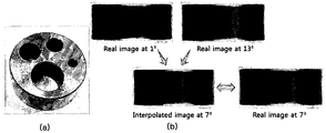
- 5a is a view showing an Al specimen prepared for verification of the application of the image interpolation technique
- 5B is a view showing comparison data between an interpolated image and a real image in a 7 ° rotated direction calculated using two-dimensional X-ray images in a 1 ° rotated direction and a 13 ° rotated direction.
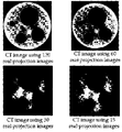
- FIG. 6 is a view showing an image obtained by applying the OSEM technique that is a technique for obtaining a CT image using the interpolated image
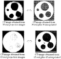
- FIG. 7 is a view showing improved CT image results after applying the image interpolation technique to the 30 and 15 real shot images
- FIG. 8 is a diagram illustrating a result of comparing an improved image and 120 actual captured images after applying an image interpolation technique to three actual captured images;
- FIG. 1A and 1B are diagrams illustrating a non-rotating CT system according to an embodiment of the present invention
- FIG. 2 is a conceptual diagram showing various types of X-ray guides applied to a non-rotating CT system according to an embodiment of the present invention
- 3 is a conceptual diagram showing the shape of a K ⁇ X-ray filter attached to the X-ray guide of FIG. 2
- FIG. 4 is a graph showing the function of the K ⁇ X-ray filter.
- the non-rotating CT system includes an X-ray generator 110, an X-ray detector 120, position correction sensors 112 and 122, a controller 130, a data processor 140, It is composed of an image processor 150.
- a plurality of X-ray generators 110 and X-ray detectors 120 may be used. To illustrate this, in FIG. 1A, the X-ray generators 110 and X-ray detectors 120 are respectively 3.
- FIG. 1B illustrates a state in which each unit is arranged, and FIG. 1B illustrates a state in which five X-ray generators 110 and X-ray detectors 120 are arranged.
- the X-ray generating unit 110 generates X-rays and transmits the light to the object 200, and the X-ray detecting unit 120 detects X-rays passing through the object 200 and is to be inspected 200.
- a plurality can be installed in a radial form around the center.
- Each of the X-ray generator 110 and the X-ray detector 120 may be disposed at the same interval as the test object 200, and the plurality of X-ray generators 110 and the X-ray detector 120 may be placed under test. It may be operated simultaneously for tomography imaging of 200.
- the X-ray generator 110 is radially disposed at regular intervals about the subject 200 in the X-ray CT system, and the position correction sensor 112 is provided at one side, and the X-ray detector 120 is X It is disposed in the spaced space between the line generator 110 is installed alternately with the X-ray generator 110, the position correction sensor 122 is provided on one side.
- the position correction sensors 112 and 122 transmit data about the position and direction of the X-ray generator 110 and the X-ray detector 120 to the controller 130 according to the size of the subject 200 that requires X-ray CT imaging. Function.
- the control unit 130 receives signals from the position correction sensors 112 and 122 provided in the X-ray generating unit 110 and the X-ray detecting unit 120 to face each other and the X-ray generating unit 110 and the X-ray detecting unit ( Adjust the position of 120) to correspond exactly with each other.
- the control unit 130 receives the signals of the position correction sensors 112 and 122 so that the X-rays generated from the one X-ray generating unit 110 may be examined. Function to adjust the position and direction of the X-ray generator 110 and the X-ray detector 120 to be transmitted only to the X-ray detector 120 designated to face each X-ray generator 110 after passing through do. Since the position and the direction can be adjusted, an unnecessary configuration can be eliminated, so that the number of the X-ray generator 110 and the X-ray detector 120 can also be freely adjusted to three or five.
- the data processor 140 stores the 2D X-ray image obtained by the X-ray detector 120 and applies an image interpolation technique to calculate the 2D X-ray image between the two directions, and the image processor 150 stores the data.
- the data of the processing unit 140 is converted into CT image data.
- the X-ray guide 115 is provided on one side of the X-ray generator 110 toward the test subject 200, and the X-ray guide 115 may be made of an X-ray hygroscopic material.
- Figure 2 shows a variety of forms of the X-ray guide, it may be a hollow cylindrical or cuboid structure. That is, the outer shape is not limited as long as the flow path of the X-ray is secured and hollow.
- the X-ray guide 115 structure prevents the dispersion and interference of X-rays and generates parallel X-rays of short wavelength.
- a K ⁇ X-ray filter 118 may be provided at the end of the X-ray guide 115 of the X-ray generator 110 to prevent mutual interference between K ⁇ and K ⁇ characteristic X-rays.
- the X-rays are composed of continuous X-rays and characteristic X-rays, and since the degradation of the X-ray image due to mutual interference between characteristic X-rays may occur, the K ⁇ X-ray filter 118 functions to transmit only K ⁇ X-rays.
- one side of the X-ray detection unit 120 is provided with an X-ray guide 125 toward the test subject 200, and the X-rays generated by the X-ray generator 110 facing the front pass through the test subject 200.
- X-rays are transmitted only to the designated X-ray detector 120, and the X-ray guide 125 may be made of an X-ray hygroscopic material.
- An elastic scattering prevention filter 128 may be provided at the end of the X-ray guide 125 of the X-ray detecting unit 120. Elastic scattering may occur in the X-rays transmitted through the inspected object 200, and thus, the resolution of the image may be deteriorated.
- an elastic scattering prevention filter 128 may be additionally installed in front of the X-ray detector 120 to prevent this. It is desirable to.
- the elastic scattering prevention filter 128 may be composed of a mesh-type film made of a metal material and may be composed of a porous film made of a metal material.
- the shape of the K ⁇ X-ray filter coincides with the hollow shape of the X-ray guide 115 provided in the X-ray generator 110, and the shape thereof changes according to the shape of the X-ray guide. It is not limited to any particular shape.
- the K ⁇ X-ray filter 118 used in the present invention varies depending on the material of the subject (target).
- the K ⁇ X-ray filter 118 is Zr (zirconium), and the target is Cu ( Copper), the K ⁇ X-ray filter 118 is Ni (nickel), and if the target is Co (cobalt), the K ⁇ X-ray filter 118 is Fe (iron), and if the target is Fe (iron), the K ⁇ X-ray filter 118 Is Mn (manganese), and if the target is Cr (chromium), the K ⁇ X-ray filter 118 may use V (vanadium) (see Table 1).
- the transmittance of the K ⁇ X-ray filter 118 used for each target is as shown in [Table 1], and the numerical value of “I (K ⁇ ) permeation / I (K ⁇ ) incidence” shows the transmission intensity of K ⁇ X-rays. 4 indicates that when the target is Cu (copper) and the K ⁇ X-ray filter 118 is Ni (nickel), the K ⁇ X-rays are hardly transmitted by using the K ⁇ X-ray filter 118 than when the filter is not used. It can be seen that the degradation of the resolution of the X-ray image due to mutual interference of K ⁇ X-rays can be prevented.
- a 2D X-ray image for various directions is calculated through image interpolation, and finally, a precise CT image is obtained using the same.
- the data processor 140 and the data processor 140 are configured to store a 2D X-ray image obtained from the X-ray detector 120 and to calculate a 2D X-ray image between two directions by applying an image interpolation technique.
- the image processing unit 150 for converting the data of the CT image data is further provided.
- the data processor 140 not only stores the 2D X-ray image, but also calculates the 2D X-ray image between the X-ray generators 110. At this time, the following image interpolation technique is applied as a method of image calculation.
- FIG. 5A is a view illustrating an Al specimen manufactured for verification of an image interpolation technique
- FIG. 5B is a 7 ° rotation calculated using two-dimensional X-ray images in a 1 ° rotated direction and a 13 ° rotated direction.
- After applying the image interpolation technique using the two-dimensional X-ray image obtained from the general X-ray system it shows the result of calculating the two-dimensional X-ray image in the direction between the two directions. It can be seen that it is in good agreement with the actual image.
- Lucas-Kanade algorithm can be applied for the direct calculation of motion vectors.
- the above equation can be expressed as the following determinant.
- the motion vector may be calculated from the following determinant.
- any point in time of the i-th pixel to be interpolated The positions x p and y p and the intensity I p (x p , y p ) are respectively determined by using two actual X-ray images at the time points t ⁇ and t ⁇ corresponding to the X-ray radiation angles ⁇ and ⁇ , respectively. Can be calculated Where t p is the time corresponding to the angle at which image interpolation is performed Is regarded as '1' as normalized time.
- 'n' is the number of uniform angular intervals to perform image interpolation
- FIG. 6 shows an image obtained by applying the following OSEM technique, which is a technique for acquiring CT images using interpolated images. It is possible.
- silver Intensity at (n + 1) iteration of pixels M and N are the number of rows and columns of pixels in a two-dimensional X-ray image, L is the number of subsets, Is the expected function of the j-th X-ray reaching the i-th detector pixel, Electron emission data.
- a high-resolution CT image when using 120 or 60 two-dimensional X-ray images, a high-resolution CT image can be calculated, but when using 30 and 15 two-dimensional X-ray images, a bad resolution CT image can be calculated. This is a limitation of the general tomography acquisition technique.
- Fig. 7 shows the improved CT image results after using the image interpolation technique.
- Tomography images can be calculated using 30 two-dimensional X-ray interpolation images and 30 actual two-dimensional X-ray images obtained by the image interpolation technique. In this case, it is shown that the low resolution of the tomography image obtained by using 30 or 15 2D X-ray images can be greatly increased.
- the CT image finally obtained as described above is displayed as an image on the outside by a separate display device.
- the present invention adopts an X-ray guide, thereby preventing the degradation of the image sensitivity due to the X-ray interference generated in the plurality of X-ray generators, and prevents the degradation of the sensitivity of the data due to the phase shift of the X-rays and the interference. Can be.
Landscapes
- Health & Medical Sciences (AREA)
- Life Sciences & Earth Sciences (AREA)
- Engineering & Computer Science (AREA)
- Medical Informatics (AREA)
- Radiology & Medical Imaging (AREA)
- Molecular Biology (AREA)
- Biophysics (AREA)
- Nuclear Medicine, Radiotherapy & Molecular Imaging (AREA)
- Optics & Photonics (AREA)
- Pathology (AREA)
- Physics & Mathematics (AREA)
- Biomedical Technology (AREA)
- Heart & Thoracic Surgery (AREA)
- High Energy & Nuclear Physics (AREA)
- Surgery (AREA)
- Animal Behavior & Ethology (AREA)
- General Health & Medical Sciences (AREA)
- Public Health (AREA)
- Veterinary Medicine (AREA)
- Pulmonology (AREA)
- Theoretical Computer Science (AREA)
- Apparatus For Radiation Diagnosis (AREA)
Abstract
개시된 본 발명에 따른 무회전 CT 시스템은 피검사체를 중심으로 일정 간격 이격되어 방사상으로 배치되며 일측에 위치보정센서가 구비된 다수의 X선 발생부, 상기 X선 발생부 사이의 이격된 공간에 배치되어 상기 X선 발생부와 교대로 설치되며 일측에 위치보정센서가 구비된 다수의 X선 검출부, 상기 X선 발생부와 X선 검출부에 구비된 위치보정센서의 신호를 수신하여 서로 대면하는 각각의 X선 발생부와 X선 검출부의 위치가 서로 정대응되도록 조절하는 제어부, 상기 X선 검출부에서 획득한 2차원 X선 영상을 저장하고 영상보간기법을 적용하여 두 방향 사이의 2차원 X선 영상을 계산하도록 하는 데이터처리부 및, 상기 데이터처리부의 데이터를 CT 영상 데이터로 변환하는 영상처리부;를 포함하는 것을 특징으로 한다.
Description
본 발명은 CT 촬영 시 대상 물체 또는 장비의 회전이 필요없는 CT 시스템에 관한 것으로서, 다수의 X선 발생부와 X선 검출부를 포함하고 있는 무회전 CT 시스템에 관한 것이다.
전산화단층촬영(Computerized Tomography, 이하 CT) 장치는 일정량의 선상의 X선속을 신체촬영부위에 투과시키고, X선 검출기가 투과된 X선 강도 변화를 획득하여 신체촬영부위의 각 점의 X선 흡수율을 구해 이것을 영상으로 재구성하는 장치이다.
기존의 X선 CT 장치의 경우 하나 혹은 두 개의 소스와 디텍터를 활용하여 물체를 회전시키거나 소스와 디텍터를 물체 주위로 회전시켜 다양한 각도에 대한 2차원 X선 영상을 획득한 후 CT 영상으로 변환하는 과정을 거친다.
그러나 이와 같은 CT 촬영장치는 한 지점의 단면 영상을 얻기 위해 다양한 각도에 대한 2차원 X선 영상 촬영을 하여야 하고, 이때 촬영에 많은 시간이 소요되며 정적인 상태의 피검사체에 대한 CT 촬영만이 가능한 한계점이 있다.
특히 운동 중인 대상물, 외부하중에 의해 변형중인 대상물들, 즉 짧은 시간에 급속한 변화가 존재하는 대상물들에 대한 실시간 CT 촬영은 불가능하다.
또한 일반적인 X선 CT 장치의 경우, 많은 수의 방향에 대한 2차원 X선 영상을 획득하여야 하므로, 병원에서 환자의 검진을 위하여 사용할 때 환자의 X선 피폭량을 증가시키는 문제점이 존재하며 X선 촬영 시 많은 시간이 소요되어 환자에게 불편을 가중시키게 된다.
본 발명은 상기와 같은 점을 감안하여 안출된 것으로서 다양한 대상물에 대한 X선 영상을 임의의 시점에 대해 매 순간 획득해 낸 후, 획득한 최소 수의 2차원 X선 영상들과 영상보간기법을 이용하여 대상물의 매 시점에 대한 CT 영상을 구축할 수 있는 무회전 CT 시스템을 제공하는 것을 목적으로 한다.
상기와 같은 목적을 달성하기 위해 제공되는 본 발명에 따른 무회전 CT 시스템은 피검사체를 중심으로 일정 간격 이격되어 방사상으로 배치되며 일측에 위치보정센서가 구비된 다수의 X선 발생부; 상기 X선 발생부 사이의 이격된 공간에 배치되어 상기 X선 발생부와 교대로 설치되며 일측에 위치보정센서가 구비된 다수의 X선 검출부; 상기 X선 발생부와 X선 검출부에 구비된 위치보정센서의 신호를 수신하여 서로 대면하는 각각의 X선 발생부와 X선 검출부의 위치가 서로 정대응되도록 조절하는 제어부;를 포함하는 것을 특징으로 한다.
여기서, 상기 X선 발생부의 일측에는 상기 피검사체를 향하여 X선 가이드가 구비되는 것이 좋다.
또한, 상기 X선 검출부의 일측에는 상기 피검사체를 향하여 X선 가이드가 구비되며 정대면되는 X선 발생부로터 발생된 X선이 상기 피검사체를 투과한 후 지정된 X선 검출부로만 X선이 전달되는 것이 바람직하다.
상기 X선 발생부와 X선 검출부의 X선 가이드는 X선 흡습재료로 구성된 것이 좋고, 상기 X선 발생부의 X선 가이드 끝단에 Kα 및 Kβ 특성 X선 간의 상호 간섭을 막도록 기능하는 Kα X선 필터가 구비되는 것이 좋으며, 상기 X선 검출부의 X선 가이드 끝단에 탄성산란방지필터가 구비되는 것이 바람직하다.
여기서, 상기 제어부는 상기 위치보정센서의 신호를 수신하여 하나의 X선 발생부로부터 발생된 X선이 피검사체를 투과한 후 각각의 X선 발생부와 대면되도록 지정된 X선 검출부로만 전달될 수 있게 상기 X선 발생부 및 X선 검출부의 위치 및 방향을 조절하는 것이 바람직하다.
상기와 같은 목적을 달성하기 위해 제공되는 본 발명의 실시 예에 따른 무회전 CT 시스템은 피검사체를 중심으로 일정 간격 이격되어 방사상으로 배치되며 일측에 위치보정센서가 구비된 다수의 X선 발생부; 상기 X선 발생부 사이의 이격된 공간에 배치되어 상기 X선 발생부와 교대로 설치되며 일측에 위치보정센서가 구비된 다수의 X선 검출부; 상기 X선 발생부와 X선 검출부에 구비된 위치보정센서의 신호를 수신하여 서로 대면하는 각각의 X선 발생부와 X선 검출부의 위치가 서로 정대응되도록 조절하는 제어부; 상기 X선 검출부에서 획득한 2차원 X선 영상을 저장하고 영상보간기법을 적용하여 두 방향 사이의 2차원 X선 영상을 계산하도록 하는 데이터처리부; 및, 상기 데이터처리부의 데이터를 CT 영상 데이터로 변환하는 영상처리부;를 포함하는 것을 특징으로 한다.
여기서, 상기 X선 발생부의 일측에는 상기 피검사체를 향하여 X선 가이드가 구비되는 것이 좋다.
또한, 상기 X선 검출부의 일측에는 상기 피검사체를 향하여 X선 가이드가 구비되며 정대면되는 X선 발생부로터 발생된 X선이 상기 피검사체를 투과한 후 지정된 X선 검출부로만 X선이 전달되는 것이 바람직하다.
상기 X선 발생부와 X선 검출부의 X선 가이드는 X선 흡습재료로 구성된 것이 좋고, 상기 X선 발생부의 X선 가이드 끝단에 Kα 및 Kβ 특성 X선 간의 상호 간섭을 막도록 기능하는 Kα X선 필터가 구비되는 것이 좋으며, 상기 X선 검출부의 X선 가이드 끝단에 탄성산란방지필터가 구비되는 것이 바람직하다.
여기서, 상기 제어부는 상기 위치보정센서의 신호를 수신하여 하나의 X선 발생부로부터 발생된 X선이 피검사체를 투과한 후 각각의 X선 발생부와 대면되도록 지정된 X선 검출부로만 전달될 수 있게 상기 X선 발생부 및 X선 검출부의 위치 및 방향을 조절하는 것이 바람직하다.
또한, 상기 영상보간기법에 의하여 획득한 데이터는 OSEM 기법으로 영상을 CT 영상 데이터로 변환하는 것이 좋다.
본 발명에 따른 무회전 CT 시스템에 의하면 시시각각 변화하는 상황에 대한 대상물의 내부구조의 검사가 가능하여 산업용 재료를 대상으로 할 경우, 변형이 발생 중인 재료에 대한 실시간의 내부 구조 분석 및 이동 중인 대상물에 대한 단면 구조 분석이 가능하며, 의료용으로서 환자를 대상으로 할 경우, 환자에 대한 방사선 피폭량을 획기적으로 줄일 수 있고, 실시간 혈관의 단면 변형 상태, 심장 박동 시의 내부 구조 등의 변화, 움직임이 존재하는 관절의 형상 등의 분석 등이 가능하여 환자에 대한 보다 실질적인 영상진단자료의 확보가 가능한 효과가 있다.
도 1a 및 도 1b는 본 발명의 일 실시 예에 따른 무회전 CT 시스템을 나타낸 구성도,
도 2는 본 발명의 일 실시 예에 따른 무회전 CT 시스템에 적용되는 다양한 형태의 X선 가이드를 나타낸 개념도,
도 3은 도 2의 X선 가이드에 장착되는 Kα X선 필터의 형태를 나타내는 개념도,
도 4는 Kα X선 필터의 기능을 나타내는 그래프,
도 5a는 영상보간기법 적용의 검증을 위해 제작된 Al 시편을 나타낸 도면,
도 5b는 1°회전된 방향 및 13°회전된 방향의 2차원 X선 영상들을 이용하여 계산된 7°회전된 방향의 보간영상과 실제영상 간의 비교 데이터를 나타낸 도면,
도 6은 보간된 영상을 이용하여 CT 영상을 획득하기 위한 기법인 OSEM 기법을 적용하여 획득한 영상을 나타낸 도면,
도 7은 30장과 15장의 실제 촬영 영상에 대하여 영상보간기법을 적용한 후 개선된 CT 영상 결과를 나타낸 도면,
도 8은 3장의 실제 촬영 영상에 대하여 영상보간기법을 적용한 후 개선된 영상과 120장의 실제 촬영 영상을 서로 비교한 결과를 나타낸 도면 및,
도 9는 인체와 같이 복잡한 구조를 포함하고 있는 생체재료에 대한 적용가능성을 판단하기 위하여 돼지의 발을 시편으로 사용한 후, 각각 5장, 3장의 실제 촬영 영상을 이용하여 영상보간기법을 적용한 후 개선된 CT 영상을 획득하였고 이를 120장의 실제 촬영영상을 이용하여 OSEM기법을 이용하여 획득한 영상과 비교한 결과를 나타낸 도면이다.
본 발명의 상기와 같은 목적, 특징 및 다른 장점들은 첨부도면을 참조하여 본 발명의 바람직한 실시 예를 상세히 설명함으로써 더욱 명백해질 것이다. 이하, 첨부된 도면을 참조하여 본 발명의 실시 예에 따른 무회전 CT 시스템을 상세히 설명하기로 한다.
도 1a 및 도 1b는 본 발명의 일 실시 예에 따른 무회전 CT 시스템을 나타낸 구성도이고 도 2는 본 발명의 일 실시 예에 따른 무회전 CT 시스템에 적용되는 다양한 형태의 X선 가이드를 나타낸 개념도이며 도 3은 도 2의 X선 가이드에 장착되는 Kα X선 필터의 형태를 나타내는 개념도이고 도 4는 Kα X선 필터의 기능을 나타내는 그래프이다.
도 1a 및 도 1b를 살펴보면, 본 발명에 따른 무회전 CT 시스템은 X선 발생부(110), X선 검출부(120), 위치보정센서(112,122), 제어부(130), 데이터처리부(140), 영상처리부(150)로 구성된다. 본 발명에서의 X선 발생부(110)와 X선 검출부(120)는 다수개 사용하는 것이 가능하며 이를 설명하기 위하여 도 1a에서는 X선 발생부(110)와 X선 검출부(120)가 각각 3개씩 배치된 상태를 도시하고 있고, 도 1b에서는 X선 발생부(110)와 X선 검출부(120)가 각각 5개씩 배치된 상태를 도시하고 있다.
X선 발생부(110)는 X선을 발생시켜 피검사체(200)에 투과하기 위한 것이고, X선 검출부(120)는 피검사체(200)를 투과한 X선을 감지하기 위한 것으로서 피검사체(200)를 중심으로 방사형태로 다수개가 설치될 수 있다. 각각의 X선 발생부(110)와 X선 검출부(120)는 피검사체(200)와 동일한 간격을 두고 배치될 수 있으며 다수개의 X선 발생부(110)와 X선 검출부(120)는 피검사체(200)의 단층 촬영을 위해 동시에 동작할 수 있다.
X선 발생부(110)는 본 X선 CT 시스템에서 피검사체(200)를 중심으로 일정 간격 이격되어 방사상으로 배치되며 일측에 위치보정센서(112)가 구비되고, X선 검출부(120)는 X선 발생부(110) 사이의 이격된 공간에 배치되어 X선 발생부(110)와 교대로 설치되며 일측에 위치보정센서(122)가 구비된다. 위치보정센서(112,122)는 X선 CT 촬영이 필요한 피검사체(200)의 크기에 따라 X선 발생부(110) 및 X선 검출부(120)의 위치 및 방향에 대한 데이터를 제어부(130)로 송신하는 기능을 한다.
제어부(130)는 X선 발생부(110)와 X선 검출부(120)에 구비된 위치보정센서(112,122)의 신호를 수신하여 서로 대면하는 각각의 X선 발생부(110)와 X선 검출부(120)의 위치가 서로 정대응되도록 조절한다.
구체적으로 살펴보면, 본 발명에 따른 무회전 CT 시스템에서 제어부(130)는 위치보정센서(112,122)의 신호를 수신하여 하나의 X선 발생부(110)로부터 발생된 X선이 피검사체(200)를 투과한 후 각각의 X선 발생부(110)와 대면되도록 지정된 X선 검출부(120)로만 전달될 수 있게 상기 X선 발생부(110) 및 X선 검출부(120)의 위치 및 방향을 조절하도록 기능한다. 위치 및 방향을 조절할 수 있기 때문에, 불필요한 구성을 배제할 수 있으므로 X선 발생부(110)와 X선 검출부(120)의 개수도 3개 또는5개 등으로 자유롭게 조절할 수 있다.
데이터처리부(140)는 X선 검출부(120)에서 획득한 2차원 X선 영상을 저장하고 영상보간기법을 적용하여 두 방향 사이의 2차원 X선 영상을 계산하도록 하고, 영상처리부(150)는 데이터처리부(140)의 데이터를 CT 영상 데이터로 변환하도록 기능한다.
여기서, X선 발생부(110)의 일측에는 피검사체(200)를 향하여 X선 가이드(115)가 구비되고, X선 가이드(115)는 X선 흡습재료로 구성되는 것이 좋다. 도 2는 다양한 형태의 X선 가이드를 나타낸 것으로서, 중공형의 원통형 또는 직육면체형의 구조일 수 있다. 즉, X선의 유동경로를 확보한 상태로써 중공형상이라면 외부 형상은 제한받지 않는다. X선 가이드(115) 구조로써 X선의 분산 및 간섭을 방지하고 단파장의 평행 X선을 발생시킬 수 있다.
특히, 다수의 X선 발생부(110)를 사용할 경우, 각각의 소스에서 방사형으로 발생되는 X선으로 인한 상호 간섭효과로 인하여 정밀한 X선 CT 영상을 얻는 것에는 한계가 존재한다. 그러므로 X선 흡습재료를 이용한 X선 가이드(115) 구조를 적용하여 하나의 X선 발생부(110)로부터 발생된 X선이 피검사체(200)를 투과한 후 지정된 X선 검출부(120)로만 전달될 수 있도록 한다.
X선 발생부(110)의 X선 가이드(115) 끝단에 Kα 및 Kβ 특성 X선 간의 상호 간섭을 막도록 기능하는 Kα X선 필터(118)가 구비될 수 있다. X선은 연속 X선 및 특성 X선들로 구성되어 있으며 특성 X선 간의 상호 간섭으로 인한 X선 영상의 해상도 저하가 발생될 수 있으므로 Kα X선 필터(118)는 Kα X선만을 투과하도록 기능한다.
또한, X선 검출부(120)의 일측에는 피검사체(200)를 향하여 X선 가이드(125)가 구비되며 정대면되는 X선 발생부(110)로터 발생된 X선이 피검사체(200)를 투과한 후 지정된 X선 검출부(120)로만 X선이 전달되도록 하고, X선 가이드(125)는 X선 흡습재료로 구성되는 것이 좋다. X선 검출부(120)의 X선 가이드(125) 끝단에 탄성산란방지필터(128)가 구비될 수 있다. 피검사체(200)를 투과한 X선에는 탄성산란이 발생할 수 있으며 이로 인한 영상의 해상도 저하가 발생할 수 있으므로 이를 방지하기 위해 X선 검출부(120) 앞쪽에는 탄성산란방지필터(128)를 추가로 설치하는 것이 바람직하다. 탄성산란방지필터(128)는 금속 재질로 이루어진 메쉬(mesh) 형태의 막으로 구성될 수 있고 금속 재질로 이루어진 다공성 막으로 구성될 수 있다.
도 3 및 도 4를 살펴보면, Kα X선 필터의 형태는 X선 발생부(110)에 구비된 X선 가이드(115)의 중공형상과 일치하는 것으로서 그 형상은 X선 가이드의 형상에 따라 변화하고 특정 형상에 제한되지 않는다. 또한, 본 발명에서 사용되는 Kα X선 필터(118)는 피검사체(타킷)의 재료에 따라 달라지는데, 타깃이 Mo(몰리브덴)이면 Kα X선 필터(118)는 Zr(지르코늄), 타깃이 Cu(구리)이면 Kα X선 필터(118)는 Ni(니켈), 타킷이 Co(코발트)이면 Kα X선 필터(118)는 Fe(철), 타깃이 Fe(철)이면 Kα X선 필터(118)는 Mn(망간), 타깃이 Cr(크롬)이면 Kα X선 필터(118)는 V(바나듐)이 사용될 수 있다(표 1 참조).
[표 1]

각 타깃에 사용되는 Kα X선 필터(118)의 투과도는 [표 1]에 나타난 바와 같고, "I(Kα)투과/I(Kβ)입사" 의 수치는 Kα X선의 투과강도를 나타낸 것이다.도 4는 타깃이 Cu(구리)이고 Kα X선 필터(118)가 Ni(니켈)인 경우, 필터를 사용하지 않았을 때보다 Kα X선 필터(118)를 사용할 경우 Kβ X선이 거의 투과되지 않음을 나타내고 이로써 Kβ X선의 상호 간섭을 인한 X선 영상의 해상도 저하를 방지할 수 있음을 알 수 있다.
상기와 같은 무회전 CT 시스템을 이용하여 최소 방향 수의 2차원 X선 영상을 획득한 후 영상 보간을 통하여 다양한 방향에 대한 2차원 X선 영상을 계산해 낸 후 이를 이용하여 최종적으로 정밀한 CT 영상을 획득할 수 있는 새로운 영상보간기법을 제안한다. 이를 통하여 다양한 피검사체(200)에 대한 X선 영상을 임의의 시점에 대해 매 순간 획득해 낸 후, 획득한 최소 수의 2차원 X선 영상들과 영상보간기법을 이용하여 피검사체(200)의 매 시점에 대한 CT 영상을 구축할 수 있게 된다.
이를 위하여 X선 검출부(120)부터 획득한 2차원 X선 영상을 저장하고 영상보간기법을 적용하여 두 방향 사이의 2차원 X선 영상을 계산하도록 하는 데이터처리부(140) 및, 데이터처리부(140)의 데이터를 CT 영상 데이터로 변환하는 영상처리부(150)가 추가로 구비된다. 데이터처리부(140)는 2차원 X선 영상을 저장할 뿐만 아니라, X선 발생부(110) 간의 2차원 X선 영상을 계산한다. 이때 영상 계산의 방법으로서 아래와 같은 영상보간기법이 적용된다.
도 5는 도 5a는 영상보간기법 적용의 검증을 위해 제작된 Al 시편을 나타낸 도면이고 도 5b는 1°회전된 방향 및 13°회전된 방향의 2차원 X선 영상들을 이용하여 계산된 7°회전된 방향의 보간영상과 실제영상 간의 비교 데이터를 나타낸 도면이다. 즉, 일반적인 X선 시스템으로부터 획득한 2차원 X선 영상을 이용하여 영상보간기법을 적용한 후 두 방향의 사이 방향의 2차원 X선 영상을 계산해 낸 결과를 나타낸 그림으로서 영상보간을 통하여 획득한 영상이 실제영상과 잘 일치하고 있음을 알 수 있다.
이와 같은 영상보간기법을 적용하기 위해서는 먼저 획득한 최소 방향 수의 2차원 X선 영상 간의 회전에 의한 다음과 같은 모션벡터(motion vecter)의 계산이 필요하다.

여기서 x와 y는 임의 시간 t에서의 픽셀의 좌표를 의미하며  와
와  가 x, y 방향의 모션벡터이다. 이러한 모션벡터는 대상물의 임의의 점에 대한 2차원 X선 영상의 강도
  가 시간에 따라 또는 회전방향에 따라 그 값이 변화하지 않는다는 가정으로부터 계산할 수 있다.

여기서 x, y는 각각 영상에 대한 픽셀의 좌표, t는 영상을 획득한 시간, I는 획득한 시간에서 x, y 지점의 강도이며 위 식의 미분에 대하여 테일러 급수를 적용하면 임의 시간 t+dt 에서의 강도 I는 다음과 같은 방정식을 얻을 수 있다.

위 식을 영상강도 보존 가정에 의한 식에 적용할 경우, 다음과 같은 식을 얻을 수 있다.

위 식의 첫 번째 항은 영상보존 가정에 의해 "0"이 되므로 위식은 다음과 같은 식으로 나타낼 수 있다.

위 식은 다음과 같이 간단한 식으로 나타낼 수 있으며

여기서  는 각각 x, y, t 에 대한 영상강도의 미분값이다. 모션벡터의 직접적인 계산을 위하여 Lucas-Kanade 알고리즘을 적용할 수 있으며, 하나의 영상에 대한 각각의 픽셀을 고려할 경우, 위 식은 다음과 같은 행렬식으로 나타낼 수 있다.

여기서  는 각각의 픽셀에 해당하며, 모션벡터는 다음과 같은 행렬식으로부터 계산될 수 있다.

모션벡터가 계산될 경우 다음과 같이 보간될 i 번째 픽셀의 임의의 시점,  의 위치 xp 및 yp 그리고 강도 Ip(xp, yp)는 X선 방사 각도 α 및 β에 해당하는 시점 tα와 tβ에서의 두 개의 실제 X선 영상을 이용하여 다음과 같이 각각 계산할 수 있다. 여기서 tp는 영상 보간이 실시된 각도에 해당하는 시간이며
  는 정규화된 시간으로서 '1'로서 간주한다.


여기서 'n'은 영상 보간을 실시할 균일한 각도 간격의 수이며, 'm'은 영상보간의 횟수를 나타내는 상수임. 만일 α= 0°와 β = 90°를 고려할 경우, n = 3 일 경우, 두 각도 사이의 30°간격으로 보간된 영상을 얻을 수 있으며, n = 5 일 경우 18°간격으로 보간된 영상을 각각 획득할 수 있다. 또한 m = 1 인 경우 30°에서의 보간된 영상을 획득할 수 있고, m = 2 인 경우 60°에서의 보간된 영상을 획득할 수 있다.
영상 보간 기법의 타당성을 검증하기 위하여 제작된 Al 시편을 이용하여 기준 방향으로부터 1°회전된 방향과 13°회전된 방향에 대한 2차원 X선 영상을 획득한 후, 두 영상을 이용하여 7°회전된 방향에 대한 보간 영상을 계산하고, 실제 7°회전된 방향에서 획득한 X선 영상과 비교하여 도 5에 나타내었다.
도 5로부터 보간을 통해 계산된 영상과 실제의 영상이 서로 잘 일치하는 것을 확인할 수 있다.
도 6은 보간된 영상을 이용하여 CT 영상을 획득하기 위한 기법인 다음과 같은 OSEM 기법을 적용하여 획득한 영상을 나타낸 것으로서, 2차원 X선 영상 개수의 감소에 따르는 CT 영상 질의 저하에 대한 확인이 가능하다.

여기서,  은
은  픽셀의 (n+1)iteration 시의 강도, M과 N은 2차원 X선 영상의 픽셀의 행과 열의 개수들, L은 subset의 수,
  는 i번째 디텍터 픽셀에 도달하는 j번째 X선의 기대함수,
  전자 방출데이터이다.
도 6에서 살펴보면, 120장, 60장의 2차원 X선 영상을 이용할 경우, 고해상도의 CT 영상을 계산해 낼 수 있으나 30장 및 15장의 2차원 X선 영상을 이용할 경우 나쁜 해상도의 CT 영상을 계산해 내는 것을 확인할 수 있으며 이것은 일반적인 단층영상 획득 기법의 한계이다.
도 7은 영상보간기법을 사용한 후 개선된 CT 영상 결과를 나타낸 것으로서, 본 연구의 영상보간 기법으로 얻은 30장의 2차원 X선 보간 영상과 30장의 실제 2차원 X선 영상을 이용하여 단층 영상을 계산할 경우, 실제 30장 또는 15장의 2차원 X선 영상을 이용하여 획득한 단층영상의 낮은 해상도를 크게 증가시킬 수 있음을 나타낸 것이다.
이와 같은 영상보간기법을 이용할 경우, 단 3장의 실제 X선 영상으로도 높은 해상도의 단층 영상의 획득이 가능하며, 그 결과를 도 8에 나타내었다.
인체와 같은 복잡한 생체재료에 대한 본 기법의 적용 및 검증을 위하여 돼지 발의 끝부분을 이용한 실험을 실시하였다. 도 9로부터 복잡한 구조의 생체재료 역시 3장 또는 5장의 실제 X선 영상을 이용하여 영상보간기법을 적용할 경우, 120장의 X선 영상으로 OSEM 기법을 적용한 후 획득한 단층영상과 유사한 정밀도의 단층 영상을 획득할 수 있음을 확인할 수 있다.
상기와 같이 최종적으로 획득된 CT 영상은 별도의 디스플레이장치에 의하여 외부에 화상으로 표시된다.
본 발명에 따른 무회전 CT 시스템을 이용할 경우, 환자의 방사선 피폭량을 획기적으로 줄일 수 있고, 움직임이 있는 환자의 부위들, 즉, 척추, 관절, 심장 등과 같은 부위에 대한 임의의 시점에서의 단층영상의 확보가 가능하며 이를 통하여 환자에 대한 보다 실질적인 영상진단자료의 확보가 가능하다. 또한 변형 또는 이동이 존재하는 다양한 물체에 대한 각각의 시점의 상태에 대한 내부 구조의 변화를 검사할 수 있는 효과가 있다.
또한 본 발명에서는 X선 가이드를 채택하고 있어서, 다수 개의 X선 발생부에서 발생하는 X선의 간섭으로 인한 영상 감도 저하를 방지할 수 있고, X선의 위상 편이 및 간섭으로 인한 데이터의 감도의 저하를 막을 수 있다.
이상에서 본 발명의 바람직한 실시 예에 대하여 설명하였으나, 본 발명은 상술한 특정의 실시 예에 한정되지 아니한다. 즉, 본 발명이 속하는 기술분야에서 통상의 지식을 가지는 자라면 첨부된 특허청구범위의 사상 및 범주를 일탈함이 없이 본 발명에 대한 다수의 변경 및 수정이 가능하며, 그러한 모든 적절한 변경 및 수정의 균등물들도 본 발명의 범위에 속하는 것으로 간주되어야 할 것이다.
Claims (15)
- 피검사체를 중심으로 일정 간격 이격되어 방사상으로 배치되며 일측에 위치보정센서가 구비된 다수의 X선 발생부;상기 X선 발생부 사이의 이격된 공간에 배치되어 상기 X선 발생부와 교대로 설치되며 일측에 위치보정센서가 구비된 다수의 X선 검출부;상기 X선 발생부와 X선 검출부에 구비된 위치보정센서의 신호를 수신하여 서로 대면하는 각각의 X선 발생부와 X선 검출부의 위치가 서로 정대응되도록 조절하는 제어부;를 포함하는 것을 특징으로 하는 무회전 CT 시스템.
- 제 1 항에 있어서,상기 X선 발생부의 일측에는 상기 피검사체를 향하여 X선 가이드가 구비되는 것을 특징으로 하는 무회전 CT 시스템.
- 제 1 항에 있어서,상기 X선 검출부의 일측에는 상기 피검사체를 향하여 X선 가이드가 구비되며 정대면되는 X선 발생부로터 발생된 X선이 상기 피검사체를 투과한 후 지정된 X선 검출부로만 X선이 전달되는 것을 특징으로 하는 무회전 CT 시스템.
- 제 2 항 또는 제 3 항에 있어서,상기 X선 발생부와 X선 검출부의 X선 가이드는 X선 흡습재료로 구성된 것을 특징으로 하는 무회전 CT 시스템.
- 제 2 항에 있어서,상기 X선 발생부의 X선 가이드 끝단에 Kα 및 Kβ 특성 X선 간의 상호 간섭을 막도록 기능하는 Kα X선 필터가 구비되는 것을 특징으로 하는 무회전 CT 시스템.
- 제 3 항에 있어서,상기 X선 검출부의 X선 가이드 끝단에 탄성산란방지필터가 구비되는 것을 특징으로 하는 무회전 CT 시스템.
- 제 1 항에 있어서,상기 제어부는 상기 위치보정센서의 신호를 수신하여 하나의 X선 발생부로부터 발생된 X선이 피검사체를 투과한 후 각각의 X선 발생부와 대면되도록 지정된 X선 검출부로만 전달될 수 있게 상기 X선 발생부 및 X선 검출부의 위치 및 방향을 조절하는 것을 특징으로 하는 무회전 CT 시스템.
- 피검사체를 중심으로 일정 간격 이격되어 방사상으로 배치되며 일측에 위치보정센서가 구비된 다수의 X선 발생부;상기 X선 발생부 사이의 이격된 공간에 배치되어 상기 X선 발생부와 교대로 설치되며 일측에 위치보정센서가 구비된 다수의 X선 검출부;상기 X선 발생부와 X선 검출부에 구비된 위치보정센서의 신호를 수신하여 서로 대면하는 각각의 X선 발생부와 X선 검출부의 위치가 서로 정대응되도록 조절하는 제어부;상기 X선 검출부에서 획득한 2차원 X선 영상을 저장하고 영상보간기법을 적용하여 두 방향 사이의 2차원 X선 영상을 계산하도록 하는 데이터처리부; 및,상기 데이터처리부의 데이터를 CT 영상 데이터로 변환하는 영상처리부;를 포함하는 것을 특징으로 하는 무회전 CT 시스템.
- 제 8 항에 있어서,상기 X선 발생부의 일측에는 상기 피검사체를 향하여 X선 가이드가 구비되는 것을 특징으로 하는 무회전 CT 시스템.
- 제 8 항에 있어서,상기 X선 검출부의 일측에는 상기 피검사체를 향하여 X선 가이드가 구비되며 정대면되는 X선 발생부로터 발생된 X선이 상기 피검사체를 투과한 후 지정된 X선 검출부로만 X선이 전달되는 것을 특징으로 하는 무회전 CT 시스템.
- 제 9 항 또는 제 10 항에 있어서,상기 X선 발생부와 X선 검출부의 X선 가이드는 X선 흡습재료로 구성된 것을 특징으로 하는 무회전 CT 시스템.
- 제 9 항에 있어서,상기 X선 발생부의 X선 가이드 끝단에 Kα 및 Kβ 특성 X선 간의 상호 간섭을 막도록 기능하는 Kα X선 필터가 구비되는 것을 특징으로 하는 무회전 CT 시스템.
- 제 10 항에 있어서,상기 X선 검출부의 X선 가이드 끝단에 탄성산란방지필터가 구비되는 것을 특징으로 하는 무회전 CT 시스템.
- 제 8 항에 있어서,상기 제어부는 상기 위치보정센서의 신호를 수신하여 하나의 X선 발생부로부터 발생된 X선이 피검사체를 투과한 후 각각의 X선 발생부와 대면되도록 지정된 X선 검출부로만 전달될 수 있게 상기 X선 발생부 및 X선 검출부의 위치 및 방향을 조절하는 것을 특징으로 하는 무회전 CT 시스템.
- 제 8 항에 있어서,상기 영상보간기법에 의하여 획득한 2차원 X선 데이터는 OSEM 기법으로 영상을 CT 영상 데이터로 변환하는 것을 특징으로 하는 무회전 CT 시스템.
Priority Applications (1)
| Application Number | Priority Date | Filing Date | Title |
|---|---|---|---|
| US14/000,259 US9179878B2 (en) | 2011-12-09 | 2012-01-05 | Non-rotational computerized tomography system |
Applications Claiming Priority (2)
| Application Number | Priority Date | Filing Date | Title |
|---|---|---|---|
| KR1020110131452A KR101146833B1 (ko) | 2011-12-09 | 2011-12-09 | 무회전 ct 시스템 |
| KR10-2011-0131452 | 2011-12-09 |
Publications (1)
| Publication Number | Publication Date |
|---|---|
| WO2013085098A1 true WO2013085098A1 (ko) | 2013-06-13 |
Family
ID=46272238
Family Applications (1)
| Application Number | Title | Priority Date | Filing Date |
|---|---|---|---|
| PCT/KR2012/000123 Ceased WO2013085098A1 (ko) | 2011-12-09 | 2012-01-05 | 무회전 ct 시스템 |
Country Status (3)
| Country | Link |
|---|---|
| US (1) | US9179878B2 (ko) |
| KR (1) | KR101146833B1 (ko) |
| WO (1) | WO2013085098A1 (ko) |
Families Citing this family (12)
| Publication number | Priority date | Publication date | Assignee | Title |
|---|---|---|---|---|
| KR101382735B1 (ko) | 2012-10-12 | 2014-04-08 | 전남대학교산학협력단 | 산업용 고해상도 모바일 x-선 ct 시스템 및 이를 이용한 3차원 영상 획득 방법 |
| KR102045424B1 (ko) | 2012-11-12 | 2019-12-03 | 삼성디스플레이 주식회사 | 엑스선 발생장치, 엑스선 검출장치 및 이를 이용한 엑스선 영상 촬영 시스템 |
| US9986983B2 (en) | 2014-10-31 | 2018-06-05 | Covidien Lp | Computed tomography enhanced fluoroscopic system, device, and method of utilizing the same |
| US10716525B2 (en) | 2015-08-06 | 2020-07-21 | Covidien Lp | System and method for navigating to target and performing procedure on target utilizing fluoroscopic-based local three dimensional volume reconstruction |
| US10674982B2 (en) | 2015-08-06 | 2020-06-09 | Covidien Lp | System and method for local three dimensional volume reconstruction using a standard fluoroscope |
| US10702226B2 (en) | 2015-08-06 | 2020-07-07 | Covidien Lp | System and method for local three dimensional volume reconstruction using a standard fluoroscope |
| KR101732961B1 (ko) | 2015-08-13 | 2017-05-10 | 한국과학기술원 | 다중 감마소스 ct 영상 재건 방법 및 장치 |
| US11172895B2 (en) | 2015-12-07 | 2021-11-16 | Covidien Lp | Visualization, navigation, and planning with electromagnetic navigation bronchoscopy and cone beam computed tomography integrated |
| US11051886B2 (en) | 2016-09-27 | 2021-07-06 | Covidien Lp | Systems and methods for performing a surgical navigation procedure |
| US10699448B2 (en) | 2017-06-29 | 2020-06-30 | Covidien Lp | System and method for identifying, marking and navigating to a target using real time two dimensional fluoroscopic data |
| EP3694412B1 (en) | 2017-10-10 | 2025-12-31 | Covidien LP | SYSTEM AND METHOD FOR IDENTIFYING AND MARKING A TARGET IN A THREE-DIMENSIONAL FLUOROSCOPIC RECONSTRUCTION |
| US10905498B2 (en) | 2018-02-08 | 2021-02-02 | Covidien Lp | System and method for catheter detection in fluoroscopic images and updating displayed position of catheter |
Citations (4)
| Publication number | Priority date | Publication date | Assignee | Title |
|---|---|---|---|---|
| JP2005510278A (ja) * | 2001-11-23 | 2005-04-21 | ジーイー・メディカル・システムズ・グローバル・テクノロジー・カンパニー・エルエルシー | X線源・画像間の可変距離を利用した3d再構成システム及び方法 |
| US20050175143A1 (en) * | 2002-06-03 | 2005-08-11 | Osamu Miyazaki | Multi-slice x-ray ct device |
| JP2007502652A (ja) * | 2003-08-20 | 2007-02-15 | バリアン・メディカル・システムズ・テクノロジーズ・インコーポレイテッド | 自動画像解像度強化を有するx線画像装置 |
| JP2010234003A (ja) * | 2009-03-31 | 2010-10-21 | Fujifilm Corp | 乳房撮影定位装置 |
Family Cites Families (6)
| Publication number | Priority date | Publication date | Assignee | Title |
|---|---|---|---|---|
| US5166966A (en) * | 1990-02-07 | 1992-11-24 | The United States Of America As Represented By The United States Department Of Energy | Coated x-ray filters |
| DE9012435U1 (de) * | 1990-08-30 | 1992-01-02 | Siemens AG, 8000 München | Medizinische Einrichtung mit einer Lagervorrichtung für einen Strahlensender oder einen Strahlenempfänger |
| US6801594B1 (en) * | 1997-11-26 | 2004-10-05 | General Electric Company | Computed tomography fluoroscopy system |
| US7192031B2 (en) * | 2004-02-05 | 2007-03-20 | General Electric Company | Emitter array configurations for a stationary CT system |
| US7366279B2 (en) * | 2004-07-29 | 2008-04-29 | General Electric Company | Scatter control system and method for computed tomography |
| US7496181B2 (en) * | 2005-11-28 | 2009-02-24 | The Board Of Trustees Of The Leland Stanford Junior University | X-ray collimator for imaging with multiple sources and detectors |
-
2011
- 2011-12-09 KR KR1020110131452A patent/KR101146833B1/ko not_active Expired - Fee Related
-
2012
- 2012-01-05 US US14/000,259 patent/US9179878B2/en not_active Expired - Fee Related
- 2012-01-05 WO PCT/KR2012/000123 patent/WO2013085098A1/ko not_active Ceased
Patent Citations (4)
| Publication number | Priority date | Publication date | Assignee | Title |
|---|---|---|---|---|
| JP2005510278A (ja) * | 2001-11-23 | 2005-04-21 | ジーイー・メディカル・システムズ・グローバル・テクノロジー・カンパニー・エルエルシー | X線源・画像間の可変距離を利用した3d再構成システム及び方法 |
| US20050175143A1 (en) * | 2002-06-03 | 2005-08-11 | Osamu Miyazaki | Multi-slice x-ray ct device |
| JP2007502652A (ja) * | 2003-08-20 | 2007-02-15 | バリアン・メディカル・システムズ・テクノロジーズ・インコーポレイテッド | 自動画像解像度強化を有するx線画像装置 |
| JP2010234003A (ja) * | 2009-03-31 | 2010-10-21 | Fujifilm Corp | 乳房撮影定位装置 |
Also Published As
| Publication number | Publication date |
|---|---|
| KR101146833B1 (ko) | 2012-05-21 |
| US9179878B2 (en) | 2015-11-10 |
| US20130329852A1 (en) | 2013-12-12 |
Similar Documents
| Publication | Publication Date | Title |
|---|---|---|
| WO2013085098A1 (ko) | 무회전 ct 시스템 | |
| JPS61220628A (ja) | X線動態像計測装置 | |
| US20080094396A1 (en) | System For The Three-Dimensional Imaging Of A Moving Joint | |
| WO2023229415A1 (ko) | Ar 영상 제공 방법 및 ar 영상 제공 장치 | |
| US20060074287A1 (en) | Systems, methods and apparatus for dual mammography image detection | |
| CN102397081A (zh) | 用于二维/三维配准的方法 | |
| WO2020055039A1 (ko) | 파킨슨 병 진단 장치 및 방법 | |
| WO2020256276A2 (ko) | 초음파 스캐너의 탐촉자의 위치 및 자세 추적을 이용한 초음파 영상 제공 장치 및 방법 | |
| WO2013162218A1 (ko) | 방사선투시시스템 | |
| US11051781B2 (en) | Medical diagnostic imaging apparatus | |
| WO2020209568A1 (ko) | 방사선 진단 및 치료 장치의 모션 평가 시스템 및 방법 | |
| JP4584550B2 (ja) | X線計測装置 | |
| JP4485474B2 (ja) | X線計測装置 | |
| JPH06133961A (ja) | コンピュータ断層撮影装置 | |
| JP6510198B2 (ja) | 医用画像処理装置及び医用画像処理方法 | |
| RU93032495A (ru) | Вычислительный томограф | |
| JP2001095793A (ja) | X線ct装置 | |
| WO2016111432A1 (ko) | 영상 촬영 방법 및 장치 | |
| WO2009091202A2 (ko) | 트렁케이션 아티팩트를 보정하는 방법 | |
| WO2014168288A1 (ko) | 엑스선 영상장치 및 엑스선 영상장치의 이미징 방법 | |
| JP2005304905A (ja) | 放射線撮影装置 | |
| WO2023219370A1 (ko) | 대상체 또는 수술 도구의 위치를 결정하는 방법 및 시스템 | |
| JP2009005827A (ja) | 放射線撮像装置 | |
| JP4512833B2 (ja) | 物体内部位計測システム、物体内部位計測用演算装置、物体内部位計測用プログラム及びそのプログラムを記録したコンピュータ読み取り可能な記録媒体 | |
| US8867699B2 (en) | Radiographic device |
Legal Events
| Date | Code | Title | Description |
|---|---|---|---|
| 121 | Ep: the epo has been informed by wipo that ep was designated in this application |
Ref document number: 12854999 Country of ref document: EP Kind code of ref document: A1 |
|
| WWE | Wipo information: entry into national phase |
Ref document number: 14000259 Country of ref document: US |
|
| NENP | Non-entry into the national phase |
Ref country code: DE |
|
| 122 | Ep: pct application non-entry in european phase |
Ref document number: 12854999 Country of ref document: EP Kind code of ref document: A1 |