WO2013084941A1 - Battery module - Google Patents
Battery module Download PDFInfo
- Publication number
- WO2013084941A1 WO2013084941A1 PCT/JP2012/081511 JP2012081511W WO2013084941A1 WO 2013084941 A1 WO2013084941 A1 WO 2013084941A1 JP 2012081511 W JP2012081511 W JP 2012081511W WO 2013084941 A1 WO2013084941 A1 WO 2013084941A1
- Authority
- WO
- WIPO (PCT)
- Prior art keywords
- bus bar
- stacking direction
- bar plate
- recess
- holders
- Prior art date
Links
Images


Classifications
-
- B—PERFORMING OPERATIONS; TRANSPORTING
- B60—VEHICLES IN GENERAL
- B60L—PROPULSION OF ELECTRICALLY-PROPELLED VEHICLES; SUPPLYING ELECTRIC POWER FOR AUXILIARY EQUIPMENT OF ELECTRICALLY-PROPELLED VEHICLES; ELECTRODYNAMIC BRAKE SYSTEMS FOR VEHICLES IN GENERAL; MAGNETIC SUSPENSION OR LEVITATION FOR VEHICLES; MONITORING OPERATING VARIABLES OF ELECTRICALLY-PROPELLED VEHICLES; ELECTRIC SAFETY DEVICES FOR ELECTRICALLY-PROPELLED VEHICLES
- B60L58/00—Methods or circuit arrangements for monitoring or controlling batteries or fuel cells, specially adapted for electric vehicles
- B60L58/10—Methods or circuit arrangements for monitoring or controlling batteries or fuel cells, specially adapted for electric vehicles for monitoring or controlling batteries
- B60L58/18—Methods or circuit arrangements for monitoring or controlling batteries or fuel cells, specially adapted for electric vehicles for monitoring or controlling batteries of two or more battery modules
- B60L58/21—Methods or circuit arrangements for monitoring or controlling batteries or fuel cells, specially adapted for electric vehicles for monitoring or controlling batteries of two or more battery modules having the same nominal voltage
-
- B—PERFORMING OPERATIONS; TRANSPORTING
- B60—VEHICLES IN GENERAL
- B60L—PROPULSION OF ELECTRICALLY-PROPELLED VEHICLES; SUPPLYING ELECTRIC POWER FOR AUXILIARY EQUIPMENT OF ELECTRICALLY-PROPELLED VEHICLES; ELECTRODYNAMIC BRAKE SYSTEMS FOR VEHICLES IN GENERAL; MAGNETIC SUSPENSION OR LEVITATION FOR VEHICLES; MONITORING OPERATING VARIABLES OF ELECTRICALLY-PROPELLED VEHICLES; ELECTRIC SAFETY DEVICES FOR ELECTRICALLY-PROPELLED VEHICLES
- B60L3/00—Electric devices on electrically-propelled vehicles for safety purposes; Monitoring operating variables, e.g. speed, deceleration or energy consumption
- B60L3/0023—Detecting, eliminating, remedying or compensating for drive train abnormalities, e.g. failures within the drive train
- B60L3/0046—Detecting, eliminating, remedying or compensating for drive train abnormalities, e.g. failures within the drive train relating to electric energy storage systems, e.g. batteries or capacitors
-
- B—PERFORMING OPERATIONS; TRANSPORTING
- B60—VEHICLES IN GENERAL
- B60L—PROPULSION OF ELECTRICALLY-PROPELLED VEHICLES; SUPPLYING ELECTRIC POWER FOR AUXILIARY EQUIPMENT OF ELECTRICALLY-PROPELLED VEHICLES; ELECTRODYNAMIC BRAKE SYSTEMS FOR VEHICLES IN GENERAL; MAGNETIC SUSPENSION OR LEVITATION FOR VEHICLES; MONITORING OPERATING VARIABLES OF ELECTRICALLY-PROPELLED VEHICLES; ELECTRIC SAFETY DEVICES FOR ELECTRICALLY-PROPELLED VEHICLES
- B60L50/00—Electric propulsion with power supplied within the vehicle
- B60L50/50—Electric propulsion with power supplied within the vehicle using propulsion power supplied by batteries or fuel cells
- B60L50/60—Electric propulsion with power supplied within the vehicle using propulsion power supplied by batteries or fuel cells using power supplied by batteries
- B60L50/64—Constructional details of batteries specially adapted for electric vehicles
-
- B—PERFORMING OPERATIONS; TRANSPORTING
- B60—VEHICLES IN GENERAL
- B60L—PROPULSION OF ELECTRICALLY-PROPELLED VEHICLES; SUPPLYING ELECTRIC POWER FOR AUXILIARY EQUIPMENT OF ELECTRICALLY-PROPELLED VEHICLES; ELECTRODYNAMIC BRAKE SYSTEMS FOR VEHICLES IN GENERAL; MAGNETIC SUSPENSION OR LEVITATION FOR VEHICLES; MONITORING OPERATING VARIABLES OF ELECTRICALLY-PROPELLED VEHICLES; ELECTRIC SAFETY DEVICES FOR ELECTRICALLY-PROPELLED VEHICLES
- B60L58/00—Methods or circuit arrangements for monitoring or controlling batteries or fuel cells, specially adapted for electric vehicles
- B60L58/10—Methods or circuit arrangements for monitoring or controlling batteries or fuel cells, specially adapted for electric vehicles for monitoring or controlling batteries
- B60L58/18—Methods or circuit arrangements for monitoring or controlling batteries or fuel cells, specially adapted for electric vehicles for monitoring or controlling batteries of two or more battery modules
-
- H—ELECTRICITY
- H01—ELECTRIC ELEMENTS
- H01M—PROCESSES OR MEANS, e.g. BATTERIES, FOR THE DIRECT CONVERSION OF CHEMICAL ENERGY INTO ELECTRICAL ENERGY
- H01M50/00—Constructional details or processes of manufacture of the non-active parts of electrochemical cells other than fuel cells, e.g. hybrid cells
- H01M50/20—Mountings; Secondary casings or frames; Racks, modules or packs; Suspension devices; Shock absorbers; Transport or carrying devices; Holders
- H01M50/204—Racks, modules or packs for multiple batteries or multiple cells
- H01M50/207—Racks, modules or packs for multiple batteries or multiple cells characterised by their shape
- H01M50/209—Racks, modules or packs for multiple batteries or multiple cells characterised by their shape adapted for prismatic or rectangular cells
-
- H—ELECTRICITY
- H01—ELECTRIC ELEMENTS
- H01M—PROCESSES OR MEANS, e.g. BATTERIES, FOR THE DIRECT CONVERSION OF CHEMICAL ENERGY INTO ELECTRICAL ENERGY
- H01M50/00—Constructional details or processes of manufacture of the non-active parts of electrochemical cells other than fuel cells, e.g. hybrid cells
- H01M50/20—Mountings; Secondary casings or frames; Racks, modules or packs; Suspension devices; Shock absorbers; Transport or carrying devices; Holders
- H01M50/289—Mountings; Secondary casings or frames; Racks, modules or packs; Suspension devices; Shock absorbers; Transport or carrying devices; Holders characterised by spacing elements or positioning means within frames, racks or packs
- H01M50/291—Mountings; Secondary casings or frames; Racks, modules or packs; Suspension devices; Shock absorbers; Transport or carrying devices; Holders characterised by spacing elements or positioning means within frames, racks or packs characterised by their shape
-
- H—ELECTRICITY
- H01—ELECTRIC ELEMENTS
- H01M—PROCESSES OR MEANS, e.g. BATTERIES, FOR THE DIRECT CONVERSION OF CHEMICAL ENERGY INTO ELECTRICAL ENERGY
- H01M50/00—Constructional details or processes of manufacture of the non-active parts of electrochemical cells other than fuel cells, e.g. hybrid cells
- H01M50/50—Current conducting connections for cells or batteries
- H01M50/502—Interconnectors for connecting terminals of adjacent batteries; Interconnectors for connecting cells outside a battery casing
- H01M50/503—Interconnectors for connecting terminals of adjacent batteries; Interconnectors for connecting cells outside a battery casing characterised by the shape of the interconnectors
-
- H—ELECTRICITY
- H01—ELECTRIC ELEMENTS
- H01M—PROCESSES OR MEANS, e.g. BATTERIES, FOR THE DIRECT CONVERSION OF CHEMICAL ENERGY INTO ELECTRICAL ENERGY
- H01M2220/00—Batteries for particular applications
- H01M2220/20—Batteries in motive systems, e.g. vehicle, ship, plane
-
- Y—GENERAL TAGGING OF NEW TECHNOLOGICAL DEVELOPMENTS; GENERAL TAGGING OF CROSS-SECTIONAL TECHNOLOGIES SPANNING OVER SEVERAL SECTIONS OF THE IPC; TECHNICAL SUBJECTS COVERED BY FORMER USPC CROSS-REFERENCE ART COLLECTIONS [XRACs] AND DIGESTS
- Y02—TECHNOLOGIES OR APPLICATIONS FOR MITIGATION OR ADAPTATION AGAINST CLIMATE CHANGE
- Y02E—REDUCTION OF GREENHOUSE GAS [GHG] EMISSIONS, RELATED TO ENERGY GENERATION, TRANSMISSION OR DISTRIBUTION
- Y02E60/00—Enabling technologies; Technologies with a potential or indirect contribution to GHG emissions mitigation
- Y02E60/10—Energy storage using batteries
-
- Y—GENERAL TAGGING OF NEW TECHNOLOGICAL DEVELOPMENTS; GENERAL TAGGING OF CROSS-SECTIONAL TECHNOLOGIES SPANNING OVER SEVERAL SECTIONS OF THE IPC; TECHNICAL SUBJECTS COVERED BY FORMER USPC CROSS-REFERENCE ART COLLECTIONS [XRACs] AND DIGESTS
- Y02—TECHNOLOGIES OR APPLICATIONS FOR MITIGATION OR ADAPTATION AGAINST CLIMATE CHANGE
- Y02T—CLIMATE CHANGE MITIGATION TECHNOLOGIES RELATED TO TRANSPORTATION
- Y02T10/00—Road transport of goods or passengers
- Y02T10/60—Other road transportation technologies with climate change mitigation effect
- Y02T10/70—Energy storage systems for electromobility, e.g. batteries
Definitions
- the present invention includes a plurality of battery cells stacked with a holder interposed therebetween, and a bus bar plate having a plurality of bus bars for electrically connecting terminals of the plurality of battery cells, the plurality of holders and the bus bar plate Engagement of a plurality of protrusions provided on one side of the plurality of protrusions apart from each other in the stacking direction and a plurality of recesses provided on the other of the plurality of holders and the bus bar plate in the stacking direction.
- the present invention relates to a battery module that couples a plurality of holders and the bus bar plate.
- the positioning hole and the positioning boss are fitted at two positions on one end side in the longitudinal direction of the bus bar plate.
- stacking a plurality of batteries and a plurality of inter-battery plates accumulates the error, and the positioning holes and positioning bosses Mating can be difficult.
- the present invention has been made in view of the above circumstances, and when combining the holder and the bus bar plate by engaging the plurality of convex portions and the plurality of concave portions, it is possible to achieve both assembling workability and assembling accuracy. Objective.
- a plurality of battery cells stacked with a holder interposed therebetween, and a bus bar plate having a plurality of bus bars that electrically connect terminals of the plurality of battery cells.
- a plurality of protrusions provided on one of the plurality of holders and the bus bar plate and spaced apart in the stacking direction; and the other of the plurality of holders and the bus bar plate provided spaced on the stacking direction.
- a battery module having a first feature is proposed that includes a first recess and a second recess that is longer in the stacking direction than the first recess.
- the first recess is located on a central portion side in the stacking direction, and the second recess is positioned on both end portions in the stacking direction.
- a battery module having two features is proposed.
- a battery module having the third feature is that the second recess has a longer length in the stacking direction as it is farther from the first recess. Is done.
- the present invention comprises a plurality of battery cells stacked with a holder interposed therebetween, and a bus bar plate having a plurality of bus bars that electrically connect terminals of the plurality of battery cells, and the plurality of holders and Engagement between a plurality of protrusions provided on one side of the bus bar plate and spaced apart in the stacking direction, and a plurality of recesses provided on the other of the plurality of holders and the bus bar plate in the stacking direction.
- the battery module that couples the plurality of holders and the bus bar plate, wherein the plurality of concave portions have the same length in the stacking direction, and the plurality of convex portions correspond to the first convex portion and the first convex portion.
- a battery module is proposed that has a fourth feature of being composed of a second convex portion that is shorter in the stacking direction than one convex portion.
- the first convex portion is positioned on the center side in the stacking direction, and the second convex portion is positioned on both end portions in the stacking direction.
- a battery module having the fifth feature is proposed.
- the battery module according to the sixth feature is that the second convex portion has a shorter length in the stacking direction as it is farther from the first convex portion. Is proposed.
- the plus terminal 12a and the minus terminal 12b of the embodiment correspond to the terminals of the present invention
- the first holder 13 of the embodiment corresponds to the holder of the present invention
- the first bus bar 16 and the second bus bar of the embodiment corresponds to the bus bar of the present invention.
- the bus bar plate provided with the bus bar is coupled to the holder so that the terminals of the plurality of battery cells stacked with the plurality of holders interposed therebetween are electrically connected by the plurality of bus bars. .
- a plurality of protrusions provided on one of the plurality of holders and the bus bar plate are spaced apart in the stacking direction, and a plurality of recesses provided on the other of the plurality of holders and the bus bar plate in the stacking direction are engaged.
- the plurality of convex portions have the same length in the stacking direction, and the plurality of concave portions are composed of the first concave portion and the second concave portion having a longer length in the stacking direction than the first concave portion.
- the bus bar plate can be easily and accurately assembled to the holder.
- the battery cell and the holder vary in thickness. Can be distributed in two directions to reduce the length of the second recess.
- the length of the second recess is increased according to an increase in the amount of accumulated battery cells and holders.
- the length of the second concave portion can be minimized.
- the bus bar plate provided with the bus bar is coupled to the holder so as to electrically connect the terminals of the plurality of battery cells stacked with the plurality of holders interposed therebetween. To do. At that time, a plurality of protrusions provided on one of the plurality of holders and the bus bar plate are spaced apart in the stacking direction, and a plurality of recesses provided on the other of the plurality of holders and the bus bar plate in the stacking direction are engaged.
- the plurality of concave portions have the same length in the stacking direction, the plurality of convex portions are composed of the first convex portion and the second convex portion having a shorter length in the stacking direction than the first convex portion.
- the error is regarded as the concave portion.
- the thickness of the battery cell and the holder can be dispersed in two directions to reduce the length of the recess.
- the length of the second convex portion farther from the first convex portion is shorter in the stacking direction, the increase in the accumulated amount of variations in the thickness of the battery cell and the holder is increased.
- the length of the concave portion can be minimized.
- FIG. 1 is an exploded perspective view of the battery module.
- FIG. 2 is a view in the direction of the arrow 2 in FIG.
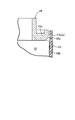
- First embodiment 3 is a cross-sectional view taken along line 3-3 of FIG.
- First embodiment 4 corresponds to FIG. (Second Embodiment)
- a battery module 11 used in an electric vehicle includes a plurality of rectangular parallelepiped (12 in the embodiment) battery cells 12... And two second holders 14 and 14 made of a synthetic resin and having a U-shaped cross section are laminated on the outer side in the stacking direction of the two battery cells 12 and 12 positioned at both ends in the stacking direction, Fastened in the stacking direction by fastening means (not shown).
- Each battery cell 12 is positioned so as to be sandwiched between the first holder 13 or the second holder 14 located on both sides thereof, and the first holder 13 and the second holders 14 and 14 have a certain positional relationship with each other. As a result, the shape of the battery module 11 is maintained.
- a plus terminal 12a and a minus terminal 12b are provided on the upper surface of each battery cell 12, and the plus terminals 12a and minus terminals 12b of the twelve battery cells 12 are electrically connected in series by the bus bar plate 15.
- the bus bar plate 15 is a member formed of a synthetic resin in a flat frame shape, and includes 11 first bus bars 16 made of a metal plate, and two second bus bars 17 and 17 made of a metal plate. Is provided.
- the twelve battery cells 12 are stacked such that the positive terminals 12a and the negative terminals 12b are alternately directed in opposite directions, and each first bus bar 16 includes two adjacent battery cells 12 and 12.
- the positive terminal 12a and the negative terminal 12b adjacent to each other in the stacking direction are connected to each other, and the two second bus bars 17 and 17 are positioned at the positive terminal 12a of the battery cell 12 positioned at one end in the stacking direction and the other end in the stacking direction. Connected to the negative terminal 12b of the battery cell 12 to be operated.
- a pair of boss portions 15 a, 15 a are provided at both ends in the longitudinal direction of the bus bar plate 15, and two bolts 18, 18 passing through these boss portions 15 a, 15 a are attached to the pair of second holders 14, 14.
- the bus bar plate 15 is assembled to the battery module 11 by screwing into the provided boss portions 14 a and 14 a.
- the bus bar plate 15 has a main body 15b extending in the longitudinal direction (stacking direction) at the center, two vertical frames 15c and 15c extending in parallel on the left and right sides of the main body 15b, the main body 15b and the vertical frames 15c, A total of 16 horizontal frames 15d for connecting 15c, and the first bus bar 16 and the second bus bars 17 and 17 in a space surrounded by the main body 15b, the vertical frames 15c and 15c, and the horizontal frame 15d. Is fixed. On the outer surface of each vertical frame 15c, eleven convex portions 15e are spaced from each other at a predetermined distance in the stacking direction.
- each first holder 13 includes a main body portion 13a sandwiched between adjacent battery cells 12 and 12, and a pair of flange portions 13b and 13b protruding from both ends of the main body portion 13a in the stacking direction.
- a recess 13c is formed in the upper part of the flange portion 13b.
- the eleven protrusions 15e provided on the vertical frame 15c on one side of the bus bar plate 15 at the same interval have the same shape, and all have a rectangular shape having a length a in the stacking direction. It is said.
- the eleven recesses 13c provided on the flanges 13b of the eleven first holders 13 are rectangular in shape in the stacking direction, but the length b in the stacking direction is different. . That is, among the eleven recesses 13c, the length b of one recess 13c (hereinafter referred to as the first recess 13c (a)) located at the center in the stacking direction is the shortest, and the protrusion 15e fits without a gap.
- the combined length (ie, length a).
- the length b of each of the five recesses 13c (hereinafter referred to as second recesses 13c (b)) located on both sides of the first recess 13c (a) in the stacking direction is far from the first recess 13c (a). It will be so long.
- the bus bar plate 15 is assembled to the upper surface of the battery module 11 in which the twelve battery cells 12, the eleventh first holders 13, and the two second holders 14, 14 are stacked.
- the positive terminals 12a and negative terminals 12b of the battery cells 12 can be connected at a time by the first bus bars 16 and the second bus bars 17 and 17.
- the left and right eleven convex portions 15 e projecting from the pair of vertical frames 15 c, 15 c of the bus bar plate 15 are replaced with a pair of flanges of the eleven first holders 13.
- Two bolts 18, 18 that are engaged with eleven concave portions 13 c... Formed on the left and right portions 13 b, 13 b and pass through the boss portions 15 a, 15 a provided at both ends of the main body portion 15 b of the bus bar plate 15 are What is necessary is just to screw in the boss
- the battery cells 12 are expanded due to a temperature change and the thickness has an error. May occur. Even if these individual errors are small, when the plurality of battery cells 12 and the plurality of first holders 13 are stacked and the error is accumulated, the convex portions 15e of the bus bar plate 15 and the first The positions of the recesses 13c of the holders 13 are shifted from each other, and the bus bar plate 15 may not be assembled smoothly.
- the length of the concave portions 13c may be made larger than the length of the convex portions 15e, but if this is done, the distance between all the convex portions 15e and all the concave portions 13c will be described. There is a possibility that rattling occurs and the bus bar plate 15 cannot be accurately positioned with respect to the battery module 11.
- the width a of the first recesses 13c (a) and 13c (a) of the first holder 13 located at the center in the stacking direction is the convexity of the bus bar plate 15 positioned at the center in the stacking direction. Since it corresponds to the width a of the portions 15e, 15e, the bus bar plate 15 can be accurately positioned in the stacking direction with respect to the battery module 11 by their engagement.
- the positions of the first holders 13 on both ends excluding the first holder 13 located in the center in the stacking direction vary in the stacking direction due to the dimensional error, and the amount of variation is far from the first holder 13 in the center. The bigger the thing.
- the second recesses 13c (b) of the first holders 13 ... farther from the center in the stacking direction have a larger width b in the stacking direction, so the second recesses 13c (b) ... Can be avoided from engaging with the convex portions 15e and the second concave portions 13c (b).
- the difference between the length a of the central first recess 13c (a) and the length b of the longest outer second recess 13c (b) is 1 About 5 mm.
- the first recess 13c (a) is disposed at the center in the longitudinal direction of the bus bar plate 15.
- the first recess 13c (a) is located at the end of the bus bar plate 15 in the longitudinal direction. You may arrange
- the first concave portion 13 (a) of the first holder 13 is provided on one end side of the bus bar plate 15, the positional error with respect to the convex portion 15e on the other end side of the bus bar plate 15 is the first implementation. Therefore, it is necessary to increase the length b of the second recess 13c (b) by that amount. Specifically, the difference between the length a of the first recess 13c (a) on one end side and the length b of the longest second recess 13c (b) on the other end side is the same as that of the first embodiment. Doubled to 3.0 mm.
- the first recess 13 (a) of the first holder 13 is provided at the center of the bus bar plate 15, the accumulated error can be dispersed in two directions.
- the length b of the second recess 13c (b) can be minimized.
- the lengths of the protrusions 15e on the bus bar plate 15 side are made constant, and the lengths of the recesses 13c on the first holder 13 side are made different, but the second embodiment is different. Then, the lengths of the recesses 13c on the first holder 13 side are made constant, and the lengths of the projections 15e on the bus bar plate 15 side are made different.
- the lengths b of the concave portions 13c of the first holders 13 are all the same, and the length a of the first convex portion 15e (a) at the center of the bus bar plate 15 is the same as the length b of the concave portions 13c.
- the outer second convex portion 15e (b) is positioned while the bus bar plate 15 is positioned in the longitudinal direction by the engagement between the central first convex portion 15e (a) and the concave portion 13c. , And the dimensional errors of the battery cells 12 and the first holders 13 can be absorbed by the dimensional difference between the recesses 13c.
- first convex portion 15e (a) is arranged at the center in the longitudinal direction of the bus bar plate 15, even if the length a of the longest first convex portion 15e (a) on the center side is shortened, the first convex portion 15e (a) The length a of the short second convex portion 15e (b) can be sufficiently secured, and thereby the length b of the concave portions 13c can be kept small.
- convex portions 15e are provided on the bus bar plate 15 side and concave portions 13c are provided on the first holder 13 side, but conversely, concave portions are provided on the bus bar plate 15 side and the first holder 13 is provided.
- a convex portion may be provided on the side.
- the recessed part 13c ... of embodiment is comprised by the hole which penetrates the flange part 13b ... of the 1st holder 13 ..., it is also possible to comprise the recessed part 13c ... by a hollow.
- the sixth convex portion 15e from the end portion becomes the central convex portion 15e
- the concave portion 13c engaged with the convex portion 15e becomes the first concave portion 13c (a).
- an even number of convex portions 15e ... are provided on one side of the bus bar plate 15
- the two recesses 13c, 13c that engage with the first recesses 13c (a), 13c (a) may be used. The same can be said for the second embodiment only by replacing the relationship between the convex portion 15e and the concave portion 13c.
- the length b of the second recesses 13c (b) is increased as the distance from the center of the bus bar plate 15 increases.
- the length b of the second recesses 13c (b) As long as it is longer than the length a of the first recess 13c (a), they may all be the same. The same can be said for the second embodiment only by replacing the relationship between the convex portion 15e and the concave portion 13c.
Landscapes
- Engineering & Computer Science (AREA)
- Power Engineering (AREA)
- Life Sciences & Earth Sciences (AREA)
- Sustainable Development (AREA)
- Sustainable Energy (AREA)
- Transportation (AREA)
- Mechanical Engineering (AREA)
- Chemical & Material Sciences (AREA)
- Chemical Kinetics & Catalysis (AREA)
- Electrochemistry (AREA)
- General Chemical & Material Sciences (AREA)
- Connection Of Batteries Or Terminals (AREA)
- Battery Mounting, Suspending (AREA)
Abstract
Description
12a プラス端子(端子)
12b マイナス端子(端子)
13 第1ホルダ(ホルダ)
13c 凹部
13c(a) 第1凹部
13c(b) 第2凹部
16 第1バスバー(バスバー)
17 第2バスバー(バスバー)
15 バスバープレート
15e 凸部
15e(a) 第1凸部
13e(b) 第2凸部 12
12b Negative terminal (terminal)
13 First holder (holder)
13c
17 Second bus bar (bus bar)
15 Busbar
Claims (6)
- ホルダ(13)を挟んで積層された複数のバッテリセル(12)と、前記複数のバッテリセル(12)の端子(12a,12b)どうしを電気的に接続する複数のバスバー(16,17)を有するバスバープレート(15)とを備え、前記複数のホルダ(13)および前記バスバープレート(15)の一方に前記積層方向に離間して設けられた複数の凸部(15e)と、前記複数のホルダ(13)および前記バスバープレート(15)の他方に前記積層方向に離間して設けられた複数の凹部(13c)との係合により、前記複数のホルダ(13)と前記バスバープレート(15)とを結合するバッテリモジュールであって、
前記複数の凸部(15e)の前記積層方向の長さは同一であり、前記複数の凹部(13c)は、第1凹部(13c(a))と該第1凹部(13c(a))よりも前記積層方向の長さが長い第2凹部(13c(b))とから構成されることを特徴とするバッテリモジュール。 A plurality of battery cells (12) stacked with a holder (13) in between, and a plurality of bus bars (16, 17) electrically connecting terminals (12a, 12b) of the plurality of battery cells (12). A plurality of protrusions (15e) provided on one of the plurality of holders (13) and the bus bar plate (15) so as to be spaced apart from each other in the stacking direction, and the plurality of holders (13) and the bus bar plate (15) are engaged with a plurality of recesses (13c) provided apart from each other in the stacking direction, and the plurality of holders (13) and the bus bar plate (15) A battery module that combines
The plurality of convex portions (15e) have the same length in the stacking direction, and the plurality of concave portions (13c) are formed by the first concave portion (13c (a)) and the first concave portion (13c (a)). And a second recess (13c (b)) having a long length in the stacking direction. - 前記第1凹部(13c(a))は前記積層方向の中央部側に位置し、前記第2凹部(13c(b))は前記積層方向の両端部側に位置することを特徴とする、請求項1に記載のバッテリモジュール。 The first recess (13c (a)) is located on the center side in the stacking direction, and the second recess (13c (b)) is located on both end sides in the stacking direction. Item 2. The battery module according to Item 1.
- 前記第2凹部(13c(b))は、前記第1凹部(13c(a))から遠いものほど前記積層方向の長さが長いことを特徴とする、請求項2に記載のバッテリモジュール。 The battery module according to claim 2, wherein the second recess (13c (b)) has a longer length in the stacking direction as it is farther from the first recess (13c (a)).
- ホルダ(13)を挟んで積層された複数のバッテリセル(12)と、前記複数のバッテリセル(12)の端子(12a,12b)どうしを電気的に接続する複数のバスバー(16,17)を有するバスバープレート(15)とを備え、前記複数のホルダ(13)および前記バスバープレート(15)の一方に前記積層方向に離間して設けられた複数の凸部(15e)と、前記複数のホルダ(13)および前記バスバープレート(15)の他方に前記積層方向に離間して設けられた複数の凹部(13c)との係合により、前記複数のホルダ(13)と前記バスバープレート(15)とを結合するバッテリモジュールであって、
前記複数の凹部(13c)の前記積層方向の長さは同一であり、前記複数の凸部(15e)は、第1凸部(15e(a))と該第1凸部(15e(a))よりも前記積層方向の長さが短い第2凸部(15e(b))とから構成されることを特徴とするバッテリモジュール。 A plurality of battery cells (12) stacked with a holder (13) in between, and a plurality of bus bars (16, 17) electrically connecting terminals (12a, 12b) of the plurality of battery cells (12). A plurality of protrusions (15e) provided on one of the plurality of holders (13) and the bus bar plate (15) so as to be spaced apart from each other in the stacking direction, and the plurality of holders (13) and the bus bar plate (15) are engaged with a plurality of recesses (13c) provided apart from each other in the stacking direction, and the plurality of holders (13) and the bus bar plate (15) A battery module that combines
The plurality of concave portions (13c) have the same length in the stacking direction, and the plurality of convex portions (15e) includes the first convex portion (15e (a)) and the first convex portion (15e (a)). ) And the second convex part (15e (b)) having a shorter length in the stacking direction. - 前記第1凸部(15e(a))は前記積層方向の中央部側に位置し、前記第2凸部(15e(b))は前記積層方向の両端部側に位置することを特徴とする、請求項4に記載のバッテリモジュール。 The first convex portion (15e (a)) is located on the center side in the stacking direction, and the second convex portion (15e (b)) is located on both end sides in the stacking direction. The battery module according to claim 4.
- 前記第2凸部(15e(b))は、前記第1凸部(15e(a))から遠いものほど前記積層方向の長さが短いことを特徴とする、請求項5に記載のバッテリモジュール。 6. The battery module according to claim 5, wherein the second convex portion (15 e (b)) has a shorter length in the stacking direction as it is farther from the first convex portion (15 e (a)). 7. .
Priority Applications (2)
| Application Number | Priority Date | Filing Date | Title |
|---|---|---|---|
| JP2013548271A JP5758502B2 (en) | 2011-12-09 | 2012-12-05 | Battery module |
| US14/362,670 US10074844B2 (en) | 2011-12-09 | 2012-12-05 | Battery module |
Applications Claiming Priority (2)
| Application Number | Priority Date | Filing Date | Title |
|---|---|---|---|
| JP2011-269838 | 2011-12-09 | ||
| JP2011269838 | 2011-12-09 |
Publications (1)
| Publication Number | Publication Date |
|---|---|
| WO2013084941A1 true WO2013084941A1 (en) | 2013-06-13 |
Family
ID=48574299
Family Applications (1)
| Application Number | Title | Priority Date | Filing Date |
|---|---|---|---|
| PCT/JP2012/081511 WO2013084941A1 (en) | 2011-12-09 | 2012-12-05 | Battery module |
Country Status (3)
| Country | Link |
|---|---|
| US (1) | US10074844B2 (en) |
| JP (1) | JP5758502B2 (en) |
| WO (1) | WO2013084941A1 (en) |
Cited By (15)
| Publication number | Priority date | Publication date | Assignee | Title |
|---|---|---|---|---|
| WO2014034079A1 (en) * | 2012-08-30 | 2014-03-06 | 三洋電機株式会社 | Power source device, vehicle provided with power source device, and power storage device |
| CN104716378A (en) * | 2013-12-17 | 2015-06-17 | 三星Sdi株式会社 | Battery module |
| WO2015170580A1 (en) * | 2014-05-07 | 2015-11-12 | 株式会社 豊田自動織機 | Battery module |
| WO2016190075A1 (en) * | 2015-05-28 | 2016-12-01 | 株式会社オートネットワーク技術研究所 | Power storage module |
| WO2017006763A1 (en) * | 2015-07-09 | 2017-01-12 | 日立オートモティブシステムズ株式会社 | Cell module |
| US20170125753A1 (en) * | 2015-11-02 | 2017-05-04 | Samsung Sdi Co., Ltd. | Rechargeable battery module |
| CN108198977A (en) * | 2017-12-30 | 2018-06-22 | 王思瑶 | A kind of new energy electric motor vehicle battery pack |
| US10096868B2 (en) | 2016-02-23 | 2018-10-09 | Gs Yuasa International Ltd. | Energy storage apparatus and method of manufacturing energy storage apparatus |
| JP2019029309A (en) * | 2017-08-03 | 2019-02-21 | 株式会社Gsユアサ | Power storage device |
| US10461292B2 (en) | 2015-11-16 | 2019-10-29 | Gs Yuasa International Ltd. | Energy storage apparatus and cover member |
| WO2020213188A1 (en) * | 2019-04-19 | 2020-10-22 | 株式会社 東芝 | Battery module |
| WO2020235279A1 (en) * | 2019-05-22 | 2020-11-26 | 三洋電機株式会社 | Bus bar plate |
| CN112310534A (en) * | 2019-12-27 | 2021-02-02 | 宁德时代新能源科技股份有限公司 | Separator assembly, battery module, battery pack, device, and manufacturing method |
| WO2021129136A1 (en) * | 2019-12-27 | 2021-07-01 | 宁德时代新能源科技股份有限公司 | Connection assembly, battery module, battery pack, device, and manufacturing method |
| US11996575B2 (en) | 2018-06-22 | 2024-05-28 | Gs Yuasa International Ltd. | Energy storage apparatus |
Families Citing this family (9)
| Publication number | Priority date | Publication date | Assignee | Title |
|---|---|---|---|---|
| JP6822048B2 (en) | 2016-10-12 | 2021-01-27 | 株式会社Gsユアサ | Power storage device |
| JP7028105B2 (en) * | 2018-08-29 | 2022-03-02 | 住友電装株式会社 | Battery wiring module |
| US11271272B2 (en) | 2018-10-26 | 2022-03-08 | Samsung Sdi Co., Ltd. | Battery module |
| CA187846S (en) * | 2018-12-28 | 2020-07-20 | Sungrow Power Supply Co Ltd | Inverter |
| USD906961S1 (en) * | 2019-01-31 | 2021-01-05 | Mitsubishi Electric Corporation | Servo amplifier |
| USD906960S1 (en) | 2019-01-31 | 2021-01-05 | Mitsubishi Electric Corporation | Servo amplifier |
| JP1647700S (en) * | 2019-01-31 | 2019-12-09 | ||
| CN111540944A (en) * | 2019-09-20 | 2020-08-14 | 杭州乾代科技有限公司 | Assembled lithium battery module |
| US11721875B2 (en) * | 2020-03-02 | 2023-08-08 | Toyota Motor Engineering & Manufacturing North America, Inc. | Battery pack assemblies having elongated terminal connectors and vehicles having the same |
Citations (7)
| Publication number | Priority date | Publication date | Assignee | Title |
|---|---|---|---|---|
| JP2000149909A (en) * | 1998-09-09 | 2000-05-30 | Yazaki Corp | Battery connecting plate |
| JP2005322647A (en) * | 2004-05-04 | 2005-11-17 | Samsung Sdi Co Ltd | Secondary battery module |
| JP2009043637A (en) * | 2007-08-10 | 2009-02-26 | Yazaki Corp | Power supply device |
| JP2009048973A (en) * | 2007-08-23 | 2009-03-05 | Yazaki Corp | Power supply device |
| JP2011228218A (en) * | 2010-04-22 | 2011-11-10 | Yazaki Corp | Battery connection plate |
| WO2011142201A1 (en) * | 2010-05-13 | 2011-11-17 | 矢崎総業株式会社 | Cover member and power supply device equipped with this cover member |
| JP2011249303A (en) * | 2010-05-24 | 2011-12-08 | Sb Limotive Co Ltd | Battery module |
Family Cites Families (1)
| Publication number | Priority date | Publication date | Assignee | Title |
|---|---|---|---|---|
| JP5088071B2 (en) | 2007-09-28 | 2012-12-05 | 三菱自動車工業株式会社 | Battery unit for electric vehicles |
-
2012
- 2012-12-05 US US14/362,670 patent/US10074844B2/en active Active
- 2012-12-05 WO PCT/JP2012/081511 patent/WO2013084941A1/en active Application Filing
- 2012-12-05 JP JP2013548271A patent/JP5758502B2/en not_active Expired - Fee Related
Patent Citations (7)
| Publication number | Priority date | Publication date | Assignee | Title |
|---|---|---|---|---|
| JP2000149909A (en) * | 1998-09-09 | 2000-05-30 | Yazaki Corp | Battery connecting plate |
| JP2005322647A (en) * | 2004-05-04 | 2005-11-17 | Samsung Sdi Co Ltd | Secondary battery module |
| JP2009043637A (en) * | 2007-08-10 | 2009-02-26 | Yazaki Corp | Power supply device |
| JP2009048973A (en) * | 2007-08-23 | 2009-03-05 | Yazaki Corp | Power supply device |
| JP2011228218A (en) * | 2010-04-22 | 2011-11-10 | Yazaki Corp | Battery connection plate |
| WO2011142201A1 (en) * | 2010-05-13 | 2011-11-17 | 矢崎総業株式会社 | Cover member and power supply device equipped with this cover member |
| JP2011249303A (en) * | 2010-05-24 | 2011-12-08 | Sb Limotive Co Ltd | Battery module |
Cited By (27)
| Publication number | Priority date | Publication date | Assignee | Title |
|---|---|---|---|---|
| US9616766B2 (en) | 2012-08-30 | 2017-04-11 | Sanyo Electric Co., Ltd. | Power source device, vehicle provided with power source device, and power storage device |
| WO2014034079A1 (en) * | 2012-08-30 | 2014-03-06 | 三洋電機株式会社 | Power source device, vehicle provided with power source device, and power storage device |
| CN104716378A (en) * | 2013-12-17 | 2015-06-17 | 三星Sdi株式会社 | Battery module |
| WO2015170580A1 (en) * | 2014-05-07 | 2015-11-12 | 株式会社 豊田自動織機 | Battery module |
| JP2015213039A (en) * | 2014-05-07 | 2015-11-26 | 株式会社豊田自動織機 | Battery module |
| US9716255B2 (en) | 2014-05-07 | 2017-07-25 | Kabushiki Kaisha Toyota Jidoshokki | Battery module |
| WO2016190075A1 (en) * | 2015-05-28 | 2016-12-01 | 株式会社オートネットワーク技術研究所 | Power storage module |
| JP2016225054A (en) * | 2015-05-28 | 2016-12-28 | 株式会社オートネットワーク技術研究所 | Power storage module |
| CN107615519A (en) * | 2015-05-28 | 2018-01-19 | 株式会社自动网络技术研究所 | Power storage module |
| WO2017006763A1 (en) * | 2015-07-09 | 2017-01-12 | 日立オートモティブシステムズ株式会社 | Cell module |
| JPWO2017006763A1 (en) * | 2015-07-09 | 2018-03-01 | 日立オートモティブシステムズ株式会社 | Battery module |
| US20170125753A1 (en) * | 2015-11-02 | 2017-05-04 | Samsung Sdi Co., Ltd. | Rechargeable battery module |
| US10177353B2 (en) * | 2015-11-02 | 2019-01-08 | Samsung Sdi Co., Ltd. | Rechargeable battery module |
| US10461292B2 (en) | 2015-11-16 | 2019-10-29 | Gs Yuasa International Ltd. | Energy storage apparatus and cover member |
| US10096868B2 (en) | 2016-02-23 | 2018-10-09 | Gs Yuasa International Ltd. | Energy storage apparatus and method of manufacturing energy storage apparatus |
| JP2019029309A (en) * | 2017-08-03 | 2019-02-21 | 株式会社Gsユアサ | Power storage device |
| CN108198977A (en) * | 2017-12-30 | 2018-06-22 | 王思瑶 | A kind of new energy electric motor vehicle battery pack |
| US11996575B2 (en) | 2018-06-22 | 2024-05-28 | Gs Yuasa International Ltd. | Energy storage apparatus |
| WO2020213188A1 (en) * | 2019-04-19 | 2020-10-22 | 株式会社 東芝 | Battery module |
| JP2020177842A (en) * | 2019-04-19 | 2020-10-29 | 株式会社東芝 | Battery module |
| JP7242396B2 (en) | 2019-04-19 | 2023-03-20 | 株式会社東芝 | battery module |
| WO2020235279A1 (en) * | 2019-05-22 | 2020-11-26 | 三洋電機株式会社 | Bus bar plate |
| JP7458386B2 (en) | 2019-05-22 | 2024-03-29 | 三洋電機株式会社 | busbar plate |
| CN112310534A (en) * | 2019-12-27 | 2021-02-02 | 宁德时代新能源科技股份有限公司 | Separator assembly, battery module, battery pack, device, and manufacturing method |
| WO2021129136A1 (en) * | 2019-12-27 | 2021-07-01 | 宁德时代新能源科技股份有限公司 | Connection assembly, battery module, battery pack, device, and manufacturing method |
| US11605865B2 (en) | 2019-12-27 | 2023-03-14 | Contemporary Amperex Technology Co., Limited | Separator assembly, battery module, battery pack, apparatus and manufacturing method |
| US11616275B2 (en) | 2019-12-27 | 2023-03-28 | Contemporary Amperex Technology Co., Limited | Connecting assembly, battery module, battery pack, device, and manufacturing method |
Also Published As
| Publication number | Publication date |
|---|---|
| JP5758502B2 (en) | 2015-08-05 |
| US10074844B2 (en) | 2018-09-11 |
| JPWO2013084941A1 (en) | 2015-04-27 |
| US20140335393A1 (en) | 2014-11-13 |
Similar Documents
| Publication | Publication Date | Title |
|---|---|---|
| JP5758502B2 (en) | Battery module | |
| US8512889B1 (en) | Battery module | |
| EP2515360B1 (en) | Battery module | |
| JP5544931B2 (en) | Laminated cell battery structure | |
| JP6622163B2 (en) | Battery module voltage detector and battery pack | |
| US9929427B2 (en) | Battery module having reinforcing barrier with metal member | |
| JP6070999B2 (en) | Power storage module | |
| JP6670272B2 (en) | Battery module | |
| US20140356690A1 (en) | Battery module | |
| JP2013122819A (en) | Battery module unit | |
| JP2012256466A (en) | Battery module | |
| JP2019075246A (en) | Battery module | |
| JP2011198660A (en) | Battery pack | |
| JP6676598B2 (en) | Battery module | |
| US10122006B2 (en) | Connection module | |
| JP2015099647A (en) | Power storage module and power storage cell | |
| US20130323576A1 (en) | Power storage device | |
| JP2014232633A (en) | Bus bar module and power unit | |
| JP2015050067A (en) | Electrical storage device | |
| JP6594382B2 (en) | Bus bar module and battery pack | |
| JP5880722B2 (en) | Assembled battery | |
| KR101907723B1 (en) | Electrode constituent for battery module | |
| KR101503983B1 (en) | Housing structure and housing method of Battery Module Assembly | |
| WO2013021592A1 (en) | Battery pack | |
| JP2013073918A (en) | Battery pack |
Legal Events
| Date | Code | Title | Description |
|---|---|---|---|
| 121 | Ep: the epo has been informed by wipo that ep was designated in this application |
Ref document number: 12854718 Country of ref document: EP Kind code of ref document: A1 |
|
| ENP | Entry into the national phase |
Ref document number: 2013548271 Country of ref document: JP Kind code of ref document: A |
|
| WWE | Wipo information: entry into national phase |
Ref document number: 14362670 Country of ref document: US |
|
| NENP | Non-entry into the national phase |
Ref country code: DE |
|
| 122 | Ep: pct application non-entry in european phase |
Ref document number: 12854718 Country of ref document: EP Kind code of ref document: A1 |