WO2013084811A1 - 耳孔装着型収音装置、信号処理装置、収音方法 - Google Patents
耳孔装着型収音装置、信号処理装置、収音方法 Download PDFInfo
- Publication number
- WO2013084811A1 WO2013084811A1 PCT/JP2012/081055 JP2012081055W WO2013084811A1 WO 2013084811 A1 WO2013084811 A1 WO 2013084811A1 JP 2012081055 W JP2012081055 W JP 2012081055W WO 2013084811 A1 WO2013084811 A1 WO 2013084811A1
- Authority
- WO
- WIPO (PCT)
- Prior art keywords
- sound
- signal
- microphone
- noise canceling
- noise
- Prior art date
- Legal status (The legal status is an assumption and is not a legal conclusion. Google has not performed a legal analysis and makes no representation as to the accuracy of the status listed.)
- Ceased
Links
Images


Classifications
-
- G—PHYSICS
- G10—MUSICAL INSTRUMENTS; ACOUSTICS
- G10K—SOUND-PRODUCING DEVICES; METHODS OR DEVICES FOR PROTECTING AGAINST, OR FOR DAMPING, NOISE OR OTHER ACOUSTIC WAVES IN GENERAL; ACOUSTICS NOT OTHERWISE PROVIDED FOR
- G10K11/00—Methods or devices for transmitting, conducting or directing sound in general; Methods or devices for protecting against, or for damping, noise or other acoustic waves in general
- G10K11/16—Methods or devices for protecting against, or for damping, noise or other acoustic waves in general
- G10K11/175—Methods or devices for protecting against, or for damping, noise or other acoustic waves in general using interference effects; Masking sound
- G10K11/178—Methods or devices for protecting against, or for damping, noise or other acoustic waves in general using interference effects; Masking sound by electro-acoustically regenerating the original acoustic waves in anti-phase
- G10K11/1785—Methods, e.g. algorithms; Devices
- G10K11/17857—Geometric disposition, e.g. placement of microphones
-
- G—PHYSICS
- G10—MUSICAL INSTRUMENTS; ACOUSTICS
- G10K—SOUND-PRODUCING DEVICES; METHODS OR DEVICES FOR PROTECTING AGAINST, OR FOR DAMPING, NOISE OR OTHER ACOUSTIC WAVES IN GENERAL; ACOUSTICS NOT OTHERWISE PROVIDED FOR
- G10K11/00—Methods or devices for transmitting, conducting or directing sound in general; Methods or devices for protecting against, or for damping, noise or other acoustic waves in general
- G10K11/16—Methods or devices for protecting against, or for damping, noise or other acoustic waves in general
- G10K11/175—Methods or devices for protecting against, or for damping, noise or other acoustic waves in general using interference effects; Masking sound
- G10K11/178—Methods or devices for protecting against, or for damping, noise or other acoustic waves in general using interference effects; Masking sound by electro-acoustically regenerating the original acoustic waves in anti-phase
- G10K11/1787—General system configurations
- G10K11/17873—General system configurations using a reference signal without an error signal, e.g. pure feedforward
-
- G—PHYSICS
- G10—MUSICAL INSTRUMENTS; ACOUSTICS
- G10K—SOUND-PRODUCING DEVICES; METHODS OR DEVICES FOR PROTECTING AGAINST, OR FOR DAMPING, NOISE OR OTHER ACOUSTIC WAVES IN GENERAL; ACOUSTICS NOT OTHERWISE PROVIDED FOR
- G10K11/00—Methods or devices for transmitting, conducting or directing sound in general; Methods or devices for protecting against, or for damping, noise or other acoustic waves in general
- G10K11/16—Methods or devices for protecting against, or for damping, noise or other acoustic waves in general
- G10K11/175—Methods or devices for protecting against, or for damping, noise or other acoustic waves in general using interference effects; Masking sound
- G10K11/178—Methods or devices for protecting against, or for damping, noise or other acoustic waves in general using interference effects; Masking sound by electro-acoustically regenerating the original acoustic waves in anti-phase
- G10K11/1787—General system configurations
- G10K11/17885—General system configurations additionally using a desired external signal, e.g. pass-through audio such as music or speech
-
- G—PHYSICS
- G10—MUSICAL INSTRUMENTS; ACOUSTICS
- G10L—SPEECH ANALYSIS TECHNIQUES OR SPEECH SYNTHESIS; SPEECH RECOGNITION; SPEECH OR VOICE PROCESSING TECHNIQUES; SPEECH OR AUDIO CODING OR DECODING
- G10L21/00—Speech or voice signal processing techniques to produce another audible or non-audible signal, e.g. visual or tactile, in order to modify its quality or its intelligibility
- G10L21/02—Speech enhancement, e.g. noise reduction or echo cancellation
- G10L21/0208—Noise filtering
-
- H—ELECTRICITY
- H04—ELECTRIC COMMUNICATION TECHNIQUE
- H04R—LOUDSPEAKERS, MICROPHONES, GRAMOPHONE PICK-UPS OR LIKE ACOUSTIC ELECTROMECHANICAL TRANSDUCERS; DEAF-AID SETS; PUBLIC ADDRESS SYSTEMS
- H04R1/00—Details of transducers, loudspeakers or microphones
- H04R1/10—Earpieces; Attachments therefor ; Earphones; Monophonic headphones
- H04R1/1083—Reduction of ambient noise
-
- G—PHYSICS
- G10—MUSICAL INSTRUMENTS; ACOUSTICS
- G10K—SOUND-PRODUCING DEVICES; METHODS OR DEVICES FOR PROTECTING AGAINST, OR FOR DAMPING, NOISE OR OTHER ACOUSTIC WAVES IN GENERAL; ACOUSTICS NOT OTHERWISE PROVIDED FOR
- G10K2210/00—Details of active noise control [ANC] covered by G10K11/178 but not provided for in any of its subgroups
- G10K2210/10—Applications
- G10K2210/108—Communication systems, e.g. where useful sound is kept and noise is cancelled
- G10K2210/1081—Earphones, e.g. for telephones, ear protectors or headsets
-
- G—PHYSICS
- G10—MUSICAL INSTRUMENTS; ACOUSTICS
- G10K—SOUND-PRODUCING DEVICES; METHODS OR DEVICES FOR PROTECTING AGAINST, OR FOR DAMPING, NOISE OR OTHER ACOUSTIC WAVES IN GENERAL; ACOUSTICS NOT OTHERWISE PROVIDED FOR
- G10K2210/00—Details of active noise control [ANC] covered by G10K11/178 but not provided for in any of its subgroups
- G10K2210/30—Means
- G10K2210/301—Computational
- G10K2210/3026—Feedback
-
- G—PHYSICS
- G10—MUSICAL INSTRUMENTS; ACOUSTICS
- G10K—SOUND-PRODUCING DEVICES; METHODS OR DEVICES FOR PROTECTING AGAINST, OR FOR DAMPING, NOISE OR OTHER ACOUSTIC WAVES IN GENERAL; ACOUSTICS NOT OTHERWISE PROVIDED FOR
- G10K2210/00—Details of active noise control [ANC] covered by G10K11/178 but not provided for in any of its subgroups
- G10K2210/30—Means
- G10K2210/301—Computational
- G10K2210/3027—Feedforward
-
- H—ELECTRICITY
- H04—ELECTRIC COMMUNICATION TECHNIQUE
- H04R—LOUDSPEAKERS, MICROPHONES, GRAMOPHONE PICK-UPS OR LIKE ACOUSTIC ELECTROMECHANICAL TRANSDUCERS; DEAF-AID SETS; PUBLIC ADDRESS SYSTEMS
- H04R1/00—Details of transducers, loudspeakers or microphones
- H04R1/10—Earpieces; Attachments therefor ; Earphones; Monophonic headphones
- H04R1/1016—Earpieces of the intra-aural type
-
- H—ELECTRICITY
- H04—ELECTRIC COMMUNICATION TECHNIQUE
- H04R—LOUDSPEAKERS, MICROPHONES, GRAMOPHONE PICK-UPS OR LIKE ACOUSTIC ELECTROMECHANICAL TRANSDUCERS; DEAF-AID SETS; PUBLIC ADDRESS SYSTEMS
- H04R3/00—Circuits for transducers, loudspeakers or microphones
-
- H—ELECTRICITY
- H04—ELECTRIC COMMUNICATION TECHNIQUE
- H04R—LOUDSPEAKERS, MICROPHONES, GRAMOPHONE PICK-UPS OR LIKE ACOUSTIC ELECTROMECHANICAL TRANSDUCERS; DEAF-AID SETS; PUBLIC ADDRESS SYSTEMS
- H04R5/00—Stereophonic arrangements
- H04R5/033—Headphones for stereophonic communication
-
- H—ELECTRICITY
- H04—ELECTRIC COMMUNICATION TECHNIQUE
- H04R—LOUDSPEAKERS, MICROPHONES, GRAMOPHONE PICK-UPS OR LIKE ACOUSTIC ELECTROMECHANICAL TRANSDUCERS; DEAF-AID SETS; PUBLIC ADDRESS SYSTEMS
- H04R5/00—Stereophonic arrangements
- H04R5/04—Circuit arrangements, e.g. for selective connection of amplifier inputs/outputs to loudspeakers, for loudspeaker detection, or for adaptation of settings to personal preferences or hearing impairments
Definitions
- This technique is a signal for performing signal processing on a sound collecting device having an ear hole mounting type sound collecting device having a mounting part configured to be at least partially insertable into the ear hole part, and an internal microphone provided in the mounting part.
- the present invention relates to a processing apparatus and a sound collection method.
- an earphone microphone (earphone with a built-in microphone) for enabling listening to received sound and collecting sound is used.
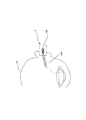
- FIG. 13 shows an example of a general earphone microphone (hereinafter referred to as a conventional earphone microphone 100) that is widely used at present.
- a conventional earphone microphone 100 is provided with an earphone unit 101 for listening to a received sound and a microphone 102A for collecting the uttered sound.
- Earphone unit 101 is configured to be worn on the ear of wearer H, and has a built-in speaker for outputting a received sound.
- a cord upper housing 102 is formed on a cord for transmitting a signal to the earphone unit 101, and a microphone 102 ⁇ / b> A is formed in the cord upper housing 102.
- the uttered sound emitted from the wearer (speaker) reaches the microphone 102A via the outside (outside air) and is collected.
- the microphone 102A for collecting the uttered sound is exposed to the outside. That is, the microphone 102A is in direct contact with external noise (environmental noise). For this reason, in the conventional earphone microphone 100, ambient noise is picked up relatively loudly together with the uttered sound, and the S / N (signal-to-noise ratio) of the utterance signal tends to decrease. That is, as a result, it is difficult for the other party of the call to hear the speech from the wearer H.
- noise reduction processing such as SS method (SS: Spectrum Subtraction) on the uttered sound collection signal.
- SS method Spectrum Subtraction
- noise reduction processing relatively large processing resources are required, which is disadvantageous in terms of product cost and power consumption.
- noise reduction processing involving nonlinear processing on the frequency axis as in the SS method generally has a problem of deterioration in sound quality after processing.
- the present technology has been made in view of the above-mentioned problems, and the problem is to realize a sound pickup with a good S / N with reduced influence of noise, without using noise reduction processing.
- the present technology is configured as follows as an ear hole mounting type sound pickup device. That is, at least a part of the mounting part is configured to be insertable into the ear canal part, and the mounting part is configured so that a substantially sealed internal space connected to the external auditory canal is formed inside the ear hole part in a mounted state. Is provided.
- an internal microphone is provided that is disposed in the internal space of the mounting portion and picks up the uttered sound that is emitted by the wearer and propagates through the ear canal in a state of being attached to the ear canal portion.
- an equalizing processing unit that performs high-frequency emphasizing equalizing processing on the sound-collected signal from the internal microphone is provided.
- positioned in the said internal space of the said mounting part is provided.
- a noise canceling processing unit for outputting a noise canceling sound for reducing noise propagating to the internal space of the mounting unit from the speaker based on a sound pickup signal from a microphone provided for the mounting unit. I was prepared to.
- the microphone that collects the uttered sound (the internal microphone) is substantially sealed from the outside, and is installed in a space that communicates with the ear canal of the wearer (speaker). By being installed in a space sealed from the outside, the influence of noise can be effectively reduced.
- the conventional earphone microphone (FIG. 13) that collects the utterance sound emitted from the wearer and propagating in the outside world is collected. Can pick up the utterance sound with good S / N.
- the noise canceling processing unit noise propagating to the internal space in which the internal microphone is arranged is reduced. Thereby, further S / N improvement of an utterance sound collection signal is achieved.
- the equalizing processing unit is provided to reduce the booming sound that occurs when the uttered sound via the ear canal is picked up.
- the present technology it is possible to collect a speech sound with better S / N than a conventional earphone microphone that collects a speech sound propagating in the outside world. Further, according to the present technology, noise reduction processing for a collected sound signal can be made unnecessary, and as a result, increase in signal processing resources can be prevented, which is advantageous in terms of product cost and power consumption.
- FIG. 1 It is a figure for demonstrating the structure of the mounting part with which the sound collection system of embodiment is provided. It is the figure which showed typically the mode of the sound collection of the speech sound by the sound collection system of embodiment. It is a figure for demonstrating the structure of the signal processing system for sound quality improvement. It is a figure for demonstrating the specific frequency characteristic which should be set to an equalizer for sound quality improvement. It is explanatory drawing about a compressor process. It is the figure which showed the structure of the sound collection system as Example 1.
- FIG. It is the figure which showed the example of a structure of each of "integrated type" and "separation type" which the sound collection system of embodiment can take. It is the figure which showed the structure (at the time of call mode) of the sound collection system as Example 2.
- FIG. 1 It is the figure which showed the example of a structure of each of "integrated type" and "separation type" which the sound collection system of embodiment can take. It is the figure which showed the structure (at the time of call mode) of the sound
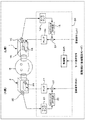
- FIG. It is the figure which showed the structure (at the time of music listening mode) of the sound collection system as Example 2.
- FIG. It is the figure which showed the structure of the sound collection system as Example 3.
- FIG. It is the figure which showed the structure of the sound collection system as Example 4.
- FIG. It is the figure which showed the structure of the sound collection system as Example 5.
- FIG. It is the figure which showed the structural example of the conventional earphone microphone.
- FIG. 1 is a diagram for describing a structure of a mounting portion 1 included in a sound collection system as an embodiment according to the present technology. Specifically, A in FIG. 1 represents a perspective view of the wearing portion 1, and B in FIG. 1 represents the ear canal HA and ear canal HB of the wearer H in the wearing state of the wearer (speaker) H. The relationship with the mounting part 1 is represented by a sectional view.
- the wearing unit 1 is provided with an internal microphone 1 ⁇ / b> B in order to pick up the utterance sound of the wearer (speaker) H.
- a MEMS microphone MEMS: Micro Electro Mechanical Systems
- the internal microphone 1B is adopted as the internal microphone 1B in consideration of the arrangement space.
- the outer shape of the mounting portion 1 is configured such that at least a part of the mounting portion 1 can be inserted into the ear hole portion of the wearer H so that the mounting portion 1 can be worn on the ear portion of the wearer H.
- the mounting part 1 in this case is formed with an ear hole insertion part 1A that is shaped to be inserted into the ear hole part HB of the wearer H, and the ear hole insertion part 1A corresponds to the ear hole part HB.
- the wearing part 1 is put into a wearing state with respect to the ear part of the wearer H.
- the mounting part 1 is comprised so that the internal space 1V connected with the external ear canal HA of the wearer H may be formed as shown to B of FIG.
- the ear hole insertion portion 1A of the mounting portion 1 is covered with an elastic material on the surface portion, similarly to the ear hole insertion portion of the canal type earphone portion, and is in close contact with the ear hole portion HB at the time of mounting. It is comprised so that can be obtained.
- the internal space 1V is a substantially sealed space from the outside.
- the internal microphone 1B is arranged in the internal space 1V.
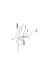
- FIG. 2 is a diagram schematically showing a state of sound collection by the sound collection system according to the embodiment having the mounting portion 1.
- the noise that propagates from the outside of the housing can be prevented. Since the sound insulation property of the microphone is sufficiently enhanced, the mixing of noise into the internal microphone 1B is sufficiently suppressed. That is, as a result, the utterance sound can be collected with a better S / N (signal-to-noise ratio) than the conventional earphone microphone 100 (see FIG. 13) that collects the utterance sound via the outside world. Note that the sound insulation at this time is not limited as long as it can cover at least the band of noise intended to be suppressed.
- the gain (response) in the low frequency is larger in the external auditory canal HA than in the normal free space.
- the response characteristic of the low range becomes relatively large. Due to this influence, the transmitted voice based on the collected sound signal from the internal microphone 1B becomes a sound that is confined to the low frequency range, and it becomes somewhat difficult for the other party of the call to hear.
- signal processing means as an equalizer (EQ) as shown in FIG.
- EQ equalizer
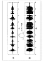
- FIG. 4 is a diagram for explaining specific frequency characteristics to be set in the equalizer 11.
- a specified conversation sequence is collected by a microphone installed in the outside of the wearing unit 1 in a no-noise state.
- the frequency characteristics of the collected sound signal (a set of ⁇ plots and broken lines in the figure) and the same conversation sequence are collected by the internal microphone 1B in the internal space 1V connected to the ear canal HA in the same noise-free state.
- the frequency characteristics of the collected sound signal at the time of the sound ( ⁇ plot and a set of alternate long and short dash lines) are shown in comparison. In this figure, the frequency characteristic shows a time-averaged value on the frequency axis.
- the diaphragm of the internal microphone 1B is compared with the external environment as an unsealed environment.
- the amplitude will be large.
- a larger microphone output voltage can be obtained in the lower range than a microphone installed outside.
- the sound pickup signal ( ⁇ & alternate long and short dash line) by the internal microphone 1B has a low-frequency bulge compared to the sound pickup signal ( ⁇ & broken line) by the microphone installed outside. Can be confirmed. If the collected sound signal of the internal microphone 1B having the characteristics shown in FIG. 4A is used as it is, the transmitted sound to the other party of the call will be a voice with low intelligibility as a muffled sound. There is a risk that listening at will be difficult.
- the clarity of the transmitted sound to be heard by the other party is improved.
- the frequency characteristic of the sound collected signal by the internal microphone 1B should be close to the frequency characteristic of the sound collected signal by the microphone installed in the outside world.
- a filter that is, an equalizer 11 represented by a transfer function as shown in B of FIG. 4 is prepared, and the frequency characteristic of the collected sound signal of the internal microphone 1B is corrected by the filter. That is, the sound pickup signal frequency characteristic of the internal microphone 1B may be corrected by an equalizer 11 having a high frequency emphasis type (low frequency suppression type) filter characteristic as shown in FIG. Accordingly, it is possible to obtain natural speech with higher clarity after the equalizer than before the equalizer.
- FIG. 4A the frequency characteristics of the collected sound signal of the internal microphone 1B after correction by the equalizer 11 having the filter characteristics shown in FIG. Yes.
- the frequency characteristics it can be seen that the sound collection signal from the internal microphone 1B approaches the sound collection signal from the microphone installed in the external environment, and has a more natural frequency characteristic balance.
- the noise collection processing by the noise gate processing unit 12 is performed on the collected sound signal by the internal microphone 1 ⁇ / b> B via the microphone amplifier 10, and then the characteristic correction by the equalizer 11 is performed. ing. In addition, the compressor process by the compressor 13 is performed on the collected sound signal via the equalizer 11.
- the noise gate processing unit 12 lowers the output signal level (that is, closes the gate) when the level of the input signal falls below a certain level, and restores the output signal level when the level exceeds the certain level (gate). Open).
- parameters such as the rate of attenuation of the output level in noise gate processing, the opening / closing envelope of the gate, and the frequency band to which the gate reacts are appropriately set so as to improve the clarity of the uttered sound. Set.
- the compressor 13 performs processing for adjusting the time axis amplitude of the input sound pickup signal as the compressor processing.
- FIG. 5A the time axis waveform of the collected sound signal before the compressor process is shown by A in FIG. 5, and the time axis waveform of the collected sound signal after the compressor process is shown by B in FIG.
- the equalizer 11 described above is intended to improve the sound quality by adjusting the frequency characteristics of the collected sound signal, but the compressor process is to correct the waveform of the collected sound signal on the time axis.
- the uttered voice reaches the diaphragm of the internal microphone 1B through the external auditory canal HA through vibration in the human body such as the bone and meat of the wearer H. This is to some extent compared with air propagation. It will have non-linearity. For this reason, the difference in the size of the utterance voice that changes depending on the volume of the voice at the time of utterance is larger than when collecting sound via normal air propagation, and if it is left as it is, it is difficult to hear the collected sound. There is a risk of becoming. Referring to FIG. 5A, it can be confirmed that the difference in the size of the speech between the speech groups to be spoken is large.
- the compressor 13 adjusts the time axis amplitude of the collected sound signal from the internal microphone 1B as shown in FIG. That is, the difference in the size of the uttered voice is suppressed. This makes it easier to listen to the uttered voice and improves the sound quality.
- various signal processing for the collected sound signal may be realized by an analog electric circuit, or may be realized by digital signal processing via an ADC (A / D converter).
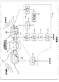
- FIG. 6 is a diagram showing an example of the configuration of a sound collection system (hereinafter referred to as Example 1) as an embodiment for improving the S / N using the noise canceling process as described above.
- Example 1 a sound collection system
- parts that are the same as the parts that have already been described are assigned the same reference numerals and description thereof is omitted.
- the sound collection system as the first embodiment includes a mounting unit 1, a mounting unit 2, and a signal processing unit 3.
- the mounting unit 1 should be mounted on one ear of the wearer H
- the mounting unit 2 should be mounted on the other ear of the wearer H.
- the mounting unit 2 is configured such that at least a part thereof can be inserted into the ear hole HB of the wearer H and can be mounted on the ear of the wearer H.
- the mounting part 2 is also formed with an ear hole insertion part 2A that can be inserted into the ear hole part HB of the wearer H, and the ear hole insertion part 2A is inserted into the ear hole part HB.
- the wearing unit 2 is put into a wearing state with respect to the ear part of the wearer H.
- the wearing portion 2 is also configured to form an internal space 2V connected to the ear canal HA of the wearer H in the wearing state to the wearer H, and the ear hole insertion portion 2A has a surface portion thereof. It is covered with an elastic material so that it can be in close contact with the ear canal HB when worn.
- a speaker 2S is disposed in the internal space 2V.
- the speaker 2S is provided for outputting a reception sound based on the reception signal. That is, as shown in the figure, the speaker 2S is driven based on the received signal amplified by the amplifier 17 provided in the signal processing unit 3, and thereby outputs a received sound corresponding to the received signal.
- the speaker S2 adopts a BA (balanced armature) type in consideration of the installation space.
- the mounting unit 1 is provided with an external microphone 1 ⁇ / b> C that is installed so that sound generated outside the housing of the mounting unit 1 can be directly collected.
- the mounting unit 1 is provided with a speaker 1S in the internal space 1V of the mounting unit 1.
- the MEMS microphone is used for the external microphone 1C as well as the internal microphone 1B.
- a BA type speaker is adopted as the speaker 1S in consideration of the installation space.
- the external microphone 1 ⁇ / b> C may be installed so as to be able to collect sound corresponding to noise canceling processing by the FF method (feed forward method) described later, and the sound collecting port is not necessarily provided in the housing of the mounting unit 1. There is no need to express it directly to the outside world.
- the signal processing unit 3 includes the microphone 17, the equalizer 11, the noise gate processing unit 12, the compressor 13, the microphone amplifier 14, and the NC filter 15 described with reference to FIG. (NC: noise canceling), an amplifier 16 is provided. Note that since the microphone amplifier 10, the equalizer 11, the noise gate processing unit 12, and the compressor 13 have already been described, redundant description is avoided.
- the collected sound signal from the external microphone 1 ⁇ / b> C provided in the mounting unit 1 is amplified by the microphone amplifier 14 and then input to the NC filter 15.
- the NC filter 15 generates a noise canceling signal by the FF method based on a sound collection signal from the external microphone 1 ⁇ / b> C input via the microphone amplifier 14.
- the NC filter 15 performs an equalization process corresponding to the FF method on the collected sound signal to generate a noise canceling signal for suppressing noise propagating in the internal space 1V of the mounting unit 1. Generate.
- the amplifier 16 amplifies the noise canceling signal obtained by the NC filter 15 and drives the speaker 1S in the mounting unit 1. As a result, a noise canceling sound based on the noise canceling signal is output from the speaker 1S. That is, as a result, the noise component propagating to the internal space 1V can be suppressed.
- the NC processing may be realized by using an analog filter circuit, or may be realized by digital signal processing including ADC by a method described in Reference Document 1 below. ⁇ Reference 1 ... JP 2008-193421 A
- the S / N of the utterance sound collection signal is secured by the (passive) sound insulation performance of the housing of the mounting portion 1 against environmental noise, and the internal space is obtained by NC processing.
- the internal space is obtained by NC processing.
- the utterance voice of the wearer H is picked up at the same level as when the NC process is not used together because the voice transmitted through the ear canal HA is transmitted to the base regardless of the NC process. Is.
- an embodiment including a signal processing unit 3 that realizes NC processing for realizing noise canceling of the internal space 1V as described above and various signal processing (equalizer 11 to compressor 13) for improving sound quality.
- a signal processing unit 3 that realizes NC processing for realizing noise canceling of the internal space 1V as described above and various signal processing (equalizer 11 to compressor 13) for improving sound quality.
- various signal processing (equalizer 11 to compressor 13) for improving sound quality.
- FIG. 7 is a diagram showing a configuration example of each of “integrated type” and “separated type”.
- the signal processing unit 3 is provided inside the housing of the mounting unit 1.
- S / N is improved by NC processing using the NC filter 15 for the external device 50 (for example, an information processing device such as a smartphone), and sound quality is improved by the equalizer 11 or the like.
- the collected sound signal by the illustrated internal microphone 1 is output as a transmission signal.
- the signal processing unit (the amplifier 17 in the case of FIG. 6) related to the channel on the mounting unit 2 side which is the channel on the opposite side to the mounting unit 1 is It is desirable to provide it. If the signal processing unit 3 shown in FIG. 6 is incorporated in the mounting unit 1 as it is, a separate wiring is required to transmit the amplified reception signal from the amplifier 17 from the mounting unit 1 side to the mounting unit 2 side. It is because it ends.
- the signal processing unit 3 is provided inside the external device 50.
- a sound collection signal transmission sound collection signal in the figure
- a sound collection signal in the figure, a sound collection signal for NC
- a noise canceling signal (NC signal in the figure) amplified by the amplifier 16 of the signal processing unit 3 is transmitted from the external device 50 to the mounting unit 1 (speaker 1S).
- the reception signal amplified by the amplifier 17 is transmitted from the external device 50 to the mounting unit 2 (speaker 2S).
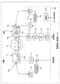
- [3-2. Example 2] 8 and 9 are explanatory diagrams of the configuration of the sound collection system as the second embodiment.
- the wearer H can listen to the received sound by providing the external microphone 2C and the NC filter 22 in the channel on the wearing unit 2 side (hereinafter also referred to as ch) to suppress noise in the internal space 2V.
- the control unit 20A in the drawing realizes switching between the call mode and the music listening mode.
- the signal processing unit 20 in the drawing in the second embodiment is configured by, for example, a DSP (Digital Signal Processor) or MPU (Micro Processing Unit), and the signal processing in the drawing is performed. It is assumed that each block shown in the unit 20 shows functions realized by these DSPs and MPUs in blocks.
- the case where the mounting portion 1 side is the Lch side and the mounting portion 2 side is the Rch side is illustrated.
- the mounting unit 2 is provided with an external microphone 2C for obtaining a sound pickup signal corresponding to noise canceling by the FF method, similarly to the external microphone 1C of the mounting unit 1 side.
- the signal processing unit 20 has functions similar to those of the respective units (the microphone amplifier 10 to the amplifier 17) included in the signal processing unit 3 of the first embodiment, the microphone amplifier 21, and the NC filter. 22 and a function as an adder 23 are added.
- the microphone amplifier 21 amplifies a sound collection signal from the external microphone 2C.
- the NC filter 22 performs equalization processing corresponding to the FF method similar to the previous NC filter 15 on the collected sound signal from the external microphone 2C amplified by the microphone amplifier 21, and thereby propagates in the internal space 2V.
- a noise canceling signal for suppressing noise is obtained.
- the adder 23 adds the noise canceling signal obtained by the NC filter 23 to the received signal, and gives the signal after the addition to the amplifier 17.
- the S / N improvement effect and sound quality improvement of the uttered sound collection signal are the same as in the first embodiment. An effect is obtained.
- the control unit 20A can switch the configuration of the functional unit of the signal processing unit 20 between the configuration shown in FIG. 8 and the configuration shown in FIG. 9 in response to the mode instruction signal for instructing the call mode / music listening mode. To control.
- Lch and Rch music signals are input to the signal processing unit 20.
- the function units the microphone amplifier 10 to the compressor 13 shown in FIG. 8 corresponding to the signal processing system for the sound collection signal by the internal microphone 1B are provided.
- a functional unit as an adding unit 24 for adding the Lch music signal to the noise canceling signal output from the NC filter 15 is formed.
- the addition signal of the Lch music signal and the noise canceling signal obtained by the adding unit 24 is amplified by the amplifier 16 and output from the speaker 1S.
- the configuration of the functional unit is the same as that in the call mode of FIG.
- the sound collection system as the second embodiment normally allows the wearer H to listen to the sound based on the Lch / Rch music signal in a silent state in which noise is suppressed. It has the same function as the sound reproduction system with NC function.
- each mounting portion (1, 2) of the sound collection system as the second embodiment is compared to the earphone portion of the channel on one side of the FF system-compatible earphone device.
- This can be realized only by adding the internal microphone 1B.
- the FF type earphone device compatible with the NC system originally has left and right speakers (1S, 2S) and an external microphone (1C, 2C) for noise pickup for NC, as Example 2.
- an internal microphone 1B may be added to one earphone part. Since the number of changes to the existing product can be reduced in this way, an increase in product cost can be effectively suppressed in realizing the system as the second embodiment.
- the second embodiment can adopt both “integrated” and “separated” configurations as shown in FIG. This also applies to each embodiment described below.
- the sound collection system according to the second embodiment can also be configured by hardware.
- the Lch side first includes the microphone amplifier 10 to the compressor 13 shown in FIG. 8, and the microphone amplifier 14, the NC filter 15, the amplifier 14, and the addition unit shown in FIG. 24 is provided.
- an Lch music signal is input to the adding unit 24 via a switch, and the control unit 20A turns off the switch in the call mode and supplies the Lch music signal to the adding unit 24.
- the switch is turned on so that the Lch music signal is supplied to the adding unit 24.
- the speech collection system may be configured so that a sound collection signal (transmission signal) is output via the microphone amplifier 10 to the compressor 13 only in correspondence with the call mode.
- the receiving unit or the Rch music signal may be input to the adding unit 23.
- FIG. 10 is a diagram illustrating a configuration of a sound collection system according to the third embodiment.
- FIG. 10 only the configuration of the mounting unit 1 and the signal processing system of the ch on the mounting unit 1 side is extracted and shown.
- Example 3 the configuration of the mounting unit 2 and the ch of the mounting unit 2 side are shown.
- the configuration of the signal processing system a configuration that allows the wearer H to listen to the received sound based on the received signal, such as the configuration shown in FIGS.
- the sound collection system in this case is provided with a signal processing unit 25 instead of the signal processing unit 3 in comparison with the sound collection system of the first embodiment shown in FIG.
- the signal processing unit 25 is different from the signal processing unit 3 in that an addition unit 24, an echo canceller 26, and an addition unit 27 are newly added.
- the adder 24 adds the received signal to the noise canceling signal output from the NC filter 15 and outputs the resultant signal to the amplifier 16 as in the adder 24 shown in FIG. As a result, a received sound based on the received signal is output together with the noise canceling sound from the speaker 1S in the mounting unit 1.
- the received sound (and noise canceling sound) output from the speaker 1S is emitted to the internal space 1V of the mounting unit 1, so that the received sound is collected by the internal microphone 1B. It will be sounded. That is, the internal microphone 1B in this case picks up the received voice together with the utterance sound of the wearer H, which may make it difficult for the other party to hear the utterance sound.
- the echo canceller 26 and the adder 27 are provided to subtract the component of the received sound collected by the internal microphone 1B via the internal space 1V from the collected sound signal by the internal microphone 1B. Yes.
- the echo canceller 26 transmits “speaker 1S ⁇ internal space 1V ⁇ internal microphone 1B” that is not actually subtracted from the collected sound signal but is actually added to the collected sound component of the uttered sound.
- Filter processing (equalization processing) using a transfer function that imitates the characteristics of the speaker 1S, the acoustic space characteristics of the internal space 1V, and the microphone characteristics of the internal microphone 1B for the received signal so that the received signal component is subtracted.
- the adder 27 adds the received signal subjected to the filter processing by the echo canceller 26 to the collected sound signal from the internal microphone 1 ⁇ / b> B input via the microphone amplifier 10, and sends the result to the noise gate processor 12. Output.
- the component of the received sound that is heard by the other party can be effectively suppressed, and as a result, the uttered sound can be heard more clearly by the other party.
- the echo canceller for sequentially updating the filter contents is provided.
- the above-described characteristics the characteristics of the speaker 1S, the acoustic space characteristics of the internal space 1V, and the microphone characteristics of the internal microphone 1B. It is good also as what provides the filter which performs the normal equalization process which considered ().
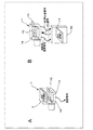
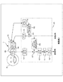
- FIG. 11 is a diagram illustrating a configuration of a sound collection system according to the fourth embodiment.
- the fourth embodiment employs an FB (feedback) method instead of the FF method as a noise canceling method.
- the external microphone 1C is omitted from the mounting unit 1 and the signal processing unit 25 is compared with the sound collection system of the third embodiment shown in FIG. Instead, a signal processing unit 30 is provided.
- the signal processing unit 30 omits the microphone amplifier 14 and the NC filter 15 used in the FF type NC processing, and further, the NC filter 31 and the equalizer 32 corresponding to the FB type. And are provided.
- the fourth embodiment is the same as the third embodiment in that the received signal is subtracted using the echo canceller 26 from the component reproduced by the speaker 1S.
- the FB method is a method of generating a noise canceling signal based on a result of collecting noise propagating to the internal space 1V of the mounting unit 1 (a space where sound is output from the speaker 1S).
- the internal microphone 1B is shared as a microphone that collects noise corresponding to the FB system.
- the collected sound signal from the internal microphone 1B is amplified by the microphone amplifier 10 and then supplied to the adder 27 and the NC filter 31 as shown in the figure.
- the NC filter 31 performs an equalization process corresponding to the FB method on the collected sound signal from the internal microphone 1B input via the microphone amplifier 10, thereby reducing noise propagating in the internal space 1V of the mounting unit 1.
- a noise canceling signal for suppression is generated.
- the noise canceling signal obtained by the NC filter 31 is added by the adder 24 with the received signal after being equalized by the equalizer 32 and output to the amplifier 16. Thereby, the noise canceling sound corresponding to the FB method is output from the speaker 1S, and as a result, noise in the internal space 1V can be suppressed.
- the sound based on the received signal is reproduced by the speaker 1S and then enters the internal microphone 1B (in this case, also used as a noise collecting microphone) and has an NC effect. Therefore, the sound quality changes from normal playback. For this reason, an equalizer 32 for correcting the sound quality in consideration of this influence is installed in advance for the received signal.
- the transmission signal S / S similar to that in the first to third embodiments is used. N improvement effect is obtained. Further, by adopting the FB method, there is an advantage that the external microphone 1C can be omitted.
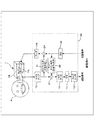
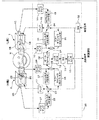
- FIG. 12 is a diagram illustrating a configuration of a sound collection system according to the fifth embodiment.
- so-called beam forming processing is performed on the speech signal collected by both the L and R channels to further improve the S / N of the speech collection signal.
- the so-called FF + FB method that simultaneously operates the FF method and the FB method as a noise canceling method, it is possible to further reduce noise in the internal space of the wearing portion, thereby reducing the utterance sound collection.
- Improve S / N in the fifth embodiment, similarly to the third and fourth embodiments, the reception sound is also output from the speaker 1S (and the speaker 2S).
- the sound collection system according to the fifth embodiment is compared with the sound collection system according to the second embodiment shown in FIG. 8, and the utterance sound collection via the external auditory canal HA and the noise by the FB method are also performed on the Rch side.
- An internal microphone 2B is provided in the internal space 2V of the mounting portion 2 so that the canceling process can be performed.
- a signal processing unit 35 is provided instead of the signal processing unit 20.
- the signal processing unit 35 is different from the signal processing unit 20 in the following points. First, for the configuration on the Lch side, which is the mounting unit 1 side, an adder 24, an NC filter 31, an echo canceller 26, and an adder 27 are added in order to support the FB method and the received sound output. . On the other hand, regarding the configuration on the Rch side, which is the mounting unit 2 side, a microphone amplifier 36 and an NC filter 37 are added to correspond to the FB method, and an echo canceller 38 and an adder 39 are added. In addition, as a configuration common to both channels, an equalizer 32 that performs equalization processing on the received signal and a beam forming processing unit 40 are added to support the FB system.
- the collected sound signal from the internal microphone 1B amplified by the microphone amplifier 10 is input to the NC filter 31 corresponding to the FB system, and the output of the NC filter 31 is supplied to the adding unit 24.
- the adder 24 adds the output of the NC filter 31, the output of the FF NC filter 15, and the received signal after the equalization processing by the equalizer 32 used in the FB method. The result is output to the amplifier 16.
- the sound collection signal from the internal microphone 2B amplified by the microphone amplifier 36 is input to the NC filter 37 corresponding to the FB system, and the output of the NC filter 37 is the addition unit 23.
- the adder 23 in this case adds the output of the NC filter 37, the output of the FF NC filter 22, and the received signal that has passed through the equalizer 32, and outputs the result to the amplifier 17.
- noise canceling processing by the FF + FB method is realized in both the Lch and Rch.
- Reference Document 2 Japanese Patent Application Laid-Open (1998), according to the FF + FB method, a wider noise and a greater noise reduction effect can be realized as compared with the case where the FF method or the FB method is operated alone. Can do. That is, according to the above configuration, it is possible to more effectively suppress noise in the internal spaces 1V and 2V, and as a result, it is possible to further improve the S / N of the uttered sound collection signal.
- the signal processing unit 35 is provided with an echo canceller 26 and an echo canceller 38 similar to those in the third and fourth embodiments, corresponding to the output of the received sound from the speakers 1S and 2S.
- the echo canceller 26 receives the reception signal that has passed through the equalizer 32, and performs echo cancellation processing similar to that described in the third embodiment.
- the output of the echo canceller 26 is added by the adder 27 with the sound pickup signal from the internal microphone 1B after being amplified by the microphone amplifier 10.
- the echo canceller 38 receives the reception signal that has passed through the equalizer 32, and performs echo cancellation processing similar to that described in the third embodiment.
- the output of the echo canceller 38 is added by the adder 39 to the sound pickup signal from the internal microphone 2B after being amplified by the microphone amplifier 36.
- a beam forming processing unit 40 In the signal processing unit 35, a beam forming processing unit 40 is provided.
- the beam forming processing unit 40 uses a sound collection signal (Lch side sound collection signal) obtained by the internal microphone 1B obtained from the addition unit 27 and a sound collection signal (Rch side sound collection signal) obtained by the internal microphone 2B obtained from the addition unit 39. Input and perform beamforming processing.
- the process of adding the Lch sound pickup signal and the Rch sound pickup signal can be most simply mentioned.
- the internal microphone 1B that performs speech collection on the Lch side and the internal microphone 2B that performs speech collection on the Rch side are approximately equidistant from the mouth (voice zone) of the wearer H that is the speech source. Therefore, the sound from the utterance source (via the external auditory canal HA) is efficiently extracted by adding the collected sound signals in the beamforming processing unit 40, and from other directions. Sound (noise component) can be suppressed. That is, further S / N improvement of the utterance sound pickup signal can be achieved.
- a sound component from the sound source direction is determined from the sound analysis result of the collected sound signal, and only the sound component from the sound source direction is determined from the determination result.
- An extraction method can be used.
- a process of determining a dominant component in the collected sound signal may be performed.
- noise reduction by, for example, the SS method (SS: Spectrum Subtraction) other than the above-described beam forming processing. It is good also as what performs a process.
- the noise reduction processing of the SS method is disclosed in Reference Document 3 below, for example.
- Reference 3 below also discloses a configuration in which noise canceling processing by the FF method or FB method and noise reduction processing by the SS method or the like are simultaneously operated. ⁇ Reference 3 ... JP 2010-11117 A
- the sound collection is performed in monaural.
- the equalizer 11, the noise gate processing unit 12, and the compressor 13 are provided independently on the Lch side and the Rch side, respectively.
- the speakers 1S and 2S are based on the BA type, but instead, speakers based on the dynamic type or the capacitor type can be used. Also, the system is not particularly limited with respect to the internal microphones 1B and 2B and the external microphones 1C and 2C.
- the present technology may be configured as follows. (1) At least a part thereof is configured to be insertable into the ear canal part, and a mounting part configured to form a substantially sealed internal space connected to the external auditory canal inside the ear hole part in a mounted state; An internal microphone that is arranged in the internal space of the mounting portion and that collects the uttered sound that is emitted by the wearer and propagates through the ear canal under the mounting state in the ear canal; An equalizing processing unit for performing high-frequency emphasizing type equalizing processing on the collected sound signal from the internal microphone; A speaker disposed in the internal space of the mounting portion; A noise canceling processing unit for outputting a noise canceling sound for reducing noise propagating to the internal space of the mounting unit based on a sound pickup signal from a microphone provided for the mounting unit; An ear hole mounting type sound pickup device provided.
- the noise canceling processing unit A noise canceling signal based on a feedforward method is generated based on a sound pickup signal from an external microphone arranged to pick up the external sound of the mounting portion, and the noise canceling sound based on the noise canceling signal is The ear hole-mounted sound collecting device according to (1), wherein the sound is output from a speaker.
- the noise canceling processing unit A noise canceling signal based on a feedback method is generated based on a sound pickup signal from a microphone arranged to pick up sound in the internal space of the mounting portion, and the noise canceling sound based on the noise canceling signal is generated.
- the ear hole-mounted sound collecting device according to (1) wherein the sound is output from the speaker.
- the noise canceling processing unit The ear canal-mounted sound collecting device according to (3), wherein a noise canceling signal by the feedback method is generated based on a sound collecting signal by the internal microphone.
- the noise canceling processing unit Generates a noise canceling signal by a feedforward method based on a sound collected by an external microphone arranged to pick up the external sound of the mounting part, and collects sound in the internal space of the mounting part
- the noise canceling signal based on the feedback method is generated based on the sound pickup signal from the microphone arranged so as to be output, and the noise canceling sound based on the two noise canceling signals is output from the speaker.
- the internal microphone and the speaker are respectively arranged as a first internal microphone and a first speaker in the internal space of the first mounting portion, respectively.
- the noise canceling processing unit The first noise canceling sound for reducing the noise propagating to the internal space of the first mounting portion is based on the sound collected signal from the microphone provided on the first mounting portion side.
- a second speaker is disposed in the internal space of the second mounting portion;
- the earpiece mounting type sound collecting device according to any one of (1) to (5), further including a second received sound output unit that outputs sound based on the received signal from the second speaker.
- a second noise canceling sound for reducing noise propagating to the internal space of the second mounting portion is generated based on a sound collected signal from a microphone provided on the second mounting portion side.
- the ear hole mounting type sound collecting apparatus according to (6), further including a second noise canceling processing unit that outputs the sound from two speakers.
- An ear hole-mounted sound collecting device according to any one of (1) to (8).
- a second internal microphone and a second speaker are arranged as the internal microphone and the speaker, respectively.
- the noise canceling processing unit The first noise canceling sound for reducing the noise propagating to the internal space of the first mounting portion is based on the sound collected signal from the microphone provided on the first mounting portion side. Propagating to the internal space of the second mounting portion based on a first noise canceling processing portion to be output from one speaker and a sound collected signal by a microphone provided on the second mounting portion side A second noise canceling processing unit for outputting a second noise canceling sound for reducing noise from the second speaker, and a sound pickup signal from the first internal microphone and the second noise canceling unit.
- a ear forming type sound collecting device comprising a beam forming processing unit for performing beam forming processing based on a sound collecting signal from an internal microphone. .
- the ear hole mounting type sound collecting device according to any one of (1) to (10), wherein the equalizing processing unit and the noise canceling processing unit are provided inside the mounting unit.
- the ear hole-mounted sound collection device according to any one of (1) to (11), further including a noise gate processing unit that performs noise gate processing on a sound collection signal from the internal microphone.
- the ear hole-mounted sound collecting device according to any one of (1) to (12), further including a compressor processing unit that performs a compressor process on a sound collected signal from the internal microphone.
- At least a part of the mounting part is configured to be insertable into the ear hole part, and the mounting part is configured so that a substantially sealed internal space connected to the ear canal is formed in the ear hole part in a mounted state.
- An equalizing processing unit for applying A noise canceling sound for reducing noise propagating to the internal space of the mounting portion is arranged in the internal space of the mounting portion based on a sound pickup signal from a microphone provided for the mounting portion.
- a signal processing apparatus comprising: a noise canceling processing unit that outputs from a speaker.
Landscapes
- Engineering & Computer Science (AREA)
- Physics & Mathematics (AREA)
- Acoustics & Sound (AREA)
- Multimedia (AREA)
- Signal Processing (AREA)
- Audiology, Speech & Language Pathology (AREA)
- Health & Medical Sciences (AREA)
- General Health & Medical Sciences (AREA)
- Computational Linguistics (AREA)
- Quality & Reliability (AREA)
- Human Computer Interaction (AREA)
- Soundproofing, Sound Blocking, And Sound Damping (AREA)
- Headphones And Earphones (AREA)
- Circuit For Audible Band Transducer (AREA)
- Details Of Audible-Bandwidth Transducers (AREA)
Priority Applications (3)
| Application Number | Priority Date | Filing Date | Title |
|---|---|---|---|
| EP12855706.3A EP2790417A4 (en) | 2011-12-08 | 2012-11-30 | AUDIO RECORDING DEVICE FOR MOUNTING THE OHLOCH, SIGNAL PROCESSING DEVICE AND METHOD FOR TAKING SOUND |
| CN201280059003.1A CN103959814B (zh) | 2011-12-08 | 2012-11-30 | 耳孔可佩戴式声音收集设备,信号处理设备和声音收集方法 |
| US14/360,959 US9361902B2 (en) | 2011-12-08 | 2012-11-30 | Earhole-wearable sound collection device, signal processing device, and sound collection method |
Applications Claiming Priority (2)
| Application Number | Priority Date | Filing Date | Title |
|---|---|---|---|
| JP2011-268781 | 2011-12-08 | ||
| JP2011268781A JP6069829B2 (ja) | 2011-12-08 | 2011-12-08 | 耳孔装着型収音装置、信号処理装置、収音方法 |
Publications (1)
| Publication Number | Publication Date |
|---|---|
| WO2013084811A1 true WO2013084811A1 (ja) | 2013-06-13 |
Family
ID=48574179
Family Applications (1)
| Application Number | Title | Priority Date | Filing Date |
|---|---|---|---|
| PCT/JP2012/081055 Ceased WO2013084811A1 (ja) | 2011-12-08 | 2012-11-30 | 耳孔装着型収音装置、信号処理装置、収音方法 |
Country Status (5)
| Country | Link |
|---|---|
| US (1) | US9361902B2 (enExample) |
| EP (1) | EP2790417A4 (enExample) |
| JP (1) | JP6069829B2 (enExample) |
| CN (1) | CN103959814B (enExample) |
| WO (1) | WO2013084811A1 (enExample) |
Cited By (1)
| Publication number | Priority date | Publication date | Assignee | Title |
|---|---|---|---|---|
| CN113228706A (zh) * | 2019-07-08 | 2021-08-06 | 松下知识产权经营株式会社 | 扬声器系统、声音处理装置、声音处理方法以及程序 |
Families Citing this family (19)
| Publication number | Priority date | Publication date | Assignee | Title |
|---|---|---|---|---|
| JP6019553B2 (ja) | 2011-08-31 | 2016-11-02 | ソニー株式会社 | イヤホン装置 |
| JP5919686B2 (ja) | 2011-08-31 | 2016-05-18 | ソニー株式会社 | 音響再生装置 |
| US10070211B2 (en) * | 2013-06-28 | 2018-09-04 | Kopin Corporation | Digital voice processing method and system for headset computer |
| US10659889B2 (en) * | 2013-11-08 | 2020-05-19 | Infineon Technologies Ag | Microphone package and method for generating a microphone signal |
| CN203982799U (zh) * | 2014-07-31 | 2014-12-03 | 张瑞博 | 一种隐密型录音播放设备的结构 |
| US9905216B2 (en) * | 2015-03-13 | 2018-02-27 | Bose Corporation | Voice sensing using multiple microphones |
| CN104952458B (zh) * | 2015-06-09 | 2019-05-14 | 广州广电运通金融电子股份有限公司 | 一种噪声抑制方法、装置及系统 |
| US9762991B2 (en) * | 2015-08-10 | 2017-09-12 | Cotron Corporation | Passive noise-cancellation of an in-ear headset module |
| TWI763727B (zh) * | 2016-10-24 | 2022-05-11 | 美商艾孚諾亞公司 | 使用多個麥克風的自動噪音消除 |
| KR102535726B1 (ko) | 2016-11-30 | 2023-05-24 | 삼성전자주식회사 | 이어폰 오장착 검출 방법, 이를 위한 전자 장치 및 저장 매체 |
| EP3422736B1 (en) * | 2017-06-30 | 2020-07-29 | GN Audio A/S | Pop noise reduction in headsets having multiple microphones |
| US10511915B2 (en) * | 2018-02-08 | 2019-12-17 | Facebook Technologies, Llc | Listening device for mitigating variations between environmental sounds and internal sounds caused by the listening device blocking an ear canal of a user |
| CN108429950A (zh) * | 2018-03-22 | 2018-08-21 | 恒玄科技(上海)有限公司 | 低功耗的高效降噪耳机及降噪系统 |
| JP6822693B2 (ja) * | 2019-03-27 | 2021-01-27 | 日本電気株式会社 | 音声出力装置、音声出力方法および音声出力プログラム |
| CN110164425A (zh) * | 2019-05-29 | 2019-08-23 | 北京声智科技有限公司 | 一种降噪方法、装置及可实现降噪的设备 |
| CN112055283A (zh) * | 2020-09-01 | 2020-12-08 | 苏州中科速衡电子有限公司 | 一种声电传感器主动降噪模组和一种声音监测仪 |
| US12256203B2 (en) | 2020-12-25 | 2025-03-18 | Panasonic Intellectual Property Management Co., Ltd. | Ear-worn device and reproduction method |
| CN113763945B (zh) * | 2020-12-29 | 2024-05-17 | 北京沃东天骏信息技术有限公司 | 一种语音唤醒方法、装置、设备及存储介质 |
| CN114697812B (zh) * | 2020-12-29 | 2023-06-20 | 华为技术有限公司 | 声音采集方法、电子设备及系统 |
Citations (7)
| Publication number | Priority date | Publication date | Assignee | Title |
|---|---|---|---|---|
| JPH0879873A (ja) * | 1994-09-08 | 1996-03-22 | Sony Corp | 通信端末 |
| JP2008116782A (ja) | 2006-11-07 | 2008-05-22 | Sony Corp | ノイズキャンセリングシステムおよびノイズキャンセル方法 |
| JP2008193421A (ja) | 2007-02-05 | 2008-08-21 | Sony Corp | 信号処理装置、信号処理方法 |
| JP2009141698A (ja) * | 2007-12-06 | 2009-06-25 | Rohm Co Ltd | ヘッドセット |
| JP4352932B2 (ja) | 2004-02-26 | 2009-10-28 | ソニー株式会社 | マイクロホン装置 |
| JP2010011117A (ja) | 2008-06-27 | 2010-01-14 | Sony Corp | ノイズ低減音声再生装置およびノイズ低減音声再生方法 |
| JP2010147982A (ja) * | 2008-12-22 | 2010-07-01 | Hosiden Corp | リモコン付きステレオイヤホンマイク |
Family Cites Families (12)
| Publication number | Priority date | Publication date | Assignee | Title |
|---|---|---|---|---|
| US7039195B1 (en) * | 2000-09-01 | 2006-05-02 | Nacre As | Ear terminal |
| US7773759B2 (en) * | 2006-08-10 | 2010-08-10 | Cambridge Silicon Radio, Ltd. | Dual microphone noise reduction for headset application |
| DE102007035366A1 (de) * | 2007-07-27 | 2009-01-29 | Bayer Materialscience Ag | Wässrige Polymerisat-Sekundärdispersionen zur Herstellung von Beschichtungen |
| JP2009141675A (ja) * | 2007-12-06 | 2009-06-25 | Rohm Co Ltd | ヘッドホンおよびヘッドホン用ケーブル |
| US20090147982A1 (en) | 2007-12-06 | 2009-06-11 | Rohm Co., Ltd. | Headphone set and headphone cable |
| CN101953176A (zh) * | 2008-02-20 | 2011-01-19 | 皇家飞利浦电子股份有限公司 | 音频设备及其操作方法 |
| JP4697267B2 (ja) * | 2008-07-01 | 2011-06-08 | ソニー株式会社 | ハウリング検出装置およびハウリング検出方法 |
| WO2010129241A1 (en) * | 2009-04-28 | 2010-11-11 | Bose Corporation | Dynamically configurable anr filter and signal processing topology |
| JP5499633B2 (ja) * | 2009-10-28 | 2014-05-21 | ソニー株式会社 | 再生装置、ヘッドホン及び再生方法 |
| JP5593852B2 (ja) * | 2010-06-01 | 2014-09-24 | ソニー株式会社 | 音声信号処理装置、音声信号処理方法 |
| JP2012023637A (ja) * | 2010-07-15 | 2012-02-02 | Audio Technica Corp | ノイズキャンセルヘッドホン |
| US10218327B2 (en) * | 2011-01-10 | 2019-02-26 | Zhinian Jing | Dynamic enhancement of audio (DAE) in headset systems |
-
2011
- 2011-12-08 JP JP2011268781A patent/JP6069829B2/ja not_active Expired - Fee Related
-
2012
- 2012-11-30 US US14/360,959 patent/US9361902B2/en not_active Expired - Fee Related
- 2012-11-30 EP EP12855706.3A patent/EP2790417A4/en not_active Withdrawn
- 2012-11-30 WO PCT/JP2012/081055 patent/WO2013084811A1/ja not_active Ceased
- 2012-11-30 CN CN201280059003.1A patent/CN103959814B/zh not_active Expired - Fee Related
Patent Citations (7)
| Publication number | Priority date | Publication date | Assignee | Title |
|---|---|---|---|---|
| JPH0879873A (ja) * | 1994-09-08 | 1996-03-22 | Sony Corp | 通信端末 |
| JP4352932B2 (ja) | 2004-02-26 | 2009-10-28 | ソニー株式会社 | マイクロホン装置 |
| JP2008116782A (ja) | 2006-11-07 | 2008-05-22 | Sony Corp | ノイズキャンセリングシステムおよびノイズキャンセル方法 |
| JP2008193421A (ja) | 2007-02-05 | 2008-08-21 | Sony Corp | 信号処理装置、信号処理方法 |
| JP2009141698A (ja) * | 2007-12-06 | 2009-06-25 | Rohm Co Ltd | ヘッドセット |
| JP2010011117A (ja) | 2008-06-27 | 2010-01-14 | Sony Corp | ノイズ低減音声再生装置およびノイズ低減音声再生方法 |
| JP2010147982A (ja) * | 2008-12-22 | 2010-07-01 | Hosiden Corp | リモコン付きステレオイヤホンマイク |
Non-Patent Citations (1)
| Title |
|---|
| See also references of EP2790417A4 * |
Cited By (1)
| Publication number | Priority date | Publication date | Assignee | Title |
|---|---|---|---|---|
| CN113228706A (zh) * | 2019-07-08 | 2021-08-06 | 松下知识产权经营株式会社 | 扬声器系统、声音处理装置、声音处理方法以及程序 |
Also Published As
| Publication number | Publication date |
|---|---|
| JP6069829B2 (ja) | 2017-02-01 |
| CN103959814A (zh) | 2014-07-30 |
| EP2790417A1 (en) | 2014-10-15 |
| US20140307884A1 (en) | 2014-10-16 |
| CN103959814B (zh) | 2017-05-03 |
| US9361902B2 (en) | 2016-06-07 |
| EP2790417A4 (en) | 2015-07-29 |
| JP2013121105A (ja) | 2013-06-17 |
Similar Documents
| Publication | Publication Date | Title |
|---|---|---|
| JP6069829B2 (ja) | 耳孔装着型収音装置、信号処理装置、収音方法 | |
| US12501208B2 (en) | Earhole-wearable sound collection device, signal processing device, and sound collection method | |
| US9955250B2 (en) | Low-latency multi-driver adaptive noise canceling (ANC) system for a personal audio device | |
| JP6017825B2 (ja) | 特に「ハンズフリー」電話システム向けの近接音声信号を雑音除去するための手段を有するマイクロホンとイヤホンの組合せ型のオーディオ・ヘッドセット | |
| JP4631939B2 (ja) | ノイズ低減音声再生装置およびノイズ低減音声再生方法 | |
| US8948409B2 (en) | Audio headset with active noise control of the non-adaptive type for listening to an audio music source and/or for “hands-free” telephony functions | |
| US9478212B1 (en) | Systems and methods for use of adaptive secondary path estimate to control equalization in an audio device | |
| JP6315046B2 (ja) | 耳孔装着型収音装置、信号処理装置、収音方法 | |
| JP2015204627A (ja) | 電気的ヒスを低減するanc能動雑音制御オーディオヘッドセット | |
| CN102026080B (zh) | 音频处理系统和自适应反馈抵消方法 | |
| JP6197930B2 (ja) | 耳孔装着型収音装置、信号処理装置、収音方法 | |
| CN113015052B (zh) | 低频噪声降低的方法和可穿戴电子设备及信号处理模块 |
Legal Events
| Date | Code | Title | Description |
|---|---|---|---|
| 121 | Ep: the epo has been informed by wipo that ep was designated in this application |
Ref document number: 12855706 Country of ref document: EP Kind code of ref document: A1 |
|
| WWE | Wipo information: entry into national phase |
Ref document number: 14360959 Country of ref document: US |
|
| NENP | Non-entry into the national phase |
Ref country code: DE |