WO2013084766A1 - 噛合チェーンユニット - Google Patents
噛合チェーンユニット Download PDFInfo
- Publication number
- WO2013084766A1 WO2013084766A1 PCT/JP2012/080723 JP2012080723W WO2013084766A1 WO 2013084766 A1 WO2013084766 A1 WO 2013084766A1 JP 2012080723 W JP2012080723 W JP 2012080723W WO 2013084766 A1 WO2013084766 A1 WO 2013084766A1
- Authority
- WO
- WIPO (PCT)
- Prior art keywords
- chain
- hook
- meshing
- tooth plate
- pair
- Prior art date
- Legal status (The legal status is an assumption and is not a legal conclusion. Google has not performed a legal analysis and makes no representation as to the accuracy of the status listed.)
- Ceased
Links
Images




Classifications
-
- B—PERFORMING OPERATIONS; TRANSPORTING
- B66—HOISTING; LIFTING; HAULING
- B66F—HOISTING, LIFTING, HAULING OR PUSHING, NOT OTHERWISE PROVIDED FOR, e.g. DEVICES WHICH APPLY A LIFTING OR PUSHING FORCE DIRECTLY TO THE SURFACE OF A LOAD
- B66F3/00—Devices, e.g. jacks, adapted for uninterrupted lifting of loads
- B66F3/02—Devices, e.g. jacks, adapted for uninterrupted lifting of loads with racks actuated by pinions
- B66F3/06—Devices, e.g. jacks, adapted for uninterrupted lifting of loads with racks actuated by pinions with racks comprising pivotable toothed sections or segments, e.g. arranged in pairs
-
- F—MECHANICAL ENGINEERING; LIGHTING; HEATING; WEAPONS; BLASTING
- F16—ENGINEERING ELEMENTS AND UNITS; GENERAL MEASURES FOR PRODUCING AND MAINTAINING EFFECTIVE FUNCTIONING OF MACHINES OR INSTALLATIONS; THERMAL INSULATION IN GENERAL
- F16G—BELTS, CABLES, OR ROPES, PREDOMINANTLY USED FOR DRIVING PURPOSES; CHAINS; FITTINGS PREDOMINANTLY USED THEREFOR
- F16G13/00—Chains
- F16G13/18—Chains having special overall characteristics
- F16G13/20—Chains having special overall characteristics stiff; Push-pull chains
Definitions
- the present invention is incorporated in a drive device that moves a driven body forward and backward with respect to an installation surface in manufacturing equipment in various manufacturing fields, transport equipment in the transportation field, nursing equipment in the medical and welfare field, stage equipment in the art field, and the like.
- the present invention relates to a meshing chain unit.
- a meshing chain incorporated in a drive device there is a chain in which a plurality of inner link units are arranged in parallel (for example, see Patent Document 1).
- the strength of the entire chain is changed by changing the number and size of the meshing chains that mesh with each other to form an integral rigid body.
- the buckling strength or chain strength of the meshing chain is increased by increasing the number of meshing chain rows or increasing the chain size, the number of parts of the meshing chain will increase.
- the number of chain assembly steps increases and the chain assembly accuracy decreases, and the driving force of the meshing chain is increased in accordance with the increase of the chain weight to increase the energy loss when the meshing chain is driven. there were.
- the drive motor is increased in size to increase the driving force of the meshing chain in accordance with the increase in the chain weight, the installation space for the drive motor is increased. Therefore, the drive device provided with the meshing chain is increased in size. As a result, there is a problem in that other parts installation space in the drive device is limited.
- the thrust of the entire meshing chain according to the contact stress between the bushing or roller provided between the internal teeth plates constituting the meshing chain and the drive sprocket is the number of meshing chain rows.
- the meshing chain is increased.
- two rows are connected and thrust exceeding the thrust necessary for driving the chain is applied to the meshing chain, which increases the number of parts of the meshing chain and increases the part cost.
- an intermediate tooth plate is press-fitted between the meshing chain rows to increase the chain strength.
- the driving force applied to the bushing or roller is increased without increasing the contact area between the bushing provided on the single-row meshing chain or the roller inserted into the bushing and the driving sprocket, and the chain thrust of the entire meshing chain is increased. If it is increased, the contact pressure between the sprocket teeth of the drive sprocket and the bushing or roller will increase, so that the bushing or roller will be easily worn and damaged, reducing the durability of the meshing chain and increasing the bushing. Or, there is a problem that the maintenance cost of the meshing chain is increased because the parts need to be replaced with the wear of the roller.
- the object of the present invention is to increase the chain manufacturing cost accompanying the increase in the number of parts, increase the chain maintenance cost, increase the number of chain assembly steps, and improve the chain assembly accuracy. Lowering, increasing energy loss when driving the meshing chain, and limiting the space for installing parts, twisting the meshing chain, disconnecting the connecting pin to the external tooth plate, disconnecting the bushing from the internal tooth plate, and connecting pin to the external tooth plate. It is an object of the present invention to provide a meshing chain that avoids the inclination of the chain and prevents the deterioration of the chain durability and the rattling of the outer tooth plate and the inner tooth plate.
- the meshing chain unit includes an inner link unit formed by press-fitting a pair of front and rear bushes to a pair of left and right hook-shaped inner teeth plates that are spaced apart from each other, and the inner link unit.
- a plurality of meshed chains connected in the longitudinal direction of the chain are opposed to each other by a pair of front and rear connecting pins that press-fit a pair of front and rear pin holes of the hook-shaped outer tooth plate to the hook-shaped outer tooth plate.
- a pair of arrangements, the chain-shaped stiffening in a state in which the pair of meshing chains are meshed with each other and the hook-shaped external tooth plates facing each other are integrated with each other in the chain stiffening direction.
- the invention according to claim 2 is the meshing chain unit according to claim 1, wherein at least one of the hook-shaped inner tooth plate, the hook-shaped outer tooth plate, and the connecting pin connects the pair of meshing chains to each other.
- the meshing chain unit according to claim 1 of the present invention includes an inner link unit formed by press-fitting a pair of front and rear bushes to a pair of left and right hook-shaped inner teeth plates that are spaced apart from each other, and an outer side of the inner link unit.
- a pair of meshing chains connected in the longitudinal direction of the chain by a pair of front and rear connecting pins that press-fit and fit the hook-shaped external tooth plate to the pair of front and rear pin holes of the hook-shaped external tooth plate.
- the pair of meshing chains are engaged with each other with the hook-shaped inner teeth plates facing each other and the hook-shaped outer teeth plates facing each other, and the chain-stiffening portion is integrated in the chain-stiffening direction.
- the hook-shaped inner tooth plates and the hook-shaped outer tooth plates are disengaged from each other and branched to each other to form a meshing chain. Not only it can perform a stiffening and branching behavior, it is possible to obtain the significant effect that corresponds to the specific configuration as follows.
- the meshing chain unit according to claim 1 is configured such that when the pair of meshing chains project the chain stiffening portion onto a virtual plane that is orthogonal to the chain stiffening direction and includes the pin axis of the connecting pin.
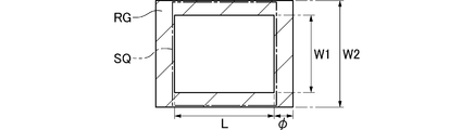
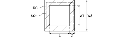
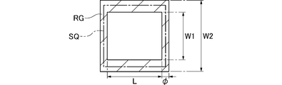
- the chain stiffening portion projection area of the chain stiffening portion is formed so that a square can be drawn on the chain stiffening portion projection region including the hook-shaped internal tooth plate projection region and the hook-shaped external tooth plate projection region.
- the mesh-direction supporting surface that secures the rigidity of the chain stiffening portion along the in-plane direction parallel to the respective plates of the tooth plate and the hook-shaped external tooth plate is constituted by the hook-shaped internal tooth plate and the hook-shaped external tooth plate.
- the chain stiffening part is isotropically secured along with the increase in the number of parts, the chain manufacturing cost increases, the chain maintenance cost increases, the number of chain assembly processes increases, the chain assembly accuracy decreases, the meshing chain drive This avoids an increase in energy loss and restrictions on the installation space of the parts, and avoids twisting of the meshing chain, disconnection of the connection pin with respect to the external tooth plate, disconnection of the bush with respect to the internal tooth plate, and inclination of the connection pin with respect to the external tooth plate. Moreover, it is possible to avoid deterioration of the chain durability and rattling of the external tooth plate and the internal tooth plate.
- the meshing chain unit according to claim 2 has at least one of the hook-shaped inner tooth plate, the hook-shaped outer tooth plate, and the connecting pin,
- the meshing operation of the pair of meshing chains is performed by elastically deforming in a state that there is no play between the parts constituting the pair of meshing chains.
- a pair of hook-shaped inner teeth plates and hook-shaped outer teeth plates are engaged with each other in a state in which an urging force generated due to elastic deformation of at least one of the hook-shaped inner tooth plate, the hook-shaped outer tooth plate and the connecting pin is applied.
- the meshing chain is configured as a single row.
- the rigidity of the chain stiffening part is increased to increase the chain manufacturing cost due to the increase in the number of parts, etc., increase the chain maintenance cost, increase the number of chain assembly processes, decrease the chain assembly accuracy, and reduce energy loss when driving the meshing chain. It avoids the increase in the space for installation and parts, and avoids twisting of the meshing chain, disconnection of the connecting pin to the external tooth plate, disconnection of the bush to the internal tooth plate, and inclination of the connecting pin to the external tooth plate, and durability of the chain And the backlash of the external tooth plate and the internal tooth plate can be further avoided.
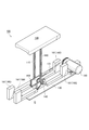
- FIG. 2 The perspective view of the meshing chain type advance / retreat operation device incorporating the meshing chain unit according to the present invention.
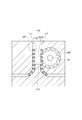
- the partial perspective view of the meshing chain type advance / retreat operation apparatus shown in FIG. FIG. 2 is a partially enlarged view of the meshing chain type advance / retreat operation device shown in FIG. 1.
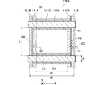
- Sectional drawing of the meshing chain which comprises the meshing chain unit which concerns on this invention.
- the meshing chain unit of the present invention includes an inner link unit formed by press-fitting a pair of front and rear bushes on a pair of left and right hook-shaped inner teeth plates that are spaced apart from each other, and a hook shape that is disposed outside the inner link unit.
- a pair of meshing chains that are connected in the longitudinal direction of the chain by a pair of front and rear connecting pins that press fit the outer tooth plate into a pair of front and rear pin holes of the hook-shaped outer tooth plate are arranged opposite to each other.
- the chain-stiffened part is formed in a state where the hook-shaped inner tooth plates facing each other and the hook-shaped outer tooth plates facing each other are meshed and integrated in the chain stiffening direction and hook-shaped.
- the inner tooth plates and the hook-like outer tooth plates are disengaged from each other and branched to each other, and a pair of meshing chains are connected to the chain rigid
- the chain rigidized portion is projected onto a virtual plane that is orthogonal to the forming direction and includes the pin axis of the connecting pin, the connecting pin projecting region, the hook-shaped internal tooth plate projecting region, and the hook-shaped external tooth plate projecting region of the chain stiffening portion
- the surface is parallel to the hook-shaped inner tooth plate and the hook-shaped outer tooth plate in a state where the meshing chain is formed in a single row by being formed so that a square can be drawn in the chain rigidized partial projection region consisting of Increase the chain manufacturing cost, increase chain maintenance cost, increase the number of chain assembly processes, increase the number of chain assembly processes, increase the number of parts by securing the rigidity of the chain stiffening portion isotropically along the inward and chain width directions Reduces accuracy, increases energy loss when driving the meshing chain, avoids restrictions on parts installation space, and
- the chain-stiffened partial projection region is a mouth shape that contributes to chain stiffening among the well-shaped cross-sectional region composed of the connecting pin projection region, the hook-shaped internal tooth plate projection region, and the hook-shaped external tooth plate projection region of the chain stiffening portion. Means a cross-sectional area.
- the “meshing direction support surface” and the “width direction support surface” in the meshing chain unit of the present invention are a virtual plane that is orthogonal to the chain stiffening direction and includes the pin axis of the connecting pin, A virtual plate cutting surface and a pin cutting surface formed by cutting the tooth plate and the connection pin are defined, and a connection pin projection region, a hook-like internal tooth plate projection region, and a hook-like external tooth plate projection region are formed, respectively.
- the meshing chain unit of the present invention may be driven by a driving sprocket provided at a rigid position where a pair of meshing chains are integrally meshed, or disposed in a branch region where the pair of meshing chains branch from each other.
- the meshing chain unit of the present invention may be driven by a driving sprocket that meshes with one of a pair of meshing chains that mesh with each other to be rigid, or is driven by two driving sprockets that mesh with the pair of meshing chains, respectively. May be.
- the interlocking chain type advance / retreat operation device equipped with the interlocking chain unit of the present invention does not move forward or backward regardless of whether the installation surface is a floor surface in a stationary installation form or a ceiling surface in a suspended installation form. There is no hindrance, and there is no hindrance to the advancing and retreating operation described above even if the wall surface is a cantilevered support.
- FIG. 1 is a perspective view of a meshing chain type advance / retreat operation device incorporating the meshing chain unit according to the present invention
- FIG. 2 is a partial perspective view of the meshing chain type advance / retreat operation device shown in FIG.
- FIG. 3 is a partially enlarged view of the meshing chain type advance / retreat operation device shown in FIG. 1
- FIG. 4A is an exploded perspective view of the meshing chain according to the present invention
- FIG. 4B is a diagram according to the present invention.
- Fig. 5 is a perspective view of the meshing chain unit
- Fig. 1 is a perspective view of a meshing chain type advance / retreat operation device incorporating the meshing chain unit according to the present invention
- FIG. 2 is a partial perspective view of the meshing chain type advance / retreat operation device shown in FIG.
- FIG. 3 is a partially enlarged view of the meshing chain type advance / retreat operation device shown in FIG. 1
- FIG. 4A is an exploded perspective view of the meshing chain according
- FIG. 5 is a cross-sectional view of the meshing chain constituting the meshing chain unit according to the present invention
- Fig. 6A is a diagram of a chain stiffening portion of the meshing chain unit according to the present invention.
- 6B is an enlarged cross-sectional view of the portion 6B shown in FIG. 6A
- FIG. 6C is a view showing the portion 6C shown in FIG. 6B
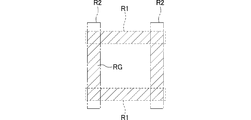
- FIG. 7 shows the chain stiffening partial region.
- the explanatory diagram of the drawn square 8 is an explanatory diagram of a square drawn in one modification of the chain stiffening partial region
- FIG. 9 is an explanatory diagram of a square drawn in another modification of the chain stiffening partial region.
- FIG. 10 is an explanatory diagram of a square drawn in another modification of the chain stiffening partial region.
- the solid line that defines the cross section of the member such as the external tooth plate and the dotted line and the alternate long and short dash line that define the region such as the plate projection region R2 are overlapped and coincide with each other.
- portions of the diagram that cannot be distinguished from each other are illustrated as being shifted from each other.
- the meshing chain type advance / retreat operation device 100 incorporating the meshing chain unit 110 according to the present embodiment is installed in a stationary state on an installation surface such as a work floor surface, and a heavy object or the like is installed.
- a driven body 120 such as a lifting table on which a driven object (not shown) is mounted is moved up and down in parallel with the installation surface G.
- the meshing chain type advance / retreat operation device 100 includes a base plate 130 installed on the installation surface G on which the driven body 120 moves up and down in parallel, and a parallel to the base plate 130.
- a motor is connected to a driving sprocket 140 that rotates forward and backward so that one of a pair of meshing chains 111, 111 described later can be moved forward and backward by rotating forward and backward around the installed rotating shaft 141, and a driven sprocket 153 that rotates the driving sprocket 140.
- a drive motor 150 that transmits power via the side sprocket 141 and the power transmission chain 151 and a chain that is disposed in the crotch region at the deflection position of the pair of meshing chains 111 and 111 and guides the pair of meshing chains 111 and 111 to each other
- a chain guide 180 for positioning and meshing the other meshing chain 111 with one meshing chain 111 and a peripheral region of the lowest lowered position of the driven body 120, that is, outside the area under the projection umbrella of the driven body 120
- a chain storage means 160 comprising a winding-type chain storage box 161 that winds and stores one of the pair of meshing chains 111 and 111 that are separated from each other and branched.
- a driven body 120 on which a driven object such as a workpiece is mounted is directly supported by a pair of meshing chains 111 and 111 to be raised and lowered.
- the pair of meshing chains 111, 111 described above are arranged in two sets on the left and right sides with respect to the driven body 120, and are in a so-called two-protruding state.
- the pair of meshing chains 111 and 111 respectively disposed on the left and right sides of the driven body 120 divides the total load including the mounted driven object into two parts to reduce the load. It is designed to move up and down in the state.
- the drive sprocket 140 is provided at a rigid position where the pair of meshing chains 111, 111 are integrally meshed with each other, and one bush of the pair of meshing chains 111, 111 is disposed.
- the pair of meshing chains 111 and 111 are driven by engaging with 111D. That is, the driving sprocket 140 and the meshing chain unit 110 exhibit a so-called pinion rack mechanism, and the meshing chain 111 is wound around the driving sprocket 140 at a deflection position where the driving sprocket 140 is deflected and driven from the chain branching direction to the chain meshing direction.
- the meshing chain unit 110 is formed by press-fitting a pair of front and rear bushes 111D to a pair of left and right hook-shaped internal teeth plates 111A that are spaced apart from each other.
- the link unit 111E and a hook-shaped external tooth plate 111B arranged outside the inner link unit 111E are inserted into a pair of front and rear pin holes of the hook-shaped external tooth plate 111B by a pair of front and rear connecting pins 111C to extend the length of the chain.
- a pair of meshing chains 111, 111 connected in a large number in the direction Y are arranged facing each other, and the pair of meshing chains 111, 111 are hook-shaped external teeth facing each other with the hook-shaped internal tooth plates 111A facing each other.
- the plates 111B are engaged with each other and integrated in the chain stiffening direction D1.
- the stiffening and branching operations of the pair of meshing chains 111 and 111 are formed by forming the rigid portion 110G and engaging the hook-like inner tooth plates 111A and the hook-like outer tooth plates 111B with each other and branching each other. Is supposed to do.
- the meshing chain unit 110 when the pair of meshing chains 111 and 111 project the chain stiffening portion 110G onto a virtual plane S that is orthogonal to the chain stiffening direction D1 and includes the pin axis of the connecting pin 111C.
- a square SQ is formed in the chain rigidized partial projection region RG made of R2.
- the hook-shaped inner tooth plate is provided with the meshing direction support surface S2 that ensures the rigidity of the chain stiffening portion 110G along the in-plane directions parallel to the hook-shaped inner tooth plate 111A and the hook-shaped outer tooth plate 111B.
- the chain is rigidly isotropic along the in-plane direction and the chain width direction X parallel to the hook-like inner tooth plate 111A and the hook-like outer tooth plate 111B.
- the rigidity of the modified portion 110G is secured and the chain manufacturing cost increases due to the increase in the number of parts, the chain maintenance cost increases, the number of chain assembly processes increases, the chain assembly accuracy decreases, the energy loss at the time of driving the meshing chain increases, and It avoids restrictions on the parts installation space and avoids twisting of the meshing chain 111, disconnection of the connection pin 111C from the external tooth plate 111B, disconnection of the bush 111D from the internal tooth plate 111A, and inclination of the connection pin 111C relative to the external tooth plate 111B.
- the durability of the chain and the external tooth plate It is adapted to avoid the backlash of the 11B and the internal tooth plate 111A. As shown in FIGS.
- the chain-stiffened partial projection region RG has an inner width W ⁇ b> 1 between the inner tooth plates 111 ⁇ / b> A facing each other along the chain width direction X, and along the chain width direction X. And a pair of couplings facing each other along the plate surfaces of the inner tooth plate 111A and the outer tooth plate 111B. Since the square SQ is defined based on the pin-to-pin distance L of the pins 111C and 111C, the square SQ has an inner width W1 between the inner tooth plates 111A, an outer width W2 between the outer tooth plates 111B, and a pin diameter of the connecting pin 111C. The size is appropriately changed according to ⁇ and the inter-pin distance L.
- the hook-shaped inner tooth plate 111A, the hook-shaped outer tooth plate 111B, and the connecting pin 111C meshes the pair of meshing chains 111 and 111 with each other.
- it is elastically deformed so that play between the parts constituting the pair of meshing chains 111, 111 is eliminated.
- the hook is engaged with the biasing force generated by the elastic deformation of at least one of the hook-shaped inner tooth plate 111A, the hook-shaped outer tooth plate 111B, and the connecting pin 111C during the meshing operation of the pair of mesh chains 111, 111.
- the inner teeth plates 111A and the hook outer teeth plates 111B are engaged with each other, and the pair of engagement chains 111, 111 are integrally rigidized to form a chain rigidity portion 110G. Therefore, in the state where the meshing chain 111 is configured in a single row, the rigidity of the chain stiffening portion 110G is increased to increase the chain manufacturing cost due to the increase in the number of parts, the chain maintenance cost, the number of chain assembly processes, the chain assembly A decrease in accuracy, an increase in energy loss when driving the meshing chain, and a restriction on the space for installing the parts are avoided, and the meshing chain 111 is twisted, the connecting pin 111C is disconnected from the external tooth plate 111B, and the bush 111D is disconnected from the internal tooth plate 111A. In addition, the inclination of the connecting pin 111C with respect to the external tooth plate 111B is avoided, and the deterioration of the chain durability and the backlash of the external tooth plate 111B and the internal tooth plate 111A are further avoided.
- the pair of meshing chains 111, 111 are orthogonal to the chain stiffness direction D1 and the chain rigidized portion is in a virtual plane S including the pin axis of the connecting pin 111C.
- a square SQ can be drawn in the chain rigidized partial projection region RG including the connecting pin projection region R1, the hook-shaped internal tooth plate projection region R2, and the hook-shaped external tooth plate projection region R3 of the chain rigidized portion 110G.
- the hook-shaped inner tooth plate 111A and the hook-shaped outer tooth plate 111B are parallel to the respective plates and along the chain width direction X.
- the chain stiffening part 110G rigidity is ensured to increase the number of parts. Increase in chain manufacturing cost, increase in chain maintenance cost, increase in the number of chain assembly processes, decrease in chain assembly accuracy, increase in energy loss during driving of the meshing chain, and restriction of space for installing parts and twisting of the meshing chain 111 Further, it is possible to avoid the disconnection of the connection pin 111C with respect to the external tooth plate 111B, the disconnection of the bush 111D with respect to the internal tooth plate 111A, and the inclination of the connection pin 111C with respect to the external tooth plate 111B. The effect is enormous, for example, rattling of the tooth plate 111A can be avoided.
Landscapes
- Engineering & Computer Science (AREA)
- Mechanical Engineering (AREA)
- General Engineering & Computer Science (AREA)
- Life Sciences & Earth Sciences (AREA)
- Geology (AREA)
- Structural Engineering (AREA)
- Transmission Devices (AREA)
Abstract
チェーン製造及び維持コストの増大、組立工程数の増加、組み立て精度の低下、駆動時のエネルギー損失の増大及び部品設置スペースの制限、噛合チェーンの捩れ、外歯プレートに対する連結ピンの抜け、内歯プレートに対するブシュの抜け、及び外歯プレートに対する連結ピンの傾斜を回避し、しかもチェーン耐久性の低下や外歯プレート等のガタツキを回避する噛合チェーンユニットを提供すること。 一対の噛合チェーン(111、111)が、チェーン剛直化部分(110G)の連結ピン投影領域(R1)、フック状内歯プレート投影領域及びフック状外歯プレート投影領域すなわち相隣接したフック状内歯プレート(111A)及びフック状外歯プレート(111B)で形成されるプレート投影領域(R2)からなるチェーン剛直化部分投影領域(RG)に正方形(SQ)を描けるように形成されている噛合チェーンユニット(110)。
Description
本発明は、各種製造分野の製造設備、運輸分野の移送設備、医療福祉分野の介護設備、芸術分野の舞台設備などに用いて被駆動体を設置面に対して進退動させる駆動装置に組み込まれる噛合チェーンユニットに関するものである。
従来、駆動装置に組み込まれる噛合チェーンとしては、複数の内リンクユニットを並列に配置したもの(例えば、特許文献1参照。)がある。
また、相互に噛み合って一体の剛体となる噛合チェーンの列数やサイズを変更してチェーン全体の強度を変更する場合もある。
また、相互に噛み合って一体の剛体となる噛合チェーンの列数やサイズを変更してチェーン全体の強度を変更する場合もある。
しかしながら、噛合チェーンの列数を増やしたりチェーンサイズを増大させたりして噛合チェーンの座屈強度やチェーン強度を高めた場合、噛合チェーンの部品点数を増大させてしまうため、チェーン製造コストの増大、チェーン組立工程数の増加、及びチェーン組み立て精度の低下を生じさせてしまうとともにチェーン重量の増大に応じて噛合チェーンの駆動力を増大させて噛合チェーン駆動時にエネルギー損失を増大させてしまうという問題点があった。
また、チェーン重量の増大に応じて噛合チェーンの駆動力を増大させるために駆動モータを大型化した場合、駆動モータの設置スペースを増大させてしまうため、噛合チェーンを設けた駆動装置を大型化させて駆動装置内の他の部品設置スペースに制限を生じさせてしまうという問題点があった。
また、チェーン重量の増大に応じて噛合チェーンの駆動力を増大させるために駆動モータを大型化した場合、駆動モータの設置スペースを増大させてしまうため、噛合チェーンを設けた駆動装置を大型化させて駆動装置内の他の部品設置スペースに制限を生じさせてしまうという問題点があった。
また、噛合チェーンを複数列設けた場合、列数の増大に伴って内歯プレート同士及び外歯プレート同士の噛み合い箇所を増加させてしまうため、複数の噛み合い箇所で内歯プレート同士及び外歯プレート同士に作用する力に偏りを生じさせて噛合チェーンに捩れを生じさせてしまうという問題点があった。
また、チェーン長手方向に相前後して設けられた連結ピンのピン間隔を広げて噛合チェーンの座屈強度を高めようとした場合、噛合チェーンの捩れに応じてブシュや外歯プレートに対する連結ピンの圧入部に力を作用させてしまうため、ブシュや連結ピンを内歯プレート及び外歯プレートに対して傾斜させてしまうとともに連結ピンが外歯プレートとの圧入嵌合部から抜けたり、ブシュが内歯プレートとの圧入嵌合部から抜けたりしてしまうという不具合を生じさせてしまうという問題点があった。
また、噛合チェーンを複数列を設けた状態で相互に隣り合うチェーン列同士の間に中間歯プレートを配置した場合、プレートの公差やチェーンの組み立て誤差に起因して外歯プレートより中間歯プレートのサイズが長くなる場合があるため、中間歯プレートを支点としてその両側の外歯プレート及び内歯プレートにガタツキを生じさせてしまうという問題点があった。
また、チェーン長手方向に相前後して設けられた連結ピンのピン間隔を広げて噛合チェーンの座屈強度を高めようとした場合、噛合チェーンの捩れに応じてブシュや外歯プレートに対する連結ピンの圧入部に力を作用させてしまうため、ブシュや連結ピンを内歯プレート及び外歯プレートに対して傾斜させてしまうとともに連結ピンが外歯プレートとの圧入嵌合部から抜けたり、ブシュが内歯プレートとの圧入嵌合部から抜けたりしてしまうという不具合を生じさせてしまうという問題点があった。
また、噛合チェーンを複数列を設けた状態で相互に隣り合うチェーン列同士の間に中間歯プレートを配置した場合、プレートの公差やチェーンの組み立て誤差に起因して外歯プレートより中間歯プレートのサイズが長くなる場合があるため、中間歯プレートを支点としてその両側の外歯プレート及び内歯プレートにガタツキを生じさせてしまうという問題点があった。
また、噛合チェーンを並列に複数連結した場合、噛合チェーンを構成する内歯プレート間に設けられたブシュまたはローラと駆動用スプロケットとの接触応力に応じた噛合チェーン全体の推力を噛合チェーンの列数に応じて2倍、3倍と整数倍で増大させてしまうため、例えば、一列の噛合チェーンに作用する推力の1.5倍の推力をチェーン全体で必要とする場合であっても噛合チェーンを2列連結してチェーン駆動に必要な推力以上の推力を噛合チェーンに作用させることになり、噛合チェーンの部品点数を余分に増加させて部品コストを増大させてしまうという問題点があった。
また、噛合チェーンの列数をチェーン幅方向に増やして噛合チェーンの座屈を回避した場合、噛合チェーンの列間に中間歯プレートを圧入してチェーン強度を高めることになるため、上述した必要以上の推力を噛合チェーンに作用させてしまう場合と同様に、噛合チェーンの部品点数を増加させてチェーンの部品コストを増大させてしまうという問題点があった。
また、単列の噛合チェーンに設けられたブシュまたはブシュに挿入されたローラと駆動用スプロケットとの接触面積を増大させないでブシュまたはローラに作用させる駆動力を増大させて噛合チェーン全体のチェーン推力を増大させた場合、駆動用スプロケットのスプロケット歯とブシュまたローラとの噛合部分の面圧が増大するため、ブシュまたはローラを容易に摩耗および破損させて噛合チェーンの耐久性を低下させてしまうとともにブシュまたはローラの摩耗に伴って部品を交換する必要を生じさせて噛合チェーンの維持コストを増大させてしまうという問題点があった。
また、噛合チェーンの列数をチェーン幅方向に増やして噛合チェーンの座屈を回避した場合、噛合チェーンの列間に中間歯プレートを圧入してチェーン強度を高めることになるため、上述した必要以上の推力を噛合チェーンに作用させてしまう場合と同様に、噛合チェーンの部品点数を増加させてチェーンの部品コストを増大させてしまうという問題点があった。
また、単列の噛合チェーンに設けられたブシュまたはブシュに挿入されたローラと駆動用スプロケットとの接触面積を増大させないでブシュまたはローラに作用させる駆動力を増大させて噛合チェーン全体のチェーン推力を増大させた場合、駆動用スプロケットのスプロケット歯とブシュまたローラとの噛合部分の面圧が増大するため、ブシュまたはローラを容易に摩耗および破損させて噛合チェーンの耐久性を低下させてしまうとともにブシュまたはローラの摩耗に伴って部品を交換する必要を生じさせて噛合チェーンの維持コストを増大させてしまうという問題点があった。
そこで、本発明が解決しようとする技術的課題、すなわち、本発明の目的は、部品点数増加等に伴うチェーン製造コストの増大、チェーン維持コストの増大、チェーン組立工程数の増加、チェーン組み立て精度の低下、噛合チェーン駆動時のエネルギー損失の増大及び部品設置スペースの制限を回避するとともに噛合チェーンの捩れ、外歯プレートに対する連結ピンの抜け、内歯プレートに対するブシュの抜け、及び外歯プレートに対する連結ピンの傾斜を回避し、しかもチェーン耐久性の低下や外歯プレート及び内歯プレートのガタツキを回避する噛合チェーンを提供することである。
まず、本請求項1に係る発明の噛合チェーンユニットは、相互に離間配置される左右一対のフック状内歯プレートに前後一対のブシュを圧入嵌合してなる内リンクユニットと該内リンクユニットの外側に配置されるフック状外歯プレートとを該フック状外歯プレートの前後一対のピン孔に圧入嵌合する前後一対の連結ピンによりチェーン長手方向に多数連結した噛合チェーンが相互に対向して一対配置され、該一対の噛合チェーンが相互に対向するフック状内歯プレート同士と相互に対向するフック状外歯プレート同士とをそれぞれ噛み合わせてチェーン剛直化方向に一体化した状態でチェーン剛直化部分を形成するとともにフック状内歯プレート同士とフック状外歯プレート同士とをそれぞれ噛み外して相互に分岐し、前記一対の噛合チェーンが、前記チェーン剛直化方向に直交するとともに前記連結ピンのピン軸を含む仮想平面に前記チェーン剛直化部分を投影した際に前記チェーン剛直化部分の連結ピン投影領域、フック状内歯プレート投影領域及びフック状外歯プレート投影領域からなるチェーン剛直化部分投影領域に正方形を描けるように形成されていることにより、前述した課題を解決したものである。
そして、本請求項2に係る発明は、請求項1に係る噛合チェーンユニットにおいて、前記フック状内歯プレート、前記フック状外歯プレート及び前記連結ピンの少なくとも一つが、前記一対の噛合チェーンを相互に噛み合わせてチェーン剛直化部分を形成する際に前記一対の噛合チェーンを構成する部品間の遊びを無くした状態に弾性変形することにより、前述した課題をさらに解決したものである。
本発明の請求項1に係る噛合チェーンユニットは、相互に離間配置される左右一対のフック状内歯プレートに前後一対のブシュを圧入嵌合してなる内リンクユニットと該内リンクユニットの外側に配置されるフック状外歯プレートとを該フック状外歯プレートの前後一対のピン孔に圧入嵌合する前後一対の連結ピンによりチェーン長手方向に多数連結した噛合チェーンが相互に対向して一対配置され、該一対の噛合チェーンが相互に対向するフック状内歯プレート同士と相互に対向するフック状外歯プレート同士とをそれぞれ噛み合わせてチェーン剛直化方向に一体化した状態でチェーン剛直化部分を形成するとともにフック状内歯プレート同士とフック状外歯プレート同士とをそれぞれ噛み外して相互に分岐することにより、噛合チェーンの剛直化および分岐動作を行うことができるばかりでなく、以下のような特有の構成に対応した格別の効果を奏することができる。
すなわち、本請求項1に係る噛合チェーンユニットは、前記一対の噛合チェーンが、前記チェーン剛直化方向に直交するとともに前記連結ピンのピン軸を含む仮想平面に前記チェーン剛直化部分を投影した際に前記チェーン剛直化部分の連結ピン投影領域、フック状内歯プレート投影領域及びフック状外歯プレート投影領域からなるチェーン剛直化部分投影領域に正方形を描けるように形成されていることにより、フック状内歯プレート及びフック状外歯プレートのそれぞれのプレートに平行な面内方向に沿ってチェーン剛直化部分の剛性を確保する噛合方向支持面をフック状内歯プレート及びフック状外歯プレートで構成するとともに左右一対のフック状内歯プレートの対向方向であるチェーン幅方向に沿ってチェーン剛直化部分の剛性を確保する幅方向支持面を連結ピンで構成するため、噛合チェーンを単列で構成した状態でフック状内歯プレート及びフック状外歯プレートのそれぞれのプレートに平行な面内方向及びチェーン幅方向に沿って等方的にチェーン剛直化部分の剛性を確保して部品点数増加等に伴うチェーン製造コストの増大、チェーン維持コストの増大、チェーン組立工程数の増加、チェーン組み立て精度の低下、噛合チェーン駆動時のエネルギー損失の増大及び部品設置スペースの制限を回避するとともに噛合チェーンの捩れ、外歯プレートに対する連結ピンの抜け、内歯プレートに対するブシュの抜け、及び外歯プレートに対する連結ピンの傾斜を回避し、しかもチェーン耐久性の低下や外歯プレート及び内歯プレートのガタツキを回避することができる。
そして、本請求項2に係る噛合チェーンユニットは、請求項1に係る噛合チェーンユニットが奏する効果に加えて、前記フック状内歯プレート、前記フック状外歯プレート及び前記連結ピンの少なくとも一つが、前記一対の噛合チェーンを相互に噛み合わせてチェーン剛直化部分を形成する際に前記一対の噛合チェーンを構成する部品間の遊びを無くした状態に弾性変形することにより、一対の噛合チェーンの噛み合い動作時にフック状内歯プレート、フック状外歯プレート及び連結ピンの少なくとも一つの弾性変形に伴って生じる付勢力を作用させた状態でフック状内歯プレート同士及びフック状外歯プレート同士を噛み合せて一対の噛合チェーンを一体に剛直化させてチェーン剛直化部分を形成するため、噛合チェーンを単列で構成した状態でチェーン剛直化部分の剛性を高めて部品点数増加等に伴うチェーン製造コストの増大、チェーン維持コストの増大、チェーン組立工程数の増加、チェーン組み立て精度の低下、噛合チェーン駆動時のエネルギー損失の増大及び部品設置スペースの制限を回避するとともに噛合チェーンの捩れ、外歯プレートに対する連結ピンの抜け、内歯プレートに対するブシュの抜け、及び外歯プレートに対する連結ピンの傾斜を回避し、しかもチェーン耐久性の低下や外歯プレート及び内歯プレートのガタツキをより一層回避することができる。
本発明の噛合チェーンユニットは、相互に離間配置される左右一対のフック状内歯プレートに前後一対のブシュを圧入嵌合してなる内リンクユニットとこの内リンクユニットの外側に配置されるフック状外歯プレートとをこのフック状外歯プレートの前後一対のピン孔に圧入嵌合する前後一対の連結ピンによりチェーン長手方向に多数連結した噛合チェーンが相互に対向して一対配置され、この一対の噛合チェーンが相互に対向するフック状内歯プレート同士と相互に対向するフック状外歯プレート同士とをそれぞれ噛み合わせてチェーン剛直化方向に一体化した状態でチェーン剛直化部分を形成するとともにフック状内歯プレート同士とフック状外歯プレート同士とをそれぞれ噛み外して相互に分岐し、一対の噛合チェーンが、チェーン剛直化方向に直交するとともに連結ピンのピン軸を含む仮想平面にチェーン剛直化部分を投影した際にチェーン剛直化部分の連結ピン投影領域、フック状内歯プレート投影領域及びフック状外歯プレート投影領域からなるチェーン剛直化部分投影領域に正方形を描けるように形成されていることにより、噛合チェーンを単列で構成した状態でフック状内歯プレート及びフック状外歯プレートのそれぞれのプレートに平行な面内方向及びチェーン幅方向に沿って等方的にチェーン剛直化部分の剛性を確保して部品点数増加等に伴うチェーン製造コストの増大、チェーン維持コストの増大、チェーン組立工程数の増加、チェーン組み立て精度の低下、噛合チェーン駆動時のエネルギー損失の増大及び部品設置スペースの制限を回避するとともに噛合チェーンの捩れ、外歯プレートに対する連結ピンの抜け、内歯プレートに対するブシュの抜け、及び外歯プレートに対する連結ピンの傾斜を回避し、しかもチェーン耐久性の低下や外歯プレート及び内歯プレートのガタツキを回避するものであれば、その具体的な実施の態様は、如何なるものであっても何ら構わない。
また、チェーン剛直化部分投影領域は、チェーン剛直化部分の連結ピン投影領域、フック状内歯プレート投影領域及びフック状外歯プレート投影領域からなる井形の断面領域のうちチェーン剛直化に寄与する口形の断面領域を意味する。
また、本発明の噛合チェーンユニットにおける「噛合方向支持面」及び「幅方向支持面」は、チェーン剛直化方向に直交するとともに連結ピンのピン軸を含む仮想平面でフック状内プレート、フック状外歯プレート及び連結ピンを切って形成される仮想的なプレート切断面及びピン切断面を意味するとともにそれぞれ連結ピン投影領域とフック状内歯プレート投影領域及びフック状外歯プレート投影領域とを形成する。
また、本発明の噛合チェーンユニットは、一対の噛合チェーンを一体に噛み合せた剛直位置に設けられた駆動用スプロケットによって駆動されてもよいし、一対の噛合チェーンが相互に分岐する分岐領域に配置された駆動用スプロケットによって駆動されてもよい。
また、本発明の噛合チェーンユニットは、相互に噛み合って剛直化する一対の噛合チェーンの一方に噛み合う駆動用スプロケットによって駆動されてもよいし、一対の噛合チェーンにそれぞれ噛み合う2つの駆動用スプロケットによって駆動されてもよい。
また、本発明の噛合チェーンユニットを搭載した噛合チェーン式進退作動装置は、設置面が据え置き設置形態となる床面であっても、吊り下げ設置形態となる天井面であっても進退動作に何ら支障はなく、さらには、片持ち支持形態となる垂直壁面であっても前述した進退動作に何ら支障はない。
また、チェーン剛直化部分投影領域は、チェーン剛直化部分の連結ピン投影領域、フック状内歯プレート投影領域及びフック状外歯プレート投影領域からなる井形の断面領域のうちチェーン剛直化に寄与する口形の断面領域を意味する。
また、本発明の噛合チェーンユニットにおける「噛合方向支持面」及び「幅方向支持面」は、チェーン剛直化方向に直交するとともに連結ピンのピン軸を含む仮想平面でフック状内プレート、フック状外歯プレート及び連結ピンを切って形成される仮想的なプレート切断面及びピン切断面を意味するとともにそれぞれ連結ピン投影領域とフック状内歯プレート投影領域及びフック状外歯プレート投影領域とを形成する。
また、本発明の噛合チェーンユニットは、一対の噛合チェーンを一体に噛み合せた剛直位置に設けられた駆動用スプロケットによって駆動されてもよいし、一対の噛合チェーンが相互に分岐する分岐領域に配置された駆動用スプロケットによって駆動されてもよい。
また、本発明の噛合チェーンユニットは、相互に噛み合って剛直化する一対の噛合チェーンの一方に噛み合う駆動用スプロケットによって駆動されてもよいし、一対の噛合チェーンにそれぞれ噛み合う2つの駆動用スプロケットによって駆動されてもよい。
また、本発明の噛合チェーンユニットを搭載した噛合チェーン式進退作動装置は、設置面が据え置き設置形態となる床面であっても、吊り下げ設置形態となる天井面であっても進退動作に何ら支障はなく、さらには、片持ち支持形態となる垂直壁面であっても前述した進退動作に何ら支障はない。
以下、本発明の一実施例である噛合チェーンユニット110を図1乃至図10に基づいて説明する。
ここで、図1は、本発明に係る噛合チェーンユニットを組み込んだ噛合チェーン式進退作動装置の斜視図であり、図2は、図1に示した噛合チェーン式進退作動装置の一部斜視図であり、図3は、図1に示した噛合チェーン式進退作動装置の一部拡大図であり、図4Aは、本発明に係る噛合チェーンの分解斜視図であり、図4Bは、本発明に係る噛合チェーンユニットの斜視図であり、図5は、本発明に係る噛合チェーンユニットを構成する噛合チェーンの断面図であり、図6Aは、本発明に係る噛合チェーンユニットのチェーン剛直化部分の図であり、図6Bは、図6Aに示す符号6Bの箇所を拡大した断面図であり、図6Cは、図6Bに示す符号6Cの箇所を示す図であり、図7は、チェーン剛直化部分領域に描かれた正方形の説明図であり、図8は、チェーン剛直化部分領域の一変形例に描かれた正方形の説明図であり、図9は、チェーン剛直化部分領域の他の変形例に描かれた正方形の説明図であり、図10は、チェーン剛直化部分領域の他の変形例に描かれた正方形の説明図である。
なお、図6A乃至図6C中に示した外歯プレート等の部材の断面を規定する実線とプレート投影領域R2等の領域を規定する点線や一点鎖線とのうち相互に重なって一致し且つそのまま重ねて図示すると線同士の区別をできない線図部分は、説明の便宜上、線同士を区別するために相互にずらして図示している。
ここで、図1は、本発明に係る噛合チェーンユニットを組み込んだ噛合チェーン式進退作動装置の斜視図であり、図2は、図1に示した噛合チェーン式進退作動装置の一部斜視図であり、図3は、図1に示した噛合チェーン式進退作動装置の一部拡大図であり、図4Aは、本発明に係る噛合チェーンの分解斜視図であり、図4Bは、本発明に係る噛合チェーンユニットの斜視図であり、図5は、本発明に係る噛合チェーンユニットを構成する噛合チェーンの断面図であり、図6Aは、本発明に係る噛合チェーンユニットのチェーン剛直化部分の図であり、図6Bは、図6Aに示す符号6Bの箇所を拡大した断面図であり、図6Cは、図6Bに示す符号6Cの箇所を示す図であり、図7は、チェーン剛直化部分領域に描かれた正方形の説明図であり、図8は、チェーン剛直化部分領域の一変形例に描かれた正方形の説明図であり、図9は、チェーン剛直化部分領域の他の変形例に描かれた正方形の説明図であり、図10は、チェーン剛直化部分領域の他の変形例に描かれた正方形の説明図である。
なお、図6A乃至図6C中に示した外歯プレート等の部材の断面を規定する実線とプレート投影領域R2等の領域を規定する点線や一点鎖線とのうち相互に重なって一致し且つそのまま重ねて図示すると線同士の区別をできない線図部分は、説明の便宜上、線同士を区別するために相互にずらして図示している。
まず、図1に示すように、本実施例に係る噛合チェーンユニット110を組み込んだ噛合チェーン式進退作動装置100は、作業床面等の設置面に据え置き状態で設置されて、重量物などの被駆動物(図示しない)を搭載する昇降テーブルなどの被駆動体120を設置面Gに対して平行に昇降させるものである。
そして、噛合チェーン式進退作動装置100は、図1および図2に示すように、前述した被駆動体120が平行に昇降する設置面Gに据え付けたベースプレート130と、このベースプレート130に対して平行に設置された回転軸141を中心に正逆回転して後述する一対の噛合チェーン111、111の一方を進退自在に駆動する駆動用スプロケット140と、駆動用スプロケット140を回転させる従動側スプロケット153にモータ側スプロケット141および動力伝達チェーン151を介して動力を伝達する駆動モータ150と、一対の噛合チェーン111、111の偏向位置の股間領域に配置されて一対の噛合チェーン111、111を相互に誘導するチェーン誘導プレート170と、駆動用スプロケット140により駆動する一方の噛合チェーン111に他方の噛合チェーン111を位置決め噛み合わせて従動させるチェーンガイド180と、被駆動体120の最下降位置の周辺域、すなわち、被駆動体120の投影傘下の領域外に離間配置されているとともに、相互に噛み外れて分岐した一対の噛合チェーン111、111の一方を巻き取って収納する巻き取り型のチェーン収納ボックス161からなるチェーン収納手段160とを基本的な装置構成として備え、ワークなどの被駆動物を搭載した被駆動体120を一対の噛合チェーン111、111で直接的に支持して昇降させるようになっている。
前述した一対の噛合チェーン111、111は、被駆動体120に対して左右2組配置され、所謂、2本突き状態になっている。
これにより、被駆動物が被駆動体120上に偏在した状態で搭載されている場合や被駆動体120の最上昇位置近傍において被駆動体120の幅方向に生じがちな横揺れの虞れがある場合であっても、被駆動体120の左右両側にそれぞれ配置された一対の噛合チェーン111、111が、搭載された被駆動物を含めた全荷重を二分してその負荷を分担軽減した自立状態で昇降するようになっている。
これにより、被駆動物が被駆動体120上に偏在した状態で搭載されている場合や被駆動体120の最上昇位置近傍において被駆動体120の幅方向に生じがちな横揺れの虞れがある場合であっても、被駆動体120の左右両側にそれぞれ配置された一対の噛合チェーン111、111が、搭載された被駆動物を含めた全荷重を二分してその負荷を分担軽減した自立状態で昇降するようになっている。
また、図2および図3に示すように、駆動用スプロケット140は、一対の噛合チェーン111、111を一体に噛み合わせた剛直位置に設けられているとともに一対の噛合チェーン111、111の一方のブシュ111Dに係合して一対の噛合チェーン111、111を駆動する。
すなわち、駆動用スプロケット140および噛合チェーンユニット110が、所謂、ピニオンラック機構を呈することにより、チェーン分岐方向からチェーン噛合方向へ偏向駆動される偏向位置で噛合チェーン111を駆動用スプロケット140に巻き掛けた場合に駆動用スプロケット140と噛合チェーン111との間で生じる周知のコーダルアクション(多角形運動)に起因した脈動(上下動)が回避されるため、チェーン収納手段160に対する噛合チェーン111の出没動作を安定させることができる。
すなわち、駆動用スプロケット140および噛合チェーンユニット110が、所謂、ピニオンラック機構を呈することにより、チェーン分岐方向からチェーン噛合方向へ偏向駆動される偏向位置で噛合チェーン111を駆動用スプロケット140に巻き掛けた場合に駆動用スプロケット140と噛合チェーン111との間で生じる周知のコーダルアクション(多角形運動)に起因した脈動(上下動)が回避されるため、チェーン収納手段160に対する噛合チェーン111の出没動作を安定させることができる。
次に、本実施例に係る噛合チェーンユニット110の詳細な構成を図4Aおよび図4Bに基づいて説明する。
図4Aおよび図4Bに示すように、本実施例に係る噛合チェーンユニット110は、相互に離間配置される左右一対のフック状内歯プレート111Aに前後一対のブシュ111Dを圧入嵌合してなる内リンクユニット111Eと該内リンクユニット111Eの外側に配置されるフック状外歯プレート111Bとをこのフック状外歯プレート111Bの前後一対のピン孔に圧入嵌合する前後一対の連結ピン111Cによりチェーン長手方向Yに多数連結した噛合チェーン111、111が相互に対向して一対配置され、これら一対の噛合チェーン111、111が相互に対向するフック状内歯プレート111A同士と相互に対向するフック状外歯プレート111B同士とをそれぞれ噛み合わせてチェーン剛直化方向D1に一体化した状態でチェーン剛直化部分110Gを形成するとともにフック状内歯プレート111A同士とフック状外歯プレート111B同士とをそれぞれ噛み外して相互に分岐することにより、一対の噛合チェーン111、111の剛直化および分岐動作を行うようになっている。
図4Aおよび図4Bに示すように、本実施例に係る噛合チェーンユニット110は、相互に離間配置される左右一対のフック状内歯プレート111Aに前後一対のブシュ111Dを圧入嵌合してなる内リンクユニット111Eと該内リンクユニット111Eの外側に配置されるフック状外歯プレート111Bとをこのフック状外歯プレート111Bの前後一対のピン孔に圧入嵌合する前後一対の連結ピン111Cによりチェーン長手方向Yに多数連結した噛合チェーン111、111が相互に対向して一対配置され、これら一対の噛合チェーン111、111が相互に対向するフック状内歯プレート111A同士と相互に対向するフック状外歯プレート111B同士とをそれぞれ噛み合わせてチェーン剛直化方向D1に一体化した状態でチェーン剛直化部分110Gを形成するとともにフック状内歯プレート111A同士とフック状外歯プレート111B同士とをそれぞれ噛み外して相互に分岐することにより、一対の噛合チェーン111、111の剛直化および分岐動作を行うようになっている。
次に、前述した本実施例に係る噛合チェーンユニット110が最も特徴とする具体的な形態について、図4A乃至図10に基づいて詳しく説明する。
本実施例に係る噛合チェーンユニット110は、一対の噛合チェーン111、111が、チェーン剛直化方向D1に直交するとともに連結ピン111Cのピン軸を含む仮想平面Sにチェーン剛直化部分110Gを投影した際にチェーン剛直化部分110Gの連結ピン投影領域R1、フック状内歯プレート投影領域及びフック状外歯プレート投影領域すなわち相隣接したフック状内歯プレート及びフック状外歯プレートで形成されるプレート投影領域R2からなるチェーン剛直化部分投影領域RGに正方形SQを描けるように形成されている。これにより、フック状内歯プレート111A及びフック状外歯プレート111Bのそれぞれのプレートに平行な面内方向に沿ってチェーン剛直化部分110Gの剛性を確保する噛合方向支持面S2をフック状内歯プレート111A及びフック状外歯プレート111Bで構成するとともに左右一対のフック状内歯プレート111A,111Aの対向方向であるチェーン幅方向Xに沿ってチェーン剛直化部分110Gの剛性を確保する幅方向支持面S1を連結ピン111Cで構成する。そのため、噛合チェーン111を単列で構成した状態でフック状内歯プレート111A及びフック状外歯プレート111Bのそれぞれのプレートに平行な面内方向及びチェーン幅方向Xに沿って等方的にチェーン剛直化部分110Gの剛性を確保して部品点数増加等に伴うチェーン製造コストの増大、チェーン維持コストの増大、チェーン組立工程数の増加、チェーン組み立て精度の低下、噛合チェーン駆動時のエネルギー損失の増大及び部品設置スペースの制限を回避するとともに噛合チェーン111の捩れ、外歯プレート111Bに対する連結ピン111Cの抜け、内歯プレート111Aに対するブシュ111Dの抜け、及び外歯プレート111Bに対する連結ピン111Cの傾斜を回避し、しかもチェーン耐久性の低下や外歯プレート111B及び内歯プレート111Aのガタツキを回避するようになっている。
なお、図6A乃至図10に示すように、チェーン剛直化部分投影領域RGは、チェーン幅方向Xに沿って相互に対向する内歯プレート111A同士間の内幅W1と、チェーン幅方向Xに沿って相互に対向する外歯プレート111B同士間の外幅W2と、連結ピン111Cのピン径φと、内歯プレート111A及び外歯プレート111Bのそれぞれのプレート面に沿って相互に対向する一対の連結ピン111C、111Cのピン間距離Lとに基づいて規定されるため、正方形SQは、内歯プレート111A同士間の内幅W1と外歯プレート111B同士間の外幅W2と連結ピン111Cのピン径φとピン間距離Lとに応じてそのサイズを適宜変更されることになる。
本実施例に係る噛合チェーンユニット110は、一対の噛合チェーン111、111が、チェーン剛直化方向D1に直交するとともに連結ピン111Cのピン軸を含む仮想平面Sにチェーン剛直化部分110Gを投影した際にチェーン剛直化部分110Gの連結ピン投影領域R1、フック状内歯プレート投影領域及びフック状外歯プレート投影領域すなわち相隣接したフック状内歯プレート及びフック状外歯プレートで形成されるプレート投影領域R2からなるチェーン剛直化部分投影領域RGに正方形SQを描けるように形成されている。これにより、フック状内歯プレート111A及びフック状外歯プレート111Bのそれぞれのプレートに平行な面内方向に沿ってチェーン剛直化部分110Gの剛性を確保する噛合方向支持面S2をフック状内歯プレート111A及びフック状外歯プレート111Bで構成するとともに左右一対のフック状内歯プレート111A,111Aの対向方向であるチェーン幅方向Xに沿ってチェーン剛直化部分110Gの剛性を確保する幅方向支持面S1を連結ピン111Cで構成する。そのため、噛合チェーン111を単列で構成した状態でフック状内歯プレート111A及びフック状外歯プレート111Bのそれぞれのプレートに平行な面内方向及びチェーン幅方向Xに沿って等方的にチェーン剛直化部分110Gの剛性を確保して部品点数増加等に伴うチェーン製造コストの増大、チェーン維持コストの増大、チェーン組立工程数の増加、チェーン組み立て精度の低下、噛合チェーン駆動時のエネルギー損失の増大及び部品設置スペースの制限を回避するとともに噛合チェーン111の捩れ、外歯プレート111Bに対する連結ピン111Cの抜け、内歯プレート111Aに対するブシュ111Dの抜け、及び外歯プレート111Bに対する連結ピン111Cの傾斜を回避し、しかもチェーン耐久性の低下や外歯プレート111B及び内歯プレート111Aのガタツキを回避するようになっている。
なお、図6A乃至図10に示すように、チェーン剛直化部分投影領域RGは、チェーン幅方向Xに沿って相互に対向する内歯プレート111A同士間の内幅W1と、チェーン幅方向Xに沿って相互に対向する外歯プレート111B同士間の外幅W2と、連結ピン111Cのピン径φと、内歯プレート111A及び外歯プレート111Bのそれぞれのプレート面に沿って相互に対向する一対の連結ピン111C、111Cのピン間距離Lとに基づいて規定されるため、正方形SQは、内歯プレート111A同士間の内幅W1と外歯プレート111B同士間の外幅W2と連結ピン111Cのピン径φとピン間距離Lとに応じてそのサイズを適宜変更されることになる。
そして、本実施例に係る噛合チェーンユニット110は、フック状内歯プレート111A、フック状外歯プレート111B及び連結ピン111Cの少なくとも一つが、一対の噛合チェーン111、111を相互に噛み合わせてチェーン剛直化部分110Gを形成する際に一対の噛合チェーン111、111を構成する部品間の遊びを無くした状態に弾性変形する。これにより、一対の噛合チェーン111、111の噛み合い動作時にフック状内歯プレート111A、フック状外歯プレート111B及び連結ピン111Cの少なくとも一つの弾性変形に伴って生じる付勢力を作用させた状態でフック状内歯プレート111A同士及びフック状外歯プレート111B同士を噛み合せて一対の噛合チェーン111、111を一体に剛直化させてチェーン剛直化部分110Gを形成する。そのため、噛合チェーン111を単列で構成した状態でチェーン剛直化部分110Gの剛性を高めて部品点数増加等に伴うチェーン製造コストの増大、チェーン維持コストの増大、チェーン組立工程数の増加、チェーン組み立て精度の低下、噛合チェーン駆動時のエネルギー損失の増大及び部品設置スペースの制限を回避するとともに噛合チェーン111の捩れ、外歯プレート111Bに対する連結ピン111Cの抜け、内歯プレート111Aに対するブシュ111Dの抜け、及び外歯プレート111Bに対する連結ピン111Cの傾斜を回避し、しかもチェーン耐久性の低下や外歯プレート111B及び内歯プレート111Aのガタツキをより一層回避するようになっている。
このようにして得られた本発明の噛合チェーンユニット110では、一対の噛合チェーン111、111が、チェーン剛直化方向D1に直交するとともに連結ピン111Cのピン軸を含む仮想平面Sにチェーン剛直化部分110Gを投影した際にチェーン剛直化部分110Gの連結ピン投影領域R1、フック状内歯プレート投影領域R2及びフック状外歯プレート投影領域R3からなるチェーン剛直化部分投影領域RGに正方形SQを描けるように形成されていることにより、噛合チェーン111を単列で構成した状態でフック状内歯プレート111A及びフック状外歯プレート111Bのそれぞれのプレートに平行な面内方向及びチェーン幅方向Xに沿って等方的にチェーン剛直化部分110Gの剛性を確保して部品点数増加等に伴うチェーン製造コストの増大、チェーン維持コストの増大、チェーン組立工程数の増加、チェーン組み立て精度の低下、噛合チェーン駆動時のエネルギー損失の増大及び部品設置スペースの制限を回避するとともに噛合チェーン111の捩れ、外歯プレート111Bに対する連結ピン111Cの抜け、内歯プレート111Aに対するブシュ111Dの抜け、及び外歯プレート111Bに対する連結ピン111Cの傾斜を回避し、しかもチェーン耐久性の低下や外歯プレート111B及び内歯プレート111Aのガタツキを回避することができるなど、その効果は甚大である。
100 ・・・ 噛合チェーン式進退作動装置
110 ・・・ 噛合チェーンユニット
111 ・・・ 噛合チェーン
111A ・・・ フック状内歯プレート
111B ・・・ フック状外歯プレート
111C ・・・ 連結ピン
111D ・・・ ブシュ
111E ・・・ 内リンクユニット
120 ・・・ 被駆動体
130 ・・・ ベースプレート
140 ・・・ 駆動用スプロケット
141 ・・・ 駆動軸
150 ・・・ 駆動モータ
151 ・・・ 動力伝達チェーン
152 ・・・ 従動側スプロケット
160 ・・・ チェーン収納手段
161 ・・・ チェーン収納ボックス
170 ・・・ チェーン誘導プレート
180 ・・・ チェーンガイド
D1 ・・・ チェーン剛直化方向
G ・・・ 設置面
L ・・・ 連結ピンのピン間距離
W1 ・・・ 内歯プレートの内幅
W2 ・・・ 外歯プレートの外幅
S ・・・ 仮想平面
S1 ・・・ 幅方向支持面
S2 ・・・ 噛合方向支持面
RG ・・・ チェーン剛直化部分投影領域
R1 ・・・ チェーン剛直化部分の連結ピン投影領域
R2 ・・・ チェーン剛直化部分のうち相隣接したフック状内歯プレート及びフック状外歯プレートにより形成されるプレート投影領域
SQ ・・・ チェーン剛直化部分投影領域に描画可能な正方形
X ・・・ チェーン幅方向
Y ・・・ チェーン長手方向
φ ・・・ 連結ピンのピン径
110 ・・・ 噛合チェーンユニット
111 ・・・ 噛合チェーン
111A ・・・ フック状内歯プレート
111B ・・・ フック状外歯プレート
111C ・・・ 連結ピン
111D ・・・ ブシュ
111E ・・・ 内リンクユニット
120 ・・・ 被駆動体
130 ・・・ ベースプレート
140 ・・・ 駆動用スプロケット
141 ・・・ 駆動軸
150 ・・・ 駆動モータ
151 ・・・ 動力伝達チェーン
152 ・・・ 従動側スプロケット
160 ・・・ チェーン収納手段
161 ・・・ チェーン収納ボックス
170 ・・・ チェーン誘導プレート
180 ・・・ チェーンガイド
D1 ・・・ チェーン剛直化方向
G ・・・ 設置面
L ・・・ 連結ピンのピン間距離
W1 ・・・ 内歯プレートの内幅
W2 ・・・ 外歯プレートの外幅
S ・・・ 仮想平面
S1 ・・・ 幅方向支持面
S2 ・・・ 噛合方向支持面
RG ・・・ チェーン剛直化部分投影領域
R1 ・・・ チェーン剛直化部分の連結ピン投影領域
R2 ・・・ チェーン剛直化部分のうち相隣接したフック状内歯プレート及びフック状外歯プレートにより形成されるプレート投影領域
SQ ・・・ チェーン剛直化部分投影領域に描画可能な正方形
X ・・・ チェーン幅方向
Y ・・・ チェーン長手方向
φ ・・・ 連結ピンのピン径
Claims (2)
- 相互に離間配置される左右一対のフック状内歯プレートに前後一対のブシュを圧入嵌合してなる内リンクユニットと該内リンクユニットの外側に配置されるフック状外歯プレートとを該フック状外歯プレートの前後一対のピン孔に圧入嵌合する前後一対の連結ピンによりチェーン長手方向に多数連結した噛合チェーンが相互に対向して一対配置され、該一対の噛合チェーンが相互に対向するフック状内歯プレート同士と相互に対向するフック状外歯プレート同士とをそれぞれ噛み合わせてチェーン剛直化方向に一体化した状態でチェーン剛直化部分を形成するとともにフック状内歯プレート同士とフック状外歯プレート同士とをそれぞれ噛み外して相互に分岐する噛合チェーンユニットであって、
前記一対の噛合チェーンが、前記チェーン剛直化方向に直交するとともに前記連結ピンのピン軸を含む仮想平面に前記チェーン剛直化部分を投影した際に前記チェーン剛直化部分の連結ピン投影領域、フック状内歯プレート投影領域及びフック状外歯プレート投影領域からなるチェーン剛直化部分投影領域に正方形を描けるように形成されていることを特徴とする噛合チェーンユニット。 - 前記フック状内歯プレート、前記フック状外歯プレート及び前記連結ピンの少なくとも一つが、前記一対の噛合チェーンを相互に噛み合わせてチェーン剛直化部分を形成する際に前記一対の噛合チェーンを構成する部品間の遊びを無くした状態に弾性変形することを特徴とする請求項1に記載の噛合チェーンユニット。
Applications Claiming Priority (2)
| Application Number | Priority Date | Filing Date | Title |
|---|---|---|---|
| JP2011270372A JP5822703B2 (ja) | 2011-12-09 | 2011-12-09 | 噛合チェーンユニット |
| JP2011-270372 | 2011-12-09 |
Publications (1)
| Publication Number | Publication Date |
|---|---|
| WO2013084766A1 true WO2013084766A1 (ja) | 2013-06-13 |
Family
ID=48574136
Family Applications (1)
| Application Number | Title | Priority Date | Filing Date |
|---|---|---|---|
| PCT/JP2012/080723 Ceased WO2013084766A1 (ja) | 2011-12-09 | 2012-11-28 | 噛合チェーンユニット |
Country Status (2)
| Country | Link |
|---|---|
| JP (1) | JP5822703B2 (ja) |
| WO (1) | WO2013084766A1 (ja) |
Cited By (1)
| Publication number | Priority date | Publication date | Assignee | Title |
|---|---|---|---|---|
| EP2674385A4 (en) * | 2011-02-10 | 2014-08-27 | Tsubakimoto Chain Co | APPARATUS WITH AN INCLING CHAIN FOR OPERATION WITH FORWARD AND REVERSE MOTION |
Citations (2)
| Publication number | Priority date | Publication date | Assignee | Title |
|---|---|---|---|---|
| JP2008256202A (ja) * | 2007-03-13 | 2008-10-23 | Moritoshi Kondou | 伸縮装置 |
| JP2009113872A (ja) * | 2007-11-01 | 2009-05-28 | Tsubakimoto Chain Co | 昇降駆動用噛合チェーン |
Family Cites Families (1)
| Publication number | Priority date | Publication date | Assignee | Title |
|---|---|---|---|---|
| JP4662500B2 (ja) * | 2008-09-09 | 2011-03-30 | 株式会社椿本チエイン | 噛合チェーン式駆動装置 |
-
2011
- 2011-12-09 JP JP2011270372A patent/JP5822703B2/ja active Active
-
2012
- 2012-11-28 WO PCT/JP2012/080723 patent/WO2013084766A1/ja not_active Ceased
Patent Citations (2)
| Publication number | Priority date | Publication date | Assignee | Title |
|---|---|---|---|---|
| JP2008256202A (ja) * | 2007-03-13 | 2008-10-23 | Moritoshi Kondou | 伸縮装置 |
| JP2009113872A (ja) * | 2007-11-01 | 2009-05-28 | Tsubakimoto Chain Co | 昇降駆動用噛合チェーン |
Cited By (2)
| Publication number | Priority date | Publication date | Assignee | Title |
|---|---|---|---|---|
| EP2674385A4 (en) * | 2011-02-10 | 2014-08-27 | Tsubakimoto Chain Co | APPARATUS WITH AN INCLING CHAIN FOR OPERATION WITH FORWARD AND REVERSE MOTION |
| US8967005B2 (en) | 2011-02-10 | 2015-03-03 | Tsubakimoto Chain Co. | Engagement chain type device for forward and backward movement operation |
Also Published As
| Publication number | Publication date |
|---|---|
| JP5822703B2 (ja) | 2015-11-24 |
| JP2013122271A (ja) | 2013-06-20 |
Similar Documents
| Publication | Publication Date | Title |
|---|---|---|
| EP2320109B1 (en) | Engagement chain | |
| JP5340670B2 (ja) | 昇降駆動用噛合多列チェーン | |
| JP4875216B1 (ja) | 噛合チェーンユニット | |
| US8776491B2 (en) | Lifting engagement chain unit | |
| EP2674385B1 (en) | Engagement chain type device for forward and backward movement operation | |
| JP4662504B2 (ja) | 昇降駆動用噛合チェーン | |
| JP4509165B2 (ja) | 昇降駆動用噛合多列チェーン | |
| JP4662499B2 (ja) | 噛合チェーン | |
| JP2012225439A (ja) | 噛合チェーンユニット | |
| JP2009113872A (ja) | 昇降駆動用噛合チェーン | |
| WO2011004817A1 (ja) | 高剛性噛合チェーンユニット | |
| JP5822703B2 (ja) | 噛合チェーンユニット | |
| JP2011144874A (ja) | 噛合チェーン式進退作動装置 | |
| JP2011137514A (ja) | 噛合チェーン式進退作動装置 | |
| JP5901377B2 (ja) | 噛合チェーンユニット | |
| JP4681022B2 (ja) | 昇降駆動用噛合チェーン | |
| JP5046899B2 (ja) | 昇降駆動用噛合チェーン | |
| JP2010078120A (ja) | 昇降駆動用噛合チェーン | |
| JP2011137513A (ja) | 振動低減型噛合チェーン | |
| WO2012046491A1 (ja) | 噛合チェーン |
Legal Events
| Date | Code | Title | Description |
|---|---|---|---|
| 121 | Ep: the epo has been informed by wipo that ep was designated in this application |
Ref document number: 12854826 Country of ref document: EP Kind code of ref document: A1 |
|
| NENP | Non-entry into the national phase |
Ref country code: DE |
|
| 122 | Ep: pct application non-entry in european phase |
Ref document number: 12854826 Country of ref document: EP Kind code of ref document: A1 |