WO2013080975A1 - Impact resistant member - Google Patents
Impact resistant member Download PDFInfo
- Publication number
- WO2013080975A1 WO2013080975A1 PCT/JP2012/080633 JP2012080633W WO2013080975A1 WO 2013080975 A1 WO2013080975 A1 WO 2013080975A1 JP 2012080633 W JP2012080633 W JP 2012080633W WO 2013080975 A1 WO2013080975 A1 WO 2013080975A1
- Authority
- WO
- WIPO (PCT)
- Prior art keywords
- resistant member
- impact
- carbon fiber
- thermoplastic resin
- section
- Prior art date
Links
Images


Classifications
-
- F—MECHANICAL ENGINEERING; LIGHTING; HEATING; WEAPONS; BLASTING
- F16—ENGINEERING ELEMENTS AND UNITS; GENERAL MEASURES FOR PRODUCING AND MAINTAINING EFFECTIVE FUNCTIONING OF MACHINES OR INSTALLATIONS; THERMAL INSULATION IN GENERAL
- F16F—SPRINGS; SHOCK-ABSORBERS; MEANS FOR DAMPING VIBRATION
- F16F7/00—Vibration-dampers; Shock-absorbers
- F16F7/12—Vibration-dampers; Shock-absorbers using plastic deformation of members
-
- B—PERFORMING OPERATIONS; TRANSPORTING
- B29—WORKING OF PLASTICS; WORKING OF SUBSTANCES IN A PLASTIC STATE IN GENERAL
- B29C—SHAPING OR JOINING OF PLASTICS; SHAPING OF MATERIAL IN A PLASTIC STATE, NOT OTHERWISE PROVIDED FOR; AFTER-TREATMENT OF THE SHAPED PRODUCTS, e.g. REPAIRING
- B29C70/00—Shaping composites, i.e. plastics material comprising reinforcements, fillers or preformed parts, e.g. inserts
- B29C70/04—Shaping composites, i.e. plastics material comprising reinforcements, fillers or preformed parts, e.g. inserts comprising reinforcements only, e.g. self-reinforcing plastics
- B29C70/28—Shaping operations therefor
- B29C70/40—Shaping or impregnating by compression not applied
- B29C70/42—Shaping or impregnating by compression not applied for producing articles of definite length, i.e. discrete articles
- B29C70/46—Shaping or impregnating by compression not applied for producing articles of definite length, i.e. discrete articles using matched moulds, e.g. for deforming sheet moulding compounds [SMC] or prepregs
- B29C70/462—Moulding structures having an axis of symmetry or at least one channel, e.g. tubular structures, frames
-
- C—CHEMISTRY; METALLURGY
- C08—ORGANIC MACROMOLECULAR COMPOUNDS; THEIR PREPARATION OR CHEMICAL WORKING-UP; COMPOSITIONS BASED THEREON
- C08J—WORKING-UP; GENERAL PROCESSES OF COMPOUNDING; AFTER-TREATMENT NOT COVERED BY SUBCLASSES C08B, C08C, C08F, C08G or C08H
- C08J5/00—Manufacture of articles or shaped materials containing macromolecular substances
- C08J5/04—Reinforcing macromolecular compounds with loose or coherent fibrous material
- C08J5/0405—Reinforcing macromolecular compounds with loose or coherent fibrous material with inorganic fibres
- C08J5/042—Reinforcing macromolecular compounds with loose or coherent fibrous material with inorganic fibres with carbon fibres
-
- C—CHEMISTRY; METALLURGY
- C08—ORGANIC MACROMOLECULAR COMPOUNDS; THEIR PREPARATION OR CHEMICAL WORKING-UP; COMPOSITIONS BASED THEREON
- C08K—Use of inorganic or non-macromolecular organic substances as compounding ingredients
- C08K7/00—Use of ingredients characterised by shape
- C08K7/02—Fibres or whiskers
- C08K7/04—Fibres or whiskers inorganic
- C08K7/06—Elements
-
- F—MECHANICAL ENGINEERING; LIGHTING; HEATING; WEAPONS; BLASTING
- F16—ENGINEERING ELEMENTS AND UNITS; GENERAL MEASURES FOR PRODUCING AND MAINTAINING EFFECTIVE FUNCTIONING OF MACHINES OR INSTALLATIONS; THERMAL INSULATION IN GENERAL
- F16F—SPRINGS; SHOCK-ABSORBERS; MEANS FOR DAMPING VIBRATION
- F16F7/00—Vibration-dampers; Shock-absorbers
- F16F7/12—Vibration-dampers; Shock-absorbers using plastic deformation of members
- F16F7/124—Vibration-dampers; Shock-absorbers using plastic deformation of members characterised by their special construction from fibre-reinforced plastics
-
- C—CHEMISTRY; METALLURGY
- C08—ORGANIC MACROMOLECULAR COMPOUNDS; THEIR PREPARATION OR CHEMICAL WORKING-UP; COMPOSITIONS BASED THEREON
- C08K—Use of inorganic or non-macromolecular organic substances as compounding ingredients
- C08K2201/00—Specific properties of additives
- C08K2201/002—Physical properties
- C08K2201/004—Additives being defined by their length
-
- Y—GENERAL TAGGING OF NEW TECHNOLOGICAL DEVELOPMENTS; GENERAL TAGGING OF CROSS-SECTIONAL TECHNOLOGIES SPANNING OVER SEVERAL SECTIONS OF THE IPC; TECHNICAL SUBJECTS COVERED BY FORMER USPC CROSS-REFERENCE ART COLLECTIONS [XRACs] AND DIGESTS
- Y10—TECHNICAL SUBJECTS COVERED BY FORMER USPC
- Y10T—TECHNICAL SUBJECTS COVERED BY FORMER US CLASSIFICATION
- Y10T428/00—Stock material or miscellaneous articles
- Y10T428/24—Structurally defined web or sheet [e.g., overall dimension, etc.]
- Y10T428/24149—Honeycomb-like
Definitions
- the present invention comprises an open cross-section portion and a rib portion inside the open cross-section portion, and at least one of the open cross-section portion and the rib portion is made of a carbon fiber reinforced composite material containing a thermoplastic resin, and the other is made of a thermoplastic resin.
- the present invention relates to an impact resistant member which may be a thing. Furthermore, it is related with the impact-resistant member preferably used for moving bodies, such as an aircraft, a motor vehicle, a train, and a two-wheeled vehicle.
- the moving body is required to have a part that absorbs the impact at the time of collision and a part that can withstand the impact and protect the passenger space.
- weight reduction from the standpoint of improving the fuel efficiency and running performance of a moving body, and the casing and members used for them have also been required to be lightweight and highly rigid.
- Patent Document 1 discloses a structure in which a plurality of skeleton members made of a long fiber reinforced composite material are combined. As a result, the load input from one end can be transmitted to the other end, but the degree of freedom in shape is small, and the applicable input load direction is limited to the fiber direction. Moreover, since it is necessary to combine members in which long fibers are oriented within a certain range, the molding becomes complicated, and the manufacturing tact and the manufacturing cost are high.
- Patent Document 2 discloses a structure using a synthetic resin. This structure has a high degree of freedom in shape and can be increased in rigidity by providing ribs. However, the impact resistance is low, and the mass of the structure becomes heavy for a large impact.
- An object of the present invention is to provide an impact-resistant member that is lightweight, has a high degree of freedom in shape, has excellent impact resistance, and further has excellent impact resistance to loads input from the length direction, width direction, and height direction, and The manufacturing method is provided.
- the present invention comprises an open cross-section portion and a rib portion inside the open cross-section portion, and at least one of the open cross-section portion and the rib portion is composed of a carbon fiber reinforced composite material containing a thermoplastic resin, and the other is a thermoplastic resin.
- the impact-resistant member may comprise an amount of the thermoplastic resin in the impact-resistant member is 30 to 1000 parts by mass with respect to 100 parts by mass of the carbon fiber, and the average fiber length of the carbon fiber Is an impact resistant member characterized by having a thickness of 3 mm to 100 mm.
- an impact-resistant member that is lightweight has a high degree of freedom in shape, and is excellent in impact resistance. Furthermore, it is possible to provide a manufacturing method capable of manufacturing an impact-resistant member that is lightweight, has a high degree of freedom in shape, and has excellent impact resistance, with high efficiency.
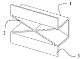
- the perspective view of 1st Embodiment of this invention (The ratio of the total area of a rib part is 18% with respect to the total area of the board of an open cross-section part).
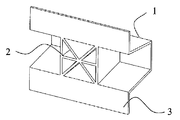
- the perspective view of 2nd Embodiment (the ratio of the total area of a rib part is 53% with respect to the total area of the board of an open cross-section part) of this invention.
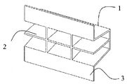
- the perspective view of 3rd Embodiment (The ratio of the total area of a rib part is 48% with respect to the total area of the board of an open cross-section part) of this invention.
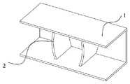
- the perspective view of 4th Embodiment (the ratio of the total area of a rib part is 44% with respect to the total area of the board of an open cross-section part) of this invention.
- the perspective view of 5th Embodiment (The ratio of the total area of a rib part is 65% with respect to the total area of the board of an open cross-section part) of this invention.
- the perspective view of 6th Embodiment (the ratio of the total area of a rib part is 25% with respect to the total area of the board of an open cross-section part) of this invention.
- the perspective view of 7th Embodiment of this invention (The ratio of the total area of a rib part is 42% with respect to the total area of the board of an open cross-section part).
- the perspective view of 8th Embodiment (The ratio of the total area of a rib part is 20% with respect to the total area of the board of an open cross-section part) of this invention.
- the perspective view of 9th Embodiment (The ratio of the total area of a rib part is 60% with respect to the total area of the board of an open cross-section part) of this invention.
- the perspective view of 10th Embodiment (The ratio of the total area of a rib part is 34% with respect to the total area of the board of an open cross-section part) of this invention.
- the perspective view of a comparison form The perspective view of a comparison form.
- the present invention is an impact-resistant member comprising an open cross-section portion and a rib portion inside the open cross-section portion, and at least one of the open cross-section portion and the rib portion is made of a carbon fiber reinforced composite material containing a thermoplastic resin, and the other is
- the impact-resistant member may be made of a thermoplastic resin.
- the carbon fiber reinforced composite material is preferably an isotropic material in which discontinuous carbon fibers are randomly oriented in the plane in the thermoplastic resin.
- the impact-resistant member of the present invention comprises an open cross-section portion and a rib portion inside the open cross-section portion, and at least one of the open cross-section portion and the rib portion is made of a carbon fiber reinforced composite material containing a thermoplastic resin, and the other is a heat
- An impact resistant member that may be made of a plastic resin, wherein the thermoplastic resin is present in the impact resistant member in an amount of 30 to 1000 parts by mass with respect to 100 parts by mass of the carbon fiber, The fiber length is 3 to 100 mm.
- thermoplastic resin contained in the carbon fiber reinforced composite material and the other may be the same type or a different type.
- both the open cross-section part and the rib part are made of a carbon fiber reinforced composite material, and the carbon fiber reinforced composite material forming the open cross-section part and the rib part is the same type. May be of different types.
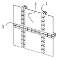
- FIG. 1 shows an example of an embodiment of the present invention. As shown in FIG. 1, an open cross section is denoted by 1 and a rib is denoted by 2.
- An open cross section is a structure whose cross section is configured in an open cross section such as a hat shape or a U-shape, and a pair of opposing surfaces (opposite surfaces) and edges of these pair of opposing surfaces And a bottom surface to be connected.
- a rib part is the site
- the inside of the open section is a portion that becomes hollow when the open section is temporarily closed.
- the rib portion is preferably provided so as to extend in the vertical direction with respect to the bottom surface inside the open section. It should be noted that extending in the direction perpendicular to the bottom surface does not have to be strictly perpendicular to the bottom surface, and an arbitrary angle or an angle for securing the draft angle of the mold is set so as not to impair the intention of the present invention. It is possible to take.
- the angle formed by the open cross section and the rib is preferably 30 to 90 degrees, and more preferably 40 to 90 degrees.
- Arbitrary chamfering and curvature can be added between the open cross-section part and the rib part to such an extent that the intention of the present invention is not impaired. There are no particular restrictions on the dimensions of the chamfer and curvature, but C is preferably 0.2 to 10 mm for chamfering, and R 0.2 to 10 mm for curvature.
- the rib portion may be formed integrally with the open cross-section portion.
- a carbon fiber composite material is used for the rib portion and a thermoplastic resin is used for the open cross-section portion, and then the rib portion is joined separately.
- the carbon fiber composite material is used to be integrally molded.
- the impact resistance performance here is not limited to the direction of impact load.
- the open cross-section portion is a structure that forms an open cross-section with a plurality of substantially planar plates, and refers to a portion that is the basis of the rib portion.
- FIG. 1 shows an example of an embodiment of the present invention, in which an open cross section is indicated by 1 and an open cross section is indicated by 4.
- the plate body is not limited to a flat plate but may be a so-called curved plate.
- Each surface of the open cross section need not be completely planar, and may have partial irregularities and beads.
- the height and width of the unevenness and bead are not particularly limited, but the height is preferably 0.5 to 2 times the thickness of the base open cross section. You may have a through-hole for ventilation, bolt fastening, wiring, etc.
- the impact-resistant member molded body
- the post-processing may be performed by drilling, punching, cutting, or the like.
- the thickness of the open cross section is not particularly limited, but is preferably 0.2 to 5 mm, and more preferably 1 to 3 mm.
- the plate thickness of the open cross section need not be uniform and can be locally increased or decreased.
- the increase / decrease width of the plate thickness is not particularly limited, but is preferably 30 to 300%, more preferably 50 to 200% of the plate thickness of the basic open cross section.
- the plate thickness can be changed stepwise, and can be continuously changed with a taper or a curvature, but it is preferably changed continuously from the viewpoint of avoiding stress concentration.
- the rib portion refers to a portion extending inside the above-described open cross-section portion, and is preferably a portion extending vertically inside the open cross-section portion. Moreover, it is preferable that the impact-resistant member of the present invention has a structure in which the rib portion connects the opposing surfaces (opposing surfaces) of the above-described open section. By installing the rib portion so as to connect the opposing surfaces of the open cross-section portion, it is possible to provide an impact resistant member that is superior in impact resistance.
- the structure in which the rib portion connects the opposing surfaces of the open cross section is not limited to the structure in which the opposing surfaces are directly connected by the same rib portion.
- the impact resistant member of the present invention preferably has two or more rib portions because the impact resistance becomes higher.
- the height of the rib portion is in a ratio of 5% to 100% with respect to the height of the opening portion from the bottom surface of the open section.
- the ratio of the height of the rib portion to the height of the opening portion of the open section is 70%.
- the height ratio of the rib part may be the ratio of the rib part height when the height of the opening is changed, with the lowest part being 100%. In a plurality of impact-resistant members, the ratio obtained using the height of the highest rib portion may be used. Furthermore, if the plate at the bottom of the open cross section of the impact resistant member is a curved plate with a cross section of an arc or the like, the height ratio of the rib portion is calculated from the height of the rib portion and opening with respect to the lowermost portion. It may be calculated.
- the impact resistant member of the present invention preferably has a rib portion that is perpendicular (or may be substantially perpendicular) to the plate of the open cross section.
- the rib portion is preferably perpendicular to the plate on the bottom surface inside the open cross section, and is preferably perpendicular to the plate on the opposite surface, and the impact resistance shown in FIG.
- a rib portion that is perpendicular to both the bottom plate and the opposite plate such as a member is preferable.
- the impact-resistant member of the present invention a member having a rib portion symmetric with respect to a plane orthogonal to the open cross-section portion is preferable.
- the surface perpendicular to the open cross section is, for example, a virtual surface that is perpendicular to the bottom plate in the impact resistant member of FIG. 1 and bisects between two opposing surfaces (two opposing surfaces). It is done.
- the rib is formed so that the ratio of the total area of the rib portion is 1% or more with respect to the total area of the plate body of the open section. If the total area of the rib portions is 1% or more, a more useful impact resistant member is preferable.
- the ratio of the total area of the rib portion may be 100%, that is, the total area of the plate body of the open cross-section portion may be equal to the total area of the rib portion.
- the ratio of the total area of the rib portions may exceed 100% by increasing the number of ribs, but a preferable range is 10 to 80%. In the example of the embodiment of the present invention shown in FIG.
- the height of the rib portion is not particularly limited, but is preferably 1 to 300 mm, and more preferably 5 to 100 mm.
- the height of the rib portion does not need to be uniform and can be locally increased or decreased.
- There is no particular limitation on the increase / decrease width of the rib height and 10 to 90% of the maximum height is preferably used, and 20 to 80% is more preferably used.
- the plate thickness of the rib portion is preferably 0.2 to 100 mm, more preferably 1 to 50 mm.
- the plate thickness of the rib portion does not need to be uniform and can be locally increased or decreased.
- the increase / decrease width is not particularly limited, but is preferably 20 to 500%, more preferably 50 to 200% of the thickness of the base rib portion.
- the plate thickness can be changed stepwise, and can be continuously changed with a taper or a curvature, but it is preferably changed continuously from the viewpoint of avoiding stress concentration.
- the draft angle of the mold is preferably 0 to 45 degrees, more preferably 0 to 10 degrees.
- the impact resistant member of the present invention further has a panel portion that is continuous with the end portion of the open section.
- the panel portion refers to a portion that is substantially planar and continues to the end of the open section.
- the panel part does not need to be completely planar, and may have partial unevenness and beads.
- the height and width of the unevenness and bead are not particularly limited, but the height is preferably 0.5 to 2 times the thickness of the base panel plate. You may have a through-hole for ventilation, bolt fastening, wiring, etc.
- the impact-resistant member (molded body) may be formed at the same time with the use of a shear or the like in the mold, and the post-processing may be performed by drilling, punching, cutting, or the like.
- the thickness of the panel portion is not particularly limited, but is preferably 0.2 to 5 mm, more preferably 1 to 3 mm.
- the thickness of the panel portion need not be uniform and can be locally increased or decreased. In this case, there is no particular restriction on the increase / decrease width of the plate thickness, but it is preferably 30 to 300%, more preferably 50 to 200% of the base panel thickness.
- the plate thickness can be changed stepwise, and can be continuously changed with a taper or a curvature, but it is preferably changed continuously from the viewpoint of avoiding stress concentration.
- the panel portion may be molded integrally with the open cross-section portion or may be joined after being molded separately, but is preferably molded integrally to improve impact resistance. Furthermore, it is preferable to use an impact-resistant member in which an open cross section, a rib portion, and a panel portion are integrally formed.
- the abundance of the thermoplastic resin in the impact resistant member of the present invention is 30 to 1000 parts by mass with respect to 100 parts by mass of the carbon fiber. More preferably, the thermoplastic resin is present in an amount of 30 to 500 parts by weight, more preferably 30 to 200 parts by weight, and particularly preferably 60 to 200 parts by weight with respect to 100 parts by weight of the carbon fibers. . More preferably, as the impact resistant member of the present invention, the whole including the open cross-section portion and the rib portion, and further the panel portion is made of carbon fiber reinforced composite material, and the heat in the carbon fiber reinforced composite material is The abundance of the plastic resin is 30 to 1000 parts by mass with respect to 100 parts by mass of the carbon fiber. Even more preferably, the thermoplastic resin is present in an amount of 30 to 500 parts by weight, more preferably 30 to 200 parts by weight, particularly preferably 60 to 200 parts by mass.
- thermoplastic resin used in the present invention is not particularly limited, but vinyl chloride resin, vinylidene chloride resin, vinyl acetate resin, polyvinyl alcohol resin, polystyrene resin, acrylonitrile-styrene resin (AS resin), acrylonitrile-butadiene-styrene.
- ABS resin acrylic resin, methacrylic resin, polyethylene resin, polypropylene resin, polyamide resin (for example, polyamide 6 resin, polyamide 11 resin, polyamide 12 resin, polyamide 46 resin, polyamide 66 resin, polyamide 610 resin), polyacetal resin , Polycarbonate resin, polyethylene terephthalate resin, polyethylene naphthalate resin, boribylene terephthalate resin, polyarylate resin, polyphenylene ether resin, polyphenylene At least one selected from the group consisting of a nylene sulfide resin, a polysulfone resin, a polyethersulfone resin, a polyetheretherketone resin, a polylactic acid resin, and a mixture (resin composition) of two or more selected from these resins Are preferred.
- the thermoplastic resin is preferably at least one selected from the group consisting of polycarbonate resin, polyester resin, polycarbonate, ABS resin, polyphenylene ether resin, polyamide resin and a mixture of two or more selected from these resins, and more preferably Is a polyamide resin or a polyester resin.
- the resin composition include polycarbonate resin and polyester resin composition, polycarbonate and ABS resin composition, polyphenylene ether resin and polyamide resin composition, polyamide resin and ABS resin composition, and polyester resin and polyamide resin. At least one selected from the group consisting of resin compositions and the like is more preferable.
- you may make a carbon fiber reinforced composite material and a thermoplastic resin contain a functional filler and additive. Examples include organic / inorganic fillers, flame retardants, UV-resistant agents, pigments, mold release agents, softeners, plasticizers, surfactants, and the like, but are not limited thereto.
- the carbon fibers contained in the carbon fiber composite material constituting the impact resistant member of the present invention are discontinuous having an average fiber length of 3 mm or more and 100 mm or less.
- an impact resistant member exhibiting high physical properties against shock loads and long-term fatigue loads.
- the average fiber length is less than 3 mm, there is a problem that the physical properties of the impact resistant member are lowered, and when it is longer than 100 mm, there is a problem that the handleability of the carbon fiber is deteriorated.
- the average fiber length of the carbon fibers is preferably 8 mm or more, more preferably 10 mm or more, still more preferably 15 mm or more, and still more preferably 20 mm or more. Moreover, the fiber length of the carbon fiber is preferably 80 mm or less, and more preferably 60 mm or less. A particularly preferable average fiber length is 8 mm to 80 mm.
- the carbon fiber contained in the carbon fiber reinforced composite material is represented by the following formula (1).
- Critical number of single yarns 600 / D (1) (Where D is the average fiber diameter ( ⁇ m) of the carbon fiber) It is preferable that the ratio of the carbon fiber bundle (A) constituted by the number of critical single yarns or more defined by the above is 20 Vol% or more and 99 Vol% or less with respect to the total amount of carbon fibers.
- the impact resistant member of the present invention is the carbon fiber bundle (A) in which the carbon fibers contained in the carbon fiber reinforced composite material are composed of the number of critical single yarns defined by the above formula (1) or more.
- the ratio with respect to the total amount of carbon fibers in the reinforced composite material is 20 Vol% or more and less than 99 Vol%, and the average number of fibers (N) in the carbon fiber bundle (A) satisfies the following formula (2). 0.7 ⁇ 10 4 / D 2 ⁇ N ⁇ 1 ⁇ 10 5 / D 2 (2) (Where D is the average fiber diameter ( ⁇ m) of the carbon fiber)
- the ratio of the carbon fiber bundle (A) is preferably 30 Vol% or more and less than 90 Vol%, and more preferably 30 Vol% or more and less than 80 Vol%.
- the impact resistant member of the present invention is a carbon fiber reinforced composite material constituting the carbon fiber bundle (A). It becomes a carbon fiber bundle (A) composed of the number of critical single yarns or more defined by the formula (1), and the remaining carbon fibers of 1 vol% or more and 80 vol% or less are in a single yarn state or less than the above critical single yarn number. The resulting fiber bundle is dispersed in the thermoplastic resin.
- the average number of fibers (N) in the carbon fiber bundle (A) composed of the critical single yarn or more satisfies the following formula (2).
- the surface is particularly smooth and has a uniform thickness, which is preferable. 0.7 ⁇ 10 4 / D 2 ⁇ N ⁇ 1 ⁇ 10 5 / D 2 (2) (Where D is the average fiber diameter ( ⁇ m) of the carbon fiber)
- the average number of fibers (N) in the carbon fiber bundle (A) is, specifically, when the average fiber diameter of the carbon fibers is 5 to 7 ⁇ m, the critical single yarn number is 86 to 120, and the average fiber diameter of the carbon fibers is Is 5 ⁇ m, the average number of fibers in the fiber bundle is in the range of more than 280 and less than 4000, with 600 to 2500 being preferred, and 600 to 1600 being more preferred.
- the average fiber diameter of the carbon fibers is 7 ⁇ m
- the average number of fibers in the fiber bundle is in the range of more than 142 and less than 2040, and in particular, it is preferably 300 to 1600. More preferably, the number is 300 to 800.
- the average number of fibers (N) in the carbon fiber bundle (A) is 0.7 ⁇ 10 4 / D 2 or less, it is difficult to obtain a high fiber volume content (Vf). Further, when the average number of fibers (N) in the carbon fiber bundle (A) is 1 ⁇ 10 5 / D 2 or more, a locally thick portion is generated, which may cause a void. As average fiber number (N) in said carbon fiber bundle (A), it is more preferable in following Formula (2 ') to satisfy
- the impact-resistant member of the present invention has a large tensile elastic modulus in an arbitrary direction in the bottom surface and a direction orthogonal to the same in the same surface (hereinafter sometimes referred to as a 0 degree direction and a 90 degree direction, respectively). It is preferable that a ratio obtained by dividing one value by the smaller value (hereinafter sometimes abbreviated as E ⁇ ) is 1.0 to 1.3.
- E ⁇ is an index of isotropic property of the material. When E ⁇ is less than 2, it is considered isotropic, and when it is 1.3 or less, isotropic property is particularly excellent.
- the impact-resistant member of the present invention includes an abundance of thermoplastic resin in the open cross section (mass part per 100 parts by mass of carbon fiber) and an abundance of thermoplastic resin in the rib part (mass part per 100 parts by mass of carbon fiber).
- Thermoplastic resin abundance ratio (%) 100 ⁇ (abundance of thermoplastic resin in rib portion ⁇ abundance of thermoplastic resin in open cross section) / abundance of thermoplastic resin in open cross section (i) Is preferably ⁇ 60% to + 45%, more preferably ⁇ 40% to + 30%, still more preferably ⁇ 20% to + 20%, and further preferably ⁇ 10% to + 10%.
- the impact-resistant member of the present invention has a thermoplastic resin abundance ratio of ⁇ 60% to 45%, and a tensile force in an arbitrary direction within the bottom surface of the open section and a direction orthogonal to the same plane. It is more preferable that the ratio of the elastic modulus obtained by dividing the larger value by the smaller value is 1.0 to 1.3.
- the abundance of the thermoplastic resin in the open cross-section portion and the rib portion in the impact resistant member is equal, and in an arbitrary direction in the bottom surface of the open cross-section portion and a direction orthogonal to this in the same plane It is more preferable that the ratio of the larger value of the tensile elastic modulus divided by the smaller value is 1.0 to 1.3.
- the impact resistant performance of the impact resistant member is preferably 4 ⁇ 10 11 (N 3 / g) or more, and more preferably 7 ⁇ 10 11 or more (N 3 / g). Preferably, it is 1 ⁇ 10 12 (N 3 / g).
- the impact resistance performance can be appropriately adjusted depending on the site where the impact resistance member is used, but if it is 4 ⁇ 10 11 (N 3 / g) or more, sufficient performance as an impact resistance member can be exhibited. There is no particular upper limit for impact resistance, but it is 5 ⁇ 10 13 (N 3 / g) or less, which is sufficient for many applications.
- the impact resistance performance can be evaluated by measuring the load resistance when the impact resistant member is compressed at high speed.
- the load resistance can be measured using, for example, a falling weight tester.
- a preferable method for producing the impact-resistant member of the present invention is a random mat composed of carbon fibers having an average fiber length of 3 mm or more and 100 mm or less and a thermoplastic resin, and the basis weight of the carbon fibers is 25 to 3000 g / m 2 .
- Critical number of single yarns 600 / D (1) (Where D is the average fiber diameter ( ⁇ m) of the carbon fiber)
- a production method in which press molding is performed using a carbon fiber bundle (A) composed of the number of critical single yarns or more defined in (1) with a ratio of 20 Vol% to 99 Vol% of the total amount of carbon fibers in the random mat. is there.
- a more preferable method for producing the impact resistant member of the present invention is composed of carbon fiber having a fiber length of 3 to 100 mm and a thermoplastic resin, and the carbon fiber has a basis weight of 25 to 3000 g / m 2.
- the ratio of the carbon fiber bundle (A) composed of the defined number of critical single yarns or more to the total amount of carbon fibers of the random mat is 20 Vol% or more and less than 99 Vol%, and the average number of fibers in the carbon fiber bundle (A) ( N) satisfies the formula (2), and is a manufacturing method for press-molding a random mat.
- an impact-resistant member having an open cross section and a rib by a single press molding, but after forming the open cross section and the rib separately, they are joined together.
- An impact-resistant member may be used, and one of the open cross-section portion and the rib portion may be obtained by press-molding a random mat as described above, and the other may be obtained by another method and joined together.
- the present invention includes a preferred method for producing such an impact resistant member.
- a relatively long carbon fiber having an average fiber length of 3 to 100 mm is filled with a thermoplastic resin having a high filling rate of 30 to 1000 parts by mass with respect to 100 parts by mass of carbon fiber, and the degree of freedom in shape is increased. It is possible to provide an impact resistant member that is high, excellent in impact resistance, and excellent in impact resistance to loads inputted from the length direction, the width direction, and the height direction.
- thermoplastic resin means a melting point when the thermoplastic resin is crystalline, and a glass transition point when the thermoplastic resin is amorphous.
- the random mat used in the method for producing an impact resistant member of the present invention is composed of carbon fibers having an average fiber length of 3 mm or more and 100 mm or less and a thermoplastic resin, and the weight of the carbon fibers is 25 to 3000 g / m 2 .
- the ratio of the carbon fiber bundle (A) composed of the number of critical single yarns or more defined by the above formula (1) to the total amount of fibers of the random mat is 20 Vol% or more and 99 Vol% or less, and the carbon fiber bundle (A) The average number of fibers (N) satisfies the above formula (2).
- the random mat refers to a material in which a thermoplastic resin adheres to a mat-like material in which carbon fibers are entangled.
- the details of the carbon fiber, the thermoplastic resin, and the carbon fiber bundle (A) in the random mat are as described above for the carbon fiber reinforced composite material constituting the impact resistant member.
- the carbon fibers are not oriented in a specific direction, but are distributed in a random direction.
- the random mat used in the production method of the present invention is preferably an isotropic material.
- the impact resistant member is obtained from the random mat, the isotropy of the carbon fibers in the random mat is maintained even in the impact resistant member.
- An impact resistant member having an E ⁇ of less than 2 is considered to be isotropic, and an impact resistant member having an E ⁇ of 1.3 or less is considered to be particularly excellent in isotropy.
- the ratio of the carbon fiber bundle (A) to the total amount of fibers of the random mat is less than 20 Vol%, an impact resistant member having excellent surface quality can be obtained. However, it is difficult to obtain an impact resistant member having excellent mechanical properties.
- the ratio of the carbon fiber bundle (A) in the random mat is preferably 30 Vol% or more and less than 90 Vol%, more preferably 30 Vol% or more and less than 80 Vol%.
- the average number of fibers (N) in the carbon fiber bundle (A) also satisfies the formula (2) for the random mat. preferable.
- a random mat having an average fiber number (N) of 0.7 ⁇ 10 4 / D 2 or less it is difficult to obtain an impact resistant member having a high carbon fiber volume content (Vf).
- a random mat having an average number of fibers (N) of 1 ⁇ 10 5 / D 2 or more it is more preferable in following Formula (2 ') to satisfy
- the production method of the present invention can provide impact resistant members having various thicknesses, but is particularly suitable for obtaining a thin impact resistant member having a thickness of about 0.2 to 1 mm.
- the thickness of the random mat used in the method for producing an impact resistant member of the present invention there is no particular limitation on the thickness of the random mat used in the method for producing an impact resistant member of the present invention, and a thickness of 1 to 150 mm can be obtained.
- the thickness is preferably 2 to 100 mm from the standpoint of exerting the effect of the present invention that a thinner impact resistant member can be obtained than the random mat of the present invention.
- the random mat may be used in the next step after the volume is reduced to an easy-to-use thickness using an appropriate pressurization or decompression device.
- the abundance of carbon fiber and thermoplastic resin contained in the random mat used in the method for producing an impact resistant member of the present invention is shown on a mass basis, it is preferably 30 to 1000 parts by mass, more preferably 100 parts by mass of carbon fiber. Is 30 to 500 parts by mass, more preferably 50 to 500 parts by mass, and still more preferably 60 to 200 parts by mass of the thermoplastic resin with respect to 100 parts by mass of the carbon fiber. If the ratio of the thermoplastic resin to 100 parts by mass of the carbon fiber is less than 30 parts by mass, voids are likely to be generated in the obtained carbon fiber reinforced composite material, and the strength and rigidity may be lowered. On the contrary, if the ratio of the thermoplastic resin is more than 1000 parts by mass, the reinforcing effect of the carbon fiber may be difficult to express.
- the random mat when performing cold press molding, the random mat is heated to a temperature not lower than the softening point of the thermoplastic resin contained therein and lower than the thermal decomposition temperature, that is, if the thermoplastic resin is crystalline, the random mat is higher than the melting point.
- the prepreg is impregnated with a thermoplastic resin by heating to a temperature lower than the thermal decomposition temperature, or in the case of amorphous, to a temperature not lower than the thermal decomposition temperature and used for molding.
- the form of the carbon fiber in the prepreg is kept in the random mat.
- the carbon fiber in the prepreg maintains the fiber length, isotropy, and degree of opening in the random mat, and is the same as that described in the random mat.
- the present invention comprises a carbon fiber having a fiber length of 3 to 100 mm and a thermoplastic resin, the carbon fiber having a basis weight of 25 to 3000 g / m 2 , and the critical single yarn number defined by the formula (1)
- the ratio of the carbon fiber bundle (A) constituted as described above to 20 vol% or more and less than 99 Vol% of the total amount of carbon fibers in the random mat, and the average number of fibers (N) in the carbon fiber bundle (A) is the above formula ( 2) Random mat characterized by satisfying 2), a prepreg obtained by heating to a temperature not lower than the thermal decomposition temperature above the softening point of the thermoplastic resin, characterized by being obtained by press molding the prepreg,
- the invention of the method of manufacturing the impact-resistant member is also included. More specifically, the above pyrolysis temperature is preferably the
- the impact-resistant member of the present invention is not limited to that shown in FIG. 1, and for example, the embodiment shown in FIGS.
- the present invention will be described more specifically with reference to examples, but the present invention is not limited thereto.
- the melting point of nylon 6 is 225 ° C.
- the thermal decomposition temperature (in air) is 300 ° C.
- the melting point of polybutylene terephthalate is 230 ° C.
- the thermal decomposition temperature (in air) is 300 ° C. is there.
- Random mat is cut out to about 100 mm x 100 mm. From the cut out random mat, all the fiber bundles are taken out with tweezers, and the number (I) of carbon fiber bundles (A) and the length (Li) and mass (Wi) of the carbon fiber bundle are measured and recorded. When the fiber bundle is so small that it cannot be taken out by tweezers, the mass is finally measured (Wk). For measuring the mass, a balance capable of measuring up to 1/100 mg (0.01 mg) is used. The number of critical single yarns is calculated from the fiber diameter (D) of the carbon fibers used in the random mat, and is divided into a carbon fiber bundle (A) having a number of critical single yarns or more and the other.
- the method for obtaining the average number of fibers (N) of the carbon fiber bundle (A) is as follows.
- the number of fibers (Ni) in each carbon fiber bundle is obtained from the following formula from the fineness (F) of the carbon fibers used.
- Ni Wi / (Li ⁇ F)
- the average number of fibers (N) in the carbon fiber bundle (A) is obtained from the number of bundles (I) of the carbon fiber bundle (A) by the following formula.
- the ratio (VR) of the carbon fiber bundle (A) to the total amount of fibers of the random mat can be obtained by the following equation using the density ( ⁇ ) of the carbon fibers.
- VR ⁇ (Wi / ⁇ ) ⁇ 100 / ((Wk + ⁇ Wi) / ⁇ )
- Carbon fiber as reinforcing fiber (manufactured by Toho Tenax Co., Ltd .: Tenax (registered trademark) STS40-24KS (fiber diameter: 7 ⁇ m) is cut to a fiber length of 10 mm while being widened to a width of 20 mm, and the supply amount of carbon fiber is tapered at 820 g / min. It introduced into the pipe
- Tenax (registered trademark) STS40-24KS (fiber diameter: 7 ⁇ m) is cut to a fiber length of 10 mm while being widened to a width of 20 mm, and the supply amount of carbon fiber is tapered at 820 g / min. It introduced into the pipe
- nylon 6 polyamide 6: hereinafter sometimes referred to as PA6
- PA6 polyamide 6
- Vf reinforcing fiber
- the average fiber length (La) was defined as 10 mm and the formula (1).
- the number of critical single yarns was 86
- the ratio of the reinforcing fiber bundle (A) to the total amount of fibers in the mat was 33%
- the average number of fibers (N) in the reinforcing fiber bundle (A) was 230.
- Carbon fiber as a reinforcing fiber (manufactured by Toho Tenax Co., Ltd .: Tenax (registered trademark) STS40-24KS (fiber diameter 7 ⁇ m) was cut into a length of 4 mm, and the carbon fiber supply rate was introduced into the tapered tube at 240 g / min. Air was blown onto the carbon fibers in the tube, and the fiber bundle was spread until it was almost completely formed into a single yarn, and then sprinkled on a table installed at the lower part of the tapered tube outlet.
- Tenax (registered trademark) STS40-24KS fiber diameter 7 ⁇ m
- nylon 6 resin (1015B manufactured by Ube Industries) frozen and pulverized to an average particle diameter of about 1 mm is supplied into a tapered tube at 1400 g / min and dispersed simultaneously with carbon fibers, so that carbon with an average fiber length of 4 mm is obtained.
- a random mat in which fibers and PA6 were mixed was obtained.
- This random mat had a reinforcing fiber (carbon fiber) volume content (Vf) of 10% and a basis weight of the reinforcing fiber of 260 g / m 2 .
- the average fiber length (La) and the ratio of the reinforcing fiber bundle (A) and the average number of fibers (N) of the obtained random mat were examined, the average fiber length was 4 mm and the critical unit defined by the formula (1) was used. The number of yarns was 86, and the reinforcing fiber bundle (A) was not observed. When the form of the reinforcing fiber in the obtained random mat was observed, the fiber axis of the reinforcing fiber was almost parallel to the surface and was randomly distributed in the surface.
- Carbon fiber as a reinforcing fiber (manufactured by Toho Tenax Co., Ltd .: Tenax (registered trademark) HTS40-12KS (fiber diameter 7 ⁇ m, fiber width 10 mm)) is cut into a fiber length of 30 mm, and the supply amount of carbon fiber is 950 g / min in a tapered tube The air was blown onto the carbon fiber in the taper tube, and the fiber bundle was partially opened to spread on the table installed at the lower part of the taper tube outlet.
- Tenax registered trademark
- HTS40-12KS fiber diameter 7 ⁇ m, fiber width 10 mm
- polybutylene terephthalate resin (hereinafter, referred to as PBT, sometimes referred to as PBT, DURANEX (registered trademark) 2002) frozen and ground to an average particle size of about 1 mm is supplied into the tapered tube at 1060 g / min as the matrix resin.
- PBT polybutylene terephthalate resin
- DURANEX registered trademark
- the average fiber length (La) was defined as 30 mm and the formula (1).
- the number of critical single yarns was 86
- the ratio of the reinforcing fiber bundle (A) to the total amount of fibers in the mat was 85%
- the average number of fibers (N) in the reinforcing fiber bundle (A) was 1500.
- Example 1 The random mat obtained in Reference Example 3 was hot-pressed at 260 ° C. and 4 MPa for 5 minutes using a Kawasaki Yoko press equipped with a flat plate mold for impregnation, cooled to 50 ° C., and carbon A prepreg having a weight per unit area of 1050 g / m 2 of a reinforcing fiber having 112 parts by mass of PBT with respect to 100 parts by mass of the fiber was obtained. Next, the obtained prepreg was heated to 260 ° C. using an IR oven made by NGK Kiln Tech and cold-pressed at a pressure of 10 MPa for 60 seconds to obtain a molded body (impact resistant member) as shown in FIG.
- the shape of the present embodiment is composed of an open cross section having a width of 40 mm, a length of 50 mm, a height of 22 mm, and a thickness of 2 mm, and a rib portion having a thickness of 2 mm.
- the average fiber length of the carbon fibers in the impact resistant member was 30 mm, the ratio of the carbon fiber bundle (A) was 85%, and the average number of fibers (N) in the carbon fiber bundle (A) was 1500.
- the abundance of the thermoplastic resin with respect to 100 parts by mass of the carbon fiber in the open cross section and the panel part is 112 parts by mass
- the abundance of the thermoplastic resin in the rib part is 112 parts by mass
- the ratio of the tensile modulus in the direction perpendicular to the same plane was 1.02.
- the impact resistance performance in this configuration is 1.6 ⁇ 10 12 N 3 / g, and this impact resistant member has an impact resistance to loads input from the length direction, the width direction, and the height direction. I found it excellent.
- Example 2 The random mat obtained in Reference Example 1 was hot-pressed at 260 ° C. and 4 MPa for 5 minutes using a Kawasaki Yoko press equipped with a flat plate mold for impregnation, then cooled to 50 ° C., and carbon A prepreg having a basis weight of 910 g / m 2 of a reinforcing fiber in which 122 parts by mass of PA6 is present with respect to 100 parts by mass of the fiber was obtained. Next, the obtained prepreg was heated to 260 ° C. using an IR oven manufactured by NGK Kiln Tech and cold-pressed at a pressure of 10 MPa for 60 seconds to obtain a molded body (impact resistant member) as shown in FIG.
- the shape of the present embodiment is composed of an open cross section having a width of 40 mm, a length of 50 mm, a height of 22 mm, and a thickness of 2 mm, and a rib portion having a thickness of 2 mm.
- the average fiber length of the carbon fibers in the impact resistant member was 10 mm, the ratio of the carbon fiber bundle (A) was 33%, and the average number of fibers (N) in the carbon fiber bundle (A) was 230.
- the abundance of the thermoplastic resin with respect to 100 parts by mass of the carbon fiber in the open section and the panel part is 122 parts by mass
- the abundance of the thermoplastic resin in the rib part is 122 parts by mass
- the ratio of the tensile elastic modulus in the direction perpendicular to the same plane was 1.05.
- the impact resistance performance in this configuration is 1.6 ⁇ 10 12 N 3 / g, and this impact resistant member has an impact resistance to loads input from the length direction, the width direction, and the height direction. I found it excellent.
- Example 1 From the random mat obtained in Reference Example 1, a prepreg was obtained in the same manner as in Example 2, and the obtained prepreg was heated to 260 ° C. using an IR oven made by NGK Kiln Tech and cold at a pressure of 30 MPa for 60 seconds.
- the impact-resistant member as shown in FIG. 11 was obtained by pressing.
- the shape of the present embodiment consists of an open cross section having a width of 40 mm, a length of 50 mm, a height of 22 mm and a thickness of 2 mm.
- the average fiber length of the carbon fibers in the impact resistant member was 10 mm, the ratio of the carbon fiber bundle (A) was 33%, and the average number of fibers (N) in the carbon fiber bundle (A) was 230.
- the abundance of the thermoplastic resin with respect to 100 parts by mass of the carbon fiber in the open cross-section part and the panel part is 122 parts by mass, and an arbitrary direction in the bottom surface of the open cross-section part and a tensile elastic modulus in a direction orthogonal to the same plane.
- the ratio was 1.05.
- the impact resistance performance in this configuration was 1.1 ⁇ 10 11 N 3 / g. Compared to this example, the structural rigidity was weak and the impact resistance performance was low.
- Example 3 The random mat obtained in Reference Example 2 was hot-pressed at 260 ° C. and 4 MPa for 5 minutes using a Kawasaki Yoko press equipped with a flat plate mold for impregnation, cooled to 50 ° C., and carbon A prepreg having a basis weight of 260 g / m 2 of a reinforcing fiber having 583 parts by mass of PA6 with respect to 100 parts by mass of the fiber was obtained. Next, the obtained prepreg was heated to 260 ° C. using an IR oven made by NGK Kiln Tech and cold-pressed at a pressure of 10 MPa for 60 seconds to obtain the same shape as in Example 2.
- the average fiber length of the carbon fibers in the impact resistant member was 4 mm, and no carbon fiber bundle (A) was observed.
- the abundance of the thermoplastic resin with respect to 100 parts by mass of the carbon fiber in the open cross section and the panel part is 583 parts by mass
- the abundance of the thermoplastic resin in the rib part is 583 parts by mass
- the ratio of the tensile modulus in the direction perpendicular to the same plane was 1.06.
- the impact resistance performance in this configuration was 3.2 ⁇ 10 11 N 3 / g.
- an impact resistant member that is lightweight, has a high degree of freedom in shape, and is excellent in impact resistance. Furthermore, the manufacturing method which can manufacture efficiently the impact-resistant member excellent in the impact resistance which is lightweight and high in shape is provided.
Abstract
Description
一方、特許文献2には合成樹脂を用いた構造体が示されている。この構造体は形状自由度が高く、リブを設けることで剛性を高くすることが出来るが、耐衝撃性が低く、大きな衝撃に対しては、構造体の質量が重くなってしまう。 From such a background, a large number of passenger space protection structures using a resin or a composite material have been disclosed. For example,
On the other hand,
本発明の耐衝撃部材は、開断面部とその内側にあるリブ部からなり、該開断面部と該リブ部のうち少なくとも一方は熱可塑性樹脂を含む炭素繊維強化複合材料からなり、他方は熱可塑性樹脂からなるものであってもよい耐衝撃部材であって、該耐衝撃部材における熱可塑性樹脂の存在量が、炭素繊維100質量部に対し30~1000質量部であり、該炭素繊維の平均繊維長が3~100mmであることを特徴とするものである。
本発明の耐衝撃部材が、開断面部とリブ部のうち一方が炭素繊維強化複合材料からなり、他方が熱可塑性樹脂からなる場合、炭素繊維強化複合材料に含まれる熱可塑性樹脂と、他方の熱可塑性樹脂とは同じ種類であっても別の種類であってもよい。
本発明の耐衝撃部材においては、開断面部とリブ部のいずれも炭素繊維強化複合材料からなるものであると好ましく、開断面部とリブ部をなす炭素繊維強化複合材料は同じ種類であっても異なる種類のものであってもよい。
図1に本発明の実施形態の例を示す。図1に図示のとおり、開断面部を1、リブ部を2で示す。
開断面部とは、断面がハット形状・コの字形状など開断面形状に構成された構造体であり、その内側に一対の対向する面(対向面)と、これら一対の対向面の縁をつなぐ底面とを有する。リブ部とは開断面部の内側に伸びた部位のことである。開断面部の内側とは、開断面部を仮に閉じた場合に中空となる部分のことである。 [Shock resistant member]
The impact-resistant member of the present invention comprises an open cross-section portion and a rib portion inside the open cross-section portion, and at least one of the open cross-section portion and the rib portion is made of a carbon fiber reinforced composite material containing a thermoplastic resin, and the other is a heat An impact resistant member that may be made of a plastic resin, wherein the thermoplastic resin is present in the impact resistant member in an amount of 30 to 1000 parts by mass with respect to 100 parts by mass of the carbon fiber, The fiber length is 3 to 100 mm.
In the impact-resistant member of the present invention, when one of the open section and the rib is made of a carbon fiber reinforced composite material and the other is made of a thermoplastic resin, the thermoplastic resin contained in the carbon fiber reinforced composite material and the other The thermoplastic resin may be the same type or a different type.
In the impact-resistant member of the present invention, it is preferable that both the open cross-section part and the rib part are made of a carbon fiber reinforced composite material, and the carbon fiber reinforced composite material forming the open cross-section part and the rib part is the same type. May be of different types.
FIG. 1 shows an example of an embodiment of the present invention. As shown in FIG. 1, an open cross section is denoted by 1 and a rib is denoted by 2.
An open cross section is a structure whose cross section is configured in an open cross section such as a hat shape or a U-shape, and a pair of opposing surfaces (opposite surfaces) and edges of these pair of opposing surfaces And a bottom surface to be connected. A rib part is the site | part extended inside the open cross-section part. The inside of the open section is a portion that becomes hollow when the open section is temporarily closed.
リブ部は開断面部と一体に成形されていても良いし、例えば、リブ部には炭素繊維複合材料を用い、開断面部には熱可塑性樹脂を用いるなどして別体で成形した後に接合されていても構わないが、耐衝撃性能を良くするために、炭素繊維複合材料を用いて、一体で成形されていることが好ましい。ここで言う耐衝撃性能は、衝撃荷重の方向に限定されない。 There is no restriction | limiting in the number of rib parts, One or more may be sufficient. There is no restriction | limiting in the kind of shape of a rib part, One type or several types may be combined.
The rib portion may be formed integrally with the open cross-section portion. For example, a carbon fiber composite material is used for the rib portion and a thermoplastic resin is used for the open cross-section portion, and then the rib portion is joined separately. However, in order to improve the impact resistance, it is preferable that the carbon fiber composite material is used to be integrally molded. The impact resistance performance here is not limited to the direction of impact load.
本発明の耐衝撃部材において、開断面部とは、実質的に面状である複数の板体により開断面を形成する構造体であり、リブ部の基礎となる部位のことを言う。図1に本発明の実施形態の例を示すが、開断面部を1、開断面部内側を4で示す。なお、上記の板体とは平板に限らず、いわゆる曲板であってもよい。 [Open cross section]
In the impact resistant member of the present invention, the open cross-section portion is a structure that forms an open cross-section with a plurality of substantially planar plates, and refers to a portion that is the basis of the rib portion. FIG. 1 shows an example of an embodiment of the present invention, in which an open cross section is indicated by 1 and an open cross section is indicated by 4. The plate body is not limited to a flat plate but may be a so-called curved plate.
本発明の耐衝撃部材において、リブ部とは、前述の開断面部の内側に伸びた部位のことを言い、開断面部の内側に垂直方向に伸びた部位であることが好ましい。
また、本発明の耐衝撃部材は、そのリブ部が前述の開断面部の対向している面(対向面)どうしをつなぐ構造を有するものであると好ましい。リブ部が開断面部の対向面をつなぐよう設置することで、耐衝撃性により優れた耐衝撃部材とすることができる。なお、上記の、リブ部が開断面部の対向面どうしをつなぐ構造とは、該対向面どうしが直接、同じリブ部によりつながれるものだけでなく、例えば、図7に示すように該対向面の間に壁状に設けられたリブ部と各々の対向面のリブ部がつながることにより、間接的に該対向面どうしがリブ部でつながる構造であっても良い。
本発明の耐衝撃部材としては、図1などに示すように、リブ部を2つ以上有するものであるとより耐衝撃性が高くなり好ましい。
本発明の耐衝撃部材としては、リブ部の高さが、開断面部の底面からの開口部の高さに対して5%~100%の割合にあると好ましい。例えば、図8に示す耐衝撃性部材における、リブ部の高さの開断面部の開口部の高さに対する比は70%である。
上記のリブ部の高さ割合としては、開口部の高さが変化している場合は、最も低いところを100%とした、リブ部の高さの割合でも良く、高さが異なるリブ部が複数ある耐衝撃部材においては、最も高いリブ部の高さを用いて求めた割合でもよい。更に、耐衝撃部材の開断面部の底面の板体が、断面が弧状などの曲板の場合は、最下部を基準とするリブ部や開口部の高さから、リブ部の高さ割合を算出してもよい。
本発明の耐衝撃部材としては、開断面部の板体に対して垂直(略垂直であってもよい)なリブ部を有するものであると好ましい。前記のとおり、開断面部の内側の底面にある板体に対して垂直なリブ部であると好ましく、また、対向面の板体に対して垂直であると好ましく、図2に示す耐衝撃性部材等のように底面の板体と対向面の板体のいずれにも垂直なリブ部であっても好ましい。
本発明の耐衝撃部材としては、開断面部に直行する面に対して対称なリブ部を有するものであっても好ましい。開断面部に直行する面とは、例えば、図1の耐衝撃部材において、底面の板体に直交し、対向する2面(2つの対向面)の中間で2等分する仮想面等があげられる。
本発明の耐衝撃部材としては、開断面部の板体の総面積に対して、リブ部の総面積の割合が1%以上となるようリブが形成されているものであると好ましい。リブ部の総面積が1%以上であると、より有用な耐衝撃部材となり好ましい。本発明の耐衝撃部材は、リブ部の総面積の割合が100%、つまり、開断面部の板体の総面積とリブ部の総面積とが等しいものであってもよく、また、極端にリブ数を増やすなどして、リブ部の総面積の割合が100%を超すものであってもよいが、好ましい範囲としては10~80%が挙げられる。
図1に示す本発明の実施形態の例において、リブ部を2で示す。リブ部の高さは特に制限はないが、1~300mmが好ましく、5~100mmが更に好ましい。リブ部の高さは均一である必要はなく、局所的に増減させることも可能である。リブ部高さの増減幅に特に制限はなく、最大高さの10~90%が好ましく用いられ、20~80%がさらに好ましく用いられる。リブ部の板厚に特に制限は無く、開断面部と同じであってもよく、異なっていても良い。
リブ部の板厚は0.2~100mmが好ましく、1~50mmがさらに好ましい。リブ部の板厚は均一である必要はなく、局所的に増減させることも可能である。この場合、増減幅に特に制限はないが、基礎となるリブ部板厚の20~500%が好ましく、50~200%がさらに好ましい。板厚は段階的に変化させることも可能であり、テーパーや曲率を持たせて連続的に変化させることも可能であるが、応力集中を回避するという観点から連続的に変化させるのが好ましい。また、リブ部には、本発明の意図を損なわない程度に、金型の抜き勾配を確保するための角度を設けることが好ましい。金型の抜き勾配は0~45度が好ましく、0~10度がさらに好ましい。 [Rib part]
In the impact resistant member of the present invention, the rib portion refers to a portion extending inside the above-described open cross-section portion, and is preferably a portion extending vertically inside the open cross-section portion.
Moreover, it is preferable that the impact-resistant member of the present invention has a structure in which the rib portion connects the opposing surfaces (opposing surfaces) of the above-described open section. By installing the rib portion so as to connect the opposing surfaces of the open cross-section portion, it is possible to provide an impact resistant member that is superior in impact resistance. The structure in which the rib portion connects the opposing surfaces of the open cross section is not limited to the structure in which the opposing surfaces are directly connected by the same rib portion. For example, as shown in FIG. A structure in which the opposing ribs are indirectly connected to each other by connecting the ribs provided in a wall shape between the ribs and the ribs of the respective facing surfaces.
As shown in FIG. 1 and the like, the impact resistant member of the present invention preferably has two or more rib portions because the impact resistance becomes higher.
In the impact resistant member of the present invention, it is preferable that the height of the rib portion is in a ratio of 5% to 100% with respect to the height of the opening portion from the bottom surface of the open section. For example, in the impact resistant member shown in FIG. 8, the ratio of the height of the rib portion to the height of the opening portion of the open section is 70%.
The height ratio of the rib part may be the ratio of the rib part height when the height of the opening is changed, with the lowest part being 100%. In a plurality of impact-resistant members, the ratio obtained using the height of the highest rib portion may be used. Furthermore, if the plate at the bottom of the open cross section of the impact resistant member is a curved plate with a cross section of an arc or the like, the height ratio of the rib portion is calculated from the height of the rib portion and opening with respect to the lowermost portion. It may be calculated.
The impact resistant member of the present invention preferably has a rib portion that is perpendicular (or may be substantially perpendicular) to the plate of the open cross section. As described above, the rib portion is preferably perpendicular to the plate on the bottom surface inside the open cross section, and is preferably perpendicular to the plate on the opposite surface, and the impact resistance shown in FIG. A rib portion that is perpendicular to both the bottom plate and the opposite plate such as a member is preferable.
As the impact-resistant member of the present invention, a member having a rib portion symmetric with respect to a plane orthogonal to the open cross-section portion is preferable. The surface perpendicular to the open cross section is, for example, a virtual surface that is perpendicular to the bottom plate in the impact resistant member of FIG. 1 and bisects between two opposing surfaces (two opposing surfaces). It is done.
As the impact resistant member of the present invention, it is preferable that the rib is formed so that the ratio of the total area of the rib portion is 1% or more with respect to the total area of the plate body of the open section. If the total area of the rib portions is 1% or more, a more useful impact resistant member is preferable. In the impact-resistant member of the present invention, the ratio of the total area of the rib portion may be 100%, that is, the total area of the plate body of the open cross-section portion may be equal to the total area of the rib portion. The ratio of the total area of the rib portions may exceed 100% by increasing the number of ribs, but a preferable range is 10 to 80%.
In the example of the embodiment of the present invention shown in FIG. The height of the rib portion is not particularly limited, but is preferably 1 to 300 mm, and more preferably 5 to 100 mm. The height of the rib portion does not need to be uniform and can be locally increased or decreased. There is no particular limitation on the increase / decrease width of the rib height, and 10 to 90% of the maximum height is preferably used, and 20 to 80% is more preferably used. There is no restriction | limiting in particular in the plate | board thickness of a rib part, It may be the same as an open cross-section part, and may differ.
The plate thickness of the rib portion is preferably 0.2 to 100 mm, more preferably 1 to 50 mm. The plate thickness of the rib portion does not need to be uniform and can be locally increased or decreased. In this case, the increase / decrease width is not particularly limited, but is preferably 20 to 500%, more preferably 50 to 200% of the thickness of the base rib portion. The plate thickness can be changed stepwise, and can be continuously changed with a taper or a curvature, but it is preferably changed continuously from the viewpoint of avoiding stress concentration. Moreover, it is preferable to provide the rib part with an angle for securing the draft angle of the mold so as not to impair the intention of the present invention. The draft angle of the mold is preferably 0 to 45 degrees, more preferably 0 to 10 degrees.
本発明の耐衝撃部材は、更に開断面部の端部に連続するパネル部を有することが好ましい。
本発明の耐衝撃部材において、パネル部とは、実質的に面状で開断面部の端部に連続する部位のことを言う。図1に示す本発明の実施形態の例において、パネル部を3で示す。パネル部は完全に面状である必要はなく、部分的な凹凸やビードを有していても良い。凹凸やビードの高さや幅に特に制限はないが、高さは基礎となるパネル部板厚の0.5~2倍とすることが好ましい。通気、ボルト締結、配線などのための貫通口を有しても良い。この場合、耐衝撃部材(成形体)の成形と同時に型内でシャーなどを用いて開孔させてもよく、後加工としてドリル、打ち抜き、切削加工などで開孔させても良い。パネル部の板厚は特に制限はないが、0.2~5mmが好ましく、1~3mmがさらに好ましい。パネル部の板厚は均一である必要はなく、局所的に増減させることも可能である。この場合、板厚の増減幅に特に制限はないが、基礎となるパネル部板厚の30~300%が好ましく、50~200%がさらに好ましい。板厚は段階的に変化させることも可能であり、テーパーや曲率を持たせて連続的に変化させることも可能であるが、応力集中を回避するという観点から連続的に変化させるのが好ましい。パネル部は開断面部と一体に成形されていても良いし、別体で成形した後に接合されていても構わないが、耐衝撃性能を良くするために一体で成形されていることが好ましい。さらには開断面部とリブ部とパネル部を一体成形した耐衝撃部材とすることが好ましい。 [Panel section]
It is preferable that the impact resistant member of the present invention further has a panel portion that is continuous with the end portion of the open section.
In the impact resistant member of the present invention, the panel portion refers to a portion that is substantially planar and continues to the end of the open section. In the example of the embodiment of the present invention shown in FIG. The panel part does not need to be completely planar, and may have partial unevenness and beads. The height and width of the unevenness and bead are not particularly limited, but the height is preferably 0.5 to 2 times the thickness of the base panel plate. You may have a through-hole for ventilation, bolt fastening, wiring, etc. In this case, the impact-resistant member (molded body) may be formed at the same time with the use of a shear or the like in the mold, and the post-processing may be performed by drilling, punching, cutting, or the like. The thickness of the panel portion is not particularly limited, but is preferably 0.2 to 5 mm, more preferably 1 to 3 mm. The thickness of the panel portion need not be uniform and can be locally increased or decreased. In this case, there is no particular restriction on the increase / decrease width of the plate thickness, but it is preferably 30 to 300%, more preferably 50 to 200% of the base panel thickness. The plate thickness can be changed stepwise, and can be continuously changed with a taper or a curvature, but it is preferably changed continuously from the viewpoint of avoiding stress concentration. The panel portion may be molded integrally with the open cross-section portion or may be joined after being molded separately, but is preferably molded integrally to improve impact resistance. Furthermore, it is preferable to use an impact-resistant member in which an open cross section, a rib portion, and a panel portion are integrally formed.
本発明の耐衝撃部材における、熱可塑性樹脂の存在量は、炭素繊維100質量部に対し、30~1000質量部である。より好ましくは、炭素繊維100質量部に対し、熱可塑性樹脂の存在量が30~500質量部であり、更に好ましくは、30~200質量部であり、特に好ましくは、60~200質量部である。
本発明の耐衝撃部材として、より好ましくは、開断面部およびリブ部、更にはパネル部もふくめた全体が炭素繊維強化複合材料によりなるものであり、かつ、その炭素繊維強化複合材料における、熱可塑性樹脂の存在量が、炭素繊維100質量部に対し、30~1000質量部となるものである。より一層好ましくは、炭素繊維100質量部に対し、熱可塑性樹脂の存在量が30~500質量部のものであり、更に好ましくは、30~200質量部のものであり、特に好ましくは、60~200質量部のものである。 [Thermoplastic resin]
The abundance of the thermoplastic resin in the impact resistant member of the present invention is 30 to 1000 parts by mass with respect to 100 parts by mass of the carbon fiber. More preferably, the thermoplastic resin is present in an amount of 30 to 500 parts by weight, more preferably 30 to 200 parts by weight, and particularly preferably 60 to 200 parts by weight with respect to 100 parts by weight of the carbon fibers. .
More preferably, as the impact resistant member of the present invention, the whole including the open cross-section portion and the rib portion, and further the panel portion is made of carbon fiber reinforced composite material, and the heat in the carbon fiber reinforced composite material is The abundance of the plastic resin is 30 to 1000 parts by mass with respect to 100 parts by mass of the carbon fiber. Even more preferably, the thermoplastic resin is present in an amount of 30 to 500 parts by weight, more preferably 30 to 200 parts by weight, particularly preferably 60 to 200 parts by mass.
上記の樹脂組成物としては、ポリカーボネート樹脂とポリエステル樹脂の組成物、ポリカーボネートとABS樹脂との組成物、ポリフェニレンエーテル樹脂とポリアミド樹脂の組成物、ポリアミド樹脂とABS樹脂の組成物、およびポリエステル樹脂とポリアミド樹脂の組成物等からなる群から選択された少なくとも1種が、より好ましい。
なお、本発明の目的を損なわない範囲で、炭素繊維強化複合材料や熱可塑性樹脂に機能性の充填材や添加剤を含有させても良い。例えば、有機/無機フィラー、難燃剤、耐UV剤、顔料、離型剤、軟化剤、可塑剤、界面活性剤などが挙げられるが、この限りではない。 The thermoplastic resin used in the present invention is not particularly limited, but vinyl chloride resin, vinylidene chloride resin, vinyl acetate resin, polyvinyl alcohol resin, polystyrene resin, acrylonitrile-styrene resin (AS resin), acrylonitrile-butadiene-styrene. Resin (ABS resin), acrylic resin, methacrylic resin, polyethylene resin, polypropylene resin, polyamide resin (for example, polyamide 6 resin, polyamide 11 resin, polyamide 12 resin, polyamide 46 resin, polyamide 66 resin, polyamide 610 resin), polyacetal resin , Polycarbonate resin, polyethylene terephthalate resin, polyethylene naphthalate resin, boribylene terephthalate resin, polyarylate resin, polyphenylene ether resin, polyphenylene At least one selected from the group consisting of a nylene sulfide resin, a polysulfone resin, a polyethersulfone resin, a polyetheretherketone resin, a polylactic acid resin, and a mixture (resin composition) of two or more selected from these resins Are preferred. The thermoplastic resin is preferably at least one selected from the group consisting of polycarbonate resin, polyester resin, polycarbonate, ABS resin, polyphenylene ether resin, polyamide resin and a mixture of two or more selected from these resins, and more preferably Is a polyamide resin or a polyester resin.
Examples of the resin composition include polycarbonate resin and polyester resin composition, polycarbonate and ABS resin composition, polyphenylene ether resin and polyamide resin composition, polyamide resin and ABS resin composition, and polyester resin and polyamide resin. At least one selected from the group consisting of resin compositions and the like is more preferable.
In addition, in the range which does not impair the objective of this invention, you may make a carbon fiber reinforced composite material and a thermoplastic resin contain a functional filler and additive. Examples include organic / inorganic fillers, flame retardants, UV-resistant agents, pigments, mold release agents, softeners, plasticizers, surfactants, and the like, but are not limited thereto.
本発明の耐衝撃部材を構成する炭素繊維複合材料に含まれる炭素繊維は、平均繊維長が3mm以上100mm以下の不連続なものである。これによって、静的な強度・剛性だけでなく、衝撃的な荷重や長期の疲労荷重に対しても高い物性を示す耐衝撃部材となる。平均繊維長が3mm未満であると、耐衝撃部材の物性が低くなるという問題があり、100mmより長いと炭素繊維の取扱い性が悪くなるという問題がある。炭素繊維の平均繊維長は8mm以上が好ましく、10mm以上がより好ましく、15mm以上がより一層好ましく、20mm以上が更に好ましい。また、炭素繊維の繊維長は80mm以下が好ましく、60mm以下がより好ましい。特に好ましい平均繊維長としては8mm~80mmが挙げられる。 [Carbon fibers contained in impact resistant members]
The carbon fibers contained in the carbon fiber composite material constituting the impact resistant member of the present invention are discontinuous having an average fiber length of 3 mm or more and 100 mm or less. As a result, not only static strength and rigidity, but also an impact resistant member exhibiting high physical properties against shock loads and long-term fatigue loads. When the average fiber length is less than 3 mm, there is a problem that the physical properties of the impact resistant member are lowered, and when it is longer than 100 mm, there is a problem that the handleability of the carbon fiber is deteriorated. The average fiber length of the carbon fibers is preferably 8 mm or more, more preferably 10 mm or more, still more preferably 15 mm or more, and still more preferably 20 mm or more. Moreover, the fiber length of the carbon fiber is preferably 80 mm or less, and more preferably 60 mm or less. A particularly preferable average fiber length is 8 mm to 80 mm.
臨界単糸数=600/D (1)
(ここでDは炭素繊維の平均繊維径(μm)である)
で定義される臨界単糸数以上で構成される炭素繊維束(A)の、炭素繊維全量に対する割合が20Vol%以上99Vol%以下であることが好ましい。
本発明の耐衝撃部材は、炭素繊維強化複合材料中に含まれる炭素繊維が、上記式(1)で定義される臨界単糸数以上で構成される炭素繊維束(A)のについて、該炭素繊維強化複合材料中の炭素繊維全量に対する割合が20Vol%以上99Vol%未満であり、かつ炭素繊維束(A)中の平均繊維数(N)が下記式(2)を満たすことがより好ましい。
0.7×10⁴ /D2 <N<1×10⁵ /D2 (2)
(ここでDは炭素繊維の平均繊維径(μm)である) In the impact resistant member of the present invention, the carbon fiber contained in the carbon fiber reinforced composite material is represented by the following formula (1).
Critical number of single yarns = 600 / D (1)
(Where D is the average fiber diameter (μm) of the carbon fiber)
It is preferable that the ratio of the carbon fiber bundle (A) constituted by the number of critical single yarns or more defined by the above is 20 Vol% or more and 99 Vol% or less with respect to the total amount of carbon fibers.
The impact resistant member of the present invention is the carbon fiber bundle (A) in which the carbon fibers contained in the carbon fiber reinforced composite material are composed of the number of critical single yarns defined by the above formula (1) or more. It is more preferable that the ratio with respect to the total amount of carbon fibers in the reinforced composite material is 20 Vol% or more and less than 99 Vol%, and the average number of fibers (N) in the carbon fiber bundle (A) satisfies the following formula (2).
0.7 × 10 4 / D 2 <N <1 × 10 5 / D 2 (2)
(Where D is the average fiber diameter (μm) of the carbon fiber)
0.7×10⁴/D2<N<1×105/D2(2)
(ここでDは炭素繊維の平均繊維径(μm)である) In addition, if another expression is made for the carbon fiber bundle (A), the impact resistant member of the present invention is a carbon fiber reinforced composite material constituting the carbon fiber bundle (A). It becomes a carbon fiber bundle (A) composed of the number of critical single yarns or more defined by the formula (1), and the remaining carbon fibers of 1 vol% or more and 80 vol% or less are in a single yarn state or less than the above critical single yarn number. The resulting fiber bundle is dispersed in the thermoplastic resin. In the carbon fiber reinforced composite material constituting the impact resistant member of the present invention, the average number of fibers (N) in the carbon fiber bundle (A) composed of the critical single yarn or more satisfies the following formula (2). Even in the case of an impact resistant member having a thin portion with a thickness of about 0.2 to 1 mm, the surface is particularly smooth and has a uniform thickness, which is preferable.
0.7 × 10 4 / D 2 <N <1 × 10 5 / D 2 (2)
(Where D is the average fiber diameter (μm) of the carbon fiber)
炭素繊維束(A)中の平均繊維数(N)が0.7×10⁴/D2以下の場合、高い繊維体積含有率(Vf)を得ることが困難となる。また炭素繊維束(A)中の平均繊維数(N)が1×105/D2以上の場合、局部的に厚い部分が生じ、ボイドの原因となる可能性がある。上記の炭素繊維束(A)中の平均繊維数(N)としては、以下式(2´)を満たすものであるとより好ましい。
0.7×10⁴/D2<N<6×104/D2(2´)
(ここでDは炭素繊維の平均繊維径(μm)である) Specifically, the average number of fibers (N) in the carbon fiber bundle (A) is, specifically, when the average fiber diameter of the carbon fibers is 5 to 7 μm, the critical single yarn number is 86 to 120, and the average fiber diameter of the carbon fibers is Is 5 μm, the average number of fibers in the fiber bundle is in the range of more than 280 and less than 4000, with 600 to 2500 being preferred, and 600 to 1600 being more preferred. When the average fiber diameter of the carbon fibers is 7 μm, the average number of fibers in the fiber bundle is in the range of more than 142 and less than 2040, and in particular, it is preferably 300 to 1600. More preferably, the number is 300 to 800.
When the average number of fibers (N) in the carbon fiber bundle (A) is 0.7 × 10 4 / D 2 or less, it is difficult to obtain a high fiber volume content (Vf). Further, when the average number of fibers (N) in the carbon fiber bundle (A) is 1 × 10 5 / D 2 or more, a locally thick portion is generated, which may cause a void. As average fiber number (N) in said carbon fiber bundle (A), it is more preferable in following Formula (2 ') to satisfy | fill.
0.7 × 10 4 / D 2 <N <6 × 10 4 / D 2 ( 2 ′ )
(Where D is the average fiber diameter (μm) of the carbon fiber)
熱可塑性樹脂存在量比(%)=100×(リブ部の熱可塑性樹脂の存在量-開断面部の熱可塑性樹脂の存在量)/開断面部の熱可塑性樹脂の存在量 (i)
で求められる熱可塑性樹脂存在量比が-60%~+45%であると好ましく、-40%~+30%であるとより好ましく、-20%~+20%であると更に好ましく、-10%~+10%であるとより一層好ましく、0%、つまり、開断面部とリブ部で熱可塑性樹脂存在量が等しいと特に好ましい。
本発明の耐衝撃部材は、上記の熱可塑性樹脂存在比が-60%~45%であり、かつ、開断面部の底面内の任意の方向及び同一面内でこれと直交する方向についての引張弾性率の、大きい方の値を小さい方の値で割った比が1.0~1.3であることがより好ましい。
本発明の耐衝撃部材は、該耐衝撃部材における開断面部及びリブ部の熱可塑性樹脂の存在量が等しく、開断面部の底面内の任意の方向及び同一面内でこれと直交する方向についての引張弾性率の、大きい方の値を小さい方の値で割った比が1.0~1.3であることがより好ましい。 The impact-resistant member of the present invention includes an abundance of thermoplastic resin in the open cross section (mass part per 100 parts by mass of carbon fiber) and an abundance of thermoplastic resin in the rib part (mass part per 100 parts by mass of carbon fiber). ) From the following formula (i)
Thermoplastic resin abundance ratio (%) = 100 × (abundance of thermoplastic resin in rib portion−abundance of thermoplastic resin in open cross section) / abundance of thermoplastic resin in open cross section (i)
Is preferably −60% to + 45%, more preferably −40% to + 30%, still more preferably −20% to + 20%, and further preferably −10% to + 10%. %, Even more preferably 0%, that is, it is particularly preferable if the amount of the thermoplastic resin present in the open cross section and the rib is equal.
The impact-resistant member of the present invention has a thermoplastic resin abundance ratio of −60% to 45%, and a tensile force in an arbitrary direction within the bottom surface of the open section and a direction orthogonal to the same plane. It is more preferable that the ratio of the elastic modulus obtained by dividing the larger value by the smaller value is 1.0 to 1.3.
In the impact resistant member of the present invention, the abundance of the thermoplastic resin in the open cross-section portion and the rib portion in the impact resistant member is equal, and in an arbitrary direction in the bottom surface of the open cross-section portion and a direction orthogonal to this in the same plane It is more preferable that the ratio of the larger value of the tensile elastic modulus divided by the smaller value is 1.0 to 1.3.
耐衝撃性能は、耐衝撃部材を高速圧縮した際の耐荷重を測定することで評価できる。すなわち、耐衝撃部材の長さ方向と幅方向と高さ方向の耐荷重の積を、耐衝撃部材の質量で割ることで、一方向以外の入力に対する性能も加味した評価を行うことができる。
耐荷重は、例えば、落錘試験機を用いて測定することができる。 In the impact resistant member of the present invention, the impact resistant performance of the impact resistant member is preferably 4 × 10 11 (N 3 / g) or more, and more preferably 7 × 10 11 or more (N 3 / g). Preferably, it is 1 × 10 12 (N 3 / g). The impact resistance performance can be appropriately adjusted depending on the site where the impact resistance member is used, but if it is 4 × 10 11 (N 3 / g) or more, sufficient performance as an impact resistance member can be exhibited. There is no particular upper limit for impact resistance, but it is 5 × 10 13 (N 3 / g) or less, which is sufficient for many applications.
The impact resistance performance can be evaluated by measuring the load resistance when the impact resistant member is compressed at high speed. That is, by dividing the product of the load resistance in the length direction, the width direction, and the height direction of the impact resistant member by the mass of the impact resistant member, it is possible to perform an evaluation taking into consideration the performance with respect to inputs other than one direction.
The load resistance can be measured using, for example, a falling weight tester.
本発明の耐衝撃部材の好ましい製造方法は、平均繊維長が3mm以上100mm以下の炭素繊維と熱可塑性樹脂とから構成されるランダムマットであって、炭素繊維が25~3000g/m2の目付であり、下記式(1)
臨界単糸数=600/D (1)
(ここでDは炭素繊維の平均繊維径(μm)である)
で定義される臨界単糸数以上で構成される炭素繊維束(A)の、ランダムマット中の炭素繊維全量に対する割合が20Vol%以上99Vol%以下であるものを用いて、プレス成形を行う製造方法である。
本発明の耐衝撃部材のより好ましい製造方法は、繊維長3~100mmの炭素繊維と熱可塑性樹脂とから構成され、炭素繊維が25~3000g/m2の目付けであり、上記式(1)で定義される臨界単糸数以上で構成される炭素繊維束(A)の、ランダムマットの炭素繊維全量に対する割合が20Vol%以上99Vol%未満であり、かつ炭素繊維束(A)中の平均繊維数(N)が前記式(2)を満たすことを特徴とするランダムマットをプレス成形する製造方法である。
製造効率からは、1回のプレス成形にて、開断面部とリブ部を有する耐衝撃部材を得るのが好ましいが、開断面部とリブ部を別々に成形してから、これらを接合して耐衝撃部材としても良く、開断面部とリブ部のうち一方を上記のとおりランダムマットをプレス成形して得て、他方は別の方法により得て、これらを接合しても良い。
本発明はこのような耐衝撃部材の好ましい製造方法を包含する。本発明により平均繊維長が3~100mmといった比較的長い炭素繊維を、熱可塑性樹脂の存在量が、炭素繊維100質量部に対し30~1000質量部といった高充填率で満たして、形状自由度が高く、耐衝撃性に優れ、さらには長さ方向、幅方向、高さ方向のそれぞれから入力された荷重への耐衝撃性に優れる耐衝撃部材を提供できる。 <Method for producing impact resistant member>
A preferable method for producing the impact-resistant member of the present invention is a random mat composed of carbon fibers having an average fiber length of 3 mm or more and 100 mm or less and a thermoplastic resin, and the basis weight of the carbon fibers is 25 to 3000 g / m 2 . Yes, the following formula (1)
Critical number of single yarns = 600 / D (1)
(Where D is the average fiber diameter (μm) of the carbon fiber)
A production method in which press molding is performed using a carbon fiber bundle (A) composed of the number of critical single yarns or more defined in (1) with a ratio of 20 Vol% to 99 Vol% of the total amount of carbon fibers in the random mat. is there.
A more preferable method for producing the impact resistant member of the present invention is composed of carbon fiber having a fiber length of 3 to 100 mm and a thermoplastic resin, and the carbon fiber has a basis weight of 25 to 3000 g / m 2. The ratio of the carbon fiber bundle (A) composed of the defined number of critical single yarns or more to the total amount of carbon fibers of the random mat is 20 Vol% or more and less than 99 Vol%, and the average number of fibers in the carbon fiber bundle (A) ( N) satisfies the formula (2), and is a manufacturing method for press-molding a random mat.
From the viewpoint of production efficiency, it is preferable to obtain an impact-resistant member having an open cross section and a rib by a single press molding, but after forming the open cross section and the rib separately, they are joined together. An impact-resistant member may be used, and one of the open cross-section portion and the rib portion may be obtained by press-molding a random mat as described above, and the other may be obtained by another method and joined together.
The present invention includes a preferred method for producing such an impact resistant member. According to the present invention, a relatively long carbon fiber having an average fiber length of 3 to 100 mm is filled with a thermoplastic resin having a high filling rate of 30 to 1000 parts by mass with respect to 100 parts by mass of carbon fiber, and the degree of freedom in shape is increased. It is possible to provide an impact resistant member that is high, excellent in impact resistance, and excellent in impact resistance to loads inputted from the length direction, the width direction, and the height direction.
本発明の耐衝撃部材の製造方法にて用いられるランダムマットは、平均繊維長が3mm以上100mm以下の炭素繊維と熱可塑性樹脂とから構成され、炭素繊維が25~3000g/m2の目付であり、前記式(1)で定義される臨界単糸数以上で構成される炭素繊維束(A)の、ランダムマットの繊維全量に対する割合が20Vol%以上99Vol%以下であり、かつ炭素繊維束(A)中の平均繊維数(N)が前記式(2)を満たすものである。
本発明において、ランダムマットとは、炭素繊維が絡みあったマット状物に熱可塑性樹脂が付着した物を指す。 <Random mat>
The random mat used in the method for producing an impact resistant member of the present invention is composed of carbon fibers having an average fiber length of 3 mm or more and 100 mm or less and a thermoplastic resin, and the weight of the carbon fibers is 25 to 3000 g / m 2 . The ratio of the carbon fiber bundle (A) composed of the number of critical single yarns or more defined by the above formula (1) to the total amount of fibers of the random mat is 20 Vol% or more and 99 Vol% or less, and the carbon fiber bundle (A) The average number of fibers (N) satisfies the above formula (2).
In the present invention, the random mat refers to a material in which a thermoplastic resin adheres to a mat-like material in which carbon fibers are entangled.
ランダムマットの面内において、炭素繊維は特定の方向に配向しておらず、無作為な方向に分散して配置されている。本発明の製造方法で用いられるランダムマットは等方性の材料であることが好ましい。ランダムマットより耐衝撃部材を得た場合に、ランダムマット中の炭素繊維の等方性は、耐衝撃部材においても維持される。ランダムマットより耐衝撃部材を得て、該耐衝撃部材について、互いに直交する二方向の引張弾性率の大きい方の値の小さい方の値に対する比(Eδ)を求めることで、ランダムマットおよびそれから得られる耐衝撃部材の等方性を定量的に評価できる。Eδが2未満である耐衝撃部材は等方性とされ、1.3以下である耐衝撃部材は特に等方性が優れているとされる。 The details of the carbon fiber, the thermoplastic resin, and the carbon fiber bundle (A) in the random mat are as described above for the carbon fiber reinforced composite material constituting the impact resistant member.
In the plane of the random mat, the carbon fibers are not oriented in a specific direction, but are distributed in a random direction. The random mat used in the production method of the present invention is preferably an isotropic material. When the impact resistant member is obtained from the random mat, the isotropy of the carbon fibers in the random mat is maintained even in the impact resistant member. Obtaining an impact resistant member from the random mat, and obtaining the ratio (Eδ) of the larger value of the tensile modulus of elasticity in two directions perpendicular to each other to the smaller value (Eδ) for the impact resistant member. It is possible to quantitatively evaluate the isotropy of the impact resistant member. An impact resistant member having an Eδ of less than 2 is considered to be isotropic, and an impact resistant member having an Eδ of 1.3 or less is considered to be particularly excellent in isotropy.
0.7×10⁴/D2<N<6×104/D2(2´)
(ここでDは炭素繊維の平均繊維径(μm)である) As described for the carbon fiber composite material constituting the impact resistant member of the present invention, the average number of fibers (N) in the carbon fiber bundle (A) also satisfies the formula (2) for the random mat. preferable. When a random mat having an average fiber number (N) of 0.7 × 10 4 / D 2 or less is used, it is difficult to obtain an impact resistant member having a high carbon fiber volume content (Vf). In addition, when a random mat having an average number of fibers (N) of 1 × 10 5 / D 2 or more is used, a locally thick portion is generated, which tends to cause voids. As average fiber number (N) in said carbon fiber bundle (A), it is more preferable in following Formula (2 ') to satisfy | fill.
0.7 × 10 4 / D 2 <N <6 × 10 4 / D 2 ( 2 ′ )
(Where D is the average fiber diameter (μm) of the carbon fiber)
本発明において、コールドプレス成形を行う場合、ランダムマットを、その含有する熱可塑性樹脂の軟化点以上熱分解温度未満の温度まで加熱、つまり、熱可塑性樹脂が結晶性の場合はランダムマットを融点以上熱分解温度未満の温度まで、非晶性の場合はガラス転移温度以上熱分解温度未満の温度まで加熱することで、熱可塑性樹脂を含浸させプリプレグを得て成形に用いる。プリプレグにおける炭素繊維の形態はランダムマット中における状態を保っている。すなわち、プリプレグ中の炭素繊維はランダムマットにおける繊維長や等方性、開繊程度を維持しており、上記のランダムマットに記載したものと同様である。
つまり、本発明には、繊維長3~100mmの炭素繊維と熱可塑性樹脂とから構成され、炭素繊維が25~3000g/m2 の目付けであり、前記式(1)で定義される臨界単糸数以上で構成される炭素繊維束(A)の、ランダムマットの炭素繊維全量に対する割合が20Vol%以上99Vol%未満であり、かつ炭素繊維束(A)中の平均繊維数(N)が前記式(2)を満たすことを特徴とするランダムマットを、熱可塑性樹脂の軟化点以上熱分解温度未満の温度まで加熱して得られるプリプレグとし、該プリプレグをプレス成形して得ることを特徴とする、前記の耐衝撃部材を製造する方法の発明も包含される。
なお、上記の熱分解温度についてより具体的に言うと空気中の熱分解温度であると好ましい。 <Prepreg>
In the present invention, when performing cold press molding, the random mat is heated to a temperature not lower than the softening point of the thermoplastic resin contained therein and lower than the thermal decomposition temperature, that is, if the thermoplastic resin is crystalline, the random mat is higher than the melting point. In the case of amorphous, the prepreg is impregnated with a thermoplastic resin by heating to a temperature lower than the thermal decomposition temperature, or in the case of amorphous, to a temperature not lower than the thermal decomposition temperature and used for molding. The form of the carbon fiber in the prepreg is kept in the random mat. That is, the carbon fiber in the prepreg maintains the fiber length, isotropy, and degree of opening in the random mat, and is the same as that described in the random mat.
That is, the present invention comprises a carbon fiber having a fiber length of 3 to 100 mm and a thermoplastic resin, the carbon fiber having a basis weight of 25 to 3000 g / m 2 , and the critical single yarn number defined by the formula (1) The ratio of the carbon fiber bundle (A) constituted as described above to 20 vol% or more and less than 99 Vol% of the total amount of carbon fibers in the random mat, and the average number of fibers (N) in the carbon fiber bundle (A) is the above formula ( 2) Random mat characterized by satisfying 2), a prepreg obtained by heating to a temperature not lower than the thermal decomposition temperature above the softening point of the thermoplastic resin, characterized by being obtained by press molding the prepreg, The invention of the method of manufacturing the impact-resistant member is also included.
More specifically, the above pyrolysis temperature is preferably the pyrolysis temperature in air.
ランダムマットを100mm×100mm程度に切り出す。切り出したランダムマットより、繊維束をピンセットで全て取り出し、炭素繊維束(A)の束の数(I)および炭素繊維束の長さ(Li)と質量(Wi)を測定し、記録する。ピンセットにて取り出すことができない程度に繊維束が小さいものについては、まとめて最後に質量を測定する(Wk)。質量の測定には、1/100mg(0.01mg)まで測定可能な天秤を用いる。
ランダムマットに使用している炭素繊維の繊維径(D)より、臨界単糸数を計算し、臨界単糸数以上の炭素繊維束(A)と、それ以外に分ける。なお、2種類以上の炭素繊維が使用されている場合には、繊維の種類毎に分け、各々について測定及び評価を行う。
炭素繊維束(A)の平均繊維数(N)の求め方は以下の通りである。
各炭素繊維束中の繊維本数(Ni)は使用している炭素繊維の繊度(F)より、次式により求められる。
Ni=Wi/(Li×F)
炭素繊維束(A)中の平均繊維数(N)は、炭素繊維束(A)の束の数(I)より、次式により求められる。
N=ΣNi/I
炭素繊維束(A)のランダムマットの繊維全量に対する割合(VR)は、炭素繊維の密度(ρ)を用いて次式により求められる。
VR=Σ(Wi/ρ)×100/((Wk+ΣWi)/ρ) 1) Analysis of carbon fiber bundle in random mat Random mat is cut out to about 100 mm x 100 mm. From the cut out random mat, all the fiber bundles are taken out with tweezers, and the number (I) of carbon fiber bundles (A) and the length (Li) and mass (Wi) of the carbon fiber bundle are measured and recorded. When the fiber bundle is so small that it cannot be taken out by tweezers, the mass is finally measured (Wk). For measuring the mass, a balance capable of measuring up to 1/100 mg (0.01 mg) is used.
The number of critical single yarns is calculated from the fiber diameter (D) of the carbon fibers used in the random mat, and is divided into a carbon fiber bundle (A) having a number of critical single yarns or more and the other. In addition, when two or more types of carbon fibers are used, it is divided for each type of fiber, and measurement and evaluation are performed for each.
The method for obtaining the average number of fibers (N) of the carbon fiber bundle (A) is as follows.
The number of fibers (Ni) in each carbon fiber bundle is obtained from the following formula from the fineness (F) of the carbon fibers used.
Ni = Wi / (Li × F)
The average number of fibers (N) in the carbon fiber bundle (A) is obtained from the number of bundles (I) of the carbon fiber bundle (A) by the following formula.
N = ΣNi / I
The ratio (VR) of the carbon fiber bundle (A) to the total amount of fibers of the random mat can be obtained by the following equation using the density (ρ) of the carbon fibers.
VR = Σ (Wi / ρ) × 100 / ((Wk + ΣWi) / ρ)
得られた耐衝撃部材に含まれる炭素繊維の平均繊維長は、500℃×1時間程度、炉内にて樹脂を除去した後、無作為に抽出した炭素繊維100本の長さをノギスおよびルーペで1mm単位まで測定して記録し、測定した全ての炭素繊維の長さ(Li、ここでi=1~100の整数)から、次式により平均繊維長(La)を求めた。
La=ΣLi/100
なお、ランダムマット中の炭素繊維の平均繊維長についても上記と同様の方法で測定することができる。 2) Analysis of average fiber length of carbon fiber contained in impact-resistant member After the resin was removed in the furnace for about 500 ° C. × 1 hour, the average fiber length of carbon fiber contained in the obtained impact-resistant member was The length of 100 randomly extracted carbon fibers was measured and recorded to the nearest 1 mm with a caliper and loupe. From the measured lengths of all carbon fibers (Li, where i = 1 to an integer of 1 to 100), The average fiber length (La) was determined by the following formula.
La = ΣLi / 100
The average fiber length of carbon fibers in the random mat can also be measured by the same method as described above.
耐衝撃部材について、500℃×1時間程度、炉内にて樹脂を除去した後、上記のランダムマットにおける方法と同様にして測定した。 3) Analysis of carbon fiber bundle in impact resistant member The impact resistant member was measured in the same manner as in the above random mat after removing the resin in the furnace for about 500 ° C. for about 1 hour.
耐衝撃部材の開断面部、パネル部及びリブ部より試験片を切出し、それぞれ500℃×1時間、炉内にて樹脂を燃焼除去し、処理前後の試料の質量を秤量することによって炭素繊維分と樹脂分の質量を算出した。 4) Analysis of abundance of fiber and resin in impact resistant member Cut out test pieces from open cross section, panel portion and rib portion of impact resistant member, and burn and remove resin in furnace at 500 ° C for 1 hour, The mass of the carbon fiber content and the resin content was calculated by weighing the mass of the sample before and after the treatment.
ウォータージェットを用いて耐衝撃部材から試験片を切出し、開断面部の底面内の任意の方向及び同一面内でこれと直交する方向について、A&D社製のテンシロン万能試験機を用いて、引張弾性率を測定し、大きい方の値を小さい方の値で割った比を算出した。 5) Tensile modulus test Tensylon universal testing machine manufactured by A & D Co., Ltd. for any direction in the bottom of the open section and in the direction perpendicular to the same in the same plane using a water jet. Was used to measure the tensile modulus, and the ratio of the larger value divided by the smaller value was calculated.
落錘試験機を用いて、耐衝撃部材を高速圧縮した際の耐荷重を測定した。一方向以外の入力に対する性能も加味した評価を行うために、長さ方向と幅方向と高さ方向の耐荷重の積を部材質量で割った値により評価を行った。 6) Impact resistance evaluation method Using a falling weight tester, the load resistance when the impact resistant member was compressed at high speed was measured. In order to perform an evaluation taking into account the performance with respect to inputs other than one direction, the evaluation was performed by a value obtained by dividing the product of the load resistance in the length direction, the width direction, and the height direction by the member mass.
強化繊維としての炭素繊維(東邦テナックス社製:テナックス(登録商標)STS40-24KS(繊維径7μm)を20mm幅に広げながら、繊維長10mmにカットし、炭素繊維の供給量を820g/分でテーパー管内に導入し、テーパー管内で空気を炭素繊維に吹き付けて繊維束を部分的に開繊しつつ、テーパー管出口の下部に設置したテーブル上に散布した。
また、マトリックス樹脂として、平均粒径が約1mmに冷凍粉砕したナイロン6(ポリアミド6:以下PA6と記載することがある)樹脂(宇部興産製 1015B)を1000g/分でテーパー管内に供給し、炭素繊維と同時に散布することで、平均繊維長10mmの炭素繊維とPA6が混合されたランダムマットを得た。このランダムマットの強化繊維(炭素繊維)体積含有率(Vf)は35%、強化繊維の目付は910g/m2であった。得られたランダムマットの平均繊維長(La)及び強化繊維束(A)の割合と、平均繊維数(N)を調べたところ、平均繊維長(La)は10mm、式(1)で定義される臨界単糸数は86であり、強化繊維束(A)の、マットの繊維全量に対する割合は33%、強化繊維束(A)中の平均繊維数(N)は230であった。ランダムマットにおける強化繊維の形態を観察したところ、強化繊維の繊維軸は面とほぼ平行にあり、面内においては無作為に分散されていた。 [Reference Example 1]
Carbon fiber as reinforcing fiber (manufactured by Toho Tenax Co., Ltd .: Tenax (registered trademark) STS40-24KS (fiber diameter: 7 μm) is cut to a fiber length of 10 mm while being widened to a width of 20 mm, and the supply amount of carbon fiber is tapered at 820 g / min. It introduced into the pipe | tube, and it sprayed on the table installed in the lower part of the taper pipe | tube exit, spraying air on carbon fiber in a taper pipe | tube, and opening a fiber bundle partially.
Further, as a matrix resin, nylon 6 (polyamide 6: hereinafter sometimes referred to as PA6) resin (Ube Industries 1015B) frozen and pulverized to an average particle size of about 1 mm is supplied into the tapered tube at 1000 g / min, and carbon By spreading simultaneously with the fibers, a random mat in which carbon fibers having an average fiber length of 10 mm and PA6 were mixed was obtained. This random mat had a reinforcing fiber (carbon fiber) volume content (Vf) of 35%, and the basis weight of the reinforcing fiber was 910 g / m 2 . When the average fiber length (La) and the ratio of the reinforcing fiber bundle (A) and the average number of fibers (N) of the obtained random mat were examined, the average fiber length (La) was defined as 10 mm and the formula (1). The number of critical single yarns was 86, the ratio of the reinforcing fiber bundle (A) to the total amount of fibers in the mat was 33%, and the average number of fibers (N) in the reinforcing fiber bundle (A) was 230. When the form of the reinforcing fiber in the random mat was observed, the fiber axis of the reinforcing fiber was almost parallel to the surface and was randomly distributed in the surface.
強化繊維としての炭素繊維(東邦テナックス社製:テナックス(登録商標)STS40-24KS(繊維径7μm)を長さ4mmにカットし、炭素繊維の供給量を240g/分でテーパー管内に導入し、テーパー管内で空気を炭素繊維に吹き付けて繊維束をほぼ完全に単糸状になるまで開繊しつつ、テーパー管出口の下部に設置したテーブル上に散布した。
またマトリックス樹脂として、平均粒径が約1mmに冷凍粉砕したナイロン6樹脂(宇部興産製 1015B)を1400g/分でテーパー管内に供給し、炭素繊維と同時に散布することで、平均繊維長4mmの炭素繊維とPA6が混合されたランダムマットを得た。このランダムマットの強化繊維(炭素繊維)体積含有率(Vf)は10%、強化繊維の目付は260g/m2であった。得られたランダムマットの平均繊維長(La)及び強化繊維束(A)の割合と、平均繊維数(N)を調べたところ、平均繊維長は4mm、式(1)で定義される臨界単糸数は86であり、強化繊維束(A)は観測されなかった。得られたランダムマットにおける強化繊維の形態を観察したところ、強化繊維の繊維軸は面とほぼ平行にあり、面内においては無作為に分散されていた。 [Reference Example 2]
Carbon fiber as a reinforcing fiber (manufactured by Toho Tenax Co., Ltd .: Tenax (registered trademark) STS40-24KS (fiber diameter 7 μm) was cut into a length of 4 mm, and the carbon fiber supply rate was introduced into the tapered tube at 240 g / min. Air was blown onto the carbon fibers in the tube, and the fiber bundle was spread until it was almost completely formed into a single yarn, and then sprinkled on a table installed at the lower part of the tapered tube outlet.
In addition, as a matrix resin, nylon 6 resin (1015B manufactured by Ube Industries) frozen and pulverized to an average particle diameter of about 1 mm is supplied into a tapered tube at 1400 g / min and dispersed simultaneously with carbon fibers, so that carbon with an average fiber length of 4 mm is obtained. A random mat in which fibers and PA6 were mixed was obtained. This random mat had a reinforcing fiber (carbon fiber) volume content (Vf) of 10% and a basis weight of the reinforcing fiber of 260 g / m 2 . When the average fiber length (La) and the ratio of the reinforcing fiber bundle (A) and the average number of fibers (N) of the obtained random mat were examined, the average fiber length was 4 mm and the critical unit defined by the formula (1) was used. The number of yarns was 86, and the reinforcing fiber bundle (A) was not observed. When the form of the reinforcing fiber in the obtained random mat was observed, the fiber axis of the reinforcing fiber was almost parallel to the surface and was randomly distributed in the surface.
強化繊維としての炭素繊維(東邦テナックス社製:テナックス(登録商標)HTS40-12KS(繊維径7μm、繊維幅10mm))を繊維長30mmにカットし、炭素繊維の供給量を950g/分でテーパー管内に導入し、テーパー管内で空気を炭素繊維に吹き付けて繊維束を部分的に開繊しつつ、テーパー管出口の下部に設置したテーブル上に散布した。
また、マトリックス樹脂として、平均粒径が約1mmに冷凍粉砕したポリブチレンテレフタレート樹脂(以下PBTと記載することがある、ポリプラスチック製 DURANEX(登録商標)2002)を1060g/分でテーパー管内に供給し、炭素繊維と同時に散布することで、平均繊維長30mmの炭素繊維とPBTが混合されたランダムマットを得た。このランダムマットの強化繊維(炭素繊維)体積含有率(Vf)は40%、強化繊維の目付は1050g/m2であった。得られたランダムマットの平均繊維長(La)及び強化繊維束(A)の割合と、平均繊維数(N)を調べたところ、平均繊維長(La)は30mm、式(1)で定義される臨界単糸数は86であり、強化繊維束(A)の、マットの繊維全量に対する割合は85%、強化繊維束(A)中の平均繊維数(N)は1500であった。ランダムマットにおける強化繊維の形態を観察したところ、強化繊維の繊維軸は面とほぼ平行にあり、面内においては無作為に分散されていた。 [Reference Example 3]
Carbon fiber as a reinforcing fiber (manufactured by Toho Tenax Co., Ltd .: Tenax (registered trademark) HTS40-12KS (fiber diameter 7 μm, fiber width 10 mm)) is cut into a fiber length of 30 mm, and the supply amount of carbon fiber is 950 g / min in a tapered tube The air was blown onto the carbon fiber in the taper tube, and the fiber bundle was partially opened to spread on the table installed at the lower part of the taper tube outlet.
Also, polybutylene terephthalate resin (hereinafter, referred to as PBT, sometimes referred to as PBT, DURANEX (registered trademark) 2002) frozen and ground to an average particle size of about 1 mm is supplied into the tapered tube at 1060 g / min as the matrix resin. By spraying simultaneously with the carbon fibers, a random mat in which carbon fibers having an average fiber length of 30 mm and PBT were mixed was obtained. The random mat had a reinforcing fiber (carbon fiber) volume content (Vf) of 40%, and the basis weight of the reinforcing fiber was 1050 g / m 2 . When the average fiber length (La) and the ratio of the reinforcing fiber bundle (A) and the average number of fibers (N) of the obtained random mat were examined, the average fiber length (La) was defined as 30 mm and the formula (1). The number of critical single yarns was 86, the ratio of the reinforcing fiber bundle (A) to the total amount of fibers in the mat was 85%, and the average number of fibers (N) in the reinforcing fiber bundle (A) was 1500. When the form of the reinforcing fiber in the random mat was observed, the fiber axis of the reinforcing fiber was almost parallel to the surface and was randomly distributed in the surface.
参考例3で得られたランダムマットを、含浸用の平板金型がセットされた川崎油工製プレス機を用いて260℃、4MPaで5分間ホットプレスした後、50℃まで冷却して、炭素繊維100質量部に対してPBTが112質量部存在する強化繊維の目付が1050g/m2のプリプレグを得た。
次に、得られたプリプレグをNGKキルンテック製のIRオーブンを用いて260℃に加熱して10MPaの圧力で60秒間コールドプレスし、図2に示すような成形体(耐衝撃部材)を得た。
本実施例の形状は幅40mm、長さ50mm、高さ22mm、厚み2mmの開断面部と、厚み2mmのリブ部からなる。耐衝撃部材における炭素繊維の平均繊維長は30mmであり、炭素繊維束(A)の割合は85%、炭素繊維束(A)中の平均繊維数(N)は1500であった。開断面部とパネル部の炭素繊維100質量部に対する熱可塑性樹脂の存在量は112質量部、リブ部の熱可塑性樹脂の存在量は112質量部、及び開断面部の底面内の任意の方向及び同一面内でこれと直交する方向についての引張弾性率の比はいずれも1.02であった。
この構成での耐衝撃性能は1.6×10¹²N3/gであり、この耐衝撃部材は、長さ方向、幅方向、高さ方向のそれぞれから入力された荷重への耐衝撃性に優れることが分かった。 [Example 1]
The random mat obtained in Reference Example 3 was hot-pressed at 260 ° C. and 4 MPa for 5 minutes using a Kawasaki Yoko press equipped with a flat plate mold for impregnation, cooled to 50 ° C., and carbon A prepreg having a weight per unit area of 1050 g / m 2 of a reinforcing fiber having 112 parts by mass of PBT with respect to 100 parts by mass of the fiber was obtained.
Next, the obtained prepreg was heated to 260 ° C. using an IR oven made by NGK Kiln Tech and cold-pressed at a pressure of 10 MPa for 60 seconds to obtain a molded body (impact resistant member) as shown in FIG.
The shape of the present embodiment is composed of an open cross section having a width of 40 mm, a length of 50 mm, a height of 22 mm, and a thickness of 2 mm, and a rib portion having a thickness of 2 mm. The average fiber length of the carbon fibers in the impact resistant member was 30 mm, the ratio of the carbon fiber bundle (A) was 85%, and the average number of fibers (N) in the carbon fiber bundle (A) was 1500. The abundance of the thermoplastic resin with respect to 100 parts by mass of the carbon fiber in the open cross section and the panel part is 112 parts by mass, the abundance of the thermoplastic resin in the rib part is 112 parts by mass, and any direction within the bottom surface of the open cross section and The ratio of the tensile modulus in the direction perpendicular to the same plane was 1.02.
The impact resistance performance in this configuration is 1.6 × 10 12 N 3 / g, and this impact resistant member has an impact resistance to loads input from the length direction, the width direction, and the height direction. I found it excellent.
参考例1で得られたランダムマットを、含浸用の平板金型がセットされた川崎油工製プレス機を用いて260℃、4MPaで5分間ホットプレスした後、50℃まで冷却して、炭素繊維100質量部に対してPA6が122質量部存在する強化繊維の目付が910g/m2のプリプレグを得た。
次に、得られたプリプレグをNGKキルンテック製のIRオーブンを用いて260℃に加熱して10MPaの圧力で60秒間コールドプレスし、図4に示すような成形体(耐衝撃部材)を得た。
本実施例の形状は幅40mm、長さ50mm、高さ22mm、厚み2mmの開断面部と、厚み2mmのリブ部からなる。耐衝撃部材における炭素繊維の平均繊維長は10mmであり、炭素繊維束(A)の割合は33%、炭素繊維束(A)中の平均繊維数(N)は230であった。開断面部とパネル部の炭素繊維100質量部に対する熱可塑性樹脂の存在量は122質量部、リブ部の熱可塑性樹脂の存在量は122質量部、及び開断面部の底面内の任意の方向及び同一面内でこれと直交する方向についての引張弾性率の比はいずれも1.05であった。この構成での耐衝撃性能は1.6×10¹²N3/gであり、この耐衝撃部材は、長さ方向、幅方向、高さ方向のそれぞれから入力された荷重への耐衝撃性に優れることが分かった。 [Example 2]
The random mat obtained in Reference Example 1 was hot-pressed at 260 ° C. and 4 MPa for 5 minutes using a Kawasaki Yoko press equipped with a flat plate mold for impregnation, then cooled to 50 ° C., and carbon A prepreg having a basis weight of 910 g / m 2 of a reinforcing fiber in which 122 parts by mass of PA6 is present with respect to 100 parts by mass of the fiber was obtained.
Next, the obtained prepreg was heated to 260 ° C. using an IR oven manufactured by NGK Kiln Tech and cold-pressed at a pressure of 10 MPa for 60 seconds to obtain a molded body (impact resistant member) as shown in FIG.
The shape of the present embodiment is composed of an open cross section having a width of 40 mm, a length of 50 mm, a height of 22 mm, and a thickness of 2 mm, and a rib portion having a thickness of 2 mm. The average fiber length of the carbon fibers in the impact resistant member was 10 mm, the ratio of the carbon fiber bundle (A) was 33%, and the average number of fibers (N) in the carbon fiber bundle (A) was 230. The abundance of the thermoplastic resin with respect to 100 parts by mass of the carbon fiber in the open section and the panel part is 122 parts by mass, the abundance of the thermoplastic resin in the rib part is 122 parts by mass, and any direction within the bottom surface of the open section and The ratio of the tensile elastic modulus in the direction perpendicular to the same plane was 1.05. The impact resistance performance in this configuration is 1.6 × 10 12 N 3 / g, and this impact resistant member has an impact resistance to loads input from the length direction, the width direction, and the height direction. I found it excellent.
参考例1で得られたランダムマットより、実施例2と同様にプリプレグを得て、得られたプリプレグを、NGKキルンテック製のIRオーブンを用いて260℃に加熱して30MPaの圧力で60秒間コールドプレスし、図11に示すような耐衝撃部材を得た。本実施例の形状は幅40mm、長さ50mm、高さ22mm、厚み2mmの開断面部からなる。耐衝撃部材における炭素繊維の平均繊維長は10mmであり、炭素繊維束(A)の割合は33%、炭素繊維束(A)中の平均繊維数(N)は230であった。開断面部とパネル部の炭素繊維100質量部に対する熱可塑性樹脂の存在量は122質量部、及び開断面部の底面内の任意の方向及び同一面内でこれと直交する方向についての引張弾性率の比は1.05であった。この構成での耐衝撃性能は1.1×10¹¹N3/gであった。本実施例と比較して構造剛性が弱く、耐衝撃性能は低い結果となった。 [Comparative Example 1]
From the random mat obtained in Reference Example 1, a prepreg was obtained in the same manner as in Example 2, and the obtained prepreg was heated to 260 ° C. using an IR oven made by NGK Kiln Tech and cold at a pressure of 30 MPa for 60 seconds. The impact-resistant member as shown in FIG. 11 was obtained by pressing. The shape of the present embodiment consists of an open cross section having a width of 40 mm, a length of 50 mm, a height of 22 mm and a thickness of 2 mm. The average fiber length of the carbon fibers in the impact resistant member was 10 mm, the ratio of the carbon fiber bundle (A) was 33%, and the average number of fibers (N) in the carbon fiber bundle (A) was 230. The abundance of the thermoplastic resin with respect to 100 parts by mass of the carbon fiber in the open cross-section part and the panel part is 122 parts by mass, and an arbitrary direction in the bottom surface of the open cross-section part and a tensile elastic modulus in a direction orthogonal to the same plane. The ratio was 1.05. The impact resistance performance in this configuration was 1.1 × 10 11 N 3 / g. Compared to this example, the structural rigidity was weak and the impact resistance performance was low.
参考例2で得られたランダムマットを、含浸用の平板金型がセットされた川崎油工製プレス機を用いて260℃、4MPaで5分間ホットプレスした後、50℃まで冷却して、炭素繊維100質量部に対してPA6が583質量部存在する強化繊維の目付が260g/m2のプリプレグを得た。
次に、得られたプリプレグをNGKキルンテック製のIRオーブンを用いて260℃に加熱して10MPaの圧力で60秒間コールドプレスし、実施例2と同様の形状を得た。耐衝撃部材における炭素繊維の平均繊維長は4mmであり、炭素繊維束(A)は観測されなかった。開断面部とパネル部の炭素繊維100質量部に対する熱可塑性樹脂の存在量は583質量部、リブ部の熱可塑性樹脂の存在量は583質量部、及び開断面部の底面内の任意の方向及び同一面内でこれと直交する方向についての引張弾性率の比はいずれも1.06であった。この構成での耐衝撃性能は3.2×10¹¹N3/gであった。 [Example 3]
The random mat obtained in Reference Example 2 was hot-pressed at 260 ° C. and 4 MPa for 5 minutes using a Kawasaki Yoko press equipped with a flat plate mold for impregnation, cooled to 50 ° C., and carbon A prepreg having a basis weight of 260 g / m 2 of a reinforcing fiber having 583 parts by mass of PA6 with respect to 100 parts by mass of the fiber was obtained.
Next, the obtained prepreg was heated to 260 ° C. using an IR oven made by NGK Kiln Tech and cold-pressed at a pressure of 10 MPa for 60 seconds to obtain the same shape as in Example 2. The average fiber length of the carbon fibers in the impact resistant member was 4 mm, and no carbon fiber bundle (A) was observed. The abundance of the thermoplastic resin with respect to 100 parts by mass of the carbon fiber in the open cross section and the panel part is 583 parts by mass, the abundance of the thermoplastic resin in the rib part is 583 parts by mass, and any direction in the bottom surface of the open cross section and The ratio of the tensile modulus in the direction perpendicular to the same plane was 1.06. The impact resistance performance in this configuration was 3.2 × 10 11 N 3 / g.
更に、軽量で形状自由度が高く、耐衝撃性に優れた耐衝撃部材を高効率に製造することのできる製造方法が提供される。 According to the present invention, it is possible to provide an impact resistant member that is lightweight, has a high degree of freedom in shape, and is excellent in impact resistance.
Furthermore, the manufacturing method which can manufacture efficiently the impact-resistant member excellent in the impact resistance which is lightweight and high in shape is provided.
本出願は、2011年12月7日出願の日本特許出願(特願2011-268176)及び2011年11月28日出願の日本特許出願(特願2011-259046)に基づくものであり、その内容はここに参照として取り込まれる。 Although the present invention has been described in detail and with reference to specific embodiments, it will be apparent to those skilled in the art that various changes and modifications can be made without departing from the spirit and scope of the invention.
This application is based on a Japanese patent application filed on December 7, 2011 (Japanese Patent Application No. 2011-268176) and a Japanese patent application filed on November 28, 2011 (Japanese Patent Application No. 2011-259046). Incorporated herein by reference.
2 リブ部
3 パネル部
4 開断面部内側 1
Claims (18)
- 開断面部とその内側にあるリブ部からなり、該開断面部と該リブ部のうち少なくとも一方は熱可塑性樹脂を含む炭素繊維強化複合材料からなり、他方は熱可塑性樹脂からなるものであってもよい耐衝撃部材であって、該耐衝撃部材における熱可塑性樹脂の存在量が、炭素繊維100質量部に対し30~1000質量部であり、該炭素繊維の平均繊維長が3~100mmであることを特徴とする耐衝撃部材。 An open cross-section portion and a rib portion inside the open cross-section portion, and at least one of the open cross-section portion and the rib portion is made of a carbon fiber reinforced composite material containing a thermoplastic resin, and the other is made of a thermoplastic resin. The impact resistant member may have a thermoplastic resin in an amount of 30 to 1000 parts by mass with respect to 100 parts by mass of the carbon fiber, and the average fiber length of the carbon fiber is 3 to 100 mm. The impact-resistant member characterized by the above-mentioned.
- 開断面部とリブ部のいずれもが炭素繊維強化複合材料からなる請求項1記載の耐衝撃部材。 2. The impact-resistant member according to claim 1, wherein both the open cross section and the rib are made of a carbon fiber reinforced composite material.
- 開断面部の熱可塑性樹脂の存在量(炭素繊維100質量部あたりの質量部)と、リブ部の熱可塑性樹脂の存在量(炭素繊維100質量部あたりの質量部)から、下記式(i)
熱可塑性樹脂存在量比(%)=100×(リブ部の熱可塑性樹脂の存在量-開断面部の熱可塑性樹脂の存在量)/開断面部の熱可塑性樹脂の存在量 (i)
で求められる熱可塑性樹脂存在量比が-60%~+45%である請求項1または2に記載の耐衝撃部材。 From the abundance of the thermoplastic resin in the open section (mass part per 100 parts by mass of carbon fiber) and the abundance of the thermoplastic resin in the rib part (mass part per 100 parts by mass of carbon fiber), the following formula (i)
Thermoplastic resin abundance ratio (%) = 100 × (abundance of thermoplastic resin in rib portion−abundance of thermoplastic resin in open cross section) / abundance of thermoplastic resin in open cross section (i)
The impact-resistant member according to claim 1 or 2, wherein the thermoplastic resin abundance ratio obtained in (1) is -60% to + 45%. - 該耐衝撃部材における開断面部の底面内の任意の方向及び同一面内でこれと直交する方向についての引張弾性率の、大きい方の値を小さい方の値で割った比が1.0~1.3である請求項1~3のいずれかに記載の耐衝撃部材。 A ratio obtained by dividing the larger value of the tensile modulus of elasticity in the arbitrary direction in the bottom surface of the open cross section of the impact resistant member and the direction perpendicular to the same surface by the smaller value is 1.0 to The impact-resistant member according to any one of claims 1 to 3, which is 1.3.
- 開断面部の熱可塑性樹脂の存在量(炭素繊維100質量部あたりの質量部)と、リブ部の熱可塑性樹脂の存在量(炭素繊維100質量部あたりの質量部)から、下記式(i)
熱可塑性樹脂存在量比(%)=100×(リブ部の熱可塑性樹脂の存在量-開断面部の熱可塑性樹脂の存在量)/開断面部の熱可塑性樹脂の存在量 (i)
で求められる熱可塑性樹脂存在量比が-60%~+45%であり、開断面部の底面内の任意の方向及び同一面内でこれと直交する方向についての引張弾性率の、大きい方の値を小さい方の値で割った比が1.0~1.3である請求項1~4のいずれに記載の耐衝撃部材。 From the abundance of the thermoplastic resin in the open section (mass part per 100 parts by mass of carbon fiber) and the abundance of the thermoplastic resin in the rib part (mass part per 100 parts by mass of carbon fiber), the following formula (i)
Thermoplastic resin abundance ratio (%) = 100 × (abundance of thermoplastic resin in rib portion−abundance of thermoplastic resin in open cross section) / abundance of thermoplastic resin in open cross section (i)
The ratio of the thermoplastic resin abundance calculated in step -60% to + 45%, and the larger value of the tensile elastic modulus in any direction in the bottom surface of the open section and in the direction perpendicular to the same plane. The impact resistant member according to any one of claims 1 to 4, wherein a ratio obtained by dividing the value by the smaller value is 1.0 to 1.3. - 該耐衝撃部材における開断面部及びリブ部の熱可塑性樹脂の存在量が等しく、底面内の任意の方向及び同一面内でこれと直交する方向についての引張弾性率の、大きい方の値を小さい方の値で割った比が1.0~1.3である請求項1~5のいずれかに記載の耐衝撃部材。 In the impact resistant member, the abundance of the thermoplastic resin in the open cross section and the rib is equal, and the larger value of the tensile elastic modulus in any direction in the bottom surface and in the direction orthogonal to the same surface is small. The impact-resistant member according to any one of claims 1 to 5, wherein a ratio divided by one of the values is 1.0 to 1.3.
- 該繊維強化複合材料中に含まれる炭素繊維が、下記式(1)で定義される臨界単糸数以上で構成される繊維束(A)の、該繊維強化複合材料中の炭素繊維全量に対する割合が20Vol%以上99Vol%未満であり、かつ炭素繊維束(A)中の平均繊維数(N)が下記式(2)を満たす、請求項1又は2に記載の耐衝撃部材。
臨界単糸数=600/D (1)
0.7×10⁴/D2 <N<1×10⁵/D2(2)
(ここでDは炭素繊維の平均繊維径(μm)である) The ratio of the fiber bundle (A) in which the carbon fibers contained in the fiber-reinforced composite material are composed of the number of critical single yarns or more defined by the following formula (1) to the total amount of carbon fibers in the fiber-reinforced composite material is The impact resistant member according to claim 1 or 2, wherein the impact resistance member is 20 Vol% or more and less than 99 Vol%, and the average number of fibers (N) in the carbon fiber bundle (A) satisfies the following formula (2).
Critical number of single yarns = 600 / D (1)
0.7 × 10 4 / D 2 <N <1 × 10 5 / D 2 (2)
(Where D is the average fiber diameter (μm) of the carbon fiber) - 請求項1~7のいずれかに記載の耐衝撃部材であって、リブ部が、開断面部において対向している面どうしをつなぐ構造を有する耐衝撃部材。 The impact-resistant member according to any one of claims 1 to 7, wherein the rib portion has a structure that connects surfaces facing each other in an open cross-section portion.
- 請求項1~8のいずれかに記載の耐衝撃部材であって、リブ部を2つ以上有する耐衝撃部材。 The impact resistant member according to any one of claims 1 to 8, wherein the impact resistant member has two or more rib portions.
- 請求項1~9のいずれかに記載の耐衝撃部材であって、リブ部の高さが、開断面部の底面からの開口部の高さに対して5%~100%の割合にある耐衝撃部材。 The impact-resistant member according to any one of claims 1 to 9, wherein the height of the rib portion is 5% to 100% with respect to the height of the opening from the bottom of the open section. Impact member.
- 請求項1~10のいずれかに記載の耐衝撃部材であって、開断面部の板体に対して垂直なリブ部を有する耐衝撃部材。 The impact resistant member according to any one of claims 1 to 10, wherein the impact resistant member has a rib portion perpendicular to the plate having an open cross section.
- 請求項1~11のいずれかに記載の耐衝撃部材であって、開断面部に直行する面に対して対称なリブ部を有する形状である耐衝撃部材。 The impact resistant member according to any one of claims 1 to 11, wherein the impact resistant member has a rib portion symmetrical to a surface perpendicular to the open cross section.
- 請求項1~12のいずれかに記載の耐衝撃部材であって、開断面部の板体の総面積に対して、リブ部の総面積の割合が1%以上となるようリブが形成されている耐衝撃部材。 The impact-resistant member according to any one of claims 1 to 12, wherein the rib is formed so that a ratio of a total area of the rib portion is 1% or more with respect to a total area of the plate of the open cross section. Impact resistant member.
- 耐衝撃性能が4×10¹¹(N3/g)以上である請求項1~13のいずれかに記載の耐衝撃部材。 The impact resistant member according to any one of claims 1 to 13, wherein the impact resistant performance is 4 x 10 11 (N 3 / g) or more.
- 該耐衝撃部材が更に開断面部の端部に連続するパネル部を有し、開断面部とリブ部とパネル部を一体成形した請求項1~14のいずれかに記載の耐衝撃部材。 The impact resistant member according to any one of claims 1 to 14, wherein the impact resistant member further has a panel portion continuous with an end portion of the open cross section, and the open cross section, the rib portion, and the panel portion are integrally formed.
- 該耐衝撃部材における熱可塑性樹脂の存在量が、炭素繊維100質量部に対し30~500質量部である請求項1~15のいずれかに記載の耐衝撃部材。 The impact resistant member according to any one of claims 1 to 15, wherein the abundance of the thermoplastic resin in the impact resistant member is 30 to 500 parts by mass with respect to 100 parts by mass of the carbon fiber.
- 繊維長3~100mmの炭素繊維と熱可塑性樹脂とから構成され、炭素繊維が25~3000g/m2の目付けであり、前記式(1)で定義される臨界単糸数以上で構成される炭素繊維束(A)の、マットの繊維全量に対する割合が20Vol%以上99Vol%未満であり、かつ炭素繊維束(A)中の平均繊維数(N)が前記式(2)を満たすことを特徴とするランダムマットをプレス成形して得る請求項1~16のいずれかに記載の耐衝撃部材の製造方法。 A carbon fiber comprising a carbon fiber having a fiber length of 3 to 100 mm and a thermoplastic resin, the carbon fiber having a basis weight of 25 to 3000 g / m 2 and comprising a number of critical single yarns defined by the formula (1) or more. The ratio of the bundle (A) to the total amount of fibers of the mat is 20 vol% or more and less than 99 vol%, and the average number of fibers (N) in the carbon fiber bundle (A) satisfies the above formula (2). The method for producing an impact-resistant member according to any one of claims 1 to 16, which is obtained by press-molding a random mat.
- 繊維長3~100mmの炭素繊維と熱可塑性樹脂とから構成され、炭素繊維が25~3000g/m2の目付けであり、前記式(1)で定義される臨界単糸数以上で構成される炭素繊維束(A)の、マットの繊維全量に対する割合が20Vol%以上99Vol%未満であり、かつ炭素繊維束(A)中の平均繊維数(N)が前記式(2)を満たすことを特徴とするランダムマットを、熱可塑性樹脂の軟化点以上熱分解温度未満の温度まで加熱して得られるプリプレグとし、該プリプレグをプレス成形して得る請求項1~16のいずれかに記載の耐衝撃部材の製造方法。 A carbon fiber comprising a carbon fiber having a fiber length of 3 to 100 mm and a thermoplastic resin, the carbon fiber having a basis weight of 25 to 3000 g / m 2 and comprising a number of critical single yarns defined by the formula (1) or more. The ratio of the bundle (A) to the total amount of fibers of the mat is 20 vol% or more and less than 99 vol%, and the average number of fibers (N) in the carbon fiber bundle (A) satisfies the above formula (2). The impact-resistant member according to any one of claims 1 to 16, wherein the random mat is a prepreg obtained by heating to a temperature not lower than the thermal decomposition temperature but not lower than the softening point of the thermoplastic resin, and obtained by press molding the prepreg. Method.
Priority Applications (4)
| Application Number | Priority Date | Filing Date | Title |
|---|---|---|---|
| US14/360,972 US20140322484A1 (en) | 2011-11-28 | 2012-11-27 | Shock Resistant Member |
| CN201280058544.2A CN103958925A (en) | 2011-11-28 | 2012-11-27 | Impact resistant member |
| KR1020147013485A KR20140099456A (en) | 2011-11-28 | 2012-11-27 | Impact resistant member |
| EP12854230.5A EP2789873A4 (en) | 2011-11-28 | 2012-11-27 | Impact resistant member |
Applications Claiming Priority (4)
| Application Number | Priority Date | Filing Date | Title |
|---|---|---|---|
| JP2011259046 | 2011-11-28 | ||
| JP2011-259046 | 2011-11-28 | ||
| JP2011-268176 | 2011-12-07 | ||
| JP2011268176 | 2011-12-07 |
Publications (1)
| Publication Number | Publication Date |
|---|---|
| WO2013080975A1 true WO2013080975A1 (en) | 2013-06-06 |
Family
ID=48535427
Family Applications (2)
| Application Number | Title | Priority Date | Filing Date |
|---|---|---|---|
| PCT/JP2012/080632 WO2013080974A1 (en) | 2011-11-28 | 2012-11-27 | Shock absorption member |
| PCT/JP2012/080633 WO2013080975A1 (en) | 2011-11-28 | 2012-11-27 | Impact resistant member |
Family Applications Before (1)
| Application Number | Title | Priority Date | Filing Date |
|---|---|---|---|
| PCT/JP2012/080632 WO2013080974A1 (en) | 2011-11-28 | 2012-11-27 | Shock absorption member |
Country Status (6)
| Country | Link |
|---|---|
| US (1) | US20140322484A1 (en) |
| EP (2) | EP2789873A4 (en) |
| JP (2) | JPWO2013080975A1 (en) |
| KR (2) | KR20140099452A (en) |
| CN (2) | CN103958924B (en) |
| WO (2) | WO2013080974A1 (en) |
Cited By (10)
| Publication number | Priority date | Publication date | Assignee | Title |
|---|---|---|---|---|
| JP2015006872A (en) * | 2013-06-12 | 2015-01-15 | ザ・ボーイング・カンパニーTheBoeing Company | Self-balancing pressure bulkhead |
| JP2015110397A (en) * | 2013-12-06 | 2015-06-18 | トヨタ自動車株式会社 | Vehicle body resin panel structure |
| WO2015159863A1 (en) * | 2014-04-14 | 2015-10-22 | 三菱レイヨン株式会社 | Long structural member and structural member complex using same |
| WO2016013317A1 (en) * | 2014-07-23 | 2016-01-28 | スズキ株式会社 | Joining structure |
| WO2016013318A1 (en) * | 2014-07-23 | 2016-01-28 | スズキ株式会社 | Joining structure |
| JP2016090011A (en) * | 2014-11-10 | 2016-05-23 | 小島プレス工業株式会社 | Shock absorption member |
| JP2016107701A (en) * | 2014-12-03 | 2016-06-20 | スズキ株式会社 | Joint structure |
| JP2017106611A (en) * | 2015-11-30 | 2017-06-15 | 東レ株式会社 | Shock energy absorption structure for vehicle |
| JP2021501257A (en) * | 2017-10-30 | 2021-01-14 | テイジン カーボン ユーロップ ゲー・エム・ベー・ハーTeijin Carbon Europe GmbH | Components for absorbing impact force |
| CN112388993A (en) * | 2020-10-30 | 2021-02-23 | 中国航空制造技术研究院 | RTM (resin transfer molding) integral forming die and process for T-shaped composite material part with single-side reinforcement |
Families Citing this family (21)
| Publication number | Priority date | Publication date | Assignee | Title |
|---|---|---|---|---|
| JP5962724B2 (en) * | 2014-09-04 | 2016-08-03 | 株式会社豊田自動織機 | Energy absorbing member |
| JP2016074269A (en) * | 2014-10-03 | 2016-05-12 | トヨタ自動車株式会社 | Vehicle shock absorption structure |
| EP3216669B1 (en) * | 2014-10-28 | 2019-03-13 | Hitachi, Ltd. | Rail vehicle equipped with impact-absorbing device |
| JP6540005B2 (en) * | 2014-12-09 | 2019-07-10 | 東レ株式会社 | Method of manufacturing stampable base material |
| CN104590178A (en) * | 2014-12-24 | 2015-05-06 | 芜湖市汽车产业技术研究院有限公司 | Automobile energy absorption box |
| GB201515169D0 (en) * | 2015-08-26 | 2015-10-07 | Plant Daniel J | Energy absorbing structures |
| CN105509568B (en) * | 2016-01-22 | 2017-06-20 | 北京汽车研究总院有限公司 | A kind of automobile-used lighting protection plate structure and automobile |
| CN105711527B (en) * | 2016-03-25 | 2018-02-13 | 北京航空航天大学 | Bumper and automobile based on dot matrix unit cell honeycomb |
| JP6558316B2 (en) * | 2016-07-05 | 2019-08-14 | 株式会社豊田自動織機 | Load energy absorber |
| CN106494340A (en) * | 2016-10-25 | 2017-03-15 | 延锋彼欧汽车外饰系统有限公司 | A kind of bumper holder |
| FR3059958B1 (en) * | 2016-12-13 | 2019-10-25 | Valeo Systemes Thermiques | ENERGY ABSORBER DEVICE FOR BUMPER BEAM OF MOTOR VEHICLE |
| CN106828376B (en) * | 2017-03-14 | 2023-03-31 | 华侨大学 | Reverse-cone-shaped honeycomb automobile bumper supporting structure |
| FR3065689B1 (en) * | 2017-04-28 | 2019-04-19 | Valeo Systemes Thermiques | ENERGY ABSORBER DEVICE FOR BUMPER BEAM OF MOTOR VEHICLE |
| CN111183018A (en) * | 2017-10-20 | 2020-05-19 | 东丽株式会社 | Fiber-reinforced plastic molded article |
| CN108099829B (en) * | 2018-02-08 | 2023-09-12 | 长沙理工大学 | Functional gradient multi-cell thin-wall tube |
| WO2020129227A1 (en) * | 2018-12-20 | 2020-06-25 | 帝人株式会社 | Method for manufacturing impact-absorbing member |
| EP4342650A1 (en) * | 2021-05-19 | 2024-03-27 | Sumitomo Chemical Company Limited | Shock-absorbing member and vehicle |
| WO2023063057A1 (en) * | 2021-10-14 | 2023-04-20 | 東洋紡株式会社 | Impact-absorbing member |
| WO2023063058A1 (en) * | 2021-10-14 | 2023-04-20 | 東洋紡株式会社 | Impact-absorbing member |
| FR3132886A1 (en) * | 2022-02-18 | 2023-08-25 | Valeo Systemes Thermiques | Motor vehicle shock absorber |
| CN114880791B (en) * | 2022-04-13 | 2023-11-03 | 汕头大学 | Chiral multicellular structure unit, assembly and intelligent construction method |
Citations (5)
| Publication number | Priority date | Publication date | Assignee | Title |
|---|---|---|---|---|
| JPH06305378A (en) | 1993-04-20 | 1994-11-01 | Nippon G Ii Plast Kk | Vehicle bumper |
| JP2008068720A (en) | 2006-09-13 | 2008-03-27 | Toyota Motor Corp | Vehicle body panel structure |
| WO2009069649A1 (en) * | 2007-11-28 | 2009-06-04 | Mitsui Chemicals, Inc. | Aid for filler-reinforced resin, filler-reinforced polypropylene resin composition, and molded article thereof |
| JP2009526705A (en) * | 2006-02-16 | 2009-07-23 | サビック イノベーティブ プラスチックス イーペー ベスローテン フェンノートシャップ | 2-stage energy absorber |
| JP2011207930A (en) * | 2010-03-29 | 2011-10-20 | Toray Ind Inc | Prepreg and method for producing the same, and fiber-reinforced resin molding |
Family Cites Families (19)
| Publication number | Priority date | Publication date | Assignee | Title |
|---|---|---|---|---|
| US5068142A (en) * | 1989-01-31 | 1991-11-26 | Teijin Limited | Fiber-reinforced polymeric resin composite material and process for producing same |
| JP3141569B2 (en) | 1992-10-09 | 2001-03-05 | 株式会社豊田自動織機製作所 | Energy absorbing material |
| JP3216428B2 (en) * | 1994-06-13 | 2001-10-09 | チッソ株式会社 | Long fiber reinforced polymer alloy resin composition |
| KR960013914A (en) * | 1994-10-04 | 1996-05-22 | 고오사이 아끼오 | Shock Absorbing Structure |
| JP2001082520A (en) * | 1999-09-13 | 2001-03-27 | Idemitsu Petrochem Co Ltd | Shock absorbing member, interior trim member for automobile, and door trim for automobile |
| DE19952570A1 (en) * | 1999-11-02 | 2001-05-03 | Bayer Ag | Energy absorber for absorbing impact energy |
| JP3486839B2 (en) * | 2000-06-13 | 2004-01-13 | 川崎重工業株式会社 | Impact resistant structural material |
| CN1200031C (en) * | 2001-05-23 | 2005-05-04 | 上海杰事杰新材料股份有限公司 | Process for preparing fibre-reinforced thermoplastic material |
| DE10159067A1 (en) * | 2001-12-01 | 2003-06-26 | Daimler Chrysler Ag | Fiber composite crash structure |
| CN100347008C (en) * | 2002-08-23 | 2007-11-07 | 通用电气公司 | Pedestrian energy absorber for automotive vehicles |
| JP2005247096A (en) * | 2004-03-03 | 2005-09-15 | Nippon Gmt Kk | Vehicular impact absorbing body and vehicular impact absorbing device |
| EP1607272B1 (en) * | 2004-06-16 | 2008-08-13 | Jacob Composite GmbH | Construction element for absorbing energy during an impact |
| DE102004046240B3 (en) * | 2004-09-22 | 2006-01-12 | Faurecia Innenraum Systeme Gmbh | Shock absorber made of a fiber material, in particular for a motor vehicle door |
| FR2902068B1 (en) * | 2006-06-08 | 2009-03-20 | Plastic Omnium Cie | STRUCTURE PIECE FOR FRONT BLOCK OF MOTOR VEHICLE |
| US8944225B2 (en) * | 2008-08-07 | 2015-02-03 | Basf Se | Structure for absorbing energy |
| JP2010138953A (en) | 2008-12-10 | 2010-06-24 | Honda Motor Co Ltd | Energy absorbing member and manufacturing method therefor |
| EP2223829B1 (en) * | 2009-02-27 | 2014-04-16 | Kasai Kogyo Co., Ltd. | Automotive Interior component |
| DE202009017016U1 (en) * | 2009-12-16 | 2011-05-05 | Rehau Ag + Co. | Deformation element for vehicles |
| JP2011259046A (en) | 2010-06-07 | 2011-12-22 | Onkyo Corp | Suspension and vibration sensor or speaker using the same |
-
2012
- 2012-11-27 CN CN201280058543.8A patent/CN103958924B/en not_active Expired - Fee Related
- 2012-11-27 CN CN201280058544.2A patent/CN103958925A/en active Pending
- 2012-11-27 JP JP2013547169A patent/JPWO2013080975A1/en active Pending
- 2012-11-27 EP EP12854230.5A patent/EP2789873A4/en not_active Withdrawn
- 2012-11-27 KR KR1020147012774A patent/KR20140099452A/en not_active Application Discontinuation
- 2012-11-27 KR KR1020147013485A patent/KR20140099456A/en not_active Application Discontinuation
- 2012-11-27 US US14/360,972 patent/US20140322484A1/en not_active Abandoned
- 2012-11-27 EP EP12852689.4A patent/EP2787241A4/en not_active Withdrawn
- 2012-11-27 JP JP2013547168A patent/JPWO2013080974A1/en active Pending
- 2012-11-27 WO PCT/JP2012/080632 patent/WO2013080974A1/en active Application Filing
- 2012-11-27 WO PCT/JP2012/080633 patent/WO2013080975A1/en active Application Filing
Patent Citations (5)
| Publication number | Priority date | Publication date | Assignee | Title |
|---|---|---|---|---|
| JPH06305378A (en) | 1993-04-20 | 1994-11-01 | Nippon G Ii Plast Kk | Vehicle bumper |
| JP2009526705A (en) * | 2006-02-16 | 2009-07-23 | サビック イノベーティブ プラスチックス イーペー ベスローテン フェンノートシャップ | 2-stage energy absorber |
| JP2008068720A (en) | 2006-09-13 | 2008-03-27 | Toyota Motor Corp | Vehicle body panel structure |
| WO2009069649A1 (en) * | 2007-11-28 | 2009-06-04 | Mitsui Chemicals, Inc. | Aid for filler-reinforced resin, filler-reinforced polypropylene resin composition, and molded article thereof |
| JP2011207930A (en) * | 2010-03-29 | 2011-10-20 | Toray Ind Inc | Prepreg and method for producing the same, and fiber-reinforced resin molding |
Non-Patent Citations (1)
| Title |
|---|
| See also references of EP2789873A4 |
Cited By (19)
| Publication number | Priority date | Publication date | Assignee | Title |
|---|---|---|---|---|
| JP2015006872A (en) * | 2013-06-12 | 2015-01-15 | ザ・ボーイング・カンパニーTheBoeing Company | Self-balancing pressure bulkhead |
| US10464691B2 (en) | 2013-06-12 | 2019-11-05 | The Boeing Company | Self-balancing pressure bulkhead |
| US10189578B2 (en) | 2013-06-12 | 2019-01-29 | The Boeing Company | Self-balancing pressure bulkhead |
| JP2015110397A (en) * | 2013-12-06 | 2015-06-18 | トヨタ自動車株式会社 | Vehicle body resin panel structure |
| WO2015159863A1 (en) * | 2014-04-14 | 2015-10-22 | 三菱レイヨン株式会社 | Long structural member and structural member complex using same |
| US11299888B2 (en) | 2014-04-14 | 2022-04-12 | Mitsubishi Chemical Corporation | Long structural member and structural member complex using same |
| CN105492303A (en) * | 2014-07-23 | 2016-04-13 | 铃木株式会社 | Joining structure |
| CN105492304A (en) * | 2014-07-23 | 2016-04-13 | 铃木株式会社 | Joining structure |
| JP2016022882A (en) * | 2014-07-23 | 2016-02-08 | スズキ株式会社 | Joining structure |
| JP2016022881A (en) * | 2014-07-23 | 2016-02-08 | スズキ株式会社 | Joining structure |
| WO2016013318A1 (en) * | 2014-07-23 | 2016-01-28 | スズキ株式会社 | Joining structure |
| WO2016013317A1 (en) * | 2014-07-23 | 2016-01-28 | スズキ株式会社 | Joining structure |
| JP2016090011A (en) * | 2014-11-10 | 2016-05-23 | 小島プレス工業株式会社 | Shock absorption member |
| JP2016107701A (en) * | 2014-12-03 | 2016-06-20 | スズキ株式会社 | Joint structure |
| DE102015120964B4 (en) | 2014-12-03 | 2018-10-31 | Suzuki Motor Corporation | connecting structure |
| JP2017106611A (en) * | 2015-11-30 | 2017-06-15 | 東レ株式会社 | Shock energy absorption structure for vehicle |
| JP2021501257A (en) * | 2017-10-30 | 2021-01-14 | テイジン カーボン ユーロップ ゲー・エム・ベー・ハーTeijin Carbon Europe GmbH | Components for absorbing impact force |
| JP7428651B2 (en) | 2017-10-30 | 2024-02-06 | テイジン カーボン ユーロップ ゲー・エム・ベー・ハー | Components for absorbing impact forces |
| CN112388993A (en) * | 2020-10-30 | 2021-02-23 | 中国航空制造技术研究院 | RTM (resin transfer molding) integral forming die and process for T-shaped composite material part with single-side reinforcement |
Also Published As
| Publication number | Publication date |
|---|---|
| JPWO2013080975A1 (en) | 2015-04-27 |
| CN103958925A (en) | 2014-07-30 |
| EP2787241A4 (en) | 2015-07-08 |
| EP2789873A4 (en) | 2015-07-08 |
| EP2789873A1 (en) | 2014-10-15 |
| KR20140099452A (en) | 2014-08-12 |
| KR20140099456A (en) | 2014-08-12 |
| EP2787241A1 (en) | 2014-10-08 |
| WO2013080974A1 (en) | 2013-06-06 |
| US20140322484A1 (en) | 2014-10-30 |
| JPWO2013080974A1 (en) | 2015-04-27 |
| CN103958924B (en) | 2017-03-15 |
| CN103958924A (en) | 2014-07-30 |
Similar Documents
| Publication | Publication Date | Title |
|---|---|---|
| WO2013080975A1 (en) | Impact resistant member | |
| Bulut | Mechanical characterization of Basalt/epoxy composite laminates containing graphene nanopellets | |
| Maurya et al. | Study on the mechanical properties of epoxy composite using short sisal fibre | |
| JP5644496B2 (en) | Fiber reinforced thermoplastic resin molding | |
| JP7393852B2 (en) | Placement of modified materials within resin-rich pockets to reduce microcrack formation in composite structures | |
| WO2012117593A1 (en) | Molded body comprising fiber-reinforcing composite material | |
| US20140339036A1 (en) | Shock Absorption Member | |
| JP5749587B2 (en) | Lightweight molded body having an upright part and method for producing the same | |
| JP5855802B1 (en) | Hollow structure and vehicle parts | |
| Sugano et al. | Evaluation of mechanical properties of untwisted carbon nanotube yarn for application to composite materials | |
| JP7066686B2 (en) | Laminated complex and its manufacturing method | |
| JP6197968B1 (en) | Manufacturing method of structure | |
| JP5881906B2 (en) | Fiber reinforced composite material | |
| EP3112719B1 (en) | Resin impact-absorbing member | |
| WO2019189820A1 (en) | Thermoplastic resin composition, fiber-reinforced-plastic molding material, and molded article | |
| WO2021153366A1 (en) | Cold press molded body containing carbon fiber and glass fiber, and manufacturing method thereof | |
| US20160096340A1 (en) | Fiber-Reinforced Resin Joined Body Having Caulked Part and Manufacturing Method Thereof | |
| Zaki | Design and Analysis of a Composite Drive Shaft for an Automobile | |
| JP2014098096A (en) | Structural body | |
| JP6891516B2 (en) | Energy absorbing member and its manufacturing method | |
| JP6814163B2 (en) | Fiber reinforced resin molded body with grain on at least part of the surface | |
| Abdulganiyu | THE INFLUENCE OF MICROFILLER ADDITION ON THE FLEXURAL AND IMPACT BEHAVIOR OF CARBON FIBER REINFORCED PHENOLIC | |
| Boobalan et al. | Nanohybridization Effects on Impact Behavior of Basalt/Glass Fiber Reinforced Epoxy Hybrid Nanocomposites | |
| Evans et al. | Economical carbon and cellulosic sheet moulding compounds for semi-and non-structural applications | |
| Haque | Thermal oxidation induced degradation of carbon fiber reinforced composites and carbon nanotube sheet enhanced fiber/matrix interface for high temperature aerospace structural applications |
Legal Events
| Date | Code | Title | Description |
|---|---|---|---|
| 121 | Ep: the epo has been informed by wipo that ep was designated in this application |
Ref document number: 12854230 Country of ref document: EP Kind code of ref document: A1 |
|
| ENP | Entry into the national phase |
Ref document number: 2013547169 Country of ref document: JP Kind code of ref document: A |
|
| ENP | Entry into the national phase |
Ref document number: 20147013485 Country of ref document: KR Kind code of ref document: A |
|
| NENP | Non-entry into the national phase |
Ref country code: DE |
|
| WWE | Wipo information: entry into national phase |
Ref document number: 14360972 Country of ref document: US |
|
| WWE | Wipo information: entry into national phase |
Ref document number: 2012854230 Country of ref document: EP |