WO2013069215A1 - Dispositif de traitement d'image, procédé de traitement d'image et structure de données de fichier d'image - Google Patents
Dispositif de traitement d'image, procédé de traitement d'image et structure de données de fichier d'image Download PDFInfo
- Publication number
- WO2013069215A1 WO2013069215A1 PCT/JP2012/006767 JP2012006767W WO2013069215A1 WO 2013069215 A1 WO2013069215 A1 WO 2013069215A1 JP 2012006767 W JP2012006767 W JP 2012006767W WO 2013069215 A1 WO2013069215 A1 WO 2013069215A1
- Authority
- WO
- WIPO (PCT)
- Prior art keywords
- image
- slice
- axis
- unit
- slice image
- Prior art date
Links
Images


Classifications
-
- G—PHYSICS
- G06—COMPUTING; CALCULATING OR COUNTING
- G06T—IMAGE DATA PROCESSING OR GENERATION, IN GENERAL
- G06T15/00—3D [Three Dimensional] image rendering
- G06T15/10—Geometric effects
-
- A—HUMAN NECESSITIES
- A61—MEDICAL OR VETERINARY SCIENCE; HYGIENE
- A61B—DIAGNOSIS; SURGERY; IDENTIFICATION
- A61B5/00—Measuring for diagnostic purposes; Identification of persons
-
- G—PHYSICS
- G06—COMPUTING; CALCULATING OR COUNTING
- G06T—IMAGE DATA PROCESSING OR GENERATION, IN GENERAL
- G06T11/00—2D [Two Dimensional] image generation
- G06T11/20—Drawing from basic elements, e.g. lines or circles
-
- G—PHYSICS
- G06—COMPUTING; CALCULATING OR COUNTING
- G06T—IMAGE DATA PROCESSING OR GENERATION, IN GENERAL
- G06T15/00—3D [Three Dimensional] image rendering
- G06T15/08—Volume rendering
-
- A—HUMAN NECESSITIES
- A61—MEDICAL OR VETERINARY SCIENCE; HYGIENE
- A61B—DIAGNOSIS; SURGERY; IDENTIFICATION
- A61B2562/00—Details of sensors; Constructional details of sensor housings or probes; Accessories for sensors
- A61B2562/04—Arrangements of multiple sensors of the same type
- A61B2562/043—Arrangements of multiple sensors of the same type in a linear array
-
- A—HUMAN NECESSITIES
- A61—MEDICAL OR VETERINARY SCIENCE; HYGIENE
- A61B—DIAGNOSIS; SURGERY; IDENTIFICATION
- A61B2576/00—Medical imaging apparatus involving image processing or analysis
-
- A—HUMAN NECESSITIES
- A61—MEDICAL OR VETERINARY SCIENCE; HYGIENE
- A61B—DIAGNOSIS; SURGERY; IDENTIFICATION
- A61B5/00—Measuring for diagnostic purposes; Identification of persons
- A61B5/0059—Measuring for diagnostic purposes; Identification of persons using light, e.g. diagnosis by transillumination, diascopy, fluorescence
- A61B5/0073—Measuring for diagnostic purposes; Identification of persons using light, e.g. diagnosis by transillumination, diascopy, fluorescence by tomography, i.e. reconstruction of 3D images from 2D projections
-
- A—HUMAN NECESSITIES
- A61—MEDICAL OR VETERINARY SCIENCE; HYGIENE
- A61B—DIAGNOSIS; SURGERY; IDENTIFICATION
- A61B5/00—Measuring for diagnostic purposes; Identification of persons
- A61B5/01—Measuring temperature of body parts ; Diagnostic temperature sensing, e.g. for malignant or inflamed tissue
- A61B5/015—By temperature mapping of body part
-
- A—HUMAN NECESSITIES
- A61—MEDICAL OR VETERINARY SCIENCE; HYGIENE
- A61B—DIAGNOSIS; SURGERY; IDENTIFICATION
- A61B5/00—Measuring for diagnostic purposes; Identification of persons
- A61B5/05—Detecting, measuring or recording for diagnosis by means of electric currents or magnetic fields; Measuring using microwaves or radio waves
-
- A—HUMAN NECESSITIES
- A61—MEDICAL OR VETERINARY SCIENCE; HYGIENE
- A61B—DIAGNOSIS; SURGERY; IDENTIFICATION
- A61B5/00—Measuring for diagnostic purposes; Identification of persons
- A61B5/103—Detecting, measuring or recording devices for testing the shape, pattern, colour, size or movement of the body or parts thereof, for diagnostic purposes
- A61B5/1032—Determining colour for diagnostic purposes
-
- G—PHYSICS
- G16—INFORMATION AND COMMUNICATION TECHNOLOGY [ICT] SPECIALLY ADAPTED FOR SPECIFIC APPLICATION FIELDS
- G16H—HEALTHCARE INFORMATICS, i.e. INFORMATION AND COMMUNICATION TECHNOLOGY [ICT] SPECIALLY ADAPTED FOR THE HANDLING OR PROCESSING OF MEDICAL OR HEALTHCARE DATA
- G16H30/00—ICT specially adapted for the handling or processing of medical images
- G16H30/40—ICT specially adapted for the handling or processing of medical images for processing medical images, e.g. editing
Definitions
- the present invention relates to an image processing apparatus that visualizes information related to an object as an image, and an image processing method used in the apparatus.
- the laminated image information is not limited to information obtained by a relatively large-scale apparatus as described above, but can also be obtained by a cross-sectional shape measuring apparatus using visible light, laser, or the like.
- Information obtained in the above-mentioned technology becomes information in a three-dimensional space consisting of a two-dimensional plane composing a cross section and an axis perpendicular to it, so that it can be easily understood as a general two-dimensional image. It is difficult to visualize as much as possible.
- the simplest way is to display the two-dimensional information of the cross section while changing the position in the axial direction. In this case, it is difficult to grasp the size and position of the object in the axial direction.
- a method of acquiring data for each voxel and performing volume rendering has been put into practical use, but the resources and processing load required for data acquisition, storage, and image rendering increase, and the degree of freedom for data processing and manipulation There is a problem that is low.
- the present invention has been made in view of such problems, and an object thereof is to provide an image processing technique for easily visualizing layered image information.
- An aspect of the present invention relates to an image processing apparatus.
- the image processing apparatus includes a data acquisition unit that acquires distribution information of values obtained on a plurality of slice planes that intersect at the same angle at different positions on a predetermined axis, and a value at each position on the slice plane.
- a slice image generation unit that generates a slice image that represents distribution information as an image by determining a pixel value including an alpha value for each slice plane, and the slice image is arranged at a corresponding position on the axis.
- an image drawing unit that displays a three-dimensional space constituted by a plurality of slice planes as a three-dimensional object by performing alpha blending drawing according to the position.
- the “value obtained on the slice plane” may be a value actually measured by a sensor or the like, a value obtained by performing some calculation on the measured value, or calculated by CAD (Computer Aided Design) or a game. It may be a calculated value. Therefore, the “slice plane” may be either a plane or curved surface in real space, or a plane or curved line in virtual space.
- Another aspect of the present invention also relates to an image processing apparatus.
- This image processing apparatus uses a pixel value including an alpha value based on a value at each position on a slice plane for distribution information of values obtained on a plurality of slice planes intersecting at the same angle at different positions on a predetermined axis.
- a slice image storage unit that stores slice image data representing distribution information as an image generated by determining the slice image data from the slice image storage unit according to the input viewpoint position, and a drawing memory
- a plurality of slice images are arranged at corresponding positions on the axis in the order loaded in the drawing memory, and alpha blending drawing is performed.
- An image drawing unit for displaying a three-dimensional space constituted by slice planes as a three-dimensional object. And wherein the door.
- Still another aspect of the present invention relates to an image processing method.
- This image processing method includes a step of obtaining distribution information of values obtained on a plurality of slice planes intersecting at the same angle at different positions on a predetermined axis in an image processing apparatus, and values at each position on the slice plane Generating slice image data representing distribution information as an image by determining a pixel value including an alpha value based on each slice plane, arranging each slice image at a corresponding position on the axis, and And a step of displaying a three-dimensional space constituted by a plurality of slice planes as a three-dimensional object on a display device by performing alpha blending drawing according to the input viewpoint position.
- Still another aspect of the present invention relates to the data structure of an image file.
- the data structure of this image file includes an alpha value based on the values at each position on the slice plane for distribution information of values obtained on a plurality of slice planes that intersect at the same angle at different positions on a predetermined axis.
- a data structure of an image file in which data of a slice image representing distribution information as an image generated by determining a pixel value is associated with a direction of an axis and a position on the axis.
- a slice image is arranged at a corresponding position on the axis, and alpha blending is drawn according to the input viewpoint position, thereby displaying a three-dimensional space composed of a plurality of slice planes as a three-dimensional object on a display device. In order to do so, it is loaded into a memory.
- the laminated image information can be easily visualized in a form desired by the user at low resource cost.
- FIG. 1 shows another example of the method of determining the alpha value of a slice image in S12 of FIG. It is a figure for demonstrating the method of suppressing generation
- It is a flowchart which shows the process sequence in which a display process part performs the display process of a three-dimensional object in this Embodiment. It is a figure which shows typically a mode that an image drawing part performs alpha blending drawing in S40 of FIG. It is a flowchart which shows the process sequence which calculates
- FIG. 10 is a diagram for describing processing in which a slice image management unit determines necessary slice image data according to a viewpoint in S34 of FIG. 9. It is a figure for demonstrating the example of the method of determining the angle of the boundary line which switches a slice image in this Embodiment. It is a figure for demonstrating another method of drawing a three-dimensional object in this Embodiment. It is a figure which shows typically the process sequence which draws a three-dimensional object after drawing an additional object previously in this Embodiment. It is a figure which shows typically the process sequence of another method which draws an additional object in this Embodiment.
- FIG. 1 shows a configuration example of an image processing system to which the image processing technology of this embodiment can be applied.
- the image processing system 10 includes N sensor groups 12 each including predetermined sensors 12_1, 12_2,... 12_N, an image processing device 20 that acquires and visualizes measurement results from each sensor, and a user performs image processing.
- An input device 15 for inputting instructions to the device 20 and a display device 14 for displaying an image generated by the image processing device 20 are included.
- the image processing device 20, the sensor group 12, and the display device 14 may be connected by a wired cable, or may be wirelessly connected by a wireless LAN (Local Area Network) or the like. Any two or all of the sensor group 12, the image processing device 20, and the display device 14 may be combined and integrally provided.
- a wireless LAN Local Area Network
- the processing performed by the image processing apparatus 20 includes a step of generating basic two-dimensional image data from the measurement result and a step of generating a display image from the two-dimensional image data, which can be performed independently. Therefore, all of the image processing device 20, the sensor group 12, and the display device 14 may not be connected at the same time.
- the display device 14 may be a device that displays an image alone, such as a liquid crystal display or a plasma display, or may be a combination of a projector that projects an image and a screen.
- the N sensors 12_1, 12_2,..., 12_N each acquire a predetermined physical quantity as a distribution in a plurality of planes at a predetermined position and orientation, such as the plane 18 that crosses the object 16.
- the predetermined physical quantity is information such as color, temperature, moisture content, hardness, etc. that can be obtained by using general sensing technology using visible light, X-rays, magnetism, electricity, ultrasonic waves, etc. It is not limited.
- the arrangement and shape of the sensors 12_1, 12_2,..., 12_N are merely examples, and it is understood by those skilled in the art that various modes are conceivable depending on the sensing technology used.
- the image processing apparatus 20 integrates physical quantity distributions on a plurality of planes measured by the sensor group 12 and visualizes a measurement space in which the planes are stacked as a three-dimensional object.
- the object can be viewed from an arbitrary direction in response to a viewpoint movement request received from the user via the input device 15.
- the image processing apparatus 20 comprehensively controls the entire image processing system 10 such as controlling a plane from which the sensor group 12 obtains a physical quantity and controlling display on the display device 14.
- a sensing device including the sensor group 12 and having a mechanism for controlling the measurement processing by the sensors and the output of the laminated image information may be introduced separately from the image processing device 20.
- the sensing device may image the physical quantity distribution measured by the sensor, and the image processing device 20 may acquire the image data.
- a distribution of pixel values such as RGB is obtained.
- such a pixel value is similarly treated as a “physical quantity”.
- the display device 14 displays an image including a three-dimensional object generated as a result of visualizing the physical quantity distribution by the image processing device 20.
- the input device 15 includes a viewpoint movement request for the three-dimensional object displayed on the display device 14, a physical quantity measurement start by the sensor group 12, a measurement result acquisition start, an image and data processing, and a display device.
- a request for starting object display by 14 is received from the user and notified to the image processing apparatus 20.
- the input device 15 may be any of general input devices such as a keyboard, a controller, and a joystick in addition to the illustrated mouse, and may be a touch panel mounted on the screen of the display device 14.
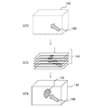
- FIG. 2 schematically shows a form of information acquired by the image processing apparatus 20 as a result of measurement by the sensor group 12.
- Each sensor included in the sensor group 12 acquires a distribution of a predetermined physical quantity with respect to a plurality of planes 19a, 19b,..., 19n perpendicular to a predetermined axis (z axis) as shown in FIG. It is assumed that the planes 19a, 19b,..., 19n are at different positions with respect to the z axis and in the same range with respect to the xy plane perpendicular thereto.
- the direction in which the plane for acquiring the physical quantity distribution by the sensor group 12 is moved as the z-axis in the figure is referred to as “sensor axis”, and the plane is referred to as “slice plane”.
- the sensor group 12 may be provided so that a plurality of sensor axes can be set.
- a plurality of slice plane groups are set for each sensor axis, and a physical quantity distribution is obtained for each plane.
- the slice plane is perpendicular to the sensor axis.
- the slice plane is not necessarily perpendicular depending on the physical quantity to be measured and the structure of the sensor.
- the “distribution” is obtained as a value for such a position coordinate on each slice plane
- the sensor group 12 includes N sensors 12_1, 12_2,..., 12_N as shown in FIG. N values for a certain position on the plane are obtained.
- the information acquired by the image processing apparatus 20 includes position coordinates (x, y) for each of a plurality of positions P1, P2,... Set for each slice plane 19a, 19b,.
- N-valued vector values (V_1, V_2,..., V_N) are associated with each other.
- the positions P1, P2,... May actually be set at intervals of about a general pixel, and depending on the resolution of the sensor, etc., the positions P1, P2,.
- Vector values of the same number of dimensions are obtained for P2,.
- the sensor group 12 may repeat measurement at predetermined time intervals, and the image processing apparatus 20 may acquire the information shown in FIG. 2 at each time.
- the finally displayed three-dimensional object is a moving image that changes over time.
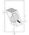
- FIG. 3 shows an example of an image generated by the image processing device 20 and displayed on the display device 14.
- Image example 4 is a visualization of the measurement information shown in FIG. 2, and is displayed in a state in which the object 16 is present inside the three-dimensional object 6 indicating the measurement space. Since the user can move the virtual viewpoint by rotating the input device 15 and rotate the three-dimensional object 6 to a desired angle, the user can check the back side and the side surface of the object.
- the transmittance of a desired area such as the area other than the object 16 and the area of the object 16 in the three-dimensional object 6 can be changed by a user operation to be transparent or translucent. Thereby, even when there are a plurality of objects, the positional relationship and size thereof can be observed from a desired direction.
- a region other than the target object of the three-dimensional object is displayed so as to be transparent, the three-dimensional object cannot be viewed, and only the target object can be viewed. In the following description, it is referred to as “three-dimensional object” including such a transparent region.
- the three-dimensional object 6 is a moving image, the movement of the target object and the generation of a new target object can be observed.
- an object different from the measurement result such as an arrow-shaped cursor 8 can be displayed in a state of entering the inside of the three-dimensional object 6.
- FIG. 4 shows the configuration of the image processing apparatus 20 in detail.
- each element described as a functional block for performing various processes can be configured by a CPU (Central Processing Unit), a GPU (Graphics Processing Unit), a memory, and other LSIs.
- CPU Central Processing Unit
- GPU Graphics Processing Unit
- memory and other LSIs.
- program for performing image processing it is realized by a program for performing image processing.
- the image processing apparatus 20 performs transmission / reception control of data with other apparatuses in the image processing system 10. However, since general techniques can be applied to such processing, illustration is omitted here. ing.
- the image processing apparatus 20 acquires output information from the sensor, generates an image data generation unit 30 that generates 2D image data used for display, and a display processing unit 32 that draws a 3D object using the 2D image data. including.
- an image data generation unit 30 that generates 2D image data used for display
- a display processing unit 32 that draws a 3D object using the 2D image data. including.
- the image data generation unit 30 is different from a sensor output data acquisition unit 42 that acquires output data from the sensor group 12, a slice image generation unit 44 that generates data of a two-dimensional image for each slice plane from which a distribution is acquired, and a sensor axis.
- An image axis conversion unit 50 that generates similar two-dimensional image data for a plurality of planes having a predetermined angle with the axis, a vector value information storage unit 46 that stores data generated by the sensor output data acquisition unit 42, and a slice image A slice image storage unit 48 that stores data generated by the generation unit 44 and the image axis conversion unit 50 is included.
- the sensor output data acquisition unit 42 acquires physical quantity distribution information for each slice plane from the sensor group 12, and generates vector value information in which position coordinates and vector values are associated as shown in FIG.
- the vector value information is temporarily stored in the vector value information storage unit 46 in association with the slice plane identification information, and the fact is notified to the slice image generation unit 44 and the image axis conversion unit 50.
- the identification information of the slice plane is constituted by the orientation of the sensor axis and the position on the sensor axis.
- the slice image generation unit 44 generates two-dimensional image data that is the basis of the three-dimensional object for each slice plane based on the vector value information stored in the vector value information storage unit 46.
- a two-dimensional image is referred to as a “slice image”.
- the slice image holds an alpha value representing the transmittance in addition to the color space information for each pixel.
- slice images are arranged in the sensor axis direction, and alpha blending drawing is performed so that the inside of the three-dimensional object can be seen through.
- the color space information and alpha value setting method will be described in detail later.
- the generated slice image data is stored in the slice image storage unit 48 in association with the slice plane identification information. There is also a method of calculating the alpha value from the pixel value of the slice image. In this case, if the alpha value is calculated in the drawing unit and used for blending, it is not necessary to store the alpha value in the slice image storage unit.
- the image axis conversion unit 50 has a predetermined angle with respect to each of an x axis and a y axis orthogonal to a predetermined axis different from the sensor axis, for example, when the z axis is a sensor axis as shown in FIG.
- a plurality of planes are generated, and vector value information similar to that shown in FIG. 2 is generated for each plane. That is, data is reconstructed as a distribution for the plane by picking up values corresponding to positions on planes with different orientations from physical values on the slice plane measured by the sensor group 12.
- two-dimensional image data corresponding to each plane is generated by the same processing as the slice image generation unit 44.
- this two-dimensional image is also referred to as a “slice image”, but the axis relative to the plane at this time is referred to as an “image axis” and is distinguished from a “sensor axis”.
- the slice image data generated by the image axis conversion unit 50 is also stored in the slice image storage unit 48 in association with the orientation of the image axis and the position on the axis.
- the display processing unit 32 additionally displays a slice image management unit 52 that manages slice images used for drawing according to the position of the viewpoint, a drawing memory 56 that sequentially stores image data necessary for drawing, a cursor, and the like.
- An additional object image storage unit 58 that stores object image data and an image drawing unit 54 that draws a three-dimensional object using slice image data are included.
- the slice image management unit 52 switches the axis of the slice image used for drawing by moving the viewpoint, and reads necessary slice image data from the slice image storage unit 48 to the drawing memory 56.
- the slice image storage unit 48 may also serve as the drawing memory 56.
- the drawing process is performed while loading the data gradually.
- the slice image management unit 52 further performs interpolation between slice images in accordance with a decrease in the distance between the viewpoint and the three-dimensional object.
- Slice images are generated at discrete positions on the sensor axis or the image axis, and when the viewpoint approaches the object, the discontinuity becomes easy to be visually recognized. Therefore, a new slice image having a pixel value for interpolating the pixel values of adjacent slice images with respect to the position on the axis is generated.
- the generated slice images are inserted between the original slice images, and the discontinuity is made inconspicuous by narrowing the interval between the slice images.
- the number of slice images to be inserted may be gradually increased so as to be inversely proportional to the distance to the viewpoint, or may be increased stepwise by comparing the distance with a threshold value.
- the image drawing unit 54 draws a notification that the necessary slice image data has been loaded into the drawing memory 56 from the slice image management unit 52, and draws a three-dimensional object using the data.
- each slice image is arranged at each position on the axis, and superposition is performed by sequentially projecting the slice image far from the viewpoint onto the screen coordinates.
- the three-dimensional object in the measurement space represented in this way becomes transparent or semi-transparent, for example, in a space without an object, depending on the setting of the alpha value. Therefore, the image drawing unit 54 further draws an additional object such as a cursor in such a space.
- the additional object can be moved by the user via the input device 15, or moved or generated following the target object. Therefore, the image drawing unit 54 calculates the display position of the additional object according to these modes, reads out the image data to the drawing memory 56, and draws it. Furthermore, the image drawing unit 54 may realize a stereoscopic view by performing the same three-dimensional object drawing process for a plurality of viewpoints. The relative position of the viewpoint in this case can be determined as appropriate according to the stereoscopic method to be introduced.
- FIG. 5 is a flowchart illustrating a processing procedure in which the image data generation unit 30 generates slice image data.
- the sensor output data acquisition unit 42 acquires, from the sensor group 12, distributions of N physical quantities for a plurality of slice planes of the sensor axis in accordance with a user instruction or the like via the input device 15, and positions on each plane.
- vector value information that associates a vector value composed of a set of physical quantities with each other (S10).
- the vector value included in the vector value information may not be the N physical quantities transmitted from the sensor group 12.
- unnecessary physical quantities may be excluded from the elements in view of the information to be displayed in the end, or values obtained as a result of operations performed on different physical quantities may be added as new elements of vector values.
- masking by threshold determination may be performed, for example, when a certain physical quantity exceeds a threshold value, another physical quantity is set to 0. For example, this method is effective when displaying only an object below a certain temperature.
- the slice image generation unit 44 determines an alpha value based on the vector value for each pixel of the two-dimensional array set on each slice plane (S12). A specific method for determining the alpha value will be described later. Furthermore, the slice image generation unit 44 determines color information for each pixel based on the vector value, thereby generating slice image data that holds the color information and the alpha value as the pixel value, and stores the data in the slice image storage unit 48. (S14).
- the color information color system such as RGB and YCbCr is not limited. Further, as described above, when the alpha value is generated from the slice image at the time of drawing in the image drawing unit 54, the slice image generating unit 44 does not need to set the alpha value, so the slice image storage unit 48 does not store the alpha value. .
- Color information is determined according to rules set in advance according to the type of physical quantity and display purpose.
- the values measured by the three sensors 12_1, 12_2, and 12_3 may be expressed as RGB as red luminance, green luminance, and blue luminance, respectively.
- the substance whose physical quantity measured by the sensor 12_1 increases is red
- the substance whose physical quantity measured by 12_2 increases is green
- the substance whose physical quantity measured by 12_3 increases is blue. Appears strongly and can be color-coded by substance.
- a single value measured by a certain sensor 12_1 may be substituted for all of R, G, and B, and the physical quantity may be represented by white luminance.
- the rules for determining the alpha value and the color information are appropriately determined by the user according to the display contents and display purpose, and stored in a memory (not shown). Alternatively, it may be set on the spot via the input device 15 while confirming the actual display.
- the processing in S12 and S14 is repeated until all slice images for the sensor axis are generated (N in S16, S12, S14).
- the image axis conversion unit 50 prepares a plurality of slice planes with respect to a predetermined image axis at positions where physical quantities are obtained, and a vector composed of a position on each plane and a set of physical quantities Vector value information in which values are associated is generated for each image axis (Y in S16, N in S18, S20, S10).
- the process of determining the alpha value and color information for the pixels set on each plane and generating and storing slice images is repeated until all slice images for each axis are generated (S12, S14, N of S16).
- slice images When all slice images have been generated for all image axes (Y in S18), the processing from S10 to S20 is repeated (N in S22) if the physical quantity can be acquired by another sensor axis. If slice images are generated for all sensor axes, the process is terminated (Y in S22). In order to suitably draw a three-dimensional object to be finally displayed in the present embodiment, it is desirable to prepare slice images for three axes. Most simply, slice images are generated with respect to the x-axis, y-axis, and z-axis that are orthogonal to each other. Any of these three axes may be used as the image axis, or the image axis may not be included.
- the image axis conversion unit 50 does not need to perform processing as long as the three axes in the direction can be measured as sensor axes.
- the image axis conversion unit 50 when the sensor axis is only in one direction, the image axis conversion unit 50 generates slice images for the other image axes, and the branch of S22 is eliminated.
- the image axis conversion unit 50 When the sensor axis is two directions, the image axis conversion unit 50 generates a slice image using the remaining one direction as an image axis. For example, the setting of the image axis is appropriately changed according to the direction that can be set as the sensor axis and the number thereof. Good.
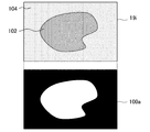
- FIG. 6 shows an example of a method for determining the alpha value of the slice image in S12 of FIG.
- the upper side of the drawing schematically represents vector value information in a certain slice plane 19i, and the lower side schematically represents an alpha value set in the corresponding slice image 100a.
- the slice plane 19i for example, at least one of the vector values greatly changes in the region 102 where the object exists and the other region 104.
- the difference is represented by two types of shading.
- Th is a predetermined threshold value
- A is an alpha value given to each pixel. That is, the alpha value is 0 if the maximum value of the vector values (V_1, V_2,..., V_N) is smaller than the threshold value Th, and the alpha value is 1 if it is greater than or equal to the threshold value Th.
- the region 102 has an alpha value of 1 and the region 104 has an alpha value of 0 in white and black, respectively.
- the position where the vector value is held in the slice plane of the vector value information may be different from the position where the pixel is defined in the slice image. In this case, the alpha value is determined at the former position and is interpolated accordingly. The value for each pixel is determined.
- conditional branching may be performed after a physical quantity to be subjected to branch determination is selected.
- a physical quantity that increases in the range of the object is included in the vector value and an alpha value is given by such conditional branching, the area without the object becomes transparent and the area with the object becomes opaque.
- ⁇ blending is drawn, only the area without the object can be viewed from the other side.
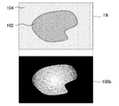
- FIG. 7 shows another example of a technique for determining the alpha value of a slice image.
- the way of representing the figure is the same as in FIG.
- the alpha value is 0 as in FIG. When this occurs, this maximum value itself is taken as the alpha value.
- each physical quantity constituting the vector value is normalized.
- the fact that the alpha value of the region 102 changes in the range of Th ⁇ A ⁇ 1 is represented by gradation.
- a change in physical quantity inside the object can be represented by a color transmittance.
- the alpha value near the contour of the object can be changed gently, so that even if jaggy or noise occurs in the contour, it is less noticeable.
- the alpha value can be changed according to the magnitude of the physical quantity constituting the vector value in an area where there is no object.
- the ambient temperature and ambient humidity of the object can be represented by color transmittance.
- conditional branches are the same as those shown in FIG. 6 and FIG. 7 except that one physical quantity V_i is subject to branch determination.
- one physical quantity V_i is subject to branch determination.
- the substance to be displayed as the object can be switched by switching the target physical quantity V_i.
- Th1 and Th2 may be provided, and the following conditional branch may be set. if max (V_1, V_2, ..., V_N) ⁇ Th2
- the vector value is predetermined.
- it falls within the intermediate range, it is made transparent with an alpha value of 0.
- the physical quantity acquired by one sensor is small and the physical quantity acquired by another sensor is large in the area of the target object, if either sensor reacts, they are all displayed as the target object. Applicable when you want to
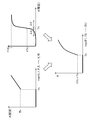
- FIG. 8 is a diagram for explaining a technique for suppressing the generation of such noise in setting the alpha value.
- the upper left graph shows the maximum value of vector values on the horizontal axis and the alpha value A determined by the conditional branch shown with reference to FIG. 7 on the vertical axis.
- the final alpha value A is determined by converting the alpha value determined in the conditional branch according to a predetermined rule. Therefore, the alpha value of the graph is a provisional value as shown in the figure.
- the provisional value of the alpha value A is zero.
- the provisional value of the alpha value A becomes the maximum value Th.
- a final alpha value A is calculated by applying a function f (A) as shown in the upper right of the figure.
- the function f (A) for example, rises gently from 0 at a provisional value of an alpha value that is smaller than the threshold Th by a predetermined width ⁇ A, and further 1 while the provisional value becomes larger than the threshold Th by a predetermined width ⁇ A. It is a function that reaches When the value obtained from such a function is multiplied by the provisional value of the alpha value A, a graph shown in the lower part of the figure is obtained.
- the alpha value A when the maximum vector value shown on the horizontal axis is smaller than the threshold value Th, the alpha value A is 0 like the provisional value.
- the alpha value A is kept smaller than the provisional value as a result of multiplying the provisional value Th by f (Th).
- the function f (A) is optimized according to the noise generation rate in the actual display image. Note that the alpha value A may be a value output by substituting the provisional value of the alpha value A into the function f.
- the previous alpha value setting method has been relatively simple based on conditional branching.
- an alpha value may be prepared in advance for the position coordinates in the N-dimensional space composed of N physical quantities constituting the vector value.
- the conditional branch may be complicated.
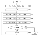
- FIG. 9 is a flowchart showing a processing procedure in which the display processing unit 32 performs display processing of a three-dimensional object.
- the slice image management unit 52 sets a predetermined viewpoint coordinate to display an initial image of the three-dimensional object as an initial viewpoint
- the slice image data necessary for drawing the three-dimensional object from the viewpoint is loaded into the drawing memory 56 (S32, S34).
- the drawing memory 56 S32, S34
- the slice image management unit 52 adjusts the amount of the slice image according to the distance between the viewpoint and the three-dimensional object (S36).
- a new slice image for interpolation is generated, it is stored in the drawing memory 56.
- the image data itself is inserted between the data of the preceding and succeeding slice images or is associated with the position on the axis so that the position of the insertion destination can be identified.
- the image drawing unit 54 draws an additional object to be displayed inside the three-dimensional object in response to an instruction input from the user via the input device 15 (S38).
- the additional object is a cursor that is moved by the user's operation, a marker that is displayed in contact with the object, a line that represents the trajectory of the object, and the like, which can be selected by the user.
- the image drawing unit 54 determines the position for displaying the additional object based on the designation by the user, the outline of the target obtained by the edge extraction process, and the like, and uses the image data loaded in the drawing memory 56 to use the additional object. Draw.
- the image drawing unit 54 draws a three-dimensional object representing the measurement space by superimposing the slice images loaded in the drawing memory 56 by alpha blending in order from the viewpoint (S40).
- the drawing process of the additional object in S38 may be performed simultaneously with the alpha blending drawing in S40.
- FIG. 10 schematically shows how the image drawing unit 54 performs alpha blending drawing in S40 of FIG. From the side closer to the viewpoint 114, the screen 116, slice images 110a, 110b,. At this time, the image projected on the point 115 on the screen 116 is an intersection 112a, 112b,... Of the line of sight 119 passing through the viewpoint 114 and the point 115 and the slice images 110a, 110b,. , 112n, 117 are superimposed from the viewpoint 114. In the case of the figure, the intersections 117, 112n,..., 112b, 112a are in this order.
- FIG. 11 is a flowchart showing a processing procedure for obtaining RGB values at the point 115 on the screen shown in FIG.
- variables Ri, Gi, Bi i is an integer equal to or greater than ⁇ 1
- the RGB values Rb, Gb, Bb at the intersection 117 of the background 118 are substituted for R ⁇ 1 , G ⁇ 1 , B ⁇ 1 , respectively.
- S50 When the RGB value and the alpha value of the intersection 112n on the slice image 110n farthest from the viewpoint are (R 0 , G 0 , B 0 , A 0 ), the intersection 117 of the background 118 and the intersection 112n on the slice image 110n are overlapped.
- the RGB values are as follows (S52, S54, S56, S58).
- Kr, Kg, and Kb are coefficients of alpha values for red, green, and blue, respectively, when the alpha value held in the slice image is adjusted by color, and in the range of 0 ⁇ K ⁇ 1, as necessary.
- R ′ k Kr ⁇ A k ⁇ R k + (1 ⁇ Kr ⁇ A k ) ⁇ R ′ k ⁇ 1
- G ′ k Kg ⁇ A k ⁇ G k + (1 ⁇ Kg ⁇ A k ) ⁇ G ′ k ⁇ 1
- B ′ k Kb ⁇ A k ⁇ B k + (1 ⁇ Kb ⁇ A k ) ⁇ B ′ k ⁇ 1 ...
- the RGB values after superposition are set as (R ′ k , G ′ k , B ′ k ), and are distinguished from the RGB values (R k , G k , B k ) of only the k + 1-th slice image.
- the final RGB value (R ' nslice-1 , G' nslice-1 , B ' nslice-1 ) can be expressed by a linear combination of RGB values for each slice image as follows.
- (Br i , Bg i , Bb i ) are coefficients of the RGB values (R i , G i , B i ) of the i + 1-th slice image, and are calculated from the alpha values of the slice image.
- a final factor used (Br i, Bg i, Bb i) Equation 3 in terms of the previously obtained according to the viewpoint RGB values may be calculated.
- FIG. 12 is a diagram for explaining processing in which the slice image management unit 52 determines necessary slice image data in accordance with the viewpoint in S34 of FIG.
- the slice image is an image of the distribution of physical quantities at discrete positions with respect to a predetermined axis.
- the slice image that is basically generated is a plurality of parallel planes that form the xy plane like the slice image group 120.
- a slice image is generated for an image axis different from the sensor axis, or a physical quantity is measured for a plurality of sensor axes to generate a slice image group for the plurality of axes.
- the slice image group used by movement is switched.
- a slice image group 122 having the x axis as the image axis and a slice image group 124 having the y axis as the image axis are prepared.
- the three-dimensional space around the three-dimensional object 126 to be displayed is divided, and the slice image group used for drawing is switched depending on in which division the viewpoint is located. For example, as indicated by the dotted lines in the figure, from each vertex of the three-dimensional object 126, a boundary line that makes a predetermined angle with the three sides of the three-dimensional object 126 forming the vertex is set. An approximately trapezoidal space having these boundary lines as side edges and each surface of the three-dimensional object as an upper surface is defined as one section.
- the slice image group 120 having the z axis as an axis is used for drawing.
- the slice image group 122 having the x axis as an axis is used for drawing.
- the slice image group 124 with the y axis as an axis is used for drawing.
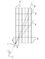
- FIG. 13 is a diagram for explaining an example of a method for determining the angle of the boundary line.
- the x-axis and the y-axis are axes.
- This figure shows a state in which a slice image group 122 (dotted line) with the x axis as an axis and a slice image group 124 (solid line) with the y axis as an axis are arranged on the same xy plane and viewed from the z-axis direction.
- the line of sight passing through the vertex v changes as indicated by arrows 128, 129, and 130 depending on the position of the viewpoint.
- the number of slice image groups having an intersection with each line of sight is as follows in the order of the slice image group 122 having the x axis as the axis and the slice image group 124 having the y axis as the axis.
- Line of sight of arrow 128 4/6 sheets
- Line of sight of arrow 129 6/6 sheets
- Line of sight of arrow 130 7/6 sheets
- the same display image is obtained because the same number of alpha blending processes are performed regardless of which slice image group data is used. Therefore, the display image before and after switching is continuously connected by setting the direction of the arrow 129 as a boundary line.
- the angle ⁇ of the arrow 129 is
- Wy / Wx. In order to satisfy, the slice image group is switched under the following conditions.
- the line-of-sight vector serving as the boundary of the above conditions corresponds to the boundary line indicated by the dotted line in FIG.
- the sensor axis or the image axis is perpendicular to the slice image.
- the present embodiment is not limited thereto.
- the slice image generated by the image axis conversion unit 50 by reconstructing the measurement value may not be perpendicular to the image axis.
- the sensor axis and the image axis may not be orthogonal.
- the boundary line can be set based on the same theory as described above, and the slice image switching and the alpha blending drawing process according to the viewpoint are the same.
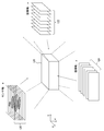
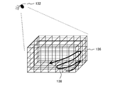
- FIG. 14 is a diagram for explaining another method of drawing a three-dimensional object.
- slice image groups for the x-axis, y-axis, and z-axis are simultaneously used as texture images in three directions.
- a general computer graphics drawing process can be applied to the method of drawing the three-dimensional object 136 with the texture pasted on each surface in accordance with the position of the viewpoint 132.
- the slice image in each direction has an alpha channel as described above, superposition from pixels far from the viewpoint 132 is necessary.
- the three-dimensional object 136 is divided into a lattice shape by a slice image group in three directions.
- straight lines intersecting each other represented in the three-dimensional object 136 represent the edge of each slice image. If the target is a three-dimensional array of small rectangular parallelepipeds obtained by such division, the order far from the viewpoint 132 can be easily specified.
- the three-dimensional object 136 can be expressed in a transparent and translucent state by superimposing it on the screen using the pixel values of slice images constituting the surfaces of the rectangular parallelepipeds in the order of the arrows 138.
- the slice image management unit 52 loads data of slice image groups in three directions regardless of the position of the viewpoint.
- FIG. 15 schematically shows a processing procedure for drawing a three-dimensional object after drawing an additional object first as one method.
- a virtual rectangular parallelepiped 142 in which a three-dimensional object is finally drawn is prepared according to the position of the viewpoint, and the additional object 140 is drawn at a required position inside the rectangular parallelepiped 142 by a general method (S70). .
- the additional object 140 is an arrow-shaped cursor figure.
- a three-dimensional object is drawn using the slice image by the above method (S72). By drawing the additional object 140 first, the additional object 140 remains as it is in an area where the alpha value is close to 0 and the transmittance is high.
- the state where the cursor is floated as the additional object 140 in the three-dimensional object 146 can be drawn (S74).
- a presentation using display can be suitably performed.
- the moving object is displayed as a moving image with time, the locus of the object may be displayed.
- another target product
- the calculation of the position of the product may be performed separately, and the user may input as an input value.
- FIG. 16 schematically shows a processing procedure of another method for drawing an additional object.
- the drawing of the three-dimensional object using the slice image and the drawing of the additional object are advanced in parallel.
- alpha blending drawing using a slice image is advanced to a position where an additional object is drawn (S80).
- the additional object portion 152a that should be in the space from the uppermost slice image 150a to the next slice image is drawn (S82).
- the slice image 150b positioned next to the slice image 150a is overlaid (S84). Then, the additional object portion 152b that should be in the space from the slice image 150b to the next slice image is drawn (S86). In the case of the figure, the entire additional object is drawn at this stage. After that, by superimposing the remaining slice images, the state where the cursor is floated as the additional object 140 in the three-dimensional object 146 can be drawn as in FIG. 15 (S88).
- FIG. 17 schematically shows a procedure for reading slice image data when the sensor group 12 displays the measurement result at a predetermined rate as a moving image of a three-dimensional object.
- a slice image group in three directions is generated for each time, but the illustration is omitted here.
- the slice image management unit 52 loads the slice images necessary for drawing into the drawing memory 56 in order. For example, a slice image farthest from the viewpoint position is specified, and the slice image data is loaded in order. At this time, a load unit composed of a plurality of slice images may be formed according to the bandwidth of the bus serving as a transfer path, and the load may be loaded in the load unit. In the example of the figure, data of three slice images indicated by thick frames are loaded simultaneously as a load unit.
- the image drawing unit 54 sequentially reads the slice image data from the drawing memory 56 and executes alpha blending drawing.
- the slice image management unit 52 loads the subsequent slice image data in units of load.
- a slice image having an alpha channel is created from layered image information obtained by acquiring cross-sectional information of an object on a plurality of parallel planes, and alpha blending is performed, so that the measurement space is 3 Expressed as a dimensional object.
- the alpha value and color information decision rules can be changed variously, so that the user who creates the image can easily perform processing suitable for the display contents and display purpose.
- the first layer image information acquired is for one axis
- slice images for a plurality of axes are generated in advance, and the slice image to be used is switched according to the position of the viewpoint when displaying a three-dimensional object.
- the amount of slice images is adjusted according to the proximity of the viewpoint.
- a transparent and translucent space can be generated in the 3D object, additional objects such as a cursor can be displayed in the 3D object.
- additional objects such as a cursor can be displayed in the 3D object.
- the order of slice images to be used can be determined according to the position of the viewpoint. Therefore, if data is loaded from the secondary storage device to the memory in that order, the loading process and the drawing process are performed. Can be parallel. Thereby, the latency to display can be suppressed even in a situation where the loading frequency of the slice image data is increased by moving the viewpoint or making the three-dimensional object a moving image. As a result, a smooth display change can be realized without increasing the memory capacity.
- the slice plane of the present embodiment is a plane having a predetermined angle with the sensor axis or the image axis, but is not limited to a plane and may be a curved surface such as a spherical surface or a curved surface with fluctuations.
- FIG. 18 schematically shows the shape of a slice image when measuring a distribution with respect to a partially cylindrical curved surface or a partially spherical surface.
- the sensor group 208 measures the measurement space in which the object 216 exists, and the distribution of the measured values at this time has a sensor axis on the z-axis in the vertical direction in the figure and a plurality of parallel lines centering on the sensor axis.
- the curved surfaces 210a, 210b,..., 210n are indicated by fan-shaped curves in a cross section passing through the sensor axis.
- the slice image generation unit 44 For the slice curved surfaces 210a, 210b,..., 210n, the slice image generation unit 44 generates a slice image as described in the embodiment.
- the curved surface is the same as the curved surface.
- the image axis conversion unit 50 prepares a plurality of planes or curved surfaces that cross the slice curved surfaces 210a, 210b,..., 210n at a predetermined angle, and extracts the measured values on the surfaces to extract the slice curved surfaces 210a, 210b, ..., a slice image group having a different direction from 210n is generated.
- slice image groups are generated for planes 212a, 212b,..., 212n perpendicular to the drawing that cross the slice curved surfaces 210a, 210b,. Furthermore, a slice image group arranged in the depth direction in the figure is also generated.
- the drawing is performed in the same order as shown in FIG. 14 for each small solid divided by the slice image group in each direction.
- a three-dimensional object can be drawn by a general computer graphics technique by treating an image as a texture regardless of the shape of the slice image. Therefore, the measurement result can be visualized similarly and easily if the shape and the intersecting angle are known.
- the present invention can be used for information processing apparatuses such as computers, image processing apparatuses, and measurement apparatuses.
Landscapes
- Engineering & Computer Science (AREA)
- Physics & Mathematics (AREA)
- Health & Medical Sciences (AREA)
- Life Sciences & Earth Sciences (AREA)
- General Physics & Mathematics (AREA)
- Theoretical Computer Science (AREA)
- Computer Graphics (AREA)
- Public Health (AREA)
- Veterinary Medicine (AREA)
- Molecular Biology (AREA)
- Surgery (AREA)
- Animal Behavior & Ethology (AREA)
- General Health & Medical Sciences (AREA)
- Pathology (AREA)
- Medical Informatics (AREA)
- Biophysics (AREA)
- Heart & Thoracic Surgery (AREA)
- Biomedical Technology (AREA)
- Geometry (AREA)
- Image Processing (AREA)
- Processing Or Creating Images (AREA)
- Image Generation (AREA)
- Measuring And Recording Apparatus For Diagnosis (AREA)
Abstract
Selon l'invention, une unité d'acquisition de données de sortie de capteur (42) d'une unité de génération de données d'image (30) dans un dispositif de traitement d'image (20) acquiert des données d'informations d'image en couches à partir d'un groupe de capteurs (12). Une unité de génération d'image de tranche (44) génère des données d'image bidimensionnelle pour chaque plan de tranche pour lequel une distribution a été acquise. Une unité de transformation d'axe d'image (50) génère le même type de données d'image bidimensionnelle pour de multiples plans perpendiculaires à un axe différent d'un axe de capteur. Conformément à des propriétés, telles qu'une position de visualisation, une unité de gestion d'image de tranche (52) d'une unité de traitement d'affichage (32) gère des images de tranche à utiliser pour une représentation. Une unité de mémoire de représentation (56) stocke successivement les données d'image nécessaires pour une représentation. Une unité de stockage d'image d'objet supplémentaire (58) stocke des données d'image pour un objet à afficher en plus, tel qu'un curseur. Une unité de représentation d'image (54) représente un objet tridimensionnel à l'aide des données pour les images de tranche.
Priority Applications (3)
| Application Number | Priority Date | Filing Date | Title |
|---|---|---|---|
| CN201280054856.6A CN103918013B (zh) | 2011-11-10 | 2012-10-23 | 图像处理装置、图像处理方法、及图像文件的数据结构 |
| EP12847428.5A EP2779109B1 (fr) | 2011-11-10 | 2012-10-23 | Dispositif de traitement d'image, procédé de traitement d'image et structure de données de fichier d'image |
| US14/356,753 US9466146B2 (en) | 2011-11-10 | 2012-10-23 | Image processing apparatus, image processing method and data structure of image file |
Applications Claiming Priority (2)
| Application Number | Priority Date | Filing Date | Title |
|---|---|---|---|
| JP2011246279A JP5866177B2 (ja) | 2011-11-10 | 2011-11-10 | 画像処理装置および画像処理方法 |
| JP2011-246279 | 2011-11-10 |
Publications (1)
| Publication Number | Publication Date |
|---|---|
| WO2013069215A1 true WO2013069215A1 (fr) | 2013-05-16 |
Family
ID=48289080
Family Applications (1)
| Application Number | Title | Priority Date | Filing Date |
|---|---|---|---|
| PCT/JP2012/006767 WO2013069215A1 (fr) | 2011-11-10 | 2012-10-23 | Dispositif de traitement d'image, procédé de traitement d'image et structure de données de fichier d'image |
Country Status (5)
| Country | Link |
|---|---|
| US (1) | US9466146B2 (fr) |
| EP (1) | EP2779109B1 (fr) |
| JP (1) | JP5866177B2 (fr) |
| CN (1) | CN103918013B (fr) |
| WO (1) | WO2013069215A1 (fr) |
Cited By (1)
| Publication number | Priority date | Publication date | Assignee | Title |
|---|---|---|---|---|
| WO2016166858A1 (fr) * | 2015-04-15 | 2016-10-20 | オリンパス株式会社 | Système d'observation au microscope, procédé d'observation au microscope, et programme d'observation au microscope |
Families Citing this family (14)
| Publication number | Priority date | Publication date | Assignee | Title |
|---|---|---|---|---|
| US9132352B1 (en) | 2010-06-24 | 2015-09-15 | Gregory S. Rabin | Interactive system and method for rendering an object |
| US9754169B2 (en) * | 2011-12-16 | 2017-09-05 | Nec Corporation | Information processing system, information processing method, information processing device and control method and control program thereof, and communication terminal and control method and control program thereof |
| JP5988088B2 (ja) * | 2012-06-08 | 2016-09-07 | 富士通株式会社 | 描画プログラム、描画方法、および、描画装置 |
| KR20150033162A (ko) * | 2013-09-23 | 2015-04-01 | 삼성전자주식회사 | 컴포지터, 이를 포함하는 시스템온칩 및 이의 구동 방법 |
| JP5665068B1 (ja) * | 2014-09-05 | 2015-02-04 | 株式会社Live2D | プログラム、情報処理装置、制御方法及び記録媒体 |
| JP6738631B2 (ja) * | 2016-03-29 | 2020-08-12 | ザイオソフト株式会社 | 医用画像処理装置、医用画像処理方法、及び医用画像処理プログラム |
| CN106127862B (zh) * | 2016-06-16 | 2019-02-26 | 财付通支付科技有限公司 | 图形的处理方法和装置 |
| CN106210693A (zh) * | 2016-06-29 | 2016-12-07 | 联想(北京)有限公司 | 一种图像显示的方法、电子设备及电子装置 |
| KR101947692B1 (ko) * | 2017-06-23 | 2019-04-29 | 주식회사 맥스로텍 | 3d 모델 슬라이싱 장치 및 방법 |
| US20200388032A1 (en) * | 2019-06-04 | 2020-12-10 | JelloX Biotech Inc. | Three dimensional histopathology imaging method and system thereof |
| CN110505465B (zh) | 2019-08-30 | 2022-08-23 | 京东方科技集团股份有限公司 | 数据传输方法、三维图像显示方法、装置及电子设备 |
| EP4042378A1 (fr) * | 2020-01-24 | 2022-08-17 | St. Jude Medical, Cardiology Division, Inc. | Système et procédé permettant de générer des modèles géométriques tridimensionnels de régions anatomiques |
| CN114489315B (zh) * | 2020-11-12 | 2023-12-19 | 幻景启动股份有限公司 | 图像处理系统以及图像处理装置 |
| KR102353500B1 (ko) * | 2020-11-25 | 2022-01-20 | 한국전자기술연구원 | 공차 오류 문제를 해결하기 위한 3d 프린팅 슬라이싱 방법 |
Citations (2)
| Publication number | Priority date | Publication date | Assignee | Title |
|---|---|---|---|---|
| JPH05266215A (ja) * | 1992-03-18 | 1993-10-15 | Toshiba Corp | 画像表示装置 |
| JP2003263651A (ja) * | 2002-03-12 | 2003-09-19 | Inst Of Physical & Chemical Res | ボリュームレンダリング方法とそのプログラム |
Family Cites Families (10)
| Publication number | Priority date | Publication date | Assignee | Title |
|---|---|---|---|---|
| US6297799B1 (en) * | 1998-11-12 | 2001-10-02 | James Knittel | Three-dimensional cursor for a real-time volume rendering system |
| AU2001239926A1 (en) * | 2000-02-25 | 2001-09-03 | The Research Foundation Of State University Of New York | Apparatus and method for volume processing and rendering |
| JP3529759B2 (ja) * | 2001-01-26 | 2004-05-24 | 株式会社ソニー・コンピュータエンタテインメント | 画像処理プログラム、画像処理プログラムを記録したコンピュータ読み取り可能な記録媒体、プログラム実行装置、画像処理装置、及び画像処理方法 |
| US7043701B2 (en) * | 2002-01-07 | 2006-05-09 | Xerox Corporation | Opacity desktop with depth perception |
| JP2004141514A (ja) * | 2002-10-28 | 2004-05-20 | Toshiba Corp | 画像処理装置及び超音波診断装置 |
| JP3960382B2 (ja) * | 2003-06-18 | 2007-08-15 | 独立行政法人産業技術総合研究所 | テンソルボリュームデータの実時間可視化方法及び装置 |
| US7154500B2 (en) | 2004-04-20 | 2006-12-26 | The Chinese University Of Hong Kong | Block-based fragment filtration with feasible multi-GPU acceleration for real-time volume rendering on conventional personal computer |
| US8330763B2 (en) * | 2007-11-28 | 2012-12-11 | Siemens Aktiengesellschaft | Apparatus and method for volume rendering on multiple graphics processing units (GPUs) |
| US8044971B2 (en) * | 2008-01-31 | 2011-10-25 | Arm Norway As | Methods of and apparatus for processing computer graphics |
| DE102009042327A1 (de) * | 2009-09-21 | 2011-04-07 | Siemens Aktiengesellschaft | Effiziente Visualisierung von Objekteigenschaften mittels Volume Rendering |
-
2011
- 2011-11-10 JP JP2011246279A patent/JP5866177B2/ja active Active
-
2012
- 2012-10-23 WO PCT/JP2012/006767 patent/WO2013069215A1/fr active Application Filing
- 2012-10-23 EP EP12847428.5A patent/EP2779109B1/fr active Active
- 2012-10-23 CN CN201280054856.6A patent/CN103918013B/zh active Active
- 2012-10-23 US US14/356,753 patent/US9466146B2/en active Active
Patent Citations (2)
| Publication number | Priority date | Publication date | Assignee | Title |
|---|---|---|---|---|
| JPH05266215A (ja) * | 1992-03-18 | 1993-10-15 | Toshiba Corp | 画像表示装置 |
| JP2003263651A (ja) * | 2002-03-12 | 2003-09-19 | Inst Of Physical & Chemical Res | ボリュームレンダリング方法とそのプログラム |
Non-Patent Citations (2)
| Title |
|---|
| KOICHI MATSUDA ET AL.: "Interactive Arbitrary Cross-Section Visualization Using 2D-Texture on Standard PC", THE TRANSACTIONS OF THE INSTITUTE OF ELECTRONICS, INFORMATION AND COMMUNICATION ENGINEERS(J85-D-II), 1 August 2002 (2002-08-01), pages 1351 - 1354, XP008173547 * |
| See also references of EP2779109A4 * |
Cited By (2)
| Publication number | Priority date | Publication date | Assignee | Title |
|---|---|---|---|---|
| WO2016166858A1 (fr) * | 2015-04-15 | 2016-10-20 | オリンパス株式会社 | Système d'observation au microscope, procédé d'observation au microscope, et programme d'observation au microscope |
| US10429632B2 (en) | 2015-04-15 | 2019-10-01 | Olympus Corporation | Microscopy system, microscopy method, and computer-readable recording medium |
Also Published As
| Publication number | Publication date |
|---|---|
| JP2013105188A (ja) | 2013-05-30 |
| EP2779109A1 (fr) | 2014-09-17 |
| EP2779109B1 (fr) | 2020-04-22 |
| EP2779109A4 (fr) | 2016-06-01 |
| JP5866177B2 (ja) | 2016-02-17 |
| US9466146B2 (en) | 2016-10-11 |
| US20140306952A1 (en) | 2014-10-16 |
| CN103918013A (zh) | 2014-07-09 |
| CN103918013B (zh) | 2017-10-20 |
Similar Documents
| Publication | Publication Date | Title |
|---|---|---|
| JP5866177B2 (ja) | 画像処理装置および画像処理方法 | |
| JP6563048B2 (ja) | スクリーンの位置によって異なる解像度のターゲットの複数レンダリングのテクスチャ・マッピングの傾き調整 | |
| CN112513712B (zh) | 具有虚拟内容翘曲的混合现实系统和使用该系统生成虚拟内容的方法 | |
| CN104794758B (zh) | 一种三维图像的裁剪方法 | |
| JP6359868B2 (ja) | 3次元データ表示装置、3次元データ表示方法、及び3次元データ表示プログラム | |
| EP2831848B1 (fr) | Procédé d'estimation du niveau d'opacité dans une scène et dispositif correspondant | |
| KR20160130433A (ko) | 가변 렌더링 및 래스터화 파라미터 하에서 가변 뷰포트에 대하여 오브젝트를 효율적으로 리렌더링하는 방법 | |
| US10217259B2 (en) | Method of and apparatus for graphics processing | |
| JP4885042B2 (ja) | 画像処理方法および装置ならびにプログラム | |
| CN110458959B (zh) | 体三维显示仿真方法、装置、设备及计算机可读存储介质 | |
| JP7038683B2 (ja) | 合成装置、方法及びプログラム | |
| JP2012190428A (ja) | 立体映像視覚効果処理方法 | |
| US9401044B1 (en) | Method for conformal visualization | |
| JP6719596B2 (ja) | 画像生成装置、及び画像表示制御装置 | |
| US11120614B2 (en) | Image generation apparatus and image generation method | |
| US8203553B2 (en) | Distributed calculation of images of volumetric objects | |
| JP6106293B2 (ja) | 画像処理装置、画像処理システム、および画像処理方法 | |
| KR101227155B1 (ko) | 저해상도 그래픽 영상을 고해상도 그래픽 영상으로 실시간 변환하는 그래픽 영상 처리 장치 및 방법 | |
| JP2008259698A (ja) | 画像処理方法および装置並びにプログラム | |
| Dong et al. | Resolving incorrect visual occlusion in outdoor augmented reality using TOF camera and OpenGL frame buffer | |
| US6856325B2 (en) | Information processing method and apparatus | |
| US20140320494A1 (en) | Image processing apparatus, image processing method, computer readable non-transitory recording medium and image processing system | |
| JP7455546B2 (ja) | 画像処理装置、画像処理方法、及びプログラム | |
| US10453247B1 (en) | Vertex shift for rendering 360 stereoscopic content | |
| US20230351674A1 (en) | Image processing device and image processing method |
Legal Events
| Date | Code | Title | Description |
|---|---|---|---|
| 121 | Ep: the epo has been informed by wipo that ep was designated in this application |
Ref document number: 12847428 Country of ref document: EP Kind code of ref document: A1 |
|
| WWE | Wipo information: entry into national phase |
Ref document number: 14356753 Country of ref document: US |
|
| NENP | Non-entry into the national phase |
Ref country code: DE |
|
| WWE | Wipo information: entry into national phase |
Ref document number: 2012847428 Country of ref document: EP |