WO2013065503A1 - Liquid atomization device - Google Patents
Liquid atomization device Download PDFInfo
- Publication number
- WO2013065503A1 WO2013065503A1 PCT/JP2012/077075 JP2012077075W WO2013065503A1 WO 2013065503 A1 WO2013065503 A1 WO 2013065503A1 JP 2012077075 W JP2012077075 W JP 2012077075W WO 2013065503 A1 WO2013065503 A1 WO 2013065503A1
- Authority
- WO
- WIPO (PCT)
- Prior art keywords
- liquid
- gas
- gas injection
- angle
- unit
- Prior art date
Links
Images


Classifications
-
- B—PERFORMING OPERATIONS; TRANSPORTING
- B01—PHYSICAL OR CHEMICAL PROCESSES OR APPARATUS IN GENERAL
- B01F—MIXING, e.g. DISSOLVING, EMULSIFYING OR DISPERSING
- B01F23/00—Mixing according to the phases to be mixed, e.g. dispersing or emulsifying
- B01F23/20—Mixing gases with liquids
- B01F23/21—Mixing gases with liquids by introducing liquids into gaseous media
- B01F23/213—Mixing gases with liquids by introducing liquids into gaseous media by spraying or atomising of the liquids
- B01F23/2132—Mixing gases with liquids by introducing liquids into gaseous media by spraying or atomising of the liquids using nozzles
- B01F23/21322—Internal mixer atomization, i.e. liquid and gas are mixed and atomized in a jet nozzle before spraying
-
- B—PERFORMING OPERATIONS; TRANSPORTING
- B05—SPRAYING OR ATOMISING IN GENERAL; APPLYING FLUENT MATERIALS TO SURFACES, IN GENERAL
- B05B—SPRAYING APPARATUS; ATOMISING APPARATUS; NOZZLES
- B05B1/00—Nozzles, spray heads or other outlets, with or without auxiliary devices such as valves, heating means
- B05B1/26—Nozzles, spray heads or other outlets, with or without auxiliary devices such as valves, heating means with means for mechanically breaking-up or deflecting the jet after discharge, e.g. with fixed deflectors; Breaking-up the discharged liquid or other fluent material by impinging jets
-
- B—PERFORMING OPERATIONS; TRANSPORTING
- B01—PHYSICAL OR CHEMICAL PROCESSES OR APPARATUS IN GENERAL
- B01F—MIXING, e.g. DISSOLVING, EMULSIFYING OR DISPERSING
- B01F25/00—Flow mixers; Mixers for falling materials, e.g. solid particles
- B01F25/30—Injector mixers
-
- B—PERFORMING OPERATIONS; TRANSPORTING
- B05—SPRAYING OR ATOMISING IN GENERAL; APPLYING FLUENT MATERIALS TO SURFACES, IN GENERAL
- B05B—SPRAYING APPARATUS; ATOMISING APPARATUS; NOZZLES
- B05B7/00—Spraying apparatus for discharge of liquids or other fluent materials from two or more sources, e.g. of liquid and air, of powder and gas
- B05B7/0012—Apparatus for achieving spraying before discharge from the apparatus
-
- B—PERFORMING OPERATIONS; TRANSPORTING
- B05—SPRAYING OR ATOMISING IN GENERAL; APPLYING FLUENT MATERIALS TO SURFACES, IN GENERAL
- B05B—SPRAYING APPARATUS; ATOMISING APPARATUS; NOZZLES
- B05B7/00—Spraying apparatus for discharge of liquids or other fluent materials from two or more sources, e.g. of liquid and air, of powder and gas
- B05B7/02—Spray pistols; Apparatus for discharge
- B05B7/04—Spray pistols; Apparatus for discharge with arrangements for mixing liquids or other fluent materials before discharge
- B05B7/0416—Spray pistols; Apparatus for discharge with arrangements for mixing liquids or other fluent materials before discharge with arrangements for mixing one gas and one liquid
- B05B7/0483—Spray pistols; Apparatus for discharge with arrangements for mixing liquids or other fluent materials before discharge with arrangements for mixing one gas and one liquid with gas and liquid jets intersecting in the mixing chamber
-
- B—PERFORMING OPERATIONS; TRANSPORTING
- B05—SPRAYING OR ATOMISING IN GENERAL; APPLYING FLUENT MATERIALS TO SURFACES, IN GENERAL
- B05B—SPRAYING APPARATUS; ATOMISING APPARATUS; NOZZLES
- B05B7/00—Spraying apparatus for discharge of liquids or other fluent materials from two or more sources, e.g. of liquid and air, of powder and gas
- B05B7/02—Spray pistols; Apparatus for discharge
- B05B7/08—Spray pistols; Apparatus for discharge with separate outlet orifices, e.g. to form parallel jets, i.e. the axis of the jets being parallel, to form intersecting jets, i.e. the axis of the jets converging but not necessarily intersecting at a point
- B05B7/0807—Spray pistols; Apparatus for discharge with separate outlet orifices, e.g. to form parallel jets, i.e. the axis of the jets being parallel, to form intersecting jets, i.e. the axis of the jets converging but not necessarily intersecting at a point to form intersecting jets
- B05B7/0861—Spray pistols; Apparatus for discharge with separate outlet orifices, e.g. to form parallel jets, i.e. the axis of the jets being parallel, to form intersecting jets, i.e. the axis of the jets converging but not necessarily intersecting at a point to form intersecting jets with one single jet constituted by a liquid or a mixture containing a liquid and several gas jets
Definitions
- the present invention relates to a liquid atomizing apparatus for atomizing a liquid.
- Conventional atomization techniques include gas-liquid mixing type (two-fluid type), ultrasonic type, ultra-high pressure type (100 MPa to 300 MPa), and evaporation type.
- a general two-fluid nozzle injects gas and a liquid in the same injection direction, and refines
- a spray nozzle device for generating fine particle mist is known (Patent Document 1).
- This spray nozzle device has a first nozzle part and a second nozzle part, and can collide the spray liquid from the first nozzle part with the spray liquid from the second nozzle part to form a fine particle mist.
- the cost is high, and it is not suitable for downsizing.
- the spray angle is a wide angle (for example, 80 ° or more)
- the spray flow adheres to the spray outlet portion and drops and drops, so that the surroundings are wetted, which is a problem. It was.
- An object of the present invention is to provide a liquid atomizing apparatus capable of atomizing a liquid using a principle different from the above-described prior art miniaturization principle and with a simple apparatus configuration.
- the liquid atomization apparatus of the present invention includes a first gas injection unit and a second gas injection unit for causing two gas flows to collide with each other, A liquid outflow part for flowing out the liquid;
- the gas-liquid is an area in which the gas flow injected from the first gas injection unit, the gas flow injected from the second gas injection unit, and the liquid flowing out from the liquid outflow unit collide with each other to atomize the liquid.
- a mixing area A projecting portion that is formed so as to protrude in a cross-sectional convex shape on the outside of the device, and in which the gas-liquid mixing area portion is formed;
- the ejection slit portion formed along the wide-angle spray direction of the mist generated in the gas-liquid mixing area portion on the protruding portion,
- a restricting portion formed to be inclined toward the wide-angle spray direction of the mist in the vicinity of the bottom of the ejection slit portion.
- FIGS. 1A to 1C Schematic cross-sectional views of the atomization area.
- a portion including the collision portion 100 is referred to as a collision wall (FIG. 1B).
- the liquid 61 that has flowed out from the liquid outflow portion 6 collides with the collision wall (including the collision portion 100) (FIG. 1B).
- the liquid 61 collides with the collision wall, the liquid 61 is crushed (atomized) to become a mist 62.
- An area where the mist 62 is generated is indicated by a broken line as the gas-liquid mixing area 120.
- the mist 62 is spread over a wide angle (spread in a fan shape) from the gap between the ejection slits 31 formed in the protrusion 30 (see FIGS. 2A and 2B).
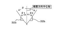
- restricting portions 32a and 32b are formed in the vicinity of the bottom of the ejection slit portion 31 toward the wide-angle spray direction of the mist (FIG. 1C).
- the restricting portions 32a and 32b make it easy for the sprayed mist to be ejected forward without adhering to the nozzle tip surface, making it difficult for the tip of the nozzle to drop even with wide angle spraying, and the average particle size in the major axis direction of the spray pattern. It becomes almost equal.
- the restriction portions 32a and 32b may be formed such that the tip end portion or the inclined surface thereof protrudes outside (spraying direction) the end portion of the groove section of the ejection slit portion 31. Further, the restricting portions 32a and 32b may be formed outside (spraying direction) the inside of the recessed groove (or the protruding portion 30) of the ejection slit portion 31.
- the protrusion may be formed integrally with a member for forming the gas orifice, or may be formed of a separate member.
- a low pressure low gas pressure, low liquid pressure.
- Low flow rate low gas flow rate, low liquid flow rate
- the liquid atomization apparatus of the present invention has low noise.
- the structure of the liquid atomization apparatus of this invention can be simplified.
- the liquid can be suitably atomized with a low gas pressure and a low gas flow rate according to the atomization principle of the present invention.
- the cross-sectional shape of the gas flow injected from the gas injection unit is not particularly limited, and examples thereof include a circular shape, an elliptical shape, a rectangular shape, and a polygonal shape.
- the cross-sectional shape of the gas flow which comprises a collision part and a collision wall is the same or substantially the same.
- the pressure and flow rate of the liquid (liquid flow) flowing out from the liquid outflow portion are not particularly limited, the low pressure and low flow rate liquid can be suitably atomized by the atomization principle of the present invention.
- the pressure of the liquid outflow portion may be generally the water pressure of a water pipe, and the liquid outflow portion may be a device that naturally drops the liquid.
- the “liquid that has flowed out from the liquid outflow portion” includes liquid that falls at a natural falling speed.
- FIG. 3A A relative arrangement example of the liquid outflow portion and the gas injection portion will be described with reference to FIGS. 3A to 3F.
- This relative arrangement defines the gas-liquid collision position.
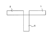
- the first and second gas injection units 1 and 2 are opposed to each other, and the nozzle tip of the liquid outflow unit 6 contacts the outer surface of both nozzle tips of the first and second gas injection units 1 and 2. is doing.
- the first and second gas injection units 1 and 2 face each other, and both the nozzle tips of the first and second gas injection units 1 and 2 and the nozzle tip of the liquid outflow unit 6 are in contact with each other. ing.
- FIG. 3B the arrangement of FIG.
- FIG. 3B tends to have a larger liquid flow rate and a smaller backflow than the arrangement of FIG. 3A.
- the arrangement in FIG. 3C is an arrangement in which the nozzle of the liquid outflow portion 6 enters between the nozzle tips of the first and second gas injection units 1 and 2.
- the arrangement of FIG. 3D is an arrangement in which the distance between the nozzles of the first and second gas injection units 1 and 2 is larger than that of FIG. 3B as compared to the arrangement of FIG. 3B.
- the arrangement of FIG. 3E is an arrangement in which the liquid outflow portion 6 is moved away from the collision wall as compared with the arrangement of FIG. 3B.
- one liquid outflow part is illustrated, two or more liquid outflow parts may be sufficient, and in FIG. 3F, two liquid outflow parts are arrange
- other members such as protrusions are omitted.
- the generated mist is sprayed together with the exhaust gas flow discharged from the collision part of the gas flows.
- This exhaust gas flow forms a spray pattern.
- the spray pattern for example, when a collision part formed by collision of two jetted gas flows and a liquid (liquid flow) collide, the liquid outflow direction axis is set in the opening direction of the ejection slit part 31. It is formed in a fan shape that is wide at the center, and its cross-sectional shape is elliptical or elliptical (FIGS. 2A and 2B).
- the gas that has collided (after the collision) is diffused, and the mist 62 spreads in a fan shape and is ejected in this direction.
- the wide-angle spray angle ⁇ of the mist 62 is 80 ° or more, and a wide-angle spray angle of 100 ° to 180 ° is also possible.
- an intersection angle between an injection direction axis of the first gas injection unit and an injection direction axis of the second gas injection unit is in a range of 90 ° to 180 °.
- the angle ranges in which the respective injection direction axes of the first gas injection unit 1 and the second gas injection unit 2 intersect are the gas injected from the first gas injection unit 1 and the gas injected from the second gas injection unit 2.
- the collision angle ⁇ is 90 ° to 220 °, preferably 90 ° to 180 °, and more preferably 110 ° to 180 °.
- FIG. 4 shows the collision angle ⁇ .
- the nozzle tip of the liquid outflow portion 6 is in contact with both nozzle tips of the first and second gas injection units 1 and 2, but is not limited to this, and the nozzle tip of the liquid outflow portion 6.
- the position may be arranged between both nozzles of the first and second gas injection units 1 and 2 and is arranged at a distance from the first and second gas injection units 1 and 2 than the arrangement of FIG. It may be.
- the inclination angle ⁇ ranges from 0 ° (orthogonal position) to ⁇ 80 °, preferably from 0 ° to ⁇ 45 °, more preferably from 0 ° to ⁇ 30 °, and even more preferably from 0 ° to ⁇ 15 °. It is. As the inclination angle ⁇ decreases, the fog generation efficiency (atomization efficiency) tends to increase.
- the inclination angle of the restricting portion of the present invention may be an inclination angle smaller than 180 °, and examples thereof include an angle range of 10 ° to 160 ° so as to open in the spraying direction. In a preferred embodiment, it is preferably formed to be inclined within an angle range of 20 ° to 150 °.
- FIG. 1D shows the inclination angle ⁇ of the restricting portions 32a and 32b.
- the inclination angle ⁇ is preferably in the range of 20 ° to 150 °, more preferably 40 ° to 120 °, and still more preferably 60 ° to 90 °.
- the spray becomes straighter and the mist becomes less likely to adhere to the periphery of the spray outlet, but the major axis of the spray pattern becomes shorter and the wide-angle spray pattern is lost.
- mist tends to adhere to the periphery of the spray outlet, and drops tend to be formed.
- ⁇ is in the range of 60 ° to 90 °, the effect of suppressing the generation of drips is high, and a wide-angle spray pattern can be maintained.
- the restricting portion 32a and the restricting portion 32b are not necessarily required to have the same inclination angle (in increments of ⁇ / 2) from the central axis in the spray direction.
- ⁇ 1 and The angle of ⁇ 2 may be different.
- the gas-liquid mixing area is formed on the spraying direction side with respect to the bottom of the ejection slit portion.
- the gas-liquid mixing area 120 (the collision area between the gas flows and the liquid flow) is formed on the spraying direction side of the bottom (bottom surface) 31a of the ejection slit portion 31.
- the maximum spray angle is less than 100 °, and when the spray distance is long, the taper pattern is formed (although the practicality is remarkably lowered when used at a spray angle of 100 ° or more).
- atomization can be achieved at a significantly lower air-water ratio than the conventional two-fluid nozzle.
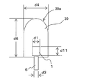
- a cross-section of the tip of the protruding portion protruding outside the device is a semicircular shape or a semi-elliptical shape.
- the cross section of the tip 30a of the protrusion 30 is a semicircular or semi-elliptical shape having an R shape.
- the density distribution of the particles in the major axis direction of the spray pattern can be made substantially uniform, and the density distribution of the fog particles in the major axis direction of the spray pattern can be controlled by forming the R shape.
- FIG. 1C, 1F, and 2C the cross section of the tip 30a of the protrusion 30 is a semicircular or semi-elliptical shape having an R shape.
- the slit width (d1) of the first gas injection unit and the slit width (d2) of the second gas injection unit are from 1 times the outlet orifice diameter (d3) of the liquid outflow unit. It is preferably 1.5 times. This is because it is preferable that the collision cross-sectional area of the liquid is smaller than the collision part or the collision wall when the liquid that has flowed out collides with the collision part or the collision wall between the gas flows. When the collision cross section of the liquid flowing out from the collision part or the collision wall between the gas flows is large, a part of the liquid tends not to be atomized without colliding with the collision part or the collision wall, and the atomization is poor.
- the slit width of the first gas injection unit 1 is d1
- the slit width of the second gas injection unit 2 (not shown)
- the slit width d1 of the gas injection part is smaller than the outlet orifice diameter d3 of the liquid outflow part, a large amount of coarse particles are likely to be generated on both sides in the major axis direction of the spray pattern.
- the orifice diameter (diameter of the cross-sectional circle) of the first and second gas injection units is 1 to 1.5 times the orifice diameter (diameter of the cross-sectional circle) of the liquid outflow portion. The reason is the same as above.
- the width (d4) of the protrusion is greater than 1 and less than or equal to 6 times the slit width (d1) of the first gas injection unit and the slit width (d2) of the second gas injection unit. It is preferably 1.5 times or more and 4 times or less, more preferably 2 times or more and 3 times or less. The larger the width d4, the larger the area in contact with the fog, and the more easily the drop d4 is generated.
- the width (d5) and the slit depth (d6) of the ejection slit portion formed in the projecting portion are not particularly limited, but the gas-liquid mixing area 12 is placed inside the ejection slit portion. It is preferable to have a space that can be arranged.
- the liquid is a continuous flow, intermittent flow or impulse flow liquid.
- the continuous flow is, for example, a columnar liquid flow.
- the intermittent flow is, for example, a liquid flow that flows out at a predetermined interval.
- the impulse flow is a liquid flow that flows out instantaneously at a predetermined timing, for example.
- the liquid is a refined liquid.
- fine liquid particles can be used.
- the liquid particles for example, finely formed by a two-fluid nozzle device, an ultrasonic device, an ultrahigh pressure spray device, an evaporation spray device, or the like. Liquid fine particles.
- the liquid is not particularly limited, and examples thereof include cosmetic liquids such as water, ionized water, and lotions, pharmaceutical liquids such as pharmaceutical liquids, bactericidal liquids, and bactericidal liquids, paints, fuel oils, coating agents, solvents, and resins. These may be used alone or as a mixture of a plurality of types thereof.
- FIG. 7A It is a schematic diagram for demonstrating the inclination of a liquid outflow direction. It is an external appearance perspective view of the liquid atomization apparatus of Embodiment 1.
- FIG. 6A It is a partial cross section schematic diagram of the liquid atomizer of FIG. 6A. It is a front schematic diagram of the liquid atomization apparatus of FIG. 6B. It is the A section enlarged view of the liquid atomization apparatus of FIG. 6A.
- FIG. 7B is a schematic cross-sectional view taken along the line XX of the outer cap portion of FIG. 7B. It is the A section enlarged view of the outer cap part of FIG. 7A. It is the C section enlarged view of the outer cap part of FIG. 7D.
- FIG. 7B is a schematic cross-sectional view taken along the line BB of the outer cap portion of FIG. 7E.
- the liquid atomizing apparatus of this embodiment will be described with reference to FIGS. 6A to 6D.
- the liquid atomizing device shown in FIGS. 6A to 6D is configured as a nozzle device.
- 7A to 7G are views for explaining the outer cap portion.
- Each orifice section is square.
- gas is supplied from the gas passage 80.
- the gas passage portion 80 is connected to a compressor (not shown) and the like, and the gas injection amount, the injection speed, and the like can be set by controlling the compressor.
- the gas passage portion 80 communicates with both the first gas orifice 81 and the second gas orifice, and the injection amount and the injection speed (flow velocity) of each gas injected from the first gas orifice 81 and the second gas orifice are the same. (Or substantially the same).
- liquid is supplied from the liquid passage portion 90.
- the liquid passage portion 90 is connected to a liquid supply portion (not shown), and the liquid supply portion pressurizes the liquid and sends the liquid to the liquid passage portion 90.
- the liquid supply unit sets a liquid feed amount and a liquid feed speed.
- the liquid passage portion 90 is formed in the nozzle main body 99.
- the gas passage portion 80 is formed by a nozzle outer body 89 that is incorporated into the outer wall portion of the nozzle inner body 99 with screws.
- An inner cap portion 95 is incorporated at the tip of the nozzle inner body 99, and a liquid orifice 91 for flowing out the liquid supplied from the liquid passage portion 90 is formed by the inner cap portion 95.
- the cross-sectional shape of the liquid orifice 91 is preferably a circle.
- the liquid orifice 91 extends straight in the major axis direction, and the tip end portion 911 has a diameter smaller than other orifice diameters.
- the outer cap portion 85 is incorporated at the tip of the nozzle outer body 89.
- the screw cap 86 is fixed to the nozzle outer body 89 by screws, thereby fixing the outer cap 85 that is in direct contact with the screw cap 86 and the inner cap 95 that is pressed by the outer cap 85.
- the first gas orifice 81 and the second gas orifice (not shown) form a concave groove having a rectangular cross section on the inner wall surface of the outer cap portion 85 (see the BB cross section in FIGS. 7E and 7G).
- the first gas orifice 81 and the second gas orifice (not shown) having a rectangular cross section are formed by being sealed with the cap portion 95.
- the concave groove 81 is indicated by a slit width d1 and a slit depth d11. Further, the fixing method of each member is not limited to screw fixing, and other connecting means can be used, and a sealing member (not shown) (such as an O-ring) is appropriately incorporated in the gap between the members. May be.
- the outer cap portion 85 is formed with a protruding portion 851 protruding in a convex shape on the outer side of the apparatus.
- a gas-liquid mixing area (not shown) is formed inside the protruding portion 851.
- An ejection slit portion 851a is formed in the projecting portion 851.
- regulating portions 852a and 852b are formed in the vicinity of the bottom of the ejection slit portion 851a along the wide-angle spray direction of the mist.
- the inclination angle ( ⁇ ) formed by the restricting portions 852a and 852b is 60 °.
- the restricting portions 852a and 852b make it easy for the sprayed mist to be ejected forward without adhering to the nozzle tip surface, and even in wide-angle spraying, it is difficult for the nozzle tip portion to generate droplets, and the average particle size in the major axis direction of the spray pattern It becomes almost equal.
- the inclination angle ⁇ is not limited to 60 °.
- the tip cross-section 851b of the protrusion 851 has a semicircular shape.
- the density distribution of particles in the major axis direction of the spray pattern can be made substantially uniform, and the density distribution of fog particles in the major axis direction of the spray pattern can be suitably controlled by making the tip cross-section R-shaped.
- a gas-liquid mixing area (not shown), which is an area where two gas flows collide with one liquid flow, is formed on the spraying direction side from the bottom of the ejection slit portion 851a. Accordingly, it is possible to easily obtain a spray pattern with less taper and a maximum spray angle (wide angle spray angle ⁇ ) of 180 °.
- the outer cap portion 85 and the inner cap portion 95 form the first and second gas orifices.
- the first and second gas orifices may be formed by one member.
- the cross-sectional shape of the first and second gas orifices is not limited to a rectangle, and may be another polygonal shape or a circular shape.
- the collision angle ⁇ between the gas flows is not limited to 110 °, and can be set in the range of 90 ° to 180 °, for example.
- Example 1 Using the liquid atomizing apparatus having the configuration shown in the first embodiment, the presence or absence of dripping was evaluated.
- the ejection slit portion 851a of the projecting portion 851 of Example 1 has a width (d4) of 1 mm, a slit depth (d6) of 0.95 mm, and a slit interval (d5) of 0.3 mm, and the restriction portions 852a and 852b.
- Inclination angle ⁇ is 60 °
- rectangular cross section of first and second gas orifices is slit width (d1) is 0.47 mm
- slit depth (d11) is 0.57 mm
- cross section diameter of liquid orifice tip is ⁇ 0.35 mm It was. Air was used as the gas and water was used as the liquid.
- Example 2 In the first embodiment, the inclination angle of the restricting portions 852a and 852b is 90 °, the air quantity Qa of gas injection is 10.0 (NL / min), and the spray (water) quantity Qw is 50.0 (ml / min). Air pressure Pa, water pressure Pw, and the average particle diameter (SMD) at the center and both ends in the major axis direction of the spray pattern were evaluated. As this comparison, the same evaluation was made with the restriction portions 852a and 852b eliminated (Comparative Example 2). The results are shown in Table 2. In Example 2, the fog had substantially the same average particle diameter at the center and both ends in the major axis direction of the spray pattern.
- Example 3 Evaluation of spray pattern density distribution
- the tip end face 851b of the protrusion 851 is semicircular (described in Table 3 as Example 3).
- Example 3 a projecting portion having a rectangular cross section with an angular tip was evaluated (Comparative Example 3).
- Table 3 a projecting portion having a rectangular cross section with an angular tip was evaluated.
- Example 3 it was confirmed that the density distribution of the fog particles was substantially uniform in the major axis direction of the spray pattern.
- Comparative Example 3 in the major axis direction of the spray pattern, as shown in FIG. 2D, the high-density area and the low-density area of the mist particles were confirmed separately.
- Example 4 the slit width is 1.35 times the diameter of the tip of the liquid orifice
- the central portion and both end portions A and B have substantially uniform particle diameters in the major axis direction of the spray pattern. It was.
- Comparative Example 4 the rectangular cross-sectional size of the gas orifice is excessive and the slit width is 2.24 times the diameter of the tip of the liquid orifice
- the average particle diameter in the central portion is larger than that at both ends in the major axis direction of the spray pattern. It was 2 times or more, and the effect of refining the liquid was low.
- the average particle size (SMD) was measured with a laser diffraction measuring device.
- the measurement position was 150 mm from the nozzle tip on the spray direction axis.
Abstract
The present invention is provided with the following: a first gas spray unit (1) and a second gas spray unit (2) for causing two gas flows to collide with each other; a liquid drain unit (6) for draining a liquid; a gas/liquid mixing area unit (120), which is an area for causing the gas flow sprayed from the first gas spray unit (1), the gas flow sprayed from the second gas spray unit (2), and the liquid drained from the liquid drain unit (6) to collide together thereby atomizing the liquid; a projection part (851) which is formed projecting out from the device along the first gas spray unit (1) and the second gas spray unit (2) to have a convex cross-section shape, the gas/liquid mixing area unit (120) being formed in the interior of the projection part; an ejection slit part (851a) formed on the projection part (851) along a wide angle misting direction of the mist generated in the gas/liquid mixing area unit (120); and regulating parts (852a, 852b) formed along the wide angle misting direction of the mist in the vicinity of the bottom of the ejection slit part (851a).
Description
本発明は、液体を霧化するための液体霧化装置に関する。
The present invention relates to a liquid atomizing apparatus for atomizing a liquid.
従来の霧化技術として、気液混合式(二流体式)、超音波式、超高圧式(100MPa~300MPa)、蒸発式等がある。一般的な二流体ノズルは、気体と液体とを同一噴射方向で噴射させて気液の随伴流によるせん断効果で液体を微細化する。
Conventional atomization techniques include gas-liquid mixing type (two-fluid type), ultrasonic type, ultra-high pressure type (100 MPa to 300 MPa), and evaporation type. A general two-fluid nozzle injects gas and a liquid in the same injection direction, and refines | miniaturizes a liquid by the shear effect by the accompanying flow of a gas-liquid.
また、気液混合式二流体ノズルの一例として、微粒子ミストを生成するための噴霧ノズル装置が知られている(特許文献1)。この噴霧ノズル装置は、第1ノズル部と第2ノズル部を有し、第1ノズル部からの噴霧液と第2ノズル部からの噴霧液とを衝突させて、微粒子ミストを形成することができる。しかしながら、2流体ノズル部を2つ備えるため、コスト高であり、また小型化には適していない。
Also, as an example of a gas-liquid mixing type two-fluid nozzle, a spray nozzle device for generating fine particle mist is known (Patent Document 1). This spray nozzle device has a first nozzle part and a second nozzle part, and can collide the spray liquid from the first nozzle part with the spray liquid from the second nozzle part to form a fine particle mist. . However, since two two-fluid nozzle portions are provided, the cost is high, and it is not suitable for downsizing.
また、従来のノズル構造の場合、噴霧角が広角(例えば80°以上)であれば、その噴霧流が噴霧出口部に付着し、しずくとなりボタ落ちするので、周辺を濡らしてしまい問題となっていた。
Further, in the case of the conventional nozzle structure, if the spray angle is a wide angle (for example, 80 ° or more), the spray flow adheres to the spray outlet portion and drops and drops, so that the surroundings are wetted, which is a problem. It was.
本発明は、上述の従来技術の微細化原理とは異なる原理を用いて、かつ簡単な装置構成で液体を霧化可能な液体霧化装置を提供することを目的とする。
An object of the present invention is to provide a liquid atomizing apparatus capable of atomizing a liquid using a principle different from the above-described prior art miniaturization principle and with a simple apparatus configuration.
本発明の液体霧化装置は、2つの気体流同士を衝突させるための第1気体噴射部および第2気体噴射部と、
液体を流出させるための液体流出部と、
前記第1気体噴射部から噴射された気体流と前記第2気体噴射部から噴射された気体流と前記液体流出部から流出した液体とを衝突させて当該液体を霧化させるエリアである気液混合エリア部と、
装置外側に断面凸状に突出して形成され、内部に前記気液混合エリア部が形成される突出部と、
前記突出部に、前記気液混合エリア部で生成された霧の広角噴霧方向に沿って形成される噴出用スリット部と、
前記噴出用スリット部の底部近傍に、前記霧の広角噴霧方向に向かって傾斜して形成される規制部と、を備える。 The liquid atomization apparatus of the present invention includes a first gas injection unit and a second gas injection unit for causing two gas flows to collide with each other,
A liquid outflow part for flowing out the liquid;
The gas-liquid is an area in which the gas flow injected from the first gas injection unit, the gas flow injected from the second gas injection unit, and the liquid flowing out from the liquid outflow unit collide with each other to atomize the liquid. A mixing area,
A projecting portion that is formed so as to protrude in a cross-sectional convex shape on the outside of the device, and in which the gas-liquid mixing area portion is formed;
The ejection slit portion formed along the wide-angle spray direction of the mist generated in the gas-liquid mixing area portion on the protruding portion,
A restricting portion formed to be inclined toward the wide-angle spray direction of the mist in the vicinity of the bottom of the ejection slit portion.
この構成の作用効果を図1A~図1C(霧化エリア部の断面模式図)を参照しながら説明する。第1、第2気体噴射部1、2から噴射した気体流同士11、21が衝突して、衝突部100が形成される。この衝突部100を含む部分を衝突壁と呼ぶ(図1B)。液体流出部6から流出された液体61は、この衝突壁(衝突部100を含む)に衝突する(図1B)。衝突壁に液体61が衝突することで、液体61が粉砕(霧化)され霧62となる。霧62が発生するエリアを気液混合エリア部120として破線で示す。霧62は、突出部30に形成された噴出用スリット部31の隙間から広角に広がって(扇状に広がって)噴霧される(図2A,図2B参照)。このとき、噴出用スリット部31の底部近傍に霧の広角噴霧方向に向かって規制部32a、32bが形成されている(図1C)。この規制部32a、32bによって、噴霧される霧がノズル先端面に付着せずに前方へ噴出されやすくなり、広角噴霧でもノズル先端部にしずくが発生しにくく、噴霧パターン長径方向の平均粒子径がほぼ均等になる。
The function and effect of this configuration will be described with reference to FIGS. 1A to 1C (schematic cross-sectional views of the atomization area). The gas flows 11 and 21 injected from the first and second gas injection units 1 and 2 collide to form a collision unit 100. A portion including the collision portion 100 is referred to as a collision wall (FIG. 1B). The liquid 61 that has flowed out from the liquid outflow portion 6 collides with the collision wall (including the collision portion 100) (FIG. 1B). When the liquid 61 collides with the collision wall, the liquid 61 is crushed (atomized) to become a mist 62. An area where the mist 62 is generated is indicated by a broken line as the gas-liquid mixing area 120. The mist 62 is spread over a wide angle (spread in a fan shape) from the gap between the ejection slits 31 formed in the protrusion 30 (see FIGS. 2A and 2B). At this time, restricting portions 32a and 32b are formed in the vicinity of the bottom of the ejection slit portion 31 toward the wide-angle spray direction of the mist (FIG. 1C). The restricting portions 32a and 32b make it easy for the sprayed mist to be ejected forward without adhering to the nozzle tip surface, making it difficult for the tip of the nozzle to drop even with wide angle spraying, and the average particle size in the major axis direction of the spray pattern. It becomes almost equal.
上記規制部32a、32bは、噴出用スリット部31の凹溝断面の端部よりも外側(噴霧方向)に、その先端部あるいはその傾斜面が突出して形成されていてもよい。また、上記規制部32a、32bは、噴出用スリット部31の凹溝内部(あるいは突出部30)よりも外側(噴霧方向)に形成されていてもよい。
The restriction portions 32a and 32b may be formed such that the tip end portion or the inclined surface thereof protrudes outside (spraying direction) the end portion of the groove section of the ejection slit portion 31. Further, the restricting portions 32a and 32b may be formed outside (spraying direction) the inside of the recessed groove (or the protruding portion 30) of the ejection slit portion 31.
本発明において、突出部は、気体オリフィスを形成するための部材と一体に形成されていてもよく、別部材で形成されていてもよい。
In the present invention, the protrusion may be formed integrally with a member for forming the gas orifice, or may be formed of a separate member.
本発明の液体霧化装置によれば、気体流同士の衝突部あるいは衝突壁(衝突部を含む)と、液体とを衝突させて衝突粉砕することで、低圧力(低気体圧、低液体圧)、低流量(低気体流量、低液体流量)、低エネルギーで効率的に霧化することができる。また、従来の二流体ノズルに比べ、低気液体積比(または低気液比)で霧化することができる。また、従来の二流体ノズルに比べ、本発明の液体霧化装置は低騒音である。また、本発明の液体霧化装置の構造をシンプルにできる。
According to the liquid atomizing apparatus of the present invention, a collision portion or a collision wall (including a collision portion) between gas flows and a liquid collide with each other to perform collision pulverization, thereby reducing a low pressure (low gas pressure, low liquid pressure). ), Low flow rate (low gas flow rate, low liquid flow rate), low energy and efficient atomization. Moreover, compared with the conventional two-fluid nozzle, it can atomize with a low gas-liquid volume ratio (or low gas-liquid ratio). Moreover, compared with the conventional two-fluid nozzle, the liquid atomization apparatus of the present invention has low noise. Moreover, the structure of the liquid atomization apparatus of this invention can be simplified.
気体噴射部から噴射される気体(気体流)の圧力、流量は、特に制限されないが、本発明の霧化原理によって、低気体圧力、低気体流量で、液体を好適に霧化できる。また、衝突部および衝突壁を構成することになる気体流同士の圧力は、同じまたは略同じに設定することが好ましく、衝突部および衝突壁を構成することになる気体流同士の流量も、同じまたは略同じに設定することが好ましい。また、気体噴射部から噴射される気体流の断面形状は、特に制限されず、例えば、円状、楕円状、矩形状、多角形状が挙げられる。また、衝突部および衝突壁を構成する気体流同士の断面形状は、同一または略同一であることが好ましい。衝突部が変形、サイズ縮小等することを抑制することで、一定の形状、一定サイズの衝突部を維持して、安定した噴霧量で粒子径変動の少ない霧化体を生成するのに好ましい。
Although the pressure and flow rate of the gas (gas flow) injected from the gas injection unit are not particularly limited, the liquid can be suitably atomized with a low gas pressure and a low gas flow rate according to the atomization principle of the present invention. Moreover, it is preferable to set the pressure of the gas flows which will comprise a collision part and a collision wall to be the same or substantially the same, and the flow volume of the gas flows which comprise a collision part and a collision wall is also the same. Or it is preferable to set substantially the same. Moreover, the cross-sectional shape of the gas flow injected from the gas injection unit is not particularly limited, and examples thereof include a circular shape, an elliptical shape, a rectangular shape, and a polygonal shape. Moreover, it is preferable that the cross-sectional shape of the gas flow which comprises a collision part and a collision wall is the same or substantially the same. By suppressing the collision part from being deformed, reduced in size, etc., it is preferable to generate an atomized body that maintains a constant shape and a constant size, and that has a stable spray amount and little particle diameter variation.
液体流出部から流出される液体(液体流)の圧力、流量は、特に制限されないが、本発明の霧化原理によって、低圧力、低流量の液体を好適に霧化できる。また、液体流出部の圧力は、一般的は水道配管の水圧でもよく、液体流出部は、液体を自然落下させる装置であってもよい。本発明において、「液体流出部から流出した液体」には、自然落下速度で落下する液体も含まれる。
Although the pressure and flow rate of the liquid (liquid flow) flowing out from the liquid outflow portion are not particularly limited, the low pressure and low flow rate liquid can be suitably atomized by the atomization principle of the present invention. Further, the pressure of the liquid outflow portion may be generally the water pressure of a water pipe, and the liquid outflow portion may be a device that naturally drops the liquid. In the present invention, the “liquid that has flowed out from the liquid outflow portion” includes liquid that falls at a natural falling speed.
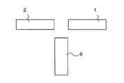
液体流出部と気体噴射部の相対的配置例を図3A~図3Fを参照して説明する。この相対的配置によって、気液衝突位置が規定される。図3Aの配置は、第1、第2気体噴射部1、2が対向配置され、液体流出部6のノズル先端が第1、第2気体噴射部1,2の両ノズル先端外側面部分に接触している。図3Bの配置は、第1、第2気体噴射部1、2が対向配置され、第1、第2気体噴射部1,2の両ノズル先端と液体流出部6のノズル先端部とが接触している。図3Bの配置は図3Aの配置よりも、流出される液体流量が多く、かつ逆流も小さい傾向となる。図3Cの配置は、第1、第2気体噴射部1、2の両ノズル先端間に、液体流出部6のノズルが入り込んだ配置である。図3Dの配置は、図3Bの配置と比較して、第1、第2気体噴射部1,2の両ノズルの間隔が、図3Bのそれよりも大きい配置である。図3Eの配置は、図3Bの配置と比較して、液体流出部6が衝突壁から遠ざかった配置である。また、液体流出部は1つを例示しているが、液体流出部は2つ以上であってもよく、図3Fでは、液体流出部は2つ配置されている。なお、図3A~3Fは、突出部等の他の部材を省略して示している。
A relative arrangement example of the liquid outflow portion and the gas injection portion will be described with reference to FIGS. 3A to 3F. This relative arrangement defines the gas-liquid collision position. In the arrangement shown in FIG. 3A, the first and second gas injection units 1 and 2 are opposed to each other, and the nozzle tip of the liquid outflow unit 6 contacts the outer surface of both nozzle tips of the first and second gas injection units 1 and 2. is doing. In the arrangement of FIG. 3B, the first and second gas injection units 1 and 2 face each other, and both the nozzle tips of the first and second gas injection units 1 and 2 and the nozzle tip of the liquid outflow unit 6 are in contact with each other. ing. The arrangement of FIG. 3B tends to have a larger liquid flow rate and a smaller backflow than the arrangement of FIG. 3A. The arrangement in FIG. 3C is an arrangement in which the nozzle of the liquid outflow portion 6 enters between the nozzle tips of the first and second gas injection units 1 and 2. The arrangement of FIG. 3D is an arrangement in which the distance between the nozzles of the first and second gas injection units 1 and 2 is larger than that of FIG. 3B as compared to the arrangement of FIG. 3B. The arrangement of FIG. 3E is an arrangement in which the liquid outflow portion 6 is moved away from the collision wall as compared with the arrangement of FIG. 3B. Moreover, although one liquid outflow part is illustrated, two or more liquid outflow parts may be sufficient, and in FIG. 3F, two liquid outflow parts are arrange | positioned. In FIGS. 3A to 3F, other members such as protrusions are omitted.
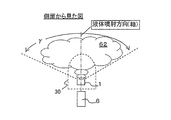
上記生成される霧は、気体流同士の衝突部から排出される排出気体流とともに噴霧される。この排出気体流によって噴霧パターンが形成される。噴霧パターンは、例えば、2つの噴射された気体流の衝突で形成された衝突部と液体(液体流)とが衝突した場合には、噴出用スリット部31の開放方向に、液体流出方向軸を中心にして幅広の扇状に形成され、その断面形状は楕円状または長円状(図2A、図2B)となる。気体流同士が衝突した衝突面に平行に(衝突面が拡張する方向に)、衝突した(衝突後の)気体が拡散しており、この方向に霧62が扇状に広がって噴出されることになる。本発明において、霧62の広角噴霧角γは、80°以上であり、100°~180°の広角噴霧角も可能となる。
The generated mist is sprayed together with the exhaust gas flow discharged from the collision part of the gas flows. This exhaust gas flow forms a spray pattern. In the spray pattern, for example, when a collision part formed by collision of two jetted gas flows and a liquid (liquid flow) collide, the liquid outflow direction axis is set in the opening direction of the ejection slit part 31. It is formed in a fan shape that is wide at the center, and its cross-sectional shape is elliptical or elliptical (FIGS. 2A and 2B). In parallel with the collision surface where the gas flows collide (in the direction in which the collision surface expands), the gas that has collided (after the collision) is diffused, and the mist 62 spreads in a fan shape and is ejected in this direction. Become. In the present invention, the wide-angle spray angle γ of the mist 62 is 80 ° or more, and a wide-angle spray angle of 100 ° to 180 ° is also possible.
上記発明の一実施形態として、前記第1気体噴射部の噴射方向軸と前記第2気体噴射部の噴射方向軸との交差角度が90°~180°の範囲であることが好ましい。第1気体噴射部1および第2気体噴射部2のそれぞれの噴射方向軸が交差する角度範囲は、第1気体噴射部1から噴射された気体と第2気体噴射部2から噴射された気体の衝突角に相当する。例えば、「衝突角α」は、90°~220°であり、好ましくは90°~180°であり、より好ましくは110°~180°である。図4に衝突角αを示す。180°より小さい衝突角を形成している衝突部に液体(液体流)を衝突させた場合に、この衝突角の角度が小さいほど、従来の二流体ノズルの原理(気体と液体とを同一噴射方向で噴射させて気液の随伴流によるせん断効果で液体を微細化する)に類似するため、本発明の上記微細化原理の効果が低くなる傾向になるが、一方で、衝突角の角度が小さいほど、流出された液体の逆流が抑えられる傾向である。また、180°より大きい衝突角を形成している衝突部に液体を衝突させた場合に、衝突角の角度が大きいほど、噴射された気体および衝突して広がった気体が、液体を押し戻すように作用して液体を逆流させてしまう傾向である。なお、図4において、液体流出部6のノズル先端が、第1、第2気体噴射部1,2の両ノズル先端と接触しているが、これに制限されず、液体流出部6のノズル先端位置が、第1、第2気体噴射部1,2の両ノズル間に配置させていてもよく、図4の配置よりも第1、第2気体噴射部1,2から距離を置いて配置されていてもよい。
As an embodiment of the present invention, it is preferable that an intersection angle between an injection direction axis of the first gas injection unit and an injection direction axis of the second gas injection unit is in a range of 90 ° to 180 °. The angle ranges in which the respective injection direction axes of the first gas injection unit 1 and the second gas injection unit 2 intersect are the gas injected from the first gas injection unit 1 and the gas injected from the second gas injection unit 2. Corresponds to the collision angle. For example, the “collision angle α” is 90 ° to 220 °, preferably 90 ° to 180 °, and more preferably 110 ° to 180 °. FIG. 4 shows the collision angle α. When a liquid (liquid flow) collides with a collision part that forms a collision angle smaller than 180 °, the smaller the angle of this collision angle, the more the principle of the conventional two-fluid nozzle (the same injection of gas and liquid) The effect of the above-mentioned micronization principle of the present invention tends to be low, while the angle of the collision angle is low. The smaller the size, the more the backflow of the spilled liquid tends to be suppressed. In addition, when a liquid collides with a collision part that forms a collision angle greater than 180 °, the larger the collision angle, the more the jetted gas and the gas that has collided and spread back the liquid. It tends to act and reverse the liquid. In FIG. 4, the nozzle tip of the liquid outflow portion 6 is in contact with both nozzle tips of the first and second gas injection units 1 and 2, but is not limited to this, and the nozzle tip of the liquid outflow portion 6. The position may be arranged between both nozzles of the first and second gas injection units 1 and 2 and is arranged at a distance from the first and second gas injection units 1 and 2 than the arrangement of FIG. It may be.
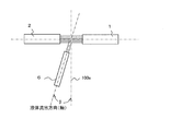
上記発明の実施形態例として、図5に示すように、衝突部100の衝突面100aに対して液体の流出方向軸が傾いている例を示す。この傾き角βとしては、0°(直交位置)から±80°の範囲、好ましくは0°から±45°、より好ましくは0°から±30°、さらに好ましくは0°から±15°の範囲である。傾き角βが小さくなるほど、霧の生成効率(霧化効率)が高い傾向となる。
As an embodiment of the above invention, an example in which the liquid outflow direction axis is inclined with respect to the collision surface 100a of the collision unit 100 as shown in FIG. The inclination angle β ranges from 0 ° (orthogonal position) to ± 80 °, preferably from 0 ° to ± 45 °, more preferably from 0 ° to ± 30 °, and even more preferably from 0 ° to ± 15 °. It is. As the inclination angle β decreases, the fog generation efficiency (atomization efficiency) tends to increase.
上記発明の前記規制部の傾斜角度は、180°より小さい傾斜角であればよく、例えば、噴霧方向に開くように、10°~160°の角度範囲が挙げられる。好ましい実施形態としては、20°~150°の角度範囲で傾斜して形成されていることが好ましい。図1Dは、規制部32a、32bの傾斜角度θを示す。傾斜角度θとしては、20°~150°の範囲が好ましく、より好ましくは、40°~120°であり、さらに好ましくは、60°~90°である。θが小さくなるほど、噴霧が直進的になり、噴霧出口周辺に霧がより付着しにくくなるが、噴霧パターンの長径が短くなり広角噴霧パターンでなくなる。一方、θが大きくなるほど噴霧出口周辺に霧が付着しやすく、しずくになりやすくなる。θが60°~90°の範囲では、しずく発生の抑制効果が高く、広角噴霧パターンを維持できる。また、本発明の規制部によって、傾斜角度θ(=θ1+θ2)をコントロールすることで、噴霧パターンの長径の長さ、噴霧パターンを可変にコントロールできる。図1Dに示すように、規制部32a、規制部32bは、噴霧方向中心軸から、同じ傾斜角(θ/2ずつ)であることが必ずしも必要ではなく、得たい噴霧パターンに応じて、θ1とθ2の角度が異なっていてもよい。
The inclination angle of the restricting portion of the present invention may be an inclination angle smaller than 180 °, and examples thereof include an angle range of 10 ° to 160 ° so as to open in the spraying direction. In a preferred embodiment, it is preferably formed to be inclined within an angle range of 20 ° to 150 °. FIG. 1D shows the inclination angle θ of the restricting portions 32a and 32b. The inclination angle θ is preferably in the range of 20 ° to 150 °, more preferably 40 ° to 120 °, and still more preferably 60 ° to 90 °. As θ becomes smaller, the spray becomes straighter and the mist becomes less likely to adhere to the periphery of the spray outlet, but the major axis of the spray pattern becomes shorter and the wide-angle spray pattern is lost. On the other hand, as θ increases, mist tends to adhere to the periphery of the spray outlet, and drops tend to be formed. When θ is in the range of 60 ° to 90 °, the effect of suppressing the generation of drips is high, and a wide-angle spray pattern can be maintained. Moreover, the length of the major axis of the spray pattern and the spray pattern can be variably controlled by controlling the inclination angle θ (= θ1 + θ2) by the restricting portion of the present invention. As shown in FIG. 1D, the restricting portion 32a and the restricting portion 32b are not necessarily required to have the same inclination angle (in increments of θ / 2) from the central axis in the spray direction. Depending on the spray pattern desired to be obtained, θ1 and The angle of θ2 may be different.
上記発明の一実施形態として、前記気液混合エリアが、前記噴出用スリット部の底部よりも噴霧方向側に形成されていることが好ましい。
As an embodiment of the invention, it is preferable that the gas-liquid mixing area is formed on the spraying direction side with respect to the bottom of the ejection slit portion.
この構成では、図1Eに示すように、気液混合エリア120(気体流同士および液体流との衝突部エリア)が、噴出用スリット部31の底部(底面)31aよりも噴霧方向側に形成される。従来の二流体ノズルでは最大噴霧角が100°未満であり、かつ噴霧距離が遠くなれば先細りパターンになっていたが(100°以上の噴霧角で使用すると実用性が著しく低下していたが)、本発明によれば、先細りが少なく、かつ最大噴霧角(広角噴霧角度γ)が180°の噴霧パターンを簡単に得ることができる。さらに、本発明の霧化原理による高い霧化効果と広角噴霧による噴霧パターン断面の低密度により、従来の二流体ノズルよりも大幅な低気水比で微粒化ができる。
In this configuration, as shown in FIG. 1E, the gas-liquid mixing area 120 (the collision area between the gas flows and the liquid flow) is formed on the spraying direction side of the bottom (bottom surface) 31a of the ejection slit portion 31. The In the conventional two-fluid nozzle, the maximum spray angle is less than 100 °, and when the spray distance is long, the taper pattern is formed (although the practicality is remarkably lowered when used at a spray angle of 100 ° or more). According to the present invention, it is possible to easily obtain a spray pattern with little taper and a maximum spray angle (wide angle spray angle γ) of 180 °. Furthermore, due to the high atomization effect by the atomization principle of the present invention and the low density of the spray pattern cross section by the wide angle spray, atomization can be achieved at a significantly lower air-water ratio than the conventional two-fluid nozzle.
上記発明の一実施形態として、前記突出部の装置外部に突出している先端部断面が、半円形状または半楕円形状であることが好ましい。
As an embodiment of the present invention, it is preferable that a cross-section of the tip of the protruding portion protruding outside the device is a semicircular shape or a semi-elliptical shape.
この構成では、図1C、図1F、図2Cに示すように、突出部30の先端部30aの断面が、R形状を有する半円形状または半楕円形状である。これによって、噴霧パターンの長径方向の粒子の密度分布を略均一にでき、R形状にすることで、噴霧パターンの長径方向の霧粒子の密度分布を制御できる。一方、図2Dに示すように、先端部30bが角ばっていると、そこを通過する霧が膨張するときに、霧粒子が引っかかり(接触可能面積が大きいため引っかかりやすい)、噴霧パターンにスジや粗粒子が発生しやすく、また噴霧パターンの中央部分の霧粒子が他エリアよりも高密度になりやすい。
In this configuration, as shown in FIGS. 1C, 1F, and 2C, the cross section of the tip 30a of the protrusion 30 is a semicircular or semi-elliptical shape having an R shape. Thereby, the density distribution of the particles in the major axis direction of the spray pattern can be made substantially uniform, and the density distribution of the fog particles in the major axis direction of the spray pattern can be controlled by forming the R shape. On the other hand, as shown in FIG. 2D, if the tip 30b is angular, when the mist passing through it expands, the mist particles are caught (it is easy to catch because the contactable area is large), Coarse particles are likely to be generated, and fog particles in the central portion of the spray pattern are likely to be denser than other areas.
本発明の一実施形態として、前記第1気体噴射部のスリット幅(d1)および前記第2気体噴射部のスリット幅(d2)が、前記液体流出部の出口オリフィス直径(d3)の1倍~1.5倍であることが好ましい。流出された液体と、気体流同士の衝突部または衝突壁とを衝突させる場合に、衝突部または衝突壁より液体の衝突断面積が小さいことが好ましいからである。気体流同士の衝突部または衝突壁よりも流出した液体の衝突断面が大きいと、液体の一部が衝突部または衝突壁に衝突せずに霧化されない傾向にあり、微粒化が悪い。
As one embodiment of the present invention, the slit width (d1) of the first gas injection unit and the slit width (d2) of the second gas injection unit are from 1 times the outlet orifice diameter (d3) of the liquid outflow unit. It is preferably 1.5 times. This is because it is preferable that the collision cross-sectional area of the liquid is smaller than the collision part or the collision wall when the liquid that has flowed out collides with the collision part or the collision wall between the gas flows. When the collision cross section of the liquid flowing out from the collision part or the collision wall between the gas flows is large, a part of the liquid tends not to be atomized without colliding with the collision part or the collision wall, and the atomization is poor.
この構成では、図1Fに示すように、第1気体噴射部1のスリット幅がd1であり、不図示の第2気体噴射部2のスリット幅がd2であり、d1=d2の寸法設定である。そして、液体流出部6の出口オリフィス直径がd3であるとき、d3=d1~1.5×d1の範囲である。これによって、均等な粒子径と拡散分布が得られる。気体噴射部のスリット幅d1が、液体流出部の出口オリフィス直径d3より過大であれば、噴霧パターン中央部の微粒化が低下し、粗粒子が発生しやすい。一方、気体噴射部のスリット幅d1が、液体流出部の出口オリフィス直径d3より過小であれば、噴霧パターンの長径方向の両サイドに粗粒子が多く発生しやすい。
In this configuration, as shown in FIG. 1F, the slit width of the first gas injection unit 1 is d1, the slit width of the second gas injection unit 2 (not shown) is d2, and the dimension setting is d1 = d2. . When the outlet orifice diameter of the liquid outflow portion 6 is d3, d3 = d1 to 1.5 × d1. Thereby, a uniform particle size and diffusion distribution can be obtained. If the slit width d1 of the gas injection part is larger than the outlet orifice diameter d3 of the liquid outflow part, atomization at the central part of the spray pattern is reduced and coarse particles are likely to be generated. On the other hand, if the slit width d1 of the gas injection part is smaller than the outlet orifice diameter d3 of the liquid outflow part, a large amount of coarse particles are likely to be generated on both sides in the major axis direction of the spray pattern.
また、第1、第2気体噴射部のオリフィス径(断面円の直径)が、液体流出部のオリフィス径(断面円の直径)の1倍から1.5倍であることが好ましい。上記と同様の理由である。
Further, it is preferable that the orifice diameter (diameter of the cross-sectional circle) of the first and second gas injection units is 1 to 1.5 times the orifice diameter (diameter of the cross-sectional circle) of the liquid outflow portion. The reason is the same as above.
本発明の一実施形態として、突出部の幅(d4)が、第1気体噴射部のスリット幅(d1)および第2気体噴射部のスリット幅(d2)の1倍より大きく6倍以下であることが好ましく、より好ましくは1.5倍以上4倍以下であり、さらに好ましくは2倍以上3倍以下である。幅d4が大きくなるほど、霧と接触する面積が大きくなりしずく発生がしやすくなる。
As an embodiment of the present invention, the width (d4) of the protrusion is greater than 1 and less than or equal to 6 times the slit width (d1) of the first gas injection unit and the slit width (d2) of the second gas injection unit. It is preferably 1.5 times or more and 4 times or less, more preferably 2 times or more and 3 times or less. The larger the width d4, the larger the area in contact with the fog, and the more easily the drop d4 is generated.
また、図1Eに示すように、突出部に形成された噴出用スリット部の幅(d5)とスリット深さ(d6)は、特に制限されないが、気液混合エリア12を噴出用スリット部内部に配置できる程度の空間を有していることが好ましい。
Further, as shown in FIG. 1E, the width (d5) and the slit depth (d6) of the ejection slit portion formed in the projecting portion are not particularly limited, but the gas-liquid mixing area 12 is placed inside the ejection slit portion. It is preferable to have a space that can be arranged.
上記発明の一実施形態として、前記液体が連続流、間欠流またはインパルス流の液体であることが好ましい。連続流は、例えば、柱状の液体流である。間欠流は、例えば、所定間隔で流出する液体流である。インパルス流は、例えば、所定のタイミングで瞬間的に流出する液体流である。液体供給装置等で、液体の流出方法を自在に制御することで、霧化タイミング、生成される霧の噴霧量を自在に制御することができる。
As an embodiment of the invention, it is preferable that the liquid is a continuous flow, intermittent flow or impulse flow liquid. The continuous flow is, for example, a columnar liquid flow. The intermittent flow is, for example, a liquid flow that flows out at a predetermined interval. The impulse flow is a liquid flow that flows out instantaneously at a predetermined timing, for example. By controlling the liquid flow-out method freely with a liquid supply device or the like, the atomization timing and the amount of fog generated can be controlled freely.
上記発明の一実施形態として、前記液体が微細化された液体である。液体流出部から流出される液体として、微細化された液微粒子を用いることができ、液微粒子としては、例えば、二流体ノズル装置、超音波装置、超高圧噴霧装置、蒸発式噴霧装置等で微細化された液微粒子が挙げられる。
As an embodiment of the invention, the liquid is a refined liquid. As the liquid flowing out from the liquid outflow part, fine liquid particles can be used. As the liquid particles, for example, finely formed by a two-fluid nozzle device, an ultrasonic device, an ultrahigh pressure spray device, an evaporation spray device, or the like. Liquid fine particles.
上記気体としては、特に制限されないが、例えば、空気、清浄空気(クリーンエア)、窒素、不活性ガス、燃料混合エア、酸素等が単独で、あるいはそれら複数種類の混合気体が挙げられ、使用目的に応じて適宜設定可能である。
Although it does not restrict | limit especially as said gas, For example, air, clean air (clean air), nitrogen, an inert gas, fuel mixing air, oxygen, etc. are individual, or those multiple types of mixed gas is mentioned, Purpose of use It can be set appropriately according to
上記液体としては、特に制限されないが、例えば、水、イオン化水、化粧水等の化粧薬液、医薬液、殺菌液、除菌液等の薬液、塗料、燃料油、コーティング剤、溶剤、樹脂等が単独で、あるいはそれら複数種類の混合液体が挙げられる。
The liquid is not particularly limited, and examples thereof include cosmetic liquids such as water, ionized water, and lotions, pharmaceutical liquids such as pharmaceutical liquids, bactericidal liquids, and bactericidal liquids, paints, fuel oils, coating agents, solvents, and resins. These may be used alone or as a mixture of a plurality of types thereof.
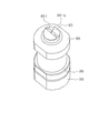
(実施形態1)
本実施形態の液体霧化装置を図6A~6Dを参照しながら説明する。図6A~6Dに示す液体霧化装置は、ノズル装置として構成されている。図7A~7Gは、外キャップ部を説明するための図である。第1気体噴射部を構成する第1気体オリフィス81と、第2気体噴射部を構成する第2気体オリフィス(不図示)とが、衝突角(α)=110°で気体流同士を衝突させるように配置されている。それぞれのオリフィス断面が四角形である。 (Embodiment 1)
The liquid atomizing apparatus of this embodiment will be described with reference to FIGS. 6A to 6D. The liquid atomizing device shown in FIGS. 6A to 6D is configured as a nozzle device. 7A to 7G are views for explaining the outer cap portion. Thefirst gas orifice 81 constituting the first gas injection unit and the second gas orifice (not shown) constituting the second gas injection unit cause the gas flows to collide with each other at a collision angle (α) = 110 °. Is arranged. Each orifice section is square.
本実施形態の液体霧化装置を図6A~6Dを参照しながら説明する。図6A~6Dに示す液体霧化装置は、ノズル装置として構成されている。図7A~7Gは、外キャップ部を説明するための図である。第1気体噴射部を構成する第1気体オリフィス81と、第2気体噴射部を構成する第2気体オリフィス(不図示)とが、衝突角(α)=110°で気体流同士を衝突させるように配置されている。それぞれのオリフィス断面が四角形である。 (Embodiment 1)
The liquid atomizing apparatus of this embodiment will be described with reference to FIGS. 6A to 6D. The liquid atomizing device shown in FIGS. 6A to 6D is configured as a nozzle device. 7A to 7G are views for explaining the outer cap portion. The
図6Bに示すように、気体通路部80から気体が供給される。気体通路部80が不図示のコンプレッサー等に接続されて、コンプレッサーを制御することで気体の噴射量、噴射速度等を設定できる。気体通路部80は第1気体オリフィス81および第2気体オリフィスの両方に通じており、第1気体オリフィス81および第2気体オリフィスから噴射されるそれぞれの気体の噴射量および噴射速度(流速)は同じ(あるいは略同じ)に設定される。
As shown in FIG. 6B, gas is supplied from the gas passage 80. The gas passage portion 80 is connected to a compressor (not shown) and the like, and the gas injection amount, the injection speed, and the like can be set by controlling the compressor. The gas passage portion 80 communicates with both the first gas orifice 81 and the second gas orifice, and the injection amount and the injection speed (flow velocity) of each gas injected from the first gas orifice 81 and the second gas orifice are the same. (Or substantially the same).
また、液体通路部90から液体が供給される。液体通路部90が不図示の液体供給部に接続され、液体供給部が液体を加圧して液体通路部90に液送する。液体供給部は、液体の液送量、液送速度を設定する。なお、液体通路部90は、ノズル内本体99に形成される。気体通路部80は、ノズル内本体99の外壁部にネジ固定で組み込んだノズル外本体89で形成されている。
Further, liquid is supplied from the liquid passage portion 90. The liquid passage portion 90 is connected to a liquid supply portion (not shown), and the liquid supply portion pressurizes the liquid and sends the liquid to the liquid passage portion 90. The liquid supply unit sets a liquid feed amount and a liquid feed speed. The liquid passage portion 90 is formed in the nozzle main body 99. The gas passage portion 80 is formed by a nozzle outer body 89 that is incorporated into the outer wall portion of the nozzle inner body 99 with screws.
ノズル内本体99の先端に内キャップ部95が組み込まれ、この内部キャップ部95によって、液体通路部90からの供給される液体を流出するための液体オリフィス91が形成されている。液体オリフィス91の断面形状は円であることが好ましい。本実施形態では、液体オリフィス91がその長軸方向にストレートに延び、その先端部911は、他のオリフィス径よりも小さい径である。
An inner cap portion 95 is incorporated at the tip of the nozzle inner body 99, and a liquid orifice 91 for flowing out the liquid supplied from the liquid passage portion 90 is formed by the inner cap portion 95. The cross-sectional shape of the liquid orifice 91 is preferably a circle. In the present embodiment, the liquid orifice 91 extends straight in the major axis direction, and the tip end portion 911 has a diameter smaller than other orifice diameters.
ノズル外本体89の先端に外キャップ部85が組み込まれる。ネジ止部86がノズル外本体89にネジ固定されることで、このネジ止部86に直接に接する外キャップ部85および外キャップ部85に押圧される内キャップ部95をそれぞれ固定する。第1気体オリフィス81、第2気体オリフィス(不図示)は、外キャップ部85の内壁面に断面矩形の凹溝を形成し(図7E、7GのB-B断面参照)、この凹溝が内キャップ部95で密閉されることで断面矩形の第1気体オリフィス81、第2気体オリフィス(不図示)を形成している。凹溝81は、スリット幅d1、スリット深さd11で示される。また、各部材の固定方法はネジ固定に限定されず、他の連結手段を用いることができ、また、各部材間の隙間には不図示のシール部材(例えばOリング等)が適宜組み込まれていてもよい。
The outer cap portion 85 is incorporated at the tip of the nozzle outer body 89. The screw cap 86 is fixed to the nozzle outer body 89 by screws, thereby fixing the outer cap 85 that is in direct contact with the screw cap 86 and the inner cap 95 that is pressed by the outer cap 85. The first gas orifice 81 and the second gas orifice (not shown) form a concave groove having a rectangular cross section on the inner wall surface of the outer cap portion 85 (see the BB cross section in FIGS. 7E and 7G). The first gas orifice 81 and the second gas orifice (not shown) having a rectangular cross section are formed by being sealed with the cap portion 95. The concave groove 81 is indicated by a slit width d1 and a slit depth d11. Further, the fixing method of each member is not limited to screw fixing, and other connecting means can be used, and a sealing member (not shown) (such as an O-ring) is appropriately incorporated in the gap between the members. May be.
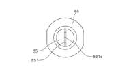
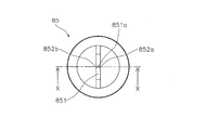
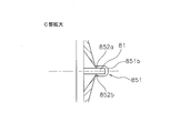
図7A~7Dに示すように、外キャップ部85には、装置外側に断面凸状に突出した突出部851が形成されている。この突出部851の内部に気液混合エリア部(不図示)が形成される。この突出部851に、噴出用スリット部851aが形成されている。さらに、図7Fに示すように、噴出用スリット部851aの底部近傍に霧の広角噴霧方向に沿って規制部852a、852bが形成される。本実施形態において、この規制部852a、852bで形成される傾斜角度(θ)は、60°である。この規制部852a、852bによって、噴霧される霧がノズル先端面に付着せずに前方へ噴出されやすくなり、広角噴霧でもノズル先端部にしずくが発生しにくく、噴霧パターン長径方向の平均粒子径がほぼ均等になる。なお、傾斜角度θは60°に制限されない。
As shown in FIGS. 7A to 7D, the outer cap portion 85 is formed with a protruding portion 851 protruding in a convex shape on the outer side of the apparatus. A gas-liquid mixing area (not shown) is formed inside the protruding portion 851. An ejection slit portion 851a is formed in the projecting portion 851. Further, as shown in FIG. 7F, regulating portions 852a and 852b are formed in the vicinity of the bottom of the ejection slit portion 851a along the wide-angle spray direction of the mist. In the present embodiment, the inclination angle (θ) formed by the restricting portions 852a and 852b is 60 °. The restricting portions 852a and 852b make it easy for the sprayed mist to be ejected forward without adhering to the nozzle tip surface, and even in wide-angle spraying, it is difficult for the nozzle tip portion to generate droplets, and the average particle size in the major axis direction of the spray pattern It becomes almost equal. Note that the inclination angle θ is not limited to 60 °.
また、図7Fに示すように、突出部851の先端断面851bは、半円形状である。これによって、噴霧パターンの長径方向の粒子の密度分布を略均一にでき、先端断面をR形状にすることで、噴霧パターンの長径方向の霧粒子の密度分布を好適に制御できる。
Further, as shown in FIG. 7F, the tip cross-section 851b of the protrusion 851 has a semicircular shape. Thereby, the density distribution of particles in the major axis direction of the spray pattern can be made substantially uniform, and the density distribution of fog particles in the major axis direction of the spray pattern can be suitably controlled by making the tip cross-section R-shaped.
また、2本の気体流同士と1本の液体流が衝突するエリアである気液混合エリア(不図示)が、噴出用スリット部851aの底部よりも噴霧方向側に形成されている。これによって、先細りが少なく、かつ最大噴霧角(広角噴霧角度γ)が180°の噴霧パターンを簡単に得ることができる。
Further, a gas-liquid mixing area (not shown), which is an area where two gas flows collide with one liquid flow, is formed on the spraying direction side from the bottom of the ejection slit portion 851a. Accordingly, it is possible to easily obtain a spray pattern with less taper and a maximum spray angle (wide angle spray angle γ) of 180 °.
上記実施形態1では、外キャップ部85と内キャップ部95とで、第1、第2気体オリフィスを形成しているが、一部材で第1、第2気体オリフィスを形成してもよい。また、第1、2気体オリフィスの断面形状が矩形に限定されず、他の多角形状でもよく、円状でもよい。また、気体流同士の衝突角αは、110°に限定されず、例えば、90°~180°の範囲で設定できる。
In the first embodiment, the outer cap portion 85 and the inner cap portion 95 form the first and second gas orifices. However, the first and second gas orifices may be formed by one member. Moreover, the cross-sectional shape of the first and second gas orifices is not limited to a rectangle, and may be another polygonal shape or a circular shape. Further, the collision angle α between the gas flows is not limited to 110 °, and can be set in the range of 90 ° to 180 °, for example.
(実施例1)
上記実施形態1に示す構成の液体霧化装置を用いて、しずく発生の有無を評価した。実施例1の突出部851の噴出用スリット部851aは、幅(d4)が1mm、スリット深さ(d6)が0.95mm、スリット間隔(d5)が0.3mmとし、規制部852a、852bの傾斜角度θが60°、第1、第2気体オリフィスの矩形断面がスリット幅(d1)が0.47mm、スリット深さ(d11)が0.57mm、液体オリフィス先端部の断面直径がφ0.35mmとした。気体に空気を用い、液体に水を用いた。気体噴射の空気量Qaを10.0(NL/min)、噴霧(水)量Qwを25.0(ml/min)とした場合、および気体噴射の空気量Qaを10.0(NL/min)、噴霧(水)量Qwを50.0(ml/min)とした場合のそれぞれの空気圧Pa、水圧Pw、噴霧角、平均粒子径(SMD)、しずく量を評価した。その結果を表1に示す。いずれの場合もしずくが発生しないことを確認できた。一方、この実施例1において、比較例1として規制部852a、852bを無くしたもので同じ評価を行ったところ、しずくが発生したことを確認した。 Example 1
Using the liquid atomizing apparatus having the configuration shown in the first embodiment, the presence or absence of dripping was evaluated. The ejection slitportion 851a of the projecting portion 851 of Example 1 has a width (d4) of 1 mm, a slit depth (d6) of 0.95 mm, and a slit interval (d5) of 0.3 mm, and the restriction portions 852a and 852b. Inclination angle θ is 60 °, rectangular cross section of first and second gas orifices is slit width (d1) is 0.47 mm, slit depth (d11) is 0.57 mm, and cross section diameter of liquid orifice tip is φ0.35 mm It was. Air was used as the gas and water was used as the liquid. When the air quantity Qa of gas injection is 10.0 (NL / min), the spray (water) quantity Qw is 25.0 (ml / min), and the air quantity Qa of gas injection is 10.0 (NL / min) ), Each air pressure Pa, water pressure Pw, spray angle, average particle diameter (SMD), and amount of drop when the spray (water) amount Qw was 50.0 (ml / min) were evaluated. The results are shown in Table 1. In either case, it was confirmed that no drops were generated. On the other hand, when the same evaluation was performed in Example 1 with the restriction portions 852a and 852b removed as Comparative Example 1, it was confirmed that a drop was generated.
上記実施形態1に示す構成の液体霧化装置を用いて、しずく発生の有無を評価した。実施例1の突出部851の噴出用スリット部851aは、幅(d4)が1mm、スリット深さ(d6)が0.95mm、スリット間隔(d5)が0.3mmとし、規制部852a、852bの傾斜角度θが60°、第1、第2気体オリフィスの矩形断面がスリット幅(d1)が0.47mm、スリット深さ(d11)が0.57mm、液体オリフィス先端部の断面直径がφ0.35mmとした。気体に空気を用い、液体に水を用いた。気体噴射の空気量Qaを10.0(NL/min)、噴霧(水)量Qwを25.0(ml/min)とした場合、および気体噴射の空気量Qaを10.0(NL/min)、噴霧(水)量Qwを50.0(ml/min)とした場合のそれぞれの空気圧Pa、水圧Pw、噴霧角、平均粒子径(SMD)、しずく量を評価した。その結果を表1に示す。いずれの場合もしずくが発生しないことを確認できた。一方、この実施例1において、比較例1として規制部852a、852bを無くしたもので同じ評価を行ったところ、しずくが発生したことを確認した。 Example 1
Using the liquid atomizing apparatus having the configuration shown in the first embodiment, the presence or absence of dripping was evaluated. The ejection slit

(実施例2)
上記実施例1において、規制部852a、852bの傾斜角度を90°とし、気体噴射の空気量Qaを10.0(NL/min)、噴霧(水)量Qwを50.0(ml/min)とした場合の空気圧Pa、水圧Pw、スプレーパターンの長径方向の中央部および両端部の平均粒子径(SMD)を評価した。この比較として、規制部852a、852bを無くしたもので同じ評価をした(比較例2)。その結果を表2に示す。実施例2では、スプレーパターンの長径方向の中央部と両端部とで霧が略同じ平均粒子径であった。一方、比較例2ではスプレーパターンの長径方向の両端部の方の霧の平均粒子径が明らかに大きかった、規制部852a、852bがあることで、スプレーパターンの長径方向における霧の平均粒子径分布が略均一になることを確認できた。 (Example 2)
In the first embodiment, the inclination angle of the restricting portions 852a and 852b is 90 °, the air quantity Qa of gas injection is 10.0 (NL / min), and the spray (water) quantity Qw is 50.0 (ml / min). Air pressure Pa, water pressure Pw, and the average particle diameter (SMD) at the center and both ends in the major axis direction of the spray pattern were evaluated. As this comparison, the same evaluation was made with the restriction portions 852a and 852b eliminated (Comparative Example 2). The results are shown in Table 2. In Example 2, the fog had substantially the same average particle diameter at the center and both ends in the major axis direction of the spray pattern. On the other hand, in Comparative Example 2, the average particle diameter distribution of the mist in the major axis direction of the spray pattern is due to the restriction portions 852a and 852b in which the average particle diameter of the mist toward the both ends in the major axis direction of the spray pattern is clearly large. Was confirmed to be substantially uniform.
上記実施例1において、規制部852a、852bの傾斜角度を90°とし、気体噴射の空気量Qaを10.0(NL/min)、噴霧(水)量Qwを50.0(ml/min)とした場合の空気圧Pa、水圧Pw、スプレーパターンの長径方向の中央部および両端部の平均粒子径(SMD)を評価した。この比較として、規制部852a、852bを無くしたもので同じ評価をした(比較例2)。その結果を表2に示す。実施例2では、スプレーパターンの長径方向の中央部と両端部とで霧が略同じ平均粒子径であった。一方、比較例2ではスプレーパターンの長径方向の両端部の方の霧の平均粒子径が明らかに大きかった、規制部852a、852bがあることで、スプレーパターンの長径方向における霧の平均粒子径分布が略均一になることを確認できた。 (Example 2)
In the first embodiment, the inclination angle of the restricting

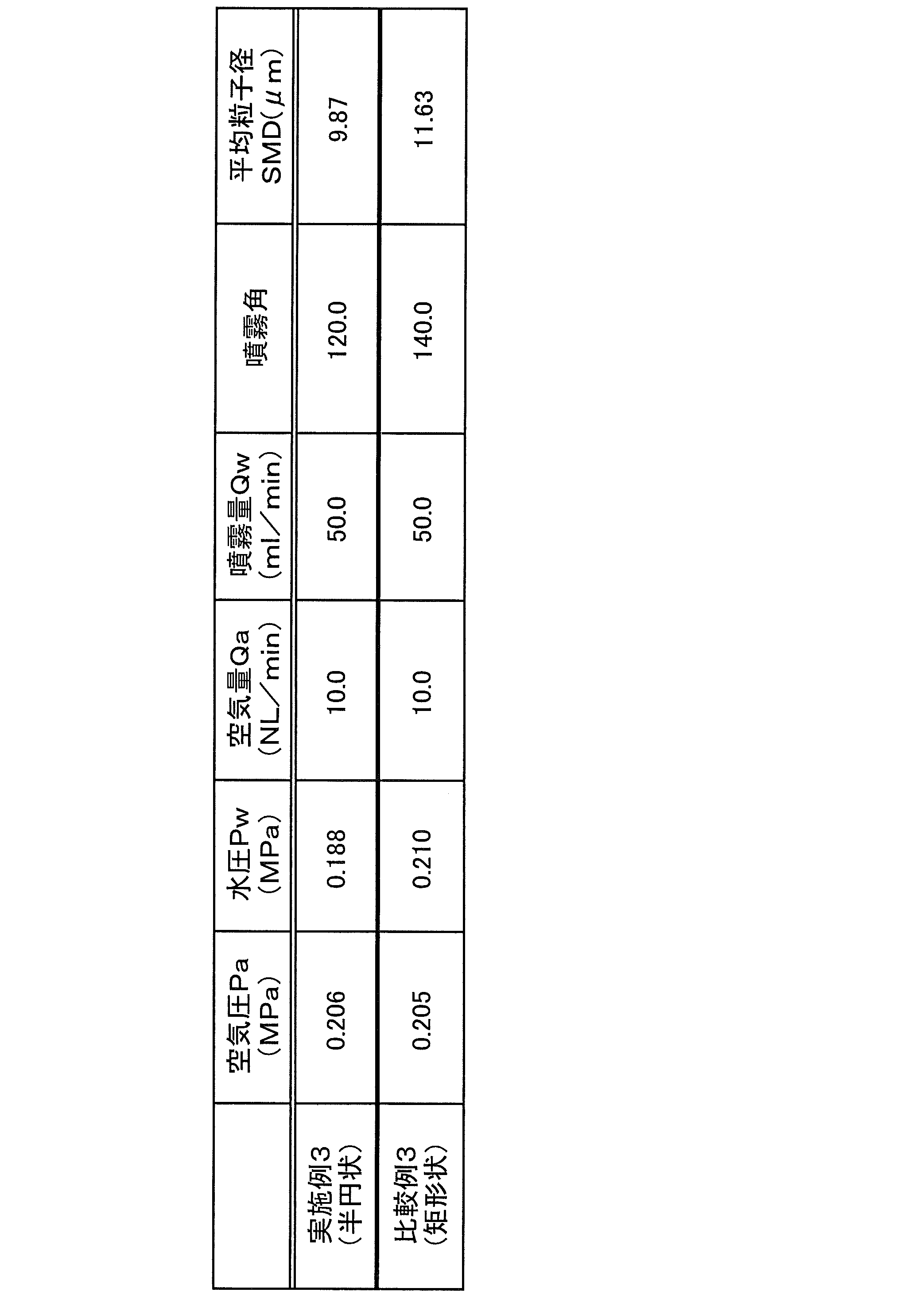
(実施例3:スプレーパターンの密度分布の評価)
実施例1は、突出部851の先端面851bが半円状になっている(実施例3として表3に記載した)。この比較として、その先端が角張っている断面矩形状の突出部について評価した(比較例3)。その結果を表3に示す。実施例3では、スプレーパターンの長径方向において、霧粒子の密度分布が略均一になっていたことを確認できた。一方、比較例3では、スプレーパターンの長径方向において、図2Dのように霧粒子の高密度のエリアと低密度のエリアとが分かれて確認できた。 (Example 3: Evaluation of spray pattern density distribution)
In Example 1, thetip end face 851b of the protrusion 851 is semicircular (described in Table 3 as Example 3). As this comparison, a projecting portion having a rectangular cross section with an angular tip was evaluated (Comparative Example 3). The results are shown in Table 3. In Example 3, it was confirmed that the density distribution of the fog particles was substantially uniform in the major axis direction of the spray pattern. On the other hand, in Comparative Example 3, in the major axis direction of the spray pattern, as shown in FIG. 2D, the high-density area and the low-density area of the mist particles were confirmed separately.
実施例1は、突出部851の先端面851bが半円状になっている(実施例3として表3に記載した)。この比較として、その先端が角張っている断面矩形状の突出部について評価した(比較例3)。その結果を表3に示す。実施例3では、スプレーパターンの長径方向において、霧粒子の密度分布が略均一になっていたことを確認できた。一方、比較例3では、スプレーパターンの長径方向において、図2Dのように霧粒子の高密度のエリアと低密度のエリアとが分かれて確認できた。 (Example 3: Evaluation of spray pattern density distribution)
In Example 1, the
(実施例4)
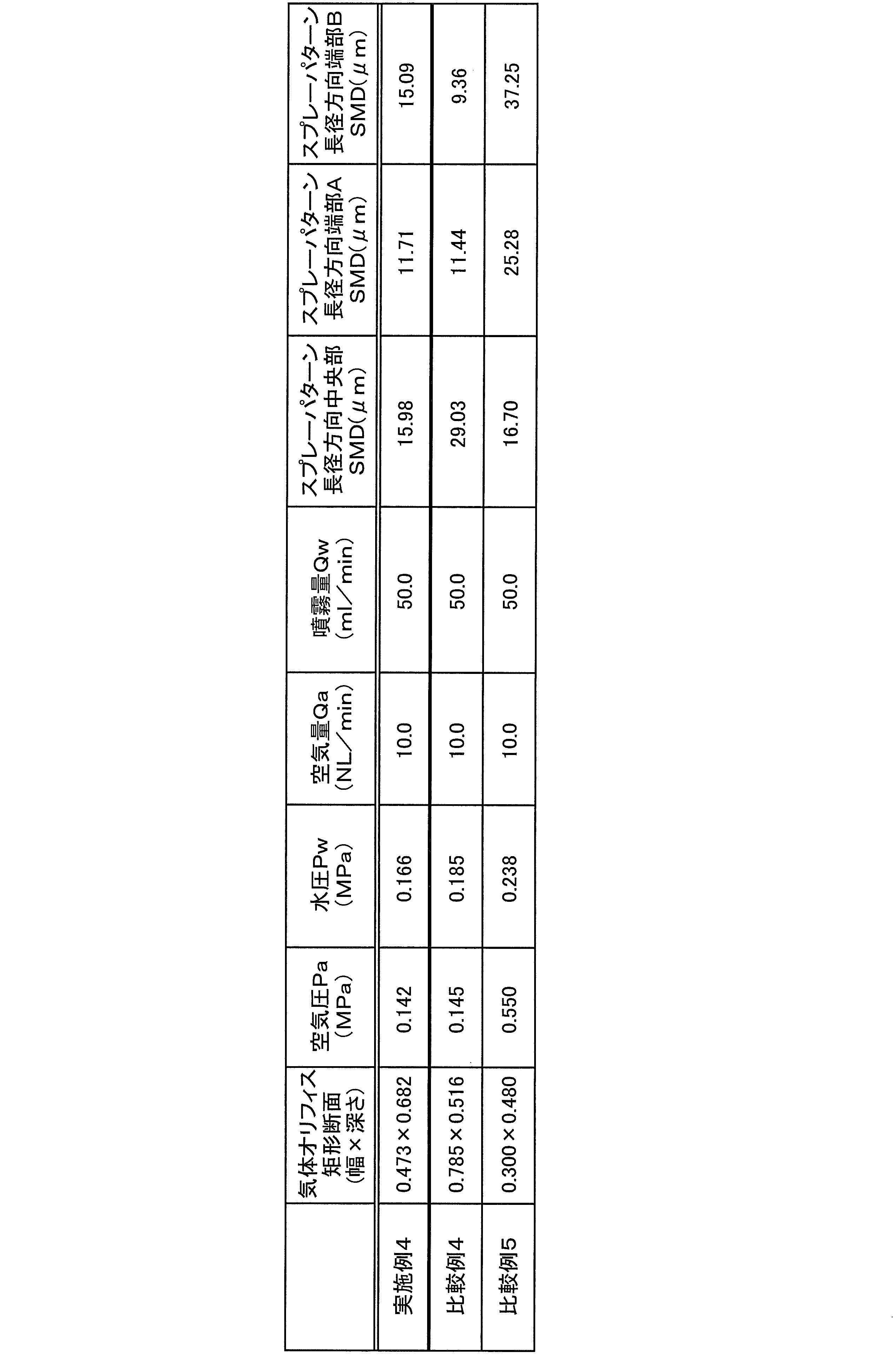
次に、液体オリフィス先端直径をφ=0.35mmに固定し、気体オリフィスの矩形断面サイズを変えて、気体噴射の空気量Qaを10.0(NL/min)、噴霧(水)量Qwを50.0(ml/min)とした場合の空気圧Pa、水圧Pw、スプレーパターンの長径方向の中央部および両端部A,Bの平均粒子径(SMD)を評価した(比較例4,5)。その結果を表4に示す。実施例4(スリット幅が液体オリフィス先端直径の1.35倍)では、スプレーパターンの長径方向において、中央部、両端部A,Bが略均一の粒子径であり、略均一の微細化であった。一方、比較例4(気体オリフィスの矩形断面サイズが過大、スリット幅が液体オリフィス先端直径の2.24倍)では、スプレーパターンの長径方向において、中央部の平均粒子径が両端部のそれよりも2倍以上であり、液体の微細化効果が低くかった。これは、空気量と噴霧量とを一定条件にして行ったため、2つの気体流の衝突壁における空気密度が実施例4よりも低く、液体の微細化が進む前に前方へ噴霧されてしまったと推測される。また、比較例5(気体オリフィスの矩形断面サイズが過小、スリット幅が液体オリフィス先端直径の0.85倍)では、スプレーパターンの長径方向において、中央部の平均粒子径が両端部のそれよりも2倍程度小さく、液体の微細化効果が低くかった。これは、2つの気体流の衝突壁よりもこれと衝突する液体の断面積が大きいため、液体流の径方向にいく程、気体流との衝突が少なかったものと推測される。 (Example 4)
Next, the diameter of the liquid orifice tip is fixed to φ = 0.35 mm, the rectangular cross-sectional size of the gas orifice is changed, the air quantity Qa of gas injection is 10.0 (NL / min), and the spray (water) quantity Qw is In the case of 50.0 (ml / min), the air pressure Pa, the water pressure Pw, and the average particle diameter (SMD) of the central part and both end parts A and B in the major axis direction of the spray pattern were evaluated (Comparative Examples 4 and 5). The results are shown in Table 4. In Example 4 (the slit width is 1.35 times the diameter of the tip of the liquid orifice), the central portion and both end portions A and B have substantially uniform particle diameters in the major axis direction of the spray pattern. It was. On the other hand, in Comparative Example 4 (the rectangular cross-sectional size of the gas orifice is excessive and the slit width is 2.24 times the diameter of the tip of the liquid orifice), the average particle diameter in the central portion is larger than that at both ends in the major axis direction of the spray pattern. It was 2 times or more, and the effect of refining the liquid was low. This was done with the air amount and the spray amount being constant, so that the air density at the collision wall of the two gas flows was lower than in Example 4 and sprayed forward before the liquid miniaturization progressed. Guessed. Further, in Comparative Example 5 (the rectangular cross-sectional size of the gas orifice is too small and the slit width is 0.85 times the tip diameter of the liquid orifice), the average particle diameter in the central portion is larger than that at both end portions in the major axis direction of the spray pattern. About twice as small, the effect of liquid miniaturization was low. This is presumed that since the cross-sectional area of the liquid colliding with the collision wall of the two gas flows is larger than the collision wall of the two gas flows, the collision with the gas flow is less as the liquid flow is in the radial direction.
なお、上記において、平均粒子径(SMD)はレーザー回折法の計測装置により測定した。測定位置は、噴霧方向軸上で、ノズル先端から150mmの位置とした。
In the above, the average particle size (SMD) was measured with a laser diffraction measuring device. The measurement position was 150 mm from the nozzle tip on the spray direction axis.
1 第1気体噴射部(第1気体オリフィス)
2 第2気体噴射部(第2気体オリフィス)
6 液体流出部(液体オリフィス)
30 突出部
31 噴出用スリット部
32a、32b 規制部
62 霧
81 第1気体オリフィス
85 外側キャップ部
851 突出部
851a 噴出用スリット部
851b 先端断面
852a、852b 規制部
91 液体オリフィス
100 衝突部
100a 衝突面
120 気液混合エリア 1 1st gas injection part (1st gas orifice)
2 Second gas injection part (second gas orifice)
6 Liquid outflow part (liquid orifice)
30Protruding part 31 Ejecting slit part 32a, 32b Restricting part 62 Fog 81 First gas orifice 85 Outer cap part 851 Protruding part 851a Ejecting slit part 851b Tip section 852a, 852b Restricting part 91 Liquid orifice 100 Colliding part 100a Colliding surface 120 Gas-liquid mixing area
2 第2気体噴射部(第2気体オリフィス)
6 液体流出部(液体オリフィス)
30 突出部
31 噴出用スリット部
32a、32b 規制部
62 霧
81 第1気体オリフィス
85 外側キャップ部
851 突出部
851a 噴出用スリット部
851b 先端断面
852a、852b 規制部
91 液体オリフィス
100 衝突部
100a 衝突面
120 気液混合エリア 1 1st gas injection part (1st gas orifice)
2 Second gas injection part (second gas orifice)
6 Liquid outflow part (liquid orifice)
30
Claims (5)
- 2つの気体流同士を衝突させるための第1気体噴射部および第2気体噴射部と、
液体を流出させるための液体流出部と、
前記第1気体噴射部から噴射された気体流と前記第2気体噴射部から噴射された気体流と前記液体流出部から流出した液体とを衝突させて当該液体を霧化させるエリアである気液混合エリア部と、
装置外側に断面凸状に突出して形成され、内部に前記気液混合エリア部が形成される突出部と、
前記突出部に、前記気液混合エリア部で生成された霧の広角噴霧方向に沿って形成される噴出用スリット部と、
前記噴出用スリット部の底部近傍に、前記霧の広角噴霧方向に向かって傾斜して形成される規制部と、を備える液体霧化装置。 A first gas injection unit and a second gas injection unit for causing two gas flows to collide with each other;
A liquid outflow part for flowing out the liquid;
The gas-liquid is an area in which the gas flow injected from the first gas injection unit, the gas flow injected from the second gas injection unit, and the liquid flowing out from the liquid outflow unit collide with each other to atomize the liquid. A mixing area,
A projecting portion that is formed so as to protrude in a cross-sectional convex shape on the outside of the device, and in which the gas-liquid mixing area portion is formed;
The ejection slit portion formed along the wide-angle spray direction of the mist generated in the gas-liquid mixing area portion on the protruding portion,
A liquid atomizing device comprising: a regulating portion formed near the bottom of the ejection slit portion and inclined toward the wide-angle spraying direction of the mist. - 前記規制部は、20°~150°の角度範囲で傾斜して形成される、請求項1に記載の液体霧化装置。 2. The liquid atomizing apparatus according to claim 1, wherein the restricting portion is formed to be inclined within an angle range of 20 ° to 150 °.
- 前記気液混合エリアが、前記噴出用スリット部の底部よりも噴霧方向側に形成される、請求項1または2に記載の液体霧化装置。 The liquid atomization apparatus according to claim 1 or 2, wherein the gas-liquid mixing area is formed on a spraying direction side with respect to a bottom portion of the ejection slit portion.
- 前記突出部の装置外部に突出している先端部断面が、半円形状または半楕円形状である、請求項1~3のいずれか1項に記載の液体霧化装置。 The liquid atomizing device according to any one of claims 1 to 3, wherein a cross-section of a tip portion of the protruding portion protruding outside the device has a semicircular shape or a semi-elliptical shape.
- 前記第1気体噴射部のスリット幅(d1)および前記第2気体噴射部のスリット幅(d2)が、前記液体流出部の出口オリフィス直径(d3)の1倍~1.5倍である、請求項1~4のいずれか1項に記載の液体霧化装置。 The slit width (d1) of the first gas injection unit and the slit width (d2) of the second gas injection unit are 1 to 1.5 times the outlet orifice diameter (d3) of the liquid outflow unit. Item 5. The liquid atomizing apparatus according to any one of Items 1 to 4.
Priority Applications (3)
| Application Number | Priority Date | Filing Date | Title |
|---|---|---|---|
| CN201280065761.4A CN104023853A (en) | 2011-11-02 | 2012-10-19 | Liquid atomizing device |
| US14/355,823 US20150035179A1 (en) | 2011-11-02 | 2012-10-19 | Liquid atomization device |
| EP12846375.9A EP2801412A4 (en) | 2011-11-02 | 2012-10-19 | Liquid atomization device |
Applications Claiming Priority (2)
| Application Number | Priority Date | Filing Date | Title |
|---|---|---|---|
| JP2011-241330 | 2011-11-02 | ||
| JP2011241330A JP5971640B2 (en) | 2011-11-02 | 2011-11-02 | Liquid atomizer |
Publications (1)
| Publication Number | Publication Date |
|---|---|
| WO2013065503A1 true WO2013065503A1 (en) | 2013-05-10 |
Family
ID=48191858
Family Applications (1)
| Application Number | Title | Priority Date | Filing Date |
|---|---|---|---|
| PCT/JP2012/077075 WO2013065503A1 (en) | 2011-11-02 | 2012-10-19 | Liquid atomization device |
Country Status (6)
| Country | Link |
|---|---|
| US (1) | US20150035179A1 (en) |
| EP (1) | EP2801412A4 (en) |
| JP (1) | JP5971640B2 (en) |
| CN (1) | CN104023853A (en) |
| TW (1) | TW201330934A (en) |
| WO (1) | WO2013065503A1 (en) |
Cited By (1)
| Publication number | Priority date | Publication date | Assignee | Title |
|---|---|---|---|---|
| EP3154613B1 (en) * | 2014-06-16 | 2020-05-13 | Meway Pharma Ltd | A novel operated nebulizer and means thereof |
Families Citing this family (3)
| Publication number | Priority date | Publication date | Assignee | Title |
|---|---|---|---|---|
| FR3086513B1 (en) * | 2018-10-02 | 2021-10-15 | Oreal | COSMETIC TREATMENT PROCESS |
| FR3086514B1 (en) * | 2018-10-02 | 2021-10-15 | Oreal | HAIR COLORING PROCESS |
| JP7001789B2 (en) * | 2020-10-23 | 2022-01-20 | リンナイ株式会社 | Gas supply manifold |
Citations (7)
| Publication number | Priority date | Publication date | Assignee | Title |
|---|---|---|---|---|
| JPH04122658U (en) * | 1991-04-15 | 1992-11-04 | アロイ工器株式会社 | Fan-shaped spray nozzle |
| WO2001002099A1 (en) * | 1999-06-30 | 2001-01-11 | Anest Iwata Corporation | Low-pressure atomizing spray gun |
| JP2002010942A (en) * | 2000-06-29 | 2002-01-15 | Matsushita Electric Ind Co Ltd | Shower device |
| JP2002126587A (en) | 2000-10-19 | 2002-05-08 | Bio Media Co Ltd | Spray nozzle device |
| JP2006167601A (en) * | 2004-12-16 | 2006-06-29 | Ikeuchi:Kk | Two-fluid nozzle |
| JP2008296197A (en) * | 2007-06-04 | 2008-12-11 | Jfe Steel Kk | Nozzle |
| JP2011212649A (en) * | 2010-03-15 | 2011-10-27 | Nozzle Network Co Ltd | Two-fluid nozzle and atomizing device provided with two-fluid nozzle |
Family Cites Families (10)
| Publication number | Priority date | Publication date | Assignee | Title |
|---|---|---|---|---|
| US2774631A (en) * | 1952-06-11 | 1956-12-18 | Spraying Systems Co | Two-part orifice spray nozzle and method of making same |
| JPS6079563U (en) * | 1983-11-02 | 1985-06-03 | 株式会社いけうち | spray nozzle |
| JPS6227058A (en) * | 1985-07-25 | 1987-02-05 | Kawasaki Steel Corp | Molten metal atomizer |
| US5115972A (en) * | 1991-02-06 | 1992-05-26 | Minnesota Mining And Manufacturing Company | Spray die for producing spray fans |
| US6267301B1 (en) * | 1999-06-11 | 2001-07-31 | Spraying Systems Co. | Air atomizing nozzle assembly with improved air cap |
| US6161778A (en) * | 1999-06-11 | 2000-12-19 | Spraying Systems Co. | Air atomizing nozzle assembly with improved air cap |
| DE10009573B4 (en) * | 2000-02-29 | 2006-01-26 | Mabo Steuerungselemente Vertriebs-Gmbh | Nozzle device, in particular arranged in sanitary basins and containers |
| US8684281B2 (en) * | 2006-03-24 | 2014-04-01 | Finishing Brands Holdings Inc. | Spray device having removable hard coated tip |
| JP3152114U (en) * | 2009-02-09 | 2009-07-23 | 大起理化工業株式会社 | Small-diameter rainfall generator |
| US8524312B2 (en) * | 2011-11-16 | 2013-09-03 | Csl Silicones Inc. | Applicator for spraying elastomeric materials |
-
2011
- 2011-11-02 JP JP2011241330A patent/JP5971640B2/en active Active
-
2012
- 2012-10-19 CN CN201280065761.4A patent/CN104023853A/en active Pending
- 2012-10-19 US US14/355,823 patent/US20150035179A1/en not_active Abandoned
- 2012-10-19 WO PCT/JP2012/077075 patent/WO2013065503A1/en active Application Filing
- 2012-10-19 EP EP12846375.9A patent/EP2801412A4/en not_active Withdrawn
- 2012-10-24 TW TW101139234A patent/TW201330934A/en unknown
Patent Citations (7)
| Publication number | Priority date | Publication date | Assignee | Title |
|---|---|---|---|---|
| JPH04122658U (en) * | 1991-04-15 | 1992-11-04 | アロイ工器株式会社 | Fan-shaped spray nozzle |
| WO2001002099A1 (en) * | 1999-06-30 | 2001-01-11 | Anest Iwata Corporation | Low-pressure atomizing spray gun |
| JP2002010942A (en) * | 2000-06-29 | 2002-01-15 | Matsushita Electric Ind Co Ltd | Shower device |
| JP2002126587A (en) | 2000-10-19 | 2002-05-08 | Bio Media Co Ltd | Spray nozzle device |
| JP2006167601A (en) * | 2004-12-16 | 2006-06-29 | Ikeuchi:Kk | Two-fluid nozzle |
| JP2008296197A (en) * | 2007-06-04 | 2008-12-11 | Jfe Steel Kk | Nozzle |
| JP2011212649A (en) * | 2010-03-15 | 2011-10-27 | Nozzle Network Co Ltd | Two-fluid nozzle and atomizing device provided with two-fluid nozzle |
Non-Patent Citations (1)
| Title |
|---|
| See also references of EP2801412A4 |
Cited By (2)
| Publication number | Priority date | Publication date | Assignee | Title |
|---|---|---|---|---|
| EP3154613B1 (en) * | 2014-06-16 | 2020-05-13 | Meway Pharma Ltd | A novel operated nebulizer and means thereof |
| US11020542B2 (en) | 2014-06-16 | 2021-06-01 | Sanara Tech Ltd. | Operated nebulizer and means thereof |
Also Published As
| Publication number | Publication date |
|---|---|
| EP2801412A1 (en) | 2014-11-12 |
| TW201330934A (en) | 2013-08-01 |
| EP2801412A4 (en) | 2015-03-25 |
| US20150035179A1 (en) | 2015-02-05 |
| JP2013094749A (en) | 2013-05-20 |
| JP5971640B2 (en) | 2016-08-17 |
| CN104023853A (en) | 2014-09-03 |
Similar Documents
| Publication | Publication Date | Title |
|---|---|---|
| US8104697B2 (en) | Fluid spray control device | |
| CN106163672B (en) | Improved swozzle assembly with high efficiency mechanical break-up for producing uniform small droplet spray | |
| WO2013094522A1 (en) | Liquid atomization device | |
| WO2013065503A1 (en) | Liquid atomization device | |
| JPH08229463A (en) | Nozzle assembly for foaming equipment | |
| US20190015855A1 (en) | Nozzles and methods of mixing fluid flows | |
| RU2647104C2 (en) | Finely divided liquid sprayer | |
| JP5672613B2 (en) | Liquid atomizer | |
| JPH09220495A (en) | Fluid injection nozzle | |
| JPWO2013146624A1 (en) | Liquid ejecting apparatus and liquid ejecting method | |
| JP5140712B2 (en) | Liquid atomization apparatus and liquid atomization method | |
| JP2019018183A (en) | Two-fluid nozzle | |
| RU2551063C1 (en) | Fluid sprayer | |
| JP6814993B2 (en) | Sprayer | |
| JP4778212B2 (en) | Three fluid nozzle | |
| JP3563067B2 (en) | Method and apparatus for atomizing liquid | |
| JP2013193006A (en) | Liquid atomization apparatus | |
| WO2013073336A1 (en) | Liquid atomization device | |
| JP2012254457A (en) | Liquid atomizing device and liquid atomizing method | |
| JP2003117442A (en) | Method for atomizing liquid and nozzle used for the same | |
| JP2023174199A (en) | spray device | |
| JP2004344689A (en) | Two-fluid nozzle | |
| JP2000246153A (en) | Powder atomizing device | |
| JP2023175228A (en) | Binary fluid spray device | |
| JP2013180258A (en) | Liquid atomizing device |
Legal Events
| Date | Code | Title | Description |
|---|---|---|---|
| 121 | Ep: the epo has been informed by wipo that ep was designated in this application |
Ref document number: 12846375 Country of ref document: EP Kind code of ref document: A1 |
|
| NENP | Non-entry into the national phase |
Ref country code: DE |
|
| WWE | Wipo information: entry into national phase |
Ref document number: 14355823 Country of ref document: US |
|
| WWE | Wipo information: entry into national phase |
Ref document number: 2012846375 Country of ref document: EP |