WO2013065147A1 - Electrocardiograph and bioelectrode pad - Google Patents
Electrocardiograph and bioelectrode pad Download PDFInfo
- Publication number
- WO2013065147A1 WO2013065147A1 PCT/JP2011/075313 JP2011075313W WO2013065147A1 WO 2013065147 A1 WO2013065147 A1 WO 2013065147A1 JP 2011075313 W JP2011075313 W JP 2011075313W WO 2013065147 A1 WO2013065147 A1 WO 2013065147A1
- Authority
- WO
- WIPO (PCT)
- Prior art keywords
- electrodes
- electrode
- conductive gel
- signal
- electrocardiograph
- Prior art date
Links
Images


Classifications
-
- A—HUMAN NECESSITIES
- A61—MEDICAL OR VETERINARY SCIENCE; HYGIENE
- A61B—DIAGNOSIS; SURGERY; IDENTIFICATION
- A61B5/00—Measuring for diagnostic purposes; Identification of persons
- A61B5/24—Detecting, measuring or recording bioelectric or biomagnetic signals of the body or parts thereof
- A61B5/25—Bioelectric electrodes therefor
- A61B5/279—Bioelectric electrodes therefor specially adapted for particular uses
- A61B5/28—Bioelectric electrodes therefor specially adapted for particular uses for electrocardiography [ECG]
- A61B5/282—Holders for multiple electrodes
-
- A—HUMAN NECESSITIES
- A61—MEDICAL OR VETERINARY SCIENCE; HYGIENE
- A61B—DIAGNOSIS; SURGERY; IDENTIFICATION
- A61B5/00—Measuring for diagnostic purposes; Identification of persons
- A61B5/24—Detecting, measuring or recording bioelectric or biomagnetic signals of the body or parts thereof
- A61B5/30—Input circuits therefor
-
- A—HUMAN NECESSITIES
- A61—MEDICAL OR VETERINARY SCIENCE; HYGIENE
- A61B—DIAGNOSIS; SURGERY; IDENTIFICATION
- A61B5/00—Measuring for diagnostic purposes; Identification of persons
- A61B5/24—Detecting, measuring or recording bioelectric or biomagnetic signals of the body or parts thereof
- A61B5/25—Bioelectric electrodes therefor
- A61B5/251—Means for maintaining electrode contact with the body
- A61B5/257—Means for maintaining electrode contact with the body using adhesive means, e.g. adhesive pads or tapes
- A61B5/259—Means for maintaining electrode contact with the body using adhesive means, e.g. adhesive pads or tapes using conductive adhesive means, e.g. gels
-
- A—HUMAN NECESSITIES
- A61—MEDICAL OR VETERINARY SCIENCE; HYGIENE
- A61B—DIAGNOSIS; SURGERY; IDENTIFICATION
- A61B5/00—Measuring for diagnostic purposes; Identification of persons
- A61B5/72—Signal processing specially adapted for physiological signals or for diagnostic purposes
- A61B5/7203—Signal processing specially adapted for physiological signals or for diagnostic purposes for noise prevention, reduction or removal
- A61B5/7207—Signal processing specially adapted for physiological signals or for diagnostic purposes for noise prevention, reduction or removal of noise induced by motion artifacts
- A61B5/7214—Signal processing specially adapted for physiological signals or for diagnostic purposes for noise prevention, reduction or removal of noise induced by motion artifacts using signal cancellation, e.g. based on input of two identical physiological sensors spaced apart, or based on two signals derived from the same sensor, for different optical wavelengths
-
- A—HUMAN NECESSITIES
- A61—MEDICAL OR VETERINARY SCIENCE; HYGIENE
- A61B—DIAGNOSIS; SURGERY; IDENTIFICATION
- A61B2562/00—Details of sensors; Constructional details of sensor housings or probes; Accessories for sensors
- A61B2562/12—Manufacturing methods specially adapted for producing sensors for in-vivo measurements
- A61B2562/125—Manufacturing methods specially adapted for producing sensors for in-vivo measurements characterised by the manufacture of electrodes
Definitions
- the present invention relates to an electrocardiogram and a biomedical electrode pad used for the electrocardiograph and mounted on the skin of a living body to measure an electrocardiogram signal, and in particular to electrocardiogram without being disturbed by body motion noise.
- the present invention relates to an electrocardiograph and biomedical electrode pad which can stably measure the
- the electrocardiographs are each formed on the skin surface of a predetermined part of a living body.
- the electrode pads are brought into contact with the skin surface of the living body to obtain the difference between the signals from any one of the electrode pads.
- the body movement noise signal is obtained by taking the difference between the signal from the electrode having a relatively small area and the electrode having a relatively large area for each of the electrode pads.
- the body movement noise signal is generated by the fluctuation of the polarization potential or impedance generated between the electrode and the conductive gel and between the conductive gel and the skin surface due to body movement.
- the present invention advantageously solves the problems of the conventional electrocardiograph and biomedical electrode pad in view of the above-mentioned points, and the electrocardiograph of the present invention is used for a plurality of biomedicals attached to the skin of a living organism.
- an electrocardiograph which processes an electrical signal detected using an electrode pad and measures an electrocardiogram signal
- a plurality of electrodes in which the plurality of biomedical electrode pads are respectively stacked and arranged, and the plurality of electrodes
- an electroconductive gel sheet alternately disposed between the electrodes
- the electrocardiograph comprises any one of two biomedical electrode pads of the plurality of biomedical electrode pads.
- body movement Second to determine the noise signal And minutes circuit is characterized in that it comprises a body motion noise removing circuit for removing from the original electrocardiogram signal a low-frequency component of each body motion noise signal of the two biomedical electrode pads.
- the biomedical electrode pad in the biomedical electrode pad for the electrocardiograph, a plurality of electrodes stacked and disposed alternately with the plurality of electrodes alternately disposed between the electrodes And a conductive gel sheet interposed therebetween.
- the plurality of electrodes of the biomedical electrode pad are held against the skin surface in a mutually overlapping state.
- conductive gel sheets are interposed between the electrodes, they are connected in series with each other, and signals are detected and output in sufficient areas, respectively.
- the voltage of the signal output from the electrode sandwiched between the electrode and the skin is a predetermined voltage determined by the number of the electrodes and the conductive gel sheet relative to the voltage of the signal output from the outer electrode opposite to the skin side. It will decrease at a rate.
- the outer electrode opposite to the skin side is used as a body movement noise detection electrode and the electrode sandwiched between the electrode and the skin is an original electrocardiogram signal detection electrode
- the outer electrode opposite to the skin side is used as an original electrocardiogram signal detection electrode and the electrode sandwiched between the electrode and the skin is used as a body movement noise detection electrode.
- a sufficient level of body movement noise signal and electrocardiogram signal can be detected, and the signal from the electrode sandwiched between the electrode and the skin is output from the electrode on the outer side opposite to the skin side It can be assumed that the voltage decreases at a predetermined rate determined by the number of electrodes and the number of conductive gel sheets.
- the electrocardiograph of the present invention using the biomedical electrode pad of the present invention, it is possible to obtain sufficient levels of body movement noise signal and original electrocardiogram signal as described above, and body movement.
- the amplification factor of noise and an original electrocardiogram signal can be easily set, and the influence of body movement can be sufficiently eliminated from the electrocardiogram signal.
- each of the two biomedical electrode pads has three electrodes stacked one on another, and the first differential circuit is one of the three electrodes.
- the difference between the signals from the electrodes located in the middle is calculated to obtain an original electrocardiogram signal, and the second difference circuit calculates the difference between the signals from the electrodes located on both outer sides of the three electrodes. It is preferable to determine the motion noise signal.
- the voltage of the body movement noise signal is between those electrodes. It will be detected, and since the original electrocardiogram signal and voltage of 1/2 level of body movement noise signal will be detected in the electrode located in the middle, it is detected in the electrode located in the middle Body movement noise signals can all be detected by the electrodes located on both sides, so that body movement noise signals can be effectively eliminated from the original electrocardiogram signal for each living body electrode pad.
- the biomedical electrode pad according to the present invention it is preferable to further include a conductive gel sheet laminated and disposed outside the plurality of electrodes on the skin side in the stacking direction of the plurality of electrodes.
- the conductive gel sheet intervenes between the electrode closest to the skin surface and the skin surface, body movement noise signals can be detected even at the electrode closest to the skin surface, and the electrodes are conductive. It can be covered with a gel sheet.
- At least the electrode sandwiched by the conductive gel sheet among the plurality of electrodes be a mesh or a porous one such as a cloth.
- the conductive gel penetrates the reticulated or porous electrode so that the characteristics of the conductive gel sheet on both sides of the electrode become uniform, so that in the electrocardiograph the amplification factor of body motion noise and an electrocardiogram signal
- the setting can be easily performed, and the contact area between the electrode and the conductive gel sheet is increased as compared with the flat electrode, and the electrode deforms flexibly along the skin surface.
- the detection level can be increased.
- the intermediate portion is stacked on the outer side of the electrode opposite to the skin side in the stacking direction of the plurality of electrodes, and holds the electrode and the conductive gel sheet in a stacked state.
- the intermediate portion, the electrode and the conductive gel sheet located outside in the extending direction of the plurality of electrodes and having an adhesive surface, the electrode held by the intermediate portion and the conductive It is preferable to further comprise a mounting sheet having a gel sheet and an end for mounting the gel sheet on the skin surface of a predetermined part of the living body.
- the electrodes and the conductive gel sheet are held in a stacked state at the middle portion of the mounting sheet stacked on the outside of the electrode opposite to the skin side in the stacking direction of the plurality of electrodes.
- the electrode held by the intermediate portion and the conductive gel sheet are attached to the skin surface of a predetermined part of the living body at the end portion located on the outside of the electrode and the conductive gel sheet and having the adhesive surface in the extension direction of the electrode Therefore, the electrode and the conductive gel sheet can be reliably maintained on the skin surface of a predetermined part of the living body in a laminated state.
- (A) And (b) is sectional drawing and the partially cutaway perspective view which show one Example of the biological electrode pad of this invention. It is a block diagram which shows the structure of one Example of the electrocardiograph of this invention using the biomedical electrode pad of the said Example.
- (A) is explanatory drawing which simplifies and shows the structure of the biological electrode pad of the said Example
- (b) is explanatory drawing which shows an effect
- (A) And (b) is a partially cutaway perspective view and sectional drawing which show one modification of the biological electrode pad of the said Example. It is sectional drawing which shows another one Example of the biomedical electrode pad of this invention.
- FIGS. 1 (a) and 1 (b) are a sectional view and a partially cutaway perspective view showing one embodiment of the biomedical electrode pad of the present invention.
- the biomedical electrode pad of this embodiment is alternately arranged with two electrodes 1 and 2 stacked on each other and the two electrodes 1 and 2 alternately.
- Two conductive gel sheets 3 and 4 interposed on the outer side (lower side in the figure) of the electrode 2 between two and on the skin side, and two sheets on the opposite side of the skin side in the stacking direction of the two electrodes 1 and 2
- the dynamic pressure stabilizing plate 5 is disposed laminated on the outside (upper side in the figure) of the electrodes 1 and 2, and the dynamic pressure stabilizing plate 5, the electrodes 1 and 2, and the conductive gel sheets 3 and 4 are laminated.
- the mounting sheet 6 is made of a normal non-conductive material and has a generally circular shape and has the adhesive material layer 6a on the entire back surface (bottom surface in the drawing), and in the stacking direction of the two electrodes 1 and 2
- the dynamic pressure stabilizing plate 5 on the side opposite to the skin side is laminated and arranged on the outer side (the upper side in the figure), and the dynamic pressure stabilizing plate 5, the electrodes 1 and 2, and the conductive gel sheets 3 and 4 are held in a laminated state by the adhesive material layer 6 a And the dynamic pressure stabilizing plate 5, the electrodes 1, 2 and the conductive gel sheets 3, 4 in the extending direction of the two electrodes 1, 2 (horizontal direction in the figure).
- the conductive gel sheet 3 intervenes between the electrode 1 and the electrode 2, the generation noise of the conductive gel due to the body movement is large, so it is used as a body movement noise signal detection electrode.
- an electrocardiogram signal detection electrode because it is smaller than 1, it is preferable to use the electrode 1 as an electrocardiogram signal detection electrode and also use the electrode 2 as a body movement noise signal detection electrode. It is possible to detect
- the dynamic pressure stabilizer 5 is generally formed of, for example, a plastic base material and has a substantially disc shape.
- the electrode 1 as a whole is formed of, for example, a plastic base material to have a substantially flat plate shape, and has the connection terminal 1a protruding from the upper surface thereof, and the flat plate portion and the surface of the connection terminal 1a are good.
- the shaft of the connection terminal 1a of the electrode 1 is covered with an insulating coating on the outer peripheral surface, and the tip of the connection terminal 1a is a through hole of the dynamic pressure stabilizing plate 5 and a conductive metal.
- the through-hole of the intermediate portion 6 b of the mounting sheet 6 is inserted from the back side and protrudes to the front side of the mounting sheet 6.
- the electrode 2 as a whole is formed of, for example, a metal wire to form a netlike shape, and has a connection terminal 2a protruding from the upper surface thereof, and the netlike portion and the surface of the connection terminal 2a are metal with good conductivity
- it is coated with silver chloride plating, and the axial portion of the connection terminal 2a of the electrode 2 is coated with insulation on the outer peripheral surface, and the tip of the connection terminal 2a is made of the conductive gel sheet 3, the electrode 1 and the dynamic pressure stabilizer 5
- the through hole and the through hole of the intermediate portion 6 b of the mounting sheet 6 are inserted from the back side and protrude to the front side of the mounting sheet 6.
- the conductive gel sheets 3 and 4 are ordinary ones having a larger disc shape to the electrodes 1 and 2 and having adhesiveness, and the conductive gel sheet 3 adheres to the dynamic pressure stabilizing plate 5 at its periphery to make the electrodes 1
- the conductive gel sheet 4 adheres to the conductive gel sheet 3 at its peripheral portion so as to sandwich the electrode 2 between the conductive gel sheet 3 and the conductive gel sheet 3.
- the biomedical electrode pad of this embodiment covers and protects the whole of the adhesive material layer 6a at the outer peripheral end 6c of the mounting sheet 6 and the outer side conductive gel sheet 4 when the electrode pad is not used.
- a release sheet (not shown) made of a normal film which has been surface-treated so as to be easily peeled off from the adhesive material layer 6 a and the conductive gel sheet 4 is provided.
- FIG. 2 is a block diagram showing the configuration of an embodiment of the electrocardiograph of the present invention using the biomedical electrode pad of the above embodiment, and the electrocardiograph of this embodiment is shown in FIG.
- a first difference as a first difference circuit, which takes the difference between the signals from the respective electrodes 2 of the two living body electrode pads of the above embodiment and amplifies it and outputs it as an original electrocardiogram signal.
- the difference between the signals from the electrode 1 and the electrode 2 is taken and amplified, and this is output as the motion noise signal
- the second difference The low frequency components of the body movement noise signal of each of the two biological electrode pads output from the second differential amplifiers 12 and 13 as a circuit and the two second differential amplifiers 12 and 13 are extracted.
- Two low pass filters eg Body movement noise consisting of two differential amplifiers 16 and 17 that amplify and output ones with an off frequency of 40 Hz 14 and 15 and low frequency components of their movement noise signal removed from the above-mentioned electrocardiogram signal respectively And a removal circuit.
- the biological electrode pad of the above embodiment when the biological electrode pad is attached to the skin surface S of a predetermined part of the living body, as shown in FIG. 3 (b).
- the two electrodes 1 and 2 of the electrode pad are pressed against the skin surface S by the dynamic pressure stabilizer 5 in a state where they overlap each other, and between the electrodes 1 and 2 and the electrode 2 and the skin surface S Since the conductive gel sheets 3 and 4 intervene between the two, the two electrodes 1 and 2 are connected in series with each other, and signals are detected and output with sufficient areas, respectively.
- the voltage VN of the body movement noise signal output by the electrode 2 sandwiched between the electrodes 1 and 2 and the conduction here with respect to the voltage 2VN of the body movement noise signal output by the outermost electrode 1 The ratio becomes a predetermined ratio determined by the number of gel sheets 3 and 4, that is, 1 ⁇ 2.
- the outermost electrode 1 is used as a body movement noise detection electrode and the inner electrode 2 is used as an original electrocardiogram signal detection electrode.
- the voltage 2 VN of the body movement noise signal to be obtained may be reduced to a half, which is a predetermined ratio determined by the number of the electrodes 1 and 2 and the conductive gel sheets 3 and 4.
- the first differential amplifier 11 obtains the difference between the signals from the respective electrodes 2 of the two biomedical electrode pads of the above embodiment, thereby obtaining an original electrocardiogram signal.
- the second differential amplifiers 12 and 13 calculate the difference between the signals from the electrode 1 and the electrode 2 for each of the two biomedical electrode pads in the above embodiment as described above. Find the noise signal.
- a body movement noise removal circuit comprising two low pass filters 14 and 15 and two differential amplifiers 16 and 17 uses the low frequency component of the body movement noise signal of each of the two biomedical electrode pads of the above embodiment as the origin. It removes from the electrocardiogram and outputs an electrocardiogram signal.
- Each differential amplifier has a level adjustment circuit (not shown) on its input side so that any signal can be offset by a differential.
- the electrocardiograph of this embodiment it is possible to obtain sufficient levels of body movement noise signal and electrocardiogram signal as described above, and further, amplification of body movement noise signal and parent electrocardiogram signal
- the setting of the rate can also be easily performed to sufficiently eliminate the influence of body movement from the electrocardiogram signal.
- the conductive gel sheet 4 is disposed on the lower side of the two electrodes 1, 2 in the stacking direction of the two electrodes 1, 2. Since the conductive gel sheet 4 is also interposed between the electrode 2 closest to the skin surface S and the skin surface S, the motion noise signal voltage VN can be detected even with the electrode 2 closest to the skin surface, The electrode 2 can be covered with a conductive gel sheet 4.
- the mesh electrode 2 is electrically conductive. Since the penetration of the gel makes the characteristics of the conductive gel sheets 3 and 4 on both sides of the electrode 2 uniform, it is possible to easily set the amplification factor of body motion noise and an original electrocardiogram signal in the electrocardiograph, and Since the contact area between the electrode 2 and the conductive gel sheets 3 and 4 is increased as compared with the flat electrode and the electrode 2 is flexibly deformed along the skin surface S, the detection level of the signal is also enhanced from this point as well. Can.
- the dynamic pressure stabilizing plate 5, the electrodes 1, 2, and the conductive gel sheet are stacked on the outside of the dynamic pressure stabilizing plate 5 in the stacking direction of the two electrodes 1, 2.
- the dynamic pressure stabilizing plate 5, the electrodes 1 and 2, and the conductive gel sheet 3 in the extending direction of the electrodes 1 and 2, which are continuous with the intermediate portion 6 b holding the layers 3 and 4 in the laminated state and the intermediate portion 6 b 4, the dynamic pressure stabilizing plate 5 having the adhesive layer 6a and having the adhesive layer 6a and held by the intermediate portion 6b, the electrodes 1, 2 and the conductive gel sheets 3, 4 are attached to the skin surface S of a predetermined part of the living body Since the mounting sheet 6 having the end 6c is further provided, the dynamic pressure stabilizing plate 5, the electrodes 1, 2 and the conductive gel sheets 3, 4 are laminated on the skin surface S of a predetermined part of the living body. Can be maintained.
- FIGS. 4 (a) and 4 (b) are a partially cutaway perspective view and a cross-sectional view showing a modification of the biomedical electrode pad of the above embodiment.
- two conductive gel sheets 3, 4 are used.
- the conductive gel sheet 4 on the skin surface S side is omitted, and the electrode 2 is brought into direct contact with the skin surface S of a predetermined part of the living body, and in the other points the configuration is the same as that of the above embodiment.
- the same function and effect as those of the above-described embodiment can be obtained.
- the electrode 2 of the two electrodes 1 and 2 has a mesh shape
- the mesh electrode 2 is used.
- the contact area between the electrode 2 and the conductive gel sheet 3 is increased as compared with the flat electrode, and the electrode 2 is flexibly deformed along the skin surface S.
- the detection level of the original electrocardiogram signal can be increased.
- FIG. 5 is a cross-sectional view showing another embodiment of the biomedical electrode pad according to the present invention, in which the same parts as those of the previous embodiment are indicated by the same reference numerals.
- the biomedical electrode pad of this embodiment has a third electrode 7 laminated on the lower side of the lower conductive gel sheet 4 in the biomedical electrode pad of the previous embodiment. It differs from the biomedical electrode pad and is configured in the same manner as the previous embodiment in other points.
- the electrode 7 as a whole is formed of, for example, a metal wire to form a netlike shape, and has the connection terminal 7a protruding from the upper surface thereof, and the netlike portion and the surface of the connection terminal 7a are metal with good conductivity
- the axial portion of the connection terminal 7a of the electrode 7 is covered with an insulating coating on the outer peripheral surface, and the tip of the connection terminal 7a is moved with the conductive gel sheets 3, 4 and the electrodes 1, 2
- the through hole of the pressure stabilizer 5 and the through hole of the middle portion 6 b of the mounting sheet 6 are inserted from the back side and protrude to the front side of the mounting sheet 6.
- the electrode 7 is held in a stacked state with the other electrodes 1 and 2 by the adhesive force of the lower conductive gel sheet 4.
- FIG. 6 is a block diagram showing the configuration of another embodiment of the electrocardiograph according to the present invention using the biomedical electrode pad of the above embodiment, in which the same parts as those in the previous embodiment are shown. It shows with the same code.
- the electrodes 2 of the two living body electrode pads are connected only to the first differential amplifier 11 as a first differential circuit, and the first differential amplifier 11 is The difference between the signals from the respective electrodes 2 of the two biomedical electrode pads is taken and amplified, and this is output as an electrocardiogram signal.
- the electrodes 1 and 7 are respectively connected to the second differential amplifiers 12 and 13 as a second differential circuit, and the second differential amplifiers 12 and 13 are respectively , The difference between the signals from the electrode 1 and the electrode 7 is taken and amplified, and it is output as a body movement noise signal.
- the biological electrode pad of the above embodiment when the biological electrode pad is attached to the skin surface S of a predetermined site of the living body, as shown in FIG. 7 are pressed against the skin surface S by the dynamic pressure stabilizer 5 in a state where they overlap each other, and since the conductive gel sheets 3 and 4 are interposed between the electrodes 1 and 2 and between the electrodes 2 and 7, The three electrodes 1, 2, 7 are connected in series with each other, and the signals are detected and output with sufficient areas, respectively. As a result, the voltage VN of the body movement noise signal output from the electrode 2 sandwiched between the electrodes 2 and 3 here is different from the voltage 2VN for the body movement noise signal output from the outer electrodes 1 and 7 here. 7 and the number of conductive gel sheets 3 and 4 are reduced to a predetermined ratio, that is, 1 ⁇ 2.
- the biomedical electrode pad of this embodiment by using the outer electrodes 1 and 7 as body motion noise detection electrodes and the electrodes 2 between them as the original electrocardiogram signal detection electrodes, those electrodes 1 and 2 are obtained. 2 and 7 can detect the motion noise signal voltage VN and the electrocardiogram signal voltage VHN of sufficient levels, respectively, and the voltage VN of the motion noise signal from the electrode 2 between them can be detected by the outer electrode 1 , 7 can be reduced to 1 ⁇ 2, which is a predetermined ratio determined by the number of electrodes 1, 2, 7 and the number of conductive gel sheets 3, 4.
- the first differential amplifier 11 obtains the difference between the signals from the respective electrodes 2 of the two biomedical electrode pads of the above embodiment, thereby obtaining an original electrocardiogram signal.
- the second differential amplifiers 12 and 13 calculate the difference between the signals from the electrode 1 and the electrode 7 for each of the two biomedical electrode pads of the above embodiment as described above. Find the noise signal.
- a body movement noise removal circuit comprising two low pass filters 14 and 15 and two differential amplifiers 16 and 17 uses the low frequency component of the body movement noise signal of each of the two biomedical electrode pads of the above embodiment as the origin. It removes from the electrocardiogram and outputs an electrocardiogram signal.
- Each differential amplifier has a level adjustment circuit (not shown) on its input side so that any signal can be offset by a differential.
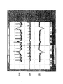
- FIG. 8 is an explanatory view showing the measurement results of the electrocardiogram signal by the electrocardiograph of the embodiment shown in FIG. 6, in which reference numeral SHN is a signal by the original electrocardiogram signal voltage VHN, and SN is a body movement noise signal voltage VN. , And SH respectively indicate signals by the electrocardiographic signal voltage VH.
- reference numeral SHN is a signal by the original electrocardiogram signal voltage VHN
- SN is a body movement noise signal voltage VN.
- SH respectively indicate signals by the electrocardiographic signal voltage VH.
- this invention is not limited to the above-mentioned example, It can change suitably within the statement range of a claim, and, in the electrode pad for living bodies of this invention, for example, The mounting sheet 6 and the release sheet may be omitted, and a laminate of the dynamic pressure stabilizing plate 5, the electrodes 1, 2 and the conductive gel sheets 3, 4 may be fixed on the skin surface S with an adhesive tape or the like. 7 may be a non-reticulated cloth-like flexible porous one, a hard porous one or a plate without holes.
- the dynamic pressure stabilizing plate 5 may be made soft, or the dynamic pressure stabilizing plate 5 may be omitted, and the electrode 1 may also be used as the dynamic pressure stabilizing plate, in which case the electrode 1 is also flexible like mesh It is good also as a thing.
- the electrode 1 may be used as an original electrocardiogram signal detection electrode and the electrode 2 may be used as a body movement noise signal detection electrode, and further connected to a ground circuit as in the conventional example.
- an indifferent electrode may be used, and a high pass filter may also be provided to remove myoelectric noise from the original electrocardiogram signal.
- the outer electrode opposite to the skin side is used as a body motion noise detection electrode and the electrode sandwiched between the electrode and the skin is used as an original electrocardiogram signal detection electrode.
- the electrode on the side opposite to the skin side is used as an original electrocardiogram signal detection electrode and the electrode sandwiched between the electrode and the skin is used as a body movement noise detection electrode.
- Noise of the body movement noise signal and the electrocardiogram signal, and the signal from the electrode sandwiched between the electrode and the skin is output from the electrode on the side opposite to the skin side.
- the voltage may be reduced at a predetermined rate determined by the number of electrodes and the number of conductive gel sheets.
- the electrocardiograph of the present invention using the biomedical electrode pad of the present invention, it is possible to obtain sufficient levels of body movement noise signal and original electrocardiogram signal as described above, and body movement.
- the amplification factor of noise and an original electrocardiogram signal can be easily set, and the influence of body movement can be sufficiently eliminated from the electrocardiogram signal.
Abstract
Description
1a,2a,7a 接続端子
3,4 導電ゲルシート
5 動圧安定板
6 装着シート
6a 粘着層
6b 中間部
6c 外周端部
11 第1の差動アンプ
12,13 第2の差動アンプ
14,15 ローパスフィルタ
16,17 差動アンプ
S 皮膚表面 1, 2, 7
Claims (6)
- 生体の皮膚に装着される複数の生体用電極パッドを用いて検出した電気信号を処理して心電信号を計測する心電計において、
前記複数の生体用電極パッドが各々、
互いに積層配置された複数枚の電極と、
前記複数枚の電極と交互に配置されてそれらの電極間に介在する導電ゲルシートと、
を具え、
前記心電計が、
前記複数の生体用電極パッドのうちの二つの生体用電極パッドのそれぞれの、何れか一つの電極からの信号同士の差分をとって原心電信号を求める第1の差分回路と、
前記二つの生体用電極パッドのそれぞれについて、何れか二つの電極からの信号同士の差分をとって体動ノイズ信号を求める第2の差分回路と、
前記二つの生体用電極パッドのそれぞれの体動ノイズ信号の低周波成分を前記原心電信号から除去する体動ノイズ除去回路と、
を具えることを特徴とする心電計。 In an electrocardiograph which processes an electrical signal detected using a plurality of biomedical electrode pads attached to the skin of a living body to measure an electrocardiogram signal,
Each of the plurality of biomedical electrode pads is
A plurality of electrodes stacked on one another,
A conductive gel sheet alternately disposed between the plurality of electrodes and interposed between the electrodes;
Equipped
The electrocardiograph
A first difference circuit for obtaining a base electrocardiogram signal by calculating a difference between signals from any one electrode of each of two living body electrode pads among the plurality of living body electrode pads;
A second differential circuit for obtaining a body movement noise signal by taking the difference between the signals from any two electrodes for each of the two biological electrode pads;
A motion noise removal circuit that removes low frequency components of the motion noise signal of each of the two biomedical electrode pads from the original electrocardiogram signal;
An electrocardiograph characterized in that it comprises. - 前記二つの生体用電極パッドが各々、互いに積層配置された三枚の電極を有し、
前記第1の差分回路は、それら三枚の電極のうちの中間に位置する電極からの信号同士の差分をとって原心電信号を求め、
前記第2の差分回路は、それら三枚の電極のうちの両外側に位置する電極からの信号同士の差分をとって体動ノイズ信号を求めることを特徴とする、請求項1記載の心電計。 Each of the two biomedical electrode pads has three electrodes stacked on one another,
The first difference circuit obtains the original electrocardiogram signal by taking the difference between the signals from the electrode positioned in the middle of the three electrodes.
The electrocardiogram according to claim 1, wherein the second differential circuit obtains a body movement noise signal by taking the difference between the signals from the electrodes located on both outer sides of the three electrodes. Total. - 請求項1または2記載の心電計用の生体用電極パッドにおいて、
互いに積層配置された複数枚の電極と、
前記複数枚の電極と交互に配置されてそれらの電極間に介在する導電ゲルシートと、
を具えることを特徴とする生体用電極パッド。 The biomedical electrode pad for an electrocardiograph according to claim 1 or 2.
A plurality of electrodes stacked on one another,
A conductive gel sheet alternately disposed between the plurality of electrodes and interposed between the electrodes;
A biomedical electrode pad characterized by comprising. - 前記複数枚の電極の積層方向で前記皮膚側の、それら複数枚の電極の外側に積層配置された導電ゲルシートをさらに具えることを特徴とする、請求項3記載の生体用電極パッド。 The biomedical electrode pad according to claim 3, further comprising a conductive gel sheet laminated and disposed outside the plurality of electrodes on the skin side in the stacking direction of the plurality of electrodes.
- 前記複数枚の電極のうち少なくとも前記導電ゲルシートで挟まれる電極は網状をなすものかまたは多孔性のものであることを特徴とする、請求項3または4記載の生体用電極パッド。 5. The biomedical electrode pad according to claim 3, wherein at least the conductive gel sheet among the plurality of electrodes is meshed or porous.
- 前記複数枚の電極の積層方向で前記皮膚側と反対側の、前記電極の外側に積層配置されて前記電極と前記導電ゲルシートとを積層状態に保持する中間部と、
前記中間部に連なり、前記複数枚の電極の延在方向でそれら電極と導電ゲルシートとの外側に位置するとともに粘着性の表面を有し、前記中間部が保持した前記電極と前記導電ゲルシートとを生体の所定部位の皮膚表面に装着する端部と、
を有する装着シートをさらに具えることを特徴とする、請求項3から5までの何れか1項記載の生体用電極パッド。 An intermediate portion disposed on the outer side of the electrode opposite to the skin side in the stacking direction of the plurality of electrodes and holding the electrode and the conductive gel sheet in a laminated state;
The electrode and the conductive gel sheet which are continuous with the intermediate portion and located on the outside of the electrodes and the conductive gel sheet in the extending direction of the plurality of electrodes and have an adhesive surface, and which the intermediate portion holds An end to be attached to a skin surface of a predetermined part of a living body,
The biomedical electrode pad according to any one of claims 3 to 5, further comprising a mounting sheet having:
Priority Applications (5)
| Application Number | Priority Date | Filing Date | Title |
|---|---|---|---|
| PCT/JP2011/075313 WO2013065147A1 (en) | 2011-11-02 | 2011-11-02 | Electrocardiograph and bioelectrode pad |
| EP11875094.2A EP2774535B1 (en) | 2011-11-02 | 2011-11-02 | Bioelectrode pad for electrocardiograph |
| US14/355,418 US10080505B2 (en) | 2011-11-02 | 2011-11-02 | Electrocardiograph and bioelectrode pad |
| CN201180074541.3A CN103945759B (en) | 2011-11-02 | 2011-11-02 | Bio electricity pole piece |
| JP2013541541A JP5836388B2 (en) | 2011-11-02 | 2011-11-02 | Biological electrode pad |
Applications Claiming Priority (1)
| Application Number | Priority Date | Filing Date | Title |
|---|---|---|---|
| PCT/JP2011/075313 WO2013065147A1 (en) | 2011-11-02 | 2011-11-02 | Electrocardiograph and bioelectrode pad |
Publications (1)
| Publication Number | Publication Date |
|---|---|
| WO2013065147A1 true WO2013065147A1 (en) | 2013-05-10 |
Family
ID=48191540
Family Applications (1)
| Application Number | Title | Priority Date | Filing Date |
|---|---|---|---|
| PCT/JP2011/075313 WO2013065147A1 (en) | 2011-11-02 | 2011-11-02 | Electrocardiograph and bioelectrode pad |
Country Status (5)
| Country | Link |
|---|---|
| US (1) | US10080505B2 (en) |
| EP (1) | EP2774535B1 (en) |
| JP (1) | JP5836388B2 (en) |
| CN (1) | CN103945759B (en) |
| WO (1) | WO2013065147A1 (en) |
Cited By (3)
| Publication number | Priority date | Publication date | Assignee | Title |
|---|---|---|---|---|
| JP2014076117A (en) * | 2012-10-09 | 2014-05-01 | Nippon Koden Corp | Electrocardiogram analyzer, and electrode set |
| WO2018198569A1 (en) * | 2017-04-28 | 2018-11-01 | 日東電工株式会社 | Biosensor |
| JP2019511334A (en) * | 2016-04-12 | 2019-04-25 | アイセンティア インク | Adhesive extenders for medical electrodes and their use with wearable monitoring devices |
Families Citing this family (4)
| Publication number | Priority date | Publication date | Assignee | Title |
|---|---|---|---|---|
| CN111902081A (en) * | 2018-03-28 | 2020-11-06 | 尼普洛株式会社 | Biological electrode pad, biological signal processing device, and combination of both |
| CN108836308A (en) * | 2018-05-17 | 2018-11-20 | 南京大学 | A kind of device removing wearable electrocardio motion artifacts |
| CN109350047A (en) * | 2018-11-08 | 2019-02-19 | 青岛光电医疗科技有限公司 | A kind of biopotential electrode product and preparation method |
| US11445960B2 (en) * | 2019-10-09 | 2022-09-20 | Trustees Of Boston University | Electrography system employing layered electrodes for improved spatial resolution |
Citations (1)
| Publication number | Priority date | Publication date | Assignee | Title |
|---|---|---|---|---|
| JP2006231020A (en) | 2005-01-27 | 2006-09-07 | Harada Denshi Kogyo Kk | Electrocardiograph and electrode pad |
Family Cites Families (12)
| Publication number | Priority date | Publication date | Assignee | Title |
|---|---|---|---|---|
| US4583548A (en) * | 1984-03-28 | 1986-04-22 | C. R. Bard, Inc. | Bioelectric electrode-arrangement |
| CN2161260Y (en) * | 1992-10-10 | 1994-04-13 | 华南理工大学 | Disposable electrocardioelectrode and its producing apparatus |
| FR2698008A1 (en) * | 1992-11-13 | 1994-05-20 | Mcadams Eric | Multifunction device with multiple electrodes and use of this device. |
| US5506059A (en) * | 1993-05-14 | 1996-04-09 | Minnesota Mining And Manufacturing Company | Metallic films and articles using same |
| US5406945A (en) * | 1993-05-24 | 1995-04-18 | Ndm Acquisition Corp. | Biomedical electrode having a secured one-piece conductive terminal |
| JP3167838B2 (en) * | 1993-08-03 | 2001-05-21 | フクダ電子株式会社 | Biological electrode |
| US5713367A (en) | 1994-01-26 | 1998-02-03 | Cambridge Heart, Inc. | Measuring and assessing cardiac electrical stability |
| CN2259857Y (en) * | 1996-10-17 | 1997-08-20 | 浙江大学 | Disposable electrode for ECG |
| US6961601B2 (en) * | 2003-06-11 | 2005-11-01 | Quantum Applied Science & Research, Inc. | Sensor system for measuring biopotentials |
| CA2663554A1 (en) * | 2006-09-15 | 2008-07-10 | Idesia Ltd. | Cancellation of contact artifacts in a differential electrophysiological signal |
| WO2008152588A2 (en) * | 2007-06-15 | 2008-12-18 | Koninklijke Philips Electronics N.V. | Materials for capacitive sensors |
| CN101852760B (en) * | 2010-05-12 | 2013-12-25 | 华中科技大学 | Integrated microelectrode for in-vivo detection of organism |
-
2011
- 2011-11-02 WO PCT/JP2011/075313 patent/WO2013065147A1/en active Application Filing
- 2011-11-02 US US14/355,418 patent/US10080505B2/en active Active
- 2011-11-02 EP EP11875094.2A patent/EP2774535B1/en active Active
- 2011-11-02 JP JP2013541541A patent/JP5836388B2/en active Active
- 2011-11-02 CN CN201180074541.3A patent/CN103945759B/en active Active
Patent Citations (1)
| Publication number | Priority date | Publication date | Assignee | Title |
|---|---|---|---|---|
| JP2006231020A (en) | 2005-01-27 | 2006-09-07 | Harada Denshi Kogyo Kk | Electrocardiograph and electrode pad |
Non-Patent Citations (1)
| Title |
|---|
| See also references of EP2774535A4 |
Cited By (4)
| Publication number | Priority date | Publication date | Assignee | Title |
|---|---|---|---|---|
| JP2014076117A (en) * | 2012-10-09 | 2014-05-01 | Nippon Koden Corp | Electrocardiogram analyzer, and electrode set |
| JP2019511334A (en) * | 2016-04-12 | 2019-04-25 | アイセンティア インク | Adhesive extenders for medical electrodes and their use with wearable monitoring devices |
| US11304660B2 (en) | 2016-04-12 | 2022-04-19 | Icentia Inc. | Adhesive extender for medical electrode and use thereof with wearable monitor |
| WO2018198569A1 (en) * | 2017-04-28 | 2018-11-01 | 日東電工株式会社 | Biosensor |
Also Published As
| Publication number | Publication date |
|---|---|
| CN103945759A (en) | 2014-07-23 |
| JPWO2013065147A1 (en) | 2015-04-02 |
| EP2774535A1 (en) | 2014-09-10 |
| JP5836388B2 (en) | 2015-12-24 |
| EP2774535B1 (en) | 2023-02-15 |
| US10080505B2 (en) | 2018-09-25 |
| US20140288407A1 (en) | 2014-09-25 |
| CN103945759B (en) | 2015-12-02 |
| EP2774535A4 (en) | 2015-07-08 |
Similar Documents
| Publication | Publication Date | Title |
|---|---|---|
| WO2013065147A1 (en) | Electrocardiograph and bioelectrode pad | |
| Ferrari et al. | Ultraconformable temporary tattoo electrodes for electrophysiology | |
| KR101747858B1 (en) | Electrode for living body and device for measuring living body signal | |
| KR101736978B1 (en) | Apparatus and method for measuring biological signal | |
| JP4711718B2 (en) | ECG and electrode pads | |
| US20180125379A1 (en) | Electrodes for abdominal fetal electrocardiogram detection | |
| KR101440444B1 (en) | Electrode structure for measuring bio-signal and apparatus for measuring electrocardiogram using the same | |
| US20150313499A1 (en) | Electrode patch for measuring electrical signal from body and physiological signal measurement apparatus using the same | |
| CN102137621A (en) | Compensation of motion artifacts in capacitive measurement of electrophysiological signals | |
| US9144387B2 (en) | Electrode for measuring bio potential, method of manufacturing the electrode, and system for measuring physiological signal | |
| WO2016198963A2 (en) | Electrodes for abdominal fetal electrocardiogram detection | |
| JP2008253310A (en) | Electromyographic-mechanomyographic measurement sensor | |
| US20180263521A1 (en) | System and method for emg signal acquisition | |
| KR102083559B1 (en) | Electrode for living body, apparatus and method for processing biological signal | |
| Vlach et al. | Capacitive biopotential electrode with a ceramic dielectric layer | |
| Svärd et al. | Design and evaluation of a capacitively coupled sensor readout circuit, toward contact-less ECG and EEG | |
| JP7091071B2 (en) | Surface EMG inspection system, recorder and method | |
| CN112351736A (en) | Cuff with integrated signal recorder for long-term measurement of biological signals from living organisms | |
| Batchelor et al. | Inkjet printed ECG electrodes for long term biosignal monitoring in personalized and ubiquitous healthcare | |
| KR101780926B1 (en) | Patch type electrocardiogram sensor | |
| JP5668604B2 (en) | ECG detector | |
| CN107788968B (en) | Array capacitor electrode-based non-contact multi-lead electrocardiogram monitoring system | |
| JP2008295867A (en) | Biological signal measuring device | |
| Sandra et al. | Simulation study of a contactless, capacitive ECG system | |
| Hyun et al. | Patch type integrated sensor system for measuring electrical and mechanical cardiac activities |
Legal Events
| Date | Code | Title | Description |
|---|---|---|---|
| 121 | Ep: the epo has been informed by wipo that ep was designated in this application |
Ref document number: 11875094 Country of ref document: EP Kind code of ref document: A1 |
|
| ENP | Entry into the national phase |
Ref document number: 2013541541 Country of ref document: JP Kind code of ref document: A |
|
| WWE | Wipo information: entry into national phase |
Ref document number: 2011875094 Country of ref document: EP |
|
| WWE | Wipo information: entry into national phase |
Ref document number: 14355418 Country of ref document: US |
|
| NENP | Non-entry into the national phase |
Ref country code: DE |