WO2013061963A1 - 起電モジュール及び使い捨て着用物品 - Google Patents
起電モジュール及び使い捨て着用物品 Download PDFInfo
- Publication number
- WO2013061963A1 WO2013061963A1 PCT/JP2012/077359 JP2012077359W WO2013061963A1 WO 2013061963 A1 WO2013061963 A1 WO 2013061963A1 JP 2012077359 W JP2012077359 W JP 2012077359W WO 2013061963 A1 WO2013061963 A1 WO 2013061963A1
- Authority
- WO
- WIPO (PCT)
- Prior art keywords
- electromotive
- electrode
- module
- absorber
- sheet
- Prior art date
- Legal status (The legal status is an assumption and is not a legal conclusion. Google has not performed a legal analysis and makes no representation as to the accuracy of the status listed.)
- Ceased
Links
Images



Classifications
-
- A—HUMAN NECESSITIES
- A61—MEDICAL OR VETERINARY SCIENCE; HYGIENE
- A61F—FILTERS IMPLANTABLE INTO BLOOD VESSELS; PROSTHESES; DEVICES PROVIDING PATENCY TO, OR PREVENTING COLLAPSING OF, TUBULAR STRUCTURES OF THE BODY, e.g. STENTS; ORTHOPAEDIC, NURSING OR CONTRACEPTIVE DEVICES; FOMENTATION; TREATMENT OR PROTECTION OF EYES OR EARS; BANDAGES, DRESSINGS OR ABSORBENT PADS; FIRST-AID KITS
- A61F13/00—Bandages or dressings; Absorbent pads
- A61F13/15—Absorbent pads, e.g. sanitary towels, swabs or tampons for external or internal application to the body; Supporting or fastening means therefor; Tampon applicators
- A61F13/42—Absorbent pads, e.g. sanitary towels, swabs or tampons for external or internal application to the body; Supporting or fastening means therefor; Tampon applicators with wetness indicator or alarm
-
- A—HUMAN NECESSITIES
- A61—MEDICAL OR VETERINARY SCIENCE; HYGIENE
- A61F—FILTERS IMPLANTABLE INTO BLOOD VESSELS; PROSTHESES; DEVICES PROVIDING PATENCY TO, OR PREVENTING COLLAPSING OF, TUBULAR STRUCTURES OF THE BODY, e.g. STENTS; ORTHOPAEDIC, NURSING OR CONTRACEPTIVE DEVICES; FOMENTATION; TREATMENT OR PROTECTION OF EYES OR EARS; BANDAGES, DRESSINGS OR ABSORBENT PADS; FIRST-AID KITS
- A61F13/00—Bandages or dressings; Absorbent pads
- A61F13/15—Absorbent pads, e.g. sanitary towels, swabs or tampons for external or internal application to the body; Supporting or fastening means therefor; Tampon applicators
- A61F13/45—Absorbent pads, e.g. sanitary towels, swabs or tampons for external or internal application to the body; Supporting or fastening means therefor; Tampon applicators characterised by the shape
- A61F13/49—Absorbent pads, e.g. sanitary towels, swabs or tampons for external or internal application to the body; Supporting or fastening means therefor; Tampon applicators characterised by the shape specially adapted to be worn around the waist, e.g. diapers or nappies
Definitions
- the present invention relates to an electromotive module and a disposable wearing article provided in a disposable wearing article having an absorber.
- a wireless transmission module that transmits a wireless signal using the generated electromotive force is activated, and data (specifically, data indicating temperature) is transmitted to a server that detects excretion. Is disclosed.
- the technique using the electromotive force generated by the contact between the urine and the pair of electrodes described above has the following problems. That is, energy of about 0.9 V / (100 ⁇ A) is required for starting the wireless transmission module, but since the electromotive force due to urine is small, the generated electromotive force must be boosted. Here, if time is required for boosting the electromotive force, transmission of data is delayed, and it is impossible to quickly detect that there is excretion.
- the electrode provided inside the disposable wearing article is deformed together with the absorber when worn by the wearer, and such a deformation causes a gap between the absorber and the electrode. For this reason, a contact area with an absorber (namely, urine) narrows, and electromotive force falls.
- an absorber namely, urine
- the present invention has been made in view of such a situation, and even when the absorber is deformed by wearing, an electromotive force that can continuously generate an electromotive force sufficient to activate a wireless transmission module or the like.
- the purpose is to provide modules and disposable wearing articles.
- a first feature of the present invention is an electromotive module (electromotive module 100) provided in a disposable wearing article (disposable diaper 10) having an absorber (absorber 14), using materials having different ionization tendencies.
- An electromotive electrode (electromotive electrode 110, electromotive electrode 120) configured to generate electromotive force by contact with urine, and a base material (base material 130) on which the electromotive electrode is provided;
- the electric electrode has an electrode surface (electrode surface 100f) from which the electromotive electrode is exposed, and the electrode surface faces the absorber, and the bending rigidity of the electromotive module and the bending of the absorber
- the gist of the difference from the rigidity is 0.5N or more and 1.0N or less.
- the second feature of the present invention is that a liquid-permeable top sheet (top sheet 11), a liquid-impermeable back sheet (back sheet 15), and an absorber provided between the top sheet and the back sheet
- the electromotive electrode has an electrode surface from which the electromotive electrode is exposed, the electrode surface faces the absorber, and the bending rigidity of the electromotive module The difference from the bending rigidity of the absorber is 0.5N or more and 1.0N or less.
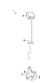
- FIG. 1 is an overall schematic configuration diagram of an excretion detection system 1 according to an embodiment of the present invention.
- 1 is a plan development view of a disposable diaper 10 according to an embodiment of the present invention. It is sectional drawing of the disposable diaper 10 along the F3-F3 line
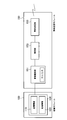
- wire of FIG. 2 is a functional block configuration diagram of an electromotive module 100 and a wireless transmission module 150 according to an embodiment of the present invention.
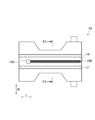
- FIG. FIG. 2 is a perspective view and a cross-sectional view of an electromotive module 100 according to an embodiment of the present invention. It is explanatory drawing about the cause which a difference produces in the ultimate voltage of the electromotive module 100 which concerns on embodiment of this invention.
- FIG. 1 is an overall schematic configuration diagram of an excretion detection system 1 according to this embodiment.
- the excretion detection system 1 includes a disposable diaper 10, a wireless relay station 20, and an excretion detection server 30.
- the disposable diaper 10 is a general open type (tape type).
- the disposable diaper 10 is equipped with an electromotive module 100 that generates electromotive force by urine and a wireless transmission module 150 that transmits a wireless signal to the wireless relay station 20.
- the wireless transmission module 150 transmits a wireless signal according to a predetermined wireless communication method to the wireless relay station 20.
- the wireless transmission module 150 transmits to the wireless relay station 20 a wireless signal indicating that urination has occurred due to the electromotive force obtained by the electromotive module 100 coming into contact with urine.
- the wireless transmission module 150 may include a temperature sensor (not shown) and the like, and transmit a wireless signal multiplexed with output data from the sensor toward the wireless relay station 20.
- the excretion detection server 30 receives a signal indicating that a wireless signal is transmitted from the wireless transmission module 150 via the wireless relay station 20.
- the excretion detection server 30 detects the presence or absence of excretion of the wearer of the disposable diaper 10 based on the signal.
- FIG. 2 is a plan development view of the disposable diaper 10.
- FIG. 3 is a cross-sectional view of the disposable diaper 10 taken along line F3-F3 in FIG.
- the disposable diaper 10 includes a liquid-permeable top sheet 11, a liquid-impermeable back sheet 15, and an absorbent body 14 provided between the top sheet 11 and the back sheet 15.
- the second sheet 12 is provided between the top sheet 11 and the absorbent body 14, and the absorbent body 14 is covered with the water absorbent paper 13.
- a back nonwoven fabric 16 is provided outside the back sheet 15.
- a pair of gathered nonwoven fabrics 17 is provided outside the product width direction W of the absorbent body 14.
- An elastic member 18 is provided at the free end of the gathered nonwoven fabric 17 along the product longitudinal direction L.
- each member which comprises the disposable diaper 10 is not specifically limited, For example, the following members can be used.
- Top sheet 11 Through air nonwoven fabric 25g / m 2 ⁇
- Second sheet 12 Through air nonwoven fabric 25g / m 2 ⁇
- Water absorbent paper 13 Tissue (pulp) 17g / m 2
- Back sheet 15 Polyethylene film 18g / m 2 ⁇
- Back nonwoven fabric 16 Spunbond nonwoven fabric 17g / m 2 ⁇ Gathered nonwoven fabric 17: Spunbond-Melt-Bron-Spunbonded nonwoven fabric 15g / m 2 ⁇
- Elastic member 18 Rubber thread 620DTEX Each member is bonded by a hot melt adhesive (7 g / m 2 ) applied in a spiral shape.
- the second sheet 12, the water absorbent paper 13, the back nonwoven fabric 16, the gathered nonwoven fabric 17, and the elastic member 18 are not necessarily essential.
- the disposable diaper 10 includes an electromotive module 100 and a wireless transmission module 150.
- the electromotive module 100 is disposed between the top sheet 11 and the absorber 14, more specifically, the second sheet 12 and the absorber 14.
- the electromotive module 100 includes a pair of electromotive electrodes, and is disposed along the product longitudinal direction L at the center in the product width direction W.
- the wireless transmission module 150 is electrically connected to the electromotive module 100.
- the wireless transmission module 150 is configured to be externally attached to the electromotive module 100.
- the connection part of the electromotive module 100 with the wireless transmission module 150 has a structure taken out from the back sheet 15 side of the disposable diaper 10, and the wireless transmission module 150 is connected to the connection part.
- FIG. 4 is a functional block configuration diagram of the electromotive module 100 and the wireless transmission module 150.
- 5A and 5B are a perspective view and a cross-sectional view of the electromotive module 100.
- FIG. 4 is a functional block configuration diagram of the electromotive module 100 and the wireless transmission module 150.
- 5A and 5B are a perspective view and a cross-sectional view of the electromotive module 100.
- the electromotive module 100 includes a pair of electromotive electrodes 110, electromotive electrodes 120, and a base material 130.
- the electromotive electrode 110 and the electromotive electrode 120 are electrodes composed of materials having different ionization tendency, and generate electromotive force by contact with the excrement (urine) of the wearer using the principle of the Volta battery. To do.
- the electromotive electrode 110 and the electromotive electrode 120 have a rectangular sheet shape, and are arranged along the product longitudinal direction L.
- the substrate 130 is provided with an electromotive electrode 110 and an electromotive electrode 120.
- the base material 130 supports the electromotive electrode 110 and the electromotive electrode 120 while maintaining a gap between the electromotive electrode 110 and the electromotive electrode 120.
- the electromotive module 100 has an electrode surface 100f and a substrate surface 100r (see FIG. 5B).
- the electrode surface 100f is a surface where the electromotive electrode 110 and the electromotive electrode 120 are exposed.
- the substrate surface 100r is a surface from which the substrate 130 is exposed.
- the electrode surface 100f faces the absorber 14 (specifically, the absorber 14 covered with the water absorbent paper 13). In other words, consideration is given so that the electromotive electrode 110 and the electromotive electrode 120 can stably come into contact with the absorber 14 that has absorbed urine.
- the specifications of the electromotive electrode 110, the electromotive electrode 120, and the base material 130 according to the present embodiment are as follows.
- Electromotive electrode 110 MnO2 + C sheet (4mm wide) ⁇ Base material sheet: PET75 ⁇ m ⁇ MnO2 ⁇ C mix ratio: Manganese powder / carbon ink * ⁇ Upper layer: 33.3 / 66.6% ⁇ Lower layer: 0/100% (2 color printing) * ⁇ Carbon ink composition (60% carbon, 40% resin (polyester) solvent) ⁇ Thickness ⁇ Lower layer: about 12.5 ⁇ m ⁇ Total thickness: approx.
- Electromotive electrode 120 ⁇ AL sheet (4mm width) ⁇ Film thickness: 50 ⁇ m ⁇ Base material 130 ⁇ Polyethylene terephthalate (PET) ⁇ Film thickness: 75 ⁇ m, 200 ⁇ m, 300 ⁇ m or 400 ⁇ m
- the base material 130 is a sheet-like member formed using PET, and in this embodiment, the electromotive electrode 110 and the electromotive electrode 120, and the base material 130 are acrylic adhesives. It is adhered using.
- the electromotive electrode 110 and electromotive electrode 120 may be fixed to the base material 130 by printing or etching instead of adhesion.
- the width of the electromotive electrode 110 and the electromotive electrode 120 depends on the material and thickness, but when placed inside the disposable diaper 10, if the width is too wide, the wearer of the disposable diaper 10 feels uncomfortable. Learn. In addition, since the film-like sheet is disposed on the absorber 14, the absorption of urine into the absorber 14 is blocked, so that urine residue may be generated on the surface of the electromotive module 100. Conversely, if the width of the electromotive electrode 110 and the electromotive electrode 120 is too narrow, the amount of electromotive force is reduced. Therefore, the width of each electrode is preferably 2 mm or more. Specifically, the width of the electromotive module 100 is preferably 5 mm to 25 mm. Further, the interval (W3) between the electromotive electrode 110 and the electromotive electrode 120 is preferably 1 mm or more.
- the difference between the bending rigidity of the electromotive module 100 and the absorber 14 is 0.5 N or more. , 1.0N or less is set. Specifically, considering the physical properties of the material, the bending rigidity of the electromotive module 100 is preferably 0.6N or more and 1.0N or less, and the absorber is considered in consideration of the bending rigidity of the electromotive module 100. The bending stiffness of 14 is adjusted.
- the electromotive module 100 is bonded to the absorber 14 intermittently (for example, at four corners).
- HMA coated in a spiral shape can be used for adhesion between the electromotive module 100 and the absorber 14.
- the wireless transmission module 150 includes a power storage unit 151, a control unit 153, and a wireless transmission unit 155.
- the power storage unit 151 has a capacitor and stores the electromotive force generated by the electromotive module 100.
- the control unit 153 controls the wireless transmission unit 155 using the electromotive force stored in the power storage unit 151. Further, a temperature sensor (not shown) or the like may be connected to the control unit 153.
- the radio transmission unit 155 transmits a radio signal multiplexed with data indicating temperature, etc., to the radio relay station 20 based on the control from the control unit 153.
- Table 1 shows the test results on the electromotive force of the plurality of disposable diapers 10 having different physical properties of the absorber 14 and the electromotive module 100 (base material 130).
- Electrodes having a width of 4 mm were used, and the electrode interval was set to 1 mm (that is, the total width was 9 mm).
- the lengths of the electromotive electrode 110 and the electromotive electrode 120 were set to 280 mm, which is the length of the absorber 14, assuming that the urination position varies depending on the sex and posture.
- the thickness of the PET film sheet of the substrate 130 was changed to 0.075 mm, 0.2 mm, 0.3 mm, and 0.4 mm (75 ⁇ m, 200 ⁇ m, 300 ⁇ m, or 400 ⁇ m).
- the taper stiffness tester Yamada Seiki Seisakusho was used for the measurement of bending rigidity.
- FIG. 6A and 6 (b) are explanatory diagrams illustrating the cause of the difference in the ultimate voltage.
- FIG. 6A shows a cross-sectional shape when the disposable diaper 10 is worn.
- FIG.6 (b) shows the cross-sectional shape at the time of wear of the disposable diaper of a comparative example.
- the power storage unit 151 is efficiently activated. You have to store the electricity. Even when the amount of urine is small or when there is little contact of urine with the electromotive electrode 110 and the electromotive electrode 120, it is necessary to efficiently generate electricity.
- the difference between the bending rigidity of the electromotive module 100 and the bending rigidity of the absorber 14 is set to approximately 0.5 N or more and 1.0 N or less, whereby the electromotive electrode 110 is formed.
- the electromotive electrode 120 firmly follows the deformation of the absorber 14, even when the absorber 14 is deformed by wearing, an electromotive force sufficient to start the wireless transmission module 150 can be continuously generated. That is, since the power necessary for the operation of the control unit 153 and the wireless transmission unit 155 is quickly stored in the power storage unit 151, the transmission delay of the data indicating the temperature is prevented, and it is possible to quickly detect that there is excretion.
- the electromotive force can be generated more efficiently by setting the bending rigidity of the electromotive module 100 to 0.6 N or more and 1.0 N or less and the width to 5 mm or more and 25 mm or less. Furthermore, by using a sheet-like member formed using polyethylene terephthalate as the base material 130, the characteristics of the electromotive module 100 as described above can be easily realized.
- the electromotive module 100 is connected to the wireless transmission module 150, but the wireless transmission module 150 is not necessarily required. Instead of the wireless transmission module 150, it may be connected to a storage device that accumulates temperature sensor data or another measurement system.
Landscapes
- Health & Medical Sciences (AREA)
- Epidemiology (AREA)
- Engineering & Computer Science (AREA)
- Biomedical Technology (AREA)
- Heart & Thoracic Surgery (AREA)
- Vascular Medicine (AREA)
- Life Sciences & Earth Sciences (AREA)
- Animal Behavior & Ethology (AREA)
- General Health & Medical Sciences (AREA)
- Public Health (AREA)
- Veterinary Medicine (AREA)
- Absorbent Articles And Supports Therefor (AREA)
- Orthopedics, Nursing, And Contraception (AREA)
Abstract
起電モジュール(100)は、イオン化傾向の異なる材料を用いて構成され、尿と接触することによって起電力を発生する起電電極(110)及び起電電極(120)と、起電電極が設けられる基材(130)とを備える。起電電極(110)及び起電電極(120)は、起電電極(110)及び起電電極(120)が露出する電極面(100f)を有する。電極面(100f)は、吸収体(14)と面しており、起電モジュール(100)の曲げ剛性と、吸収体(14)の曲げ剛性との差は、0.5N 以上、1.0N 以下である。
Description
本発明は、吸収体を有する使い捨て着用物品に備えられる起電モジュール及び使い捨て着用物品に関する。
従来、使い捨ておむつなど、吸収体を有する使い捨て着用物品において、一対の電極を設け、吸収体に吸収された尿と一対の電極とが接触することによって発生した起電力を利用する技術が知られている(例えば、特許文献1、第8-9頁、第4図)。
具体的には、特許文献1には、発生した起電力をして無線信号を送信する無線送信モジュールなどを起動させ、排泄を検知するサーバにデータ(具体的には温度を示すデータ)を送信することが開示されている。
しかしながら、上述した尿と一対の電極とが接触することによって発生した起電力を利用する技術には、次のような問題があった。すなわち、無線送信モジュールの起動には0.9V/(100μA)程度のエネルギーが必要であるが、尿による起電力は僅かであるために、発生した起電力を昇圧しなければならない。ここで、起電力の昇圧に時間を要すと、データの送信が遅れ、排泄があったことを速やかに検知できない。
特に、使い捨て着用物品の内部に設けられた電極は、着用者に着用されると吸収体とともに変形するが、このような変形によって吸収体と電極との間に隙間が生じる。このため、吸収体(つまり、尿)との接触面積が狭まり、起電力が低下する。
そこで、本発明は、このよう状況に鑑みてなされたものであり、着用によって吸収体が変形した場合でも、無線送信モジュールなどを起動するために十分な起電力を継続的に発生し得る起電モジュール及び使い捨て着用物品の提供を目的とする。
本発明の第1の特徴は、吸収体(吸収体14)を有する使い捨て着用物品(使い捨ておむつ10)に備えられる起電モジュール(起電モジュール100)であって、イオン化傾向の異なる材料を用いて構成され、尿と接触することによって起電力を発生する起電電極(起電電極110, 起電電極120)と、前記起電電極が設けられる基材(基材130)とを備え、前記起電電極は、前記起電電極が露出する電極面(電極面100f)を有し、前記電極面は、前記吸収体と面しており、前記起電モジュールの曲げ剛性と、前記吸収体の曲げ剛性との差は、0.5N以上、1.0N以下であることを要旨とする。
本発明の第2の特徴は、液透過性のトップシート(トップシート11)、液不透過性のバックシート(バックシート15)、及び前記トップシートと前記バックシートとの間に設けられる吸収体(吸収体14)を備える使い捨て着用物品(使い捨ておむつ10)であって、イオン化傾向の異なる材料を用いて構成され、尿と接触することによって起電力を発生する起電電極と、前記起電電極が設けられる基材とを備え、前記起電電極は、前記起電電極が露出する電極面を有し、前記電極面は、前記吸収体と面しており、前記起電モジュールの曲げ剛性と、前記吸収体の曲げ剛性との差は、0.5N以上、1.0N以下であることを要旨とする。
次に、本発明に係る起電モジュールを備えた使い捨て着用物品(使い捨ておむつ)の実施形態について、図面を参照しながら説明する。なお、以下の図面の記載において、同一または類似の部分には、同一または類似の符号を付している。ただし、図面は模式的なものであり、各寸法の比率などは現実のものとは異なることに留意すべきである。
したがって、具体的な寸法などは以下の説明を参酌して判断すべきである。また、図面相互間においても互いの寸法の関係や比率が異なる部分が含まれ得る。
(1)排泄検知システム全体概略構成
図1は、本実施形態に係る排泄検知システム1の全体概略構成図である。図1に示すように、排泄検知システム1は、使い捨ておむつ10、無線中継局20及び排泄検知サーバ30によって構成される。
図1は、本実施形態に係る排泄検知システム1の全体概略構成図である。図1に示すように、排泄検知システム1は、使い捨ておむつ10、無線中継局20及び排泄検知サーバ30によって構成される。
使い捨ておむつ10は、一般的なオープンタイプ(テープ式)である。使い捨ておむつ10には、尿によって起電力を発生する起電モジュール100と、無線中継局20に向けて無線信号を送信する無線送信モジュール150とが搭載されている。
無線送信モジュール150は、所定の無線通信方式に従った無線信号を無線中継局20に向けて送信する。例えば、無線送信モジュール150は、起電モジュール100が尿と接触することで得られる起電力によって排尿があったことを示す無線信号を無線中継局20に向けて送信する。或いは、無線送信モジュール150は、温度センサ(不図示)などを有し、当該センサからの出力データが多重された無線信号を無線中継局20に向けて送信してもよい。
排泄検知サーバ30は、無線送信モジュール150から無線信号が送信されたことを示す信号を、無線中継局20を介して受信する。排泄検知サーバ30は、当該信号に基づいて、使い捨ておむつ10の着用者の排泄の有無を検出する。
(2)使い捨て着用物品の構成
図2は、使い捨ておむつ10の平面展開図である。図3は、図2のF3-F3線に沿った使い捨ておむつ10の断面図である。
図2は、使い捨ておむつ10の平面展開図である。図3は、図2のF3-F3線に沿った使い捨ておむつ10の断面図である。
図2及び図3に示すように、使い捨ておむつ10は、液透過性のトップシート11、液不透過性のバックシート15、及びトップシート11とバックシート15との間に設けられる吸収体14を備える。本実施形態では、トップシート11と吸収体14との間にセカンドシート12が備えられ、吸収体14は、吸水紙13によって覆われている。また、バックシート15の外側には、バック不織布16が備えられる。
さらに、本実施形態では、吸収体14の製品幅方向W外側に一対のギャザー不織布17が備えられる。ギャザー不織布17の自由端部には、製品長手方向Lに沿って弾性部材18が備えられる。
なお、使い捨ておむつ10を構成する各部材は特に限定されないが、例えば、以下のような部材を用いることができる。
・トップシート11: スルーエア不織布 25g/m2
・セカンドシート12: スルーエア不織布 25g/m2
・吸水紙13: ティッシュ(パルプ) 17g/m2
・吸収体14: パルプ及びSAP(重量比率=50:50) 340g/m2
・バックシート15: ポリエチレンフィルム 18g/m2
・バック不織布16: スパンボンド不織布 17g/m2
・ギャザー不織布17: スパンボンド-メルトブロン-スパンボンド不織布 15g/m2
・弾性部材18: 糸ゴム 620DTEX
なお、各部材は、スパイラル状に塗布されたホットメルト接着剤(7g/m2)によって接合されている。また、セカンドシート12、吸水紙13、バック不織布16、ギャザー不織布17及び弾性部材18は、必ずしも必須ではない。
・セカンドシート12: スルーエア不織布 25g/m2
・吸水紙13: ティッシュ(パルプ) 17g/m2
・吸収体14: パルプ及びSAP(重量比率=50:50) 340g/m2
・バックシート15: ポリエチレンフィルム 18g/m2
・バック不織布16: スパンボンド不織布 17g/m2
・ギャザー不織布17: スパンボンド-メルトブロン-スパンボンド不織布 15g/m2
・弾性部材18: 糸ゴム 620DTEX
なお、各部材は、スパイラル状に塗布されたホットメルト接着剤(7g/m2)によって接合されている。また、セカンドシート12、吸水紙13、バック不織布16、ギャザー不織布17及び弾性部材18は、必ずしも必須ではない。
使い捨ておむつ10には、起電モジュール100及び無線送信モジュール150が備えられる。具体的には、起電モジュール100はトップシート11と吸収体14との間、より具体的にはセカンドシート12と吸収体14に配置される。起電モジュール100は、後述するように一対の起電電極を含み、製品幅方向Wの中央部に、製品長手方向Lに沿って配置される。無線送信モジュール150は、起電モジュール100に電気的に接続される。
無線送信モジュール150は、起電モジュール100に対して外付けできるように構成されている。具体的には、起電モジュール100の無線送信モジュール150との接続部は、使い捨ておむつ10のバックシート15側より取り出した構造となっており、当該接続部に無線送信モジュール150が接続される。
(3)起電モジュール及び無線送信モジュールの構成
次に、図4及び図5を参照して、起電モジュール100及び無線送信モジュール150の構成について説明する。図4は、起電モジュール100及び無線送信モジュール150の機能ブロック構成図である。図5(a)及び(b)は、起電モジュール100の斜視図及び断面図である。
次に、図4及び図5を参照して、起電モジュール100及び無線送信モジュール150の構成について説明する。図4は、起電モジュール100及び無線送信モジュール150の機能ブロック構成図である。図5(a)及び(b)は、起電モジュール100の斜視図及び断面図である。
(3.1)起電モジュール
図4及び図5に示すように、起電モジュール100は、一対の起電電極110及び起電電極120と、基材130とによって構成される。
図4及び図5に示すように、起電モジュール100は、一対の起電電極110及び起電電極120と、基材130とによって構成される。
起電電極110及び起電電極120は、イオン化傾向が異なる材料によって構成される電極であり、ボルタの電池の原理を利用し、着用者の排泄物(尿)が接触することによって起電力を発生する。起電電極110及び起電電極120は、長方形状のシート状であり、製品長手方向Lに沿って配置される。
基材130には、起電電極110及び起電電極120が設けられる。基材130は、起電電極110と起電電極120との間隔を保持しつつ、起電電極110と起電電極120を支持する。
起電モジュール100は、電極面100f及び基材面100rを有する(図5(b)参照)。電極面100fは、起電電極110及び起電電極120が露出する面である。基材面100rは、基材130が露出する面である。電極面100fは、吸収体14(具体的には吸水紙13で覆われた吸収体14)と面している。つまり、起電電極110及び起電電極120が尿を吸収した吸収体14と安定して接触できるように配慮されている。
本実施形態に係る起電電極110、起電電極120及び基材130の仕様は、以下のとおりである。
・起電電極110
・MnO2+Cシート(幅4mm)
・基材シート: PET75μm
・MnO2・C配合比率: マンガン粉末/カーボンインク※
・上層: 33.3/66.6%
・下層: 0/100%(2色印刷)
※・カーボンインク組成(カーボン60%、樹脂(ポリエステル系)溶剤40%)
・膜厚
・下層: 約12.5μm
・総厚: 約40μm
・起電電極120
・ALシート(幅4mm)
・膜厚: 50μm
・基材130
・ポリエチレンテレフタラート(PET)
・膜厚: 75μm、200μm、300μmまたは400μm
上述したように、基材130は、PETを用いて形成されたシート状の部材であり、本実施形態では、起電電極110及び起電電極120と、基材130とは、アクリル系接着剤を用いて接着されている。なお、起電電極110及び起電電極120は、接着に代えて印刷またはエッチングによって基材130に固定してもよい。
・MnO2+Cシート(幅4mm)
・基材シート: PET75μm
・MnO2・C配合比率: マンガン粉末/カーボンインク※
・上層: 33.3/66.6%
・下層: 0/100%(2色印刷)
※・カーボンインク組成(カーボン60%、樹脂(ポリエステル系)溶剤40%)
・膜厚
・下層: 約12.5μm
・総厚: 約40μm
・起電電極120
・ALシート(幅4mm)
・膜厚: 50μm
・基材130
・ポリエチレンテレフタラート(PET)
・膜厚: 75μm、200μm、300μmまたは400μm
上述したように、基材130は、PETを用いて形成されたシート状の部材であり、本実施形態では、起電電極110及び起電電極120と、基材130とは、アクリル系接着剤を用いて接着されている。なお、起電電極110及び起電電極120は、接着に代えて印刷またはエッチングによって基材130に固定してもよい。
起電電極110及び起電電極120の幅(W1及びW2)は、その材質及び厚みにもよるが、使い捨ておむつ10内部に配置する場合、幅が広すぎると使い捨ておむつ10の着用者が違和感を覚える。また、膜状のシートを吸収体14上に配置するため、吸収体14への尿の吸収が遮られるため、起電モジュール100の表面に尿残りが発生し得る。逆に、起電電極110及び起電電極120の幅が細すぎると起電量が少なくなるため、各電極の幅は2mm以上とすることが好ましい。具体的には、起電モジュール100の幅は、5mm~25mmとすることが好ましい。また、起電電極110と起電電極120との間隔(W3)は、1mm以上とすることが好ましい。
さらに、使い捨ておむつ10の着用時においても起電モジュール100を吸収体14に安定して接触させるため、起電モジュール100の曲げ剛性と、吸収体14の曲げ剛性との差は、0.5N以上、1.0N以下となるように設定される。具体的には、材料の物性などを考慮すると、起電モジュール100の曲げ剛性は、0.6N以上、1.0N以下であることが好ましく、起電モジュール100の曲げ剛性を考慮して吸収体14の曲げ剛性が調整される。
また、起電モジュール100は、吸収体14に間欠的(例えば、四隅)に接着されることが好ましい。起電モジュール100と吸収体14との接着には、例えば、スパイラル状に塗布されたHMAを用いることができる。
(3.2)無線送信モジュール
図4に示すように、無線送信モジュール150は、蓄電電源部151、制御部153及び無線送信部155を備える。
図4に示すように、無線送信モジュール150は、蓄電電源部151、制御部153及び無線送信部155を備える。
蓄電電源部151は、キャパシタを有し、起電モジュール100によって起電された起電力を蓄える。
制御部153は、蓄電電源部151に蓄えられた起電力を用いて無線送信部155を制御する。また、制御部153には、図示しない温度センサなどが接続されていてもよい。
無線送信部155は、制御部153からの制御に基づいて温度を示すデータなどが多重された無線信号を無線中継局20に向けて送信する。
(4)作用・効果
次に、本実施形態に係る使い捨ておむつ10の作用及び効果について説明する。表1は、吸収体14及び起電モジュール100(基材130)の物性が異なる複数の使い捨ておむつ10による起電力についての試験結果を示す。

次に、本実施形態に係る使い捨ておむつ10の作用及び効果について説明する。表1は、吸収体14及び起電モジュール100(基材130)の物性が異なる複数の使い捨ておむつ10による起電力についての試験結果を示す。
表1に示す試験に用いた起電モジュール100では、4mm幅の電極を用い、電極の間隔を1mm(つまり、総幅は9mm)に設定した。また、起電電極110及び起電電極120の長さは、性別や姿勢により排尿位置が異なることを想定し、吸収体14の長さである280mmに設定した。
試験では、アクリル製の固定用治具に固定された使い捨ておむつ10に80ccの人工尿(塩濃度:0.9%)を注入し、起電モジュール100と人工尿の接触により発生した電圧を測定した。異なる曲げ剛性を得るため、基材130のPETフィルムシートの厚みを、0.075mm、0.2mm、0.3mm、0.4mm(75μm、200μm、300μmまたは400μm)に変化させた。また、曲げ剛性の測定には、テーパースティフネステスター(安田精機製作所)を用いた。
表1に示すように、起電モジュール100の曲げ剛性と、吸収体14の曲げ剛性との差が概ね0.5N以上、1.0N以下であることによって、人工尿の注入から60秒後の到達電圧が無線送信モジュール150の動作に必要な0.9V程度まで上昇している。
図6(a)及び(b)は、このような到達電圧に差が生じる原因についての説明図である。図6(a)は、使い捨ておむつ10の着用時における断面形状を示す。図6(b)は、比較例の使い捨ておむつの着用時における断面形状を示す。
図6(b)に示すように、起電モジュール100のPETフィルム(基材130)が薄い(柔らかい)と吸収体14が変形した場合、起電モジュール100だけが先に曲がってしまい、吸収体14から浮いてきてしまい、隙間Gが生じる。また、起電モジュール100のPETフィルムが厚い(硬い)と起電モジュール100が吸収体14の変形に追従しなくなり、起電電極と吸収体間に隙間Gが生じる。
一方、図6(a)に示すように、起電電極の剛性(柔軟性)を吸収体14の剛性(柔軟性)と同等程度の適正な範囲にすることによって、吸収体14と起電電極110及び起電電極120との接触が安定的になり、効率的に起電力確保できる。
上述したように、尿と起電電極110及び起電電極120が接触することによって得られる起電力は微弱であるため、無線送信モジュール150を起動させるためには、効率よく蓄電電源部151に起電された電気を蓄えなければならない。尿量が少ない場合や、起電電極110及び起電電極120に尿の接触が少ない場合でも効率的に起電する必要がある。
本実施形態に係る使い捨ておむつ10によれば、起電モジュール100の曲げ剛性と、吸収体14の曲げ剛性との差が概ね0.5N以上、1.0N以下とすることによって、起電電極110及び起電電極120が吸収体14の変形にしっかりと追従するため、着用によって吸収体14が変形した場合でも、無線送信モジュール150を起動するために十分な起電力を継続的に発生し得る。つまり、蓄電電源部151に制御部153及び無線送信部155の動作に必要な電力が速やかに蓄えられるため、温度を示すデータの送信遅延が防止され、排泄があったことを速やかに検知できる。
また、起電モジュール100の曲げ剛性を0.6N以上、1.0N以下とし、幅を5mm以上、25mm以下とすることによって、より効率的に起電力を発生させることができる。さらに、基材130として、ポリエチレンテレフタラートを用いて形成されたシート状の部材を用いることによって、上述したような起電モジュール100の特性を容易に実現し得る。
(5)その他の実施形態
上述したように、本発明の実施形態を通じて本発明の内容を開示したが、この開示の一部をなす論述及び図面は、本発明を限定するものであると理解すべきではない。この開示から当業者には様々な代替実施の形態、実施例及び運用技術が明らかとなる。
上述したように、本発明の実施形態を通じて本発明の内容を開示したが、この開示の一部をなす論述及び図面は、本発明を限定するものであると理解すべきではない。この開示から当業者には様々な代替実施の形態、実施例及び運用技術が明らかとなる。
例えば、上述した実施形態では、起電モジュール100は、無線送信モジュール150と接続されていたが、無線送信モジュール150は必ずしも必須ではない。無線送信モジュール150に代えて、温度センサのデータを蓄積する記憶デバイスや、他の計測システムと接続するようにしてもよい。
このように、本発明は、ここでは記載していない様々な実施の形態などを含むことは勿論である。したがって、本発明の技術的範囲は、上述の説明から妥当な特許請求の範囲に係る発明特定事項によってのみ定められるものである。
なお、日本国特許出願第2011-236535号(2011年10月27日出願)の全内容が、参照により、本願明細書に組み込まれている。
着用によって吸収体が変形した場合でも、無線送信モジュールなどを起動するために十分な起電力を継続的に発生し得る起電モジュール及び使い捨て着用物品を提供することができる。
1…排泄検知システム
10…使い捨ておむつ
11…トップシート
12…セカンドシート
13…吸水紙
14…吸収体
15…バックシート
16…バック不織布
17…ギャザー不織布
18…弾性部材
20…無線中継局
30…排泄検知サーバ
100…起電モジュール
100f…電極面
100r…基材面
110, 120…起電電極
130…基材
150…無線送信モジュール
151…蓄電電源部
153…制御部
155…無線送信部
10…使い捨ておむつ
11…トップシート
12…セカンドシート
13…吸水紙
14…吸収体
15…バックシート
16…バック不織布
17…ギャザー不織布
18…弾性部材
20…無線中継局
30…排泄検知サーバ
100…起電モジュール
100f…電極面
100r…基材面
110, 120…起電電極
130…基材
150…無線送信モジュール
151…蓄電電源部
153…制御部
155…無線送信部
Claims (6)
- 吸収体を有する使い捨て着用物品に備えられる起電モジュールであって、
イオン化傾向の異なる材料を用いて構成され、尿と接触することによって起電力を発生する起電電極と、
前記起電電極が設けられる基材と
を備え、
前記起電電極は、前記起電電極が露出する電極面を有し、
前記電極面は、前記吸収体と面しており、
前記起電モジュールの曲げ剛性と、前記吸収体の曲げ剛性との差は、0.5N以上、1.0N以下である起電モジュール。 - 前記起電モジュールの曲げ剛性は、0.6N以上、1.0N以下である請求項1に記載の起電モジュール。
- 前記起電モジュールの幅は、5mm以上、25mm以下である請求項1または2に記載の起電モジュール。
- 前記基材は、ポリエチレンテレフタラートを用いて形成されたシート状の部材である請求項1乃至3の何れか一項に記載の起電モジュール。
- 前記起電モジュールは、前記吸収体に間欠的に接着される請求項1乃至4の何れか一項に記載の起電モジュール。
- 液透過性のトップシート、液不透過性のバックシート、及び前記トップシートと前記バックシートとの間に設けられる吸収体を備える使い捨て着用物品であって、
イオン化傾向の異なる材料を用いて構成され、尿と接触することによって起電力を発生する起電電極と、
前記起電電極が設けられる基材と
を備え、
前記起電電極は、前記起電電極が露出する電極面を有し、
前記電極面は、前記吸収体と面しており、
前記起電モジュールの曲げ剛性と、前記吸収体の曲げ剛性との差は、0.5N以上、1.0N以下である使い捨て着用物品。
Applications Claiming Priority (2)
| Application Number | Priority Date | Filing Date | Title |
|---|---|---|---|
| JP2011-236535 | 2011-10-27 | ||
| JP2011236535A JP5979847B2 (ja) | 2011-10-27 | 2011-10-27 | 起電モジュール及び使い捨て着用物品 |
Publications (1)
| Publication Number | Publication Date |
|---|---|
| WO2013061963A1 true WO2013061963A1 (ja) | 2013-05-02 |
Family
ID=48167793
Family Applications (1)
| Application Number | Title | Priority Date | Filing Date |
|---|---|---|---|
| PCT/JP2012/077359 Ceased WO2013061963A1 (ja) | 2011-10-27 | 2012-10-23 | 起電モジュール及び使い捨て着用物品 |
Country Status (2)
| Country | Link |
|---|---|
| JP (1) | JP5979847B2 (ja) |
| WO (1) | WO2013061963A1 (ja) |
Cited By (8)
| Publication number | Priority date | Publication date | Assignee | Title |
|---|---|---|---|---|
| JP2016114399A (ja) * | 2014-12-12 | 2016-06-23 | 国立大学法人東北大学 | センサチップ、検出システム、及び、検出方法 |
| US9907707B2 (en) | 2011-06-03 | 2018-03-06 | The Procter & Gamble Company | Sensor systems comprising auxiliary articles |
| US10285872B2 (en) | 2016-03-03 | 2019-05-14 | The Procter & Gamble Company | Absorbent article with sensor |
| US10292112B2 (en) | 2013-08-08 | 2019-05-14 | The Procter & Gamble Company | Sensor systems for absorbent articles comprising sensor gates |
| US11013640B2 (en) | 2018-05-04 | 2021-05-25 | The Procter & Gamble Company | Sensor devices and systems for monitoring the basic needs of an infant |
| US11051996B2 (en) | 2018-08-27 | 2021-07-06 | The Procter & Gamble Company | Sensor devices and systems for monitoring the basic needs of an infant |
| US20240003718A1 (en) * | 2022-06-29 | 2024-01-04 | The Ritsumeikan Trust | Power generation sensor |
| US20240004099A1 (en) * | 2022-06-29 | 2024-01-04 | The Ritsumeikan Trust | Power generation sensor |
Families Citing this family (7)
| Publication number | Priority date | Publication date | Assignee | Title |
|---|---|---|---|---|
| JP6327459B2 (ja) * | 2014-06-05 | 2018-05-23 | ユニ・チャーム株式会社 | 起電モジュール、及び、着用物品 |
| JP2016093209A (ja) * | 2014-11-04 | 2016-05-26 | スティヒティング アイメック ネダーランドStichting IMEC Nederland | 失禁を監視するシステム |
| US20160120455A1 (en) | 2014-11-04 | 2016-05-05 | Stichting Imec Nederland | Method for monitoring incontinence |
| US20160120454A1 (en) | 2014-11-04 | 2016-05-05 | Stichting Imec Nederland | System for monitoring incontinence |
| KR102404410B1 (ko) * | 2017-08-29 | 2022-06-03 | 한국전자기술연구원 | 자가발전 소변 센서 장치 및 이를 채용한 기저귀 장치 |
| JP7122738B2 (ja) * | 2018-02-16 | 2022-08-22 | 学校法人立命館 | 吸収部材、吸収部材本体及び電極部材 |
| JP2020006129A (ja) * | 2018-06-27 | 2020-01-16 | 東洋インキScホールディングス株式会社 | 酵素電池が搭載されたおむつ並びにシステム |
Citations (4)
| Publication number | Priority date | Publication date | Assignee | Title |
|---|---|---|---|---|
| JPH05180800A (ja) * | 1992-01-08 | 1993-07-23 | Nippon Denshi Kogyo Kk | 水分検知器及び水分センサー付きオムツ並びにオムツ濡 れ報知装置 |
| US5959535A (en) * | 1995-12-20 | 1999-09-28 | Remsburg; Ralph | Electrogalvanic-powered diaper wetness sensor |
| JP2005052563A (ja) * | 2003-08-07 | 2005-03-03 | Kuraray Medical Inc | 濡れ検出可能なおむつおよびその製造方法 |
| JP2010502253A (ja) * | 2006-08-31 | 2010-01-28 | キンバリー クラーク ワールドワイド インコーポレイテッド | 物品内の可撓性基材を通る導通 |
-
2011
- 2011-10-27 JP JP2011236535A patent/JP5979847B2/ja active Active
-
2012
- 2012-10-23 WO PCT/JP2012/077359 patent/WO2013061963A1/ja not_active Ceased
Patent Citations (4)
| Publication number | Priority date | Publication date | Assignee | Title |
|---|---|---|---|---|
| JPH05180800A (ja) * | 1992-01-08 | 1993-07-23 | Nippon Denshi Kogyo Kk | 水分検知器及び水分センサー付きオムツ並びにオムツ濡 れ報知装置 |
| US5959535A (en) * | 1995-12-20 | 1999-09-28 | Remsburg; Ralph | Electrogalvanic-powered diaper wetness sensor |
| JP2005052563A (ja) * | 2003-08-07 | 2005-03-03 | Kuraray Medical Inc | 濡れ検出可能なおむつおよびその製造方法 |
| JP2010502253A (ja) * | 2006-08-31 | 2010-01-28 | キンバリー クラーク ワールドワイド インコーポレイテッド | 物品内の可撓性基材を通る導通 |
Cited By (23)
| Publication number | Priority date | Publication date | Assignee | Title |
|---|---|---|---|---|
| US11096837B2 (en) | 2011-06-03 | 2021-08-24 | The Procter & Gamble Company | Sensor systems comprising auxiliary articles |
| US9907707B2 (en) | 2011-06-03 | 2018-03-06 | The Procter & Gamble Company | Sensor systems comprising auxiliary articles |
| US10271998B2 (en) | 2011-06-03 | 2019-04-30 | The Procter & Gamble Company | Sensor systems comprising anti-choking features |
| US11633310B2 (en) | 2011-06-03 | 2023-04-25 | The Procter & Gamble Company | Sensor systems comprising auxiliary articles |
| US10864118B2 (en) | 2011-06-03 | 2020-12-15 | The Procter & Gamble Company | Absorbent articles comprising sensors |
| US10869786B2 (en) | 2011-06-03 | 2020-12-22 | The Procter & Gamble Company | Absorbent articles comprising sensors |
| US10932958B2 (en) | 2011-06-03 | 2021-03-02 | The Procter & Gamble Company | Absorbent articles comprising sensors |
| US11452644B2 (en) | 2011-06-03 | 2022-09-27 | The Procter & Gamble Company | Absorbent articles comprising sensors |
| US10292112B2 (en) | 2013-08-08 | 2019-05-14 | The Procter & Gamble Company | Sensor systems for absorbent articles comprising sensor gates |
| US10462750B2 (en) | 2013-08-08 | 2019-10-29 | The Procter & Gamble Company | Sensor systems for absorbent articles comprising sensor gates |
| US10492148B2 (en) | 2013-08-08 | 2019-11-26 | The Procter & Gamble Company | Sensor systems for absorbent articles comprising sensor gates |
| JP2016114399A (ja) * | 2014-12-12 | 2016-06-23 | 国立大学法人東北大学 | センサチップ、検出システム、及び、検出方法 |
| US10285871B2 (en) | 2016-03-03 | 2019-05-14 | The Procter & Gamble Company | Absorbent article with sensor |
| US11464680B2 (en) | 2016-03-03 | 2022-10-11 | The Procter & Gamble Company | Absorbent article with sensor |
| US10285872B2 (en) | 2016-03-03 | 2019-05-14 | The Procter & Gamble Company | Absorbent article with sensor |
| US11051995B2 (en) | 2018-05-04 | 2021-07-06 | The Procter & Gamble Company | Sensor devices and systems for monitoring the basic needs of an infant |
| US11166856B2 (en) | 2018-05-04 | 2021-11-09 | The Procter & Gamble Company | Sensor devices and systems for monitoring the basic needs of an infant |
| US11013640B2 (en) | 2018-05-04 | 2021-05-25 | The Procter & Gamble Company | Sensor devices and systems for monitoring the basic needs of an infant |
| US11051996B2 (en) | 2018-08-27 | 2021-07-06 | The Procter & Gamble Company | Sensor devices and systems for monitoring the basic needs of an infant |
| US20240003718A1 (en) * | 2022-06-29 | 2024-01-04 | The Ritsumeikan Trust | Power generation sensor |
| US20240004099A1 (en) * | 2022-06-29 | 2024-01-04 | The Ritsumeikan Trust | Power generation sensor |
| US12245923B2 (en) * | 2022-06-29 | 2025-03-11 | The Ritsumeikan Trust | Power generation sensor |
| US12411027B2 (en) * | 2022-06-29 | 2025-09-09 | The Ritsumeikan Trust | Power generation sensor |
Also Published As
| Publication number | Publication date |
|---|---|
| JP5979847B2 (ja) | 2016-08-31 |
| JP2013094175A (ja) | 2013-05-20 |
Similar Documents
| Publication | Publication Date | Title |
|---|---|---|
| JP5979847B2 (ja) | 起電モジュール及び使い捨て着用物品 | |
| JP6327459B2 (ja) | 起電モジュール、及び、着用物品 | |
| KR101382728B1 (ko) | 주위 에너지에 의해 전력이 공급되는 모니터링 시스템을 포함하는 흡수용품 | |
| JP3274130B2 (ja) | 尿検知スイッチ、及び、尿検知装置 | |
| KR101593737B1 (ko) | 배설 검출 장치 및 흡수성 물품 | |
| EP3426209B1 (en) | Absorbent article and related methods | |
| US9173799B2 (en) | Urine disposal device | |
| US20040207530A1 (en) | Elimination - absorber monitoring system | |
| CN103429283B (zh) | 漏液传感系统 | |
| JP2015128478A (ja) | 排便排尿判定装置、及び、排便排尿判定方法 | |
| CN211741148U (zh) | 一种排泄物传感器 | |
| CN113081495B (zh) | 一种智能婴儿纸尿裤 | |
| CN219921381U (zh) | 一种便于自供电的智能监测纸尿裤 | |
| JP2012223386A (ja) | 水分センサー | |
| CN103491995A (zh) | 液体检测装置 | |
| JP7122738B2 (ja) | 吸収部材、吸収部材本体及び電極部材 | |
| KR102404410B1 (ko) | 자가발전 소변 센서 장치 및 이를 채용한 기저귀 장치 | |
| CN113081499B (zh) | 一种智能护理成人纸尿裤 | |
| JP3136438B2 (ja) | 濡れ検知センサ及びこれを用いたおむつ濡れ報知装置 | |
| CN204839961U (zh) | 一种尿湿探头及应用该尿湿探头的纸尿裤 | |
| Tanaka et al. | Self-powered wireless urinary-incontinence sensor determines time for diaper change from spacing between sensing signals | |
| CN219941025U (zh) | 一种智能成人纸尿裤 | |
| Douseki et al. | Self-powered wireless disposable sensor for welfare application | |
| JP3841800B2 (ja) | フィルムベースの液漏れセンサー及びその作成方法 | |
| Tanaka et al. | A wireless self-powered urinary incontinence sensor embedded in disposable diapers |
Legal Events
| Date | Code | Title | Description |
|---|---|---|---|
| 121 | Ep: the epo has been informed by wipo that ep was designated in this application |
Ref document number: 12843931 Country of ref document: EP Kind code of ref document: A1 |
|
| NENP | Non-entry into the national phase |
Ref country code: DE |
|
| 122 | Ep: pct application non-entry in european phase |
Ref document number: 12843931 Country of ref document: EP Kind code of ref document: A1 |