WO2013061813A1 - Air roller unit - Google Patents
Air roller unit Download PDFInfo
- Publication number
- WO2013061813A1 WO2013061813A1 PCT/JP2012/076604 JP2012076604W WO2013061813A1 WO 2013061813 A1 WO2013061813 A1 WO 2013061813A1 JP 2012076604 W JP2012076604 W JP 2012076604W WO 2013061813 A1 WO2013061813 A1 WO 2013061813A1
- Authority
- WO
- WIPO (PCT)
- Prior art keywords
- shaft
- air
- collar
- bearing
- roll unit
- Prior art date
Links
Images


Classifications
-
- F—MECHANICAL ENGINEERING; LIGHTING; HEATING; WEAPONS; BLASTING
- F16—ENGINEERING ELEMENTS AND UNITS; GENERAL MEASURES FOR PRODUCING AND MAINTAINING EFFECTIVE FUNCTIONING OF MACHINES OR INSTALLATIONS; THERMAL INSULATION IN GENERAL
- F16C—SHAFTS; FLEXIBLE SHAFTS; ELEMENTS OR CRANKSHAFT MECHANISMS; ROTARY BODIES OTHER THAN GEARING ELEMENTS; BEARINGS
- F16C13/00—Rolls, drums, discs, or the like; Bearings or mountings therefor
- F16C13/02—Bearings
-
- F—MECHANICAL ENGINEERING; LIGHTING; HEATING; WEAPONS; BLASTING
- F16—ENGINEERING ELEMENTS AND UNITS; GENERAL MEASURES FOR PRODUCING AND MAINTAINING EFFECTIVE FUNCTIONING OF MACHINES OR INSTALLATIONS; THERMAL INSULATION IN GENERAL
- F16C—SHAFTS; FLEXIBLE SHAFTS; ELEMENTS OR CRANKSHAFT MECHANISMS; ROTARY BODIES OTHER THAN GEARING ELEMENTS; BEARINGS
- F16C32/00—Bearings not otherwise provided for
- F16C32/06—Bearings not otherwise provided for with moving member supported by a fluid cushion formed, at least to a large extent, otherwise than by movement of the shaft, e.g. hydrostatic air-cushion bearings
- F16C32/0603—Bearings not otherwise provided for with moving member supported by a fluid cushion formed, at least to a large extent, otherwise than by movement of the shaft, e.g. hydrostatic air-cushion bearings supported by a gas cushion, e.g. an air cushion
- F16C32/0614—Bearings not otherwise provided for with moving member supported by a fluid cushion formed, at least to a large extent, otherwise than by movement of the shaft, e.g. hydrostatic air-cushion bearings supported by a gas cushion, e.g. an air cushion the gas being supplied under pressure, e.g. aerostatic bearings
- F16C32/0618—Bearings not otherwise provided for with moving member supported by a fluid cushion formed, at least to a large extent, otherwise than by movement of the shaft, e.g. hydrostatic air-cushion bearings supported by a gas cushion, e.g. an air cushion the gas being supplied under pressure, e.g. aerostatic bearings via porous material
Definitions
- the air roll unit when the air roll unit is in operation, if the air supply to the air bearing is shut off due to a failure or an excessive impact is applied to the roll, the air bearing and the shaft come into contact with each other and the shaft is damaged. Sometimes. Depending on the degree of damage, the shaft must be replaced. In particular, when the roll and the shaft are integrally formed, when replacing the shaft, the roll must also be replaced at the same time, which increases the cost.
- an air roll unit 1 includes a roll 2 having a shaft 21, a cylindrical collar 3 attached to the shaft 21, and an air bearing 4 that supports the collar 3 in a non-contact manner.
- a thrust plate 5 that restricts the movement of the air bearing 4 in the thrust direction
- a detent plate 6 that prevents the collar 3 from rotating relative to the shaft 21, and a housing 7 that holds the air bearing 4. .
- the air bearing 4 is attached to the collar 3 so that the flange 43 and the flange 32 of the collar 3 face each other.
- the collar 3 can be supported in the radial direction without contact (specifically, a compressed air layer L1 for a radial bearing described later between the outer peripheral surface 35 of the collar 3 and the inner peripheral surface 44 of the air bearing 4). 9)
- the inner diameter r5 of the air bearing 4 is set to be larger than the outer diameter r3 of the collar 3 by twice the thickness of the radial air compression compressed air layer L1.
- FIG. 8A is a front view of the housing 7, and FIG. 8B is a cross-sectional view taken along the line FF of FIG. 8A.
Landscapes
- Engineering & Computer Science (AREA)
- General Engineering & Computer Science (AREA)
- Mechanical Engineering (AREA)
- Chemical & Material Sciences (AREA)
- Dispersion Chemistry (AREA)
- Magnetic Bearings And Hydrostatic Bearings (AREA)
- Rolls And Other Rotary Bodies (AREA)
Abstract
Provided is an air roller unit configuration that prevents shaft damage and enables a reduction in costs. The air roller unit (1) is equipped with: a shaft (21) that is connected to a main roller body (20); collars (3) that are attached to the shaft (21); air bearings (4) that support the collars (3) without making contact therewith; and rotation stop plates (6) that are mounted to the collars (3) with a thrust plate (5) interposed therebetween. The inner diameter (r2) of the collars (3) is set to be larger than the outer diameter (r1) of the shaft (21). A slit (67) is formed in each of the rotation stop plates (6) that radially connects the inner peripheral surface (65) and the outer peripheral surface (66) thereof, and a counterbored screw hole (68) is formed from the outer peripheral surface (66) so as to span the slit (67). A bolt (83) is inserted into the counterbored screw hole (68), and the rotation stop plate (6) can be mounted to or dismounted from the shaft (21) by tightening or loosening the bolt (83).
Description
本発明は、ロールを非接触で支持するエアロールユニットの構造に関する。
The present invention relates to a structure of an air roll unit that supports a roll in a non-contact manner.
高い回転精度が求められるテープ、シート、フィルム等の搬送に、ロールを非接触で支持するエアロールユニットが用いられている。エアロールユニットは、ロールと、ロールに連結されたシャフトを非接触で支持するエアベアリングと、を備える。このようなエアロールユニットとして、例えば、特許文献1には、ロールと、ロールと一体的に形成された同芯のシャフトと、シャフトを非接触で支持するエアベアリングと、を備えたエアロールユニットが開示されている。
An air roll unit that supports a roll in a non-contact manner is used for transporting tapes, sheets, films, etc. that require high rotational accuracy. The air roll unit includes a roll and an air bearing that supports a shaft connected to the roll in a non-contact manner. As such an air roll unit, for example, Patent Document 1 discloses an air roll unit that includes a roll, a concentric shaft formed integrally with the roll, and an air bearing that supports the shaft in a non-contact manner. Is disclosed.
ところで、エアロールユニットの作動中に、障害等によりエアベアリングへの給気が遮断されたり、ロールに過大な衝撃が加わったりした場合に、エアベアリングとシャフトとが接触して、シャフトが損傷することがある。損傷の程度によっては、シャフトを交換しなければならい。特に、ロールとシャフトとが一体的に形成されている場合、シャフトを交換する際に、ロールも同時に交換しなければならず、コストが嵩む。
By the way, when the air roll unit is in operation, if the air supply to the air bearing is shut off due to a failure or an excessive impact is applied to the roll, the air bearing and the shaft come into contact with each other and the shaft is damaged. Sometimes. Depending on the degree of damage, the shaft must be replaced. In particular, when the roll and the shaft are integrally formed, when replacing the shaft, the roll must also be replaced at the same time, which increases the cost.
また、エアベアリングでシャフトを非接触で支持するためには、シャフトの外周面とエアベアリングの内周面との間に、圧縮空気層を介在させるための僅かな間隙を形成する必要がある。このため、シャフトの外周面を高精度に加工しなければならない。特に、長いシャフトの外周面を高精度に加工することは困難であり、コストも嵩む。
Also, in order to support the shaft in a non-contact manner with the air bearing, it is necessary to form a slight gap for interposing a compressed air layer between the outer peripheral surface of the shaft and the inner peripheral surface of the air bearing. For this reason, the outer peripheral surface of the shaft must be processed with high accuracy. In particular, it is difficult to process the outer peripheral surface of a long shaft with high accuracy, and the cost increases.
本発明は上記事情に鑑みてなされたものであり、その目的は、シャフトの損傷を防止し、かつコスト低減が可能なエアロールユニットの構造を提供することにある。
The present invention has been made in view of the above circumstances, and an object of the present invention is to provide a structure of an air roll unit capable of preventing damage to the shaft and reducing the cost.
上記課題を解決するために、本発明では、シャフトにカラーを装着し、このカラーを非接触で支持するようにエアベアリングを配置する。また、カラーの、シャフトへの取付けおよびシャフトからの取外しを行う取付手段を設けて、カラーの内径をシャフトの外径より大きくする。
In order to solve the above problems, in the present invention, a collar is mounted on the shaft, and an air bearing is disposed so as to support the collar in a non-contact manner. Also, an attachment means for attaching the collar to the shaft and removing it from the shaft is provided so that the inner diameter of the collar is larger than the outer diameter of the shaft.
例えば、本発明は、ロールを非接触で支持するエアロールユニットであって、
前記ロールに連結されたシャフトと、
前記シャフトの外径よりも大きな内径を有し、当該シャフトが着脱可能に挿入されたカラーと、
前記カラーの外周面を非接触で支持するエアベアリングと、
前記カラーを、前記シャフトから取外し可能に前記シャフトに固定する取付手段と、を有する。 For example, the present invention is an air roll unit that supports a roll in a non-contact manner,
A shaft coupled to the roll;
A collar having an inner diameter larger than the outer diameter of the shaft, and the shaft is detachably inserted;
An air bearing for supporting the outer peripheral surface of the collar in a non-contact manner;
Attachment means for removably fixing the collar to the shaft.
本発明によれば、シャフトに装着されたカラーがエアベアリングにより支持されるので、障害等によりエアベアリングへの給気が遮断されたり、ロールに過大な衝撃が加わったりした場合でも、カラーによりシャフトが保護され、シャフトとエアベアリングとの直接接触を避けることができ、シャフトの損傷を防止することができる。また、カラーは、シャフトに比べて長さを短くすることが可能なため、外周面を高精度に加工することが容易となる。このため、カラーの外周面とエアベアリングの内周面との間に圧縮空気層を介在させるための僅かな間隙を形成するための加工が容易となり、コストを低減できる。また、カラーの、シャフトへの取付およびシャフトからの取外しを行う取付手段を設けるとともに、カラーの内径をシャフトの外径より大きくしているので、カラーの交換作業が容易になるとともに、カラーがシャフトに対して相対的に回転してシャフトの外周面が傷付くのを防止できる。
According to the present invention, since the collar mounted on the shaft is supported by the air bearing, even if the air supply to the air bearing is interrupted due to a failure or an excessive impact is applied to the roll, the collar is used. Is protected, direct contact between the shaft and the air bearing can be avoided, and damage to the shaft can be prevented. Moreover, since the collar can be made shorter than the shaft, it becomes easy to process the outer peripheral surface with high accuracy. For this reason, the process for forming a slight gap for interposing the compressed air layer between the outer peripheral surface of the collar and the inner peripheral surface of the air bearing becomes easy, and the cost can be reduced. In addition, the collar is attached to and removed from the shaft, and the inner diameter of the collar is larger than the outer diameter of the shaft. It is possible to prevent the outer peripheral surface of the shaft from being damaged by rotating relative to the shaft.
以下、本発明の一実施の形態について説明する。
Hereinafter, an embodiment of the present invention will be described.
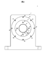
図1は、本実施の形態に係るエアロールユニット1の一部を省略した部分図であり、図2は、図1に示すエアロールユニット1の側面図である。
FIG. 1 is a partial view in which a part of the air roll unit 1 according to the present embodiment is omitted, and FIG. 2 is a side view of the air roll unit 1 shown in FIG.
図示するように、本実施の形態に係るエアロールユニット1は、シャフト21を有するロール2と、シャフト21に装着された円筒形のカラー3と、カラー3を非接触で支持するエアベアリング4と、エアベアリング4のスラスト方向の移動を規制するスラストプレート5と、シャフト21に対するカラー3の相対的な回転を阻止する回り止め板6と、エアベアリング4を保持するハウジング7と、を備えている。
As shown in the figure, an air roll unit 1 according to the present embodiment includes a roll 2 having a shaft 21, a cylindrical collar 3 attached to the shaft 21, and an air bearing 4 that supports the collar 3 in a non-contact manner. A thrust plate 5 that restricts the movement of the air bearing 4 in the thrust direction, a detent plate 6 that prevents the collar 3 from rotating relative to the shaft 21, and a housing 7 that holds the air bearing 4. .
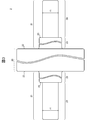
図3は、ロール2の一部を省略した正面図である。
FIG. 3 is a front view in which a part of the roll 2 is omitted.
図示するように、ロール2は、テープ、シート、フィルム等の被搬送物を搬送するためのロール本体20と、ロール本体20の両端面22に一体的に形成されたシャフト21と、を備えている。シャフト21は、ロール本体20と同軸に、ロール本体20の両端面22から突出するように形成されている。シャフト21は、根元部(ロール本体20の端面22との連結部分)23が先端部24よりも大径の段付きシャフトとなっており、このため、シャフト21の根元部23と先端部24との連結部分には段差面25が形成されている。
As shown in the figure, the roll 2 includes a roll body 20 for transporting a transported object such as a tape, a sheet, and a film, and shafts 21 integrally formed on both end faces 22 of the roll body 20. Yes. The shaft 21 is formed so as to protrude from both end faces 22 of the roll body 20 coaxially with the roll body 20. The shaft 21 is a stepped shaft having a root portion (connecting portion with the end surface 22 of the roll body 20) 23 having a diameter larger than that of the tip portion 24. For this reason, the root portion 23 and the tip portion 24 of the shaft 21 A stepped surface 25 is formed at the connecting portion.
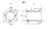
図4(A)は、カラー3の正面図であり、図4(B)は、図4(A)のB-B断面図である。
4A is a front view of the collar 3, and FIG. 4B is a cross-sectional view taken along the line BB of FIG. 4A.
図示するように、カラー3は、円筒状のカラー本体30と、カラー本体30の一方の端面31側の外周から張り出したフランジ32と、を備えている。カラー3の材質は、シャフト21と同材質が望ましい。
As shown in the figure, the collar 3 includes a cylindrical collar body 30 and a flange 32 projecting from the outer periphery of the collar body 30 on the one end face 31 side. The material of the collar 3 is preferably the same material as the shaft 21.
カラー本体30の他方の端面33には、スラストプレート5取付用のネジ穴34が複数形成されている。
A plurality of screw holes 34 for attaching the thrust plate 5 are formed on the other end surface 33 of the collar body 30.
カラー本体30には、フランジ32側の端面31がシャフト21の段差面25と当接するように、フランジ32側からシャフト21が挿入される。また、カラー3をシャフト21から容易に取り外せるように、カラー本体30の内径r2は、シャフト21の外径r1より僅かに大きめ(例えば隙間4μm以下)に設定されている。
The shaft 21 is inserted into the collar body 30 from the flange 32 side so that the end surface 31 on the flange 32 side contacts the stepped surface 25 of the shaft 21. Further, the inner diameter r2 of the collar body 30 is set to be slightly larger than the outer diameter r1 of the shaft 21 (for example, a gap of 4 μm or less) so that the collar 3 can be easily detached from the shaft 21.
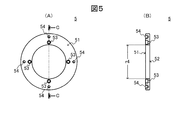
図5(A)は、スラストプレート5の正面図であり、図5(B)は、図5(A)のC-C断面図である。
FIG. 5 (A) is a front view of the thrust plate 5, and FIG. 5 (B) is a sectional view taken along the line CC of FIG. 5 (A).
図示するように、スラストプレート5は、カラー3の内径r2とほぼ同径の内径r4を持つ中空円板状を有しており、一方の面51から他方の面52へ貫通する複数のカラー3取付用のボルト穴53と、一方の面51に開口する複数の回り止め板6取付用のネジ穴54と、が形成されている。
As shown in the figure, the thrust plate 5 has a hollow disk shape having an inner diameter r4 that is substantially the same diameter as the inner diameter r2 of the collar 3, and a plurality of collars 3 penetrating from one surface 51 to the other surface 52. A bolt hole 53 for attachment and a plurality of screw holes 54 for attachment of the rotation stopper plate 6 opened on one surface 51 are formed.
カラー3が装着されたシャフト21をスラストプレート5内に他方の面52側から挿入した状態で、ボルト81を、スラストプレート5のカラー3取付用ボルト穴53のそれぞれに挿入して、カラー3のネジ穴34に螺合させることにより、スラストプレート5は、カラー3の他方の端面33側に取り付けられる。このとき、スラストプレート5の他方の面52は、カラー3のフランジ32の、カラー本体31側の面36に対向する。
With the shaft 21 on which the collar 3 is mounted inserted into the thrust plate 5 from the other surface 52 side, the bolt 81 is inserted into each of the collar 3 mounting bolt holes 53 of the thrust plate 5. The thrust plate 5 is attached to the other end surface 33 side of the collar 3 by being screwed into the screw hole 34. At this time, the other surface 52 of the thrust plate 5 faces the surface 36 on the collar body 31 side of the flange 32 of the collar 3.
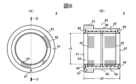
図6(A)は、エアベアリング4の正面図であり、図6(B)は、図6(A)のD-D断面図である。
6A is a front view of the air bearing 4, and FIG. 6B is a DD cross-sectional view of FIG. 6A.
図示するように、エアベアリング4は、円筒状のベアリング本体40と、ベアリング本体40の一方の端面41の外周から張り出したフランジ43と、ベアリング本体40の内周面44側に形成されたラジアル軸受用多孔質焼結層45と、ベアリング本体40の両端面41、42側に形成されたスラスト軸受用多孔質焼結層46と、を備えている。ベアリング本体40の一方の端面41には固定ピン用穴47が形成され、ベアリング本体40の外周面48には止め輪用溝49が形成されている。
As illustrated, the air bearing 4 includes a cylindrical bearing body 40, a flange 43 projecting from the outer periphery of one end surface 41 of the bearing body 40, and a radial bearing formed on the inner peripheral surface 44 side of the bearing body 40. And a porous sintered layer 46 for thrust bearings formed on both end surfaces 41 and 42 side of the bearing body 40. A fixing pin hole 47 is formed on one end surface 41 of the bearing body 40, and a retaining ring groove 49 is formed on the outer peripheral surface 48 of the bearing body 40.
エアベアリング4は、フランジ43とカラー3のフランジ32とが対向するように、カラー3に装着される。また、カラー3を非接触でラジアル方向に支持できるように(具体的には、カラー3の外周面35とエアベアリング4の内周面44との間に後述のラジアル軸受用圧縮空気層L1(図9参照)が形成されるように)、エアベアリング4の内径r5は、ラジアル軸受用圧縮空気層L1の厚さの2倍分、カラー3の外径r3より大きく設定されている。また、スラストプレート5が取り付けられたカラー3を非接触でスラスト方向に支持できるように(具体的には、カラー3のフランジ32の、カラー本体31側の面36と、エアベアリング4の他方の端面42との間、およびエアベアリング4の一方の端面41とスラストプレート5の他方の面52との間に、後述のスラスト軸受用圧縮空気層L2(図9参照)が形成されるように)、エアベアリング4の一方の端面41から他方の端面42までの長さd2は、カラー3の他方の端面33からフランジ32の、カラー本体31側の面36までの長さd1より、両側のスラスト軸受用圧縮空気層L2の厚さ分、短く設定されている。
The air bearing 4 is attached to the collar 3 so that the flange 43 and the flange 32 of the collar 3 face each other. In addition, the collar 3 can be supported in the radial direction without contact (specifically, a compressed air layer L1 for a radial bearing described later between the outer peripheral surface 35 of the collar 3 and the inner peripheral surface 44 of the air bearing 4). 9)), the inner diameter r5 of the air bearing 4 is set to be larger than the outer diameter r3 of the collar 3 by twice the thickness of the radial air compression compressed air layer L1. Further, the collar 3 to which the thrust plate 5 is attached can be supported in the thrust direction in a non-contact manner (specifically, the flange 36 of the collar 3 has a surface 36 on the collar body 31 side and the other side of the air bearing 4). A thrust bearing compressed air layer L2 (see FIG. 9) described later is formed between the end face 42 and between one end face 41 of the air bearing 4 and the other face 52 of the thrust plate 5). The length d2 from one end surface 41 of the air bearing 4 to the other end surface 42 is longer than the length d1 from the other end surface 33 of the collar 3 to the surface 36 of the flange 32 on the collar body 31 side. The thickness is set shorter by the thickness of the bearing compressed air layer L2.
ラジアル軸受用多孔質焼結層45は、ベアリング本体40の内周面44に形成された通気路410(図9参照)に繋がっており、この通気路410を介してポンプ(不図示)より供給された圧縮空気が、ラジアル軸受用多孔質焼結層45内の孔を介して、ラジアル軸受用多孔質焼結層45の表面(ベアリング本体40の内周面44)から均一に放出される。同様に、スラスト軸受用多孔質焼結層46は、ベアリング本体40の両端面41、42に形成された通気路411(図9参照)に繋がっており、これらの通気路411を介してポンプ(不図示)より供給された圧縮空気が、各スラスト軸受用多孔質焼結層46内の孔を介して、各スラスト軸受用多孔質焼結層46の表面(エアベアリング4の両端面41、42)から均一に放出される。固定ピン用穴47は、エアベアリング4に圧縮空気が供給されていない状況におけるエアロールユニット1の運搬、搬入時などにおいて、シャフト21の空回りによるエアベアリング4の内周面44とカラー3の外周面35との摺接防止用の固定ピン(不図示)を挿入するために形成されたピン穴である。止め輪用溝49は、ハウジング7に保持されたエアベアリング4の抜け止め用の止め輪85を装着するために形成された溝である。
The porous sintered layer 45 for radial bearings is connected to an air passage 410 (see FIG. 9) formed on the inner peripheral surface 44 of the bearing body 40, and is supplied from a pump (not shown) through the air passage 410. The compressed air thus formed is uniformly discharged from the surface of the radial sintered porous layer 45 (the inner peripheral surface 44 of the bearing body 40) through the holes in the radial sintered porous layer 45. Similarly, the porous sintered layer 46 for thrust bearings is connected to air passages 411 (see FIG. 9) formed in both end faces 41 and 42 of the bearing body 40, and the pump ( Compressed air supplied from an unillustrated surface passes through the holes in each thrust bearing porous sintered layer 46 and the surfaces of the thrust bearing porous sintered layers 46 (both end faces 41, 42 of the air bearing 4). ) Uniformly. The fixing pin hole 47 is provided on the inner peripheral surface 44 of the air bearing 4 and the outer periphery of the collar 3 due to the idle rotation of the shaft 21 when the air roll unit 1 is transported or carried in a state where compressed air is not supplied to the air bearing 4. It is a pin hole formed for inserting a fixing pin (not shown) for preventing sliding contact with the surface 35. The retaining ring groove 49 is a groove formed for mounting a retaining ring 85 for retaining the air bearing 4 held in the housing 7.
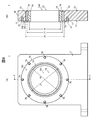
図7(A)は、回り止め板6の正面図であり、図7(B)は、図7(A)のE-E断面図である。
7A is a front view of the rotation stopper plate 6, and FIG. 7B is a cross-sectional view taken along line EE of FIG. 7A.
図示するように、回り止め板6は、中空円板状を有しており、一方の面61から他方の面62へ貫通した複数のスラストプレート5取付用のボルト穴63と、一方の面61から他方の面62へ貫通した固定ピン用穴64と、回り止め板6の内周面65と外周面66とを径方向に繋ぐスリット67と、外周面66からスリット67を跨ぐシャフト21把持用の深座ぐり付きネジ穴68と、が形成されている。
As shown in the figure, the detent plate 6 has a hollow disk shape, a plurality of bolt holes 63 for attaching the thrust plate 5 penetrating from one surface 61 to the other surface 62, and one surface 61. Pin 64 that penetrates from the outer surface 66 to the other surface 62, a slit 67 that connects the inner peripheral surface 65 and the outer peripheral surface 66 of the anti-rotation plate 6 in the radial direction, and for gripping the shaft 21 that spans the slit 67 from the outer peripheral surface 66. And a counterbored screw hole 68 are formed.
回り止め板6の他方の面62がスラストプレート5の一方の面51と当接するように、シャフト21を回り止め板6内に他方の面62側から挿入した状態で、ボルト82を回り止め板6のボルト穴63のそれぞれに挿入して、スラストプレート5のネジ穴54に螺合させることにより、回り止め板6とカラー3とが固定される。また、シャフト21の空回り防止用の固定ピン(不図示)を固定ピン用穴64に挿入して、その先端をエアベアリング4の固定用ピン穴47に差し込むことにより、回り止め板6を介して、シャフト21に対するエアベアリング4の相対的な回転ならびに軸方向の移動が阻止される。
In the state where the shaft 21 is inserted into the anti-rotation plate 6 from the other surface 62 side so that the other surface 62 of the anti-rotation plate 6 comes into contact with the one surface 51 of the thrust plate 5, the bolt 82 is attached to the anti-rotation plate. 6 is inserted into each of the bolt holes 63 and screwed into the screw holes 54 of the thrust plate 5, whereby the detent plate 6 and the collar 3 are fixed. Further, a fixing pin (not shown) for preventing idling of the shaft 21 is inserted into the fixing pin hole 64 and the tip thereof is inserted into the fixing pin hole 47 of the air bearing 4, so that the rotation stop plate 6 is interposed. The relative rotation and axial movement of the air bearing 4 with respect to the shaft 21 are prevented.
ボルト83を深座ぐり付きネジ穴68に挿入して締め込むことにより(図2参照)、スリット67の隙間t1が狭くなり、回り止め板6の内径r6が小さくなる。これにより、回り止め板6が、シャフト21を強固に把持し、シャフト21に固定される。したがって、ボルト83を深座ぐり付きネジ穴68に挿入して締め込んでいない状態では、回り止め板6の内径r6は、回り止め板6をシャフト21から容易に取り外せるように、シャフト21の外径r1より大きくなり、ボルト83を深座ぐり付きネジ穴68に挿入して締め込んだ状態では、回り止め板6の内径r6は、回り止め板6がシャフト21を強固に把持するように、シャフト21の外径r1より小さくなる。
When the bolt 83 is inserted into the deep countersunk screw hole 68 and tightened (see FIG. 2), the gap t1 of the slit 67 is narrowed, and the inner diameter r6 of the rotation stopper plate 6 is reduced. Thereby, the rotation stop plate 6 firmly holds the shaft 21 and is fixed to the shaft 21. Therefore, in the state where the bolt 83 is not inserted into the deep countersunk screw hole 68 and tightened, the inner diameter r6 of the rotation stopper plate 6 is such that the rotation stopper plate 6 can be easily removed from the shaft 21. In a state where the diameter is larger than the diameter r1 and the bolt 83 is inserted into the deep counterbore screw hole 68 and tightened, the inner diameter r6 of the rotation prevention plate 6 is set so that the rotation prevention plate 6 firmly holds the shaft 21. It becomes smaller than the outer diameter r1 of the shaft 21.
図8(A)は、ハウジング7の正面図であり、図8(B)は、図8(A)のF-F断面図である。
8A is a front view of the housing 7, and FIG. 8B is a cross-sectional view taken along the line FF of FIG. 8A.
図示するように、ハウジング7は、エアベアリング4を保持するハウジング本体70と、エアベアリング4嵌入用の中空部740が形成された球面ブッシュ74と、球面ブッシュ74を保持するホルダ75と、中空円板状のストッパ76と、を備えている。
As shown in the drawing, the housing 7 includes a housing main body 70 that holds the air bearing 4, a spherical bush 74 in which a hollow portion 740 for fitting the air bearing 4 is formed, a holder 75 that holds the spherical bush 74, and a hollow circle. And a plate-like stopper 76.
ハウジング本体70には、一方の面71から他方の面72に貫通したエアベアリング4保持用の貫通穴73と、一方の面71側に開口するストッパ76取付用のネジ穴77と、が形成されている。ハウジング本体70の貫通穴73は、ホルダ75抜け止め用の段差79を有する段付き穴となっており、エアベアリング4が中空部740内に嵌入された球面ブッシュ74を保持するホルダ75が、ハウジング本体70の一方の面71から貫通穴73に挿入された場合に、ホルダ75は、この段差79と当接して、ハウジング本体70の他方の面72側から抜け出る方向への移動が阻止される。
The housing body 70 is formed with a through hole 73 for holding the air bearing 4 penetrating from the one surface 71 to the other surface 72 and a screw hole 77 for attaching the stopper 76 opened to the one surface 71 side. ing. The through hole 73 of the housing body 70 is a stepped hole having a step 79 for preventing the holder 75 from coming off, and the holder 75 for holding the spherical bush 74 in which the air bearing 4 is fitted in the hollow portion 740 is provided in the housing. When the holder 75 is inserted into the through hole 73 from the one surface 71 of the main body 70, the holder 75 comes into contact with the step 79 and is prevented from moving in the direction of coming out from the other surface 72 side of the housing main body 70.
ストッパ76には、一方の面761から他方の面762へ貫通した複数のハウジング本体70取付用のボルト穴78が形成されている。また、ストッパ76の内径r7は、球面ブッシュ75の端部の外径r8より大きく、かつ、ハウジング本体70の一方の端面71側における貫通穴73の外径r9より小さく設定されている。エアベアリング4が中空部740内に嵌入された球面ブッシュ74を保持したホルダ75が、ハウジング本体70の貫通穴73の段差79に当接した状態で、ボルト84を、ストッパ76のボルト穴78のそれぞれに挿入し、ハウジング本体70のネジ穴77に螺合させることにより、ストッパ76をハウジング本体70の一方の面71側に取り付けると、ストッパ76により、ハウジング本体70の一方の面71から抜け出る方向へのホルダ75の移動が阻止される。これにより、エアベアリング4がハウジング7に保持される。この状態で、エアベアリング4の止め輪用溝49に止め輪85を装着することにより、ハウジング7に保持されたエアベアリング4のスラスト方向の移動が防止される。
The stopper 76 is formed with a plurality of bolt holes 78 for mounting the housing body 70 penetrating from one surface 761 to the other surface 762. Further, the inner diameter r <b> 7 of the stopper 76 is set to be larger than the outer diameter r <b> 8 of the end portion of the spherical bush 75 and smaller than the outer diameter r <b> 9 of the through hole 73 on the one end face 71 side of the housing body 70. With the holder 75 holding the spherical bush 74 fitted with the air bearing 4 in the hollow portion 740 in contact with the step 79 of the through hole 73 of the housing body 70, the bolt 84 is connected to the bolt hole 78 of the stopper 76. When the stopper 76 is attached to the one surface 71 side of the housing main body 70 by being inserted into each of them and screwed into the screw hole 77 of the housing main body 70, the stopper 76 will pull out from the one surface 71 of the housing main body 70. The movement of the holder 75 to is prevented. Thereby, the air bearing 4 is held by the housing 7. In this state, by attaching the retaining ring 85 to the retaining ring groove 49 of the air bearing 4, the movement of the air bearing 4 held in the housing 7 in the thrust direction is prevented.
つぎに、上記構成のエアロールユニット1において、エアベアリング4への給気中におけるシャフト21の支持状態を説明する。
Next, the support state of the shaft 21 during the air supply to the air bearing 4 in the air roll unit 1 having the above configuration will be described.
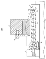
図9は、図1のA部拡大図であり、エアベアリング4への給気中におけるロール2の支持状態を模式的に示した図である。
FIG. 9 is an enlarged view of a part A in FIG. 1, and is a diagram schematically showing a support state of the roll 2 during supply of air to the air bearing 4.
図示するように、組み付け状態(図1の状態)にあるエアロールユニット1において、ポンプ(不図示)から、エアベアリング4内に形成された通気路410に圧縮空気が供給されると、ラジアル軸受用多孔質焼結層45の表面(エアベアリング4の内周面44)から圧縮空気c1が均一に放出され、これにより、カラー3の外周面35とエアベアリング4の内周面44との隙間t2にラジアル軸受用圧縮空気層L1が形成される。このラジアル軸受用圧縮空気層L1により、シャフト21に装着されたカラー3がラジアル方向に非接触で支持される。同様に、エアベアリング4内に形成された通気路411に圧縮空気が供給されると、スラスト軸受用多孔質焼結層46の表面(エアベアリング4の両端面41、42)から圧縮空気c2が均一に放出され、これにより、カラー3のフランジ32の、カラー本体30側の面36とエアベアリング4の他方の端面42との隙間t3、およびエアベアリング4の一方の端面41とスラストプレート5の他方の面52との隙間t4にそれぞれスラスト軸受用圧縮空気層L2が形成される。これらのスラスト軸受用圧縮空気層L2により、シャフト21に装着されたカラー3がスラスト方向に非接触で支持される。
As shown in the drawing, in the air roll unit 1 in the assembled state (state shown in FIG. 1), when compressed air is supplied from a pump (not shown) to the air passage 410 formed in the air bearing 4, a radial bearing is obtained. Compressed air c1 is uniformly discharged from the surface of the porous sintered layer 45 for use (the inner peripheral surface 44 of the air bearing 4), whereby the gap between the outer peripheral surface 35 of the collar 3 and the inner peripheral surface 44 of the air bearing 4 is released. A radial bearing compressed air layer L1 is formed at t2. The collar 3 attached to the shaft 21 is supported in a radial direction in a non-contact manner by the radial bearing compressed air layer L1. Similarly, when compressed air is supplied to the air passage 411 formed in the air bearing 4, the compressed air c <b> 2 is generated from the surface of the thrust bearing porous sintered layer 46 (both end surfaces 41 and 42 of the air bearing 4). As a result, the gap 32 between the surface 36 of the collar body 30 on the collar body 30 side and the other end surface 42 of the air bearing 4 and the one end surface 41 of the air bearing 4 and the thrust plate 5 are released. A thrust bearing compressed air layer L <b> 2 is formed in each gap t <b> 4 with the other surface 52. The collar 3 mounted on the shaft 21 is supported in the thrust direction in a non-contact manner by the thrust bearing compressed air layer L2.
なお、エアロールユニット1において、軸方向の移動を前述のようにスラスト軸受を用いて管理するのではなく、他の手法により管理する場合においては、スラスト軸受ならびにスラストプレート5を省くことも可能である。また、この場合、カラー3のフランジ32を取り除くことも可能である。
In the air roll unit 1, when the axial movement is not managed using the thrust bearing as described above, the thrust bearing and the thrust plate 5 can be omitted when managing by other methods. is there. In this case, the flange 32 of the collar 3 can be removed.
以上、本発明の一実施の形態について説明した。
The embodiment of the present invention has been described above.
本実施の形態に係るエアロールユニット1では、シャフト21の外周にカラー3を装着し、このカラー3を非接触で支持するようにエアベアリング4を配置している。また、回り止め板6を用いて、スラストプレート5が取り付けられたカラー3の、シャフト21への取付およびシャフト21からの取外しを可能にするとともに、カラー3の内径r2をシャフト21の外径r1より大きくしている。
In the air roll unit 1 according to the present embodiment, the collar 3 is mounted on the outer periphery of the shaft 21, and the air bearing 4 is disposed so as to support the collar 3 in a non-contact manner. Further, the collar 3 to which the thrust plate 5 is attached can be attached to the shaft 21 and removed from the shaft 21 by using the anti-rotation plate 6, and the inner diameter r2 of the collar 3 is changed to the outer diameter r1 of the shaft 21. It is bigger.
このように、シャフト21の外周に装着されたカラー3がエアベアリング4により支持されるので、障害等によりエアベアリング4への給気が遮断されたり、ロール2に過大な衝撃が加わったりした場合でも、カラー3がシャフト21を保護し、シャフト21が損傷するのを防止できる。
As described above, since the collar 3 mounted on the outer periphery of the shaft 21 is supported by the air bearing 4, the supply of air to the air bearing 4 is interrupted or an excessive impact is applied to the roll 2 due to a failure or the like. However, the collar 3 protects the shaft 21 and can prevent the shaft 21 from being damaged.
また、カラー3は、シャフト21に比べ長さが短くでき、このため、シャフト21と比べて簡単に、外周面35を高精度に加工できるので、カラー3の外周面35とエアベアリング4の内周面44との間にラジアル軸受用圧縮空気層L1のための僅かな隙間t2を形成するのが容易となり、コストを低減できる。
Further, the collar 3 can be made shorter than the shaft 21, and therefore, the outer peripheral surface 35 can be easily processed with high precision compared to the shaft 21. It is easy to form a slight gap t2 for the radial air compressed air layer L1 between the peripheral surface 44 and the cost can be reduced.
また、回り止め板6を用いることにより、スラストプレート5が取り付けられたカラー3の、シャフト21への取付およびシャフト21からの取外しを可能にするとともに、カラー3の内径r2をシャフト21の外径r1より大きくしているので、カラー3の交換作業が容易になるとともに、カラー3とシャフト21との相対的な回転が阻止されるので、摺接等によりシャフト21の外周面が傷付くのを防止できる。
Further, by using the rotation stopper plate 6, the collar 3 to which the thrust plate 5 is attached can be attached to the shaft 21 and removed from the shaft 21, and the inner diameter r2 of the collar 3 can be set to the outer diameter of the shaft 21. Since it is larger than r1, the replacement operation of the collar 3 is facilitated, and the relative rotation between the collar 3 and the shaft 21 is prevented, so that the outer peripheral surface of the shaft 21 is damaged by sliding contact or the like. Can be prevented.
また、本実施の形態に係るエアロールユニット1では、中空円板状の回り止め板6に、内周面65と外周面66とを繋ぐようにスリット67を形成するとともに、外周面66からスリット67を跨ぐようにシャフト21把持用の深座ぐり付きネジ穴68を形成している。この深座ぐり付きネジ穴68にボルト83を挿入して、このボルト83を締めたり緩めたりすることにより、回り止め板6の内径r6を変化させ、シャフト21への取付および取外しを可能にしている。このため、カラー3の、シャフト21への取付およびシャフト21からの取外しが容易となり、カラー3を交換する際の作業性が向上する。
Further, in the air roll unit 1 according to the present embodiment, the slit 67 is formed in the hollow disc-shaped detent plate 6 so as to connect the inner peripheral surface 65 and the outer peripheral surface 66, and the slit is formed from the outer peripheral surface 66. A deep counterbore screw hole 68 for gripping the shaft 21 is formed so as to straddle 67. By inserting a bolt 83 into the deep counterbore screw hole 68 and tightening or loosening the bolt 83, the inner diameter r6 of the rotation stop plate 6 is changed to enable attachment to and removal from the shaft 21. Yes. For this reason, it becomes easy to attach the collar 3 to the shaft 21 and remove it from the shaft 21, and workability when replacing the collar 3 is improved.
また、本実施の形態に係るエアロールユニット1では、カラー3にスラストプレート5をボルト81で固定し、さらに、このスラストプレート5に回り止め板6をボルト82で固定することにより、カラー3を回り止め板6に固定している。このため、カラー3の、回り止め板6への取付・回り止め板6からの取外しが容易となり、カラー3を交換する際の作業性がさらに向上する。
Further, in the air roll unit 1 according to the present embodiment, the thrust plate 5 is fixed to the collar 3 with the bolts 81, and the rotation stop plate 6 is fixed to the thrust plate 5 with the bolts 82, thereby fixing the collar 3. The rotation stopper plate 6 is fixed. For this reason, it becomes easy to attach the collar 3 to the rotation stopper plate 6 and remove it from the rotation stopper plate 6, and the workability when the collar 3 is replaced is further improved.
また、本実施の形態に係るエアロールユニット1では、ベアリング本体40の一方の端面41に固定ピン用穴47を形成するとともに、回り止め板6に、一方の面61から他方の面62へ貫通する固定ピン用穴64を形成している。このため、固定ピン(不図示)を回り止め板6の固定ピン用穴64に挿入して、その先端をベアリング本体40の固定用ピン穴47に差し込むことにより、回り止め板6を介して、シャフト21に対するエアベアリング4の回転運動を拘束することができる。これにより、エアロールユニット1の運搬、搬入時などにおいて、シャフト21が空回りするのを防止できる。
Further, in the air roll unit 1 according to the present embodiment, the fixing pin hole 47 is formed in the one end surface 41 of the bearing body 40, and the rotation stopper plate 6 is penetrated from the one surface 61 to the other surface 62. A fixing pin hole 64 is formed. For this reason, a fixing pin (not shown) is inserted into the fixing pin hole 64 of the rotation stopper plate 6 and the tip thereof is inserted into the fixing pin hole 47 of the bearing body 40, whereby the rotation stopper plate 6 is interposed. The rotational motion of the air bearing 4 with respect to the shaft 21 can be restricted. Thereby, it is possible to prevent the shaft 21 from idling when the air roll unit 1 is transported or carried in.
また、例えば、様々な内外径寸法のカラー3を準備しておき、作業者が、それらのカラー3のなかから、シャフト21の外径r1とエアベアリング4のベアリング本体40の内径r5に適合するカラー3を選択できるようにすれば、シャフト21とエアベアリング4との組み合わせを選ばない汎用性を実現することができる。
Further, for example, collars 3 having various inner and outer diameter dimensions are prepared, and an operator fits the outer diameter r1 of the shaft 21 and the inner diameter r5 of the bearing body 40 of the air bearing 4 from among the collars 3. If the collar 3 can be selected, versatility can be realized regardless of the combination of the shaft 21 and the air bearing 4.
なお、本発明は上記の実施の形態に限定されるものではなく、その要旨の範囲内で数々の変形が可能である。
Note that the present invention is not limited to the above-described embodiment, and various modifications are possible within the scope of the gist.
例えば、上記の実施の形態では、エアベアリング4として、ベアリング本体40の内周面44側にラジアル軸受用多孔質焼結層45が形成され、ベアリング本体40の両端面41、42側にスラスト軸受用多孔質焼結層46が形成されているものについて説明したが、本発明はこれに限定されない。
For example, in the above embodiment, as the air bearing 4, the radial sintered porous sintered layer 45 is formed on the inner peripheral surface 44 side of the bearing body 40, and the thrust bearing is formed on both end surfaces 41, 42 side of the bearing body 40. Although the description has been given of the case where the porous sintered layer 46 is formed, the present invention is not limited to this.
エアベアリング4は、スラスト軸受用多孔質焼結層46が省略されたものでもよい。この場合でも、ラジアル軸受用多孔質焼結層45から放出された圧縮空気c1が、カラー3のフランジ32の、カラー本体30側の面36とエアベアリング4の他方の端面42との隙間t3、およびエアベアリング4の一方の端面41とスラストプレート5の他方の面52との隙間t4に移動して、スラスト軸受用圧縮空気層L2を形成することが可能である。
The air bearing 4 may be one in which the porous sintered layer 46 for thrust bearing is omitted. Even in this case, the compressed air c1 released from the porous sintered layer 45 for the radial bearing is a gap t3 between the surface 36 of the flange 32 of the collar 3 on the collar body 30 side and the other end surface 42 of the air bearing 4. The thrust bearing compressed air layer L2 can be formed by moving to the gap t4 between one end surface 41 of the air bearing 4 and the other surface 52 of the thrust plate 5.
また、ラジアル軸受用多孔質焼結層45およびスラスト軸受用多孔質焼結層46の代わりに、ベアリング本体40の内周面44、あるいは内周面44および両端面41、42に、エアベアリング4内の通気路410、411に繋がる自成絞りあるいはオリフィス絞りが形成されているものを用いてもよい。
Further, instead of the radial sintered porous bearing layer 45 and the thrust bearing porous sintered layer 46, the air bearing 4 is provided on the inner peripheral surface 44 of the bearing body 40 or the inner peripheral surface 44 and both end surfaces 41, 42. You may use the self-squeezing throttling or orifice throttling connected with the ventilation path 410,411 inside.
本発明は、例えば、ロールが備えるシャフトの損傷を防止し、かつコスト低減が可能なエアロールユニットとしての用途にも適用可能である。
The present invention can be applied to, for example, an application as an air roll unit that prevents damage to a shaft included in a roll and can reduce costs.
1:エアロールユニット、2:ロール、3:カラー、4:エアベアリング、5:スラストプレート、6:回り止め板、7:ハウジング、20:ロール本体、21:シャフト、22:ロール本体20の端面、23:シャフト21の根元部、24:シャフト21の先端部、25:シャフト21の段差面、30:カラー本体、31:カラー本体30の一方の端面、32:フランジ、33:カラー本体30の他方の端面、34:ネジ穴、40:ベアリング本体、41:ベアリング本体40の一方の端面、42:ベアリング本体40の他方の端面、43:フランジ、44:ベアリング本体40の内周面、45:ラジアル軸受用多孔質焼結層、46:スラスト軸受用多孔質焼結層、47:固定ピン用穴、48:ベアリング本体40の外周面、49:止め輪用溝、51:スラストプレート5の一方の面、52:スラストプレート5の他方の面、53:カラー取付用のボルト穴、54:回り止め板取付用のネジ穴、61:回り止め板6の一方の面、62:回り止め板6の他方の面、63:ボルト穴、64:固定ピン用穴、65:回り止め板6の内周面、66:回り止め板6の外周面、67:スリット、68:深座ぐり付きネジ穴、70:ハウジング本体、71:ハウジング本体70の一方の面、72:ハウジング本体70の他方の面、73:貫通穴、74:球面ブッシュ、75:ホルダ、76:ストッパ、77:ネジ穴、78:ボルト穴、79:貫通穴73の段差、81~84:ボルト、85:止め輪、410、411:通気路、740:中空部
1: air roll unit, 2: roll, 3: collar, 4: air bearing, 5: thrust plate, 6: detent plate, 7: housing, 20: roll body, 21: shaft, 22: end face of roll body 20 , 23: root portion of the shaft 21, 24: tip portion of the shaft 21, 25: stepped surface of the shaft 21, 30: collar body, 31: one end surface of the collar body 30, 32: flange, 33: collar body 30 The other end face, 34: screw hole, 40: bearing body, 41: one end face of the bearing body 40, 42: the other end face of the bearing body 40, 43: flange, 44: the inner peripheral face of the bearing body 40, 45: Porous sintered layer for radial bearing, 46: porous sintered layer for thrust bearing, 47: hole for fixing pin, 48: outer peripheral surface of bearing body 40, 49: retaining ring Groove, 51: One surface of thrust plate 5, 52: Other surface of thrust plate 5, 53: Bolt hole for attaching collar, 54: Screw hole for attaching rotation stopper plate, 61: One of rotation stopper plate 6 62: the other surface of the detent plate 6, 63: bolt hole, 64: fixing pin hole, 65: inner peripheral surface of the detent plate 6, 66: outer peripheral surface of the detent plate 6, 67: slit 68: Screw hole with counterbore, 70: Housing body, 71: One surface of the housing body 70, 72: The other surface of the housing body 70, 73: Through hole, 74: Spherical bush, 75: Holder, 76 : Stopper, 77: Screw hole, 78: Bolt hole, 79: Step between the through hole 73, 81 to 84: Bolt, 85: Retaining ring, 410, 411: Ventilation path, 740: Hollow part
Claims (5)
- ロールを非接触で支持するエアロールユニットであって、
前記ロールに連結されたシャフトと、
前記シャフトの外径よりも大きな内径を有し、当該シャフトが着脱可能に挿入されたカラーと、
前記カラーの外周面を非接触で支持するエアベアリングと、
前記カラーを、前記シャフトから取外し可能に前記シャフトに固定する取付手段と、を有する
ことを特徴とするエアロールユニット。 An air roll unit that supports a roll in a non-contact manner,
A shaft coupled to the roll;
A collar having an inner diameter larger than the outer diameter of the shaft, and the shaft is detachably inserted;
An air bearing for supporting the outer peripheral surface of the collar in a non-contact manner;
An air roll unit comprising: an attaching means for fixing the collar to the shaft so as to be removable from the shaft. - 請求項1に記載のエアロールユニットであって、
前記取付手段は、
前記シャフトが挿入された中空円板状の回り止め板と、
前記回り止め板に前記カラーを着脱可能に固定する固定手段と、を有する
ことを特徴とするエアロールユニット。 The air roll unit according to claim 1,
The attachment means includes
A hollow disc-shaped detent plate in which the shaft is inserted;
An air roll unit comprising: fixing means for detachably fixing the collar to the rotation stopper plate. - 請求項2に記載のエアロールユニットであって、
前記固定手段は、
前記カラーの一方の端面に取り付けられた中空円板状のスラストプレートと、
前記スラストプレートを前記回り止め板に固定するためのボルトと、を有する
ことを特徴とするエアロールユニット。 The air roll unit according to claim 2,
The fixing means includes
A hollow disc-like thrust plate attached to one end face of the collar;
An air roll unit comprising: a bolt for fixing the thrust plate to the rotation stop plate. - 請求項2または3に記載のエアロールユニットであって、
前記エアベアリングの一方の端面には、ピン挿入用穴が形成されており、
前記回り止め板には、前記エアベアリングと前記シャフトとの回転を拘束するための固定ピンを通すためのピン挿入用貫通穴が形成されており、
前記固定ピンは、前記ピン挿入用貫通穴を介して、当該固定ピンの先端部が前記ピン挿入穴に挿入される
ことを特徴とするエアロールユニット。 The air roll unit according to claim 2 or 3,
A pin insertion hole is formed on one end surface of the air bearing,
The rotation stopper plate is formed with a pin insertion through-hole for passing a fixing pin for restraining rotation of the air bearing and the shaft.
The air roll unit, wherein the fixing pin is inserted into the pin insertion hole through the pin insertion through hole. - 請求項2ないし4のいずれか一項に記載のエアロールユニットであって、
前記回り止め板には、径方向のスリットと、前記スリットと交差するネジ穴と、が形成されており、
前記回り止め板の外周面から前記スリットを通過して前記ネジ穴にねじこまれ、当該スリットの間隔を調節するネジをさらに有する
ことを特徴とするエアロールユニット。 The air roll unit according to any one of claims 2 to 4,
The rotation stopper plate is formed with a radial slit and a screw hole intersecting with the slit,
An air roll unit, further comprising a screw that passes through the slit from the outer peripheral surface of the rotation stopper plate and is screwed into the screw hole to adjust the interval between the slits.
Priority Applications (1)
| Application Number | Priority Date | Filing Date | Title |
|---|---|---|---|
| CN201280052166.7A CN103890419B (en) | 2011-10-26 | 2012-10-15 | Air roller unit |
Applications Claiming Priority (2)
| Application Number | Priority Date | Filing Date | Title |
|---|---|---|---|
| JP2011235514A JP5997428B2 (en) | 2011-10-26 | 2011-10-26 | Air roll unit |
| JP2011-235514 | 2011-10-26 |
Publications (1)
| Publication Number | Publication Date |
|---|---|
| WO2013061813A1 true WO2013061813A1 (en) | 2013-05-02 |
Family
ID=48167646
Family Applications (1)
| Application Number | Title | Priority Date | Filing Date |
|---|---|---|---|
| PCT/JP2012/076604 WO2013061813A1 (en) | 2011-10-26 | 2012-10-15 | Air roller unit |
Country Status (2)
| Country | Link |
|---|---|
| JP (1) | JP5997428B2 (en) |
| WO (1) | WO2013061813A1 (en) |
Families Citing this family (3)
| Publication number | Priority date | Publication date | Assignee | Title |
|---|---|---|---|---|
| JP6387254B2 (en) * | 2014-06-23 | 2018-09-05 | オイレス工業株式会社 | Bearing device and roll device |
| JP2016041946A (en) * | 2014-08-15 | 2016-03-31 | オイレス工業株式会社 | Roll device |
| KR102413815B1 (en) * | 2021-11-29 | 2022-06-28 | (주)지우텍 | Friction-free guide roller for optical film |
Citations (4)
| Publication number | Priority date | Publication date | Assignee | Title |
|---|---|---|---|---|
| JPS5876822U (en) * | 1981-11-20 | 1983-05-24 | 三菱重工業株式会社 | oil film bearing |
| JPS6293013A (en) * | 1985-10-18 | 1987-04-28 | Kubota Ltd | Assembly roll for rolling |
| JPS62258217A (en) * | 1986-04-30 | 1987-11-10 | Nippon Seiko Kk | Roll supporting device |
| JPH01249349A (en) * | 1988-02-19 | 1989-10-04 | Man Roland Druckmas Ag | Roller bearing for rotary press |
-
2011
- 2011-10-26 JP JP2011235514A patent/JP5997428B2/en active Active
-
2012
- 2012-10-15 WO PCT/JP2012/076604 patent/WO2013061813A1/en active Application Filing
Patent Citations (4)
| Publication number | Priority date | Publication date | Assignee | Title |
|---|---|---|---|---|
| JPS5876822U (en) * | 1981-11-20 | 1983-05-24 | 三菱重工業株式会社 | oil film bearing |
| JPS6293013A (en) * | 1985-10-18 | 1987-04-28 | Kubota Ltd | Assembly roll for rolling |
| JPS62258217A (en) * | 1986-04-30 | 1987-11-10 | Nippon Seiko Kk | Roll supporting device |
| JPH01249349A (en) * | 1988-02-19 | 1989-10-04 | Man Roland Druckmas Ag | Roller bearing for rotary press |
Also Published As
| Publication number | Publication date |
|---|---|
| JP2013092223A (en) | 2013-05-16 |
| CN103890419A (en) | 2014-06-25 |
| JP5997428B2 (en) | 2016-09-28 |
Similar Documents
| Publication | Publication Date | Title |
|---|---|---|
| CN102400942B (en) | Shaft for air bearing and motor cooling in compressor | |
| WO2013061813A1 (en) | Air roller unit | |
| WO2010134473A1 (en) | Chuck device | |
| US20180361524A1 (en) | Rotary table device | |
| WO2014024666A1 (en) | Gas-static bearing unit | |
| JP5851780B2 (en) | Air bearing unit | |
| US20170234367A1 (en) | Rolling bearing | |
| US20180345304A1 (en) | Spindle device | |
| WO2009104542A1 (en) | Gas bearing spindle | |
| JP2017512281A (en) | Machine parts | |
| JP2001107964A (en) | Fluid bearing | |
| JP2009068649A (en) | Spindle device | |
| WO2010054640A3 (en) | Bearing unit, especially for mounting a running wheel, a spindle, or another machine unit | |
| JP2006194203A (en) | Air turbine spindle | |
| JP5169570B2 (en) | Roll device | |
| JPH11190336A (en) | Guide roller supported by static pressure bearing | |
| US10284048B2 (en) | Electric motor for suppressing entry of foreign substances | |
| WO2009047973A1 (en) | Shaft supporting device | |
| JP2009197942A (en) | Gas bearing spindle | |
| US8231429B2 (en) | Slow speed spindle for micropunch grinding | |
| WO2015125958A1 (en) | Roller device | |
| JP2004360778A (en) | Bearing assembling structure | |
| JP2015116624A (en) | Spindle motor | |
| JP4478942B2 (en) | Bearing fixing device | |
| JP2014047827A (en) | Static pressure gas bearing spindle device |
Legal Events
| Date | Code | Title | Description |
|---|---|---|---|
| 121 | Ep: the epo has been informed by wipo that ep was designated in this application |
Ref document number: 12843080 Country of ref document: EP Kind code of ref document: A1 |
|
| NENP | Non-entry into the national phase |
Ref country code: DE |
|
| 122 | Ep: pct application non-entry in european phase |
Ref document number: 12843080 Country of ref document: EP Kind code of ref document: A1 |